18
2 INPUTS, 2 OUTPUTS GSM-RELAY 850/900/1800/1900 MHz GSMS-SW22T Manual

2 INPUTS, 2 OUTPUTS GSM-RELAY
850/900/1800/1900 MHz
GSMS-SW22T Manual

1
H IG H - E N D MU L T IP U R P O S E R E MO T E C O N T R O L LE D G S M - R E LA Y
Made in Sweden!
Nameable inputs and outputs
Easy usage with APP, SMS or calls
Waterproof IP67 rated enclosure
High quality electronic components
Advanced system monitoring code
Input and temperature SMS alerts
Wide range of operational modes
Easy configuration with APP
Unlimited users using APP/SMS
Pierr Automatik AB www.gsm-start.com
PCB and enclosure made in China
Picked-and-placed, assembled and tested in Sweden

2
Introduction
hank you for purchasing the GSMS-SW22T GSM-relay. This manual shows how to install and operate this product easily and correctly. Make sure to read this manual carefully before use. Keep this manual handy for future reference until you are familiar with all its features.
This unit enables you to control your electrical appliances from anywhere in the world using a landline phone or mobile phone. It can be connected to almost any electrical device and lets you control them using a mobile APP, phone calls or SMS messages. It also has two inputs that can be connected to, for example an alarm system. So if the alarm goes off you will receive a SMS and/or a phone call. The two inputs can also be configured to control the outputs, so for example an external switch can control the relays.
Overview SMS
By default, whenever the state of a relay is changed, the unit will send back an “Overview SMS” seen here above in different configurations. This SMS contains information about the outputs, inputs, temperature and signal strength. You can also at any time manually request this SMS.
It is possible to configure this SMS by renaming, enabling and disabling the inputs and outputs.
If you don’t want this SMS every time a relay is controlled this can be disabled, but you will still be able to request it manually at any time.
If an input or the temperature has been setup to send an SMS when triggered, this is also the SMS that will be sent out. The appropriate triggered action will be indicated with a message “< ALERT!” to the right of it.
T
SEE COMMANDS #2 #22 #30

3
Operational modes of the outputs
The different operational modes can be combined in a number of ways.
This is the most basic operational mode. Whenever a relay is turned on using any control method (APP, SMS, call, inputs or by temperature) the relay will stay activated until it is manually turned off with any of the control methods.
This mode allows you to set up a time between 1 second – 999 hours that a relay should be activated whenever it is turned on using any control method. At any time the relay can be manually turned off using any of the control methods. Each relay can have its own timer setting.
The commands #10 and #11 can be used to ignore the time.
By using the temperature sensor (sold separately) one can configure the unit to send an SMS when the temperature goes above or below a set value. It is also possible to control relay 2 when the temperature goes above or below the set value. There are different settings for activating or deactivating the relay. An alert SMS will also be sent. Can be used in combination with the timer. Only for relay 2!
SEE COMMANDS #4 #5 #9
SEE COMMANDS #4 #5 #8
SEE COMMANDS #25 #26

4
There is also a thermostat function that will activate or deactivate relay 2 if the temperature goes above or below a set value. No alert SMS will be sent in this mode. Only for relay 2! Any timer setting will be ignored!
This can be useful for controlling any type of heater when you want to regulate the temperature. The thermostat will only be active if the output is first “turned on”. The unit then checks the temperature every 2 minutes and activates or deactivates relay 2 depending on the temperature compared to the set value.
There are two inputs on the unit that can be configured to send an alert-SMS (or SMS + phone call) or to control a relay when the input is triggered. When an input is set up to control a relay no alert-SMS will be sent. When set up to control a relay there are 3 different settings; activate the relay, deactivate the relay or switch relay state. Input 1 control relay 1 and input 2 control relay 2.
The unit can be setup to schedule a relay activation 1 minute – 99 hours into the future. By using the APP, it is possible to select a time and date when to activate. Both relays can be setup to activate at different times.
SEE COMMANDS #25 #26
SEE COMMANDS #16 - #21
SEE COMMAND #7

5
This mode will activate relay 1 a configured time (1 – 9 seconds) every time the output is turned on or off. This mode can be used with or without a timer. Useful when connecting the unit to a device that needs a short pulse to turn on and then a short pulse to turn off.
Only for Relay 1!
Safety and reliability
This unit has a so called “Watchdog timer” built in that monitors and resets the MCU, preventing it from crashing or to hang up. Even if a firmware code is 100% bug-free, cosmic rays from space can overtime cause errors in the MCU.
Inside the firmware code there is also some clever routines that monitors the system as a whole regularly. Checking that everything is well and the unit is connected to the network.
Besides the overload fuses there is also software protection that monitors the internal temperature of the enclosure. If the temperature should exceed a preset limit both relays will turn off and an SMS will be sent out.
IT IS HIGHLY RECOMMENDED TO ADD AT LEAST ONE AUTHORIZED PHONE NUMBER TO THE UNIT’S MEMORY SINCE THESE NUMBERS WILL RECEIVE IMPORTANT SMS ALERTS ABOUT SYSTEM STATUS.
Due to the nature of how SMS and phone calls behave, please allow up to 10 seconds between every sent SMS and/or phone call made to the unit to avoid flooding the unit.
We recommend using a new fresh SIM-card in the unit to avoid unnecessary unauthorized users from occupying the unit.
When using a new fresh SIM-card it is a good idea to wait approximately 5 minutes before trying to communicate with the unit. This is because the network provider will often send SMS information messages and settings the first time a SIM-card is put in use.
SEE COMMAND #27

6
Overview
Two 10A 250VAC / 10A 30VDC output relays
Available in both 12/24VDC or 110-230VAC input power
IP67 enclosure – up to 1m submersion in water for 30 minutes

7
Installation
All electrical work should be done by a licensed electrician and in accordance with local, national and/or international codes.
This unit only works with GSM SIM-cards, not 3G/4G/LTE or CDMA! The SIM-card must be installed prior to turning on the power.
1. Remove the cap over the antenna mount and install the antenna. Next mount the unit securely using the four screw holes in a place with regard for as good signal strength as possible. To obtain best signal reception do not enclose the unit more than necessary.
2. Unscrew the four screws that hold the enclosures transparent cover in place and remove the cover.
3. Gently install the SIM-card into the SIM-card slot taking notice of the SIM-card direction. Please make sure that the SIM-card does not have a PIN-lock. To disable the SIM-card PIN-lock insert the SIM-card into a mobile phone and go to settings and disable the PIN-lock. Refer to your mobile phones user manual. Also note that the SIM-CARD must show incoming numbers and that the SIM-card needs to be activated. If possible, install the SIM-card in a regular mobile phone and call it to verify that the SIM-card is working correctly.
4. Route your cables through the cable glands and into the enclosure. Tighten the cable glands so the cables are secured.
5. Connect all your wires inside the unit to the corresponding terminal blocks on the circuit board. Strip the wires to an appropriate length so that no copper core wires go outside the terminal blocks.
6. Install the transparent cover and secure it with the four screws. Last, turn on power. After power has been turned on the “ERR” LED will light up.
7. After a couple of minutes the “ERR” LED should turn off and it is now ready to be used. Test the unit by sending an SMS containing “SW0000CHECK” to the SIM-card installed in the unit and wait for a reply.
8. Should the “ERR” LED start to blink instead please see troubleshooting at the bottom of this manual.
DOWNLOAD THE APP “GSMS REMOTE CONTROL” OR LOOK AT PAGE 9-12 FOR ALL COMMANDS

8
Usage
Controlling the unit with SMS will charge you for the SMS that you send to the unit and for the SMS received from the unit. Please refer to your telephone operator for pricing.
To reduce SMS delay it can be a good idea to have the same network operator in the unit as in the mobile phone controlling it.
The GSMS-SW22T can be controlled using both SMS and phone calls. We also have a smartphone APP available for IOS and Android devices; this is the easiest way to control the unit. When controlling the unit with phone calls you will first need to add the phone numbers you choose to the unit’s memory (up to 5 phone numbers) so that only these authorized phone numbers can call and control the unit. After this is done, all you need to do is to call the phone number to the installed SIM-card and 1-2 tones will be heard and then the call will hang up and the relay 1 will switch state. Since the call is not answered by the unit, there will be no costs using this method. Please note that controlling the unit with phone calls will only change the relay 1 state, relay 2 cannot be controlled via phone calls.
Depending on the telephone network operator you will hear either a busy signal or a recorded announcement when the call hangs up.
If you want to, you can setup the unit so it will send back a verification-SMS to let you know that the command has been successfully executed when you called the unit (this is by default on).
Make sure the SIM-card placed in the unit is charged with money or else you will not be able to get a verification-SMS back.
Another way to control the unit is by SMS messages. When using SMS to control the unit you do not have to add the users phone number to the unit’s memory, instead for security a 4-digit password is used. This way an unlimited number of users can control the unit with SMS.. As with the phone call method you can set the unit to send back verification-SMS (this is by default on). Using SMS is also the way you configure the unit’s settings as explained further down. When using the smartphone APP, it will generate these SMS commands for you so they don’t need to be remembered.
Note that even if there is no money on the SIM-card, the commands will be executed anyway, only difference is that you will not get a verification-SMS back.

9
SMS commands
When controlling the unit using SMS it will require a 4 digit password (default “0000”). Every command will begin like this “SW0000”.
Default settings will be indicated by a line under the command, ex “SW1234SMS3”.
Please do not use any spaces or characters other than specified. The commands are not case-sensitive but for clarification all examples are uppercase.
Changes the password from “0000” (default) to for example “1234”; this new password “1234” will be used in the following examples.
This command requests an “Overview SMS” from the unit containing status of the inputs and outputs as well as temperature and signal strength.
Returns an SMS with information about the timer settings, what temperature value is set and more.
Commands used to control the state of relay 1.
Commands used to control the state of relay 2.
Turns on or off both relays at the same time.
Turns on a relay in the future. You need to specify the total hours and minutes until you want the relay to turn on. Please note that you always need to specify both hours and minutes as the format to the left (2 digits each). Can be used to control relay 1 and 2. R1ONF0 / R2ONF0 = Cancels a set scheduled on.
Sets up how long each relay should be activated when turned on. This setting has effect every time a relay is turned on using all control methods except when using commands #10 and #11 that ignores this timer-setting. Different settings can be configured for relay 1 and relay 2.
Command to disable the timer (disabled by default). Please note that the last character is a digit (zero).
SW0000CP1234
SW1234CHECK
SW1234SETTINGS
SW1234R1ON
… R1OFF
SW1234R2ON
… R2OFF
SW1234RAON
… RAOFF
SW1234R1ONF00H01M
… R1ONF99H99M
… R2ONF00H01M
… R2ONF99H99M
… R1ONF0
… R2ONF0
SW1234R1TIMER001S
… R1TIMER123M
… R1TIMER999H
… R2TIMER001S
… R2TIMER123M
… R2TIMER999H
SW1234R1TIMER0
… R2TIMER0
1
2
4
5
6
7
8
9
3

10
Set up if the unit should remember the state of the relays after a power loss. Please note that this will only have affect if the relays were turned on without a timer due to the unit not knowing how long the power was lost.
This command adds a phone number that should be authorized to control relay 1 with phone calls. When the unit is controlled with SMS this have no effect as SMS control uses a password instead.
These are also the numbers that will be receiving important system SMS alerts and SMS alerts when the inputs and temperature gets triggered. Up to 5 authorized users can be added, users 1-5 (U1-U5).
Erases phone number in memory “U1”, “U2” ... “U5”. Note last digit (0) = zero.
Returns a SMS with a list of all authorized phone numbers.
Disables any of the inputs. Note last digit (0) = zero. If the inputs are not used, this is the recommended setting.
Sets any of the inputs to send an alert SMS to the authorized phone numbers when the input is triggered.
Sets any of the inputs to send an alert SMS + make a phone call to the authorized phone numbers when the input it triggered.
Sets any of the inputs to activate a relay when triggered. If the relay is already activated, nothing will happen. Input 1 control relay 1 and input 2 controls relay 2.
Sets any of the inputs to de-activate a relay when triggered. If the relay is already de-activated, nothing will happen. Input 1 control relay 1 and input 2 controls relay 2.
Sets any of the inputs to switch the relay state when triggered. If the relay is activated it gets de-activated and vice versa. No SMS/call communication! Input 1 control relay 1 and input 2 controls relay 2.
This configures if the unit should send back verification SMS when changing settings and controlling the relays. SMS0 = Disables verification SMS. SMS1 = Enables verification SMS.
SW1234REMSTATE0
… REMSTATE1
SW1234U1A11111
… U2A22222
… U3A33333
… U4A44444
… U5A55555
SW1234U1A0
… U2A0
… U3A0
… U4A0
… U5A0
SW1234AUTHLIST
SW1234INPUT1FUNC0
… INPUT2FUNC0
SW1234INPUT1FUNC1
… INPUT2FUNC1
SW1234INPUT1FUNC2
… INPUT2FUNC2
SW1234INPUT1FUNC3
… INPUT2FUNC3
SW1234INPUT1FUNC4
… INPUT2FUNC4
SW1234INPUT1FUNC5
… INPUT2FUNC5
SW1234SMS0
… SMS1
12
14
15
16
17
18
19
20
21
22
13
11
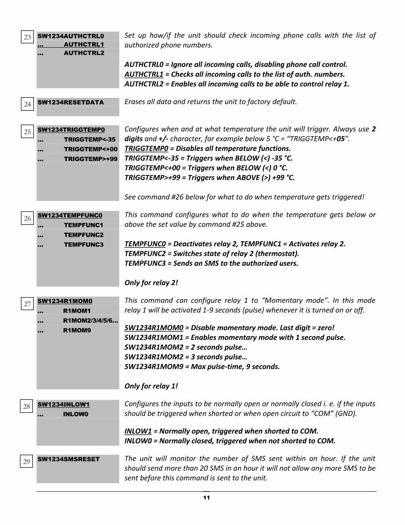
Set up how/if the unit should check incoming phone calls with the list of authorized phone numbers. AUTHCTRL0 = Ignore all incoming calls, disabling phone call control. AUTHCTRL1 = Checks all incoming calls to the list of auth. numbers. AUTHCTRL2 = Enables all incoming calls to be able to control relay 1.
Erases all data and returns the unit to factory default.
Configures when and at what temperature the unit will trigger. Always use 2 digits and +/- character, for example below 5 °C = “TRIGGTEMP<+05”. TRIGGTEMP0 = Disables all temperature functions. TRIGGTEMP<-35 = Triggers when BELOW (<) -35 °C. TRIGGTEMP<+00 = Triggers when BELOW (<) 0 °C. TRIGGTEMP>+99 = Triggers when ABOVE (>) +99 °C. See command #26 below for what to do when temperature gets triggered!
This command configures what to do when the temperature gets below or above the set value by command #25 above. TEMPFUNC0 = Deactivates relay 2, TEMPFUNC1 = Activates relay 2. TEMPFUNC2 = Switches state of relay 2 (thermostat). TEMPFUNC3 = Sends an SMS to the authorized users. Only for relay 2!
This command can configure relay 1 to “Momentary mode”. In this mode relay 1 will be activated 1-9 seconds (pulse) whenever it is turned on or off.
SW1234R1MOM0 = Disable momentary mode. Last digit = zero! SW1234R1MOM1 = Enables momentary mode with 1 second pulse. SW1234R1MOM2 = 2 seconds pulse… SW1234R1MOM2 = 3 seconds pulse… SW1234R1MOM9 = Max pulse-time, 9 seconds. Only for relay 1!
Configures the inputs to be normally open or normally closed i. e. if the inputs should be triggered when shorted or when open circuit to “COM” (GND).
INLOW1 = Normally open, triggered when shorted to COM. INLOW0 = Normally closed, triggered when not shorted to COM.
The unit will monitor the number of SMS sent within an hour. If the unit should send more than 20 SMS in an hour it will not allow any more SMS to be sent before this command is sent to the unit.
SW1234AUTHCTRL0
… AUTHCTRL1
… AUTHCTRL2
SW1234RESETDATA
SW1234TRIGGTEMP0
… TRIGGTEMP<-35
… TRIGGTEMP<+00
… TRIGGTEMP>+99
SW1234TEMPFUNC0
… TEMPFUNC1
… TEMPFUNC2
… TEMPFUNC3
SW1234R1MOM0
… R1MOM1
… R1MOM2/3/4/5/6…
… R1MOM9
SW1234INLOW1
… INLOW0
SW1234SMSRESET
23
24
25
26
27
28
29

12
This command changes the names or enables/disables an input or output in the “Overview SMS”. Max 10 characters for each name. Only letters and digits allowed. NAME=R1:HOUSE HEAT = Changes relay 1 name to “HOUSE HEAT”. NAME=R2:WATERVALVE = Changes relay 2 name to “WATERVALVE”. NAME=I1:WATERLEVEL = Changes input 1 name to “WATERLEVEL”. NAME=I2:ALARM = Changes input 2 name to “ALARM”.
NAME=R1:! / NAME=R2:! / NAME=I1:! / NAME=I2:! = Disable in overview.
Power
GSMS-SW22T comes in two version, one that can be power from Direct Current (DC) 12/24 Volts and another version that can be power from the mains with Alternating Current (AC) 110-230 Volts.
Inputs
The unit has two potential free inputs that can be set up to send an alert-SMS or send alert-SMS + make a phone call to the authorized phone numbers added to the unit’s memory or the inputs can be setup to activate, deactivate or switch state of a relay. For an input to be triggered the input (i1/i2) needs to be shorted to “COM” (GND) on the input terminal block. The inputs cannot be triggered by applying voltage, this will damage the device!
SW1234NAME=R1:XXXXX
… NAME=R2:XXXXX
… NAME=I1:XXXXX
… NAME=I2:XXXXX
… NAME=R1:!
… NAME=R2:!
… NAME=I1:!
… NAME=I2:!
30
SEE COMMANDS #13 #25 #26 #28

13
There is also a setting (see command #28) for reversing the triggering so that an input is triggered as soon as the circuit between COM and i1/i2 is open instead of the default closed.
Outputs
As illustrated above the outputs are potential free and each output (relay 1 and relay 2) has its own Normally Open and Normally Closed connections. Each output can handle loads (resistive) up to 10A which equals 2300W at 230VAC. The left illustration shows both relays turned off and on the right both relays is on.
Example circuit
The illustrated circuit above shows how to connect a light bulb to relay 1 that will light up when relay 1 is turned on. On the left is the GSMS-SW22T DC version and on the left the AC version.

14
Temperature functions
To utilize any of the temperature functions an external temperature sensor “sw22-ts” is required (sold separately).
Begin with connecting the external temperature sensor. Then use command #25 to configure a temperature value and if you want it to trigger when the temperature goes ABOVE (>) or BELOW (<) the set value. For example if you want an SMS when the temperature goes UNDER 0 °C, send the command “SW1234TRIGGTEMP<-00”. You also need to configure what the unit should do when the temperature is triggered, see command #26. Don’t forget to add the authorized users who shall receive the alert-SMS. This can be done in the app with “Add authorized users”.
If you rather want to control relay 2 with temperature, use command #26.
The temperature can at any time be monitored using the command “SW1234CHECK”.
Troubleshooting
I have forgotten my 4 digit password
If you have lost or forgot the 4 digit password used to control the GSMS-SW22T via SMS you will need to have physical access to the unit to do a hardware reset as described below.
The default password is “0000”.
Please note that this will erase all authorized phone numbers and change all settings to default!
1. Turn off the power to the unit and remove the transparent enclosure cover.
2. Next turn on the power to the unit again and roughly 5 seconds after the power is turned on, short/connect input 1 (i1) to the input COM and leave connected until “ERR” LED starts flashing.
After changing SIM-card in the unit, it stops responding
Every time you take in and out a SIM-card you need to restart the unit by first turning off the power and then turning it back on again. It is also possible to wait about 30 minutes and the unit will automatically detect the change.
SEE COMMANDS #13 #25 #26

15
The unit does not connect to the GSM network
1. Please make sure that the installed SIM-card does not have a PIN-lock.
2. Confirm that the SIM-card have support for the GSM/2G network.
3. Bad reception, try moving the GSMS-SW22T to another location known for good reception.
4. Make sure that you have the proper voltage range connected.
5. Confirm that the antenna is installed properly.
When calling the unit, I hear tones, but the relay does not change state
Make sure you have added your phone number to the unit’s memory. See command #13.
Input is triggered (circuit closed), but I get no SMS telling me
1. Make sure you have added your phone numbers into the unit’s memory; se command #13.
2. Confirm that the unit is set up to send SMS when the input is triggered; see command #17 and #18.
The signal ERR LED does not light up at all after power on
1. Make sure you have connected the proper voltage range.
2. Please make sure you have connected the positive and negative poles correctly.
How do I check how much money I have on the installed pre-paid SIM-card
Please talk to your SIM-card provider. Generally you can add money online and with most providers you can also register the SIM-card and monitor it online.
ERR LED is flashing
If the “ERR” LED is flashing it is an indication that something is wrong.
If the LED is flashing rapidly (multiple times a second) the unit cannot recognize the SIM-card. Try a different SIM-card!
Instead if the LED is flashing every second there is a PIN-code on the SIM-card. Please disable it!
Is it flashing every fourth second the unit cannot connect to the network. This could be an indication that insufficient coverage in the area. Please move the unit to another location or try another network operator.

16
Use this product only as specified in this manual. The manufacturer is not liable for damages caused by improper use or misuse. Do not use this product if a malfunction can result in danger for you and others and/or property damage.
This product has been developed and manufactured according to the current state of the art and recognized safety standards. It cannot be sure that the GSMS-SW22T GSM-relay works as intended under all circumstances, at all times and under all conditions.
Even if the unit nominally only uses 0,03W it needs to be connected to a 5W (for example 0.4A@12VDC or 0.2A@24VDC) power supply because of short current bursts.
The enclosure is rated IP67 (up to 1m submersion in water for 30 minutes) i. e. it is suitable for outdoor/industry use. If possible try to install the unit in a place most protected from direct sunlight.
Please note that if you want the unit to send the SMS to an international number use the following format “0046123456789” (0046 = Swedish land code) when adding authorized users.
17
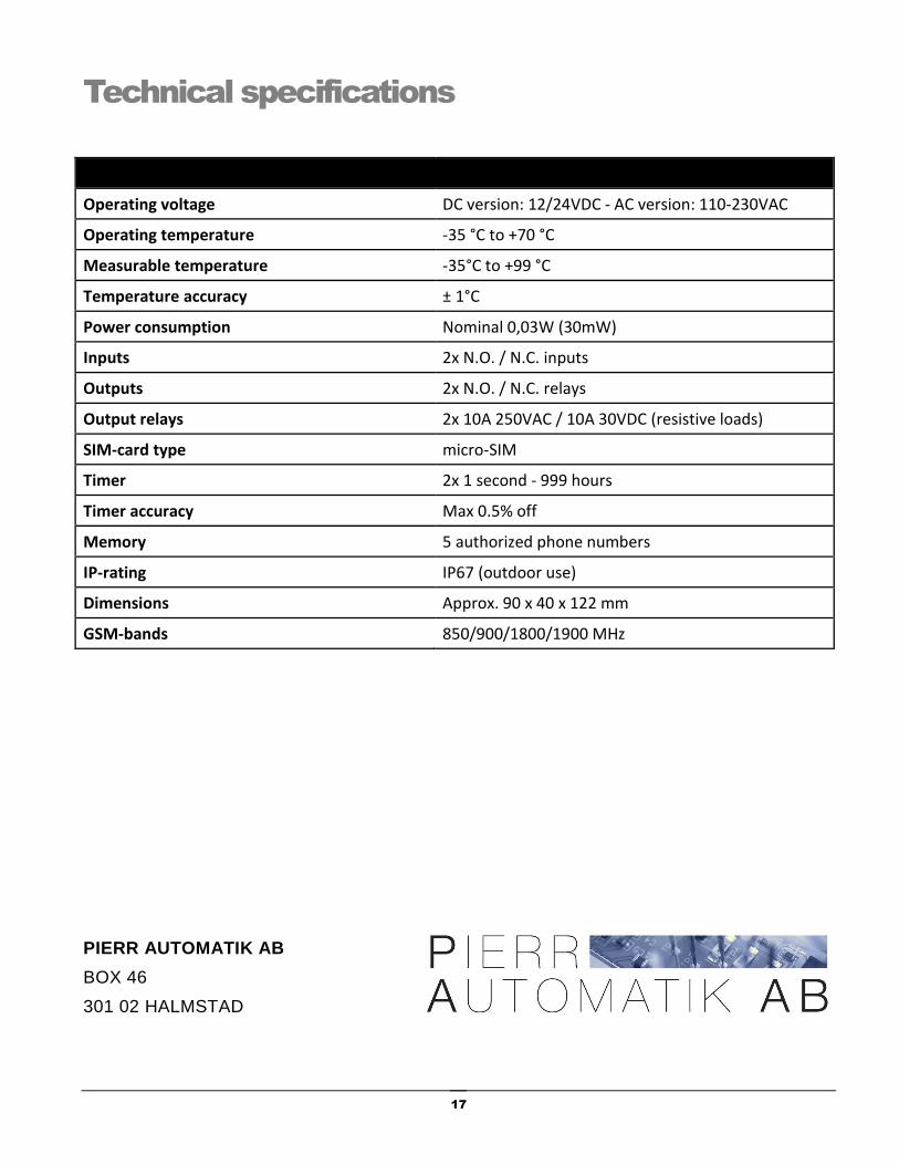
Technical specifications
Operating voltage DC version: 12/24VDC - AC version: 110-230VAC
Operating temperature -35 °C to +70 °C
Measurable temperature -35°C to +99 °C
Temperature accuracy ± 1°C
Power consumption Nominal 0,03W (30mW)
Inputs 2x N.O. / N.C. inputs
Outputs 2x N.O. / N.C. relays
Output relays 2x 10A 250VAC / 10A 30VDC (resistive loads)
SIM-card type micro-SIM
Timer 2x 1 second - 999 hours
Timer accuracy Max 0.5% off
Memory 5 authorized phone numbers
IP-rating IP67 (outdoor use)
Dimensions Approx. 90 x 40 x 122 mm
GSM-bands 850/900/1800/1900 MHz
PIERR AUTOMATIK AB
BOX 46
301 02 HALMSTAD


