For distributor use only Total or partial reproduction prohibited without authorization 1 GSX-S1000/A/F/FAL6 IMMOBILIZER INSTRUCTION MANUAL This manual explains key registration and cancelling procedures. This information is not published in the service manual for security reason. You are requested to keep this confi- dential. Immobilizer • The immobilizer, an anti-theft system, is installed as a standard equipment. • The immobilizer verifies that the key ID agrees with ECM ID by means of radio communication through the immobilizer antenna. When the ID agreement is verified, the system makes the engine ready to start. Immobilizer antenna Immobilizer antenna Immobilizer Indicator light Immobilizer Indicator light ID ECM Transponder Immobilizer antenna Immobilizer Indicator light May, 2015 Part No. 99522-01160-01E
Transcript
For distributor use onlyTotal or partial reproduction prohibitedwithout authorization
1
GSX-S1000/A/F/FAL6 IMMOBILIZERINSTRUCTION MANUAL
This manual explains key registration and cancelling procedures. This information is notpublished in the service manual for security reason. You are requested to keep this confi-dential.
Immobilizer• The immobilizer, an anti-theft system, is installed as a standard equipment.• The immobilizer verifies that the key ID agrees with ECM ID by means of radio communication through
the immobilizer antenna. When the ID agreement is verified, the system makes the engine ready to start.
Operation• When the ignition switch is turned ON with the engine stop switch in ON and the side stand in up position,
the immobilizer antenna and ECM are powered ON.The ECM transmits a signal to the transponder through the immobilizer antenna in order to make com-parison between the key ID and ECM ID.With the signal received, the transponder transmits the key ID signal to ECM so that ECM can makecomparison with its own ID, and if it matches, the engine is made ready to start.
Also, when the ignition switch is turned ON, the immobilizerindicator light flashes as many as the number of IDs registeredin ECM. Thereafter, if the IDs are in agreement, the indicatorlight turns on for two seconds to notify of completion in success-ful communication.If the immobilizer indicator light flashes fast, it notifies of com-munication error or disagreement of ID.
NOTE
• If the immobilizer indicator light flashes fast, turn theignition switch OFF then ON to make judgment again asthere is possible misjudgment due to environmental radiointerference.
• When the battery performance is lowered in winter (lowtemperature), the system may at times makes a re-judgment at the time of beginning the starter motoroperation. In this case, the immobilizer indicator lightoperation starts immediately after the starter operation.
ONOFF
R O
Transponder
Ignition switch Immobilizer antenna
ECM
Side-stand relayTo side-stand switch
To gear position switch
Engine stop switch
Flashing Lighting
2 registered
3 registered
4 registered
Normal
Normal
Normal
Abnormal
Fast flashing
Approx. 1.6 sec. Approx. 2.0 sec.
Immobilizer indicator light
3
• Purchase a blank key of Suzuki Genuine Parts.• Cut the key slot.• Arrange all the keys in possession that have been registered.• Arrange the special tools (Mode select switch: 09930-82720 and Adapter coupler: 09930-82750).• Register the new key ID into the motorcycle (ECM).
Procedure of registering new key ID• The maximum of four keys can be registered into the motorcycle. At least one original key (registered
key) is necessary.• If all keys are lost, ECM should be replaced.
NOTE
• Before starting the work, make sure to read the instructions to have thorough understanding of them.
• Carry out the work with two or more operators as verification works are necessary.
• Once the new ID motorcycle registration mode is executed, all the registered IDs except the firstinserted key will be canceled.
• Re-register all the keys that are intended for use.
• At least two keys must be registered into the motorcycle. If only one key is registered, the enginestarting is not possible.
• During registration work, avoid disconnecting the battery terminal.
• During registration work, avoid turning off the engine stop switch.
• During registration work, avoid squeezing the clutch or depressing the starter button.
Registration procedure
NOTE
• The battery must be fully charged.
• Refer to service manual for exterior parts removal andinstallation.
1) Remove the front seat.2) Lift and support the fuel tank.
3) Remove the ECM (1).
CAUTION!
Do not disconnect the ECM couplers.
4) Remove the air cleaner bolt (2).
To make a spare key
1
2
4
5) Loosen the air cleaner outlet clamp screws (3).
6) Disconnect the IAT sensor coupler (4) and PAIR hose (5).7) Remove the AP sensor (6) and IAP sensor (7).
8) Disconnect the ISC hose (8) and PCV hose (9).9) Remove the air cleaner box.
10) Install the immobilizer antenna (10).11) Turn ON the engine stop switch.12) Shift the transmission into neutral.
13) Open the fuse box and remove the headlight (HEAD-LO),(HEAD-HI) fuses (10 A) (11).
33
475
6
8
9
10
11
5
14) Disconnect the cap from the mode select coupler (6P)(12), connect the special tool (Mode select switch) into thecoupler and turn ON the mode select switch.
NOTE
Do not turn OFF the mode select switch until theregistration has been completed.
15) Insert any of the registered keys into the ignition switch.
NOTE
Keep the ignition switch in OFF position.
16) Remove the ignition switch coupler (13) and connect thespecial tool (Adapter coupler).
NOTE
• The ignition switch coupler is located at the forward ofthe cylinder head cover.
• Do not remove the adapter coupler until theregistration has been completed.
• The radio communication starts from the time ofinstalling the special tool.
• After the adapter has been inserted, the indicator lightflashes as many as the number of IDs registered inECM. Approximately 1.6 seconds after the adapter hasbeen inserted, the indicator starts to light for 2 seconds.
When the indicator light flashing is fast (0.3 sec. of frequency)If the indicator light flashing is fast, it is due to failure in reading the ID and therefore restart thework right from the beginning with the two special tools removed.
17) Within 30 seconds after the indicator light has lighted for 2 seconds then gone off, remove the insertedkey.
18) When the indicator light has come on again, insert the key that is being registered within 30 seconds.
NOTE
At the time when the indicator light has come on again, all the registries except the first inserted keyare canceled from the motorcycle (ECM).
19) If the indicator light flashes slow (1 sec. of frequency) or goes off, it means that the registration hasbeen completed successfully.
☆ In the case that the indicator light flashes slowly, there are some more memory space left allowingan addition registration within 30 seconds.
☆ In the case that the indicator light goes off, there is no more memory space for additional registra-tion. In the case that the indicator light flashes fast (0.3 sec. of frequency)
In this case, it means a failure in reading ID and therefore restart the works from the beginningwith the two special tools removed.
20) If the indicator light has gone off, the registration work has been completed. If the additional registra-tion is not needed although the flashing is slow, finish the registration work.
21) Remove the key.22) If the additional registration is not needed, remove the special tools.23) Repeating the procedures from 19) the following, if the additional registration is needed.
12
Turn ON.Turn ON.
12
Turn ON.Turn ON.
13
6
24) Install the removed parts in the reverse order of removal.Pay attention to the following points:
• Tighten the air cleaner outlet clamp screws (14) to thespecified torque.
Tightening torqueAir cleaner outlet clamp screw:
1.5 N·m (0.15 kgf-m, 1.10 lbf-ft)
• Tighten the air cleaner bolt (15) to the specified torque.
• When disconnecting the mode select switch (specialtool), do not pull it forcedly, otherwise terminal dislodg-ment or lead disconnection may result.
• Pushing in the coupler to loosen the lock pawl thendepressing the lock lever will disengage the lock pawlallowing the coupler to be easily pulled free.
1414
15
PawlPawl
Lock leverLock leverLock lever
7
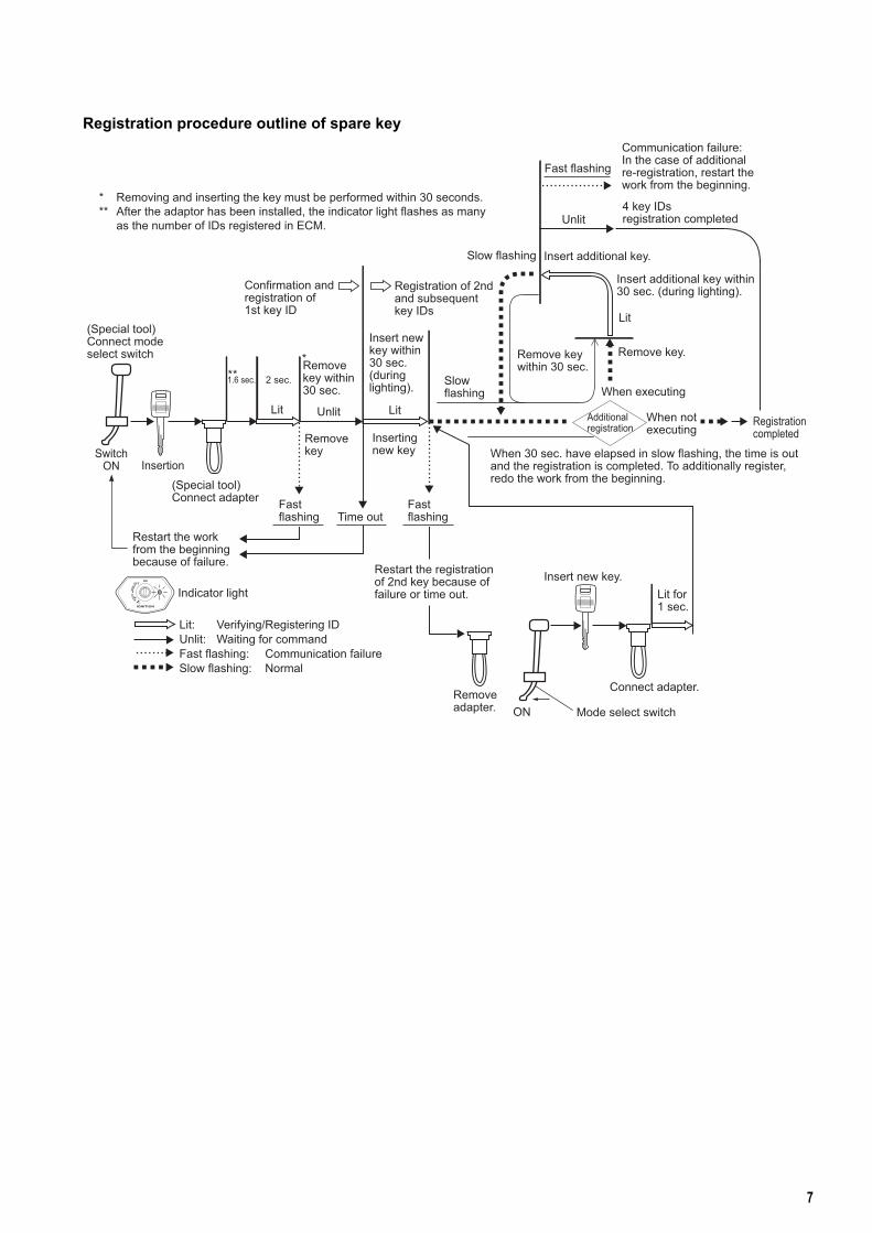
Registration procedure outline of spare key
SwitchON Insertion
ON
Confirmation andregistration of1st key ID
Registration of 2ndand subsequentkey IDs
Fast flashing
Communication failure:In the case of additionalre-registration, restart thework from the beginning.
Unlit4 key IDsregistration completed
Slow flashing Insert additional key.
Insert additional key within30 sec. (during lighting).
When 30 sec. have elapsed in slow flashing, the time is outand the registration is completed. To additionally register,redo the work from the beginning.
Restart the registrationof 2nd key because offailure or time out.
Insert new key.Indicator light
Remove adapter.
Lit for1 sec.
Connect adapter.
Mode select switch
Restart the workfrom the beginningbecause of failure.
* * *
* Removing and inserting the key must be performed within 30 seconds.** After the adaptor has been installed, the indicator light flashes as many as the number of IDs registered in ECM.
Lit: Verifying/Registering IDUnlit: Waiting for commandFast flashing: Communication failureSlow flashing: Normal
8
• Prepare one key that was used on the previous ignition switch.• Prepare two keys that come packed with the new ignition switch.• Prepare special tools (Mode select switch: P/No. 09930-82720 and Adapter: P/No. 09930-82750).
Procedure of registering new key1) Replace the ignition switch.2) Insert the old key.3) In accordance with the registration procedures when making a spare key, register two new keys.
NOTE
• When the registration has been completed, the old key ID still remains in the registry of themotorcycle.
• When deleting of old key ID from the motorcycle registry is needed, restart the work without theold key after the registration work has been completed.
• Unless at least two keys are registered, the engine will be unable to start.
• Prepare new ECM.• Prepare the key that was previously used.• The key ID needs to be registered into the motorcycle (ECM).• Unless at least two keys are registered, the engine can not be started.
NOTE
• Before starting the work, make sure to read the registration instructions to have thoroughunderstanding of them.
• Carry out the work with two or more operators as verification works are necessary.
• Re-register all they keys that are intended for use.
• At least two keys must be registered into the motorcycle. If only one key is registered, the enginestarting is not possible.
• During registration work, avoid disconnecting the battery terminal.
• During registration work, avoid turning off the engine stop switch.
• During registration work, avoid squeezing the clutch or depressing the starter button.
To replace ignition switch
To replace ECM
9
Procedure of registering new key1) Replace ECM.2) With the engine stop switch in ON position, insert the key used previously or the key to be newly regis-
tered and twist it to turn ON the ignition switch.3) The indicator light will be lit.4) When the indicator light lighting mode changes to a slow flashing, then the registration of the 1st key is
now complete.5) Turn the ignition switch OFF and remove the 1st key that has been registered.6) Register the 2nd key, repeating the procedures from 2) the following.
NOTE
To register three keys, carry out the registration following the procedures “To make a spare key”after completing the 2nd key registration.
Registration procedure outline when replacing ECM
IgnitionOFF Restart works
from the beginningbecauseof failure.
Restart works from thebeginning because ofcommunication failure.
Fast flashing
UnlitLit for1 sec. Slow flashing
IgnitionON
IgnitionOFF
Ignition OFF
IgnitionON
Ignition OFF
Remove keyto completeprocedures.
Indicator light
Slow flashing
Fast flashing
UnlitLit for1 sec.
Lit: Registering IDUnlit: Waiting for commandFast flashing: Communication failureSlow flashing: Normal
Turn OFF ignition within 30 sec.Light goes off when time is out.1st key ID registration complete.