GT 210 A Oil-Gas Fired Hot Water Boiler English 11/03/09 Warning: Before putting the boiler into operation read this manual carefully. Warning: The operating manual is part of the documentation that is delivered to the installation’s operator. Go through the information in this manual with the owner/operator and make sure that he or she is familiar with all the necessary operating instructions. Notice: This manual must be retained for future reference. Improper installation, adjustment, alteration, service or maintenance can cause injury, loss of life or property damage. Refer to this manual. For assistance or additional information consult a qualified installer, service agency or the fuel supplier. Installation & Operating Manual Please Read & Save this Manual for Future Reference 8227-4096-F 8227-4096-F
Transcript
GT 210 AOil-Gas Fired Hot Water Boiler English
11/03/09
Warning:Before putting the boiler into operation read this manualcarefully.
Warning:The operating manual is part of the documentation that isdelivered to the installation’s operator. Go through theinformation in this manual with the owner/operator andmake sure that he or she is familiar with all the necessaryoperating instructions.
Notice:This manual must be retained for future reference. Improperinstallation, adjustment, alteration, service or maintenance cancause injury, loss of life or property damage. Refer to thismanual. For assistance or additional information consult aqualified installer, service agency or the fuel supplier.
Installation & Operating Manual Please Read & Save this Manual for Future Reference
8227-4096-F 8227-4096-F
Guideline of Notices
Warning:indicates presence of hazards that can cause, if notavoided, severe personal injury, death or substantialproperty damage.
! Caution:indicates presence of hazards that will or can cause, if notavoided, minor personal injury or property damage.
Notice:Application comment for optimum use of equipment andadjustment as well as useful information.
Reference to an other instruction book.
Observe the following symbols
DANGERdue to explosion of gas.
- Work only on gas components when you have a license to do so.- Note that the assembly of gas and vent connections, the initial
start-up, the electrical connections, the maintenance and servicecan only be performed by a licensed service contractor ortechnician.
DANGERdue to electricity.
- Prior to doing any work on the heating system, disconnect allelectrical power to the boiler at the emergency switch.
- It is NOT sufficient to shut off only the boiler control!
! CAUTION!SYSTEM DAMAGEdue to improper installation.
- Observe local and state codes as well as common industrypractices during the installation and operation of the heatingappliance.
! CAUTION!SYSTEM DAMAGEdue to inadequate cleaning and maintenance.
- A boiler cleaning and maintenance should be performed annually.Verify complete system operation at the same time.
- Correct the problem immediately to prevent damage to thesystem!
! Caution:Refer to User’s Manual regarding the carcinogenic hazard ofcrystalline silica that may be found during installation, servicingand removal of this boiler.
Safety Considerations
Please observe the following safety instructions.Read this manual carefully.Correct installation and adjustment of the burner and the controlpanel is a precondition for safe, efficient operation of the boiler.Read this manual and the specifications on the safety label carefullybefore attempting to put the burner into operation.
Do not store or use gasoline or other flammable liquids inthe vicinity of this or any other appliance.
WHAT TO DO IF YOU SMELL GAS:- Do not try to light any appliance.- Do not touch any electric switch, do not use any phone inyour building.- Immediately call your gas supplier from a neighbor’sphone. Follow the gas supplier’s instructions.- If you cannot reach your gas supplier, call the FireDepartment.
Installation and service must be performed by a qualifiedinstaller, service agency or the gas supplier.
Warning:Improper installation, adjustment, and/or operation couldcause carbon monoxide poisoning resulting in injury ordeath.This product must be installed and serviced by aprofessional service technician who is experienced andqualified in hot water boiler installation and gascombustion.
! Caution: Strict compliance with these instructions is aprecondition for the correct operation of the boiler.
! IMPORTANTService on this boiler should be undertaken only by trained andskilled personnel.Keep boiler area clear and free from combustible materials,gasoline and other flammable vapors and liquids.Do not place any obstruction in the boiler room that will hinderthe flow of combustion and ventilating air.Read these instructions carefully before proceeding with theinstallation of boiler. Post instructions near boiler for referenceby owner and serviceman.Maintain instructions in legible condition.
"Installation of this equipment must be in accordance to all local and national codes or authorities having jurisdiction”[Canadian Installations]
• CSA B149 for gas fired boilers • CSA B139 for oil fired boilers
[USA Installations]
• NFPA 54/ANSI Z223.1 for gas fired boiler • NFPA 31 for oil fired boilers.
ATTENTION-WARNING: The boiler must be connected to a venting system that will safely discharge all flue gas to the outside in a safe and effective manner.
Do not use gasoline, crankcase draining, or any other oil containing gasoline.
The boiler is certified to burn fuels as listed on the boiler rating plate. Never burn garbage or paper in the unit, and never leave combustible materials in the vicinity of the boiler.
The installation must conform to the requirements of the authorityhaving jurisdiction or, in the absence of such requirements, to theNational Fuel Gas Code, ANSI Z 223.1 / NFPA 54. In Canada,installation must be in accordance with the requirements of CAN/CGA B149.1 or 2 Installation Code for Gas Burning Appliances andEquipment. Where required by the authority having jurisdiction, theinstallation must conform to the Standard for Controls and SafetyDevices for Automatically Fired Boilers, ANSI/ASME CSD-1.Install CO detectors per local regulations. Boiler requires yearlymaintenance, see "Connecting the burner", page 24.
Only a qualified installing contractor may carry out the installation, theinitial start-up, the connection for fixed gas and vent gas, andconversion to another type of gas. The hot water distribution systemmust comply with the applicable codes and regulations. Whenreplacing an existing boiler, it is important to check the entire hotwater distribution system to insure safe operation. Maintenance andcleaning must be carried out at least once a year by a trained servicetechnician. The entire installation must be tested for properoperation. Any defects detected must be fixed immediately.
General
1 Uncrating
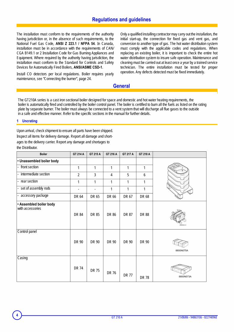
Upon arrival, check shipment to ensure all parts have been shipped. Inspect all items for delivery damage. Report all damage and short-ages to the delivery carrier. Report any damage and shortages to the Distributor.
Boiler GT 214 A GT 215 A GT 216 A GT 217 A GT 218 A
• Unassembled boiler body- front section 1 1 1 1 1- intermediate section 2 3 4 5 6- rear section 1 1 1 1 1- set of assembly rods - - 1 1 1- accessory package DR 64 DR 65 DR 66 DR 67 DR 68
• Assembled boiler bodywith accessories
DR 84 DR 85 DR 86 DR 87 DR 88
Control panel
DR 90 DR 90 DR 90 DR 90 DR 90
Casing
DR 74 DR 75 DR 76 DR 77 DR 78
8800N072
The GT210A series is a cast iron sectional boiler designed for space and domestic and hot water heating requirements, the boiler is automatically fired and controlled by the boiler control panel. The boiler is certified to burn all the fuels as listed on the rating plate by separate burner. The boiler must always be connected to a vent system that will discharge all flue gases to the outside in a safe and effective manner. Refer to the specific sections in the manual for further details.
4 GT 210 A 21/08/06 - 94863106 - 82274096E
2 Technical specifications of boilers
Item Unit GT 214 A GT 215 A GT 216 A GT 217 A GT 218 A
Bolt Ø = 5 15/16 inch M8 x 1.25 Bolt diameter threading predrilled, additional marking @ 6 ¾ inch for larger mounting requirements.
4
5
Combustion head Ø = 4 7/16 inch precut, additional marking @ 5 1/8 inch for larger combustion heads.
Supply manifold ¾” port for safety relief valve
Supply manifold ¼ inch port for temperature and pressure gauge
Drain port ¾ inch.
1
A* = Dimension will increase with applied burner, consult supplied burner documentation for dimensions and clearances for service/ combustibles.
D** = OD Dimension will for breeching connection only actual vent diameter sizing will depend on specific vent application and code requirements.
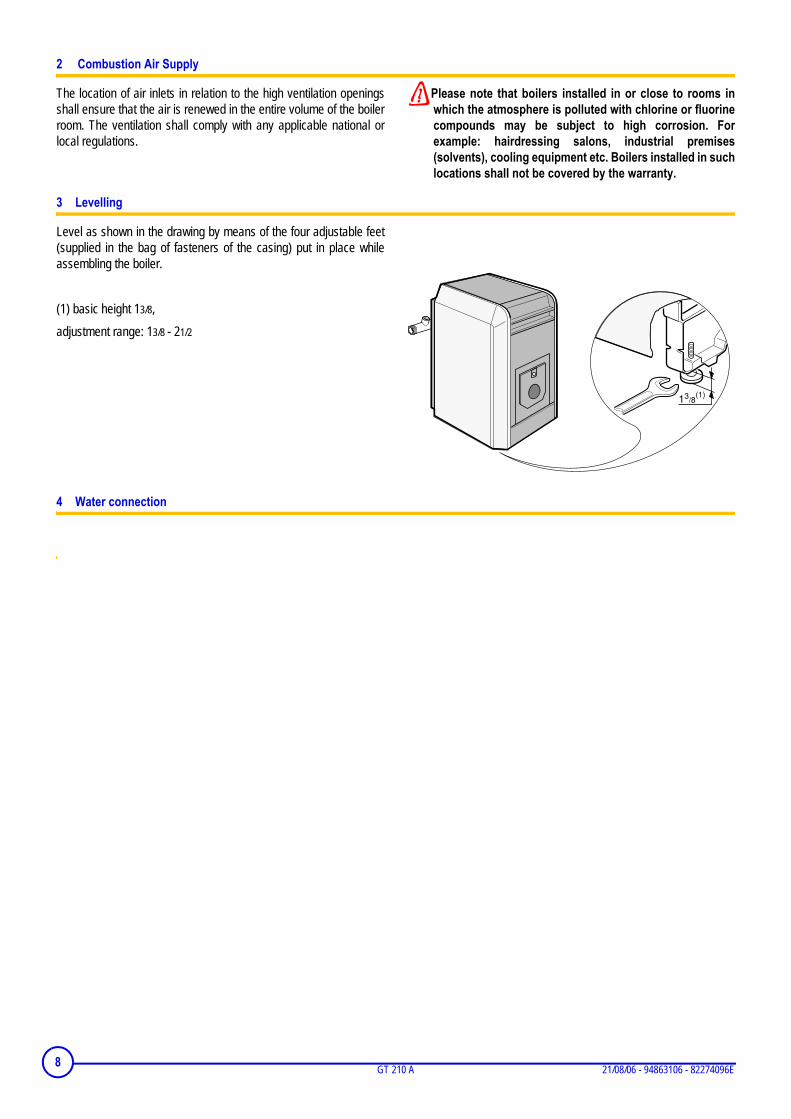
(1) = Adjustable hot water tank feet for leveling, minimum height =1 3/16 inch, adjustable from 1 3/16 to 2 1/2 inch.
6 GT 210 A 01/08/08 - 82274096F
L
X
8227
N05
8A
3/4"-1"
To facilitate boiler transportation into the final installation site, a special handling tool (package BG 45, no.8218-7723) may be used as shown to transport the boiler or the boiler on the MLS horizontal domestic hot water tank. The two 3/4” or 1” pipes are shown are not supplied with the package BG45, they are supplied by others.
Installation
1 Installing the boiler
The boiler does not require any special housekeeping pad as it has been provided with a study frame and leveling bolts for the final installation, but a non combustible pad is suggested to keep occasional water away from the boiler. The boiler requires clearance for combustibles and for servicing, the recommended clearance as shown in the table below. Do not install the boiler on combustible flooring or carpet.
Proper combustion air and ventilation are required for the boiler, inadequate combustion air or makeup air provisions may result in foul boiler room odors, incomplete combustion resulting in carbon monoxide (CO) development or creation of negative building pressure.
Particular attention must be observed if the boiler is operating near or within vicinity of beauty shops, paint shops or industrial plant where known pollutants, corrosive element may containment affect the quality of combustion air supply, failure to observe this warnings will result in void of warranty of the boiler and any responsibility of De Dietrich.
Consult local codes for combustion air and ventilation requirements, each installation must comply with all local and national codes having jurisdiction.
Model L = overall length Sides Rear X = Front
burner Top Vent
GT214A 29 11/16
[754mm]
GT215A 34 11/16
[881mm]
GT216A 39 11/16
[1008mm]
GT217A 32 11/16
[1135mm]
GT218 33 11/16
[1262mm]
20 inches [500mm]
20 inches [500mm]
34 inches [800mm]
24 inches [600mm] in
front of burner
Combustible & Service Clearances
GAS = 6 inches [150mm]
OIL = 9 inches [230mm]
701/08/08 - 82274096F GT 210 A
2 Combustion Air Supply
The location of air inlets in relation to the high ventilation openingsshall ensure that the air is renewed in the entire volume of the boilerroom. The ventilation shall comply with any applicable national orlocal regulations.
Please note that boilers installed in or close to rooms inwhich the atmosphere is polluted with chlorine or fluorinecompounds may be subject to high corrosion. Forexample: hairdressing salons, industrial premises(solvents), cooling equipment etc. Boilers installed in suchlocations shall not be covered by the warranty.
3 Levelling
Level as shown in the drawing by means of the four adjustable feet(supplied in the bag of fasteners of the casing) put in place whileassembling the boiler.
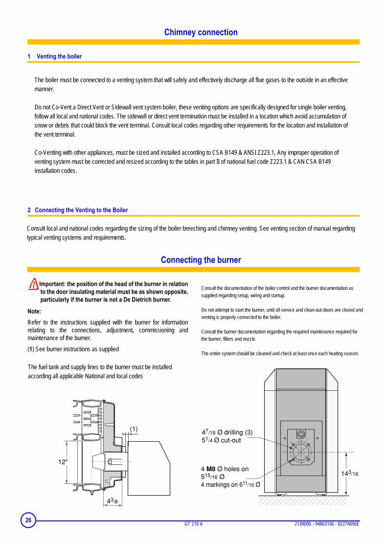
Important: the position of the head of the burner in relationto the door insulating material must be as shown opposite,particularly if the burner is not a De Dietrich burner.
Note:Refer to the instructions supplied with the burner for informationrelating to the connections, adjustment, commissioning andmaintenance of the burner.(1) See burner instructions as supplied
12"
43/8
(1)
143/164 M8 Ø holes on 515/16 Ø 4 markings on 611/16 Ø
47/16 Ø drilling (3) 51/4 Ø cut-out
The boiler must be connected to a venting system that will safely and effectively discharge all flue gases to the outside in an effective manner. Do not Co-Vent a Direct Vent or Sidewall vent system boiler, these venting options are specifically designed for single boiler venting, follow all local and national codes. The sidewall or direct vent termination must be installed in a location which avoid accumulation of snow or debris that could block the vent terminal. Consult local codes regarding other requirements for the location and installation of the vent terminal. Co-Venting with other appliances, must be sized and installed according to CSA B149 & ANSI Z223.1, Any improper operation of venting system must be corrected and resized according to the tables in part II of national fuel code Z223.1 & CAN CSA B149 installation codes.
Consult local and national codes regarding the sizing of the boiler breeching and chimney venting. See venting section of manual regarding typical venting systems and requirements.
Consult the documentation of the boiler control and the burner documentation as supplied regarding setup, wiring and startup. Do not attempt to start the burner, until all service and clean-out doors are closed and venting is properly connected to the boiler. Consult the burner documentation regarding the required maintenance required for the burner, filters and nozzle. The entire system should be cleaned and check at least once each heating season.
The fuel tank and supply lines to the burner must be installed according all applicable National and local codes
26 GT 210 A 21/08/06 - 94863106 - 82274096E
3. Boiler Venting & Chimney General
Caution & Warning:
It is advised and recommended that the heating contractor-professional apply vent materials that are approved and agency listed. Installation of any venting must follow all local codes in conjunction with vent manufacturer instructions and appliance manufacturer instructions. All De Dietrich GT series oil-gas fired cast iron boilers are high performance boilers that could operate under all 4 vent categories as established by ANSI Z21.13/CSA 4.9 Standard. To assist with application where the vent category is unknown a graph below has been provided to assist you in determining the vent category and what venting materials would be acceptable. Although the gas vent categories were developed specifically for gas fired appliances, using this information is helpful for oil fired boilers. It is very important the venting be selected according to the conditions that the boiler will operate under, minimum and maximum firing conditions of the boiler must be respected. The venting installed must comply and be certified to all applicable codes and standards for each jurisdiction. Gas-Vent Category [4] Definitions: Cat. I A Boiler, which operates with a non-positive vent (breech) pressure and flue gas temperatures which avoids excessive condensation production in the chamber and venting. Cat. II A Boiler, which operates with a non-positive vent (breech) pressure and flue gas temperatures produce condensation production in the chamber and venting.
Cat. III A Boiler, which operates with a positive vent (breech) pressure and flue gas temperatures which avoids excessive condensation production in the chamber and venting. Cat. IV A Boiler, which operates with a positive vent (breech) pressure and flue gas temperatures produces condensation production in the chamber and venting.
Chart A
Gas-Fired Appliance Vent Categorization [According to ANSI Z21.13/CSA 4.9 Gas Boiler Standard]
60
104
148
192
236
280
324
368
412
456
500
Chimney-Vent Pressure [Inches w.c.]
Chi
mne
y-V
ent F
lue
Gas
Tem
pera
ture
°F
(Net
, Min
us R
oom
Tem
pera
ture
)
15
40
64
89
113
138
162
187
211
236
2606 7 8 9 10 11 12 11 10 9 8 7 6
Carbon Dioxide [CO2] Content %
Chi
mne
y-V
ent F
lue
Gas
Tem
pera
ture
°C
(Net
, Min
us R
oom
Tem
pera
ture
)Category I
Typical Vent Types [A,B,C & L]Category III
Typical Vent Types [BH, AL294C®, 304-316L SS]
PositiveNegative
Category IITypical Vent Types
[BH, AL294C®, 304-316L SS]
Category IVTypical Vent Types
[BH, AL294C®, 304-316L SS]
Chart created by Craig Holdforth
Venting
27
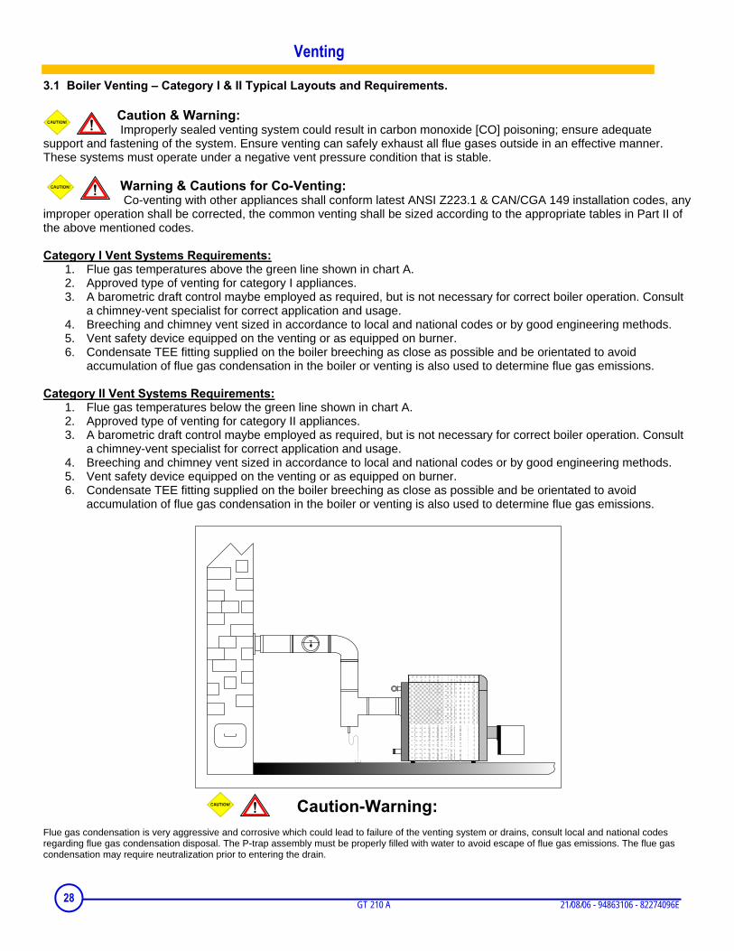
3.1 Boiler Venting – Category I & II Typical Layouts and Requirements.
Caution & Warning: Improperly sealed venting system could result in carbon monoxide [CO] poisoning; ensure adequate
support and fastening of the system. Ensure venting can safely exhaust all flue gases outside in an effective manner. These systems must operate under a negative vent pressure condition that is stable.
Warning & Cautions for Co-Venting: Co-venting with other appliances shall conform latest ANSI Z223.1 & CAN/CGA 149 installation codes, any
improper operation shall be corrected, the common venting shall be sized according to the appropriate tables in Part II of the above mentioned codes. Category I Vent Systems Requirements:
1. Flue gas temperatures above the green line shown in chart A. 2. Approved type of venting for category I appliances. 3. A barometric draft control maybe employed as required, but is not necessary for correct boiler operation. Consult
a chimney-vent specialist for correct application and usage. 4. Breeching and chimney vent sized in accordance to local and national codes or by good engineering methods. 5. Vent safety device equipped on the venting or as equipped on burner. 6. Condensate TEE fitting supplied on the boiler breeching as close as possible and be orientated to avoid
accumulation of flue gas condensation in the boiler or venting is also used to determine flue gas emissions.
Category II Vent Systems Requirements: 1. Flue gas temperatures below the green line shown in chart A. 2. Approved type of venting for category II appliances. 3. A barometric draft control maybe employed as required, but is not necessary for correct boiler operation. Consult
a chimney-vent specialist for correct application and usage. 4. Breeching and chimney vent sized in accordance to local and national codes or by good engineering methods. 5. Vent safety device equipped on the venting or as equipped on burner. 6. Condensate TEE fitting supplied on the boiler breeching as close as possible and be orientated to avoid
accumulation of flue gas condensation in the boiler or venting is also used to determine flue gas emissions.
Caution-Warning: Flue gas condensation is very aggressive and corrosive which could lead to failure of the venting system or drains, consult local and national codes regarding flue gas condensation disposal. The P-trap assembly must be properly filled with water to avoid escape of flue gas emissions. The flue gas condensation may require neutralization prior to entering the drain.
Venting
28 GT 210 A 21/08/06 - 94863106 - 82274096E
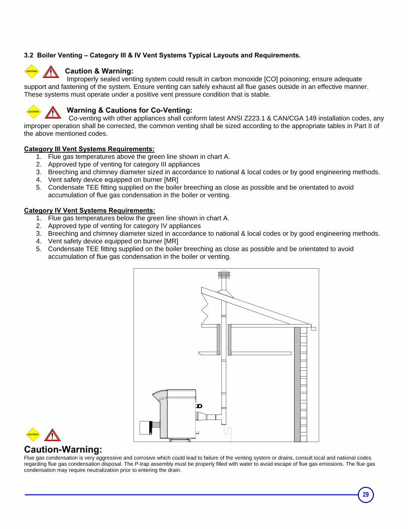
3.2 Boiler Venting – Category III & IV Vent Systems Typical Layouts and Requirements.
Caution & Warning: Improperly sealed venting system could result in carbon monoxide [CO] poisoning; ensure adequate
support and fastening of the system. Ensure venting can safely exhaust all flue gases outside in an effective manner. These systems must operate under a positive vent pressure condition that is stable.
Warning & Cautions for Co-Venting: Co-venting with other appliances shall conform latest ANSI Z223.1 & CAN/CGA 149 installation codes, any
improper operation shall be corrected, the common venting shall be sized according to the appropriate tables in Part II of the above mentioned codes. Category III Vent Systems Requirements:
1. Flue gas temperatures above the green line shown in chart A. 2. Approved type of venting for category III appliances 3. Breeching and chimney diameter sized in accordance to national & local codes or by good engineering methods. 4. Vent safety device equipped on burner [MR] 5. Condensate TEE fitting supplied on the boiler breeching as close as possible and be orientated to avoid
accumulation of flue gas condensation in the boiler or venting.
Category IV Vent Systems Requirements: 1. Flue gas temperatures below the green line shown in chart A. 2. Approved type of venting for category IV appliances 3. Breeching and chimney diameter sized in accordance to national & local codes or by good engineering methods. 4. Vent safety device equipped on burner [MR] 5. Condensate TEE fitting supplied on the boiler breeching as close as possible and be orientated to avoid
accumulation of flue gas condensation in the boiler or venting.
Caution-Warning: Flue gas condensation is very aggressive and corrosive which could lead to failure of the venting system or drains, consult local and national codes regarding flue gas condensation disposal. The P-trap assembly must be properly filled with water to avoid escape of flue gas emissions. The flue gas condensation may require neutralization prior to entering the drain.
29
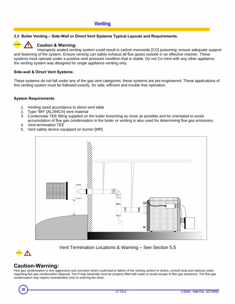
3.3 Boiler Venting – Side-Wall or Direct Vent Systems Typical Layouts and Requirements.
Caution & Warning: Improperly sealed venting system could result in carbon monoxide [CO] poisoning; ensure adequate support
and fastening of the system. Ensure venting can safely exhaust all flue gases outside in an effective manner. These systems must operate under a positive vent pressure condition that is stable. Do not Co-Vent with any other appliance, the venting system was designed for single appliance venting only. Side-wall & Direct Vent Systems: These systems do not fall under any of the gas vent categories, these systems are pre-engineered. These applications of this venting system must be followed exactly, for safe, efficient and trouble free operation. System Requirements:
1. Venting sized accordance to direct vent table 2. Type “BH” [AL294C®] vent material 3. Condensate TEE fitting supplied on the boiler breeching as close as possible and be orientated to avoid
accumulation of flue gas condensation in the boiler or venting is also used for determining flue gas emissions. 4. Vent termination TEE 5. Vent safety device equipped on burner [MR]
Vent Termination Locations & Warning – See Section 5.5
Caution-Warning: Flue gas condensation is very aggressive and corrosive which could lead to failure of the venting system or drains, consult local and national codes regarding flue gas condensation disposal. The P-trap assembly must be properly filled with water to avoid escape of flue gas emissions. The flue gas condensation may require neutralization prior to entering the drain.
30 GT 210 A 21/08/06 - 94863106 - 82274096E
Venting
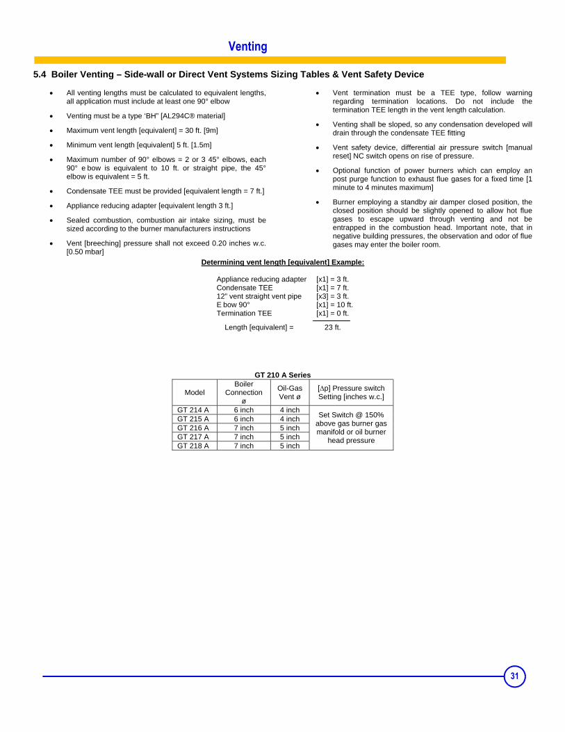
5.4 Boiler Venting – Side-wall or Direct Vent Systems Sizing Tables & Vent Safety Device
• All venting lengths must be calculated to equivalent lengths, all application must include at least one 90° elbow
• Venting must be a type ‘BH” [AL294C® material]
• Maximum vent length [equivalent] = 30 ft. [9m]
• Minimum vent length [equivalent] 5 ft. [1.5m]
• Maximum number of 90° elbows = 2 or 3 45° elbows, each 90° e bow is equivalent to 10 ft. or straight pipe, the 45° elbow is equivalent = 5 ft.
• Condensate TEE must be provided [equivalent length = 7 ft.]
• Vent termination must be a TEE type, follow warning regarding termination locations. Do not include the termination TEE length in the vent length calculation.
• Venting shall be sloped, so any condensation developed will drain through the condensate TEE fitting
• Vent safety device, differential air pressure switch [manual reset] NC switch opens on rise of pressure.
• Optional function of power burners which can employ an post purge function to exhaust flue gases for a fixed time [1 minute to 4 minutes maximum]
• Burner employing a standby air damper closed position, the closed position should be slightly opened to allow hot flue gases to escape upward through venting and not be entrapped in the combustion head. Important note, that in negative building pressures, the observation and odor of flue gases may enter the boiler room.
Determining vent length [equivalent] Example:
Appliance reducing adapter [x1] = 3 ft. Condensate TEE [x1] = 7 ft. 12” vent straight vent pipe [x3] = 3 ft.
E bow 90° [x1] = 10 ft. Termination TEE [x1] = 0 ft.
Length [equivalent] = 23 ft.
GT 210 A Series
Model Boiler
Connection ø
Oil-Gas Vent ø
[∆p] Pressure switch Setting [inches w.c.]
GT 214 A 6 inch 4 inch GT 215 A 6 inch 4 inch GT 216 A 7 inch 5 inch GT 217 A 7 inch 5 inch GT 218 A 7 inch 5 inch
Set Switch @ 150% above gas burner gas manifold or oil burner
head pressure
Venting
31
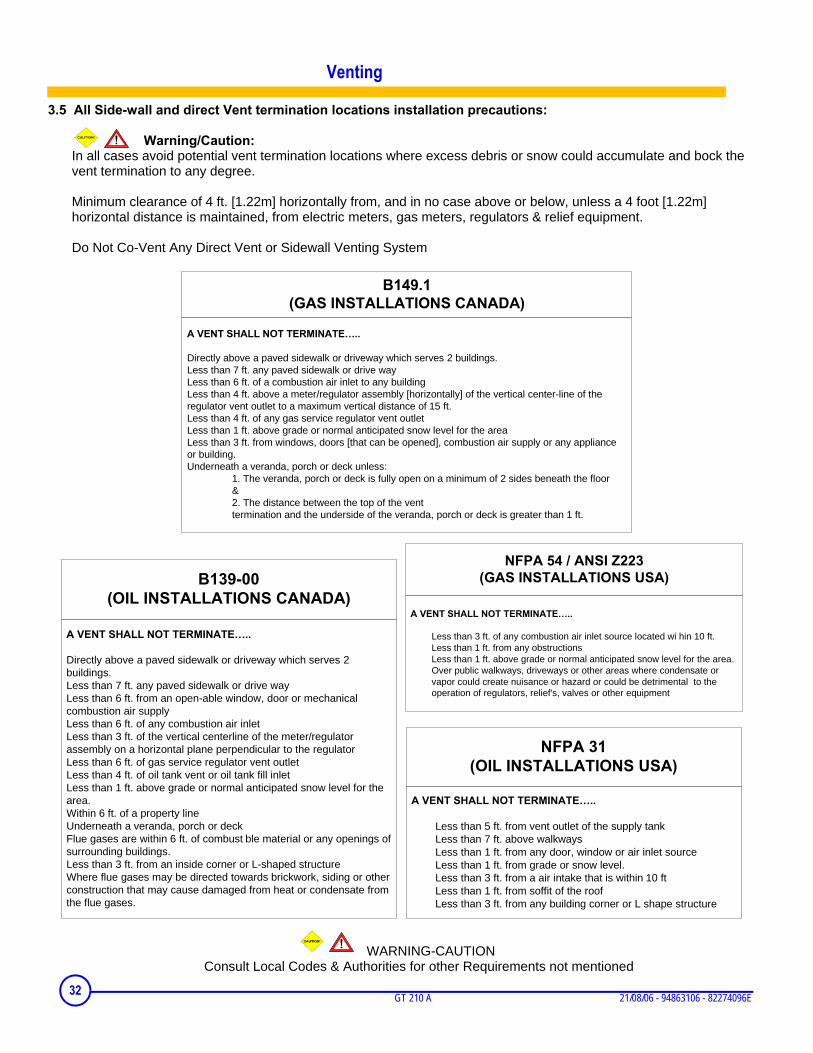
A VENT SHALL NOT TERMINATE…..
Directly above a paved sidewalk or driveway which serves 2 buildings.Less than 7 ft. any paved sidewalk or drive wayLess than 6 ft. of a combustion air inlet to any buildingLess than 4 ft. above a meter/regulator assembly [horizontally] of the vertical center-line of the regulator vent outlet to a maximum vertical distance of 15 ft.Less than 4 ft. of any gas service regulator vent outletLess than 1 ft. above grade or normal anticipated snow level for the areaLess than 3 ft. from windows, doors [that can be opened], combustion air supply or any appliance or building.Underneath a veranda, porch or deck unless:
1. The veranda, porch or deck is fully open on a minimum of 2 sides beneath the floor &2. The distance between the top of the vent termination and the underside of the veranda, porch or deck is greater than 1 ft.
B149.1(GAS INSTALLATIONS CANADA)
3.5 All Side-wall and direct Vent termination locations installation precautions:
Warning/Caution:
In all cases avoid potential vent termination locations where excess debris or snow could accumulate and bock the vent termination to any degree. Minimum clearance of 4 ft. [1.22m] horizontally from, and in no case above or below, unless a 4 foot [1.22m] horizontal distance is maintained, from electric meters, gas meters, regulators & relief equipment. Do Not Co-Vent Any Direct Vent or Sidewall Venting System
WARNING-CAUTION Consult Local Codes & Authorities for other Requirements not mentioned
A VENT SHALL NOT TERMINATE…..
Directly above a paved sidewalk or driveway which serves 2 buildings.Less than 7 ft. any paved sidewalk or drive wayLess than 6 ft. from an open-able window, door or mechanical combustion air supplyLess than 6 ft. of any combustion air inlet Less than 3 ft. of the vertical centerline of the meter/regulator assembly on a horizontal plane perpendicular to the regulatorLess than 6 ft. of gas service regulator vent outletLess than 4 ft. of oil tank vent or oil tank fill inlet Less than 1 ft. above grade or normal anticipated snow level for the area.Within 6 ft. of a property lineUnderneath a veranda, porch or deckFlue gases are within 6 ft. of combust ble material or any openings of surrounding buildings.Less than 3 ft. from an inside corner or L-shaped structureWhere flue gases may be directed towards brickwork, siding or other construction that may cause damaged from heat or condensate from the flue gases.
B139-00(OIL INSTALLATIONS CANADA)
A VENT SHALL NOT TERMINATE…..
Less than 3 ft. of any combustion air inlet source located wi hin 10 ft.Less than 1 ft. from any obstructionsLess than 1 ft. above grade or normal anticipated snow level for the area.Over public walkways, driveways or other areas where condensate or vapor could create nuisance or hazard or could be detrimental to the operation of regulators, relief's, valves or other equipment
NFPA 54 / ANSI Z223(GAS INSTALLATIONS USA)
A VENT SHALL NOT TERMINATE…..
Less than 5 ft. from vent outlet of the supply tankLess than 7 ft. above walkwaysLess than 1 ft. from any door, window or air inlet source Less than 1 ft. from grade or snow level.Less than 3 ft. from a air intake that is within 10 ftLess than 1 ft. from soffit of the roof Less than 3 ft. from any building corner or L shape structure
NFPA 31(OIL INSTALLATIONS USA)
Venting
32 GT 210 A 21/08/06 - 94863106 - 82274096E
Electrical connections
See the specific instructions supplied with the control panel of theboiler.
Maintenance
1 Boiler
DrainingWe advise you against draining the installation, unless it is absolutelynecessary. Check the water level in the installation regularly and topup if required, making sure you do not suddenly add cold water intoa hot boiler.CleaningPlease note that an efficient boiler is a boiler with cleanexchange surfaces.
The boiler should be cleaned as and when required, at least once ayear, depending upon applicable regulations and specific needs.The operation should not be required more than a few times eachseason and should not involve large quantities of water. Otherwise,look for the leak and repair it immediately.
The operations described below shall only be performedwith the boiler and power supply off.
To have access to the exchange surfaces: • take off the front of the casing,• open the door by unscrewing the two flanged nuts (17 mm wrench).
• remove the convection accelerators in the flues of the boiler with thesupplied removal hook• carefully sweep the flues with the brush supplied for that purpose• brush out the furnace as well• vacuum the soot from beneath the flues and in the furnace with asweeping brush or a vacuum cleaner with a tube diameter less than11/2• put back the convection accelerators• close the door and put back the front panel.Refer to the instructions supplied with the burner for burnermaintenance.
12
3
WarningLabel all wires prior to disconnecting when servicing controls. Wiring errors can cause improper and dangerous operation. Verify proper operation after servicing.
3321/08/06 - 94863106 - 82274096E GT 210 A
2 Domestic hot water (GT 2100)
See the instructions supplied with the MLS 150 or 250 tank.
3 Precautions required in the case of long boiler stops (one or more years)
The boiler and the chimney must be swept carefully. Close the doorof the boiler to prevent air from circulating inside the boiler.We also recommend removing the pipe connecting the boiler to thechimney and plugging the flue gas nozzle.
4 Precautions required if the heating is stopped when there is a risk of freezing
We recommend the use of a correctly dosed antifreeze agent toprevent to the heating circuit from freezing.If this cannot be done, drain the system completely.Drain the hot water tank and piping as well.
5 Boiler Rating & Approval Label
The identification plate fixed on the side of the boiler duringinstallation is used to identify the boiler correctly. It also provides themain specifications of the boiler. The serial number breakdown
The fuel main shutoff valve should be turned off if the burner is shutdown for an extended period of time.
Example X XXXX XXXX XX XX XXXXXX First digit = Approved packed boiler = A or Unapproved packaged boiler = U 4 digits = boiler series 4 digits = boiler model and control 2 digits = fuel type 03 = All 2 digits = year of manufacture last 6 digits = production
34 GT 210 A 21/08/06 - 94863106 - 82274096E
Spare parts - GT 210 A
PR82274096EWhen ordering spare parts, do not forget to state the code number given opposite the description of the required part in the liste.
BOILER BODY
10
9
11
2423
25
31
6
1
42
43
17
7
5
19
17
18
26
27 27
20
21
22
29
3011
14
13
15
16
1211
4x 1x 4x
2x2x2x
2x
2x
7
26
2727
2832
8
8
8227N154
3521/08/06 - 94863106 - 82274096E GT 210 A
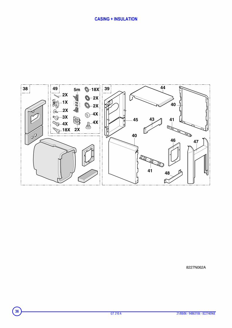
CASING + INSULATION
44
43
40
41
4746
48
40
41
45
394938
8227N062A
2X
18X
3X
4X
4X
2X
2X
18X
2X
4X
2X
1X
5m
36 GT 210 A 21/08/06 - 94863106 - 82274096E
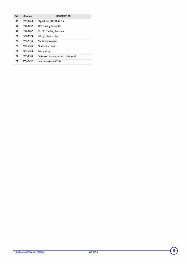
Ref. Code no. DESCRIPTION
BOILER BODY
1 8227-0033 Rear section, GT 210
2 8227-0031 Intermediate section, GT 210
3 8227-0032 Front section, GT 210
4 9508-6036 8 ø silicone seal
5 9754-9101 Flow pipe 4, 5 sections
5 9754-9151 Flow pipe 6 to 8 sections
6 8227-5506 M 8-440 assembly rod, 4 sections
6 8227-5507 M 8-580 assembly rod, 5 sections
6 8227-5508 M 8-700 assembly rod, 6 sections
6 8227-5509 M 8-820 assembly rod, 7 sections
6 8227-5510 M 8-1000 assembly rod, 8 sections
7 8336-0507 Painted nipple
8 9754-9150 1"1/4 outlet/return tube, 4 or 5 sections
In the interest of customers, DE DIETRICH & DDR Americas are continuously endeavouring to make improvements in product quality. All the specifications stated in this document are therefore subject to change without notice


![MPIA 15 459 1133 - · Dst: Type: icmp time exceeded in-transit [tos OxcO] /-----, -----\ > > > > > > > > > ® . MPIA 15 459 11302/17/99 , !](https://static.documents.pub/doc/80x56/5ab91efd7f8b9ac10d8dd314/mpia-15-459-1133-type-icmp-time-exceeded-in-transit-tos-oxco-.jpg)


