26
` GT-R Alpha 9+ Turbo Kit

`
GT-R Alpha 9+
Turbo Kit

The goal of AMS is to provide the highest quality, best performing
products available. By utilizing research and development, and
rigorous testing programs AMS will never compromise the quality
or performance of our products. In addition, AMS will only
provide the finest customer service offering only parts and advice
that are in the best interests of the customer. AMS was built on a
foundation of integrity. This is who we are; this is what you can
count on.
A vehicle modified by the use of performance parts may not meet
the legal requirements for use on public roads. Federal and state
laws prohibit the removal, modification, or rendering inoperative
of any part or element of design affecting emissions or safety on
motor vehicles used for transporting persons or property on public
streets or highways. Use or installation of performance parts may
adversely affect the drivability and reliability of your vehicle, and
may also affect or eliminate your insurance coverage, factory
warranty, and/or new OEM part warranty. Performance parts are
sold as-is without any warranty of any type. There is no warranty
stated or implied due to the stresses placed on your vehicle by
performance parts and our inability to monitor their use, tuning, or
modification.
These instructions are provided as a guide only as there are many
variables that cannot be accounted for concerning your particular
vehicle, including but not limited to model year differences, model
differences, the presence of non-OEM parts, and modifications that
may already be or were previously installed. A basic knowledge of
automotive parts and systems is helpful but a better understanding
of the parts and systems on your particular vehicle may be
required.
If you have any questions or issues at any time during the
installation of your AMS product(s) please call us for technical
assistance. The AMS tech line can be reached during business
hours at 847-709-0530 for AMS products only.

A note about this installation..
The installation of this kit is very complex. It has been engineered
for perfect fitment but if installed by someone not familiar with
aftermarket turbo systems or import vehicles mistakes can be
easily made. And in most cases mistakes will require the engine to
be dropped from the vehicle to be fixed.
This kit should only be installed by a professional technician with
correct tools and experience with aftermarket turbo systems and
the Nissan GTR.
This kit installs with tools that most technicians have, one tool that
we would highly recommend to aid in the clocking of the
compressor covers is Matco snap ring pliers part number
MST56029, from our experience these are the best pliers for the
job.

BEFORE YOU BEGIN INSTALLATION: You must verify that your turbo kit is complete by referencing the parts list above. To request, a missing part, please contact us at [email protected] with a scanned copy of the original invoice (receipt). To ensure your request is honored, the system must be purchased new and your request must be made within 90 days of the original purchase date.
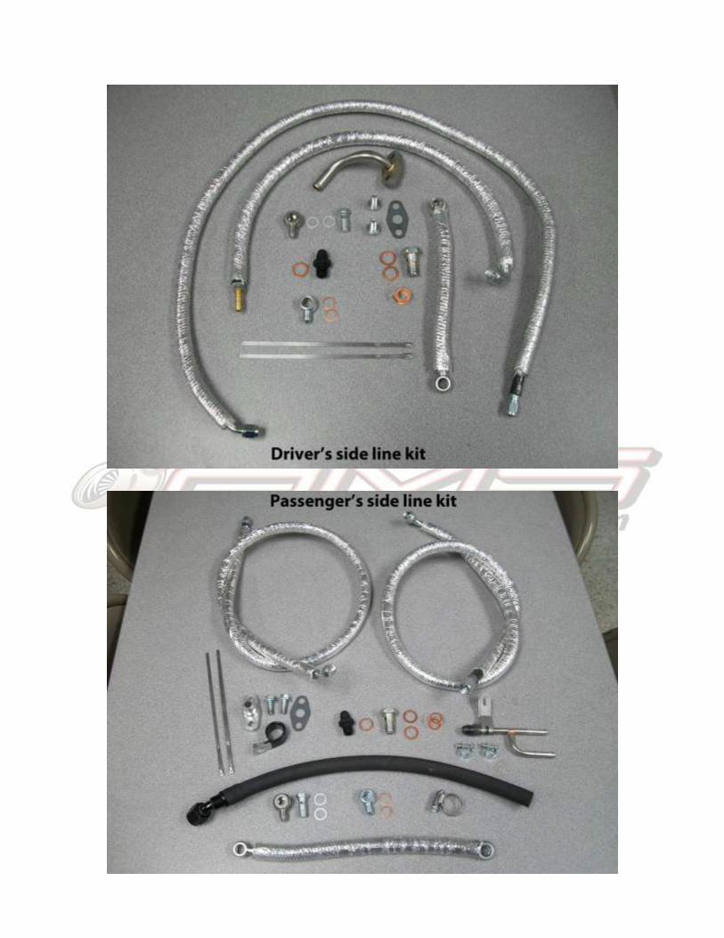
AMS ALPHA 9 GT-R TURBO UPGRADE PARTS LIST
1 Passenger Side Turbocharger 14 Driver Side Oil Feed (47”) 28 #40 Hose Clamp
2 Driver Side Turbocharger 15 Passenger Side Coolant Feed (46.25”) 29 M6x16mm Button Head Bolt (x2)
3 Passenger Side Wastegate Actuator 16 Passenger Oil Return (17.5”) 30 C-Clip - for wastegate actuator (x2)
4 Driver Side Wastegate Actuator 17 Passenger Side Coolant Return Splitter 31 M14 Copper Crush Washer (x6)
5 Passenger Hot Side Intercooler Pipe 18 Driver Side Oil Return 32 -4 Crush Washer (x4)
6 Passenger Side Silicone Compressor Coupler 19 Smooth Hose Clamp (x2) 33 M12 Copper Crush Washer (X4)
7 Driver Side Silicone Compressor Coupler 20 #6 Hose Clamp 34 M14x1.5 Straight to -6 AN Fitting (x2)
8 Passenger Hot Side Intercooler Pipe 21 7/16” -24 Hex Head Banjo Bolt (x2) 35 7/8” Tubing Clamp
9 OEM GT-R Exhaust Manifold Gasket (x2) 22 M12 Banjo Fitting (x2) May be fastened to 13 & 14 36 Oil Return Line Gasket (x2)
10 Passenger Side Coolant Feed (11.625”) 23 7/16” Banjo Fitting/-4 AN Restrictor (x2) 37 M12 Double Copper Crush Washer (x2)
11 Driver Side Coolant Feed (8.75”) 24 M14 Banjo Bolt (x2) 38 M8x20mm Bolt (x4)
12 Driver Sided Coolant Return (26”) 25 -8 GT Turbo Oil Return Flange 39 Alpha GT-R Trunk Badge
13 Passenger Side Oil Feed (49.75”) 26 LOCTITE Packet 40 8” Metal Cable Tie (x4)
27 #32 Hose Clamp (x3)

1. Drop the motor and subframe onto a safe solid table.
2. Remove stock turbochargers, downpipes, and intakes.
3. Now we will begin the installation of the Alpha 9+ kit
beginning with the driver’s side. The 1st thing to do is clock
the compressor cover. The center section has already been
pre-clocked and tightened here at AMS. This must be done
with the turbo bolted to the motor, put on the gasket and
temporarily install with a couple nuts, at least 2 on top and 2
on the bottom of the flange. Now put on the wastegate
actuator and the outlet silicone and metal tube. Bolt the metal
tube in place. Now adjust the compressor cover until the
wastegate actuator is centered and wont bind and the outlet
silicone is as tight to the motor mount as possible without
touching.

4. At this point you can now remove the turbo and install the
fittings and rear coolant line as shown.

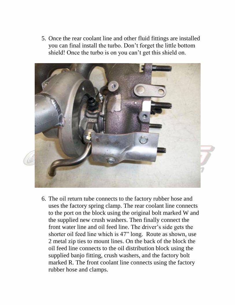
5. Once the rear coolant line and other fluid fittings are installed
you can final install the turbo. Don’t forget the little bottom
shield! Once the turbo is on you can’t get this shield on.
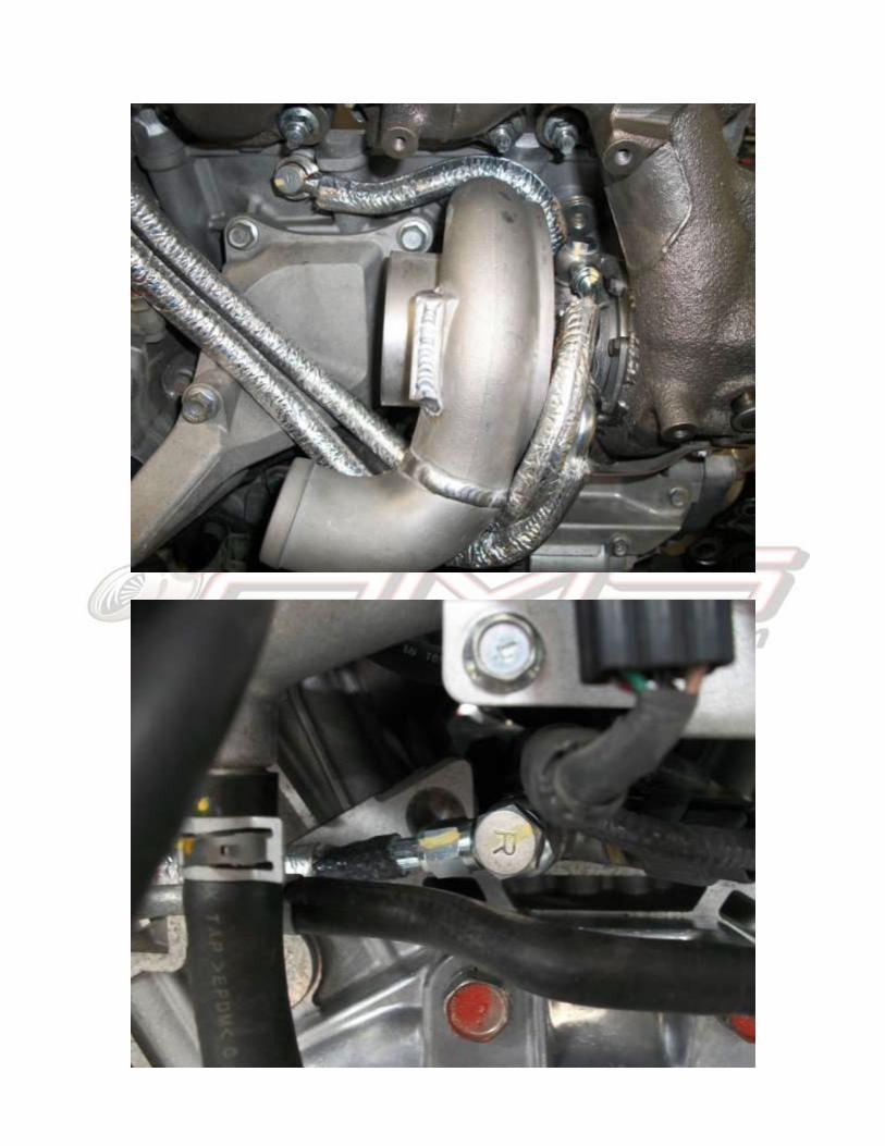
6. The oil return tube connects to the factory rubber hose and
uses the factory spring clamp. The rear coolant line connects
to the port on the block using the original bolt marked W and
the supplied new crush washers. Then finally connect the
front water line and oil feed line. The driver’s side gets the
shorter oil feed line which is 47” long. Route as shown, use
2 metal zip ties to mount lines. On the back of the block the
oil feed line connects to the oil distribution block using the
supplied banjo fitting, crush washers, and the factory bolt
marked R. The front coolant line connects using the factory
rubber hose and clamps.


7. Install the manifold heat shield. Install the intake silicone and
tube. Using the supplied hose connect the port on the intake
to the PCV port on the valve cover, secure with factory
spring clamps. Wrap the intake silicone with gold heat barrier
foil and secure with supplied metal zip ties. Keep the intake
as tight to the engine as possible. Now install the wastegate
actuator, use the supplied Loctite on the two bolts that hold it
to the compressor cover. Pre-load the rod 1-2mm and clip in
place. Use a “mighty-vac” or something similar to confirm
the wastegates begin to crack open at 18-20 psi and that the
movement is smooth and not binding. Finally install the
outlet silicone and tube, bolt the tube in place.


8. Finally install the remaining heat shield and downpipe.
9. Now we will begin on the passenger’s side. The 1st thing to
do is clock the compressor cover. The center section has
already been pre-clocked and tightened here at AMS. This
must be done with the turbo bolted to the motor, put on the
gasket and temporarily install with a couple nuts, at least 2 on
top and 2 on the bottom of the flange. Now adjust the
compressor cover until it is very close to the differential bolt
but not touching, leave a few millimeters of space.

10. At this point you can remove the turbo and install the fluid
fittings and rear water line as shown below.


11. You can now final install the turbo onto the engine. Connect
the rear water line to the engine as shown.
12. Now install the oil return line. Use the supplied mount and
bolt it to the differential flange as pictured, this will keep it
away from the axle. The hose connects to the factory oil drain
port and is held by the supplied worm gear clamp.

13. Now install the oil feed line and front coolant line as shown.
The passenger’s side gets the longer oil feed line which is
49.75” long. Then install the wastegate actuator. The procedure
for install is similar to the driver’s side. Pre-load the arm about
1-2mm and then clip it in place. Then pressurize the actuator
and confirm a crack pressure of about 18-20 psi and make sure
it is not binding at all. The clamp that holds the actuator to the
compressor cover can be tough to get to, you may have to
“modify” a allen wrench to fit.


14. Install the manifold heat shield and then the intake. The
intake silicone needs to be rotated so it is tight to the engine but
not laying directly on the exhaust manifold heat shield. Make
sure to get both the driver’s and passenger’s side intakes to a
similar height otherwise you will run into intake fitment issues
later on. Wrap it with gold heat barrier foil. Install the intake
tube tight to the engine and install the PCV hose.
15. Install the outlet silicone and tube. Bolt the tube to the
bracket as shown. Be sure to push the silicone as far as you can
onto the compressor cover, this tube gets very close to the frame
rail in the engine bay.


16. Now run the oil feed line to the back of the motor and
connect it to the oil distribution block using the supplied banjo
fitting, crush washers, and the factory bolt marked R. It is
routed behind the EGR solenoid.
17. Install the new water y fitting on the back of the motor and
connect the turbo water line to it. Use the supplied clamps to
connect the stock water lines to the fitting.

18. Using the 2 shorter metal zip ties run and mount the two lines
as shown.


19. At this point you can now install the remaining heat shields.
Check for clearance between the wastegate arms and shields.
Then install the passenger side downpipe and all the o2 sensors.
You can now run the lower boost control lines and put the
motor back into the car.
20. If you opted to purchase the AMS intake kit the installation
will be very straight forward. The tight 90 degree tubes go to the
turbo inlets and then the longer tubes run out to the bumper area
where the filters will sit. The air guides in the filter area will
need to be removed for clearance.


