63
CANopen / PROFIBUS DP Gateway GT200-DP-CO User Manual V 5.3 REV A SST Automation E-mail: [email protected] WWW.SSTCOMM.COM
CANopen / PROFIBUS DPGateway
GT200-DP-CO
User ManualV 5.3
REVA
SST AutomationE-mail: [email protected]
WWW.SSTCOMM.COM

User ManualCANopen/PROFIBUS DP GatewayGT200-DP-CO
WWW.SSTCOMM.COM 2
Catalog1 About This Document................................................................................................................................................ 4
1.1 General............................................................................................................................................................ 41.2 Important user information............................................................................................................................. 41.3 Terms...............................................................................................................................................................4
2 Product Overview...................................................................................................................................................... 52.1 Product Function.............................................................................................................................................52.2 Product Feature............................................................................................................................................... 5
2.2.1 CANopen Acts as Master.................................................................................................................... 52.2.2 CANopen Acts as Slave.......................................................................................................................5
2.3 Technical Specifications................................................................................................................................. 62.4 Attention..........................................................................................................................................................72.5 Related Products............................................................................................................................................. 72.6 Revision History............................................................................................................................................. 8
3 Hardware Descriptions.............................................................................................................................................. 93.1 Indicators.......................................................................................................................................................103.2 DIP Switch.................................................................................................................................................... 103.3 Communication Interface............................................................................................................................. 11
3.3.1 PROFIBUS DP Connector.................................................................................................................113.3.2 CANopen Connector..........................................................................................................................11
3.4 Other Interface.............................................................................................................................................. 123.4.1 Power Interface..................................................................................................................................123.4.2 LED Display...................................................................................................................................... 133.4.3 PROFIBUS DPAddress Setting Button............................................................................................13
4 Use Method..............................................................................................................................................................154.1 Quick Start Guide......................................................................................................................................... 154.2 Hardware Wiring...........................................................................................................................................154.3 Run................................................................................................................................................................16
4.3.1 Data Exchange Mode.........................................................................................................................164.3.2 PROFIBUS DP Data Module............................................................................................................ 184.3.3 How Step7 Read and Write Gateway Data....................................................................................... 234.3.4 How Step7 Select Data Module........................................................................................................ 25
5 Software Instructions............................................................................................................................................... 265.1 CANopen Acts as Master..............................................................................................................................26
5.1.1 Notes before Configuration............................................................................................................... 265.1.2 User Interface.....................................................................................................................................275.1.3 Device View Operation......................................................................................................................295.1.4 Configuration View Operation.......................................................................................................... 315.1.5 Hardware Configuration.................................................................................................................... 355.1.6 Load and Save Configuration............................................................................................................375.1.7 Auto Mapping.................................................................................................................................... 385.1.8 Export Excel File............................................................................................................................... 385.1.9 Monitor.............................................................................................................................................. 38
5.2 CANopen Acts as Slave................................................................................................................................405.2.1 Notes before Configuration............................................................................................................... 405.2.2 User Interface.....................................................................................................................................415.2.3 Device View Operation......................................................................................................................435.2.4 Configuration View Operation.......................................................................................................... 445.2.5 Hardware Communication.................................................................................................................485.2.6 Load and Save Configuration............................................................................................................505.2.7 Auto Mapping.................................................................................................................................... 50
User ManualCANopen/PROFIBUS DP GatewayGT200-DP-CO
WWW.SSTCOMM.COM 3
5.2.8 Export Excel File............................................................................................................................... 515.2.9 Monitor.............................................................................................................................................. 51
6 Installation................................................................................................................................................................546.1 Mechanical Dimension................................................................................................................................. 546.2 Installation.....................................................................................................................................................54
7 Failures and Suggestions......................................................................................................................................... 56Appendix: Using STEP7 Set PROFIBUS DP............................................................................................................ 57

User ManualCANopen/PROFIBUS DP GatewayGT200-DP-CO
WWW.SSTCOMM.COM 4
1 About This Document1.1 General
This document describes every parameters of the gateway GT200-DP-CO and provides using methods and
some announcements that help users use the gateway. Please read this document before using the gateway.
For further information, documentation etc., please visit the SSTCOMM website: http://www.sstcomm.com.
1.2 Important user information
The data and examples in this document cannot be copied without authorization. SSTCOMM may upgrade
the product without notifying users.
is the registered trade mark of SSTAutomation.
The product has many applications. The users must make sure that all operations and results are in
accordance with the safety of relevant field, and the safety includes laws, rules, codes and standards.
1.3 Terms
CAN: CAN bus is a kind of serial data communication protocol being developed by German BOSH from
early 1980s for solving the data exchange method between modern car control and test instruments.
CANopen: CANopen protocol is one of the standard being defined by CAN-in-Automation (CiA),
CANopen defined application layer (Application layer), communication description (CiA DS-301), device
description (CiA DSP-4XX), all cable and port (CiA DSP-303) and so on. In OSI model, the relationship
between CAN standard and CANopen protocol is shown as follow:

User ManualCANopen/PROFIBUS DP GatewayGT200-DP-CO
WWW.SSTCOMM.COM 5
2 Product Overview
2.1 Product Function
CANopen side of GT200-DP-CO can be a master or a slave. When acting as a master, it supports connecting
multiple standard devices with CANopen slave interface to PROFIBUS DP bus; while acting as a slave, it
supports connecting CANopen master device to PROFIBUS DP bus.
2.2 Product Feature
2.2.1 CANopen Acts as Master
Supports one CANopen master interface;
CANopen interface: 1KV photoelectric isolation;
Acts as a slave at the side of PROFIBUS DP network, PROFIBUS baud rate is self-adaptive, and up to
12M;
PROFIBUS input and output bytes can be selected, the maximum number is:
Max Input Bytes+ Max Output Bytes≤488 Bytes
①Max Input Bytes ≤244 Bytes
②Max Output Bytes ≤244 Bytes
2.2.2 CANopen Acts as Slave
Supports one CANopen slave interface;
CANopen interface: 1KV photoelectric isolation;
Acts as a slave at the side of PROFIBUS DP network, PROFIBUS baud rate is self-adaptive, and up to
12M;
PROFIBUS input and output bytes can be selected, the maximum number is:
Max Input Bytes+ Max Output Bytes≤488 Bytes
①Max Input Bytes ≤244 Bytes
②Max Output Bytes ≤244 Bytes
User ManualCANopen/PROFIBUS DP GatewayGT200-DP-CO
WWW.SSTCOMM.COM 6
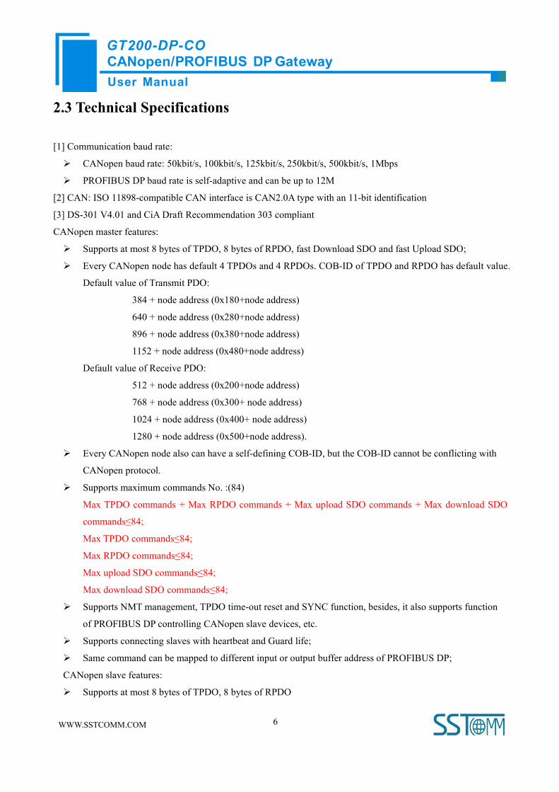
2.3 Technical Specifications
[1] Communication baud rate:
CANopen baud rate: 50kbit/s, 100kbit/s, 125kbit/s, 250kbit/s, 500kbit/s, 1Mbps
PROFIBUS DP baud rate is self-adaptive and can be up to 12M
[2] CAN: ISO 11898-compatible CAN interface is CAN2.0A type with an 11-bit identification
[3] DS-301 V4.01 and CiA Draft Recommendation 303 compliant
CANopen master features:
Supports at most 8 bytes of TPDO, 8 bytes of RPDO, fast Download SDO and fast Upload SDO;
Every CANopen node has default 4 TPDOs and 4 RPDOs. COB-ID of TPDO and RPDO has default value.
Default value of Transmit PDO:
384 + node address (0x180+node address)
640 + node address (0x280+node address)
896 + node address (0x380+node address)
1152 + node address (0x480+node address)
Default value of Receive PDO:
512 + node address (0x200+node address)
768 + node address (0x300+ node address)
1024 + node address (0x400+ node address)
1280 + node address (0x500+node address).
Every CANopen node also can have a self-defining COB-ID, but the COB-ID cannot be conflicting with
CANopen protocol.
Supports maximum commands No. :(84)
Max TPDO commands + Max RPDO commands + Max upload SDO commands + Max download SDO
commands≤84;
Max TPDO commands≤84;
Max RPDO commands≤84;
Max upload SDO commands≤84;
Max download SDO commands≤84;
Supports NMT management, TPDO time-out reset and SYNC function, besides, it also supports function
of PROFIBUS DP controlling CANopen slave devices, etc.
Supports connecting slaves with heartbeat and Guard life;
Same command can be mapped to different input or output buffer address of PROFIBUS DP;
CANopen slave features:
Supports at most 8 bytes of TPDO, 8 bytes of RPDO

User ManualCANopen/PROFIBUS DP GatewayGT200-DP-CO
WWW.SSTCOMM.COM 7
fast Download SDO and fast Upload SDO;
Every CANopen node supports up to 42 TPDOs, 42 RPDOs. COB-ID of TPDO and RPDO has default
value or users can use self-defining COB-ID.
Default value of Transmit PDO:
384 + node address (0x180+node address)
640 + node address (0x280+node address)
896 + node address (0x380+node address)
1152 + node address (0x480+node address);
Default value of Receive PDO:
512 + node address (0x200+node address)
768 + node address (0x300+ node address)
1024 + node address (0x400+ node address)
1280 + node address (0x500+node address).
Support at most 42 TPDO and 42 RPDO;
Timeout clear function of RPDO and delay to start-up;
Supports SDO visiting input and output data exchange area;
Only support Heartbeat;
[4] Work circumstance temperature: -4℉~140℉(-20℃ to 60℃), REL Humidity: 5% to 95% (non-condensing);
[5] Power: 24VDC (11V~30V), maximum 90mA (24V);
[6] External dimensions size (W*H*D): 0.98 in*3.94 in*3.54 in (25mm*100mm*90mm);
[7] Installation: 35mm DIN RAIL;
2.4 Attention
To prevent stress, prevent module panel damage;
To prevent bump, module may damage internal components;
Power supply voltage control in the prospectus, within the scope of the requirements to burn module;
To prevent water, water module will affect the normal work;
Please check the wiring, before any wrong or short circuit.
2.5 Related Products
Related products include:
GT200-DP-CA, GT200-CO-EI and so on
More information about these products, please visit: http://www.sstcomm.com

User ManualCANopen/PROFIBUS DP GatewayGT200-DP-CO
WWW.SSTCOMM.COM 8
2.6 Revision History
Revision Date Chapter Description
REVA 21/2/2017 All First release V5.3, the
same with V5.2 REVA
REVA 3/3/2016 Chapter 5 First release V5.2 user
manual, add function of
SDO Send Concurrently,
Retries of SDO, SDO Poll
Delay Time
User ManualCANopen/PROFIBUS DP GatewayGT200-DP-CO
WWW.SSTCOMM.COM 9
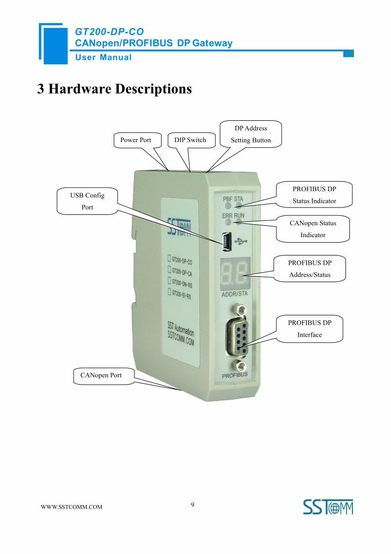
3 Hardware Descriptions
CANopen Port
Power Port
PROFIBUS DP
Interface
PROFIBUS DP
Status Indicator
PROFIBUS DP
Address/Status
CANopen Status
Indicator
DIP Switch
DPAddress
Setting Button
USB Config
Port

User ManualCANopen/PROFIBUS DP GatewayGT200-DP-CO
WWW.SSTCOMM.COM 10
3.1 Indicators
Indicators Status Description
PROFIBUS
Status
PBF
(red)
On PROFIBUS DP connection has not been established
Off PROFIBUS DP connection has been established
STA
(green)
Blinking Exchanging data
Off PROFIBUS DP status is abnormal
CANopen
Status
ERR
(bicolor)
Green on The CAN network is normal
Red on Bus Off
Red, Green and Off
alter alternately
The error counter of CAN controller reach or exceed alarm
value
RUN
(bicolor)
Green on Node is in the run state
Green light on every
200ms, off every
1000ms
Node is in the stop state
Green light on every
200ms, off every
200ms
Node is in the pre-run state
Serial Port
TX Red blinking Serial port is sending data
Red off Connection not established or goes wrong
RX Green blinking Receiving data
Green off Connection not established or goes wrong
3.2 DIP Switch
Run mode to Configuration mode: Set bit2 to ON, the gateway enter into Configuration mode and no need to
restart the gateway (power off and power on).
Off
On 1 2

User ManualCANopen/PROFIBUS DP GatewayGT200-DP-CO
WWW.SSTCOMM.COM 11
Function (1) Mode (2) Description
Off Off Run Mode, allow setting DP address
Off On Configuration Mode
On OffRun mode with debug function, not allow
setting DP address
On OnRun Mode, prohibit setting DP address
(Locked)
Notes: Except for the Locked status, the switch of other three statuses, no need to restart the gateway.
3.3 Communication Interface
3.3.1 PROFIBUS DPConnector
PROFIBUS DP interface uses DB9 connector, and the pins are defined as follows:
DB9 pin Function
3 PROFI_B, Data positive
5 GND (optional)
8 PROFI_A, Data negative
3.3.2 CANopen Connector
5-pin connector:
5
1
PROFI_A (Pin 8)
GND (Pin 5)
PROFI_B (Pin 3)

User ManualCANopen/PROFIBUS DP GatewayGT200-DP-CO
WWW.SSTCOMM.COM 12
V+GND CAN-L
Shield
CAN-H
5 1
Open five-pin connector at the side of CAN:
Pin Connection
1 V+ (Optional)
2 CAN-H
3 Shield (Optional)
4 CAN-L
5 GND
Note 1: Connections of V+ and shield are optional, but connections of CAN-H, CAN-L and GND are necessary;
Note 2: GND, V+ of CANopen interface interlinks V+, GND of power interface internally. You can only power on
one of the two interfaces.
3.4 Other Interface
3.4.1 Power Interface
Note 1: 24V+, GND of power interface interlinks V+, GND of CANopen interface. You can only power on one of
the two interfaces.

User ManualCANopen/PROFIBUS DP GatewayGT200-DP-CO
WWW.SSTCOMM.COM 13
3.4.2 LED Display
In the configuration mode, LED display CF;
In the debug mode, LED displays “db”;
In the run mode, LED displays PROFIBUS DP slave address.
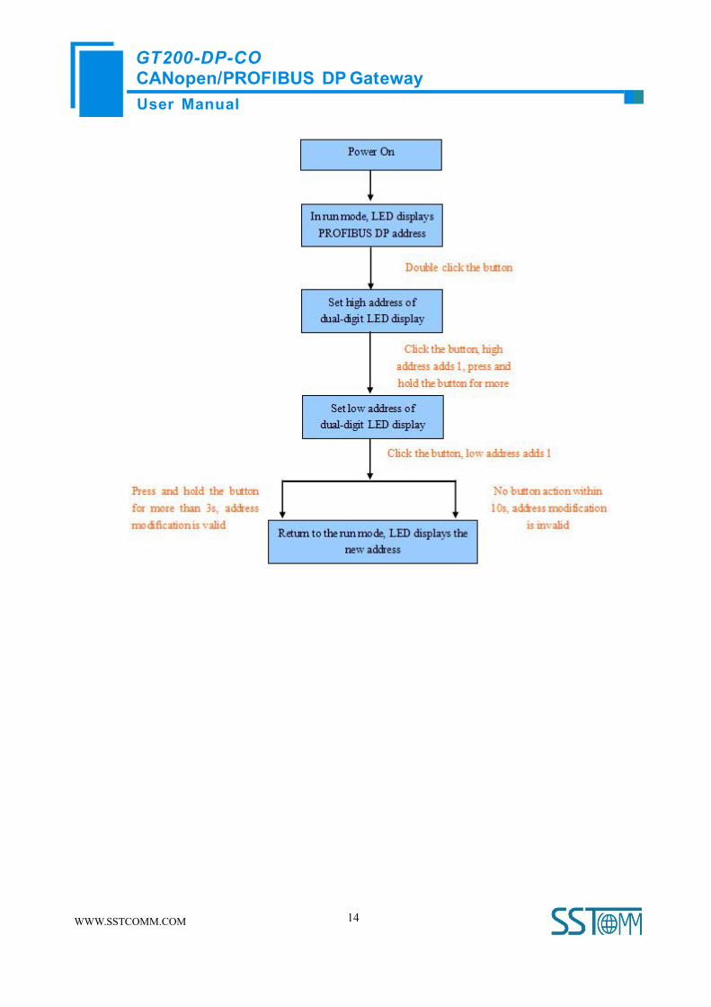
3.4.3 PROFIBUS DPAddress Setting Button
The configuration button on the panel can set the PROFIBUS DP slave address.
In run mode of GT200-DP-CO, LED display is always on and displaying the current PROFIBUS DP address.
Quickly press (double-click) the button twice in succession, the high bit starts to flash, and the low bit is always
on, click the button to add 1 to start setting the high bit of PROFIBUS DP address. Long-press the button for 3
seconds, the high bit is always on, and the low bit starts to flash. Click the button to add 1 to start setting the low
bit of PROFIBUS DP address. At last, long-press the button again for 3 seconds, the address flashing three times
shows that the address is set successfully. If no button action within ten seconds, the gateway exits the status of
setting address and continues to display the original address. The configurable range of PROFIBUS DP address is
0 to 99 (Decimal).
PROFIBUS DP address setting method is as follow:
User ManualCANopen/PROFIBUS DP GatewayGT200-DP-CO
WWW.SSTCOMM.COM 14
User ManualCANopen/PROFIBUS DP GatewayGT200-DP-CO
WWW.SSTCOMM.COM 15
4 Use Method
4.1 Quick Start Guide
1. This gateway has two modes: configuration mode and run mode, you can select different mode through DIP
switch. Set “mode” bit of DIP switch to “on”, the gateway is in the configuration mode, and turn off the “mode”
bit, the gateway is in the run mode;
2. Use USB cable to connect to the USB port of PC and set “mode” bit of DIP switch to “on”, then power on the
device;
3. In the configuration mode, set CANopen baud rate, CANopen node ID, SDO commands (CANopen master
mode), PDO commands and data mapping between CANopen and PROFIBUS DP through gateway configuration
software SST-CP-CFG. (See chapter 4.3 for details).
4. Set "mode" bit of DIP switch to “off” state, configure PROFIBUS DP address through DP address setting
button, power on again and the module go into run mode.
5. Set the address of the PROFIBUS DP by pressing the button, note that this address must be the same as the
address of this slave in the DP master configuration; otherwise DP connection will be failed.
6. In run mode, users can debug data in input and output buffer through setting “function” bit of DIP switch to
“ON” status. Users can see the data in debug interface of SST-CP-CFG through USB interface; Users can use the
function at the beginning of network communication, when the network is OK, please close the debug function,
that is to set “function” bit of DIP switch to “off”.
4.2 Hardware Wiring
1. According to the PROFIBUS port instructions, properly connect with DB9. It is suggested to use standard
PROFIBUS DP connector.
2. According to the CAN port instructions, properly connect the pin 2 and 4 at least.
3. Check all connections whether they comply with the instructions.
4. Set “mode” bit of DIP switch to “Off”, power on the module, and the module go into run status.
User ManualCANopen/PROFIBUS DP GatewayGT200-DP-CO
WWW.SSTCOMM.COM 16
4.3 Run
4.3.1 Data Exchange Mode
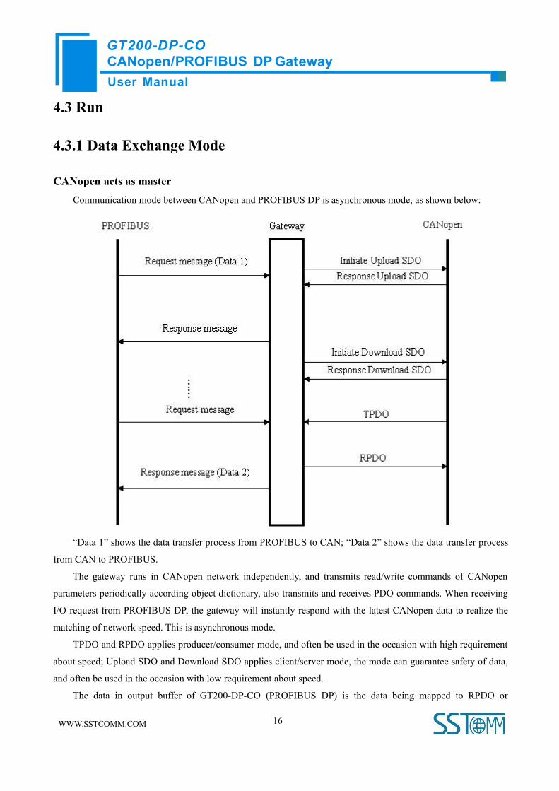
CANopen acts as masterCommunication mode between CANopen and PROFIBUS DP is asynchronous mode, as shown below:
“Data 1” shows the data transfer process from PROFIBUS to CAN; “Data 2” shows the data transfer process
from CAN to PROFIBUS.
The gateway runs in CANopen network independently, and transmits read/write commands of CANopen
parameters periodically according object dictionary, also transmits and receives PDO commands. When receiving
I/O request from PROFIBUS DP, the gateway will instantly respond with the latest CANopen data to realize the
matching of network speed. This is asynchronous mode.
TPDO and RPDO applies producer/consumer mode, and often be used in the occasion with high requirement
about speed; Upload SDO and Download SDO applies client/server mode, the mode can guarantee safety of data,
and often be used in the occasion with low requirement about speed.
The data in output buffer of GT200-DP-CO (PROFIBUS DP) is the data being mapped to RPDO or
User ManualCANopen/PROFIBUS DP GatewayGT200-DP-CO
WWW.SSTCOMM.COM 17
Download SDO commands of CANopen slave. Outputting mode of GT200-DP-CO is change of value, that is,
until the DP output data is changed, GT200-DP-CO transmits corresponding commands (RPDO or Download
SDO) to CANopen network; For DP input data, GT200-DP-CO receives data through TPDO or Upload SDO
commands configured in the configuration software SST-CP-CFG and save the data to DP input buffer.
When the “Control&Status” bit is “Enable” in configuration software (SST-CP-CFG), there are two bytes in
the end of input and output buffer of GT200-DP-CO showing status of CANopen slaves and controlling status of
CANopen slave.
The last two bytes of input buffer (PROFIBUS DP) shows the status of CANopen slaves. The first byte of
this two bytes is address of CANopen slave and the second byte is status of CANopen slave (i.e. Pre-run status,
run status, stop status, for detailed information, please refer to CANopen protocol). One time it only shows status
of one CANopen slave, GT200-DP-CO applies FIFO mechanism to save all status of every CANopen slave and
output to PROFIBUS DP master in FIFO order.
The last two bytes of output buffer (PROFIBUS DP) is the status that DP master controls CANopen slaves.
The first byte of this two bytes is address of CANopen slave, the second byte is command controlling CANopen
slave (i.e. go into pre-run status, go into run status, go into stop status, reset node, reset application and reset
communication, for specific command format, please refer to NMT of CANopen protocol).
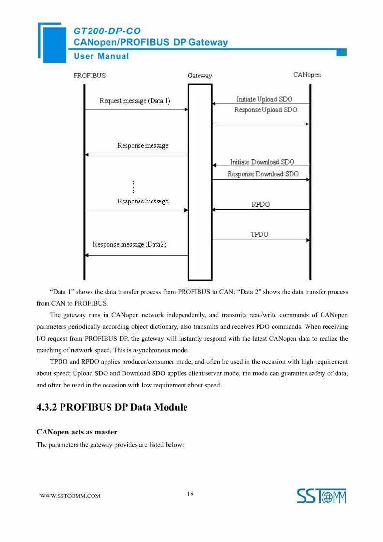
CANopen acts as slaveCommunication mode between CANopen and PROFIBUS DP is asynchronous mode, as shown below:
User ManualCANopen/PROFIBUS DP GatewayGT200-DP-CO
WWW.SSTCOMM.COM 18
“Data 1” shows the data transfer process from PROFIBUS to CAN; “Data 2” shows the data transfer process
from CAN to PROFIBUS.
The gateway runs in CANopen network independently, and transmits read/write commands of CANopen
parameters periodically according object dictionary, also transmits and receives PDO commands. When receiving
I/O request from PROFIBUS DP, the gateway will instantly respond with the latest CANopen data to realize the
matching of network speed. This is asynchronous mode.
TPDO and RPDO applies producer/consumer mode, and often be used in the occasion with high requirement
about speed; Upload SDO and Download SDO applies client/server mode, the mode can guarantee safety of data,
and often be used in the occasion with low requirement about speed.
4.3.2 PROFIBUS DPData Module
CANopen acts as masterThe parameters the gateway provides are listed below:

User ManualCANopen/PROFIBUS DP GatewayGT200-DP-CO
WWW.SSTCOMM.COM 19
Number Input Output Instance
1 112 bytes 112 bytes
2 96 bytes 96 bytes
3 48 bytes 48 bytes
4 16 bytes 16 bytes
5 Setting through Hardware Configuration of PROFIBUS DP
Configure fixed input and output bytes in the software:
The data module of length consistent GT200-DP-CO supports is listed below:
16 Byte In, 16 Byte Out: one 8 words Consistent
96 Byte In, 96 Byte Out: three 16 words Consistent
During Step7 programming, it needs to use package sending and receiving. Package sending and receiving
mainly adopts SFC15 (package sending) and SFC14 (package receiving). (Please refer to chapter 5 for details)
The data module of byte consistent GT200-DP-CO supports is listed below:
48 Byte In, 48 Byte Out
The data module of word consistent GT200-DP-CO supports is listed below:
112 Byte In, 112 Byte Out
For the data module of byte and word consistent, users can use MOVE command to read/write data during
Step7 programming.
User ManualCANopen/PROFIBUS DP GatewayGT200-DP-CO
WWW.SSTCOMM.COM 20
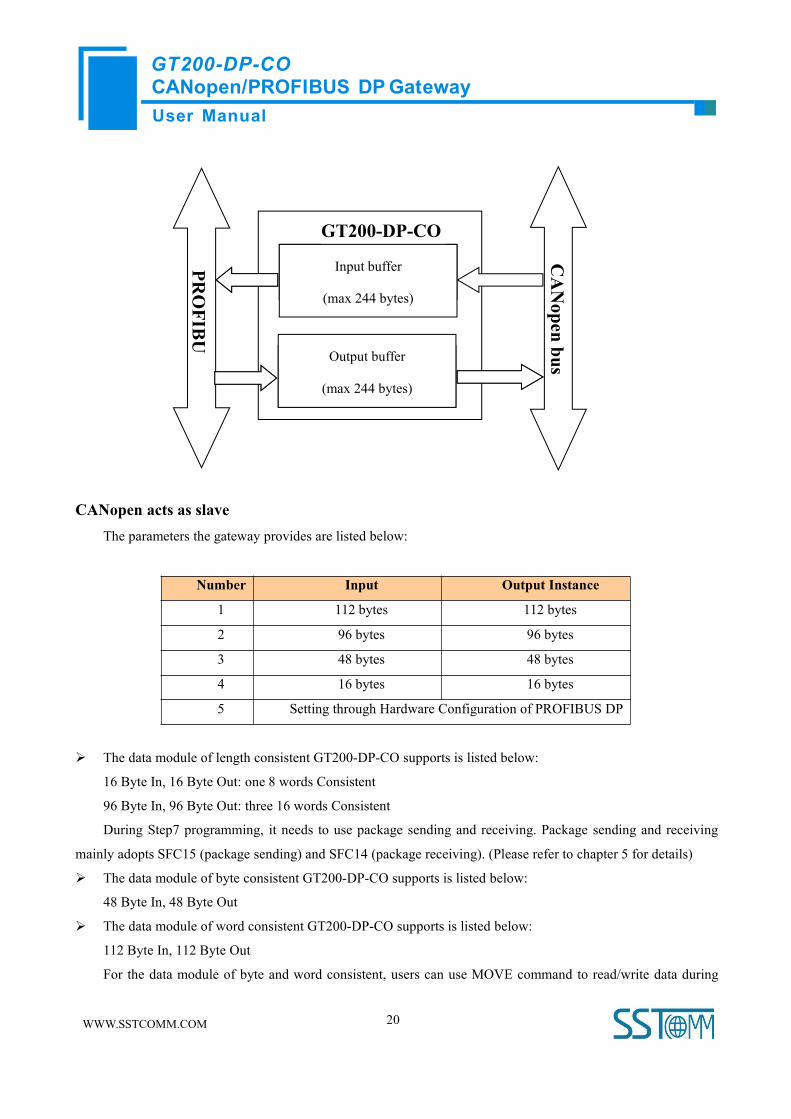
CANopen acts as slaveThe parameters the gateway provides are listed below:
Number Input Output Instance
1 112 bytes 112 bytes
2 96 bytes 96 bytes
3 48 bytes 48 bytes
4 16 bytes 16 bytes
5 Setting through Hardware Configuration of PROFIBUS DP
The data module of length consistent GT200-DP-CO supports is listed below:
16 Byte In, 16 Byte Out: one 8 words Consistent
96 Byte In, 96 Byte Out: three 16 words Consistent
During Step7 programming, it needs to use package sending and receiving. Package sending and receiving
mainly adopts SFC15 (package sending) and SFC14 (package receiving). (Please refer to chapter 5 for details)
The data module of byte consistent GT200-DP-CO supports is listed below:
48 Byte In, 48 Byte Out
The data module of word consistent GT200-DP-CO supports is listed below:
112 Byte In, 112 Byte Out
For the data module of byte and word consistent, users can use MOVE command to read/write data during
Input buffer 112/96/48/16
bytes
PROFIB
U
GT200-DP-COCANopen
busOutput buffer 112/96/48/16
bytes
Input buffer
(max 244 bytes)
Output buffer
(max 244 bytes)

User ManualCANopen/PROFIBUS DP GatewayGT200-DP-CO
WWW.SSTCOMM.COM 21
Step7 programming.
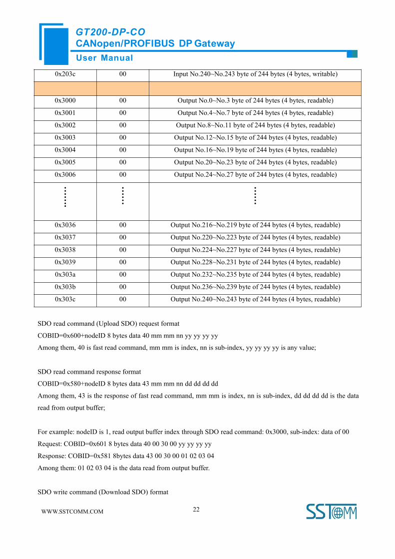
Input, output buffer support fast SDO visit, the location where input/output buffer is located in is listed below:
Index Sub-index Description
0x2000 00 Input No.0~No.3 byte of 224 bytes (4 bytes, writable)
0x2001 00 Input No.4~No.7 byte of 224 bytes (4 bytes, writable)
0x2002 00 Input No.8~No.11 byte of 224 bytes (4 bytes, writable)
0x2003 00 Input No.12~No.15 byte of 224 bytes (4 bytes, writable)
0x2004 00 Input No.16~No.19 byte of 224 bytes (4 bytes, writable)
0x2005 00 Input No.20~No.23 byte of 224 bytes (4 bytes, writable)
0x2006 00 Input No.24~No.27 byte of 224 bytes (4 bytes, writable)
…….
……
……
0x2036 00 Input No.216~No.219 byte of 244 bytes (4 bytes, writable)
0x2037 00 Input No.220~No.223 byte of 244 bytes (4 bytes, writable)
0x2038 00 Input No.224~No.227 byte of 244 bytes (4 bytes, writable)
0x2039 00 Input No.228~No.231 byte of 244 bytes (4 bytes, writable)
0x203a 00 Input No.232~No.235 byte of 244 bytes (4 bytes, writable)
0x203b 00 Input No.236~No.239 byte of 244 bytes (4 bytes, writable)
Input buffer
(max 244 bytes)
GT200-DP-CO
Output buffer
(max 244 bytes)
PROFIB
US
CANopen
bus
User ManualCANopen/PROFIBUS DP GatewayGT200-DP-CO
WWW.SSTCOMM.COM 22
0x203c 00 Input No.240~No.243 byte of 244 bytes (4 bytes, writable)
0x3000 00 Output No.0~No.3 byte of 244 bytes (4 bytes, readable)
0x3001 00 Output No.4~No.7 byte of 244 bytes (4 bytes, readable)
0x3002 00 Output No.8~No.11 byte of 244 bytes (4 bytes, readable)
0x3003 00 Output No.12~No.15 byte of 244 bytes (4 bytes, readable)
0x3004 00 Output No.16~No.19 byte of 244 bytes (4 bytes, readable)
0x3005 00 Output No.20~No.23 byte of 244 bytes (4 bytes, readable)
0x3006 00 Output No.24~No.27 byte of 244 bytes (4 bytes, readable)
…….
……
……
0x3036 00 Output No.216~No.219 byte of 244 bytes (4 bytes, readable)
0x3037 00 Output No.220~No.223 byte of 244 bytes (4 bytes, readable)
0x3038 00 Output No.224~No.227 byte of 244 bytes (4 bytes, readable)
0x3039 00 Output No.228~No.231 byte of 244 bytes (4 bytes, readable)
0x303a 00 Output No.232~No.235 byte of 244 bytes (4 bytes, readable)
0x303b 00 Output No.236~No.239 byte of 244 bytes (4 bytes, readable)
0x303c 00 Output No.240~No.243 byte of 244 bytes (4 bytes, readable)
SDO read command (Upload SDO) request format
COBID=0x600+nodeID 8 bytes data 40 mm mm nn yy yy yy yy
Among them, 40 is fast read command, mm mm is index, nn is sub-index, yy yy yy yy is any value;
SDO read command response format
COBID=0x580+nodeID 8 bytes data 43 mm mm nn dd dd dd dd
Among them, 43 is the response of fast read command, mm mm is index, nn is sub-index, dd dd dd dd is the data
read from output buffer;
For example: nodeID is 1, read output buffer index through SDO read command: 0x3000, sub-index: data of 00
Request: COBID=0x601 8 bytes data 40 00 30 00 yy yy yy yy
Response: COBID=0x581 8bytes data 43 00 30 00 01 02 03 04
Among them: 01 02 03 04 is the data read from output buffer.
SDO write command (Download SDO) format

User ManualCANopen/PROFIBUS DP GatewayGT200-DP-CO
WWW.SSTCOMM.COM 23
COBID=0x600+nodeID 8 bytes data 23 mm mm nn dd dd dd dd
Among them, 23 is fast read command, mm mm is index, nn is sub index, dd dd dd dd is the data needs to be
written to input buffer;
SDO write command format
COBID=0x580+nodeID 8 bytes data 60 mm mm nn 00 00 00 00
Among them, 60 is fast write response, mm mm is index, nn is sub index, 00 00 00 00 is default value;
For example, nodeID is 1, write data (01 02 03 04) to input buffer index through SDO write command: 0x2000,
sub index: 00
Request: COBID=0x601 8 bytes data 23 00 20 00 01 02 03 04
Response: COBID=0x581 8bytes data 60 00 20 00 00 00 00 00
Among them: 01 02 03 04 is the data needs to be written to input buffer.
When CANopen side is salve, it supports visiting error register to estimate PROFIBUS communication state
through SDO:
SDO read command request format that CANopen master sent
COBID=0x600+nodeID 8bytes data 40 01 10 00 yy yy yy
Among them, 40 is fast read command, 0x1001 is index, 00 is sub index, yy yy yy yy is any value.
SDO read command request format that CANopen slave sent:
COBID=0x580+nodeID 8 bytes data 4f 01 10 00 00 yy yy yy yy (00 means PROFIBUS is not off)
4f 01 10 00 80 yy yy yy yy (80 means PROFIBUS is off)
Among them, 4f is fast read command response, 0x1001 is index, 00 is sub index, yy yy yy is any value.
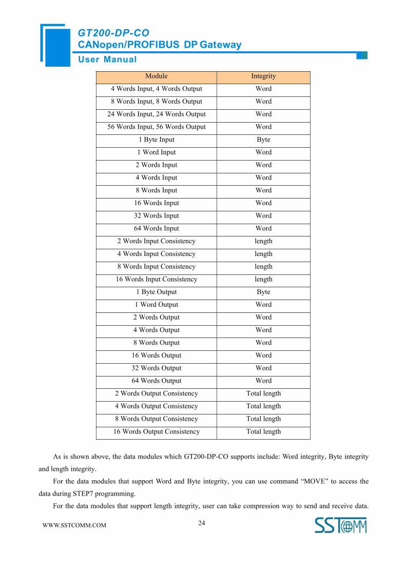
4.3.3 How Step7 Read and Write Gateway Data
When you choose “Setting through Hardware Configuration of PROFIBUS DP” in the configuration
software SST-CP-CFG, you muse refer to this chapter. GT200-DP-CO provides new modules shown as below.
The maximum allowed number of modules is 64 in Step7. The maximum allowed number of input bytes is 244,
the max number of output bytes is 244 and the aggregate of maximum number of input bytes and output bytes is
488.
User ManualCANopen/PROFIBUS DP GatewayGT200-DP-CO
WWW.SSTCOMM.COM 24
Module Integrity
4 Words Input, 4 Words Output Word
8 Words Input, 8 Words Output Word
24 Words Input, 24 Words Output Word
56 Words Input, 56 Words Output Word
1 Byte Input Byte
1 Word Input Word
2 Words Input Word
4 Words Input Word
8 Words Input Word
16 Words Input Word
32 Words Input Word
64 Words Input Word
2 Words Input Consistency length
4 Words Input Consistency length
8 Words Input Consistency length
16 Words Input Consistency length
1 Byte Output Byte
1 Word Output Word
2 Words Output Word
4 Words Output Word
8 Words Output Word
16 Words Output Word
32 Words Output Word
64 Words Output Word
2 Words Output Consistency Total length
4 Words Output Consistency Total length
8 Words Output Consistency Total length
16 Words Output Consistency Total length
As is shown above, the data modules which GT200-DP-CO supports include: Word integrity, Byte integrity
and length integrity.
For the data modules that support Word and Byte integrity, you can use command “MOVE” to access the
data during STEP7 programming.
For the data modules that support length integrity, user can take compression way to send and receive data.

User ManualCANopen/PROFIBUS DP GatewayGT200-DP-CO
WWW.SSTCOMM.COM 25
The compression way mainly uses “SFC 15” when sending and receiving uses “SFC 14”:
4.3.4 How Step7 Select Data Module
Generally, when the data modules include “Consistent”, this means this data module is length integrity. When
accessing data, you need to use SFC14 (read) and SFC15 (write) to read or write data. And those which didn’t
include “Consistent”, you can use “Move” command to access the data.
According to user’s demand of input/output bytes, there are so many alternatives for the selection of data
modules. For example: When user needs 20-words input ( The data number reading form Modbus slave through
PLC is 20 words), user can directly select data modules no less than 20 words input (32words Input、64words
Input…) or input one input/output modules no less than 20 words (56 words Input,56words Output…).
Take “2 words Input Consistent” as an example, when you choose the module, you must use “SFC 14” to
access the data address. When some data of Modbus slave is two-word data, and needs high accuracy and real-
time, user generally select “2 words Input Consistent”, and not to select “2 words Input”. So, PLC can access the
whole data module during reading data, and it can also prevent data from burst changing (last word data and next
word data are not read in the same time) and causing incorrect data.
User ManualCANopen/PROFIBUS DP GatewayGT200-DP-CO
WWW.SSTCOMM.COM 26
5 Software Instructions
Users can use connect GT200-DP-CO to the PC with USB port and configure gateway’s relevant parameters
through SST-CP-CFG, including CANopen address, CAN baud rate and input/output data mapping bytes number
from CANopen network to PROFIBUS.
Configuring steps:
5.1 CANopen Acts as Master
5.1.1 Notes before Configuration
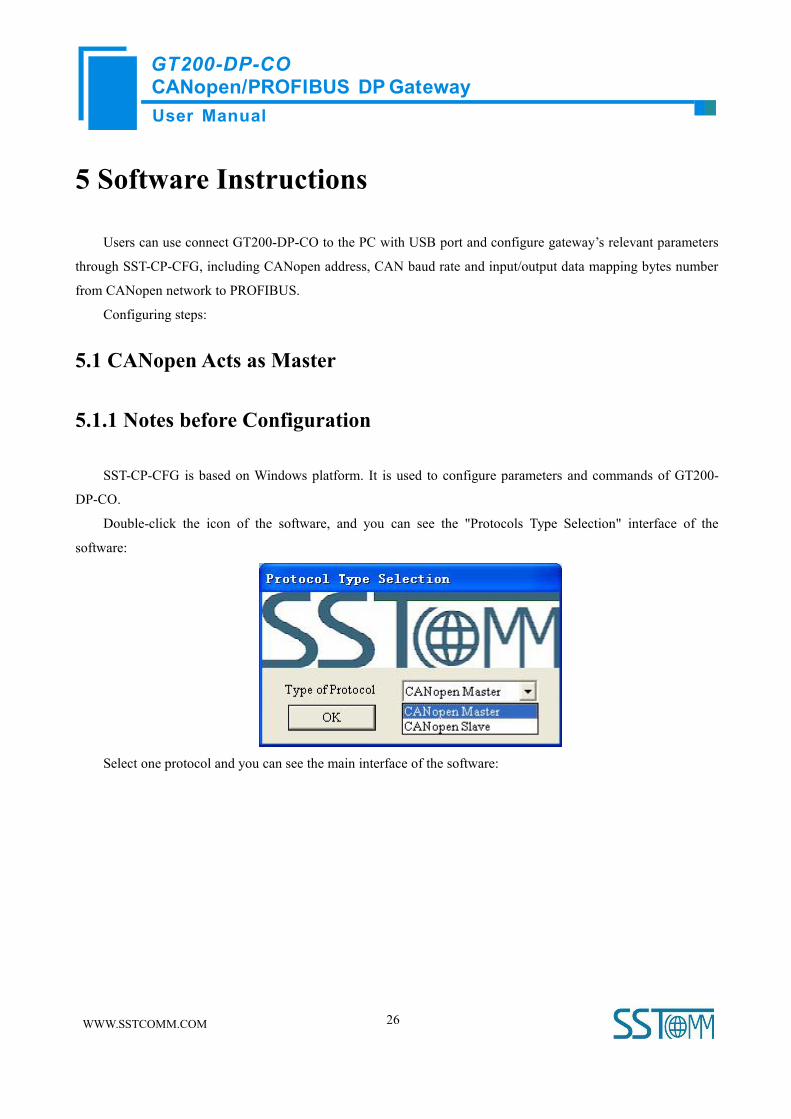
SST-CP-CFG is based on Windows platform. It is used to configure parameters and commands of GT200-
DP-CO.
Double-click the icon of the software, and you can see the "Protocols Type Selection" interface of the
software:
Select one protocol and you can see the main interface of the software:
User ManualCANopen/PROFIBUS DP GatewayGT200-DP-CO
WWW.SSTCOMM.COM 27
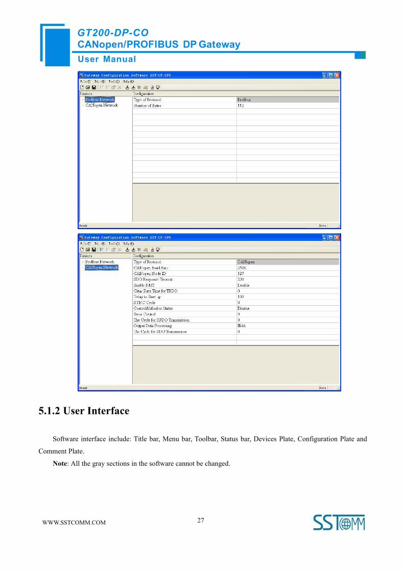
5.1.2 User Interface
Software interface include: Title bar, Menu bar, Toolbar, Status bar, Devices Plate, Configuration Plate and
Comment Plate.
Note: All the gray sections in the software cannot be changed.

User ManualCANopen/PROFIBUS DP GatewayGT200-DP-CO
WWW.SSTCOMM.COM 28
Toolbar:
Toolbar is shown as below:
The function of Toolbar: New, Open, Save, Add Node, Delete Node, Add Command, Delete Command,
Upload, Download, Mapping Address Conflict Detection, Calculate Mapping Address, Export EXCEL and
Monitor.
New: Create a new configuration project
Open: Open a configuration project
Save: Save current configuration
Add Node: Add a node for CANopen master
Delete Node: Delete a node for CANopen master
Add Command: Add a CANopen command
Delete Command: Delete a CANopen command
Upload: Read the configuration information from the module and shown in the software
Download: Download the configuration file to the gateway
Mapping Address Conflict Detection: To check whether there are some conflicts with configured commands in
the gateway memory data buffer
Toolbar
Device plate: Users can select
operation objects including
Profibus network and
CANopen Network, and adding
nodes and commands
Menu Bar Title Bar
Configuration plate:
Input configuration parameters,
gray parts cannot be changed
Comment plate: Explain
the function of the
configuration options

User ManualCANopen/PROFIBUS DP GatewayGT200-DP-CO
WWW.SSTCOMM.COM 29
Calculate Mapping Address: Used to automatically calculate the mapped memory address without conflict by
each command
Export EXCEL: Export current configuration to the local hard disk, saved as .xls file
Monitor: Monitor the gateway memory buffer data
5.1.3 Device View Operation
5.1.3.1 Device View Interface
5.1.3.2 Operation ModeSupport three kinds of operation modes: edit menu, edit toolbar, and right-click edit menu.

User ManualCANopen/PROFIBUS DP GatewayGT200-DP-CO
WWW.SSTCOMM.COM 30
5.1.3.3 Operation Types1) Add node: Left click on CANopen Network or existing nodes, and then perform the operation of adding a new
node. Then there is a new node named "New node" under CANopen Network.
2) Delete node: Left click on the node to be deleted, and then perform the operation of deleting node. The node
and all commands will be deleted.
3) Add commands: Left click on the node, and then perform the operation of adding command to add a command
for the node. It will pop up the command selecting dialog box for users to choose. Shown as below:
Commands: Upload SDO->Profibus In, Download SDO <-Profibus Out, Transmit PDO->Profibus In, Receive
PDO<-Profibus Out
Select commands: Double click a command (Take command selection under CANopen master mode as an
example)
4) Delete command: Left click a command and you can delete it.
5) Copy node: Left click on the existing node, choose the node and execute the operation of copying nodes
(include all commands under the node)
6) Paste node: Left click and choose any existing node, execute operation of pasting node. Then under the Modbus
TCP tree you can see a new node (include all commands under the node); Parameters of new node is default
User ManualCANopen/PROFIBUS DP GatewayGT200-DP-CO
WWW.SSTCOMM.COM 31
setting, it needs to be reset.
5.1.4 Configuration View Operation
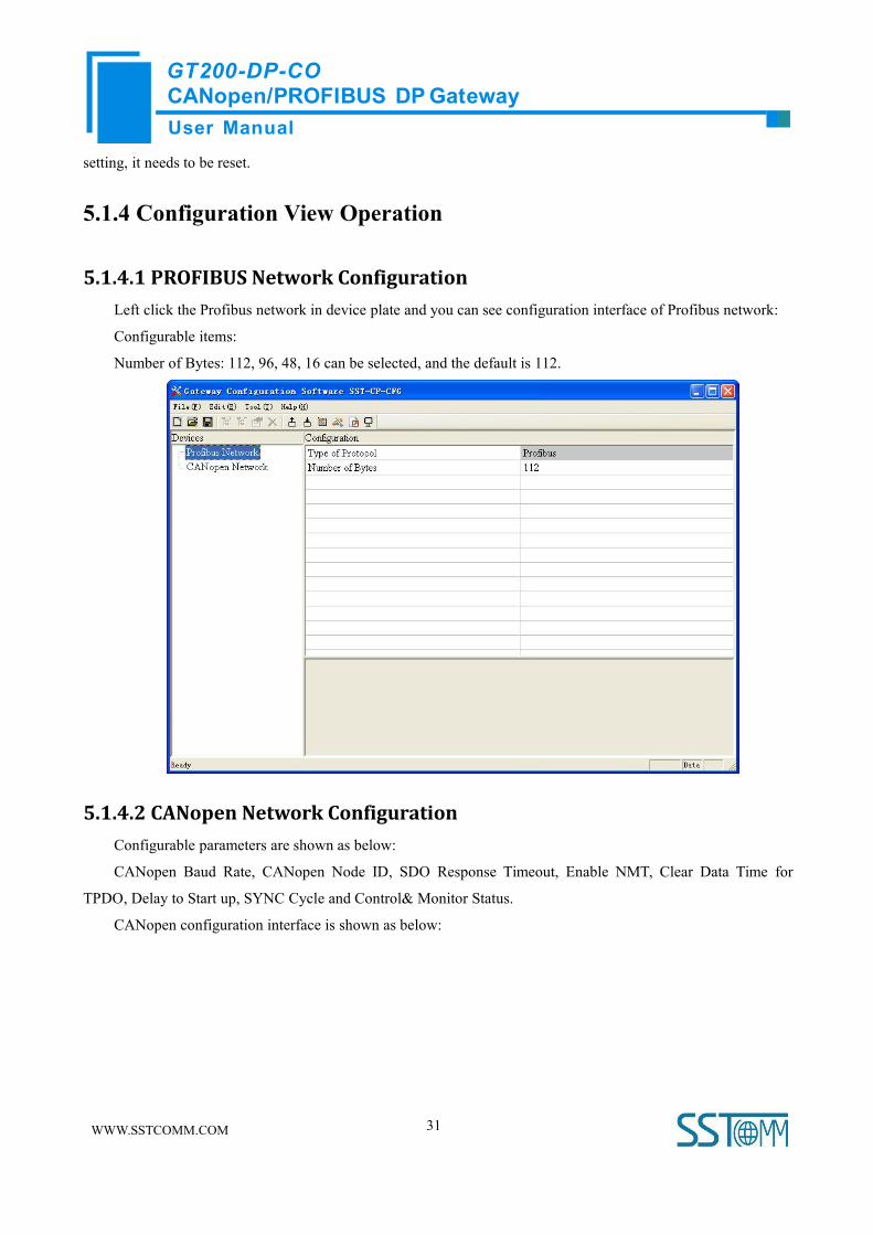
5.1.4.1 PROFIBUS Network ConfigurationLeft click the Profibus network in device plate and you can see configuration interface of Profibus network:
Configurable items:
Number of Bytes: 112, 96, 48, 16 can be selected, and the default is 112.
5.1.4.2 CANopen Network ConfigurationConfigurable parameters are shown as below:
CANopen Baud Rate, CANopen Node ID, SDO Response Timeout, Enable NMT, Clear Data Time for
TPDO, Delay to Start up, SYNC Cycle and Control& Monitor Status.
CANopen configuration interface is shown as below:

User ManualCANopen/PROFIBUS DP GatewayGT200-DP-CO
WWW.SSTCOMM.COM 32
CANopen Baud Rate: 50K, 100K, 125K, 250K, 500K, 1M can be selected; the default value is 250K
CANopen Node ID: 1 to127, the default value is 1
SDO Response Timeout: This parameter is based on 10 milliseconds. The range of the parameter value is 1 to
2000. Default value is 200
Enable NMT: Whether to start all CANopen nodes on the network or not, the default is disable
Clear Data Time for TPDO: TPDO timeout value
0: Do not use the function;
Nonzero value: Use timeout function and the timeout value is nonzero integral multiple of 10 milliseconds,
the range is 0 to 2000, the default is 0
Delay to start up: Delay value
0: Do not use the function;
Nonzero value: Use the function, and delay value is nonzero integral multiple of 10 milliseconds, the range is
0 to 2000, the default is 100. When the value of "Enable NMT" is "Enable", the parameter is valid.
SYNC: Synchronizing cycle
0: Do not use synchronizing cycle function
Nonzero value: Use the function, and the synchronizing cycle is nonzero integral multiple of 10 milliseconds,
the range is 1 to 2000, the default is 0
Control& Monitor Status: The first two bytes of output buffer is used as status byte of CANopen slave. The
first byte of this two byte is address of CANopen salve, and the second byte is the command which controls
CANopen slave. Selecting "Enable", SST-CP-CFG will minus two bytes when calculating mapping address
automatically and this two byte are saved in the end of buffer.

User ManualCANopen/PROFIBUS DP GatewayGT200-DP-CO
WWW.SSTCOMM.COM 33
Errol Control: Function selection item. Non-zero means to use life guard protocol. Zero means to use
heartbeat protocol. The default is 0. The range is 0~2000.
The Cycle for RPDO Transmission: The Cycle for RPDO Transmission is based on 1ms. Zero means to use
the mode of change of value output; Non-zero means to send all RPDO according to the cycle. Sending cycle
equals setting value, the default value is 0. The range: 0~60000.
Output Data Processing: When PROFIBUS DP is off, the RPDO data of DP output buffer will Clear and
Hold; “Clear” means to set the data to zero; “Hold” means to keep the data unchanged before DP is off.
The Cycle for SDO Transmission: The Cycle for SDO Transmission, is based on 1ms. Zero means Download
SDO uses mode of change of value output, Upload SDO uses the mode of non-stop reading slave data; Non-
zero means to send all SDO according to the cycle. Sending cycle equals setting value, the default value is 0.
The range: 0~60000.
SDO Send Concurrently: Disable: The SDO request for a node must wait for the node’s response before
initiating the next SDO request; Enable: Sending SDOs command requests of different nodes concurrently.
Retries of SDO: The CANopen master sends an SDO request command but does not receive a response from
the slave, and the master repeatedly sends this SDO request command. Range: 0~5, default: 0
SDO Poll Delay Time: The CANopen master sends the SDO request command and receives the response
from the slave. The master needs to delay for a while before sending the next SDO request command. This
period of time is the SDO command polling delay time. Unit: ms, Range: 0~60000ms, default: 0ms.
5.1.4.3 Node ConfigurationIn the device interface, left click on a node and then the configuration interface is shown as below:

User ManualCANopen/PROFIBUS DP GatewayGT200-DP-CO
WWW.SSTCOMM.COM 34
5.1.4.4 Command ConfigurationIn the device interface, left click on a command and then the configuration interface is shown as below:
Slave address: CANopen slave address, the range is 1 to127
Index value: Object index value in object dictionary (decimal)
Sub-index value: Object sub-index value in object dictionary (decimal)

User ManualCANopen/PROFIBUS DP GatewayGT200-DP-CO
WWW.SSTCOMM.COM 35
Number of bytes: Number of bytes of mapping item
Mapping address: Memory address mapped in the gateway (Read only)
COB-ID: The CAN ID (decimal) of CANopen PDO:
Default value of Transmit PDO command: 384(0x180) + node ID or 640(0x280) + node ID or 896 (0x380) +
node ID or 1152(0x480) + node ID
Default value of Receive PDO: 512(0x200) + node ID or 768(0x300) + node ID or 1024 (0x400) + node ID
or 1280 (0x500) + node ID
Mnemonic description: Users can input the description of project configuration items here; these are not
downloaded to gateway actually
5.1.4.5 Comment InterfaceComment interface displays the explanation of relevant configuration item. When the configuration item is
"COB-ID", the comment interface is shown as below:
5.1.5 Hardware Configuration
Communication menu is shown as below:
5.1.5.1 COM ConfigurationThe software can scan usable serial port automatically, and show it in the port list. Finish all configurations,
click "OK" and save settings.
Remark: When you finish setting port, and other parameters are fixed value: 57600, 8, ODD, 8, 1.

User ManualCANopen/PROFIBUS DP GatewayGT200-DP-CO
WWW.SSTCOMM.COM 36
5.1.5.2 UploadSelect "Upload", it will read configurations form the gateway, and the interface is shown as below:
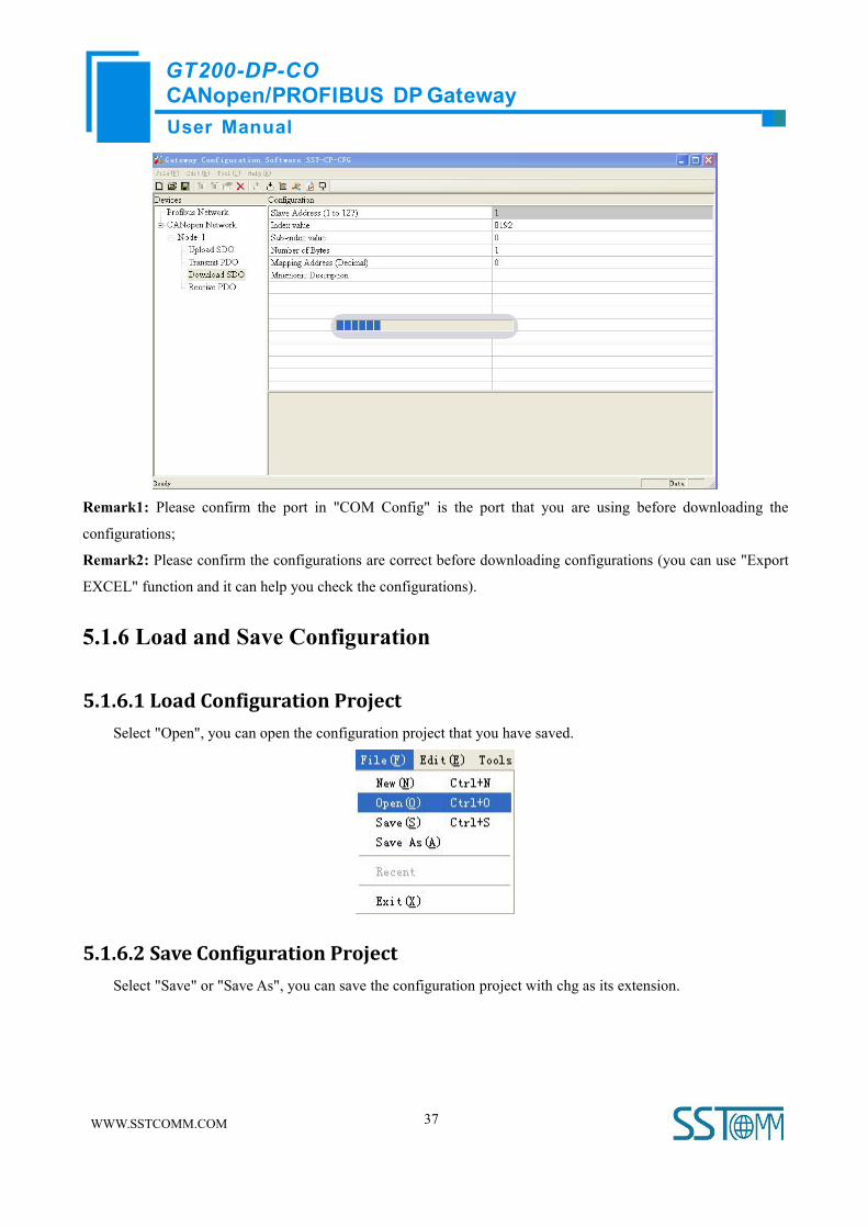
5.1.5.3 DownloadSelect "Download", it will download configurations to the gateway, and the interface is shown as below:
User ManualCANopen/PROFIBUS DP GatewayGT200-DP-CO
WWW.SSTCOMM.COM 37
Remark1: Please confirm the port in "COM Config" is the port that you are using before downloading the
configurations;
Remark2: Please confirm the configurations are correct before downloading configurations (you can use "Export
EXCEL" function and it can help you check the configurations).
5.1.6 Load and Save Configuration
5.1.6.1 Load Configuration ProjectSelect "Open", you can open the configuration project that you have saved.
5.1.6.2 Save Configuration ProjectSelect "Save" or "Save As", you can save the configuration project with chg as its extension.

User ManualCANopen/PROFIBUS DP GatewayGT200-DP-CO
WWW.SSTCOMM.COM 38
5.1.7 Auto Mapping
The mapping address of every command in the gateway must be calculated by fixed formula, users can use
"Calculate Mapping Address" to calculate mapping address automatically.
5.1.8 Export Excel File
Users can use the function to check the gateway configurations.
Select "Export EXCEL", you can save the configuration with .xls as its extension.
5.1.9 Monitor
When the first bit of DIP switch of GT200-DP-CO is set to "ON" status and the second bit is dialed to "OFF"
status, GT200-DP-CO is in the debug mode.
This function can monitor the data in the input buffer of gateway memory; the interface is shown as below:

User ManualCANopen/PROFIBUS DP GatewayGT200-DP-CO
WWW.SSTCOMM.COM 39
There are no data in the buffer and the interface is shown as below:
Users can click "Save content" button and save the data to disk of computer:
After using "Save content", the button will change to "Stop saving", click the button and you can cancel
saving the data to disk of computer:
When users click "Stop Displaying" button, it will stop showing the data in buffer:

User ManualCANopen/PROFIBUS DP GatewayGT200-DP-CO
WWW.SSTCOMM.COM 40
After using "Stop Displaying", the button will change to "Continue to display", click the button it will clear
the items before and show new contents again.
5.2 CANopen Acts as Slave
5.2.1 Notes before Configuration
Select one protocol and you can see the main interface of the software:
User ManualCANopen/PROFIBUS DP GatewayGT200-DP-CO
WWW.SSTCOMM.COM 41
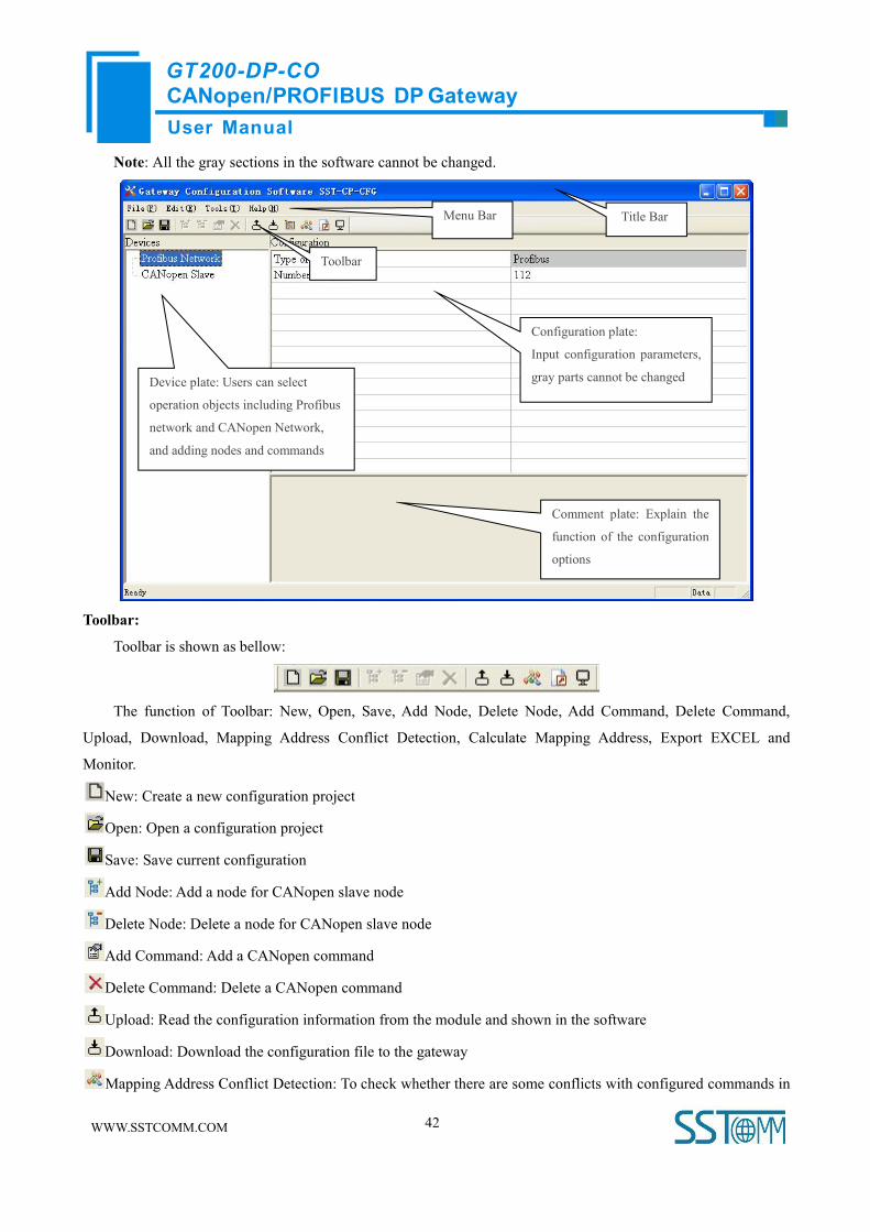
5.2.2 User Interface
Software interface include: Title bar, Menu bar, Toolbar, Status bar, Devices Plate, Configuration Plate and
Comment Plate.
User ManualCANopen/PROFIBUS DP GatewayGT200-DP-CO
WWW.SSTCOMM.COM 42
Note: All the gray sections in the software cannot be changed.
Toolbar:
Toolbar is shown as bellow:
The function of Toolbar: New, Open, Save, Add Node, Delete Node, Add Command, Delete Command,
Upload, Download, Mapping Address Conflict Detection, Calculate Mapping Address, Export EXCEL and
Monitor.
New: Create a new configuration project
Open: Open a configuration project
Save: Save current configuration
Add Node: Add a node for CANopen slave node
Delete Node: Delete a node for CANopen slave node
Add Command: Add a CANopen command
Delete Command: Delete a CANopen command
Upload: Read the configuration information from the module and shown in the software
Download: Download the configuration file to the gateway
Mapping Address Conflict Detection: To check whether there are some conflicts with configured commands in
Toolbar
Device plate: Users can select
operation objects including Profibus
network and CANopen Network,
and adding nodes and commands
Menu Bar Title Bar
Configuration plate:
Input configuration parameters,
gray parts cannot be changed
Comment plate: Explain the
function of the configuration
options

User ManualCANopen/PROFIBUS DP GatewayGT200-DP-CO
WWW.SSTCOMM.COM 43
the gateway memory data buffer
Calculate Mapping Address: Used to automatically calculate the mapped memory address without conflict by
each command
Export EXCEL: Export current configuration to the local hard disk, saved as .xls file
Monitor: Monitor the gateway memory buffer data
5.2.3 Device View Operation
5.2.3.1 Device View Interface
5.2.3.2 Operation ModeSupport three kinds of operation modes: edit menu, edit toolbar, and right-click edit menu.

User ManualCANopen/PROFIBUS DP GatewayGT200-DP-CO
WWW.SSTCOMM.COM 44
5.2.3.3 Operation Types1) Add node: Left click on CANopen Network or existing nodes, and then perform the operation of adding a new
node. Then there is a new node named "New node" under CANopen Network.
2) Delete node: Left click on the node to be deleted, and then perform the operation of deleting node. The node
and all commands will be deleted.
3) Add commands: Left click on the node, and then perform the operation of adding command to add a command
for the node. It will pop up the command selecting dialog box for users to choose. Shown as below:
Commands: Transmit PDO<-Profibus Out, Receive PDO->Profibus In
Select commands: Double click a command
4) Delete commands: Left-click a command and you can delete it.
5.2.4 Configuration View Operation
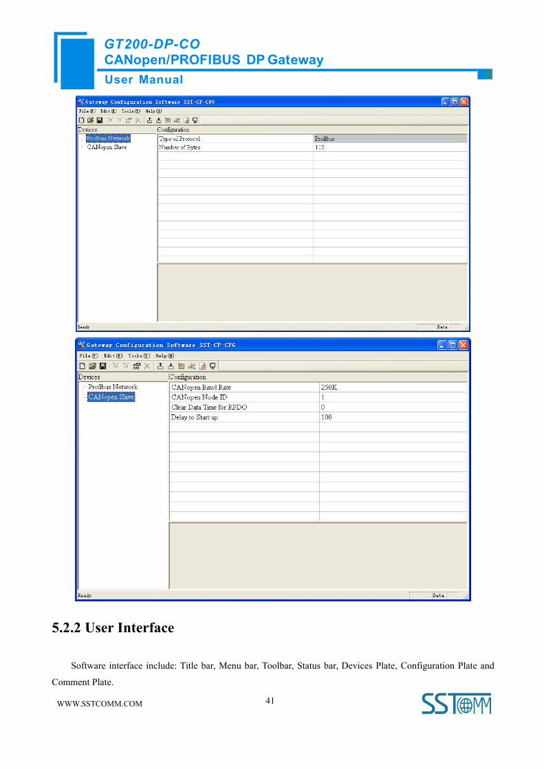
5.2.4.1 PROFIBUS ConfigurationLeft click Profibus network in Device Section, and you can see configuration section of fieldbus:
Items: Protocol type, Profibus input and output bytes
Protocol type: Profibus
Profibus input and output bytes: 112, 96, 48, 16 can be selected, and the default is 112.

User ManualCANopen/PROFIBUS DP GatewayGT200-DP-CO
WWW.SSTCOMM.COM 45
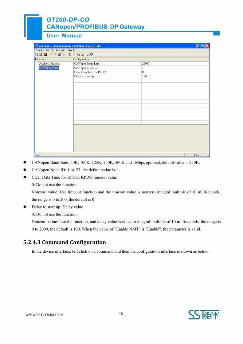
5.2.4.2 CANopen Network ConfigurationConfigurable parameters are shown as below:
CANopen Baud Rate, CANopen Node ID, Clear Data Time for RPDO and Delay to Start up.
CANopen configuration interface is shown as below:
User ManualCANopen/PROFIBUS DP GatewayGT200-DP-CO
WWW.SSTCOMM.COM 46
CANopen Baud Rate: 50K, 100K, 125K, 250K, 500K and 1Mbps optional, default value is 250K.
CANopen Node ID: 1 to127, the default value is 1
Clear Data Time for RPDO: RPDO timeout value
0: Do not use the function;
Nonzero value: Use timeout function and the timeout value is nonzero integral multiple of 10 milliseconds,
the range is 0 to 200, the default is 0
Delay to start up: Delay value
0: Do not use the function;
Nonzero value: Use the function, and delay value is nonzero integral multiple of 10 milliseconds, the range is
0 to 2000, the default is 100. When the value of "Enable NMT" is "Enable", the parameter is valid.
5.2.4.3 Command ConfigurationIn the device interface, left click on a command and then the configuration interface is shown as below:

User ManualCANopen/PROFIBUS DP GatewayGT200-DP-CO
WWW.SSTCOMM.COM 47
Slave Address: CANopen slave address, the range is 1 to127
COB-ID: The CAN ID (decimal) of CANopen PDO:
Default value of Transmit PDO command: 384(0x180) + node ID or 640(0x280) + node ID or 896 (0x380) +
node ID or 1152(0x480) + node ID
Default value of Receive PDO: 512(0x200) + node ID or 768(0x300) + node ID or 1024 (0x400) + node ID
or 1280 (0x500) + node ID
Mapping address: Memory address mapped in the gateway (Read only)
Mnemonic description: Users can input the description of project configuration items here; these are not
downloaded to gateway actually
5.2.4.4 Comment InterfaceComment interface displays the explanation of relevant configuration item. When the configuration item is
"COB-ID", the comment interface is shown as below:

User ManualCANopen/PROFIBUS DP GatewayGT200-DP-CO
WWW.SSTCOMM.COM 48
5.2.5 Hardware Communication
Communication menu is shown as follow:
5.2.5.1 COM ConfigurationThe software can scan usable serial port automatically, and show it in the port list. Finish all configurations,
click "OK" and save settings.
Remark: When you finish setting port, and other parameters are fixed value: 57600, 8, 0DD, 8, 1
5.2.5.2 UploadSelect "Upload", it will read configurations form the gateway, and the interface is shown as below:

User ManualCANopen/PROFIBUS DP GatewayGT200-DP-CO
WWW.SSTCOMM.COM 49
5.2.5.3 DownloadSelect "Download", it will download configurations to the gateway, and the interface is shown as below:
Remark1: Please confirm the port in "COM Config" is the port that you are using before downloading the
configurations;
Remark2: Please confirm the configurations are correct before downloading configurations (you can use "Export
EXCEL" function and it can help you check the configurations).

User ManualCANopen/PROFIBUS DP GatewayGT200-DP-CO
WWW.SSTCOMM.COM 50
5.2.6 Load and Save Configuration
5.2.6.1 Load Configuration ProjectSelect "Open", you can open the configuration project that you have saved.
5.2.6.2 Save Configuration ProjectSelect "Save" or "Save As", you can save the configuration project with chg as its extension.
5.2.7 Auto Mapping
The mapping address of every command in the gateway must be calculated by fixed formula, users can use
"Calculate Mapping Address" to calculate mapping address automatically.

User ManualCANopen/PROFIBUS DP GatewayGT200-DP-CO
WWW.SSTCOMM.COM 51
5.2.8 Export Excel File
Users can use the function to check the gateway configurations.
Select "Export EXCEL", you can save the configuration with .xls as its extension.
5.2.9 Monitor
When the first bit of DIP switch of GT200-DP-CO is set to "ON" status and the second bit is set to "OFF"
status, GT200-DP-CO is in the debug mode.
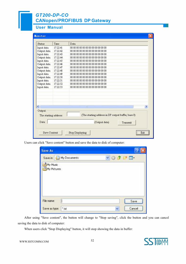
This function can monitor the data in the input buffer of gateway memory; the interface is shown as below:
There are no data in the buffer and the interface is shown as below:
User ManualCANopen/PROFIBUS DP GatewayGT200-DP-CO
WWW.SSTCOMM.COM 52
Users can click "Save content" button and save the data to disk of computer:
After using "Save content", the button will change to "Stop saving", click the button and you can cancel
saving the data to disk of computer:
When users click "Stop Displaying" button, it will stop showing the data in buffer:

User ManualCANopen/PROFIBUS DP GatewayGT200-DP-CO
WWW.SSTCOMM.COM 53
After using "Stop Displaying", the button will change to "Continue to display", click the button it will clear
the items before and show new contents again.
User ManualCANopen/PROFIBUS DP GatewayGT200-DP-CO
WWW.SSTCOMM.COM 54
6 Installation
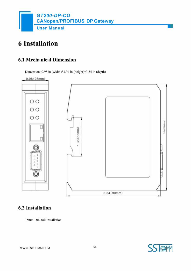
6.1 Mechanical Dimension
Dimension: 0.98 in (width)*3.94 in (height)*3.54 in (depth)
6.2 Installation
35mm DIN rail installation

User ManualCANopen/PROFIBUS DP GatewayGT200-DP-CO
WWW.SSTCOMM.COM 55

User ManualCANopen/PROFIBUS DP GatewayGT200-DP-CO
WWW.SSTCOMM.COM 56
7 Failures and Suggestions
Number Description Suggestions
1 PBF (PROFIBUS DP Failure) always read PROFIBUS DP connection fail
2 PBF (PROFIBUS DP Failure) read out PROFIBUS DP connection OK
3 CAN-STATUS read light on in run status
CAN BUS OFF or error counter beyond alert
value;
Check CAN baudrate of gateway, and the
baudrate must be the same with other nodes
of CAN network
4 CAN-STATUS read light blinking in run status
Need a terminal resistance1 on CAN network
or there is no connection between gateway
with CAN network
5CAN-STATUS green light on but CAN transmit and
receive data fail in run status
Need a terminal resistance1 on CAN network
or the node connected with gateway fail
6CAN-STATUS read light blinking in run status
occasionally
There is error frame form CAN network, will
not affect communication
7CAN-STATUS read light always blinking in run
status and no data in PROFIBUS DP
Check the baudrate of all the nodes on the
CAN network; If they are all the same, please
change a low baudrate and try again
8 ERR and RUN lights blinking fast Check PROFIBUS DP network
Note: Terminal resistance1
When communication distance is long or communication baudrate is high, users need a terminal resistance
(120Ω/2W) in both terminals of communication lines.

User ManualCANopen/PROFIBUS DP GatewayGT200-DP-CO
WWW.SSTCOMM.COM 57
Appendix: Using STEP7 Set PROFIBUS DP
The following show how to use STEP7 to configure GT200-DP-CO:
First of all, copy *. gsd file to the following path: Step7\S7data\gsd\
1. Open SIMATIC Manager ; Figure 1:
Figure 1
2. Click File->New, create a new project; Figure 2:
Figure 2
3. Insert->Station->SIMATIC 300 Station; Figure3:

User ManualCANopen/PROFIBUS DP GatewayGT200-DP-CO
WWW.SSTCOMM.COM 58
Figure 3
4. Open S7 PLC hardware configuration: SIMATIC 300(1)->Hardware, double-click; Figure 4:
Figure 4
User ManualCANopen/PROFIBUS DP GatewayGT200-DP-CO
WWW.SSTCOMM.COM 59
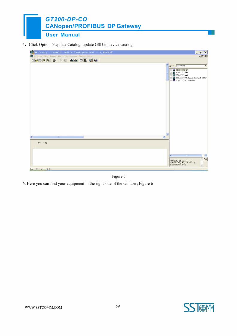
5.Click Option->Update Catalog, update GSD in device catalog.
Figure 5
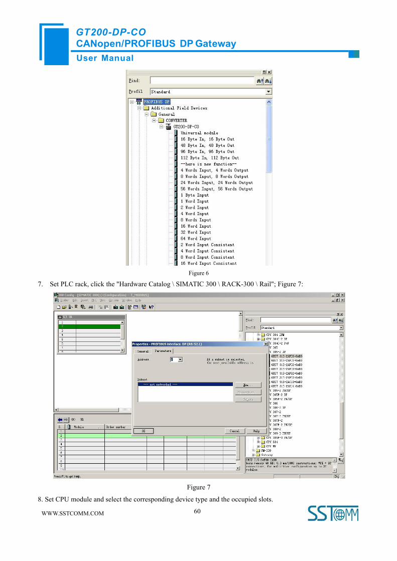
6. Here you can find your equipment in the right side of the window; Figure 6
User ManualCANopen/PROFIBUS DP GatewayGT200-DP-CO
WWW.SSTCOMM.COM 60
Figure 6
7. Set PLC rack, click the "Hardware Catalog \ SIMATIC 300 \ RACK-300 \ Rail"; Figure 7:
Figure 7
8. Set CPU module and select the corresponding device type and the occupied slots.

User ManualCANopen/PROFIBUS DP GatewayGT200-DP-CO
WWW.SSTCOMM.COM 61
9. Create PROFIBUS DP network and set up PROFIBUS DP: Click New and then Network settings, select DP;
select a baud rate such as 187.5Kbps, then "OK". Double-click it; Figure 8:
Figure 8
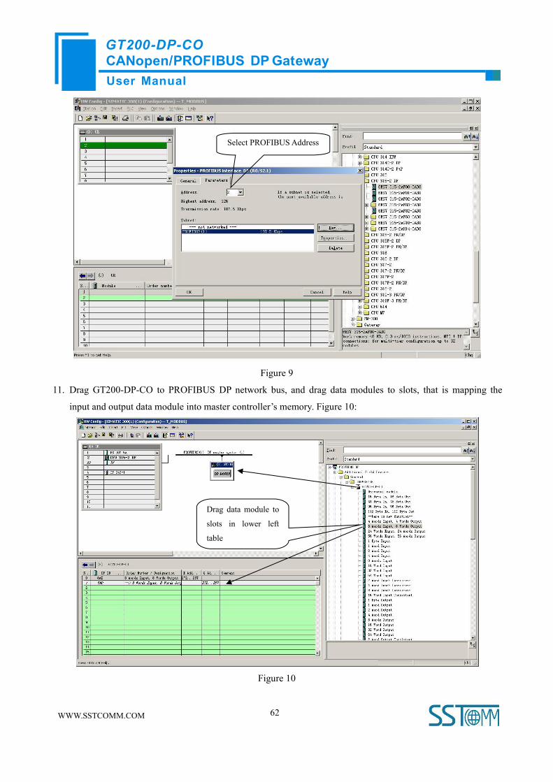
10. Select PROFIBUS Master station address, Figure 9:
User ManualCANopen/PROFIBUS DP GatewayGT200-DP-CO
WWW.SSTCOMM.COM 62
Figure 9
11. Drag GT200-DP-CO to PROFIBUS DP network bus, and drag data modules to slots, that is mapping the
input and output data module into master controller’s memory. Figure 10:
Figure 10
Drag data module to
slots in lower left
table
Select PROFIBUSAddress
User ManualCANopen/PROFIBUS DP GatewayGT200-DP-CO
WWW.SSTCOMM.COM 63
Operation is divided into two steps, the first step is dragging GT200-DP-CO to PROFIBUS DP network bus,
the mouse will change shape, and that is to say, it can be placed. The second step is dragging data module into
master controller’s memory.
Note 1: Users configure input and output bytes of GT200-DP-CO through configuration software SST-CP-CFG.
If users select 48, and then drag “48 Byte In, 48 Byte Out” to the slots. The default is “112 Byte In, 112 Byte Out”.
Note 2: The PROFIBUS DP slave address must be in line with the settings of module DIP switch!
12. Compile and download into PLC.


