Blue Manta AS Telephone: 01224 775576 Norsea Base, Building 104, 4098 Tananger, Norway BLUE MANTA AS WINDER CERTIFICATION PACKAGE BLUE MANTA SERIAL NUMBER: BM-WS-962 OFFICE ADDRESS: NORSEA BASE, BUILDING 104 4098 TANANGER NORWAY BLUE MANTA CONTACT: [email protected]
EC Declaration of Conformity In accordance with BS EN ISO/IEC 17050-1:2010
We: Blue Manta International 5 Kirkton Avenue Pitmedden Road Industrial Estate Dyce, Aberdeen, UK AB21 0BF Declare that: Equipment: 96” Winder System to suit Spooling Unit Classification: Group II Category 3 G IIB T4 Serial number: BM-WS-962 Is in accordance with the following Directives: 2014/34/EU Conforms to the Essential Health and Safety Requirements of the equipment in
Explosive Atmospheres (ATEX) Directive. 2009/127/EC Conforms to the Essential Safety Requirements of the Machinery Directive And has been designed and manufactured to the relevant parts of the following standards: EN 13463-1: 2009 Non – electrical equipment for use in potentially explosive atmospheres Part 1: Basic methods and requirements. EN 13463-5: 2011 Non-electrical equipment intended for use in potentially explosive atmospheres.
Protection by constructional safety 'c' EN 15198: 2007 Methodology for risk assessment of non-electrical equipment and components for
intended use in potentially explosive atmospheres.
And is built in accordance with the following additional standards: LR Rules for Lifting Appliances in a Marine Environment (L.A.M.E)
02-9600-SS/DOC/02
Page 2 of 2
The following ATEX certified parts are included in the assembly: Description Manufacturer Type/Model Type of protection Air motor Gast 6AM-NRV-22A N/A Gearbox SEW Eurodrive KA37/TAM56 N/A The following self assessed parts are included in the assembly Description Manufacturer Type/Model Ignition Risk Assessment Reference Bearings Scots Bearing CPT-FL212 Pneumatic components Norgren/Camozzi
Hydrasun
Special Conditions for safe use:
1. No unauthorised modifications to be carried out without the express permission of Blue Manta International as this may invalidate ATEX certification.
2. The unit must be effectively bonded to the structure of the offshore installation. 3. The accompanying instructions contain important information for the installation, operation and
maintenance of the equipment and must be adhered to.
I hereby declare that the equipment named above has been manufactured and tested and found to comply with the relevant sections of the above referenced directives and standards.
Z-015 DECLARATION OF CONFORMITY Supplier ID Type Description Blue Manta International Ltd
BM-WS-962 U99 Winder System to suit Back Tension Spooling Unit
This temporary/equipment is designed in accordance with NORSOK Z-015, without non-conformance , with non-conformance (see list below) , Date / name / company / position / signature:
17.12.15 / Ally Thomson / Blue Manta International Ltd / Base Manager /
This container/equipment is approved for location in Ex-zone: Zone 1 , Zone 2 , Non-hazardous area , Date / name / company / position / signature:
17.12.15 / Ally Thomson / Blue Manta International Ltd / Base Manager /
Use of this container/this equipment requires clearance in each case (see clause 4.5.1 pt e) This container/equipment is CE-marked, based on the following regulations (EEA directives, enforcement date for when the regulations apply without transition period):
Description of non-conformance Compensating measures/remarks
Restrictions or special requirements for use of container/equipment: No. Area of validity
(see NOTE) Description Name and date
(responsible person)
1. All No unauthorised modifications to be carried out without the express permission of Blue Manta International as this may invalidate ATEX certification
Ally Thomson 17.12.15
2. All The accompanying instructions contain important information for the installation, operation and maintenance of the equipment and must be adhered to.
Ally Thomson 17.12.15
Use of this equipment requires prior acceptance of responsible person in the company, see clause 4.8.3: Yes , No (If Yes, please list the conditions that require prior acceptance in the remarks column
NOTE - Can for example be installation, company or all
CERTIFICATE No: 02-9600-SS/DOC/Z015
Page 1 of 1
Z-015 Data Sheet for Temporary Equipment
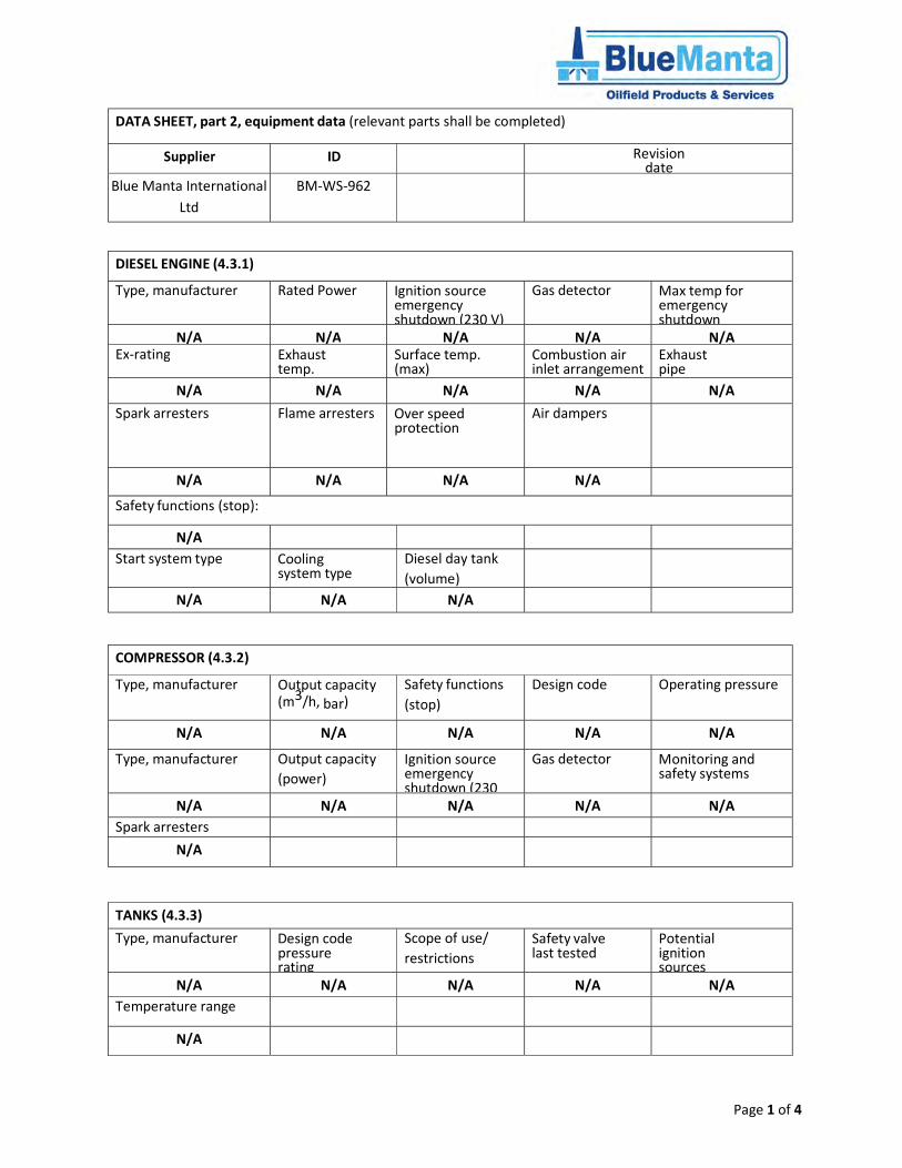
Z-015 Data Sheet for Equipment Part 1 (always to be completed)
Supplier ID No Type Description
Blue Manta International BM-WS-962 U99 Winder System to suit Back Tension Spooling
Unit
Outer Dimensions
(L x H x D)
Net Weight (kg)
Max Weight (kg) Approved for
location in Ex Zone Year of
Manufacture Latest Modification
2.8M x 1.88M x 1.15M
650kg
650kg Zone 2 2015 N/A
Manned when hooked up to Installation Connect suitable air supply (3/4” minimum hose diameter) via either Crows foot or MacDonald connection. Depending on the connection at the back of the air connection this may have to be changed to match the connection which is being used.
Pressurization (Pa) Shutdown in event of pressurization loss (time delayed, local alarm type)
N/A N/A N/A N/A N/A
DATA SHEET, part 4, Ex-data (list of Ex-approved equipment)
Supplier ID Revision date
Blue Manta International Ltd
BM-WS-961
Tag no. Description Approved zone
Certificate no.
6AM-NRV-22A Gast Air Motor Zone 2
KA37/TAM56 SEW Eurodrive Gearbox Zone 2
DATA SHEET, part 5 Working Environment Area Chart (WEAC)
Supplier ID Revision date
N/A
NORSOK standard Z-015 Rev. 4, September 2012
NORSOK standard Page 46 of 65
Annex C (Normative)
Checklist matrixes
See explanation of checklists in 4.1.1.
C
on
tro
l ite
ms
Checklist matrixes Containers Equip.
Type of container and equipment
Z-015 A
ccom
mod
atio
n co
ntai
ner
(A
) O
ffice
, cof
fee
bar,
lab,
RO
V, w
ell s
ervi
ce,
(B
) W
orks
hop
for
hot w
ork
(C
) W
orks
hop
for
cold
wor
k
(E)
Con
tain
er fo
r di
esel
eng
ine
(G
) S
tore
s fo
r fla
mm
able
mat
eria
ls
(I)
Sto
res
for
non-
flam
mab
le m
ater
ials
(J
) P
aint
ers’
wor
ksho
p
(L)
Ref
riger
atio
n an
d fr
eezi
ng c
onta
iner
s
(M)
Rad
io a
nd c
omm
unic
atio
ns ro
om
(N)
Toi
let c
onta
iner
(O
) E
lect
rical
equ
ipm
ent c
onta
iner
(P
) N
on-E
x-pr
oof e
quip
men
t con
tain
er
(Y)
Ex-
proo
f equ
ipm
ent c
onta
iner
(
Z)
Die
sel e
ngin
es
U01
A
ir co
mpr
esso
rs U
02
Tan
ks
U03
Hig
h pr
essu
re c
lean
ing
equi
pmen
t U
04
Ste
am g
ener
ator
U05
M
obile
cra
ne
U06
W
ell e
quip
., w
irelin
e, lo
ggin
g, c
oiltu
bing
U
07
Hab
itat f
or h
ot w
ork
Cla
ss A
U
08
Equ
ipm
ent f
or w
aste
han
dlin
g U
09
Pne
umat
ic/h
ydra
ulic
pum
p eq
uipm
ent e
tc.
U10
Non
-Ex-
proo
f equ
ipm
ent o
n sk
id
U98
E
x-pr
oof e
quip
men
t on
skid
U
99
Shall not be placed in hazardous area
X
X
X
X
X
X
1. MECHANICAL 1.1. Signs tagging/labelling 4.6 X X X X X X X X X X X X X X X X X X X X X X X X X X 1.2 Annual inspection (lifting equipment, cert.) 4.4.1 X X X X X X X X X X X X X X X X X X X X X X X X X X 1.3 Mech. cond. (lifting eyes/points, structure) 4.4.1 X X X X X X X X X X X X X X X X X X X X X X X X X X 1.4 Fire classification 4.4.1 X X X X X X X X X X X X 1.5 Air lock 4.4.1 X X X X 1.6 Self-closing doors 4.4.1 X X X X X X X X X X X X X X 1.7 Emergency exits 4.4.1 X X X X X X X X 1.8 Mechanical ventilation 4.4.7 X X X X X X X X X X X X 1.9 Noise measurement carried out (supplier) 4.4.8 X X X X X X X X X X 2. FIRE, GAS AND SAFETY 2.1 Gas detector in air inlet 4.4.3 X X X X X X X X X X X X X X X X X
NORSOK standard Z-015 Rev. 4, September 2012
NORSOK standard Page 47 of 65
Co
ntr
ol i
tem
s
Checklist matrixes Containers Equip.
Type of container and equipment
Z-015 A
ccom
mod
atio
n co
ntai
ner
(A
) O
ffice
, cof
fee
bar,
lab,
RO
V, w
ell s
ervi
ce,
(B
) W
orks
hop
for
hot w
ork
(C
) W
orks
hop
for
cold
wor
k
(E)
Con
tain
er fo
r di
esel
eng
ine
(G
) S
tore
s fo
r fla
mm
able
mat
eria
ls
(I)
Sto
res
for
non-
flam
mab
le m
ater
ials
(J
) P
aint
ers’
wor
ksho
p
(L)
Ref
riger
atio
n an
d fr
eezi
ng c
onta
iner
s
(M)
Rad
io a
nd c
omm
unic
atio
ns ro
om
(N)
Toi
let c
onta
iner
(O
) E
lect
rical
equ
ipm
ent c
onta
iner
(P
) N
on-E
x-pr
oof e
quip
men
t con
tain
er
(Y)
Ex-
proo
f equ
ipm
ent c
onta
iner
(
Z)
Die
sel e
ngin
es
U01
A
ir co
mpr
esso
rs U
02
Tan
ks
U03
Hig
h pr
essu
re c
lean
ing
equi
pmen
t U
04
Ste
am g
ener
ator
U05
M
obile
cra
ne
U06
W
ell e
quip
., w
irelin
e, lo
ggin
g, c
oiltu
bing
U
07
Hab
itat f
or h
ot w
ork
Cla
ss A
U
08
Equ
ipm
ent f
or w
aste
han
dlin
g U
09
Pne
umat
ic/h
ydra
ulic
pum
p eq
uipm
ent e
tc.
U10
Non
-Ex-
proo
f equ
ipm
ent o
n sk
id
U98
E
x-pr
oof e
quip
men
t on
skid
U
99
2.2 Fire/smoke detector 4.4.2 X X X X X X X X X X X X X X X X X 2.3 Fire hose 4.2.1 X 2.4 Portable fire extinguisher 4.4.2 X X X X X X X X X X X X X X X X X X 2.5 Fire damper 4.2.1 X 2.6 Alarm and shutdown if loss of pressurisation/ventilation 4.4.7 X X X X X X X X X X 2.7 Room fire extinguishing system 4.4.2 X X X X X X X 3. ELECTRICAL 3.1 Cables, glands, equipment etc. 4.4.6.1 X X X X X X X X X X X X X X X X X X X X X X X X X X 3.2 Insulation resistance - megger 4.8.1 X X X X X X X X X X X X X X X X X X X X X X X X X X 3.3 Earthing (NB bonding of structure) 4.4.6.3 X X X X X X X X X X X X X X X X X X X X X X X X X X 3.4 All external installation Ex-proof 4.4.6.2 X X X X X X X X X X X X X X X X X X X X X X X X X X 3.5 All internal installation Ex-proof 4.4.6.2 X X X X X X X X X X X X X X 3.6 Emergency lighting 4.4.6.2 X X X X X X X X X X X 4. HOOK-UP TO INSTALLATION 4.1 Power supply (voltage, freq., plugs) 4.7 X X X X X X X X X X X X X X X X X X X X X X X X X 4.2 Telephone with plug 4.7 X X X X X X 4.3 PA with plug 4.7 X X X X X X X X X X 4.4 Alarm signal to control room with plug 4.7 X X X X X X X X X X X X X X X X X X X X X X 4.5 Shutdown (ESD) from CCR (for battery system etc.) 4.4.3 4.4.6.4 X X X X X X X X X X 5. EQUIPMENT 5.1 Manual emergency stop 4.4.8 X X X X X X X X X X X 5.2 Manual shutdown of diesel supply 4.3.1 X X X X X X X 5.3 Drip trays 4.3.1 X X X X X X X 5.4 Shutoff damper in combustion air inlet 4.3.1 X X X X X X X
NORSOK standard Z-015 Rev. 4, September 2012
NORSOK standard Page 48 of 65
Co
ntr
ol i
tem
s
Checklist matrixes Containers Equip.
Type of container and equipment
Z-015 A
ccom
mod
atio
n co
ntai
ner
(A
) O
ffice
, cof
fee
bar,
lab,
RO
V, w
ell s
ervi
ce,
(B
) W
orks
hop
for
hot w
ork
(C
) W
orks
hop
for
cold
wor
k
(E)
Con
tain
er fo
r di
esel
eng
ine
(G
) S
tore
s fo
r fla
mm
able
mat
eria
ls
(I)
Sto
res
for
non-
flam
mab
le m
ater
ials
(J
) P
aint
ers’
wor
ksho
p
(L)
Ref
riger
atio
n an
d fr
eezi
ng c
onta
iner
s
(M)
Rad
io a
nd c
omm
unic
atio
ns ro
om
(N)
Toi
let c
onta
iner
(O
) E
lect
rical
equ
ipm
ent c
onta
iner
(P
) N
on-E
x-pr
oof e
quip
men
t con
tain
er
(Y)
Ex-
proo
f equ
ipm
ent c
onta
iner
(
Z)
Die
sel e
ngin
es
U01
A
ir co
mpr
esso
rs U
02
Tan
ks
U03
Hig
h pr
essu
re c
lean
ing
equi
pmen
t U
04
Ste
am g
ener
ator
U05
M
obile
cra
ne
U06
W
ell e
quip
., w
irelin
e, lo
ggin
g, c
oiltu
bing
U
07
Hab
itat f
or h
ot w
ork
Cla
ss A
U
08
Equ
ipm
ent f
or w
aste
han
dlin
g U
09
Pne
umat
ic/h
ydra
ulic
pum
p eq
uipm
ent e
tc.
U10
Non
-Ex-
proo
f equ
ipm
ent o
n sk
id
U98
E
x-pr
oof e
quip
men
t on
skid
U
99
5.5 Shutdown if loss of oil pressure 4.3.1 X X X X X X 5.6 Shutdown if high cooling water temperature 4.3.1 X X X X X X X 5.7 Shutdown if overspeed 4.3.1 X X X X X X 5.8 Diesel engine approved for zone 2 4.3.1 X X X X X X 5.9 Gas detector in combustion air inlet 4.3.1 X X X X X X X 5.10 Flame arrester in exhaust pipe 4.3.1 X X X X X X X 5.11 Spark arrester in exhaust pipe 4.3.1 X X X X X X X 5.12 Safety valve 4.3.5 X X X X X 5.13 Flame guard 4.3.5 X 5.14 Low water level alarm 4.3.5 X 5.15 Check of limit switches 4.3.6 X X 6. DOCUMENTATION 6.1 Lifting certificate 4.8 X X X X X X X X X X X X X X X X X X X X X X X X X X 6.2 Other technical doc. (drawings, data.) 4.8 X X X X X X X X X X X X X X X X X X X X X X X X X X 6.3 Certificate for equip. with special requ. 4.8 X X X X X X X X X X X X X X X X X X X X X X X X X X 6.4 Maintenance programme 4.8 X X X X X X X X X X X X X X X X X X X X X X X X X X 6.5 Maintenance journal 4.8 X X X X X X X X X X X X X X X X X X X X X X X X X X 6.6 User manual 4.8 X X X X X X X X X X X X X X X X X X X X X X X X X X
1. Before lifting the winder system out of the Blue
travel frame, please ensure you have removed the
bolts marked clearly on the frame. Please also keep
these as you will need them for securing the winder
system on to the spooler.
2. On the spooling unit, you will have to remove the two black pins shown (again
keep them as they will be needed for securing the winder system in place. The
large bar show will also need to be removed, please note this is heavy.
3. The winder system fits into the spooler like so:
Please note that both the bolts and pins must be in place to
secure the spooler
4. There is a small air hose connected to the winder system, this
needs to be connected to the spooler as shown:
5. Next you have to set up the control system. The
foot control has two connections. The crowsfoot
connection needs to be a direct air feed. The
Macdonald connection on the other side is
connected to the control panel.
6. You now have to connect the control panel. The red arrow below is the
Macdonald connection coming from the foot control. The Green arrows will be
connected to the winder and the blue arrows will be connected to the spooling
unit.
7.
8. The hose connections from the control panel
(Green arrows) are connected to the winder
system as shown. You may have to join air
hoses together to get the length you desire.
9. On the spooling unit you will need to remove the Green and Blue connections
and attach the fittings provided. Leave the red connection in as it acts as a
blank. Then connect the hose connections coming from the control panel
(blue arrows), again you may need to join air hoses together to get the length
you desire.
Page 1 of 2
SERVICE & MAINTENANCE PROCEDURE FOR GAST AIR
MOTOR
Although Gast have their own Operation and maintenance manual, Blue Manta have put
together the following instruction guide complete with photographs to assist in the service
of Gast air motors. These are only suggested guidelines and do not supersede Gast’s
operation and maintenance manual. Blue Manta cannot guarantee field-rebuilt product
performance.
DIS-ASSEMBLY PROCEDURE
1) Slacken grub screw on drive coupling and remove. (See figure 1) (The drive coupling
comes with the gear box and is not a part of the air motor redress kit) 2) Remove keyway. (See figure 2) 3) Remove dead end cap with Philips screwdriver. (See figure 3) 4) Remove 6 bolts using a 7/16 spanner from the dead-end plate. (See figure 4)
5) Remove rotary assembly and dead-end plate. Blue Manta recommend doing this
manually (see figure 5, 6, 7 & 8) but this can also be done using a hydraulic press:
- To remove manually, grip the motor between your ankles and use a plastic hammer or place a piece of wood or plastic to protect the end of the shaft and hammer the end until the unit comes loose. Safely remove the vanes, vane spring and push pins. (See figure 9) Be careful not to lose any of the components and place them in a safe and clean area.
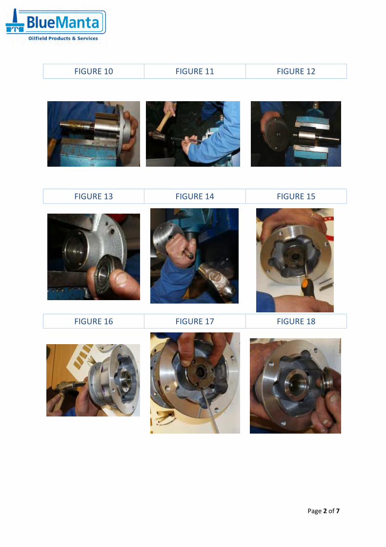
6) Separate the rotary assembly from the dead-end plate. - Place the rotary assembly in a bench vice (DO NOT GRIP). Open the vice far
enough so that the assembly lies on top of the vice. Hold the assembly with your arm and hammer at the same time until it comes loose. (See figure 10, 11 & 12)
7) Remove the bearing from the dead-end plate. - Place the dead-end plate in a bench vice (GRIP LIGHTLY). Use a hammer and
punch to remove the bearing. Work slowly around the edge of the bearing until the bearing comes loose. (See figure 13 & 14)
8) Remove the bearing from the body. - Remove three screws using a Philips screwdriver. Place the body in a vice and
use a punch to the remove the bearing from the other end - work around the bearing for it to slip out smoothly. (See figure 15, 16, 17, 18 & 19)
9) Clean and inspect all parts. - Clean the centre holes in the rotary assembly thoroughly using a fine needle
file as it is essential that the pins move backwards and forwards freely and smoothly. (See figure 21)
- Clean and emery the ends of the two shafts on the rotor assembly. (See figure 22)
- Emery all sealing surfaces both sides of the body and the dead-end plate using fine emery.
- Clean all other parts ready for re-assembly. (See figure 20) When assembling, ensure you lubricate the components thoroughly. DO NOT USE GREASE –preferred oil is Cengar Green Oil or a similar fine oil
Page 2 of 2
ASSEMBLY PROCEDURE
1) Fit 4 x push pins to rotary assembly and lubricate well. Ensure none of the push pins
are bent or damaged. (See figure 23) 2) Insert rotary assembly into motor body. (See figure 24)
3) Lubricate vanes and springs well. Insert first spring and vane. You must now install
the spring and vane opposite the one you have just installed. Proceed to fit springs
and vanes in this manner round the rotary assembly. (See figure 25, 26, 27, 28 & 29)
4) Fit gasket and dead-end plate and ensure dowels are aligned. Ensure rotary
assembly turns by hand after bolts are tightened. (See figure 30, 31, 32 & 33)
5) Fit dead-end bearing to dead end plate. Work slowly around the edge of the bearing
until the bearing is fully inserted. Ensure that the rotary assembly turns by hand.
(See figure 34, 355 & 33)
6) Fit bearing to motor body. Work slowly around the edge of the bearing until the
bearing is fully inserted. Rotate rotary assembly by hand. (See figure 36, 37 & 38)
7) If the rotary assembly does not turn or is tight to turn, you must tap the ends of
rotary assembly in either direction to centralise the assembly until it turns by hand.
The rotary assembly must not rub on the dead-end caps. The assembly should have
slight clearance between the dead-end caps. (See figure 39) 8) Lubricate bearings then fit dead end cap and cap seal on other end. (See figure 40,
41, 42, 43, 44 & 45)
9) Once assembled, turn the shaft on the air motor. You should be able to rotate the air
motor shaft by hand. If you are unable to turn the shaft the likelihood is that the
components are either not cleaned or lubricated properly or the shaft is rubbing on
the dead-end plate. The shaft must not rub on either end plate. (See figure 46)
CONNECTING THE AIR MOTOR TO THE GEAR BOX
1) Ensure that you install the plastic gear link. The gear coupling and plastic gear link
comes with the gear box and is not a part of the air motor redress kit. (See figure 47)
2) Install the keyway and gear coupling to the air motor and make up the grub screw
until it bottoms out. You should still be able to move the gear coupling. (See figure
48)
3) To set the gear coupling, connect the air motor to the gear box ensuring that the
drive coupling is far enough forward so that it meets the other gear coupling before
both parts come together. Push both parts together. Carefully remove the air motor
again. Lightly tap the gear coupling on the air motor back approx. 1mm using a
hammer and tighten the grub screw. It is important that both gear couplings are not
tight together. (See figures 49, 50 & 51)
4) Fit the air motor to the gear box. Move the air motor backwards and forwards. You
will see the shaft on the gear box move slightly. This will indicate that both gear links
are properly set. Make up the bolts. (See figure 52)
Page 1 of 7
SERVICE PROCEDURE OF GAST AIR MOTOR
DIS-ASSEMBLY PROCEDURE
FIGURE 1 FIGURE 2 FIGURE 3
FIGURE 4 FIGURE 5 FIGURE 6
FIGURE 7 FIGURE 8 FIGURE 9
Page 2 of 7
FIGURE 10 FIGURE 11 FIGURE 12
FIGURE 13 FIGURE 14 FIGURE 15
FIGURE 16 FIGURE 17 FIGURE 18
Page 3 of 7
FIGURE 19 FIGURE 20 FIGURE 21
FIGURE 22 FIGURE 23
Page 4 of 7
ASSEMBLY PROCEDURE
FIGURE 24 FIGURE 25 FIGURE 26
FIGURE 27 FIGURE 28 FIGURE 29
FIGURE 30 FIGURE 31 FIGURE 32
Page 5 of 7
FIGURE 33 FIGURE 34 FIGURE 35
FIGURE 36 FIGURE 37 FIGURE 38
FIGURE 39 FIGURE 40 FIGURE 41
Page 6 of 7
FIGURE 42 FIGURE 43 FIGURE 44
FIGURE 45 FIGURE 46
Page 7 of 7
FITTING AIR MOTOR TO GEAR BOX
FIGURE 47 FIGURE 48 FIGURE 49
FIGURE 50 FIGURE 51 FIGURE 52
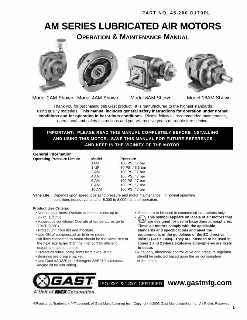
Product Use Criteria:• Normal conditions: Operate at temperatures up to
250ºF (121ºC).• Hazardous conditions: Operate at temperatures up to
104ºF (40ºC).• Protect unit from dirt and moisture.• Use ONLY compressed air to drive motor.• Air lines connected to motor should be the same size orthe next size larger than the inlet port for efficientoutput and speed control.
• Protect all surrounding items from exhaust air.• Bearings are grease packed.• Use Gast #AD220 or a detergent SAE#10 automotiveengine oil for lubricating.
• Motors are to be used in commercial installations only.• This symbol appears on labels of air motors that
are designed for use in hazardous atmospheres.These air motors comply with the applicable standards and specifications and meet the requirements of the guidelines of the EC directive 94/9EC (ATEX 100a). They are intended to be used in zones 1 and 2 where explosive atmospheres are likelyto occur.
• Air supply, directional control valve and pressure regulatorshould be selected based upon the air consumptionof the motor.
AM SERIES LUBRICATED AIR MOTORSOPERATION & MAINTENANCE MANUAL
Model 2AM Shown Model 4AM Shown
IMPORTANT: PLEASE READ THIS MANUAL COMPLETELY BEFORE INSTALLING
AND USING THIS MOTOR. SAVE THIS MANUAL FOR FUTURE REFERENCE
AND KEEP IN THE VICINITY OF THE MOTOR.
Thank you for purchasing this Gast product. It is manufactured to the highest standardsusing quality materials. This manual includes general safety instructions for operation under normalconditions and for operation in hazardous conditions. Please follow all recommended maintenance,
operational and safety instructions and you will receive years of trouble free service.
General informationOperating Pressure Limits: Model Pressure
1AM 100 PSI / 7 bar1 UP 80 PSI / 5.6 bar2 AM 100 PSI / 7 bar4 AM 100 PSI / 7 bar6 AM 100 PSI / 7 bar8 AM 100 PSI / 7 bar16 AM 100 PSI / 7 bar
Vane Life: Depends upon speed, operating pressure and motor maintenance. In normal operatingconditions inspect vanes after 5,000 to 8,000 hours of operation.
Read air motor label to check thatmotor has been designed for usein a hazardous application:• Hazardous zone• Hazardous category• Equipment group• Temperature class• Maximum surface temperatures
Gast Mfg. Corp.II 2GD c T5 *Benton Harbor, MI USATelephone: 269.926.6171
* Legend:II Equipment group II2 Equipment category 2G Gas atmospheresD Dust atmospheresc Constructional safetyT5 Max. surface temp. 212ºF/100ºC
Your safety and the safety of othersis extremely important.
We have provided many important safety messagesin this manual and on your product. Always readand obey all safety messages.
This is the safety alert symbol. This symbolalerts you to hazards that can kill or hurt you andothers. The safety alert symbol and the words“DANGER” and “WARNING” will precede all safetymessages. These words mean:
You will be killed or seriously injured if you don’tfollow instructions.
You can be killed or seriously injured if you don’tfollow instructions.
All safety messages will identify the hazard, tell youhow to reduce the chance of injury, and tell youwhat can happen if the safety instructions are notfollowed.
Correct installation is your responsibility. Make sureyou have the proper installation conditions.
INSTALLATION
WARNING
DANGER
WARNINGInjury Hazard
Install proper guards around output shaft asneeded.Air stream from product may contain solid or liquidmaterials that can result in eye or skin damage.Wear eye protection when installing this product.
Failure to follow these instructions can result inserious injury or property damage.
2
CODE SYMBOLSHazard. Possible consequences: death orsevere injuries.
Hazardous situation. Possibleconsequences: slight or mild injuries.
Dangerous situation. Possibleconsequences: damage to the drive or theenvironment.
Important instructions on protectionagainst explosion.
Application tips and usefulinformation.
Improper environment, installation and operationcan result in severe personal injury and/or damageto property.
Qualified personnel must perform all work toassemble, install, operate, maintain and repair airmotor.
Qualified personnel must follow:• These instructions and the warning and information
labels on the motor.• All other drive configuration documents, startup
instructions and circuit diagrams.• The system specific legal regulations and
requirements.• The current applicable national and regional
specifications regarding explosion protection,safety and accident prevention.
Complete the following checklist prior tostarting installation in a hazardous area. All
actions must be completed in accordance withATEX 100a.
Check the site environment for potentiallyexplosive oils, acids, gases, vapors or radiation
Check the ambient temperature of the site andthe ability to maintain proper ambienttemperature.Ambient range:Normal conditions: 34ºF/1ºC to 250ºF/121ºCHazardous conditions: 34ºF/1ºC to 104ºF/40ºC
Check the site to make sure that the air motorwill be adequately ventilated and that there isno external heat input (e.g. couplings). Thecooling air may not exceed 104ºF/40ºC.
Check that products to be driven by the airmotor meet ATEX approval.
Check that the air motor is not damaged.
Checklist for installation in hazardous areas:
Check the direction of the motor airflow. A singlerotation motor will operate properly only in one direction. Single rotation motors require a sound absorber to beconnected to the air port. Remove the plastic shippingplugs from the ports. Save plugs for future use duringshutdown.
3
Install a 5-micron filter in the air line before theconnection to the motor. Next install an air pressureregulator to control motor speed and torque.
Use the proper sized fasteners. For the most efficientoutput and control of speed, use air lines that are thesame size as the motor inlet port if the connection isless than 7 feet (2 meters). For longer connections, usethe next pipe size larger than the motor intake port.Connect lines to motor in the proper direction.
A reversible motor will work equally well in bothdirections. Connect a 4-way valve with piping to bothair ports of motor to make reversing possible. Connectthe sound absorber on the exhaust air port or valveconnection.
Do not add any thrust to the end or side of the shaftwhen making connections.
Lubricating the drive shaft will makeassembly easier. Use a puller for removal ofpulleys, couplings and pinions on the motor
shaft. Check that the tension on the belt pulleymatches the manufacturer’s specifications. Do notexceed the maximum radial and axial forces on theshaft. If the motor shaft is connected to the part tobe driven without a coupling, check that the radialoffset and axial force effect will not cause problems.
Do not use a hammer on the shaft orconnections.
Use only belts with < 10 9 electrical leakageresistance to prevent static electricalproblems.
AccessoriesA muffler is shipped with the air motor (except 16AM)but is not installed. Consult your GastDistributor/Representative for additional filterrecommendations. Install a moisture trap and 5 micronfilter in the air line ahead of motor.
Check all connections before starting motor. It isyour responsibility to operate this product atrecommended speeds, loads and room ambienttemperatures. Do not run the motor at high speedswith no load. This will result in excessive internalheat that may cause motor damage.
OPERATION
WARNINGInjury Hazard
Air stream from product may contain solid or liquidmaterial that can result in eye or skin damage.Do Not use combustible gases to drive this motor.Wear hearing protection. Sound level from motormay exceed 85db(A).
Failure to follow these instructions can result in eyeinjury or other serious injury.
Air consumption data at various speeds and pressuresare available from your Gast Distributor/Representativeor the factory.
The starting torque is less than the running torque. Thestarting torque will vary depending upon the position ofthe vanes when stopped in relation to the air intakeport.
MountingThis product can be installed in any orientation. Mountthe motor to a solid metal base plate that is mounted toa stable, rigid operating surface. Use shock mounts toreduce noise and vibration. Install a pressure regulatoror simple shut-off valve to control motor.
Fill the oil reservoir to the proper level with Gast#AD220 or SAE 10W high detergent or non-detergentmotor oil. For food processing applications, White Rex425 food grade motor oil is FDA approved. Adjustlubricator to feed 1 drop of oil for every 50 CFM of airwhile the unit is running, or 1 drop of oil per continuousminute of run time. Do Not overfeed oil or exhaust airmay become contaminated.
Clean the compressed air connection with low pressureair to remove any dirt from the line before connecting tothe ports.
Connection
An automatic air line lubricator should be installed in theair line as close as possible and no more than 18inches (1/2 meter) from the air motor. Install thelubricator level with or above the air motor so that the oilmist will blow directly into or fall down into the motor.
Use a pressure regulator and/or simple shut-off valve toregulate the motor’s speed and torque. This will providethe required power and will conserve air. Open the airsupply valve to the motor. Set the pressure or flow rateto the required speed or torque. Adjust the lubricator tofeed one drop of oil for every 50-75 CFM (1.5-2 M3 perminute) of air moving through motor. Check the oil leveldaily. The gear reducer does not need lubrication.
4
It is your responsibility to regularly inspect andmake necessary repairs to this product in order tomaintain proper operation.
Check intake and exhaust filters after first 500 hours ofoperation. Clean filters and determine how frequentlyfilters should be checked during future operation. Thisone procedure will help assure the motor’s performanceand service life.
FlushingFlushing this product to remove excessive dirt, foreignparticles, moisture or oil that occurs in the operatingenvironment will help to maintain proper vaneperformance. Flush the motor if it is operating slowly orinefficiently.
Use only Gast #AH255B Flushing Solvent. DO NOTuse kerosene or ANY other combustible solvents toflush this product.
1. Disconnect air line and muffler.2. Add flushing solvent directly into motor. If using
liquid solvent, pour several tablespoons directly into the intake port. If using Gast #AH255B, spraysolvent for 5-10 seconds into intake port.
3. Rotate the shaft by hand in both directions for a few minutes.
4. You must wear eye protection for this step. Cover exhaust with a cloth and reconnect the air line.
5. Restart the motor at a low pressure of approximately 10 PSI /0.7 bar until there is no trace of solvent in the exhaust air.
6. Listen for changes in the sound of the motor. If motor sounds smooth, you are finished. If motor does not sound like it is running smoothly,installing a service kit will be required(See “Service Kit Installation”).
Check that all external accessories such as reliefvalves or gauges are attached and are not damagedbefore operating product.
LubricationUse Gast #AD220 or a detergent SAE #10 automotiveengine oil for lubricating. Lubricating is necessary toprevent rust on all moving parts. Excessive moisture inair line may cause rust or ice to form in the mufflerwhen air expands as it passes through the motor.Install a moisture separator in the air line and an aftercooler between compressor and air receiver to helpprevent moisture problems.
Manual LubricationShut the air motor down and oil after every 8 hours ofoperation. Add 10-20 drops of oil to the air motor intakeport.
Automatic LubricationAdjust inline oiler to feed 1 drop of oil per minute forhigh speed or continuous duty usage. Do Not overfeedoil or exhaust air may become contaminated.
Cleaning sound absorber1. Remove the sound absorber.2. Clean the felt filter.3. You must wear eye protection for this step.
Lubricate motor with 3-4 drops of oil.4. Check the air compressor.5. Listen for changes in the sound of the motor. If
motor sounds smooth, you are finished. If motor does not sound like it running smoothly, installing a service kit will be required (See “Service Kit Installation”).
MAINTENANCE
WARNINGInjury Hazard
Disconnect air supply and vent all air lines.Wear eye protection when flushing this product.Air stream from product may contain solid or liquidmaterial that can result in eye or skin damage.Flush this product in a well ventilated area.Do Not use kerosene or other combustible solventsto flush this product.
Failure to follow these instructions can result in eyeinjury or other serious injury.
Operate the motor for approximately 2 hoursat the maximum desired load. Measure thesurface temperature of the motor on the
casting opposite the pipe ports. The maximumsurface temperature listed on the motor is fornormal environmental and installation conditions.For most air motors, the maximum surfacetemperature should not exceed 203ºF/95ºC. Do notcontinue to operate the motor if the measuredsurface temperature exceeds temperature listed onthe motor. If your measured temperature doesexceed listed value, consult with your GastDistributor/Representative for a recommendation.
ShutdownIt is your responsibility to follow proper shutdownprocedures to prevent product damage.1. Turn off air intake supply.2. Disconnect air supply and vent all air lines.3. Disconnect air lines.4. Remove air motor from connecting machinery.5. Remove the muffler.6. Wear eye protection. Keep away
from air stream. Use clean, dry air to remove condensation from the inlet port of the motor.
7. Lubricate motor with a small amount of oil into the intake port. Rotate shaft by hand several times to distribute oil.
8. Plug or cap each port.9. Coat output shaft with oil or grease.10. Store motor in a dry environment.
5
Gast will NOT guarantee field-rebuilt productperformance. For performance guarantee, theproduct must be returned to a Gast AuthorizedService Facility.
SERVICE KIT INSTALLATION
Service Kit contents vary. Most contain vanes, end capgasket, body gasket, bearings and a muffler element orfelt.
Major and Minor RebuildsTool kits which include a more in-depth rebuildmanual are available through your GastDistributor/Representative. These kits include thetools required to remove and reassemble end plates,bearings and shaft seals, and to set the proper endclearance. The rebuild manual also includes step bystep instructions, including illustrations, to help achievea successful rebuild. Gast Manufacturing, Inc. highlyrecommends using the air motor rebuild manual andtool kit when attempting a minor or major rebuild to yourGast air motor.
6. Remove vanes and ejection mechanism if reversible. (Ejection mechanisms may consist of vane springs, pins, caps or cam rings.)
7. Remove shaft seal and bearings from drive end plate andbearing from dead end plate. (Use factory issued tool.)
8. Do Not remove drive end plate bolts or drive end plate.9. Clean parts. Check for scoring on the end plates
and rotor assembly. If scoring exists, send unit to a GastAuthorized Service Facility.
10. For reversible models only :1AM and 1UP models - place a new cam ring betweenthe rotor and the drive end plate.2AM and 4AM models - place springs and caps in rotor.6AM, 8AM and 16AM models - install push pins.
11. Place the drive shaft of the rotor assembly through thedrive end plate. Press the drive bearing onto the driveshaft using a factory supplied bearing pusher.
12. Using the bearing taper from the Tool Kit, lightly tap on inner race of the drive end bearing to snugup rotor to drive end plate.
13. Install new vanes as required by model:All single rotation units - the angle cuts on thevane face to center of the rotor.Reversible units 2AM and 4AM - the notch onvane faces to center of the rotor.6AM, 8AM and 16AM models - install the vanespring lip into the notch at one end of the vaneand place in rotor vane slot with spring facingpushpin.
14. Place the proper end plate gasket on the body ofdead end. If the original is damaged, replacewith a new one supplied in the service kit.If your air motor uses O-rings, place the newO-rings in the body groove. Some models do no
t use end plate gaskets or O-rings.15. Place the dead end plate on the body.16. Install the dead end bearing and press into place
with bearing pusher tool from tool kit.17. Install the dowel pins.18. Fully tighten the remaining bolts to 75-100 in-lbs.19. Set end clearance as required by model:
1AM-4AM and NL22-NL52 models - use thebearing taper from the Tool Kit and lightly tap onthe inner race of the dead end bearing to free up and center the rotor in the body.6AM-8AM models - lightly strike the drive endshaft with a soft hammer to push the rotor away from the drive end plate. The rotor must NOT rubon either end plate.
20. Apply a small amount of grease to bearing sealand install the drive end bearing seal by pressingflush with bearing pushing tool from Tool Kit.
21. Reattach end cap.22. If the air motor is lubricated , apply a few drops
of Gast #AD220 lubricant into ports and rotateshaft by hand for a few rotations.
Minor Rebuild:1. Remove the end cap.2. Remove dead end plate bolts.3. Remove dead end plate. (Use factory issued tool, do not use screwdriver to remove the end plate.4. Remove the dowel pins from the body and push
back into end plate until flush or just below the machined surface of the end plate.
5. Remove vanes.6. Clean parts. Check for scoring on the end plate
and rotor assembly. If scoring exists, send unit to a Gast authorized service facility.
7. Lubricated models only: Lightly oil and reinstall vanes.
8. Place the proper end plate gasket on the end plate. If the original is damaged, replace with a new one supplied in the Service Kit.
9. Place the dead end plate on the body.10. Press the bearing onto the shaft using a factory
supplied bearing pusher.11. Tap dowel pins into body and install end plate
bolts. Tighten bolts to 75-100 in-lbs.12. Set end clearance as required by model:
1AM-4AM and NL22-NL52 models - use the bearing taper from kit to lightly tap oninner race of the dead end bearing to free up andcenter the rotor in the body.6AM-8AM models - lightly strike the drive end shaft with a soft hammer to push the rotor away from the drive end plate. The rotor must NOT rub on either end plate.
13. Reattach end cap.14. If the air motor is lubricated , apply a few drops
of Gast #AD220 lubricant into ports. Rotate shaft by hand for a few rotations.
Major Rebuild:1. Remove the end cap.2. Remove dead end plate bolts.3. Remove dead end plate. (Use factory issued tool,
do not use screwdriver to remove the end plate.)4. Remove the dowel pins from the body and push
back into end plate until flush or just below the machined surface of the dead end plate.
5. Remove rotor using an arbor press.
6
Model Total End Clearance Top ClearanceIn./mm In./mm
* Models with the last three digits greater than 500(i.e. 2AM XXX-501)
Clearances
Disposal (Please note current regulations)Parts of the air motor or air powered gear motor,shafts, cast iron or aluminum castings, gearwheels as well as rolling contact bearings may berecycled as scrap metal.
*** Item not shown.∆ Denotes parts included in the Service Kit.
∆∆ Parts listed are for stock models manufactured prior to 1998. For specific OEM models, please consult the factory. When corresponding about or ordering parts, please give complete model and serial numbers.Exploded views are shown for reference only. Units may vary depending upon specific model.
EXPLODED PRODUCT VIEW, PARTS & ORDERING INFORMATION 1AM/1UP SERIES
8
*** Item not shown.** #AL484 (5A) O-ring replaces shim on some models.
∆ Denotes parts included in the Service Kit.For specific OEM models, please consult the factory.
When corresponding about or ordering parts, please give complete model and serial numbers.Exploded views are shown for reference only. Units may vary depending upon specific model.
EXPLODED PRODUCT VIEW, PARTS & ORDERING INFORMATION 2AM SERIES
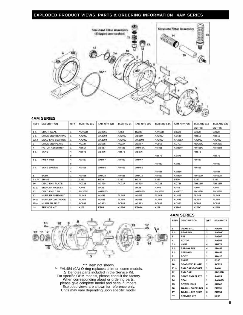
EXPLODED PRODUCT VIEWS, PARTS & ORDERING INFORMATION 4AM SERIES
4AM SERIES
REF# DESCRIPTION QTY 4AM-RV-75
1 GEAR STD. 1 AA294
2 ∆ BEARING 2 AA299J
3 PIN 1 AA297
4 ROTOR 1 AA293
5 ∆ VANE 4 AB876
6 ∆ SPRING PIN 4 AM467
7 ∆ SPRINGS 2 AM466
8 BODY 1 AM410
9 ∆ SHIMS 2 B330
10 DEAD END PLATE 1 AC728
11 ∆ END CAP GASKET 1 AA46
12 END CAP 1 AM307D
13 DRIVE END PLATE 1 AA424
14 SEAL 1 AA466B
15 DOWEL PINS 4 AB162
16 1/4-28 x .50 PFHMS 6 BB631
17 1/4-28 x .625 SHCS 6 BB634
*** SERVICE KIT 1 K205
4AM SERIES
*** Item not shown.** #AL484 (9A) O-ring replaces shim on some models.
∆ Denotes parts included in the Service Kit.For specific OEM models, please consult the factory.
When corresponding about or ordering parts,please give complete model and serial numbers.
Exploded views are shown for reference only.Units may vary depending upon specific model.
10
EXPLODED PRODUCT VIEW, PARTS & ORDERING INFORMATION 6AM SERIES
*** Item not shown.∆ Denotes parts included in the Service Kit.
For specific OEM models, please consult the factory. When corresponding about or ordering parts, please give complete model and serial numbers.Exploded views are shown for reference only. Units may vary depending upon specific model.
*** Item not shown.∆ Denotes parts included in the Service Kit.
For specific OEM models, please consult the factory. When corresponding about or ordering parts, please give complete model and serial numbers.Exploded views are shown for reference only. Units may vary depending upon specific model.
12
EXPLODED PRODUCT VIEW, PARTS & ORDERING INFORMATION 16AM SERIES
6 ∆ DRIVE END BEARING 1 AB777A AB777A AB777A AB777A
7 SPACER AD786 AD786 AD786 AD786
8 DRIVE END PLATE 1 AD771A AD820A AC323
9 DOWEL PIN 4 AB162A AB162A AB162A AB162A
10 ∆ SPACER GASKET 2 AD788 AD788 AD788
11 BODY 1 AD770 AD819 AD819 AD770B
12 DRIVE KEY 1 AC628 AC628 AB136D AC628
13 ROTOR ASSEMBLY 1 AD775 AD794 AE807
14 ∆ PUSH PIN 3 AD822 AD822
15 ∆ VANE SPRING 6 AD796A AD796A
16 ∆ VANE 6 AD781 AD795 AD795 AD781
17 DEAD END PLATE 1 AD773A AD821A AD821A
18 DEAD END BEARING 1 AD802 AD802 AD802 AD802
19 END CAP GASKET 1 AG406 AG406 AG406 AG406
20 DEAD END CAP 1 AG405 AG405 AD405 AG405
*** SERVICE KIT 1 K212 K213 K213 K212
16AM SERIES
*** Item not shown.∆ Denotes parts included in the Service Kit.
For specific OEM models, please consult the factory. When corresponding about or ordering parts, please give complete model and serial numbers.Exploded views are shown for reference only. Units may vary depending upon specific model.
13
General Information:The product nameplate specifies all information requiredwhen ordering parts or requests for information. Thetype of lubricant required for unit is also specified on thenameplate.
STANDARD & WORM GEAR REDUCERS - OPERATING AND MAINTENANCE INSTRUCTIONS
Product Use Criteria:• All worm gear reducers require that the air motor be
mounted so that the inlet and exhaust ports are at a 90º angle to the centerline of the reducer output shaft.
• Gear reducers are NOT self-locking. If a brake isrequired for safety, as in the case of air pressure failure,etc., contact your Gast Distributor/Representative.
• Worm gear reducers are shipped with a plug in the toppipe plug. The plug must be removed and the breatherplug installed for proper operation.
• Operating an air motor without venting will createinternal pressure build-up which can damage theinternal parts of the gear reducer.
• Check the oil level in units which have been stored ornot operated for a period of time.
• Gear motors require proper lubrication. Insufficient oillevel can cause loss of performance, damage or failureof the gear reducer.
Model GR11 GR20 GR25
Speed Range 33.3 to 400 RPM 30 to 300 RPM 20 to 200 RPM(Reducer Output Shaft)
Gear Reduction 15:1 10:1 15:1
Maximum Allowable 100 lbs/45,4 kg 200 lbs/90,8 kg @300 250 lbs/113,5 kg at 200End Thrust With RPM to 800 lbs/363,2 kg RPM to 800 lbs/363,2 kgZero Overhung Load. at 30 RPM at 20 RPM(Reducer Output Shaft)
Maximum Allowable 100 lbs/45,4 kg at 333 200 lbs/90,8 kg at 300 200 lbs/90,8 kg at 200Overhung Load With RPM to 200 lbs/90,8 kg RPM to 600 lbs/272,4 kg RPM to 600 lbs/272,4 kgZero End Thrust. at 33.3 RPM at 30 RPM at 20 RPM(Reducer Output Shaft)
Lubrication Use a 300 ssu at 100˚F/38˚C turbine quality lubricant – Gast #AG292A, GulfHarmony 53, Shell Tellus 33, Socony DTE heavy medium or Humble Nuto 53.For horizontal operation, remove both plugs and add oil to top hole untilother hole overflows.For vertical operation, fill to overflow point of upper most hole.
Gear Reducer Specifications
Worm Gear Reducer Series A-FGear Reducer SpecificationsAll output shafts are in the standard location.
Model Air Motor Ratio
AG803 4AM 20:1
AG805 4AM 40:1
AG807 4AM 60:1
AG809 6AM 10:1
AG811 6AM 20:1
AG816 8AM 20:1
Change output shaft direction1. Remove drain plug and drain oil from unit.2. Remove end cover and seal cage cap screws.
While supporting output shaft, remove end cover and shims from unit. Keep shims with cover.
3. Remove output shaft and seal cage together from extension side. Keep shims with seal cage.
4. Insert seal cage, shims and sub-assembly into housing from the side opposite from which they were removed.
5. Insert seal cage cap screws and tighten with light pressure.
6. Assemble end cover with shims. Insert end cover cap screws and tighten with light pressure.
7. Turn high speed shaft in both directions to check that gear train is running freely.
8. Cross-tighten seal cage and end cover cap screws.Service, Parts or Repair
For service, parts or repair of the worm gear reducer,contact the manufacturer listed on the nameplate.
14
REF# DESCRIPTION QTY PART NO.
1 GEAR HOUSING 1 AC737
2 GEAR HOUSING COVER 1 AC736
3 GEAR SHAFT 1 AC739
4 CLUSTER GEAR 1 AC738
5 SNAP-RING 1 AE189
6 BEARING 1 AE196A
7 SEAL 1 AA517A
8 BEARING 1 AA498
9 BEARING 1 AE195
10 O-RING 1 AD823
11 BEARING 1 AE197
12 SEAL 1 AA623D
13 SCREWS 4 BB542
14 PIPE PLUG 2 BA500
15 SET SCREW 2 BB626
*** DOWEL PIN 2 AE882
GR11 SERIES
EXPLODED PRODUCT VIEWS, PARTS & ORDERING INFORMATION
REF# DESCRIPTION QTY PART NO.
1 GEAR SHAFT - OUTPUT 1 AE848
2 RETAINING RING 1 AE853
3 BEARING 1 AE858
4 OIL SEAL 1 AE852
5 BEARING 1 AE857
6 SCREW 6 BB652
*** DOWEL PIN 2 AF482
8 MAGNETIC DRAIN PLUG 2 AH471
9 GEAR - INPUT 1 AA294
10 OIL SEAL 1 AE851
11 HOUSING COVER 1 AE849
12 O-RING 1 AE854
13 GEAR HOUSING 1 AE850
14 GEAR SHAFT 1 AE845
15 GEAR - INTERMEDIATE 1 AE846
16 KEY 1 AE855
17 BEARING 2 AG549
18 KEY 1 AC628
GR20 SERIES
REF# DESCRIPTION QTY PART NO.
1 BEARING 2 AG549
2 GEAR SHAFT 1 AE845
3 GEAR INTERMEDIATE 1 AE846
4 GEAR HOUSING 1 AE850
5 SEAL 1 AE851
6 SEAL 1 AE852
7 RETAINING RING 1 AE853
8 O-RING 1 AE854
9 KEY 1 AE855
10 BEARING 1 AE857
11 BEARING 1 AE858
*** DOWEL PIN 2 AF482
13 HOUSING COVER 1 AH278
14 GEAR SHAFT - OUTPUT 1 AH279
15 MAGNETIC DRAIN PLUG 2 AH471
16 SCREWS 6 BB652
17 KEY 1 AC628
GR25 SERIES
*** Item not shown.
*** Item not shown.
15
MAINTENANCE RECORD
DATE PROCEDURE PERFORMED
Gast finished products, when properly installed and operated under normal conditions of use, are warranted by Gast tobe free from defects in material and workmanship for a period of twelve (12) months from the date of purchase fromGast or an authorized Gast Representative or Distributor. In order to obtain performance under this warranty, the buyermust promptly (in no event later than thirty (30) days after discovery of the defect) give written notice of the defect toGast Manufacturing Incorporated, PO Box 97, Benton Harbor Michigan USA 49023-0097 or an authorized ServiceCenter (unless specifically agreed upon in writing signed by both parties or specified in writing as part of a Gast OEMQuotation). Buyer is responsible for freight charges both to and from Gast in all cases.
This warranty does not apply to electric motors, electrical controls, and gasoline engines not supplied by Gast. Gast’swarranties also do not extend to any goods or parts which have been subjected to misuse, lack of maintenance,neglect, damage by accident or transit damage.
THIS EXPRESS WARRANTY EXCLUDES ALL OTHER WARRANTIES OR REPRESENTATIONS EXPRESSED ORIMPLIED BY ANY LITERATURE, DATA, OR PERSON. GAST’S MAXIMUM LIABILITY UNDER THIS EXCLUSIVEREMEDY SHALL NEVER EXCEED THE COST OF THE SUBJECT PRODUCT AND GAST RESERVES THE RIGHT,AT ITS SOLE DISCRETION, TO REFUND THE PURCHASE PRICE IN LIEU OF REPAIR OR REPLACEMENT.
GAST WILL NOT BE RESPONSIBLE OR LIABLE FOR INDIRECT OR CONSEQUENTIAL DAMAGES OF ANY KIND,however arising, including but not limited to those for use of any products, loss of time, inconvenience, lost profit, laborcharges, or other incidental or consequential damages with respect to persons, business, or property, whether as aresult of breach of warranty, negligence or otherwise. Notwithstanding any other provision of this warranty, BUYER’SREMEDY AGAINST GAST FOR GOODS SUPPLIED OR FOR NON-DELIVERED GOODS OR FAILURE TO FURNISHGOODS, WHETHER OR NOT BASED ON NEGLIGENCE, STRICT LIABILITY OR BREACH OF EXPRESS ORIMPLIED WARRANTY IS LIMITED SOLELY, AT GAST’S OPTION, TO REPLACEMENT OF OR CURE OF SUCHNONCONFORMING OR NON-DELIVERED GOODS OR RETURN OF THE PURCHASE PRICE FOR SUCH GOODSAND IN NO EVENT SHALL EXCEED THE PRICE OR CHARGE FOR SUCH GOODS. GAST EXPRESSLY DISCLAIMSANY WARRANTY OF MERCHANTABILITY OR FITNESS FOR A PARTICULAR USE OR PURPOSE WITH RESPECTTO THE GOODS SOLD. THERE ARE NO WARRANTIES WHICH EXTEND BEYOND THE DESCRIPTIONS SETFORTH IN THIS WARRANTY, notwithstanding any knowledge of Gast regarding the use or uses intended to be madeof goods, proposed changes or additions to goods, or any assistance or suggestions that may have been made by Gastpersonnel.
Unauthorized extensions of warranties by the customer shall remain the customer’s responsibility.
CUSTOMER IS RESPONSIBLE FOR DETERMINING THE SUITABILITY OF GAST PRODUCTS FOR CUSTOMER’SUSE OR RESALE, OR FOR INCORPORATING THEM INTO OBJECTS OR APPLICATIONS WHICH CUSTOMERDESIGNS, ASSEMBLES, CONSTRUCTS OR MANUFACTURES.
This warranty can be modified only by authorized Gast personnel by signing a specific, written description of anymodifications.
WARRANTY
16
TROUBLESHOOTING CHART
Problem
Low Low Won’t Run Runs Hot Runs Well Reason & RemedyTorque Speed Then Slows For Problem.
Down
• • • Dirt or foreign material present.Inspect and clean.
• • • Internal rust. Inspect and clean.
• • • • • Vanes misaligned. Realign vanes.
• • Low air pressure. Increase pressure.
• Air line too small. Install larger line(s).
• • Restricted exhaust. Inspect and repair.
• • • • Motor is jammed. Disassemble and repair.
• • Air source inadequate. Inspect and repair.
• • Air source too far from motor.Reconfigure setup.
www.gastmfg.comISO 9001 & 14001 CERTIFIED
PART NO. 45-200 D170PL
We have Gast Authorized Repair Facilities throughout the world. For the mostup-to-date listing, contact one of our sales offices below:
World Headquarters
P.O. Box 972550 Meadowbrook Rd.Benton Harbor, MI 49023-0097Ph: 269/926-6171FAX: 269/925-8288www.gastmfg.com
Eastern Sales Office
505 Washington Ave.Carlstadt, NJ 07072Ph: 201/933-8484FAX: 201/933-5545www.gastmfg.com
European Sales & ServiceHeadquarters
Beech House Knaves BeechBusiness CentreLoudwater, High WycombeBucks, England HP10 9SDTel: +44 1628 551500Fax: +44 1628 551590www.gastltd.com
Gast Hong Kong
Unit 12, 21/F, Block BNew Trade Plaza6, On Ping Street, ShatinN. T. Hong KongPh: (852) 2690 1008Fax: (852) 2690 1012www.gasthk.com
SAFETY DATA SHEET
Pneumatic tool oil Luna AIRTOIL 15 155300106, 0205, 0304
Last changed: 21/10/2014 Replaces date: 09/05/2012 Internal No. 155300106
SECTION 1: Identification of the substance/mixture and of the company/undertaking
1.1. Product identifier
Trade name Pneumatic tool oil Luna AIRTOIL 15 155300106, 0205, 0304
1.2. Relevant identified uses of the substance or mixture and uses advised against RECOMMENDED USES: Lubricant
1.3. Details of the supplier of the safety data sheet
SECTION 2: Hazards identification
2.1. Classification of the substance or mix ture
DPD Classification: Xn; R65
CLP Classification: Asp. Tox. 1;H304
Most serious harmful effects:: May be fatal if swallowed and enters airways.
2.2. Label elements
Signal word: None
EC-Label: No
COMPOSITION
VITOLJA, HÖGRAFFINERAD MINERALOLJA (100 %)
H-phrases
H304 May be fatal if swallowed and enters airways.
SAFETY DATA SHEET
Pneumatic tool oil Luna AIRTOIL 15 155300106, 0205, 0304
Last changed: 21/10/2014 Replaces date: 09/05/2012 Internal No. 155300106
SUPPLEMENTAL HAZARD INFORMATION (EU)
Risk of aspiration with chemical pneumonia.
2.3. Other hazards
OTHER HAZARDS Not known
SECTION 3: Composition/information on ingredients
3.2. Mixtures Ingredient name Reg.
no.
EC No. CAS No. Conc.
(wt%)
DPD-Classification CLP-classification
VITOLJA, HÖGRAFFINERAD
MINERALOLJA
232-455-8 8042-47-5 100 % R65 Asp. Tox. 1 H304
Full text of R-, H- and EUH-phrases: see section 16.
The EUH hazard statements mentioned in CLP-classification are only label elements.
SECTION 4: First aid measures
4.1. Description of first aid measures
INHALATION Provide rest, warmth and fresh air. Rinse nose, mouth and throat with water. Get medical attention if any discomfort
continues.
INGESTION
DO NOT INDUCE VOMITING!Contact physician.
SKIN Wash skin with soap and water. Remove contaminated clothing. Get medical attention if any discomfort continues.
Immediate hospital care if the product has been forced through the skin at high pressure.
EYES
Rinse with water. Get medical attention if any discomfort continues.
4.2. Most important symptoms and effects, both acute and delayed
MOST IMPORTANT SYMPTOMS AND EFFECTS, BOTH ACUTE AND DELAYED Aspiration during vomiting or ingestion may cause chemical pneumonia. Pulmonary oedema may appear several hours/days
after exposure.
4.3. Indication of any immediate medical attention and special treatment needed
INDICATION OF ANY IMMEDIATE MEDICAL ATTENTION AND SPECIAL TREATMENT NEEDED Treat symptomatically.
SAFETY DATA SHEET
Pneumatic tool oil Luna AIRTOIL 15 155300106, 0205, 0304
Last changed: 21/10/2014 Replaces date: 09/05/2012 Internal No. 155300106
SECTION 5: Firefighting measures
5.1. Extinguishing media
SUITABLE EXTINGUISHING MEDIA: Fire may be extinguished using powder, foam or carbon dioxide (CO2).
UNSUITABLE EXTINGUISHING MEDIA
Do not use water.
5.2. Special hazards arising from the substance or mixture
SPECIAL HAZARDS Evolves combustible gases if heated.In the event of a fire, irritating smoke is formed. Carbon monoxide may be formed in the
event of incomplete combustion.
5.3. Advice for firefighters
ADVICE FOR FIREFIGHTERS
Wear suitable respiratory protection.
OTHER INFORMATION Only trained personnel may undertake fire fighting in enclosed spaces. Containers close to fire should be removed
immediately or cooled with water.
SECTION 6: Accidental release measures
6.1. Personal precautions, protective equipment and emergency procedures
PERSONAL PRECAUTIONS
Bank in the discharge. Use personal protective equipment.
6.2. Environmental precautions
ENVIRONMENTAL PRECAUTIONS
Prevent discharges into the sewage system, watercourses or lakes.
6.3. Methods and material for containment and cleaning up
METHODS AND MATERIAL Prevent dispersion through damming with sand, earth or other suitable material. Wipe away or soak up with an absorbent
material. Immediately inform the authorities if the emission reaches the sewage system and watercourses. Inform the
emergency service in the event of major spillage. Treat as dangerous waste. In the event of spillage into water: Enclose by
booms and pump out as much as possible, collect minor quantities, e.g. in bark, and remove immediately.
SAFETY DATA SHEET
Pneumatic tool oil Luna AIRTOIL 15 155300106, 0205, 0304
Last changed: 21/10/2014 Replaces date: 09/05/2012 Internal No. 155300106
7.2. Conditions for safe storage, including any incompatibilities
7.3. Specific end use(s)
7.3. SPECIFIC END USE(S) Remains and waste must be treated as dangerous waste.
SECTION 8: Exposure controls/personal protection
8.1. Control parameters
LEGAL BASIS
AFS 2011:18
Occupational exposure limits
Ingredient name CAS No. Range ppm mg/m3 Year Remarks
VITOLJA, HÖGRAFFINERAD MINERALOLJA 8042-47-5 15 min. 3
VITOLJA, HÖGRAFFINERAD MINERALOLJA 8042-47-5 8 h 1
R=Toxic for reproduction, H=Skin absorption, K=Carcinogenic, A=Sensitising, T=Upper limit, M=Mutagenic
BIOLOGICAL THRESHOLD VALUES
Contains mineral oil for which a threshold value for oil mist must be applied.
8.2. Exposure controls
APPROPRIATE ENGINEERING CONTROLS Good personal hygiene is important. Use only in well-ventilated areas. Remove contaminated clothing. Do not put polluted
rags in your pockets. Use suitable protective gloves, protective goggles and protective clothes if there is risk of direct contact
or splashing.
EYE PROTECTION
Use eye protection.
SAFETY DATA SHEET
Pneumatic tool oil Luna AIRTOIL 15 155300106, 0205, 0304
Last changed: 21/10/2014 Replaces date: 09/05/2012 Internal No. 155300106
SKIN PROTECTION
Apron.
HAND PROTECTION Protective gloves (nitrile rubber, fluorocarbon rubber).
SECTION 9: Physical and chemical properties
9.1. Information on basic physical and chemical properties
STATE Liquid.
COLOUR Transparent liquid.
ODOUR Mild.
SOLUBILITY Organic solvents.
SOLUBILITY IN WATER The product has limited solubility in water.
Parameter Value/unit Method/reference Observation
pH (concentrate) No data
pH (solution for use) No data
Melting point No data
Freezing point No data
Initial boiling point and boiling range No data
Flash point > 170 °C 1)
Evaporation rate No data
Flammability (solid, gas) No data
Flammability limits No data
Explosion limits No data
Vapour pressure No data
Vapour density No data
Relative density No data
Partition coefficient No data
Auto-ignition temperature No data
Decomposition temperature No data
Viscosity ~ 15 mm2/s 40°C 2)
9.2. Other information
Parameter Value/unit Method/reference Observation
Density ~ 849 kg/m³ 15°C 3)
Note no. Comments
1 NOT TRANSLATED
2 NOT TRANSLATED
3 NOT TRANSLATED
SECTION 10: Stability and reactivity
SAFETY DATA SHEET
Pneumatic tool oil Luna AIRTOIL 15 155300106, 0205, 0304
Last changed: 21/10/2014 Replaces date: 09/05/2012 Internal No. 155300106
10.1. Reactivity
10.1. REACTIVITY
No information available
10.2. Chemical stability
10.2. CHEMICAL STABILITY
Stable.
10.3. Possibility of hazardous reactions
10.3. POSSIBILITY OF HAZARDOUS REACTIONS
Reacts with strong oxidants.
10.4. Conditions to avoid
10.4. CONDITIONS TO AVOID
Strong oxidizing agent.
10.5. Incompatible materials
10.5. INCOMPATIBLE MATERIALS
Not known
10.6. Hazardous decomposition products
10.6. HAZARDOUS DECOMPOSITION PRODUCTS At a fire or strong heat, carbon monoxide (CO) is formed
SECTION 11: Toxicological information
11.1. Information on toxicological effects
ACUTE TOXICITY - ORAL
Aspiration during vomiting or ingestion may cause chemical pneumonia.
ACUTE TOXICITY - DERMAL
Product that has come under the skin at high pressure may cause extensive subcutaneous necrosis.
ACUTE TOXICITY - INHALATION
Oil mist may irritate the respiratory organs.
SKIN CORROSION/IRRITATION Protracted or repeated contact in combination with poor hygiene may cause skin problems in the form of skin inflammation
(dermatitis), eczema and oil acne. Used oils may contain contaminants hazardous to health. Mineral oil that has entered
under the skin at high pressure may cause extensive subcutaneous necrosis.
SAFETY DATA SHEET
Pneumatic tool oil Luna AIRTOIL 15 155300106, 0205, 0304
Last changed: 21/10/2014 Replaces date: 09/05/2012 Internal No. 155300106
SERIOUS EYE DAMAGE/EYE IRRITATION
May cause discomfort.
ASPIRATION HAZARD Risk of aspiration with chemical pneumonia.
SECTION 12: Ecological information
12.1. Toxicity
ACUTE AQUATIC TEST RESULTS
Not known
ECOTOXICITY
Not known
12.2. Persistence and degradability
PERSISTENCE AND DEGRADABILITY
The principal constituents are expected to be biodegradable. Slowly biodegradable.
12.3. Bioaccumulative potential
BIOACCUMULATIVE POTENTIAL
Contains component/components that can be bioaccumulated.
12.4. Mobility in soil
MOBILITY
Low solubility in water. The product floats on water. Contains components that strongly adsorb earth particles.
12.5. Results of PBT and vPvB assessment
RESULTS OF PBT AND VPVB ASSESSMENT
No information available
12.6. Other adverse effects
OTHER EFFECTS Forms an oil film on water surfaces that may harm aquatic organisms and may disturb the transport of oxygen at the
air/water interface.
SAFETY DATA SHEET
Pneumatic tool oil Luna AIRTOIL 15 155300106, 0205, 0304
Last changed: 21/10/2014 Replaces date: 09/05/2012 Internal No. 155300106
SECTION 13: Disposal considerations
13.1. Waste treatment methods
GENERAL REGULATIONS
Treat as dangerous waste. May only be transported by a contractor with a special licence.
CATEGORY OF WASTE EWC 13 02 05
SECTION 14: Transport information
Classified as Dangerous Goods: No
SAFETY DATA SHEET
Pneumatic tool oil Luna AIRTOIL 15 155300106, 0205, 0304
Last changed: 21/10/2014 Replaces date: 09/05/2012 Internal No. 155300106
SECTION 15: Regulatory information
15.1. Safety, health and environmental regulations/legislation specific for the substance or
mixture
OTHER REGULATORY INFORMATION
The CLP Regulation (1272/2008) SFS 2001:1063 AFS 2011:18
15.2. Chemical safety assessment
SECTION 16: Other information
LIST OF RELEVANT R-PHRASES
R65 Harmful: may cause lung damage if swallowed.
LIST OF RELEVANT H-STATEMENTS
H304 May be fatal if swallowed and enters airways.
BM-WS-962
Date Service Technician Comments 27.03.19 Zander Burnett N/A