24
190-00587-01 October 2009 Revision A GTS ™ SERIES TRAFFIC SYSTEMS MAINTENANCE MANUAL (GTS 800 TAS • GTS 820 TAS • GTS 850 TCAS I)

190-00587-01 October 2009 Revision A
GTS™ SERIES TRAFFIC SYSTEMS MAINTENANCE MANUAL
(GTS 800 TAS • GTS 820 TAS • GTS 850 TCAS I)


_________________________________________________________________
GTS Series Maintenance Manual Page 1 190-00587-01 Rev. A
Copyright © 2009 Garmin Ltd. or its subsidiaries. All Rights Reserved. Garmin International Inc. 1200 E. 151st Street, Olathe, Kansas 66062 Order Desk/Technical Support Telephone: (913) 397-8200 Telephone Toll Free: (888) 606-5482 Facsimile: (913) 397-0868 Facsimile Toll Free: (800) 801-4670 e-mail: [email protected] [email protected] Garmin (Europe) Ltd. Liberty House Bulls Copse Road Hounsdown Business Park Southampton, SO40 9RB, UK Order Desk/Technical Support Telephone: +44 (0) 23 8066 2902 Facsimile: +44 (0) 23 8052 4004 e-mail: [email protected] Garmin AT, Inc., 2345 Turner Road SE, Salem, OR 97302 Phone: 503.391.3411, 800.525.6726 (US) Fax: 503.364.2138 e-mail: [email protected] Except as expressly provided below, no part of this manual may be reproduced, copied, transmitted, disseminated, downloaded or stored in any storage medium, for any purpose without the express prior written consent of Garmin Corporation. Garmin Corporation grants permission to download a single copy of this manual and of any revision to this manual onto a hard drive or other electronic storage medium to be viewed and to print one copy of this manual or of any revision hereto, provided that such electronic or printed copy of this manual or revision must contain the complete text of this copyright notice and provided further that any unauthorized commercial distribution of this manual or any revision hereto is strictly prohibited. Web Site Address: www.garmin.com
_________________________________________________________________
Page 2 GTS Series Maintenance Manual Rev. A 190-00587-01
LIMITED WARRANTY This Garmin product is warranted to be free from defects in materials or workmanship for two years from the date of purchase. Within this period, Garmin will, at its sole option, repair or replace any components that fail in normal use. Such repairs or replacement will be made at no charge to the customer for parts and labor, provided that the customer shall be responsible for any transportation cost. This warranty does not cover failures due to abuse, misuse, accident, or unauthorized alterations or repairs. THE WARRANTIES AND REMEDIES CONTAINED HEREIN ARE EXCLUSIVE AND IN LIEU OF ALL OTHER WARRANTIES EXPRESS OR IMPLIED OR STATUTORY, INCLUDING ANY LIABILITY ARISING UNDER ANY WARRANTY OF MERCHANTABILITY OR FITNESS FOR A PARTICULAR PURPOSE, STATUTORY OR OTHERWISE. THIS WARRANTY GIVES YOU SPECIFIC LEGAL RIGHTS, WHICH MAY VARY FROM STATE TO STATE. IN NO EVENT SHALL GARMIN BE LIABLE FOR ANY INCIDENTAL, SPECIAL, INDIRECT OR CONSEQUENTIAL DAMAGES, WHETHER RESULTING FROM THE USE, MISUSE, OR INABILITY TO USE THIS PRODUCT OR FROM DEFECTS IN THE PRODUCT. Some states do not allow the exclusion of incidental or consequential damages, so the above limitations may not apply to you. Garmin retains the exclusive right to repair or replace the unit or software, or to offer a full refund of the purchase price, at its sole discretion. SUCH REMEDY SHALL BE YOUR SOLE AND EXCLUSIVE REMEDY FOR ANY BREACH OF WARRANTY. To obtain warranty service, contact your local Garmin Authorized Service Center. For assistance in locating a Service Center near you, visit the Garmin Web site at “http://www.garmin.com” or contact Garmin Customer Service at 800-800-1020.

_________________________________________________________________
GTS Series Maintenance Manual Page 3 190-00587-01 Rev. A
WARNINGS, CAUTIONS, and NOTES
WARNING
This product, its packaging, and its components contain chemicals known to the State of California to cause cancer, birth defects, or reproductive harm. This Notice is being provided in accordance with California's Proposition 65. If you have any questions or would like additional information, refer to the Garmin web site at www.garmin.com/prop65.
NOTE This document may contain information which is subject to the Export Administration Regulations (“EAR”) issued by the United States Department of Commerce (15 CFR, Chapter VII, Subchapter C) and which may not be exported, released, or disclosed to foreign nationals inside or outside of the United States without first obtaining an export license.
RECORD OF REVISIONS
Revision Date Section Page Description
A 10/9/09 ------ ------ Initial Release
SERVICE BULLETIN HISTORY The following table identifies hardware service bulletins for the GTS 8XX. The table below is subject to change without notice. Authorized Garmin Sales and Service Centers are encouraged to access the most up-to-date bulletin and advisory information on the Garmin Dealer Resource web site at www.garmin.com using their Garmin-provided user name and password. Mod Level changes are listed with the associated service bulletin number, service bulletin date, and the purpose of the bulletin in the table below.
Bulletin # Date of Publication Name/Summary/MOD Level

_________________________________________________________________
Page 4 GTS Series Maintenance Manual Rev. A 190-00587-01
Blank Page

_________________________________________________________________
GTS Series Maintenance Manual Page 5 190-00587-01 Rev. A
CONTENTS
1. INTRODUCTION ............................................................................................................ 7
2. LEVEL OF SERVICE ......................................................................................................... 7
3. RELATED PUBLICATIONS .............................................................................................. 8
4. TROUBLESHOOTING/TESTING ...................................................................................... 9
4.1 GTS 8XX INSTALL TOOL ................................................................................................. 9
4.1.1 NORMAL TAB―DIAGNOSTIC FAULT MESSAGES ....................................................... 11
4.1.2 CONFIGURATION TAB ................................................................................................. 14
4.1.3 UPLOAD TAB ............................................................................................................... 16
5. SYSTEM (SELF) TEST .................................................................................................... 17
6. RAMP/RETURN TO SERVICE TEST ............................................................................... 19
7. REPLACING THE GTS 8XX ............................................................................................ 21
7.1 GPA 65 ........................................................................................................................ 22

_________________________________________________________________
Page 6 GTS Series Maintenance Manual Rev. A 190-00587-01
Blank Page

_________________________________________________________________
GTS Series Maintenance Manual Page 7 190-00587-01 Rev. A
1. INTRODUCTION
This manual provides non-airframe specific, top level maintenance information for the Garmin GTS Series Traffic Systems (“GTX 8XX”) installed in a non-G1000 environment.
NOTE For maintenance information for the GTS installed in a G1000, refer to the specific G1000 OEM Line Maintenance Manual.
The GTS 8XX is a Garmin family of TAS (Traffic Advisory System) and TCAS I (Traffic Alert and Collision Avoidance System) surveillance products. The GTS 8XX system includes a LRU (Figure 1), GPA 65 PA/LNA Module (GTS 820 and GTS 850 only) (Figure 2), and GA 58 Directional Antenna (Figure 3). A second GA 58 Directional Antenna or Omni directional Antenna, Garmin part number 711-00008-00 (not shown) is optional. The GTS 8XX can be used with Garmin-approved third party directional antennas in place of the GA 58. The LRU mounts in a horizontal or vertical rack plate in a remote location that has controlled temperature. The GPA 65 PA/LNA Module mounts via mounting tabs near the top directional antennas. The following table summarizes the differences between the various GTS 8XX models.
Traf
fic
Ad
viso
ry S
yste
m
(TA
S)
Traf
fic
Co
llisi
on
Avo
idan
ce
Syst
em
(TC
AS
I)
10
90
ES
AD
S-B
Re
ceiv
er
GP
A 6
5
PA
/LN
A
Tran
smit
Po
we
r
(Wat
ts)
Mo
de
A/C
Inte
rro
gati
on
Mo
de
S In
terr
oga
tio
n
GTS 800 011-01356-00 X X 40 X
GTS 820 011-01446-00 X X X 250 X X
GTS 850 011-01553-00 X X X 250 X X
2. LEVEL OF SERVICE
Field maintenance performed on the GTS 8XX is limited to troubleshooting/fault recognition at the unit level, removing and replacing the unit, and performing a return to service. All repairs are performed at Garmin International, Inc. There is no field assembly or disassembly of the system. The GTS 8XX contains no field-repairable components. Return faulty units to Garmin for service.

_________________________________________________________________
Page 8 GTS Series Maintenance Manual Rev. A 190-00587-01
3. RELATED PUBLICATIONS
The GTS 8XX/GPA 65 Installation Manual (P/N 190-00587-00) supplements the information contained in this manual and may be referenced for troubleshooting, testing, configuration and installation information.
Figure 1. GTS 8XX LRU
Figure 2. GPA 65 PA/LNA Module (3D and 2D Views)

_________________________________________________________________
GTS Series Maintenance Manual Page 9 190-00587-01 Rev. A
Figure 3. GA 58 Directional Antenna (Top and Bottom Views)
4. TROUBLESHOOTING/TESTING There is no comprehensive shop testing of the GTS 8XX possible due to the need for a specialized test panel to supply all the necessary discrete and 429 protocol for testing. However, three methods of limited testing for troubleshooting purposes can be used:
Install Tool Diagnostic Fault Messages
Ground Test
System (Self) Test The Install Tool Diagnostic Message Method and the Ground Test method is performed using the GTS 8XX Install Tool (installed with Microsoft Windows XP or later). The tool is available for download from the dealers only portion of the Garmin website (www.garmin.com). The self test is performed using the GTS itself.
4.1 GTS 8XX Install Tool The GTS 8XX Software Install Tool performs configuration and upload of GTS 8XX software, and diagnostic testing. The software tool is available for download from the dealers only portion of the Garmin website (www.garmin.com).
NOTE
Configuration and software uploading is accomplished by using a computer (installed with Microsoft Windows XP or later) and the GTS 8XX Install Tool. An optional USB pigtail installed in the wiring harness may be used. Note: A USB-A plug to USB-B plug cable (not provided) is required to interface between a computer USB-A receptacle and the GTS 8XX USB-B receptacle installed in the wiring harness. Refer to the GTS 8XX Installation manual for details.

_________________________________________________________________
Page 10 GTS Series Maintenance Manual Rev. A 190-00587-01
The following GTS 8XX modes are available using the GTS 8XX Install Tool:
Normal Mode – Allows selection of Traffic Mode to Standby, Operate, or Test. Reports System Faults, Status Flags, and Operating Status. Allows Ground Test Mode to be Enabled or Disabled.
Configuration Mode – Allows selection of installation options.
Upload Mode – Allows upload of software to GTS 8XX unit. The GTS 8XX Install Tool Software Page (Figure 4) has three access tabs, Normal, Configuration, and Upload.
Figure 4. Installation Tool Software Page

_________________________________________________________________
GTS Series Maintenance Manual Page 11 190-00587-01 Rev. A
4.1.1 Normal Tab―Diagnostic Fault Messages Selecting the normal tab (Figure 5) displays various faults, flags, and operational information which can be used to troubleshoot a unit. The possible fault messages listed in the System Faults column are listed in Table 1 along with their definition and suggested action to take.
Figure 5. Normal Tab Page

_________________________________________________________________
Page 12 GTS Series Maintenance Manual Rev. A 190-00587-01
Table 1. System Fault Messages
Message Meaning Suggested Action
Calibration Data Fault 1. Stored factory calibration parameters are invalid.
2. Stored system configuration parameters are invalid or Mode S address is invalid (All 0’s or F’s. Fault will persist until configuration is corrected.
Return unit to Garmin for service.
Attempt configuration per the Configuration Section in the Installation Manual.
FPGA Fault Check of the FPGA image failed. Fault will persist until valid FPGA image is loaded.
If upload of FPGA image was recently attempted, retry the upload. Otherwise, return unit to Garmin for service.
ROM Fault Internal non-volatile memory failure, or invalid data image detected.
If upload of audio image or IGRF magnetic field image was recently attempted, retry the upload. Otherwise return unit to Garmin for service.
Execution Fault CPU execution fault has occurred. Cycle power and retry self test. If fault persists, return unit to Garmin for service.
Electrical Fault One of the internal electrical voltages are out of range.
Fault will persist until power is cycled. Check aircraft power supply. If fault persists, return unit to Garmin for service.
Whisper Shout Fault Transmitted power is out of tolerance.
Check cable loss configuration, antenna installation and all cable connections and retry self test. If fault persists, return unit to Garmin for service.
Transmit Power Fault One of the internal transmitter power source voltages are out of range.
Fault will persist until power is cycled. Check aircraft power supply. If fault persists, return unit to Garmin for service.
1030 MHz Frequency Source Fault Transmit Frequency synthesizer is not locked.
Cycle power and retry self test. If fault persists, return unit to Garmin for service.
1090 MHz Frequency Source Fault Receive Frequency synthesizer is not locked.
Cycle power and retry self test. If fault persists, return unit to Garmin for service.

_________________________________________________________________
GTS Series Maintenance Manual Page 13 190-00587-01 Rev. A
Message Meaning Suggested Action
Receiver Calibration Fault Check antenna installation and all cable connections and retry self test. NOTE: Receiver self-calibration is performed prior to the transmitter self-calibration. In the event that a receiver calibration fault occurs, a transmitter self-calibration will not be performed.
Ensure that self test occurs in area free of buildings and large objects that can reflect signals. If fault persists, return unit to Garmin for service.
Transmitter Calibration Fault NOTE: A transmitter self-calibration can only be performed after a successful receiver self calibration.
Check antenna installation and all cable connections and retry self test. Ensure that self test occurs in area free of buildings and large objects that can reflect signals. If fault persists, return unit to Garmin for service.
Barometric Altitude Input Fault Aircraft barometric altitude calculation is invalid or has timed out.
Check wiring to source of barometric altitude and ensure that source is operating. Fault will clear as soon as valid barometric altitude data is received.
Main Board Temperature Fault Main board temperature or RF receiver temperature is greater than 90° Celsius or less than -60° Celsius.
Fault will persist until internal temperature returns to acceptable range.
TCAS Equipage Timeout Fault TCAS Equipage data is not being received or has timed out for 800 ms.
Check wiring to TCAS Equipage data source and ensure that source is operating. Fault will clear as soon as valid TCAS Equipage data is received.
PA/LNA fault PA/LNA communications parity status or PA/LNA power supply status has failed.
Fault will clear as soon as communications parity status and power supply status are valid. Check all wire and cable connections and retry self test. If fault persists, return unit to Garmin for service.
Radio Altitude Input fault Radio Altimeter has not remained active for five or more consecutive updates within the first ten surveillance updates after power up or reset, or the radio altitude status has been inactive for three or more consecutive seconds after the first ten seconds of operation.
Check wiring to source of radio altitude and ensure that source is operating. Fault will clear as soon as valid radio altitude data is received.
_________________________________________________________________
Page 14 GTS Series Maintenance Manual Rev. A 190-00587-01
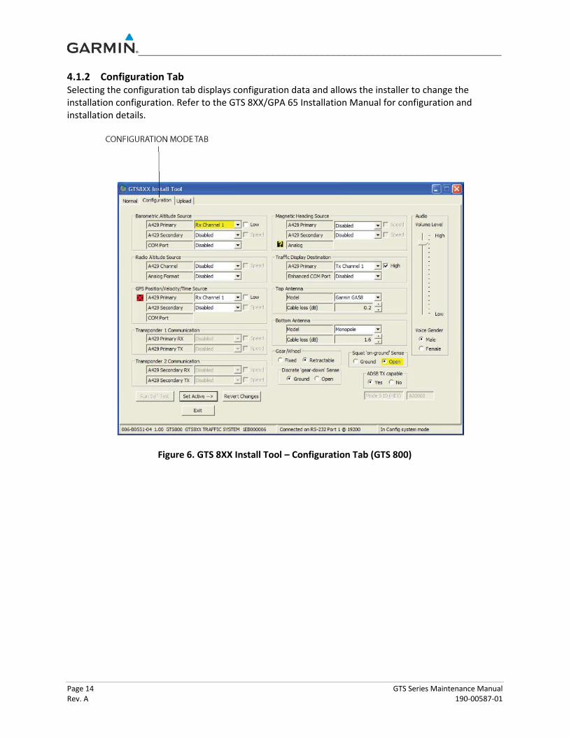
4.1.2 Configuration Tab Selecting the configuration tab displays configuration data and allows the installer to change the installation configuration. Refer to the GTS 8XX/GPA 65 Installation Manual for configuration and installation details.
Figure 6. GTS 8XX Install Tool – Configuration Tab (GTS 800)

_________________________________________________________________
GTS Series Maintenance Manual Page 15 190-00587-01 Rev. A
Figure 7. GTS 8XX Install Tool – Configuration Tab (GTS 820 and GTS 850)

_________________________________________________________________
Page 16 GTS Series Maintenance Manual Rev. A 190-00587-01
4.1.3 Upload Tab Selecting the upload tab displays version information for Boot Block, Region List, System, FPGA, Audio, Magnetic Variation. Boot Block updating is not allowed. Refer to the GTS 8XX/GPA 65 Installation Manual for configuration and installation details.
Figure 8. GTS 8XX Install Tool – Upload Tab

_________________________________________________________________
GTS Series Maintenance Manual Page 17 190-00587-01 Rev. A
5. SYSTEM (SELF) TEST The GTS 8XX provides a system test mode to verify the system is operating normally. The feature tests the (aural) alarm, attempts self calibration, and activates each display element in a pre-determined sequential pattern to aid in troubleshooting. The test takes ten seconds to complete.
NOTE Self tests may be performed indoors but signal multi-path from building walls may be a factor. If problems are experienced, self tests should be performed outside away from buildings, and where local traffic is not a factor.
To initiate the self test:
1. Turn the large FMS Knob to select the Map Page Group.
2. Turn the small FMS Knob to select the Traffic Map Page.
3. Turn the Range knob to set the range to 2/6 nm.
4. Press the TEST Softkey. or:
1. Press the MENU Key and turn the small FMS knob to select ‘Test Mode’.
2. Press the ENT Key.
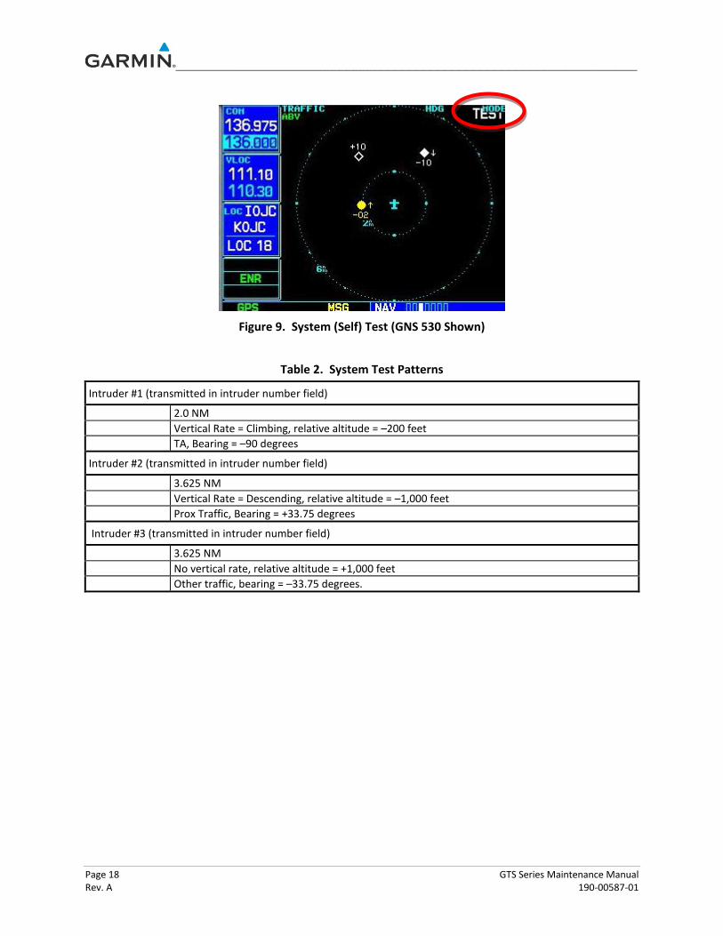
When the system test is initiated, a test pattern of traffic symbols is displayed on the Traffic Map Page (Figure 11; Table 2). If the system test passes, the following aural announcements are made:
GTS 800/820 - “TAS system Passed” or “TAS system Failed”
GTS 850 - “TCAS system Passed” or “TCAS system Failed”
When the system test is complete, the GTS 8XX enters Standby Mode. Any faults and flags are displayed on the normal tab of the GTS 8XX Install Tool Page. Faults that occur will be colored in red and flags will be colored in black. If self test fails, refer to the diagnostics data in Table 1 to determine the cause and possible action to take.
NOTE
Ensure that no intruder appears at close range to the aircraft. If the intruder appears at close range to the aircraft, verify that the mutual suppression line is connected between GTS 8XX and other L-band equipment (transponder, DME, etc.).
_________________________________________________________________
Page 18 GTS Series Maintenance Manual Rev. A 190-00587-01
Figure 9. System (Self) Test (GNS 530 Shown)
Table 2. System Test Patterns
Intruder #1 (transmitted in intruder number field)
2.0 NM
Vertical Rate = Climbing, relative altitude = –200 feet
TA, Bearing = –90 degrees
Intruder #2 (transmitted in intruder number field)
3.625 NM
Vertical Rate = Descending, relative altitude = –1,000 feet
Prox Traffic, Bearing = +33.75 degrees
Intruder #3 (transmitted in intruder number field)
3.625 NM
No vertical rate, relative altitude = +1,000 feet
Other traffic, bearing = –33.75 degrees.

_________________________________________________________________
GTS Series Maintenance Manual Page 19 190-00587-01 Rev. A
6. RAMP/RETURN TO SERVICE TEST
The following test can aid in troubleshooting and also be used as a return to service test. Using a ramp tester (TIC TR220 or equivalent) make the following set up and measurements to verify the correct operation of the GTS 8XX. To select a scenario that will properly converge and intercept the GTS 8XX, the GTS 8XX needs to be set to ground test mode. In order to enable ground test mode, the aircraft needs to be on the ground, in normal system mode and in standby.
1. Activate ground test mode by clicking ‘Enable’ in the normal tab of the GTS 8XX Install Tool (Figure 10). This simulates the GTS to be airborne at 50,000 ft with magnetic heading of 0°. Note: The GTS 8XX will not accept the Ground Test command unless the unit is in Standby and the squat switch indicates the aircraft is on the ground.
Figure 10. Ground Test Button
NOTE The GTS 8XX will not accept the Ground Test command unless the unit is in Standby and the squat switch indicates the aircraft is on the ground.
NOTE Configure Squat 'on-ground' sense as open if no sense switch is installed. Leave Air/Ground discrete Open. Configuration of Gear/Wheel as 'Fixed' will cause system to ignore the Gear Down and Locked discrete input.
2. Position the test set directional antenna with a clear line of sight to the GTS 8XX antenna per at 90 degrees.
3. With the GTS 8XX powered up and Standby indicated on the display, cycle the GTS 8XX to Operate.

_________________________________________________________________
Page 20 GTS Series Maintenance Manual Rev. A 190-00587-01
4. Select the following:
Set the intruder type as ATCRBS
Intruder Start Distance: 10 nm
Intruder Start Altitude: 50,000 ft.
Vertical Speed: 0 fpm
Velocity: 360 KTS
5. Initiate the intruder scenario and observe the display. Traffic should be acquired at approximately 10 NM at 90 degree bearing and co-altitude.
6. Observe intruder closes on the aircraft at a rate of 0.1 NM/sec. The intruder should transition from other traffic (displayed as an open diamond with 00 displayed above), to proximate traffic (displayed as a filled white diamond with 00 displayed above), to a traffic advisory (TA) alarm and the appropriate TA symbology (yellow filled circle with 00 displayed above, and an audio annunciation of "TRAFFIC! 3 O'CLOCK! AT ALTITUDE! 3 MILES!" displayed when the intruder approaches within 3 NM.
_________________________________________________________________
GTS Series Maintenance Manual Page 21 190-00587-01 Rev. A
7. REPLACING THE GTS 8XX
The following procedure is generic and may not apply to all installation situations. Check with the aircraft maintenance manual for specific removal and installation information. To remove:
1. If a cooling hose is attached to the unit, remove it from the air fitting and set aside.
2. Turn the harness connector jackscrews counterclockwise to disengage them from the unit.
3. Pull the harness connectors away from the unit to remove them.
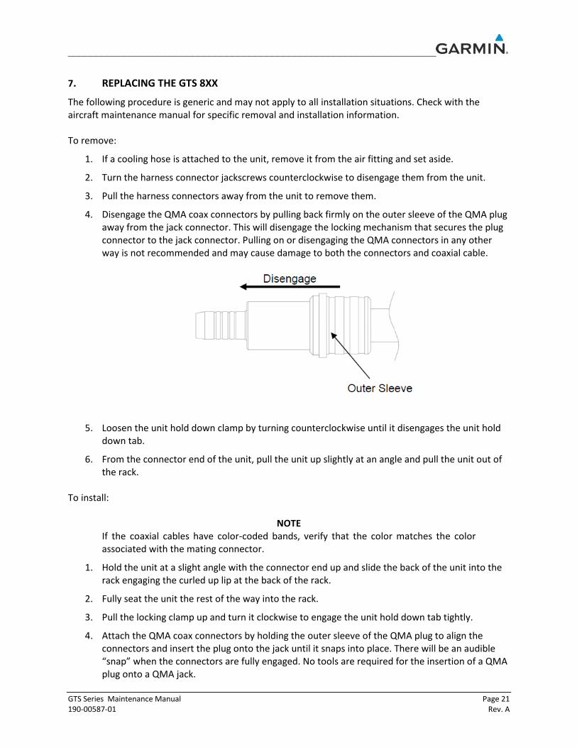
4. Disengage the QMA coax connectors by pulling back firmly on the outer sleeve of the QMA plug away from the jack connector. This will disengage the locking mechanism that secures the plug connector to the jack connector. Pulling on or disengaging the QMA connectors in any other way is not recommended and may cause damage to both the connectors and coaxial cable.
5. Loosen the unit hold down clamp by turning counterclockwise until it disengages the unit hold down tab.
6. From the connector end of the unit, pull the unit up slightly at an angle and pull the unit out of the rack.
To install:
NOTE If the coaxial cables have color-coded bands, verify that the color matches the color associated with the mating connector.
1. Hold the unit at a slight angle with the connector end up and slide the back of the unit into the rack engaging the curled up lip at the back of the rack.
2. Fully seat the unit the rest of the way into the rack.
3. Pull the locking clamp up and turn it clockwise to engage the unit hold down tab tightly.
4. Attach the QMA coax connectors by holding the outer sleeve of the QMA plug to align the connectors and insert the plug onto the jack until it snaps into place. There will be an audible “snap” when the connectors are fully engaged. No tools are required for the insertion of a QMA plug onto a QMA jack.
_________________________________________________________________
Page 22 GTS Series Maintenance Manual Rev. A 190-00587-01
5. Install the harness connectors and tighten the connector jackscrews to secure the connectors.
6. If a cooling hose was attached to the unit, reinstall the cooling hose to the air fitting.
7.1 GPA 65 To remove:
1. Remove the harness connector by rotating the locking barrel until it disengages from the mating connector.
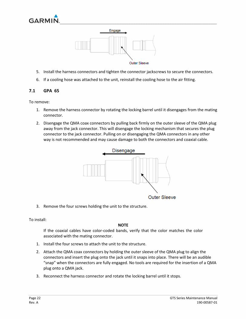
2. Disengage the QMA coax connectors by pulling back firmly on the outer sleeve of the QMA plug away from the jack connector. This will disengage the locking mechanism that secures the plug connector to the jack connector. Pulling on or disengaging the QMA connectors in any other way is not recommended and may cause damage to both the connectors and coaxial cable.
3. Remove the four screws holding the unit to the structure.
To install: NOTE
If the coaxial cables have color-coded bands, verify that the color matches the color associated with the mating connector.
1. Install the four screws to attach the unit to the structure.
2. Attach the QMA coax connectors by holding the outer sleeve of the QMA plug to align the connectors and insert the plug onto the jack until it snaps into place. There will be an audible “snap” when the connectors are fully engaged. No tools are required for the insertion of a QMA plug onto a QMA jack.
3. Reconnect the harness connector and rotate the locking barrel until it stops.


