AN1044: CP2615 Customization User Guide This document explains the options that are available for custom- ization on CP2615 fixed function USB devices. It contains information about obtaining a Vendor ID (VID) and Product ID (PID) for a CP2615 product and describes the steps necessary for customizing the device descrip- tors using Xpress Configurator within Simplicity Studio (http://www.silabs.com/simplici- ty). For a more detailed description of Xpress Configurator operation, please refer to AN721: CP210x/CP211x Device Customization Guide http://www.silabs.com/products/ Interface/Pages/interface-application-notes.aspx KEY POINTS • This document describes how to obtain and customize the VID, PID, and user identification strings for a CP2615-based product. • Customize the CP2615: • Audio Interface • GPIOs • CODEC configuration CP2615 Accessory USB Host (PC) Xpress Configurator CP2112 USB HID to I2C Bridge silabs.com | Building a more connected world. Rev. 0.4
Transcript
AN1044: CP2615 Customization UserGuide
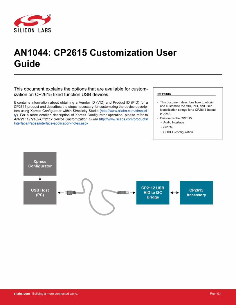
This document explains the options that are available for custom-ization on CP2615 fixed function USB devices.It contains information about obtaining a Vendor ID (VID) and Product ID (PID) for aCP2615 product and describes the steps necessary for customizing the device descrip-tors using Xpress Configurator within Simplicity Studio (http://www.silabs.com/simplici-ty). For a more detailed description of Xpress Configurator operation, please refer toAN721: CP210x/CP211x Device Customization Guide http://www.silabs.com/products/Interface/Pages/interface-application-notes.aspx
KEY POINTS
• This document describes how to obtainand customize the VID, PID, and useridentification strings for a CP2615-basedproduct.
• Customize the CP2615:• Audio Interface• GPIOs• CODEC configuration
CP2615Accessory
USB Host(PC)
Xpress Configurator
CP2112 USB HID to I2C
Bridge
silabs.com | Building a more connected world. Rev. 0.4
Each type of audio accessory that is connected to a USB host device must have a unique Vendor ID (VID), Product ID (PID), and serialnumber combination. This ID system uniquely identifies the different devices on the bus to avoid conflicts. The VID/PID must be uniquein that each USB device with the same VID/PID will use the same driver, and it is strongly recommended to make the PID unique to aparticular design. The USB devices of a given VID/PID combination can be serialized, which allows the operating system to track notonly a particular model, but also a specific board of that model.
Vendor IDs are owned by the vendor company and assigned by the USB Implementers Forum (USB-IF) only. Details about obtaining aunique VID can be found at www.usb.org/developers/vendor. To obtain the right to license the USB-IF logo, register the product's VIDand PID with USB-IF and submit the product to the USB-IF Compliance Program. USB-IF Compliance Program details are available atwww.usb.org/developers/compliance. Once the product is certified, it can be added to the USB-IF Integrators List, and the “CertifiedUSB” logo can be used on the product.
AN1044: CP2615 Customization User GuideUSB Vendor IDs and Product IDs
silabs.com | Building a more connected world. Rev. 0.4 | 2
The CP2615 has a number of properties that can be selected and changed by the customer. Simplicity Studio (http://www.silabs.com/simplicity) provides a tool, Xpress Configurator, to select the property configuration and to program it into a CP2615. It uses a USBconnection to a CP2112 as the programming interface for the CP2615, via I2C. Please see the CP2615-EK User's Guide for the boardschematic that demonstrates this connection: http://www.silabs.com/support/resources.ct-manuals.p-interface_usb-bridges.
The CP2615 configuration can also be set in the factory at production time for large orders. Contact your Silicon Laboratories salesrepresentative for details.
The CP2615 customization properties are organized into groups in the properties pane. The properties available in each group are de-scribed in the following sections.
Figure 2.1. CP2615 Xpress Configurator
AN1044: CP2615 Customization User GuideDevice Customization Software
silabs.com | Building a more connected world. Rev. 0.4 | 3
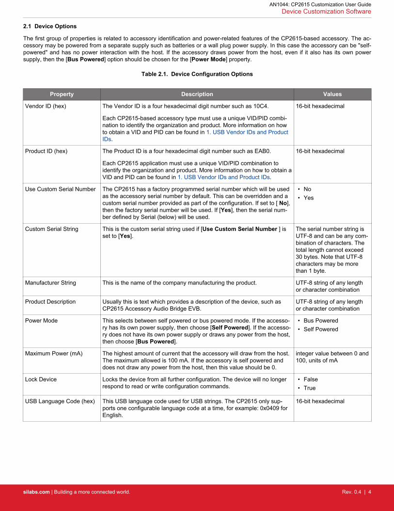
The first group of properties is related to accessory identification and power-related features of the CP2615-based accessory. The ac-cessory may be powered from a separate supply such as batteries or a wall plug power supply. In this case the accessory can be "self-powered" and has no power interaction with the host. If the accessory draws power from the host, even if it also has its own powersupply, then the [Bus Powered] option should be chosen for the [Power Mode] property.
Table 2.1. Device Configuration Options
Property Description Values
Vendor ID (hex) The Vendor ID is a four hexadecimal digit number such as 10C4.
Each CP2615-based accessory type must use a unique VID/PID combi-nation to identify the organization and product. More information on howto obtain a VID and PID can be found in 1. USB Vendor IDs and ProductIDs.
16-bit hexadecimal
Product ID (hex) The Product ID is a four hexadecimal digit number such as EAB0.
Each CP2615 application must use a unique VID/PID combination toidentify the organization and product. More information on how to obtain aVID and PID can be found in 1. USB Vendor IDs and Product IDs.
16-bit hexadecimal
Use Custom Serial Number The CP2615 has a factory programmed serial number which will be usedas the accessory serial number by default. This can be overridden and acustom serial number provided as part of the configuration. If set to [ No],then the factory serial number will be used. If [Yes], then the serial num-ber defined by Serial (below) will be used.
• No• Yes
Custom Serial String This is the custom serial string used if [Use Custom Serial Number ] isset to [Yes].
The serial number string isUTF-8 and can be any com-bination of characters. Thetotal length cannot exceed30 bytes. Note that UTF-8characters may be morethan 1 byte.
Manufacturer String This is the name of the company manufacturing the product. UTF-8 string of any lengthor character combination
Product Description Usually this is text which provides a description of the device, such asCP2615 Accessory Audio Bridge EVB.
UTF-8 string of any lengthor character combination
Power Mode This selects between self powered or bus powered mode. If the accesso-ry has its own power supply, then choose [Self Powered]. If the accesso-ry does not have its own power supply or draws any power from the host,then choose [Bus Powered].
• Bus Powered• Self Powered
Maximum Power (mA) The highest amount of current that the accessory will draw from the host.The maximum allowed is 100 mA. If the accessory is self powered anddoes not draw any power from the host, then this value should be 0.
integer value between 0 and100, units of mA
Lock Device Locks the device from all further configuration. The device will no longerrespond to read or write configuration commands.
• False• True
USB Language Code (hex) This USB language code used for USB strings. The CP2615 only sup-ports one configurable language code at a time, for example: 0x0409 forEnglish.
16-bit hexadecimal
AN1044: CP2615 Customization User GuideDevice Customization Software
silabs.com | Building a more connected world. Rev. 0.4 | 4
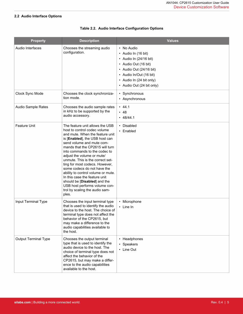
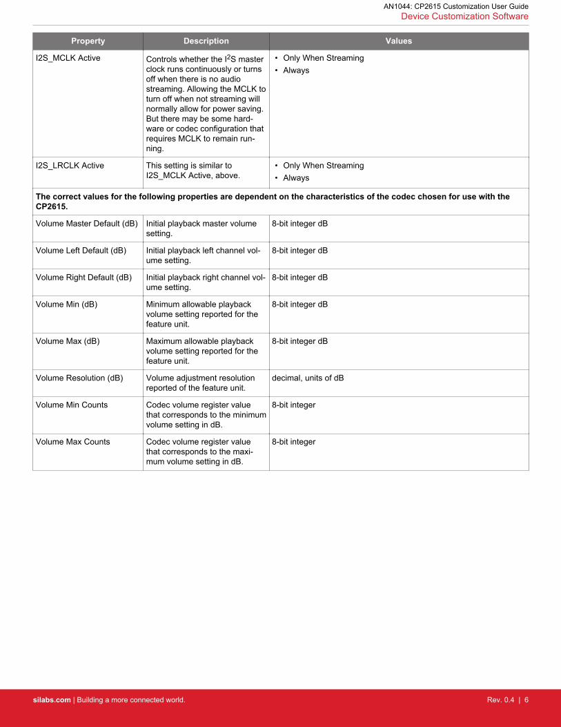
2.2 Audio Interface Options
Table 2.2. Audio Interface Configuration Options
Property Description Values
Audio Interfaces Chooses the streaming audioconfiguration.
• No Audio• Audio In (16 bit)• Audio In (24/16 bit)• Audio Out (16 bit)• Audio Out (24/16 bit)• Audio In/Out (16 bit)• Audio In (24 bit only)• Audio Out (24 bit only)
Clock Sync Mode Chooses the clock synchroniza-tion mode.
• Synchronous• Asynchronous
Audio Sample Rates Chooses the audio sample ratesin kHz to be supported by theaudio accessory.
• 44.1• 48• 48/44.1
Feature Unit The feature unit allows the USBhost to control codec volumeand mute. When the feature unitis [Enabled], the USB host cansend volume and mute com-mands that the CP2615 will turninto commands to the codec toadjust the volume or mute/unmute. This is the correct set-ting for most codecs. However,some codecs do not have theability to control volume or mute.In this case the feature unitshould be [Disabled] and theUSB host performs volume con-trol by scaling the audio sam-ples.
• Disabled• Enabled
Input Terminal Type Chooses the input terminal typethat is used to identify the audiodevice to the host. The choice ofterminal type does not affect thebehavior of the CP2615, butmay make a difference to theaudio capabilities available tothe host.
• Microphone• Line In
Output Terminal Type Chooses the output terminaltype that is used to identify theaudio device to the host. Thechoice of terminal type does notaffect the behavior of theCP2615, but may make a differ-ence to the audio capabilitiesavailable to the host.
• Headphones• Speakers• Line Out
AN1044: CP2615 Customization User GuideDevice Customization Software
silabs.com | Building a more connected world. Rev. 0.4 | 5
Property Description Values
I2S_MCLK Active Controls whether the I2S masterclock runs continuously or turnsoff when there is no audiostreaming. Allowing the MCLK toturn off when not streaming willnormally allow for power saving.But there may be some hard-ware or codec configuration thatrequires MCLK to remain run-ning.
• Only When Streaming• Always
I2S_LRCLK Active This setting is similar toI2S_MCLK Active, above.
• Only When Streaming• Always
The correct values for the following properties are dependent on the characteristics of the codec chosen for use with theCP2615.
Volume Left Default (dB) Initial playback left channel vol-ume setting.
8-bit integer dB
Volume Right Default (dB) Initial playback right channel vol-ume setting.
8-bit integer dB
Volume Min (dB) Minimum allowable playbackvolume setting reported for thefeature unit.
8-bit integer dB
Volume Max (dB) Maximum allowable playbackvolume setting reported for thefeature unit.
8-bit integer dB
Volume Resolution (dB) Volume adjustment resolutionreported of the feature unit.
decimal, units of dB
Volume Min Counts Codec volume register valuethat corresponds to the minimumvolume setting in dB.
8-bit integer
Volume Max Counts Codec volume register valuethat corresponds to the maxi-mum volume setting in dB.
8-bit integer
AN1044: CP2615 Customization User GuideDevice Customization Software
silabs.com | Building a more connected world. Rev. 0.4 | 6
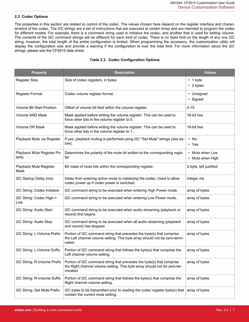
2.3 Codec Options
The properties in this section are related to control of the codec. The values chosen here depend on the register interface and charac-teristics of the codec. The I2C strings are a set of instructions that are executed at certain times and are intended to program the codecfor different modes. For example, there is a command string used to initialize the codec, and another that is used for setting volume.The contents of the I2C command strings will be different for each kind of codec. There is no fixed limit on the length of any one I2Cstring; however, the total length of the entire configuration is limited. When programming the accessory, the customization utility willdisplay the configuration size and provide a warning if the configuration is over the total limit. For more information about the I2Cstrings, please see the CP2615 data sheet.
Table 2.3. Codec Configuration Options
Property Description Values
Register Size Size of codec registers, in bytes. • 1 byte• 2 bytes
Register Format Codec volume register format. • Unsigned• Signed
Volume Bit Start Position Offset of volume bit field within the volume register. 0-15
Volume AND Mask Mask applied before writing the volume register. This can be used toforce other bits in the volume register to 0.
16-bit hex
Volume OR Mask Mask applied before writing the volume register. This can be used toforce other bits in the volume register to 1.
16-bit hex
Playback Mute via Register If yes, playback muting is performed using I2C "Set Mute" strings (see be-low).
• No• Yes
Playback Mute Register Po-larity
Determines the polarity of the mute bit written to the corresponding regis-ter.
• Mute when Low• Mute when High
Playback Mute RegisterMask
Bit mask of mute bits within the corresponding register. 2-byte, left justified
I2C Startup Delay (ms) Delay from entering active mode to initializing the codec. Used to allowcodec power up if codec power is switched.
integer ms
I2C String: Codec Initialize I2C command string to be executed when entering High Power mode. array of bytes
I2C String: Codec High->Low
I2C command string to be executed when entering Low Power mode. array of bytes
I2C String: Audio Start I2C command string to be executed when audio streaming (playback orrecord) first begins.
array of bytes
I2C String: Audio Stop I2C command string to be executed when all audio streaming (playbackand record) has stopped.
array of bytes
I2C String: L-Volume Prefix Portion of I2C command string that precedes the byte(s) that comprisethe Left channel volume setting. This byte array should not be zero-termi-nated.
array of bytes
I2C String: L-Volume Suffix Portion of I2C command string that follows the byte(s) that comprise theLeft channel volume setting.
array of bytes
I2C String: R-Volume Prefix Portion of I2C command string that precedes the byte(s) that comprisethe Right channel volume setting. This byte array should not be zero-ter-minated.
array of bytes
I2C String: R-Volume Suffix Portion of I2C command string that follows the byte(s) that comprise theRight channel volume setting.
array of bytes
I2C String: Get Mute Prefix I2C bytes to be transmitted prior to reading the codec register byte(s) thatcontain the current mute setting.
array of bytes
AN1044: CP2615 Customization User GuideDevice Customization Software
silabs.com | Building a more connected world. Rev. 0.4 | 7
Property Description Values
I2C String: Set Mute Prefix I2C bytes to be transmitted prior to writing the mute setting byte(s) to thecodec. This byte array should not be zero-terminated.
array of bytes
I2C String: Set Mute Suffix I2C bytes to be transmitted after writing the mute setting byte(s) to the co-dec.
array of bytes
I2C String: Set Rate 44.1 I2C command string to be executed when host sets sample rate to 44.1kHz.
array of bytes
I2C String: Set Rate 48.0 I2C command string to be executed when host sets sample rate to 48kHz.
array of bytes
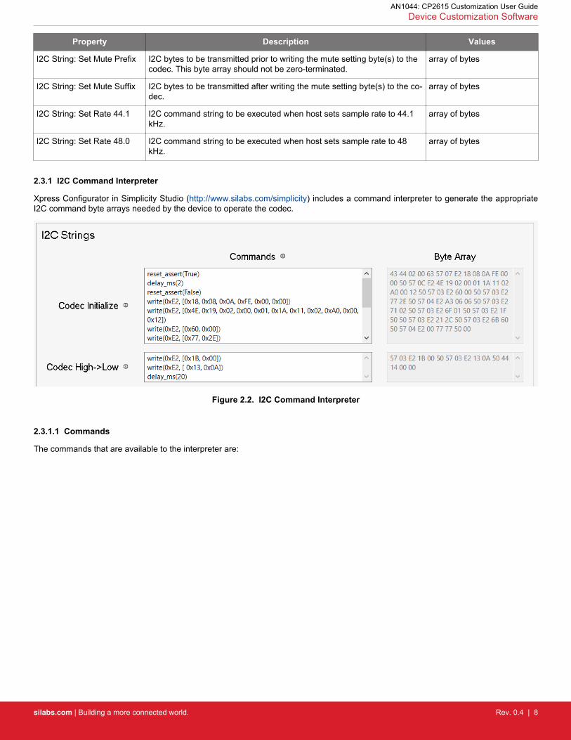
2.3.1 I2C Command Interpreter
Xpress Configurator in Simplicity Studio (http://www.silabs.com/simplicity) includes a command interpreter to generate the appropriateI2C command byte arrays needed by the device to operate the codec.
Figure 2.2. I2C Command Interpreter
2.3.1.1 Commands
The commands that are available to the interpreter are:
AN1044: CP2615 Customization User GuideDevice Customization Software
silabs.com | Building a more connected world. Rev. 0.4 | 8
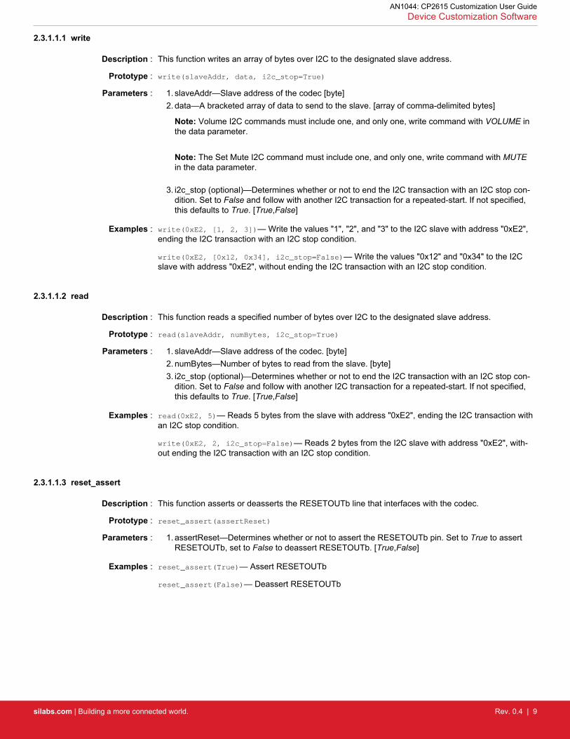
Description : This function writes an array of bytes over I2C to the designated slave address.
Prototype : write(slaveAddr, data, i2c_stop=True)
Parameters : 1. slaveAddr—Slave address of the codec [byte]2. data—A bracketed array of data to send to the slave. [array of comma-delimited bytes]
Note: Volume I2C commands must include one, and only one, write command with VOLUME inthe data parameter.
Note: The Set Mute I2C command must include one, and only one, write command with MUTEin the data parameter.
3. i2c_stop (optional)—Determines whether or not to end the I2C transaction with an I2C stop con-dition. Set to False and follow with another I2C transaction for a repeated-start. If not specified,this defaults to True. [True,False]
Examples : write(0xE2, [1, 2, 3])— Write the values "1", "2", and "3" to the I2C slave with address "0xE2",ending the I2C transaction with an I2C stop condition.
write(0xE2, [0x12, 0x34], i2c_stop=False)— Write the values "0x12" and "0x34" to the I2Cslave with address "0xE2", without ending the I2C transaction with an I2C stop condition.
2.3.1.1.2 read
Description : This function reads a specified number of bytes over I2C to the designated slave address.
Parameters : 1. slaveAddr—Slave address of the codec. [byte]2. numBytes—Number of bytes to read from the slave. [byte]3. i2c_stop (optional)—Determines whether or not to end the I2C transaction with an I2C stop con-
dition. Set to False and follow with another I2C transaction for a repeated-start. If not specified,this defaults to True. [True,False]
Examples : read(0xE2, 5)— Reads 5 bytes from the slave with address "0xE2", ending the I2C transaction withan I2C stop condition.
write(0xE2, 2, i2c_stop=False)— Reads 2 bytes from the I2C slave with address "0xE2", with-out ending the I2C transaction with an I2C stop condition.
2.3.1.1.3 reset_assert
Description : This function asserts or deasserts the RESETOUTb line that interfaces with the codec.
Prototype : reset_assert(assertReset)
Parameters : 1. assertReset—Determines whether or not to assert the RESETOUTb pin. Set to True to assertRESETOUTb, set to False to deassert RESETOUTb. [True,False]
Examples : reset_assert(True)— Assert RESETOUTb
reset_assert(False)— Deassert RESETOUTb
AN1044: CP2615 Customization User GuideDevice Customization Software
silabs.com | Building a more connected world. Rev. 0.4 | 9
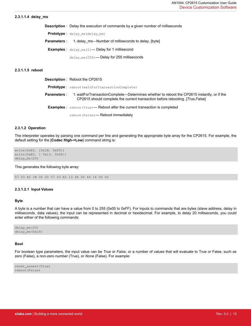
2.3.1.1.4 delay_ms
Description : Delay the execution of commands by a given number of milliseconds
Prototype : delay_ms(delay_ms)
Parameters : 1. delay_ms—Number of milliseconds to delay. [byte]
Examples : delay_ms(1)— Delay for 1 millisecond
delay_ms(255)— Delay for 255 milliseconds
2.3.1.1.5 reboot
Description : Reboot the CP2615
Prototype : reboot(waitForTransactionComplete)
Parameters : 1. waitForTransactionComplete—Determines whether to reboot the CP2615 instantly, or if theCP2615 should complete the current transaction before rebooting. [True,False]
Examples : reboot(True)— Reboot after the current transaction is completed
reboot(False)— Reboot immediately
2.3.1.2 Operation
The interpreter operates by parsing one command per line and generating the appropriate byte array for the CP2615. For example, thedefault setting for the [Codec High->Low] command string is:
A byte is a number that can have a value from 0 to 255 (0x00 to 0xFF). For inputs to commands that are bytes (slave address, delay inmilliseconds, data values), the input can be represented in decimal or hexidecimal. For example, to delay 20 milliseconds, you couldenter either of the following commands:
delay_ms(20)delay_ms(0x14)
Bool
For boolean type parameters, the input value can be True or False, or a number of values that will evaluate to True or False, such aszero (False), a non-zero number (True), or None (False). For example:
reset_assert(True)reboot(False)
AN1044: CP2615 Customization User GuideDevice Customization Software
silabs.com | Building a more connected world. Rev. 0.4 | 10
Data Array
The 2.3.1.1.1 write command has a parameter called data that is an array of byte values. This array is represented by a bracketed,comma-delimited list of bytes. These bytes follow the same rules as above, so they can be represented in decimal or hexidecimal (ifprefixed by '0x'). For example, this is a valid write command with a data array:
write(0xE2, [0x18, 0x08, 0x0A, 254, 0, 0])
For two specific cases, the write command can also contain a keyword.
For the [Set L-Volume] and [Set R-Volume] command strings, the commands must contain at least one, and only one, write with VOL-UME as one of the data array values. For example:
write(0xE2, [0x04, VOLUME])
For the [Set Mute] command string, the commands must contain at least one, and only one, write with MUTE as one of the data arrayvalues. For example:
write(0xE2, [0x18, MUTE])
Optional Parameters
The 2.3.1.1.1 write and 2.3.1.1.2 read commands have an additional optional parameter called i2c_stop that can be omitted. If the para-mter is omitted, the value is set to a default specified in the command description. For example, these are valid uses of the write com-mand with the i2c_stop parameter:
In this last case, the i2c_stop parameter is not specified, so it is set to its default value, True.
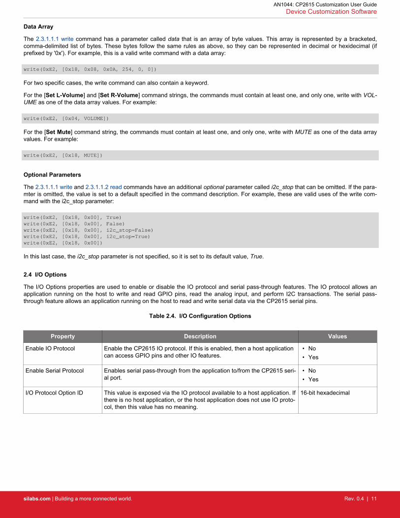
2.4 I/O Options
The I/O Options properties are used to enable or disable the IO protocol and serial pass-through features. The IO protocol allows anapplication running on the host to write and read GPIO pins, read the analog input, and perform I2C transactions. The serial pass-through feature allows an application running on the host to read and write serial data via the CP2615 serial pins.
Table 2.4. I/O Configuration Options
Property Description Values
Enable IO Protocol Enable the CP2615 IO protocol. If this is enabled, then a host applicationcan access GPIO pins and other IO features.
• No• Yes
Enable Serial Protocol Enables serial pass-through from the application to/from the CP2615 seri-al port.
• No• Yes
I/O Protocol Option ID This value is exposed via the IO protocol available to a host application. Ifthere is no host application, or the host application does not use IO proto-col, then this value has no meaning.
16-bit hexadecimal
AN1044: CP2615 Customization User GuideDevice Customization Software
silabs.com | Building a more connected world. Rev. 0.4 | 11
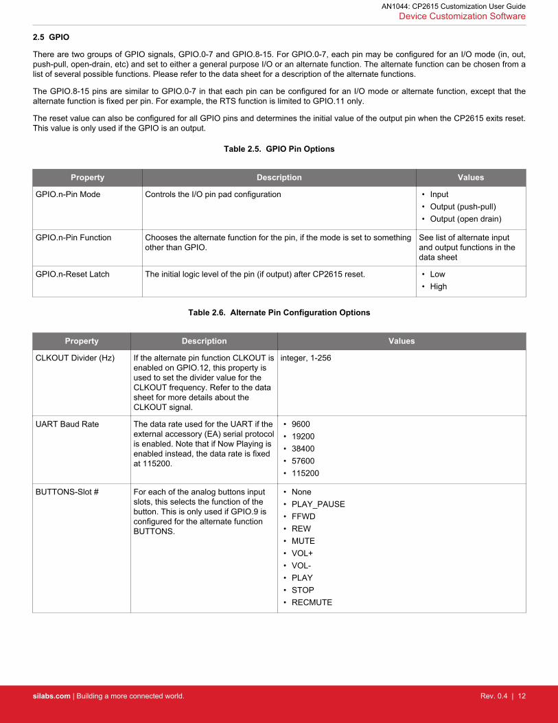
2.5 GPIO
There are two groups of GPIO signals, GPIO.0-7 and GPIO.8-15. For GPIO.0-7, each pin may be configured for an I/O mode (in, out,push-pull, open-drain, etc) and set to either a general purpose I/O or an alternate function. The alternate function can be chosen from alist of several possible functions. Please refer to the data sheet for a description of the alternate functions.
The GPIO.8-15 pins are similar to GPIO.0-7 in that each pin can be configured for an I/O mode or alternate function, except that thealternate function is fixed per pin. For example, the RTS function is limited to GPIO.11 only.
The reset value can also be configured for all GPIO pins and determines the initial value of the output pin when the CP2615 exits reset.This value is only used if the GPIO is an output.
Table 2.5. GPIO Pin Options
Property Description Values
GPIO.n-Pin Mode Controls the I/O pin pad configuration • Input• Output (push-pull)• Output (open drain)
GPIO.n-Pin Function Chooses the alternate function for the pin, if the mode is set to somethingother than GPIO.
See list of alternate inputand output functions in thedata sheet
GPIO.n-Reset Latch The initial logic level of the pin (if output) after CP2615 reset. • Low• High
Table 2.6. Alternate Pin Configuration Options
Property Description Values
CLKOUT Divider (Hz) If the alternate pin function CLKOUT isenabled on GPIO.12, this property isused to set the divider value for theCLKOUT frequency. Refer to the datasheet for more details about theCLKOUT signal.
integer, 1-256
UART Baud Rate The data rate used for the UART if theexternal accessory (EA) serial protocolis enabled. Note that if Now Playing isenabled instead, the data rate is fixedat 115200.
• 9600• 19200• 38400• 57600• 115200
BUTTONS-Slot # For each of the analog buttons inputslots, this selects the function of thebutton. This is only used if GPIO.9 isconfigured for the alternate functionBUTTONS.
AN1044: CP2615 Customization User GuideDevice Customization Software
silabs.com | Building a more connected world. Rev. 0.4 | 12
3. Revision History
3.1 Revision 0.1
October 21st, 2016
Initial revision.
3.2 Revision 0.2
April 10th, 2017
Updated for Xpress Configurator.
3.3 Revision 0.3
April 18th, 2017
Minor fixes:• [Clock Sync Mode] description listed a restriction for Asynchronous mode that doesn't exit.• [BUTTONS-Slot#] listed some invalid options which were removed.• [Audio Interfaces] did not list all possible options. It was missing Audio In (24 bit only) and Audio Out (24 bit only).
3.4 Revision 0.4
April 26th, 2017
Added [Input Terminal Type] and [Output Terminal Type] options to Audio Interface Options.
AN1044: CP2615 Customization User GuideRevision History
silabs.com | Building a more connected world. Rev. 0.4 | 13
http://www.silabs.com
Silicon Laboratories Inc.400 West Cesar ChavezAustin, TX 78701USA
Simplicity StudioOne-click access to MCU and wireless tools, documentation, software, source code libraries & more. Available for Windows, Mac and Linux!
IoT Portfoliowww.silabs.com/IoT
SW/HWwww.silabs.com/simplicity
Qualitywww.silabs.com/quality
Support and Communitycommunity.silabs.com
DisclaimerSilicon Labs intends to provide customers with the latest, accurate, and in-depth documentation of all peripherals and modules available for system and software implementers using or intending to use the Silicon Labs products. Characterization data, available modules and peripherals, memory sizes and memory addresses refer to each specific device, and "Typical" parameters provided can and do vary in different applications. Application examples described herein are for illustrative purposes only. Silicon Labs reserves the right to make changes without further notice and limitation to product information, specifications, and descriptions herein, and does not give warranties as to the accuracy or completeness of the included information. Silicon Labs shall have no liability for the consequences of use of the information supplied herein. This document does not imply or express copyright licenses granted hereunder to design or fabricate any integrated circuits. The products are not designed or authorized to be used within any Life Support System without the specific written consent of Silicon Labs. A "Life Support System" is any product or system intended to support or sustain life and/or health, which, if it fails, can be reasonably expected to result in significant personal injury or death. Silicon Labs products are not designed or authorized for military applications. Silicon Labs products shall under no circumstances be used in weapons of mass destruction including (but not limited to) nuclear, biological or chemical weapons, or missiles capable of delivering such weapons.
Trademark InformationSilicon Laboratories Inc.® , Silicon Laboratories®, Silicon Labs®, SiLabs® and the Silicon Labs logo®, Bluegiga®, Bluegiga Logo®, Clockbuilder®, CMEMS®, DSPLL®, EFM®, EFM32®, EFR, Ember®, Energy Micro, Energy Micro logo and combinations thereof, "the world’s most energy friendly microcontrollers", Ember®, EZLink®, EZRadio®, EZRadioPRO®, Gecko®, ISOmodem®, Precision32®, ProSLIC®, Simplicity Studio®, SiPHY®, Telegesis, the Telegesis Logo®, USBXpress® and others are trademarks or registered trademarks of Silicon Labs. ARM, CORTEX, Cortex-M3 and THUMB are trademarks or registered trademarks of ARM Holdings. Keil is a registered trademark of ARM Limited. All other products or brand names mentioned herein are trademarks of their respective holders.


![Guide AN1044: CP2615 Customization User Interface/Pages ......If the accesso-ry has its own power supply, then choose [ Self Powered]. If the accesso-ry does not have its own power](https://static.documents.pub/doc/80x56/5f494ff772862a21696b19be/guide-an1044-cp2615-customization-user-interfacepages-if-the-accesso-ry.jpg)


