Always Air. Always Accurate. Canisters and Bags Guide to Air Sampling www.AirToxics.com Soil Gas Vapor Intrusion Property Redevelopment Ambient Air Monitoring Indoor Air Quality Waste-to-Energy
Transcript
Always Air. Always Accurate.
Canisters and Bags
Guide toAir Sampling
www.AirToxics.com
Soil Gas
Vapor Intrusion
Property Redevelopment
Ambient Air Monitoring
Indoor Air Quality
Waste-to-Energy
Eurofins Air Toxics, Inc.Guide to Whole Air Sampling – Canisters and Bags
Eurofins Air Toxics Inc. presents this guide as a resource for individuals engaged in airsampling. Air sampling can be more involved than water or soil sampling due to thereactivity of chemical compounds in the gas matrix and sample interaction with theequipment and media used. Ensuring that air samples are collected properly is an importantstep in acquiring meaningful analytical results. This guide is not a substitute for experienceand cannot sufficiently address the multitude of field conditions. Note that this guide isintended for projects involving whole air sampling of volatile organic compounds (VOCs) incanisters and Tedlar® bags. Eurofins Air Toxics provides the “Guide to Sorbent-BasedSampling - Volatiles and Semi-Volatiles” for other types of sampling.
1.1 Whole Air Sampling of VOCs
There are three general ways to collect compounds in a gas phase sample. A sampler maycollect the gas sample in a container, actively pump the vapor through a sorbent tube,solution or filter, or rely on passive sample collection onto a sorbent bed. This guidefocuses on collecting a sample in the most common air sampling containers, Summacanisters and bags. The sample may be collected in the container either passively, relying onan evacuated canister to drive the sample collection, or actively using a pump to fill thecontainer. The container is subsequently sealed and transported to the laboratory foranalysis. The sample is referred to as a “whole air sample” and the compounds remain inthe gas matrix inside the container.
As a general rule, whole air sampling is appropriate when target compounds are chemicallystable and have vapor pressures greater than 0.1 torr at 25°C and 760mm Hg (EPA standardambient conditions). Performance of a given compound in a whole air sample is dependentupon its chemical properties, the matrix of the sample, and the degree of inertness of thesample container.
1.2 Choosing Between Canisters and Bags
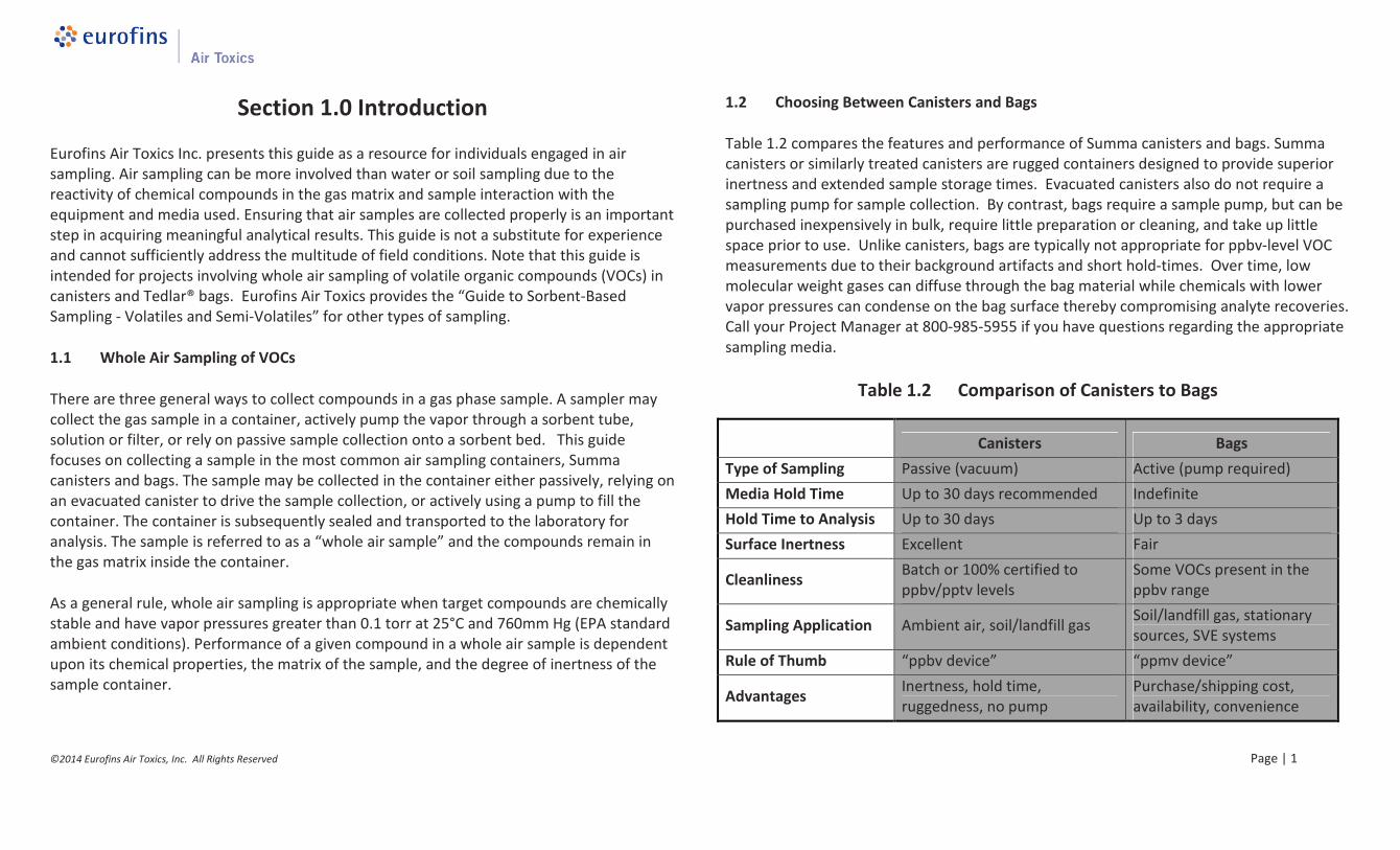
Table 1.2 compares the features and performance of Summa canisters and bags. Summacanisters or similarly treated canisters are rugged containers designed to provide superiorinertness and extended sample storage times. Evacuated canisters also do not require asampling pump for sample collection. By contrast, bags require a sample pump, but can bepurchased inexpensively in bulk, require little preparation or cleaning, and take up littlespace prior to use. Unlike canisters, bags are typically not appropriate for ppbv-level VOCmeasurements due to their background artifacts and short hold-times. Over time, lowmolecular weight gases can diffuse through the bag material while chemicals with lowervapor pressures can condense on the bag surface thereby compromising analyte recoveries.Call your Project Manager at 800-985-5955 if you have questions regarding the appropriatesampling media.
Table 1.2 Comparison of Canisters to Bags
Canisters Bags
Type of Sampling Passive (vacuum) Active (pump required)
Media Hold Time Up to 30 days recommended Indefinite
Hold Time to Analysis Up to 30 days Up to 3 days
Surface Inertness Excellent Fair
CleanlinessBatch or 100% certified toppbv/pptv levels
Some VOCs present in theppbv range
Sampling Application Ambient air, soil/landfill gasSoil/landfill gas, stationarysources, SVE systems
Rule of Thumb “ppbv device” “ppmv device”
AdvantagesInertness, hold time,ruggedness, no pump
This section provides a description of air sampling canisters, practical considerations forsampling, and step-by-step instructions for collecting grab and integrated samples.Photographs illustrate the correct way to assemble the various sampling components.Tables provide detailed information on many operational factors that ultimately influencethe quality of the data obtained from a canister sample.
2.1 Introduction to Canisters
An air sampling canister is a container for collecting a whole airsample. A canister may be spherical or cylindrical and isconstructed of specially treated stainless steel. The canister isprepared for sampling by evacuating the contents to a vacuumof approximately 29.9 inches of Mercury (in Hg). Opening thestainless steel bellows valve allows the air sample to enter thecanister. Flow controllers can be utilized to restrict the flowand allow for collection at a desired flow rate or over a desiredrange. When the sample has been collected, the valve is closed and the canister is returnedto the laboratory. Canisters range in volume from less than 1 liter (L) to 6 L. In general, 6 Lcanisters are used to collect ambient air samples and samples requiring time integrationgreater than 2 hours. One liter canisters are typically used for taking high concentration(i.e., greater than 5 ppbv) samples not requiring time integration such as soil vapor.
2.1.1 Summa Canister
A Summa canister is a stainless steel container that has had the internal surfaces speciallypassivated using a “Summa” process. This process combines an electropolishing step with achemical deactivation step to produce a surface that is nearly chemically inert. A Summasurface has the appearance of a mirror: bright, shiny and smooth. The degree of chemicalinertness of a whole air sample container is crucial to minimizing reactions with the sample
and maximizing recovery of target compounds from the container. Eurofins Air Toxicsmaintains a large inventory of Summa canisters in 1 and 6 L volumes.
2.1.2 Canister Certification
Eurofins Air Toxics provides two types of canister cleaning certification, batch and 100%,depending upon the requirements of the project. The batch certification process is mostappropriate for routine ambient air applications and high concentration applications such assoil vapor and landfill gas monitoring. The batch certification process begins by cleaning aset of canisters using a combination of dilution, heat and high vacuum. The cleaning batch iscertified by analyzing a percentage of canisters for approximately 60 VOCs using GC/MS.The batch meets cleaning requirements if the target compound concentrations are below0.2 ppbv. Alternatively, the 100% certification (i.e., individual certification) process istypically required for ambient and indoor air applications driven by risk assessment orlitigation requiring pptv (parts per trillion by volume) sensitivity. If 100% certification isrequired, canisters are individually certified for a client-specific list of target compoundsusing GC/MS. When the 100% certified canisters are shipped, the analytical documentationdemonstrating that they are free of the target compounds down to the project reportinglimits is emailed to the client. When sampling with certified media, it is important to notethat all media is certified as a train and must be sampled as such (i.e., a particular flowcontroller goes with a particular canister and is labeled as such).
Specify whether your project requires batch or 100% canister certification.
2.1.3 Canister Hold Time
Media Hold Time: Unlike water and soil environmental samples, which are collected insingle-use, disposable vials and jars, air samples are collected in reusable summa canisters.Eurofins Air Toxics requires that canisters be returned within 15 days of receipt toeffectively manage our inventory and to insure canisters meet performance requirements inthe field. Evacuated canisters have a finite timeframe before the canisters naturally lose
vacuum during storage. Using canisters beyond 15 days increases the risk of havingunacceptable initial vacuum at the start of sampling.
Sample Hold Time: EPA Method TO-15 cites a sample hold time of up to 30 days for mostVOCs. Several non-routine compounds, such as bis(chloromethyl)ether, degrade quicklyand demonstrate low recovery even after 7 days. Reactive sulfur compounds such ashydrogen disulfide and methyl, ethyl, and butyl mercaptan are not amenable to storage instainless steel summa canister, and either fused silica lined (FSL) canisters or Tedlar bags arerequired for sample collection.
2.2 Associated Canister Hardware
Associated hardware used with the canister includes the valve, brass cap, particulate filterand vacuum gauge. (Flow controllers are covered in detail in section 3.2.)
2.2.1 Valve
An industry standard 1/4” stainless steel bellows valve is mounted at the top of the canister.The valve maintains the vacuum in the canister prior to sampling and seals the canister oncethe sample has been collected. No more than a half turn by hand is required to open thevalve. Do not over-tighten the valve after sampling or it may become damaged. A damagedvalve can leak, possibly compromising the sample. Some canisters have a metal cage nearthe top to protect the valve.
To protect the valve and provide secure connections in the field, a replaceable fitting isattached to all canisters. As threads wear and require replacement, new fittings can beinstalled at the laboratory prior to shipping to the field. You will need a 1/2” wrench tosecure the fitting while connecting or removing the required equipment to the canister.
2.2.2 Brass Cap
Each canister comes with a brass cap (i.e., Swagelok 1/4” plug) secured to the inlet of thevalve assembly. The cap serves two purposes. First, it ensures that there is no loss ofvacuum due to a leaky valve or a valve that is accidentally opened during handling. Second,it prevents dust and other particulate matter from damaging the valve. The cap is removedprior to sampling and replaced following sample collection.
Always replace the brass cap following canister sampling.
2.2.3 Particulate Filter
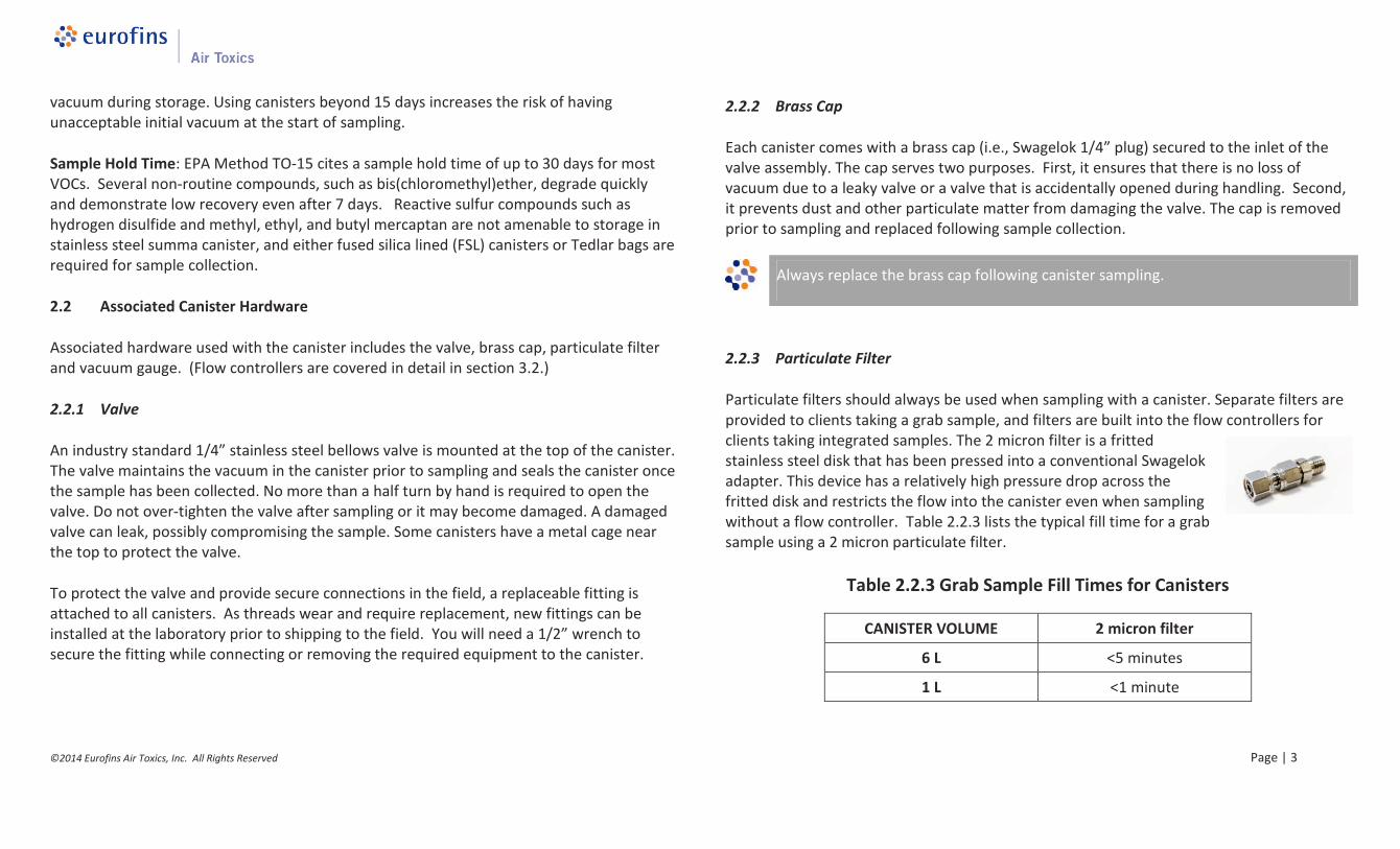
Particulate filters should always be used when sampling with a canister. Separate filters areprovided to clients taking a grab sample, and filters are built into the flow controllers forclients taking integrated samples. The 2 micron filter is a frittedstainless steel disk that has been pressed into a conventional Swagelokadapter. This device has a relatively high pressure drop across thefritted disk and restricts the flow into the canister even when samplingwithout a flow controller. Table 2.2.3 lists the typical fill time for a grabsample using a 2 micron particulate filter.
All fittings on the sampling hardware are 1/4” Swagelok, and a 9/16” wrench is used toassemble the hardware. A 1/2” wrench is also required to tighten fittings onto a unionconnector. Compression fittings should be used for all connections. Never use tube-in-tubeconnections. It is critical to avoid leaks in the sampling train. Leaks of ambient air throughfittings between pieces of the sampling train will dilute the sample and cause the canister tofill at a faster rate than desired. Eurofins Air Toxics can provide the necessary fittings andferrules if requested.
2.2.5 Vacuum Gauge
A vacuum gauge is used to measure the initial vacuum of the canister before sampling, andthe final vacuum upon completion. A gauge can also be used to monitor the fill rate of thecanister when collecting an integrated sample. Eurofins Air Toxics provides 2 types ofgauges. For grab sampling, a test gauge checks initial and final vacuums only and is not to besampled through. For integrated sampling a gauge is built into the flow controller and maybe used for monitoring initial and final vacuums, as well as monitoring the fill rate of thecanister. Both gauges are considered to be rough gauges, intended to obtain a relativemeasure of vacuum change. Accuracy of these field gauges are generally on the order of +/-5 in Hg. Individuals with work plans that outline specific gauge reading requirements arestrongly encouraged to purchase and maintain their own gauges in the field. In specialcases, a laboratory-grade, NIST-traceable vacuum gauge can be provided upon request.
The vacuum gauges that are routinely provided are intended as a rough gaugemeasurement device (+/-5 in Hg accuracy).
There are two basic modes of canister sampling: grab and integrated. A grab sample istaken over a short interval (i.e., 1-5 minutes) to provide a point-in-time sampleconcentration, while an integrated sample is taken over a specified duration or utilizing aspecified flow rate. In both modes the canister vacuum is used to draw the sample into thecanister. This is commonly referred to as passive canister sampling. Sections 3.1 and 3.2detail procedures for grab and integrated sampling, and section 3.3 provides proceduresspecific to soil vapor collection.
Regardless of the type of canister samples collected, the following rules apply:
DO NOT use canister to collect explosive substances, radiological or biological agents,corrosives, extremely toxic substances or other hazardous materials. It is illegal to shipsuch substances and you will be liable for damages.
ALWAYS use a filter when sampling. NEVER allow liquids (including water) or corrosivevapors to enter canister.
DO NOT attach labels to the surface of the canister or write on the canister; you will beliable for cleaning charges.
DO NOT over tighten the valve, and remember to replace the brass cap.
IF the canister is returned in unsatisfactory condition, you will be liable for damages.
DO NOT make modifications to the equipment connections and/or use Teflon tapeunless approved by the laboratory.
AND, if you have any questions or need any support, our experienced projectmanagement team is just a phone call away at 800-985-5955.
Use a 9/16” and 1/2” wrench to tighten Swagelok connections on the canistersampling train.
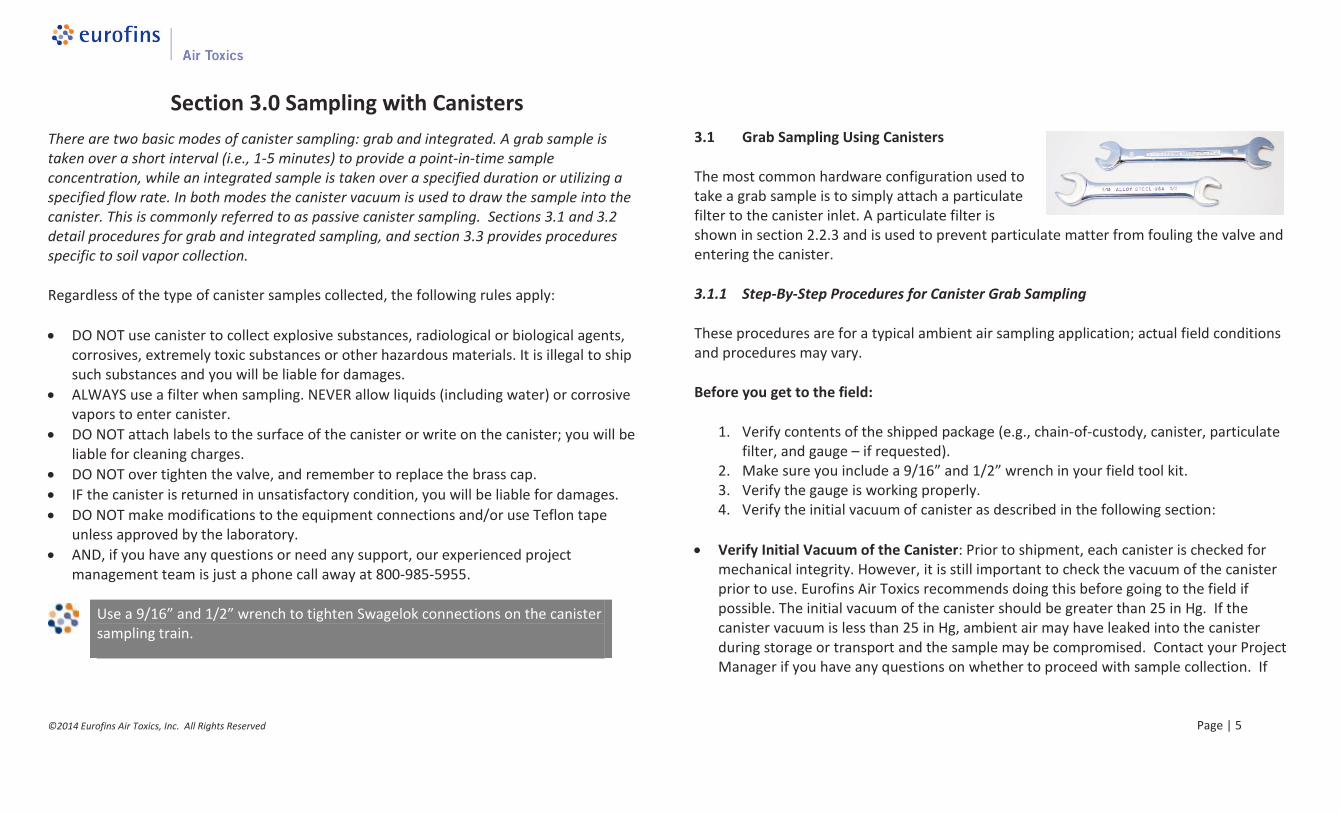
3.1 Grab Sampling Using Canisters
The most common hardware configuration used totake a grab sample is to simply attach a particulatefilter to the canister inlet. A particulate filter isshown in section 2.2.3 and is used to prevent particulate matter from fouling the valve andentering the canister.
3.1.1 Step-By-Step Procedures for Canister Grab Sampling
These procedures are for a typical ambient air sampling application; actual field conditionsand procedures may vary.
Before you get to the field:
1. Verify contents of the shipped package (e.g., chain-of-custody, canister, particulatefilter, and gauge – if requested).
2. Make sure you include a 9/16” and 1/2” wrench in your field tool kit.3. Verify the gauge is working properly.4. Verify the initial vacuum of canister as described in the following section:
Verify Initial Vacuum of the Canister: Prior to shipment, each canister is checked formechanical integrity. However, it is still important to check the vacuum of the canisterprior to use. Eurofins Air Toxics recommends doing this before going to the field ifpossible. The initial vacuum of the canister should be greater than 25 in Hg. If thecanister vacuum is less than 25 in Hg, ambient air may have leaked into the canisterduring storage or transport and the sample may be compromised. Contact your ProjectManager if you have any questions on whether to proceed with sample collection. If
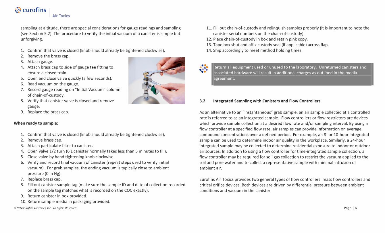
sampling at altitude, there are special considerations for gauge readings and sampling(see Section 5.2). The procedure to verify the initial vacuum of a canister is simple butunforgiving.
1. Confirm that valve is closed (knob should already be tightened clockwise).2. Remove the brass cap.3. Attach gauge.4. Attach brass cap to side of gauge tee fitting to
ensure a closed train.5. Open and close valve quickly (a few seconds).6. Read vacuum on the gauge.7. Record gauge reading on “Initial Vacuum” column
of chain-of-custody.8. Verify that canister valve is closed and remove
gauge.9. Replace the brass cap.
When ready to sample:
1. Confirm that valve is closed (knob should already be tightened clockwise).2. Remove brass cap.3. Attach particulate filter to canister.4. Open valve 1/2 turn (6 L canister normally takes less than 5 minutes to fill).5. Close valve by hand tightening knob clockwise.6. Verify and record final vacuum of canister (repeat steps used to verify initial
vacuum). For grab samples, the ending vacuum is typically close to ambientpressure (0 in Hg).
7. Replace brass cap.8. Fill out canister sample tag (make sure the sample ID and date of collection recorded
on the sample tag matches what is recorded on the COC exactly).9. Return canister in box provided.10. Return sample media in packaging provided.
11. Fill out chain-of-custody and relinquish samples properly (it is important to note thecanister serial numbers on the chain-of-custody).
12. Place chain-of-custody in box and retain pink copy.13. Tape box shut and affix custody seal (if applicable) across flap.14. Ship accordingly to meet method holding times.
Return all equipment used or unused to the laboratory. Unreturned canisters andassociated hardware will result in additional charges as outlined in the mediaagreement.
3.2 Integrated Sampling with Canisters and Flow Controllers
As an alternative to an “instantaneous” grab sample, an air sample collected at a controlledrate is referred to as an integrated sample. Flow controllers or flow restrictors are deviceswhich provide sample collection at a desired flow rate and/or sampling interval. By using aflow controller at a specified flow rate, air samples can provide information on averagecompound concentrations over a defined period. For example, an 8- or 10-hour integratedsample can be used to determine indoor air quality in the workplace. Similarly, a 24-hourintegrated sample may be collected to determine residential exposure to indoor or outdoorair sources. In addition to using a flow controller for time-integrated sample collection, aflow controller may be required for soil gas collection to restrict the vacuum applied to thesoil and pore water and to collect a representative sample with minimal intrusion ofambient air.
Eurofins Air Toxics provides two general types of flow controllers: mass flow controllers andcritical orifice devices. Both devices are driven by differential pressure between ambientconditions and vacuum in the canister.
A mass flow controller employs a diaphragm that activelycompensates to maintain a constant mass flow rate over thedesired time period. As the differential pressure decreases,the flow rate decreases and the diaphragm responds byopening up to allow more air to pass through to maintain a stable flow rate. Mass flowcontrollers are calibrated in the laboratory to provide flow rates suitable for durations up to24 hours. Durations greater than 24 hours are possible, however, performance of the flowcontroller is less reliable due to the low flow rates required.
3.2.2 Critical Orifice Devices
Eurofins Air Toxics has two types of criticalorifice controllers – “capillary column” and“frit pressed”. Both types restrict the flowrate and the canister fill rate decreases asthe canister fills to ambient pressure.These controllers are suitable forapplications not requiring constant flowrate over the sampling period such as soilvapor collection or at sites in which temporal variability of VOCs is not expected. Criticalorifice devices can cover intervals from 0.5 to 12 hours and flow rate from 10 to 250
ml/min. The “capillary column” device (also known as the BlueBody Flow Controller) restricts air flow by forcing the sample toenter a capillary column of minute radius. The flow rate is afunction of the length of inert capillary column. The frit presseddevice has a critical orifice machined to meet a set flow rate.
3.2.3 Sampling Interval and Flow Controller Setting
When you request canisters and flow controllers from Eurofins Air Toxics, you will be askedfor the flow rate (soil vapor) or sampling interval (ambient air), and the flow controllers willbe pre-set prior to shipment. The flow rate is set at standard atmospheric conditions(approximately sea level and 25°C). If samples will be collected at elevation or at ambienttemperatures significantly different than 25°C, the canister will fill faster or slowerdepending on sample conditions. If you specify unusual sample conditions at the time ofproject set-up, we can set the flow controller accordingly. (See Section 5.2 for a discussionof collecting a sample at elevation.) Mass flow controllers should not be utilized for sourceor process samples in which the collection point is under vacuum or pressure. Pleasediscuss these specific non-standard field conditions with your Project Manager at the timeof project set-up.
Table 3.2.3 Flow Rates for Selected Sampling Intervals (mL/min)
Sampling Interval (hrs)4
min. 0.5 1 2 4 8 12 24
6 L Canister NA 167 83.3 41.7 20.8 11.5 7.6 3.8
1 L Canister 167 26.6 13.3 6.7 - - - -
Note: Target fill volumes for 6 L and 1 L canisters are 5,000 mL and 800 mL, respectively.
3.2.4 Final Canister Vacuum and Flow Controller Performance
For time-integrated sample collection using a mass flow controller, the final vacuum of acanister should ideally be approximately 5 in Hg or greater. The flow rate will remainconstant as the canister fills and will start to decrease as the canister vacuum approaches
5 in Hg. At this point, the differential pressure between the canister and ambient air is notsufficient to maintain the set flow rate. Because of normal fluctuations in the flow rate dueto changes in field temperature and pressure, the final vacuum typically ranges between 3and 10 in Hg.
If the residual canister vacuum is greater than 10 in Hg (i.e., more vacuum), the actualflow rate is lower than the set point and less sample volume is collected. When thecanister is pressurized prior to analysis, the pressurization dilution will be greater thannormal. This will result in elevated reporting limits.
If the residual canister vacuum is near ambient pressure for a time-integrated sample,the canister filled faster than calibrated. Once the vacuum decreases below 5 in Hg, theflow rate begins to decrease from its set point. This scenario indicates that the sampleis weighted toward the first portion of the sampling interval. The sampler cannot becertain the desired sampling interval was achieved before the canister arrived atambient conditions. Although the actual sampling interval is uncertain, the canister stillcontains a sample from the site.
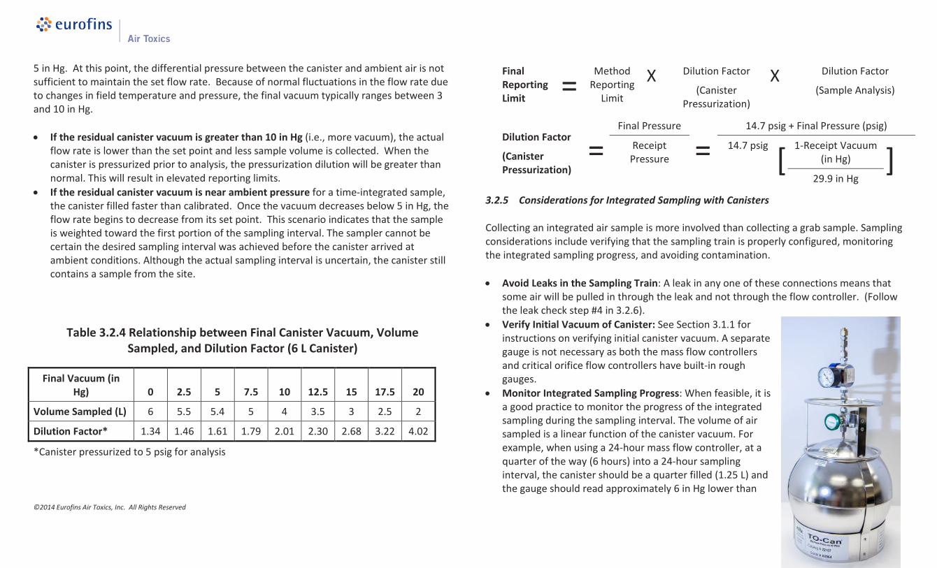
Table 3.2.4 Relationship between Final Canister Vacuum, VolumeSampled, and Dilution Factor (6 L Canister)
3.2.5 Considerations for Integrated Sampling with Canisters
Collecting an integrated air sample is more involved than collecting a grab sample. Samplingconsiderations include verifying that the sampling train is properly configured, monitoringthe integrated sampling progress, and avoiding contamination.
Avoid Leaks in the Sampling Train: A leak in any one of these connections means thatsome air will be pulled in through the leak and not through the flow controller. (Followthe leak check step #4 in 3.2.6).
Verify Initial Vacuum of Canister: See Section 3.1.1 forinstructions on verifying initial canister vacuum. A separategauge is not necessary as both the mass flow controllersand critical orifice flow controllers have built-in roughgauges.
Monitor Integrated Sampling Progress: When feasible, it isa good practice to monitor the progress of the integratedsampling during the sampling interval. The volume of airsampled is a linear function of the canister vacuum. Forexample, when using a 24-hour mass flow controller, at aquarter of the way (6 hours) into a 24-hour samplinginterval, the canister should be a quarter filled (1.25 L) andthe gauge should read approximately 6 in Hg lower than
the starting vacuum (~22 in Hg). More vacuum indicates that the canister is filling tooslowly; less vacuum means the canister is filling too quickly. If the canister is filling tooslowly, a valid sample can still be collected (see Section 3.2.4). If the canister is filling tooquickly because of a leak or incorrect flow controller setting, corrective action can betaken. Ensuring all connections are tight may eliminate a leak. It is possible to take anintermittent sample; the time interval need not be continuous.
Avoid Contamination: Flow controllers should be cleaned between uses. This is done byreturning them to the laboratory.
Caution When Sampling in Extreme Temperatures: Field temperatures can affect theperformance of the mass flow controllers. Laboratory studies have shown that flowrates can increase slightly with decreasing temperatures. A flow rate increase ofapproximately 10% is expected when sampling at field temperatures of 5 to 10°C.
3.2.6 Step-by-Step Procedures for Integrated Sampling
These procedures are for a typical ambient air sampling application; actual field conditionsand procedures may vary.
Before you get to the field:
1. Verify contents of the shipped package (e.g., chain-of-custody, canister, and flowcontroller)
2. Make sure you include a 9/16” and 1/2” wrench in your field tool kit.3. Verify the gauge is working properly4. Verify the initial vacuum of canister (section 3.1.1)
When ready to sample:
1. Confirm that valve is closed (knob should already be tightened clockwise).2. Remove brass cap from canister.
3. Attach flow controller to canister. The flow controller is securely attached if the flowcontroller body does not rotate.
4. Place the brass cap at the end of the flow controller creating an air tight train, andquickly open and close the canister valve in order to check for leaks. If the needle on thegauge drops, your train is not airtight. In this case, try refitting your connections and/ortightening them until the needle holds steady.
5. Once the sample train is airtight remove the brass cap from the flow controller andopen the canister valve a ½ turn.
6. Monitor integrated sampling progress periodically.7. Verify and record final vacuum of canister (simply read built-in gauge).8. When sampling is complete, close valve by hand tightening knob clockwise.9. Detach flow controller and replace brass cap on canister.10. Fill out canister sample tag (make sure the sample ID and date of collection recorded on
the sample tag matches what is recorded on the COC exactly).11. Return canisters and associated media in boxes provided. Failure to return all of the
provided equipment will result in a replacement charge as outlined in the mediaagreement.
12. Fill out chain-of-custody and relinquish samples properly (it is important to note thecanister serial numbers on the chain-of-custody).
13. Place chain-of-custody in box and retain pink copy.14. Tape box shut and affix custody seal at each opening (if applicable).15. Ship accordingly to meet method holding times.
3.3 Soil Gas Sample Collection
Canisters can be used for the collection of soil vapor by attaching the sampling train to thesoil gas probe. Typically, a critical orifice flow controller is used to minimize the appliedvacuum in order to minimize partitioning of VOCs from the soil or pore water to the soilvapor. Additionally, lower flow rates help to minimize the intrusion of ambient air into thesoil vapor probe. In general, time-integration is not required for soil gas samples; however,there may be exceptions to this rule of thumb. For example, some regulatory guidancedocuments recommend concurrent indoor air and sub-slab soil vapor collection over a
24-hour period. This means that a mass flow controller calibrated for a 24-hour samplewould be required for the sub-slab as well as the indoor air sample.
3.3.1 Canister to probe connection – Tubing
Collection of a soil gas sample requires the use of tubing to connect the soil gas probe to thesample train. Teflon FEP tubing is recommended based on its low background and itsinertness. Alternative tubing can be used if shown to meet data quality objectives. Pleasenote that Low Density Polyethylene or flexible Tygon tubing is not recommended due toVOC adsorption during sample collection. Teflon tubing is provided by the laboratory uponrequest at the time of order. A charge based on the length will be assessed. It is importantto store the tubing away from VOC sources during storage and transport to the site tominimize contamination.
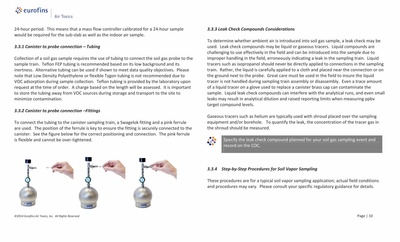
3.3.2 Canister to probe connection –Fittings
To connect the tubing to the canister sampling train, a Swagelok fitting and a pink ferruleare used. The position of the ferrule is key to ensure the fitting is securely connected to thecanister. See the figure below for the correct positioning and connection. The pink ferruleis flexible and cannot be over-tightened.
3.3.3 Leak Check Compounds Considerations
To determine whether ambient air is introduced into soil gas sample, a leak check may beused. Leak check compounds may be liquid or gaseous tracers. Liquid compounds arechallenging to use effectively in the field and can be introduced into the sample due toimproper handling in the field, erroneously indicating a leak in the sampling train. Liquidtracers such as isopropanol should never be directly applied to connections in the samplingtrain. Rather, the liquid is carefully applied to a cloth and placed near the connection or onthe ground next to the probe. Great care must be used in the field to insure the liquidtracer is not handled during sampling train assembly or disassembly. Even a trace amountof a liquid tracer on a glove used to replace a canister brass cap can contaminate thesample. Liquid leak check compounds can interfere with the analytical runs, and even smallleaks may result in analytical dilution and raised reporting limits when measuring ppbvtarget compound levels.
Gaseous tracers such as helium are typically used with shroud placed over the samplingequipment and/or borehole. To quantify the leak, the concentration of the tracer gas inthe shroud should be measured.
Specify the leak check compound planned for your soil gas sampling event andrecord on the COC.
3.3.4 Step-by-Step Procedures for Soil Vapor Sampling
These procedures are for a typical soil vapor sampling application; actual field conditionsand procedures may vary. Please consult your specific regulatory guidance for details.
1. Verify contents of the shipped package (e.g., chain-of-custody, canister, tubing, fittings,and flow controller).
2. Make sure you include a 9/16” and 1/2” wrench in your field tool kit.3. Verify the gauge is working properly.4. Verify the initial vacuum of canister.
Prior to vapor collection:
Purge tubing adequately. A long length of tubing has significant volume of “dead air”inside. Without purging, this air will enter the canister and dilute the sample. Considerusing a handheld PID/FID to confirm that you have purged the tubing and are drawingsample air through the tubing. A standard rule of thumb is to utilize 3 purge volumesprior to sample collection. However, under certain circumstances, purge volumes of 1to 10 may be appropriate. Please review your regulatory guidance and your site specificconditions in determining the appropriate purge volumes.
Don’t sample water. If moisture is visible in the sample tubing, the soil gas sample maybe compromised. Soil gas probes should be at an appropriate depth to avoid reachingthe water table. Additionally, subsurface vapor should not be collected immediatelyafter measurable precipitation.
When ready to sample:
1. Confirm that valve is closed (knob should already be tightened clockwise).2. Remove brass cap from canister.3. Attach flow controller to canister if needed. The flow controller is securely attached if
the flow controller body does not rotate. (Note: The frit-press flow controller and 1 Lcanister may be pre-assembled by the laboratory.)
4. Place the brass cap at the end of the flow controller creating an air tight train, andquickly open and close the canister valve in order to check for leaks. If the needle on the
gauge drops, your train is not airtight. In this case, try refitting your connections and/ortightening them until the needle holds steady.
5. Once the sample train is airtight remove the brass cap from the flow controller andattach the probe tubing to the flow controller using the pink ferrule and Swagelok nut.(See 3.3.2 for proper positioning of the ferrule.)
6. Once the probe line has been purged and appropriate leak check measures have beenimplemented, open the canister valve a ½ turn.
7. Verify and record final vacuum of canister (simply read built-in gauge).8. When canister fills to the desired end vacuum, close valve by hand tightening knob
clockwise.
Please note: Some projects require residual vacuum of approximately 5 in Hg at the endof sample collection even if time-integrated samples are not required. The residualvacuum serves to provide a check of the integrity of the canister during transport to thelaboratory to insure no leaks occurred during shipment. A field vacuum reading similarto the lab receipt vacuum reading demonstrated that no leak occurred.
9. Detach tubing and flow controller and replace brass cap on the canister.10. Fill out canister sample tag (make sure the sample ID and date of collection recorded on
the sample tag matches what is recorded on the COC exactly).11. Return canisters and associated media in boxes provided. Failure to return all of the
provided equipment will result in a replacement charge as outlined in the mediaagreement.
12. Fill out chain-of-custody and relinquish samples properly (it is important to note thecanister serial numbers on the chain-of-custody).
13. Place chain-of-custody in box and retain pink copy14. Tape box shut and affix custody seal at each opening (if applicable)15. Ship accordingly to meet method holding times
3.4.4 Collecting Soil Gas Samples with Sampling Manifolds
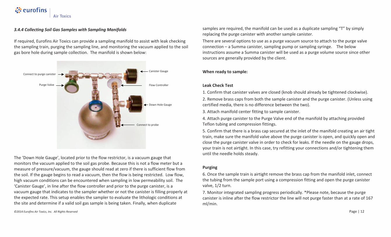
If required, Eurofins Air Toxics can provide a sampling manifold to assist with leak checkingthe sampling train, purging the sampling line, and monitoring the vacuum applied to the soilgas bore hole during sample collection. The manifold is shown below:
The ‘Down Hole Gauge’, located prior to the flow restrictor, is a vacuum gauge thatmonitors the vacuum applied to the soil gas probe. Because this is not a flow meter but ameasure of pressure/vacuum, the gauge should read at zero if there is sufficient flow fromthe soil. If the gauge begins to read a vacuum, then the flow is being restricted. Low flow,high vacuum conditions can be encountered when sampling in low permeability soil. The‘Canister Gauge’, in line after the flow controller and prior to the purge canister, is avacuum gauge that indicates to the sampler whether or not the canister is filling properly atthe expected rate. This setup enables the sampler to evaluate the lithologic conditions atthe site and determine if a valid soil gas sample is being taken. Finally, when duplicate
samples are required, the manifold can be used as a duplicate sampling “T” by simplyreplacing the purge canister with another sample canister.
There are several options to use as a purge vacuum source to attach to the purge valveconnection – a Summa canister, sampling pump or sampling syringe. The belowinstructions assume a Summa canister will be used as a purge volume source since othersources are generally provided by the client.
When ready to sample:
Leak Check Test
1. Confirm that canister valves are closed (knob should already be tightened clockwise).
2. Remove brass caps from both the sample canister and the purge canister. (Unless usingcertified media, there is no difference between the two).
3. Attach manifold center fitting to sample canister.
4. Attach purge canister to the Purge Valve end of the manifold by attaching providedTeflon tubing and compression fittings.
5. Confirm that there is a brass cap secured at the inlet of the manifold creating an air tighttrain, make sure the manifold valve above the purge canister is open, and quickly open andclose the purge canister valve in order to check for leaks. If the needle on the gauge drops,your train is not airtight. In this case, try refitting your connections and/or tightening themuntil the needle holds steady.
Purging
6. Once the sample train is airtight remove the brass cap from the manifold inlet, connectthe tubing from the sample port using a compression fitting and open the purge canistervalve, 1/2 turn.
7. Monitor integrated sampling progress periodically. *Please note, because the purgecanister is inline after the flow restrictor the line will not purge faster than at a rate of 167ml/min.
8. Once the desired purge volume is met close both the manifold valve and the purgecanister valve by hand tightening the knobs clockwise.
9. If sampling at multiple locations, the purge canister can be disconnected from themanifold and used to begin purging the next sample location without compromising thesample train.
Sampling
10. The line is now ready to be sampled. Open the sample canister valve and monitorsampling progress periodically.
11. When the sampling is complete close the valve and replace the brass cap on thecanister; record final vacuum of canister (simply read built-in gauge).
12. Fill out canister sample tag (make sure the sample ID and date of collection recorded onthe sample tag matches what is recorded on the COC exactly).
13. Return canisters in boxes provided and all parts of the soil gas manifold. Unreturnedmedia will result in a replacement charged assessed as described in the media agreement.
14. Fill out chain-of-custody and relinquish samples properly (it is important to note thecanister serial numbers on the chain-of-custody).
15. Place chain-of-custody in box and retain pink copy.
16. Ship accordingly to meet method holding times.
This section provides a description of the types of air sampling bags, selecting the right bagfor your application, practical considerations for sampling, and step-by-step instructions forcollecting a grab sample. Photographs illustrate the correct way to assemble the varioussampling components.
4.1 Introduction to Bags
Air sampling bags are containers used to collect whole air samples for landfill gas, soil gasand stationary source applications. Bags can be constructed from various materials whichcan differ in terms of stability characteristics and cleanliness. In general, air sampling bagsare best suited for projects involving analysis of compounds in the ppmv range. They can beused to collect sulfur compounds, but only if the fittings are non-metallic (e.g.,polypropylene, Teflon®, or Nylon).
Air sampling bags are equipped with a valve that allows for filling. Sample collectionrequires a pressurized sampling port, a low flow rate pump or a lung sampler. The bagexpands as the vapor sample is pulled in. When the target volume of the sample iscollected, the valve is closed and the bag is returned to the laboratory. Bag materials shouldbe selected based on the specific application. Common air sampling bags include Tedlarfilm and FlexFoil. Eurofins Air Toxics maintains a limited inventory of air sampling bags in 1L, 3 L and 5 L volumes.
4.1.1 Tedlar®Film
Tedlar® is a trade name for a polyvinyl fluoride film developed by DuPont Corporation in the1960’s. This patented fluoropolymer has been used in a wide variety of applicationsincluding protective surfacing for signs, exterior wall panels and aircraft interiors. Tedlar®film is tough yet flexible and retains its impressive mechanical properties over a wide range
of temperatures (from well below freezing to over 200°F). Tedlar® exhibits low permeabilityto gases, good chemical inertness, good weathering resistance and low off-gassing.
Tedlar® bags may be used to collect samples containingcommon solvents, hydrocarbons, chlorinated solvents,sulfur compounds, atmospheric and biogenic gases andmany other classes of compounds. Compounds with lowvapor pressures such as Naphthalene are not appropriatefor Tedlar bags as recovery is very low even under shortsample storage times. Low molecular compounds such asHelium and Hydrogen can diffuse through the Tedlar bagmaterial resulting in poor storage stability.
4.1.2 Tedlar® Bag Suppliers and Re-use
Compounds commonly detected from analyzing new Tedlar® bags include methylenechloride, toluene, acetone, ethanol, 2-propanol, phenol, and dimethylacetamide. Whilelevels of these common artifacts are typically in the ppbv range, the cleanliness of bags canvary significantly between vendors, and purchasing bags directly from an unknown vendorshould be avoided. Once the Tedlar® bag is used for sample collection, the surface has beenexposed to moisture and possible VOCs. It may irreversibly adsorb many VOCs at the lowppbv level. A series of purges with certified gas may not remove the VOCs from the surface.Consider your data quality objectives to determine whether re-using Tedlar® bags isappropriate.
4.1.3 Hold Time for a Tedlar® Bag
The media hold time for a Tedlar® bag is indefinite if stored out of sunlight in a cool, drylocation.
The sample hold time to analysis varies by method and compound. See Table 4.1.3 forrecommended sample storage times for commonly requested parameters.
Table 4.1.3 Recommended Maximum Sample Storage Times for Tedlar® Bags
Analytical Method Chemical Class Storage Time
ASTM D5504 Suite of sulfur compounds includingReactive Sulfur compounds (Hydrogensulfide, Methyl mercaptan)
24 hours
ASTM D1946
ASTM D1945
Atmospheric and natural gases:
CO, CO2, CH4, C2-C5 hydrocarbons
(He and H2 not recommended)
Up to 3 days
Modified TO-14A, TO-15,
TO-3, TO-12
Volatile Organic Compounds (VOCs) Up to 3 days
4.1.4 FlexFoil Bags
FlexFoil bags are made from an opaque and flexible material with 4-ply constructionresulting in high physical strength to minimize rupture and leakage and low permeability toprovide good stability for low molecular weight compounds. FlexFoil bags are ideal fortarget compounds such as Hydrogen and Helium and can be used for the suite ofatmospheric and natural gas components. While the reactive sulfur compounds, HydrogenSulfide and Methyl Mercaptan, show good stability over 24 hours in FlexFoil bags, othersulfur compounds demonstrate low recovery. Table 4.1.4 summarizes the compounds andthe hold times amenable to FlexFoil bags.
Table 4.1.4 Recommended Maximum Sample Storage Times for FlexFoil Bags
Analytical Method Chemical Class Storage Time
ASTM D5504 Hydrogen sulfide, Methyl mercaptan only
Not recommended for full sulfur list.
24 hours
ASTM D1946
ASTM D1945
Atmospheric and natural gases
Full List
Up to 3 days
4.2 Air Bag Sampling
Using a bag to collect an air sample normally involves “active” sampling, unlike anevacuated canister that can be filled “passively” by simply opening the valve. There are twomethods commonly used to fill a bag: a pump or a lung sampler.
Sampling with a Pump: The most commonmethod for filling a bag is to use a smallpump with low flow rates (50-200 mL/min)and tubing to fill the bag. Eurofins AirToxics, Inc. does not provide pumps butpumps may be rented from equipmentproviders or purchased frommanufacturers such as SKC or Gilian.
Sampling with a Lung Sampler: A “lungsampler” may be used to fill a bag.Although a little more complicated thansimply using a pump, the main advantageto using a lung sampler to fill a bag is that itavoids potential pump contamination.
A bag with attached tubing is placed in a small airtight chamber (even a 5-gallon bucketcan work) with the tubing protruding from the chamber. The sealed chamber is thenevacuated via a pump, causing the bag to expand and draw the sample into the bagthrough the protruding tube. The sample air never touches the wetted surfaces of thepump. Eurofins Air Toxics does not provide lung samplers, but they can be rented fromequipment suppliers or purchased by manufacturers such as SKC Inc.
4.2.1 Considerations for Bag Sampling
Some considerations for collecting a bag sample:
Fill the bag no more than 2/3 full: Allow for possible expansion due to an increase intemperature or decrease in atmospheric pressure (e.g., the cargo hold of a plane)
Keep the Tedlar® bag out of sunlight: Tedlar® film is transparent to ultraviolet light(although opaque versions are available) and the sample should be kept out of sunlightto avoid any photochemical reactions
Protect the bag: Store and ship the bag samples in a protective box at roomtemperature. An ice chest may be used, but DO NOT CHILL
Fill out the bag label: It is much easier to write the sample information on the labelbefore the bag is inflated. Make sure to use a ball-point pen, never a Sharpee or othermarker which can emit VOCs.
Provide a “back-up” bag: Consider filling two bags per location in the rare occasion thata defective bag deflates before analysis. The “hold” sample does not need to bedocumented on the Chain-of-Custody and should have an identical sample ID to theoriginal sample indicating that it is the “hold” sample
Avoid Contamination: Care should be taken to avoid contamination introduced by thepump or tubing. Begin sampling at locations with the lowest compound concentrations(e.g., sample the SVE effluent before the influent). Decontaminate the pump betweenuses by purging with certified air for an extended period; better yet, use a lung sampler.Use the shortest length possible of Teflon® tubing or other inert tubing. DO NOT REUSETUBING. If long lengths of tubing are used, consider purging the tubing with several
volumes worth before sampling. If you are concerned about sampling for tracecompounds, you shouldn’t be using a Tedlar® bag (see Section 1.2)
Don’t Sample Dangerous Compounds in a Bag: Do not ship any explosive substances,radiological or biological agents, corrosives or extremely hazardous materials to EurofinsAir Toxics. Bag rupture during transit to the laboratory is possible and the samplerassumes full liability.
4.2.2 Step-by-Step Procedures for Bag Sampling (Pump)
Note: These procedures are for a typical stationary source (e.g., SVE system) samplingapplication; actual field conditions and procedures may vary.
Before you get to the field:
1. Verify contents of the shipped package (e.g., chain-of-custody, bag, and tubing/fittings –if requested).
2. Verify pump cleanliness and operation (Eurofins Air Toxics does not provide pumps).
When ready to sample:
3. Purge sample port.4. Attach new Teflon® tubing from sample port or probe to low flow rate pump.5. Purge tubing.6. Fill out bag sample tag.7. Attach additional new Teflon® tubing from the pump outlet to the bag valve.8. Open bag valve.9. Collect sample (FILL NO MORE THAN 2/3 FULL).10. Close bag valve by hand tightening valve clockwise.11. Return filled bags in a rigid shipping container (DO NOT CHILL).12. Fill out chain-of-custody and relinquish samples properly.13. Place chain-of-custody in box and retain pink copy.
14. Tape box shut and affix custody seal (if applicable) across flap.15. Ship first overnight or priority overnight to meet method holding times.
Expedite delivery of air sampling bags to the laboratory for analysis.
Section 5.0 Special Sampling Considerations
This section provides recommendations for the collection of field QC samples such as fieldduplicates. Considerations for sampling at altitude, sampling SVE ports and using samplecylinders are presented.
5.1 Field QC
To measure accuracy and precision of the field activities, project plans often include fieldduplicates, field blanks, ambient blanks, trip blanks and/or equipment blanks.
5.1.1 Field Duplicate
A field duplicate is a second sample collected in the field simultaneously with the primarysample at one sampling location. The results of the duplicate sample may be compared(e.g., calculate relative percent difference) with the primary sample to provide informationon consistency and reproducibility of field sampling procedures. Due to the nature of thegas phase, duplicate samples should be collected from a common inlet. The configurationfor collecting a field duplicate includes stainless steel or Teflon® tubing connected to aSwagelok “T”. If integrated samples are being collected and the sample duration is to bemaintained, the sample train should be assembled as follows: each canister should have aflow controller attached, then the duplicate sampling T should be attached to the flowcontrollers. If the collection flow rate from the sample port is to be maintained then the
duplicate sampling T should be connected to the canisters; then the flow controller isconnected to the inlet of the sampling T.
Alternatively, if the project objective is to assess spatial or temporal variability, then fieldduplicates may be deployed in close proximity (ambient air sampling) or samples may becollected in succession (soil vapor).
5.1.2 Field Blank
A field blank is a sample collected in the field from a certified air source. Analysis of the fieldblank can provide information on the decontamination procedures used in the field. Cleanstainless steel or Teflon® tubing and a certified regulator should be used. It is imperativethat individually certified canisters (the sample canister and the source canister/cylinder, ifapplicable) be used to collect a field blank.
5.1.3 Ambient Blank
An ambient blank is an ambient air sample collected in the field. It is usually used inconjunction with soil gas or stationary source (e.g., SVE system) sampling. Analysis of theambient blank can provide information on the ambient levels of site contaminants. It isrecommended that an individually certified canister be used to collect an ambient blank.
5.1.4 Trip Blank
When sampling for contaminants in water, the laboratory prepares a trip blank by filling aVOA vial with clean, de-ionized water. The trip blank is sent to the field in a cooler with newsample vials. After sampling, the filled sample vials are placed back in the cooler next to thetrip blank and returned to the laboratory. Analysis of the trip blank provides information ondecontamination and sample handling procedures in the field as well as the cleanliness ofthe cooler and packaging.
When sampling for compounds in air, a trip blank provides little, if any, of the informationabove. A trip blank canister can be individually certified, evacuated, and sent to the field ina box with the sample canisters. Since the valve is closed and the brass cap tightened, it isquestionable if the trip blank canister contents are ever “exposed” to sampling conditions.The trip blank VOC concentrations essentially provide information regarding the cleanlinessand performance of the trip blank canister. Results cannot necessarily be applied to theassociated field sample canisters accompanying the trip blank. Eurofins Air Toxics does notrecommend collecting a trip blank for air sampling.
5.2 Considerations for Sampling at Altitude
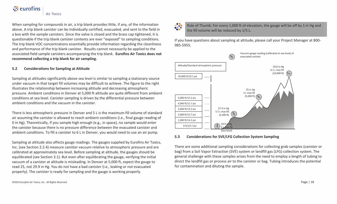
Sampling at altitudes significantly above sea level is similar to sampling a stationary sourceunder vacuum in that target fill volumes may be difficult to achieve. The figure to the rightillustrates the relationship between increasing altitude and decreasing atmosphericpressure. Ambient conditions in Denver at 5,000 ft altitude are quite different from ambientconditions at sea level. Canister sampling is driven by the differential pressure betweenambient conditions and the vacuum in the canister.
There is less atmospheric pressure in Denver and 5 L is the maximum fill volume of standardair assuming the canister is allowed to reach ambient conditions (i.e., final gauge reading of0 in Hg). Theoretically, if you sample high enough (e.g., in space), no sample would enterthe canister because there is no pressure difference between the evacuated canister andambient conditions. To fill a canister to 6 L in Denver, you would need to use an air pump.
Sampling at altitude also affects gauge readings. The gauges supplied by Eurofins Air Toxics,Inc. (see Section 2.2.4) measure canister vacuum relative to atmospheric pressure and arecalibrated at approximately sea level. Before sampling at altitude, the gauges should beequilibrated (see Section 3.1). But even after equilibrating the gauge, verifying the initialvacuum of a canister at altitude is misleading. In Denver at 5,000 ft, expect the gauge toread 25, not 29.9 in Hg. You do not have a bad canister (i.e., leaking or not evacuatedproperly). The canister is ready for sampling and the gauge is working properly.
Rule of Thumb: For every 1,000 ft of elevation, the gauge will be off by 1 in Hg andthe fill volume will be reduced by 1/5 L.
If you have questions about sampling at altitude, please call your Project Manager at 800-985-5955.
5.3 Considerations for SVE/LFG Collection System Sampling
There are some additional sampling considerations for collecting grab samples (canister orbag) from a Soil Vapor Extraction (SVE) system or landfill gas (LFG) collection system. Thegeneral challenge with these samples arises from the need to employ a length of tubing todirect the landfill gas or process air to the canister or bag. Tubing introduces the potentialfor contamination and diluting the sample.
10,000 ft/10.1 psi
5,000 ft/12.2 psi
4,000 ft/12.7 psi
3,000 ft/13.2 psi
2,000 ft/13.7 psi
1,000 ft/14.2 psi
0 ft/14.7 psi
Altitude/Standard atmospheric pressure
Vacuum gauge reading (calibrated at sea level) ofevacuated canister
Use inert tubing. Teflon® tubing is recommended. Tubing with an outer diameter of ¼”works best with the fittings on the particulate filter. (See Section 3.3.1).
Do not reuse tubing.
Purge tubing adequately. A long length of tubing has significant volume of “dead air”inside. Without purging, this air will enter the canister and dilute the sample. Considerusing a handheld PID/FID to confirm that you have purged the tubing and are drawingsample air through the tubing.
Avoid leaks in the sampling train. Leaks of ambient air through fittings between piecesof the sampling train (e.g., tubing to particulate filter) will dilute the sample.
Always use compression fittings for all connections; never use tube in tube connections.
Purge the sample port. A sample port on an SVE system or LFG collection system canaccumulate solids or liquids depending upon the location of the port in the process andthe orientation of the port. An influent sample port located upstream of a filter ormoisture knock-out can be laden with particulates or saturated with water vapor. Heavyparticulate matter can clog the particulate filter and foul the canister valve. It isimportant to prevent liquids from entering the canister. A sample port orienteddownward may have liquid standing in the valve. Purge the sample port adequatelybefore connecting the sampling train.
Consider the effects of sampling a process under vacuum or pressure. When collectinga grab sample from a stationary source such as an SVE system or LFG collection system,some sample ports may be under vacuum or pressure relative to ambient conditions.When the sample port is under vacuum, such as the header pipe from the extractionwell network, it may be difficult to fill the canister with the desired volume of sample. Avacuum pump may be used to collect a canister grab sample from a sample port underconsiderable vacuum. See the related discussion on sampling at altitude in Section 5.2.When the sample port is under pressure, such as the effluent stack downstream of theblower and treatment system, you may inadvertently pressurize the canister. Only aDOT-approved sample cylinder should be used to transport pressurized air samples (seeSection 5.4). Under no circumstances should a Summa canister be pressurized morethan 15 psig. Bleed off excess pressure by opening the valve temporarily whilemonitoring the canister with a pressure gauge.
5.4 Considerations for Sample Cylinder Sampling
Sample cylinders, also known as “sample bombs”, are DOT-approved, high pressure, thick-walled, stainless steel cylinders with a valve at each end. They were intended for collectinga pressurized sample for petroleum gas applications. Sample cylinders differ from samplecanisters in that they do not have a Summa-passivated interior surface and are notevacuated prior to shipment. Sample cylinders are not suitable for analysis of hydrocarbonsat ppbv levels. Sample cylinders can be used for analysis of natural gas by ASTM D-1945 andcalculation of BTU by ASTM D-3588. Eurofins Air Toxics assumes that clients requesting asample cylinder have a pressurized process and sample port with a built-in gauge and 1/4“Swagelok fitting to attach to the sample cylinder. Eurofins Air Toxics has a limited inventoryof 500 mL sample cylinders that are particularly suited for landfill gas collection systems(i.e., LFG to energy applications). This section provides step-by-step procedures for samplingwith a sample cylinder.
Inform the lab during project set up if hazardous samples (e.g. high Hydrogen Sulfideconcentrations) will be collected to verify the lab can safely handle the samples.
Step-by-Step Procedures for Sample Cylinder Sampling
These procedures are for a typical stationary source sampling application and actual fieldconditions; procedures may vary. Follow all precautions in the site Health and Safety Planwhen dealing with a pressurized sample port and sample cylinder. Follow required DOTguidelines for packaging and shipping.
1. Verify contents of the shipped package (e.g., chain-of-custody, sample cylinder,particulate filter).
2. Verify that gauge on sample port is working properly.3. Purge sample port.
4. Remove brass caps on either end of cylinder.5. Attach particulate filter to upstream valve.6. Attach filter/cylinder assembly directly to the sample port.7. Open both valves 1/2 turn.8. Allow sample air to flow through sample cylinder (approximately 10 L for a 500 mL
cylinder).9. Close downstream valve of sample cylinder by hand tightening knob clockwise.10. Allow sample cylinder to pressurize to process pressure (max 100 psig).11. Close upstream valve of sample cylinder and sample port.12. Detach filter/cylinder assembly from sample port and remove particulate filter.13. Replace brass caps.14. Fill out sample cylinder sample tag.15. Fill out chain-of-custody and relinquish samples properly.16. Include the chain-of-custody with the samples and retain pink copy.17. Pack, label, and ship according to DOT regulations.
Follow DOT regulations for packaging and shipping hazardous samples.
Eurofins Air Toxics, Inc.180 Blue Ravine Road, Suite B | Folsom, CA 95630
Tel | 1-800-985-5955 | Fax | 916-985-1020www.AirToxics.com