66
of Asphalt Parking Lots Guide to CONCRETE OVERLAYS October 2012

of Asphalt Parking Lots
Guide to
CONCRETEOVERLAYS
October 2012


Guide to Concrete Overlays of Asphalt Parking Lots i
Technical Report Documentation Page
1. Report No. 2. Government Accession No. 3. Recipient’s Catalog No.
4. Title and Subtitle 5. Report Date Guide to Concrete Overlays of Asphalt Parking Lots October 2012
6. Performing Organization Code
7. Author(s) 8. Performing Organization Report No.Dale S. Harrington and Randell C. Riley
9. Performing Organization Name and Address 10. Work Unit No. (TRAIS) National Concrete Pavement Technology Center Iowa State University 2711 South Loop Drive, Suite 4700 Ames, IA 50010‐8664
11. Contract or Grant No.
12. Sponsoring Organization Name and Address 13. Type of Report and Period CoveredReady Mixed Concrete Research & Education Foundation 900 Spring Street Silver Spring, MD 20910
Manual
14. Sponsoring Agency Code
15. Supplementary Notes
16. Abstract
The purpose of the Guide to Concrete Overlays of Asphalt Parking Lots is to provide information for decision makers and practitioners about selecting, designing, and constructing successful concrete overlays on existing asphalt parking lot pavements that serve multifamily residential, public, or commercial buildings. It focuses on parking areas that carry and store light vehicles (primarily automobiles and pickup trucks), but it also addresses adjacent access roads and truck lanes that regularly carry heavy trucks for the delivery and pickup of goods and materials, including solid waste containers. It offers expert guidance to supplement practitioners’ own professional experience and judgment. With this information, parking lot owners can confidently include concrete overlays in their toolbox of asphalt parking lot solutions and make informed decisions about overlay design and construction based on existing asphalt conditions.
This guide is a companion document to the Guide to Concrete Overlays: Sustainable Solutions for Resurfacing and Rehabilitating Existing Pavements, Second Edition, and the Guide to the Design of Concrete Overlays Using Existing Methodologies.
17. Key Words 18. Distribution Statement Concrete overlays — parking lot pavements —parking lot overlays Available through National Ready Mixed
Concrete Association
19. Security Classification (of this report)
20. Security Classification (of this page)
21. No. of Pages 22. Price
Unclassified. Unclassified. 62 (including front matter)
Form DOT F 1700.7 (8‐72) Reproduction of completed page authorized

ii Guide to Concrete Overlays of Asphalt Parking Lots

Guide to Concrete Overlays of Asphalt Parking Lots iii
October 2012
CONCRETE OVERLAYS OF ASPHALT PARKING LOTS
GUIDE TO
AuthorsDale S. Harrington, Snyder & Associates, Inc.Randell C. Riley, Illinois Chapter, American Concrete Pavement Association
Contributing AuthorsJ. Dewayne Allen, Allen Engineering CorporationAmanda Bordelon, University of UtahJerry Holland, Structural Services, Inc.Nigel Parkes, PNA Construction Technologies, Inc.
Technical ReviewersDan DeGraaf, Michigan Concrete AssociationJeffery R. Roesler, University of IllinoisJulie M. Vandenbossche, University of Pittsburgh
Technical CalculationsJerod Gross, Snyder & Associates, Inc.
Project CoordinatorMelisse Leopold, Snyder & Associates, Inc.
Technical ResearcherLorraine Burke, Snyder & Associates, Inc.
Editor and LayoutMarcia Brink, National Concrete Pavement Technology Center
Cover DesignerWendy Stribe, National Concrete Pavement Technology Center
iv Guide to Concrete Overlays of Asphalt Parking Lots
Acknowledgments Development of this guide has truly been a collaborative effort. The authors and the National Concrete Pavement Technology Center (National CP Tech Center) gratefully acknowledge the support and working partnership of the National Ready Mixed Concrete Association (NRMCA) in bringing the guide from concept to reality. Funding was provided by the Ready Mixed Concrete Research & Education Foundation, with technical assistance provided by the NRMCA.
In addition, we sincerely appreciate the invaluable contributions of an extensive technical advisory committee representing public and private stakeholders from across the country. Its members helped establish the technical direction of this guide, provided insightful responses to many drafts, and helped shape the con-tent of several specific sections. Many thanks to every committee member:
J. Dewayne Allen, Allen Engineering CorporationBryan Birdwell, Birdwell & Associates, LLCDavid Buzzelli, MCM Commercial Concrete, Inc.Tom Cackler, National CP Tech Center John Cunningham, Iowa Concrete Paving Association
Norbert Delatte, Cleveland State UniversitySybil Ferrier, Construction Materials TestingJon Hansen, NRMCAJerry Holland, Structural Services, Inc.Nigel Parkes, PNA Construction Technologies, Inc.Randell C. Riley, Illinois Chapter, American Concrete
Pavement Association (ACPA)Gordon Smith, Iowa Concrete Paving Association David Suchorski, Ash Grove Cement Len Swederski, Swederski Concrete Construction, Inc.Lori Tiefenthaler, Lehigh Hanson
Finally, and in particular, the authors heartily thank committee members Jon Hansen and Gordon Smith. From day one of this project, Jon and Gordon were enthusiastic “go-to” resources and sounding boards, ready to help at a moment’s notice. Thank you for never failing to pick up the phone or respond to an email.
Photo and Illustration CreditsExcept for those credited to other sources herein, the photo-graphs reproduced in this document were provided by the following people:
J. Dewayne Allen, Allen Engineering Corporation Bryan Birdwell, Birdwell & Associates, LLCJon Hansen, NRMCA Randell C. Riley, Illinois Chapter, ACPA
Figures 19, 21, and 25–36 were provided by Snyder & Associates, Inc.
For More InformationTom Cackler, DirectorMarcia Brink, Managing EditorNational Concrete Pavement Technology CenterIowa State University Research Park2711 S. Loop Drive, Suite 4700Ames, IA 50010-8664515-294-9480, www.cptechcenter.org/[email protected]
DisclaimersNeither Iowa State University nor this document’s authors, editors, designers, illustrators, distributors, or technical advisors make any representations or warranties, expressed or implied, as to the accuracy of information herein and disclaim liability for any inaccuracies.
Iowa State University does not discriminate on the basis of race, color, age, religion, national origin, sexual orientation, gender identity, sex, marital status, disability, genetic testing, or status as a U.S. veteran. Inquiries can be directed to the Director of Equal Opportunity and Diversity, Iowa State University, 3680 Beardshear Hall, 515-294-7612.
MissionThe mission of the National Concrete Pavement Technology Center is to unite key transportation stakeholders around the central goal of advanc-ing concrete pavement technology through research, technology transfer, and technology implementation.

Guide to Concrete Overlays of Asphalt Parking Lots v
ContentsAcknowledgments ......................................................iv
Photo and Illustration Credits .....................................iv
List of Figures ...............................................................vi
List of Tables ..............................................................viii
About This Guide ........................................................ix
Introduction ...................................................................1
Overview of Concrete Overlay Characteristics ...........2
Considerations Unique to Parking Lot Overlays ........3
Parking lot elevation .......................................................3
Traffic ...............................................................................3
Changes in lot use ...........................................................4
Assessing Existing Pavement Condition ....................4
Historical records review, data collection, and future projections ...........................4
Pavement and site conditions and considerations ......6
Visual inspection .............................................................6
Core analyses ..................................................................7
Optional analysis of support conditions ........................8
Pavement Evaluation Report ..........................................8
Identifying Pavement Distresses and Levels of Severity ...................................................9
Types of distress ............................................................ 10
Severity of distress ....................................................... 10
Alligator cracking .................................................... 11
Block cracking .........................................................12
Potholes, popouts ..................................................13
Raveling ..................................................................14
Thermal cracking ....................................................15
Random cracking ....................................................16
Access or truck lane rutting ...................................17
Access or truck lane shoving (slippage) ...............18
Concrete Overlay Design .......................................... 19
Overlay thickness ........................................................... 19
Fibers ..............................................................................20
New pavement design (unbonded overlays) ..............21
Parking lot zone overlay design ...................................22
Special design considerations for two-inch concrete overlays ...................................................26
Jointing for Concrete Overlays ..................................26
Contraction joints ..........................................................27
Construction joints .......................................................28
Isolation joints ..............................................................28
Dowel joints in access and truck lanes .......................28
Rounded dowels .....................................................28
Plate dowels ...........................................................28
Raising Existing Curb and Gutter .............................29
Details for Concrete Overlays of Asphalt Parking Lots ..........................................................30
Key Points: Materials and Construction ....................37
Placement of Concrete Overlays ...............................42
Block placement .............................................................42
Strip placement .............................................................42
Equipment for Concrete Parking Lot Placement ......42
Hand/wet screeding .......................................................43
Handheld vibratory screed ...........................................43
Roller screeds ................................................................43
Vibratory truss screeds .................................................44
Laser-guided screeds.....................................................45
Slipform paving .............................................................45
Sawing concrete overlays .............................................46
Conventional saws .................................................46
Early-entry saws .....................................................46
References ...................................................................47
APPENDIX: Fiber-Reinforced Concrete ....................49
Why fibers? ....................................................................50
Use of fibers ...................................................................51
High-volume macro synthetic fiber mixtures ............51
Construction considerations when using fibers .........52
vi Guide to Concrete Overlays of Asphalt Parking Lots
List of FiguresCompleted 4-in. bonded concrete overlay of approximately 20-year-old asphalt parking lot pavement with low- to medium-severity distress; Armar commercial center, Marion, IA ........................x
Completed 5-in. new concrete pavement (i.e., unbonded concrete overlay) of an asphalt parking lot pavement with high-severity distress; All Saints School, Cedar Rapids, IA ..............................................x
Figure 1. Concrete overlay being constructed over medium-severity block-cracked asphalt parking lot ....................................1
Figure 2. Unbonded concrete overlay (new concrete pavement) being constructed over high-severity distressed asphalt parking lot ..................................................1
Figure 3. Concrete parking lot in Rio Verde, AZ (top), with thermal imaging of the same location (bottom) showing difference in temperature between concrete lot and the adjacent street paved with asphalt (Photo and image courtesy of Larry Scofield, ACPA) ..........................................2
Figure 4. Walmart parking lot in Leavenworth, KS, with LED lighting ................................3
Figure 5. Flowchart of asphalt parking lot pavement condition assessment .............5
Figure 6. Hammer drilling to check pavement thickness (Photo courtesy of David White, Iowa State University) ..................7
Figure 7. Typical core of asphalt parking lot with granular subbase ......................................7
Figure 8. Failure of concrete overlay sections in locations where the existing asphalt pavement surface was entirely removed through milling because of lack of core information ................................................7
Figure 9. Dynamic cone penetrometer (Photo courtesy of David White, Iowa State University) .................................................8
Figure 10a. Low- to medium-severity alligator cracking .................................................... 11
Figure 10b. High-severity alligator cracking ............. 11
Figure 11a. Low- to medium-severity block cracking ....................................................12
Figure 11b. High-severity block cracking ...................12
Figure 12a. Low- to medium-severity pothole .........13
Figure 12b. High-severity pothole .............................13
Figure 13a. Low- to medium-severity raveling .........14
Figure 13b. High-severity raveling ............................14
Figure 14a. Low- to medium-severity thermal cracking ....................................................15
Figure 14b. High-severity thermal cracking ..............15
Figure 15a. Low- to medium-severity random cracking ....................................................16
Figure 15b. Low- to medium-severity random cracking ....................................................16
Figure 15c. High-severity random cracking ..............16
Figure 16a. Low- to medium-severity rutting ...........17
Figure 16b. High-severity rutting...............................17
Figure 17a. Low- to medium-severity shoving .........18
Figure 17b. High-severity shoving ............................18
Figure 18. Synthetic fibers .......................................20
Figure 19. The “zone design” concept for parking lots assumes that access roads, truck lanes, and general parking areas experi-ence different traffic loadings and, thus, the concrete overlays for those zones should be designed separately ..............22
Figure 20. Two-in. thick concrete overlay on +/- 2.5-in. thick asphalt parking lot with 6 to 8 in. of stone; age approximately 8 years when photo taken .........................26
Figure 21. Typical small, square-paneled jointing pattern in concrete overlay of parking lot, access way, and truck lane ...............27
Figure 22. Finishers “capping” existing curb and gutter; the form line is the edge of the asphalt and existing curb, and another form is used at the back of the curb (Photo courtesy of Jim Amundsen, Grace Construction Products) ................29
Figure 23. Completed curb section ready for overlay placement ..................................29

Guide to Concrete Overlays of Asphalt Parking Lots vii
Figure 24. Slipform curb over existing curb ...........29
Figure 25. Contraction joints for parking lots serving light vehicles (primarily automobiles and pickup trucks) .............30
Figure 26. Saw cut options ......................................30
Figure 27. Optional curb details ..............................31
Figure 28. Overlay transition into existing curbs ...32
Figure 29. Doweled median (top); brick sidewalk with concrete base (bottom) ..................32
Figure 30. Sidewalk ramps and driveways .............33
Figure 31. Joints at manholes/intakes ....................34
Figure 32. Typical access way/truck lane ................35
Figure 33. Isolation joint details ..............................35
Figure 34. Dowel or thickened edge joints .............36
Figure 35. Example plate dowel construction joint ..........................................................36
Figure 36. Example plate dowel contraction joint ..........................................................36
Figure 37. Block placement ......................................42
Figure 38. Strip placement .......................................42
Figure 39. “Striking off” with hand wet screed ......43
Figure 40. Concrete vibrator ....................................43
Figure 41. Mechanical vibrating floating screed ....43
Figure 42. A non-vibrating single, spinning tube screed, powered by a gasoline engine or hydraulic power pack, is generally used on straight and narrow place- ments of 10- to 20-ft wide .......................44
Figure 43. A ride-on non-vibrating spinning tube roller screed is for paving long, flat, or crowned slabs up to 32-ft wide
without a knock-down auger (24-ft wide with an auger); reduces labor requirements .................................44
Figure 44. This high production, non-vibrating spinning triple-roller tube paver is used on small, medium, or large projects at paving widths from 10- to 32-ft wide; flat pavements up to 50,000 sq ft/day .......................................44
Figure 45. This vibratory truss screed is used on flat, crowned, or inverted concrete pavements up to 60-ft wide, providing proper concrete consolidation and correct grade control over the full width of the placement ...........................44
Figure 46. This ride-on boom style laser-guided screed will pave flat, crowned, or inverted pavements with 3D Profile Pack-age installed; typically used when long wide areas of 20,000 to 50,000 sq ft to minimize the amount of time setting forms ........................................................45
Figure 47. This walk-behind laser-guided screed will pave flat, crowned, or inverted pave-ments with 3D Profile Package installed; typically used to reach places larger machines cannot .....................................45
Figure 48. The slipform paver is used for high production paving without using side forms, following a string line or GPS to maintain proper grade and steering; typically used when paving over 50,000 sq ft of pavement per day ..........45
Figure 49. Conventional joint saw ...........................46
Figure 50. Early-entry saw, which enables sawing within one to two hours of finishing and before final set to minimize random cracking .....................................46
Figure A-1. Balling of fibers ........................................52

viii Guide to Concrete Overlays of Asphalt Parking Lots
List of Tables Table 1. Subgrade Soil Types and Approximate
Support Values ..........................................8
Table 2. Thumbnails of Asphalt Pavement Distresses ..................................................9
Table 3. Composite k-values ................................ 19
Table 4. Summary of Fiber Types ........................21
Table 5. Design Thicknesses for New Pavements ...............................................21
Table 6. Typical Bonded Concrete Overlay Thickness over Asphalt where Mean
Annual Daily Temperatures are 45–50°F (e.g., Des Moines, IA) ..............................23
Table 7. Typical Bonded Concrete Overlay Thickness over Asphalt where Mean Annual Daily Temperatures are 55–60°F (e.g., Sacramento, CA) ............................24
Table 8. Typical Bonded Concrete Overlay Thickness over Asphalt where Mean Annual Daily Temperatures are 65–70°F (e.g., Gainesville, FL) ..............................25
Table 9. Key Points for Materials and Construction of Concrete Overlays on Asphalt Parking Lots ...............................37

Guide to Concrete Overlays of Asphalt Parking Lots ix
About This Guide The purpose of the Guide to Concrete Overlays of Asphalt Parking Lots is to provide information for decision makers and practi-tioners about selecting, designing, and constructing successful concrete overlays on existing asphalt parking lot pavements.
This guide is a product of the National Concrete Pavement Tech-nology Center (National CP Tech Center) at Iowa State Universi-ty’s Institute for Transportation. It is a companion document and follows a format similar to the Guide to Concrete Overlays: Sustainable Solutions for Resurfacing and Rehabilitating Exist-ing Pavements, Second Edition (Harrington 2008) (the Overlay Guide), and the Guide to the Design of Concrete Overlays Using Existing Methodologies (Harrington; expected publication October 2012) (the Overlay Design Guide), both of which were also developed by the National CP Tech Center. The 2008 docu-ment provides a thorough overview of bonded and unbonded overlays for concrete, asphalt, and concrete-asphalt composite pavements, as well as overlay work zone management and the development of project and supplemental specifications. The 2012 document focuses on concrete overlay design topics.
For more detailed information about concrete overlays in general, readers are encouraged to consult both the Overlay Guide and the Overlay Design Guide, as well as the American Concrete Institute’s Guide for the Design and Construction of Concrete Parking Lots, ACI 330R-08.
Guide to
CONCRETEOVERLAYSSustainable Solutions for Resurfacing and Rehabilitating Existing Pavements
Second Edition September 2008
Guide to the Design of
CONCRETEOVERLAYSUsing Existing Methodologies
September 2012
1993 AASHTO
AASHTOWare Pavement ME Design
Bonded Concrete Over Asphalt (BCOA)

x Guide to Concrete Overlays of Asphalt Parking Lots
Completed 4-in. bonded concrete overlay of approximately 20-year-old asphalt parking lot pavement with low- to medium-severity distress; Armar commercial center, Marion, IA
Completed 5-in. new concrete pavement (i.e., unbonded concrete overlay) of an asphalt parking lot pavement with high-severity distress; All Saints School, Cedar Rapids, IA

Guide to Concrete Overlays of Asphalt Parking Lots 1
Introduction Parking lot owners need proactive, sustainable pavement preservation and rehabilitation strategies that last longer at reasonable cost. Concrete overlays represent such strategies. With a properly designed and constructed concrete overlay, a distressed or poorly performing asphalt parking lot can be converted into a durable, low maintenance, and long-life parking structure.
This document provides guidance on the design and con-struction of concrete overlays on asphalt parking lots that serve multifamily residential, public, or commercial build-ings. It focuses on parking areas that carry and store light vehicles (primarily automobiles and pickup trucks), but it also addresses adjacent access roads and truck lanes that regularly carry heavy trucks for the delivery and pickup of goods and materials, including solid waste containers.
This guide offers expert guidance to supplement practitioners’ own professional experience and judgment. With this information, parking lot owners can confidently include concrete overlays in their toolbox of asphalt parking lot solutions and make informed decisions about overlay design and construction based on existing asphalt conditions.
Various terms for concrete overlays, such as ultrathin whitetopping and conventional whitetopping, have led to confusion because they have not been used consistently. This document categorizes all concrete overlays into two systems: bonded and unbonded.
Bonded overlays (which bond with the existing pavement surface so that the layers act as one monolithic system) are generally appropriate for asphalt parking lots with low- to medium-severity distresses, such as the lot shown in Figure 1.
Unbonded overlays (which are basically new concrete pavements that use the existing asphalt as the base) may be appropriate for asphalt parking lots with high-severity distresses, as long as the subgrade/subbase is stable, such as the lot shown in Figure 2.
To ensure satisfactory performance of new concrete over-lays, the factors that caused deterioration of the existing asphalt parking lot need to be corrected or recognized in the overlay design. An investigation into the probable reasons for the asphalt deterioration will be required. Asphalt pavement distresses and failures can generally
be attributed to one or more factors: asphalt age, drainage problems, traffic, subgrade condition, inadequate pave-ment section, poor construction, inadequate mixture, or substandard materials.
Concepts to keep in mind throughout this document:
• This guide focuses on parking lots for light vehicles (automobiles and pickup trucks), with additional information regarding access ways and truck lanes that carry heavier vehicles.
• In this document, an “overlay” is assumed to mean a bonded concrete overlay, unless a “new pavement” (unbonded concrete overlay) is specifically described.
Figure 1. Concrete overlay being constructed over medium-severity block-cracked asphalt parking lot
Figure 2. Unbonded concrete overlay (new concrete pavement) being constructed over high-severity distressed asphalt parking lot

2 Guide to Concrete Overlays of Asphalt Parking Lots
Overview of Concrete Overlay CharacteristicsHundreds of successful parking lot projects have demon-strated the versatile characteristics of concrete overlays:
• Concrete overlays can provide both pavement pres-ervation and major rehabilitation solutions—either in and of themselves or in conjunction with spot repairs of isolated distresses, depending on the condition of the existing asphalt pavement—while adding struc-tural capacity to the asphalt parking lot.
• Concrete overlays are long-life, durable solutions, resulting in fewer replacement and repair cycles and related costs, and fewer resources, energy, and raw materials used over time.
• In most cases, few or no pre-overlay repairs are necessary because the concrete overlay itself will fill in or otherwise correct low- to medium-severity distresses. If extensive pre-overlay work is required for a specific project, and spot removals and/or repairs are not cost effective, an overlay may not be the appropriate solution.
• Because of the wide range of overlay thicknesses that can be used, combined with the minimal pre-overlay preparation required, concrete overlays provide cost-effective, adaptable solutions for almost any existing pavement condition, desired service life, and antici-pated loads.
• Concrete overlays are placed using normal concrete pavement construction practices. Attention should be paid to overlay-specific details in this guide.
• Accelerated construction practices can be used throughout the normal construction season as described in this guide.
• Many concrete overlays can be opened to traffic within 24 hours of placement. Nondestructive strength indica-tors, like maturity testing, enable engineers to take advantage of this benefit.
• Concrete overlays are easy to repair—usually much easier than a section of conventional pavement. If a panel is distressed but is not compromising ride qual-ity or safety, the panel may be left in place. Distressed panels that are reducing ride quality or causing safety issues such as loose concrete should be replaced immediately.
• Overlays constructed without dowel bars can be milled out and replaced with a new concrete surface. Utility repair locations can also be restored to original surface elevation and ride quality.
• Concrete overlays are “green” solutions:
− With a high solar reflectance or solar reflectivity index (SRI) (sometimes called albedo), concrete absorbs less heat energy from the sun than darker-colored surfaces, as dramatically illustrated in Figure 3. On hot sunny days, therefore, concrete-paved parking lots, roadways, and sidewalks can help mitigate urban heat islands (areas of elevated air temperatures). Heat islands can result in the increased use of energy for air conditioning and increased generation of smog, which exacerbates respiratory conditions such as asthma. Even relatively small reductions in surface-area heat absorption (a microclimate effect) can dramatically
Figure 3. Concrete parking lot in Rio Verde, AZ (top), with thermal imaging of the same location (bottom) showing difference in tempera-ture between concrete lot and the adjacent street paved with asphalt (Photo and image courtesy of Larry Scofield, ACPA)

Guide to Concrete Overlays of Asphalt Parking Lots 3
reduce energy use for cooling and the related generation of carbon-based atmospheric waste; research to date indicates that this could be an important factor in helping mitigate rising global temperatures (Akbari and Menon 2008). Additives such as slag cement or light-colored fly ash can be added to concrete to further increase its SRI (Van Dam and Taylor 2009).
− Concrete’s light-colored surface is more reflective than other pavement surfaces, improving visibility and thus safety for both vehicles and pedestrians (Wathne 2010); note the reflected light in Figure 4. Research has indicated that a concrete surface can be as much as 1.77 times more luminous and has a more uniform luminance distribution (Adrian and Jabanputra 2005). As a result, areas paved with concrete require fewer lighting fixtures than other paved surfaces, and less energy (i.e., less wattage) is required to achieve the same degree of lighting. One study determined that, all other factors being equal, a darker-surfaced parking lot required 60 percent more energy than a concrete-surfaced lot (Gajda and VanGeem 2001).
− Leaks from vehicles—such as gasoline, lubricating oils, and petroleum distillates—do not generally damage mature concrete (Popovics 1986).
− Concrete hardscaping—such as curbed “greenways” (landscaped areas with trees and other plantings), stamped and/or colored walkways, and other func-tional but decorative features—enhances parking lot aesthetics.
Considerations Unique to Parking Lot OverlaysMany important factors for concrete overlays—load-bearing capacity, drainage, crack control, life-cycle costs, constructability, and maintainability—apply to overlays of both roadway and parking lot pavements, per ACI 330R-08. Parking lots, however, have some unique charac-teristics and considerations that affect design inputs and construction decisions. These considerations include fixed elevation points, traffic types and levels, and future needs.
Parking lot elevation One of the major efforts in designing concrete overlays for parking lots is determining how to accommodate the fixed elevation points of the curb and gutter system when the overlay raises the pavement elevation. Parking lots can have extensive concrete curb and gutter systems that not only provide drainage but also separate parking zones, outline decorative medians, act as vehicle “bumper blocks,” and delineate the lot perimeter.
Traffic With the exception of access roads and truck lanes for heavy trucks delivering goods or removing waste ma-terial, most parking lot areas experience a smaller and lighter spectrum of traffic loadings than roadways, and are intended for vehicle storage rather than for moving traffic. Thus, in general, dynamic impacts are considerably less on parking lots than on most roadways.
Still, the type of traffic a parking lot carries, and the lot’s size, can vary significantly from lot to lot, depending on whether it serves a convenience store, a multi-unit hous-ing project, a shopping center, a commercial development, etc. Small lots that do not have separate access or truck lanes may experience occasional or regular heavily loaded truck traffic, which must be considered in the design.
Vehicles in parking areas usually travel at low speeds, diminishing the significance of smoothness tolerances in pavement design. Instead, pedestrian safety is a greater design priority. Clearly designated pedestrian and vehicle lanes or routes, crosswalks, nighttime illumination, and, in some cases, slip-resistant surface textures are impor-tant parking lot safety design considerations, as are traffic calming measures like bumpouts and islands. Figure 4. Walmart parking lot in Leavenworth, KS, with LED lighting
4 Guide to Concrete Overlays of Asphalt Parking Lots
Changes in lot useParking lots can be especially prone to changes in use over time based on changes in the function of the buildings they serve. In parking lot overlay design, it is especially important to assess if loads on the lot or on access roads and truck lanes, or both, will change due to potential future growth or expansion of facility use. Schools, for example, may experience increased enrollment result-ing in the expansion of bus routes into parking lot areas originally designed for light vehicles only. Conversion of a business—for example, from a shopping center to a manufacturing facility—may result in a change in parking lot traffic from primarily automobiles and pickup trucks to primarily heavy trucks.
Assessing Existing Pavement ConditionA thorough evaluation of a parking lot pavement, including access ways and truck lanes, is always necessary to confirm its suitability for either an overlay or a new concrete pavement (i.e., an unbonded overlay).
In general, concrete overlays can be constructed over asphalt parking lot pavements with low- to medium-severity surface distress as long as the existing pavement is relative-ly uniform and stable, there are no loose asphalt materials, and elevation criteria are met. Figure 1 is an example of a concrete overlay being constructed on an asphalt pave-ment with low- to medium-severity distress.
New concrete pavements (i.e., unbonded overlays) can be constructed over asphalt parking lot pavements with high-severity distress, as long as the subgrade soil and subbase granular material (subgrade/subbase) are stable and eleva-tion criteria are met. Figure 2 is an example of a concrete overlay being constructed on an asphalt pavement with high-severity distress. In this situation, the existing park-ing lot serves as a subbase or foundation for a new pave-ment with increased structural capacity. (If high-severity distresses are caused by a wet and/or spongy subbase or subgrade that is moving and unstable throughout sig-nificant areas of the lot, the subgrade/subbase must be stabilized before the new pavement is placed.)
When a bonded overlay system is being considered, it is particularly important to characterize the existing asphalt pavement’s cross section and pavement condition—type, severity, and extent of distress. The performance
of a bonded concrete overlay is more dependent on the condition of the existing asphalt pavement. The existing pavement will become part of a new, monolithic, overlaid pavement structure, so it needs to contribute a certain level of strength and integrity and be capable of develop-ing and maintaining a bond with the overlay. Bonded overlays are relatively thinner than new pavements (i.e., unbonded overlays) and thus more susceptible to stresses; the very nature of a bond imposes stress.
To accurately characterize an existing asphalt pavement’s condition, the following multi-step assessment process is recommended, outlined in Figure 5 and discussed in the following sections:
Review pavement history and identify future goals.
Determine current pavement conditions and restrictions through a visual inspection, core analyses, drainage survey, site limitation assess-ment, and, when necessary, optional analyses.
Prepare evaluation report.
1 Historical records review, data collection, and future projections
The first step is to review historical documents to collect as much recorded information as possible about the exist-ing pavement. This information includes the following:
• Original design data
• Construction information
• Subgrade/subbase data
• Materials testing data
• Traffic data
• Performance data
• Etc.
Potential data sources include the following:
• Design reports
• Construction plans/specifications (new construction and any rehabilitation)
• Materials and soils properties from previous laboratory test programs and/or published reports
• Past pavement condition surveys, nondestructive test-ing, and/or sampling data
• Maintenance/repair histories
• Traffic measurements/forecasts
12
3

Guide to Concrete Overlays of Asphalt Parking Lots 5
Figure 5. Flowchart of asphalt parking lot pavement condition assessment
Review1 design, plans, pavement management records, and future needs to identify • Exis�ng asphalt li�(s), thickness(es), materials, and age(s) • Performance history of li�(s) • Es�mated remaining life • Current and desired future traffic levels
Determine existing conditions2 , including • Type, severity, depth of distresses • Type and condi�on of subgrade/subbase • Drainage • Eleva�on/grade restric�ons
through
Visual inspec�on Core analyses Op�onal analyses • Dynamic cone penetrometer
(for California bearing ra�o) • Addi�onal analyses for
parking lot entrances, access roads, and truck lanes, or for industrial parking lots
3 Prepare pavement evaluation report
6 Guide to Concrete Overlays of Asphalt Parking Lots
This step also includes determining future performance requirements, such as expected traffic loadings and desired overlay design life.
2 Pavement and site conditions and considerations
The goals of the second step are as follow:
• Determine the type, severity, and extent of any pave-ment distress(es) and the condition of the subgrade/subbase support. At a minimum, this can usually be accomplished by a thorough visual inspection and analysis of cores.
(For descriptions of pavement distress types and levels of severity, see discussions beginning on page 11.)
• Identify any drainage problems and potential restric-tions regarding elevation, grade, etc.
Visual inspectionAsphalt pavement distress in the form of visible defects or deterioration is the most basic indication of an existing pavement’s current performance and structural condition. Using the examples beginning on page 11 as a guide, a detailed, visual survey of pavement distress(es) should be conducted to determine the type, severity, and extent of distress(es):
• Type of distress is determined primarily by its location and appearance and can indicate underlying causes of deterioration.
• Severity of distress represents the criticality of the distress in terms of progression; more severe distresses will require more rehabilitation measures.
• The extent of each distress type indicates the amount of parking lot area that is affected by the distress.
A thorough inspection of the existing parking lot should be conducted, possibly including a discussion with the owner, to identify and evaluate distresses and to discover evidence of any moisture/drainage problems. This infor-mation will be used to determine the type and extent of field testing required, if any.
One key to successful concrete overlays is uniform sup-port by the underlying pavement and subgrade/subbase. Since asphalt is a good reflector of underlying support problems and other defects, any deterioration in the asphalt surface course
that could indicate such problems should be thoroughly investi-gated. For example, if the existing pavement is a composite material (asphalt-over-concrete), any serious deterioration in the concrete will be reflected in the asphalt course.
Poor subgrade drainage conditions are a major cause of distress in asphalt parking lots. Unless drainage and related moisture-related problems are identified and corrected, the effec-tiveness of spot repairs and of concrete overlays will be reduced. As part of a visual inspection, therefore, the overall drain-age conditions should be assessed for the following:
• Moisture-related distress
• Prevailing drainage conditions (e.g., cross slopes, cut/fill areas, depth and condition of ditches)
• Edge drain conditions
Observations of moisture/drainage problems (e.g., pump-ing, corner breaks, standing water, and so on) can be incorporated into a visual inspection. If edge drains are present, their effectiveness should be evaluated by observ-ing their outflow after a rainfall or after water is released from a water truck. Another way to assess edge drain effectiveness is through video inspections (Daleiden 1998; Christopher 2000). A video camera attached to a pushrod cable and inserted into the drainage system at outlets can be used to locate blockages like rodents’ nests or areas of crushed pipe.
The visual inspection should include consideration of the potential effects of raising the pavement elevation, partic-ularly at curb and gutter units, through construction of a concrete overlay (unless the elevation is lowered through mechanical measures such as pre-overlay milling of the asphalt).
Visual inspections have limitations.
For example, the causes and severity of alligator cracking can vary widely. Alligator cracking can result from surface oxidation (in which case, the cracks may not penetrate through the pavement), or from heavier loadings than the pavement was designed to support, or from poor sub-grade/subbase support, or a combination of these causes. It may be impossible to determine the cause(s) and the extent of the cracking from a visual inspection alone.
Core analyses can supplement information collected from the visual inspection.

Guide to Concrete Overlays of Asphalt Parking Lots 7
Core analyses Pavement cores provide more details about the condi-tion of the slab and subsurface. A 1-in. hammer drill can be used to quickly determine the depth of the existing asphalt in several locations and, together with visual inspection results, identify locations of potential subsur-face problems where cores should be taken; see Figure 6.
Generally, 2-in. to 4-in. cores are taken from the asphalt and subbase, as shown in Figure 7. Note the lift layers in the asphalt.
Figure 6. Hammer drilling to check pavement thickness (Photo cour-tesy of David White, Iowa State University)
Figure 7. Typical core of asphalt parking lot with granular subbase
Figure 8. Failure of concrete overlay sections in locations where the existing asphalt pavement surface was entirely removed through mill-ing because of lack of core information
Cores can reveal the depth of distress(es), the pavement’s support value, and the kinds/thicknesses/conditions of lift (or layer) materials. Cores that penetrate into the subgrade may show evidence of unstable conditions, such as the beginning of fine soil migration into open-graded subbase layers that can lead to plugging and instability. Cores also provide samples for further laboratory analyses if needed.
Support conditions—the ability of the subgrade/subbase to support loads uniformly through the pavement—affect both the design thickness of the concrete overlay and the overlay’s performance; without uniform support, the life of the overlay will be diminished. It is important, there-fore, to try to obtain cores that reveal the current condition of the subgrade/subbase support (relative bearing capac-ity) under the asphalt.
Without the detailed information provided by cores, prob-lems can develop, such as those in Figure 8. According to the historical records, the existing asphalt in this parking lot was 6-in. thick. However, when 3 in. of the asphalt sur-face was milled off to accommodate a 3-in. concrete overlay, in some locations the granular subbase was exposed. After completion of the concrete overlay, those locations failed under the weight of trucks taking short-cuts through the parking area.

8 Guide to Concrete Overlays of Asphalt Parking Lots
Optional analysis of support conditionsIn most cases, a visual examination and core analyses provide enough information to determine if the exist-ing asphalt parking lot pavement is a good candidate for a concrete overlay. Sometimes, however, particularly in borderline situations, further analysis is required. One such analysis may include determination of the subgrade/subbase support conditions under the asphalt in terms of the California bearing ratio (CBR).
A low-cost and easy, on-site method for determining the level of support in terms of CBR is through the use of the dynamic cone penetrometer (DCP); see Figure 9. This instrument provides a measure of the in situ strength of fine-grained and granular subgrades and granular base and subbase materials.
A 17.6-lb (8-kg) weight is raised to a height of 22.6 in. (575 mm) and then dropped, driving the cone into the soil or other material being tested. The output is a penetration rate (PR) expressed in terms of inches (mm) per blow. (The DCP test method is defined under ASTM D 6351: Standard Test Method for Use of the Dynamic Cone Penetrometer in Shal-low Pavement Applications.)
Soil strength-related tests using the DCP, or the standard penetration test, provide useful information about sub-grade stability.
The benefits of the DCP test include the following:
• Low cost
• Easy to use: an operator can be trained in minutes
• Large penetration depth: data can be collected up to 36 in. in depth
• Fast: A large amount of data can be collected and the values converted to CBR quickly
Although the DCP does not measure density directly, it may be used to assess the density of a fairly uniform material by relating density to penetration rate. In this way, undercompacted or “soft” spots can be identified.
The CBR value can also be important in terms of overlay thickness design. In this guide, the method for designing overlay thickness uses bearing capacity expressed in terms of the modulus of subgrade reaction (k). Although the k-value is difficult to measure, it can be estimated relatively easily from the CBR value.
In Table 1, CBR values are associated with k-values expressed in pounds per square inch (psi) per inch, or pounds per cubic inch (pci). In the table, both values are generally associated with types of subgrade soil types and support conditions. For projects designed for light traffic loads only, or where extensive soil testing is impractical or economically unjustified considering the project scope, the k-value can be estimated. Conservatism is advised in making such estimates.
3 Pavement Evaluation ReportResults of all data collection activities and pavement analyses, along with critical non-pavement factors, should be summarized in a Pavement Evaluation Report. Ulti-mately, this information will be used in the identification and selection of appropriate spot repairs and in the design of overlay thickness. The report should answer the follow-ing questions:
• What is the extent of pavement distress(es), based on the visual survey and core (and optional) analyses?
• What is the pavement’s expected and desired service level and life? Parking lot truck lanes or access roads with significantly high truck volumes and/or long service life require more extensive and comprehensive evaluations than lower volume parking lots.
Soil type Support k (psi/in.) CBR
Fine grained; silt and clay-size particles predominate
Low 75 to 120 2.5 to 3.5
Sand and sand-gravel mixture with moderate amounts of silt and clay
Medium 130 to 170 4.5 to 7.5
Sand and sand-gravel mixture relatively free of plastic fines
High 180 to 220 8.5 to 12.0
Notes: CBR=California bearing ratio; 1 psi=0.0069 MPa; 1 psi/in.=0.27 MPa/m Table is based on information in ACI 330R-08 regarding ranges of values
for several types of subgrade soil (Portland Cement Association 1984; ACPA 1982) compacted to the specified density.
Table 1. Subgrade Soil Types and Approximate Support Values
Figure 9. Dynamic cone penetrometer (Photo courtesy of David White, Iowa State University)

Guide to Concrete Overlays of Asphalt Parking Lots 9
Identifying Pavement Distresses and Levels of SeverityBecause, in general, vehicle loads are lighter and dynamic impacts are considerably less on parking lots than on roadways, a statistical analysis tool such as the popular Pavement Condition Index, or PCI (see ASTM D6433-11), is not the most appropriate tool for rating existing parking lot pavement conditions. (However, the PCI is a good sys-tem for evaluating conditions of parking lot entrances, ac-cess roads, and truck lanes, which carry heavier vehicles.)
Instead of using the PCI, the key to evaluating an asphalt parking lot’s suitability for a concrete overlay is to determine the type and severity of its distresses and the cause(s) of distress.
The following discussion, along with the distress descriptions beginning on page 11, will be helpful in conducting visual inspections and core analyses. Other resources for evaluating asphalt pavement distresses include the following:
• Washington State DOT’s Pavement Interactive (Pave-ment Tools Consortium)
• Distress Identification Manual for the Long-Term Pavement Performance Project (SHRP 1993)
• Asphalt Pavement Distress, Asphalt Institute (AI)
Types of distressAsphalt distresses can include alligator cracking, raveling, cracking, rutting, shoving (slippage), potholes/popouts, and grade depressions. (Note: Stripping of the asphalt binder normally occurs under heavy truck loads when there is moisture in the bottom of the asphalt. Because this guide focuses on parking lots serving lighter vehicles, stripping is not covered.)
Most asphalt distresses result from environmental factors or traffic loads, or a combination of these factors. Environmental factors include hot and cold weather, the presence of water in the subgrade/subbase, and frost heaves. High temperatures soften the asphalt binder, allowing heavy tire loads to deform the pavement into ruts. Paradoxically, high heat and strong sunlight also cause the asphalt to oxidize, so it becomes stiffer, less resilient, and more susceptible to cracking. Cold temperatures can cause the asphalt to contract and, as a
result, crack. Cold asphalt is also less resilient and more likely to crack.
Water trapped under the pavement softens the subgrade/subbase, making the asphalt more vulnerable to traffic loads and thus to cracking. In cold climates, freezing of groundwater and frost heaving can crack asphalt pave-ment.
Filling the cracks with bitumen can be a temporary fix, but only proper construction—i.e., ensuring that groundwater drains away from the road—can mitigate this problem.
During the spring, frozen groundwater thaws from the top down, trapping water between the pavement and the still-frozen soil underneath. This layer of saturated soil provides little support for the road above, leading to the formation of potholes. This is more of a problem for silty or clay soils than sandy or gravelly soils.
The loads on vehicle wheels cause asphalt pavements to flex slightly, potentially resulting in fatigue cracking, which can lead to alligator cracking. If the subgrade/sub-base is stable, asphalt parking lot pavements should not experience major damage from light vehicle loadings, such as cars and pickup trucks. However, unless they are designed and constructed for heavier loads, parking lot entrances, access ways, and truck lanes can experience damage from heavy loads, such as large trucks and waste disposal vehicles.
The damage a vehicle causes is proportional to the axle load raised to the fourth power; doubling the weight on an axle causes 16 times as much damage. Vehicle speed also plays a role. Slow-moving heavy vehicles stress the pavement over a longer period of time, increasing ruts and cracking in the asphalt.
Severity of distress In this guide, asphalt distress severity is classified as either of the following:
• Low- to medium-severity (surface) distresses
• High-severity (subsurface or loading) distresses
Normally, low- to medium-severity distresses do not require major repair or rehabilitation prior to placement of an overlay because a stable, uniform base exists.
High-severity distresses, however, must be repaired or removed prior to the placement of an overlay. If high- severity distresses are so numerous that spot repairs would not be cost effective, then construction of a new

10 Guide to Concrete Overlays of Asphalt Parking Lots
concrete pavement over the existing asphalt (effectively, an unbonded concrete overlay) may be justified. In such cases, the existing asphalt remains in place and is milled if necessary to meet elevation restrictions. Care must be exercised to make sure the distress is not the result of a poor subgrade/subbase. The subgrade/subbase of the
asphalt parking lot must be stable and uniform to support the new pavement. Thumbnail images of asphalt distresses are shown in Table 2. Figures 10 through 17 and the accompanying dis-cussions provide detailed descriptions of specific asphalt distresses, their causes, and their levels of severity.
Table 2. Thumbnails of Asphalt Pavement Distresses
Low to medium severity High severity Low to medium severity High severity
Alligator Cracking
Raveling
Thermal Cracking
Random CrackingBlock Cracking
Access/Truck Lane Rutting
Access/Truck Lane Shoving (Slippage)
Potholes, Popouts

Guide to Concrete Overlays of Asphalt Parking Lots 11
Asp
hal
t D
istr
ess:
A
llig
ato
r cr
ack
ing
Alligator cracking
Alligator cracking is a series of interconnected cracks caused by fatigue failure of the asphalt surface under repeated traffic loading. In thin pavements, cracking initiates at the bottom of the asphalt layer where the tensile stress is the highest, then propagates to the surface as one or more longitudinal cracks. However, top-down cracking can occur when high tensile stresses in the surface develop through asphalt binder aging. Fatigue is the failure of a material due to repetition of loads. The larger the load, and the thinner the asphalt, and the wetter the subbase/subgrade, the fewer number of loading cycles is needed to cause failure.
Asphalt parking lot pavements that are weakened during the spring thaw are more susceptible to fatigue failure at that time than they are during the rest of the year.
Low to medium severity – An area of interconnected cracks forming a complete system; cracks may be slightly spalled; no pumping or loose pieces are evident.
High severity – Pockets of vertical surface depressions, along with small severely spalled interconnected cracks forming a complete pattern; pieces may move when subject to traffic; when pumping is evident, the parking lot profile has dropped or is irregular.
Summary of possible causes• Excessive loading
• Weak surface, base, or subgrade
• Thin surface or base
• Poor drainage
• Dried-out asphalt binder from oxidation (aging)
• Any combination of the above
Required pre-overlay repairs • Low to medium severity – None required
• High severity – Patch required for spot locations:
Use a pavement saw extending at least 1 ft outside the distressed area to outline the concrete patch.
If the repair is isolated, completely remove the deteriorated asphalt to full depth and repair the underlying support system if it is damaged. The area can be filled with concrete during overlay construction. Subbase/subgrade excavation may be necessary to reach firm support, or the installation of a drainage system may be required.
Asphalt patch should not be used since new asphalt does not bond with the concrete overlay.
If severe alligator cracking is predominant throughout the project area, the lot is not a good candidate for a concrete overlay. Consideration should be given to constructing a new pavement, including repairs to the subbase/subgrade where necessary.
Figure 10a. Low- to medium-severity alligator cracking
Figure 10b. High-severity alligator cracking
12 Guide to Concrete Overlays of Asphalt Parking Lots
Asp
hal
t D
istr
ess:
B
lock
cra
ckin
g
Block cracking
Figure 11a. Low- to medium-severity block cracking
Figure 11b. High-severity block cracking
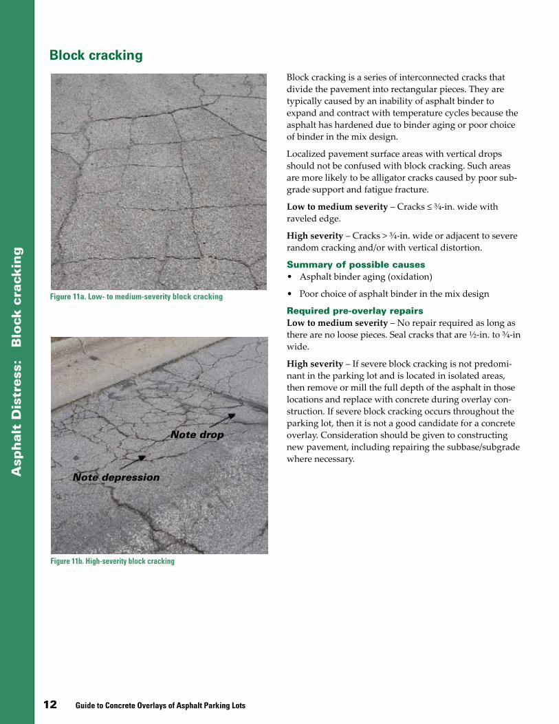
Block cracking is a series of interconnected cracks that divide the pavement into rectangular pieces. They are typically caused by an inability of asphalt binder to expand and contract with temperature cycles because the asphalt has hardened due to binder aging or poor choice of binder in the mix design.
Localized pavement surface areas with vertical drops should not be confused with block cracking. Such areas are more likely to be alligator cracks caused by poor sub-grade support and fatigue fracture.
Low to medium severity – Cracks ≤ ¾-in. wide with raveled edge.
High severity – Cracks > ¾-in. wide or adjacent to severe random cracking and/or with vertical distortion.
Summary of possible causes• Asphalt binder aging (oxidation)
• Poor choice of asphalt binder in the mix design
Required pre-overlay repairsLow to medium severity – No repair required as long as there are no loose pieces. Seal cracks that are ½-in. to ¾-in wide.
High severity – If severe block cracking is not predomi-nant in the parking lot and is located in isolated areas, then remove or mill the full depth of the asphalt in those locations and replace with concrete during overlay con-struction. If severe block cracking occurs throughout the parking lot, then it is not a good candidate for a concrete overlay. Consideration should be given to constructing new pavement, including repairing the subbase/subgrade where necessary.
Note drop
Note depression
Guide to Concrete Overlays of Asphalt Parking Lots 13
Asp
hal
t D
istr
ess:
P
oth
ole
s, p
op
ou
ts
Potholes, popouts
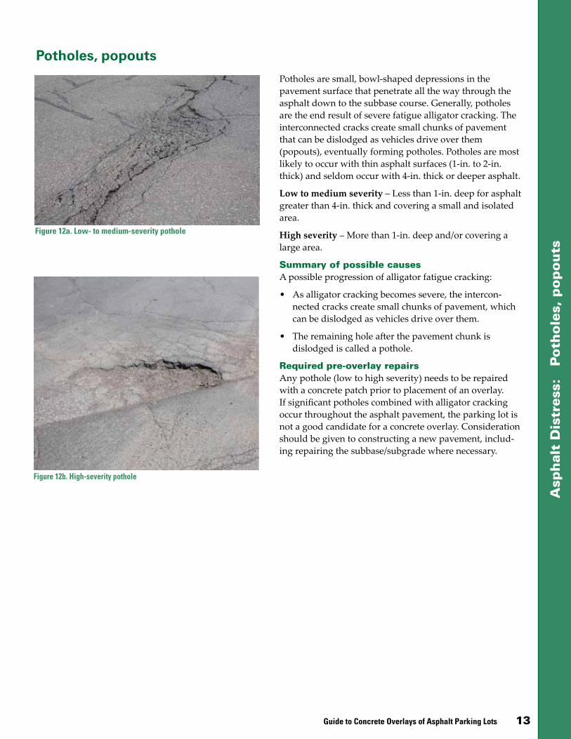
Figure 12a. Low- to medium-severity pothole
Figure 12b. High-severity pothole
Potholes are small, bowl-shaped depressions in the pavement surface that penetrate all the way through the asphalt down to the subbase course. Generally, potholes are the end result of severe fatigue alligator cracking. The interconnected cracks create small chunks of pavement that can be dislodged as vehicles drive over them (popouts), eventually forming potholes. Potholes are most likely to occur with thin asphalt surfaces (1-in. to 2-in. thick) and seldom occur with 4-in. thick or deeper asphalt.
Low to medium severity – Less than 1-in. deep for asphalt greater than 4-in. thick and covering a small and isolated area.
High severity – More than 1-in. deep and/or covering a large area.
Summary of possible causesA possible progression of alligator fatigue cracking:
• As alligator cracking becomes severe, the intercon-nected cracks create small chunks of pavement, which can be dislodged as vehicles drive over them.
• The remaining hole after the pavement chunk is dislodged is called a pothole.
Required pre-overlay repairsAny pothole (low to high severity) needs to be repaired with a concrete patch prior to placement of an overlay. If significant potholes combined with alligator cracking occur throughout the asphalt pavement, the parking lot is not a good candidate for a concrete overlay. Consideration should be given to constructing a new pavement, includ-ing repairing the subbase/subgrade where necessary.

14 Guide to Concrete Overlays of Asphalt Parking Lots
Asp
hal
t D
istr
ess:
R
avel
ing
Raveling
Raveling is the wearing away of the pavement surface as aggregate particles are dislodged. The cause can be the hardening of the asphalt binder, poor quality mix, or poor compaction. Progressive pavement disintegration occurs from the surface downward.
Low to medium severity – The aggregate or binder has worn away but has not progressed significantly. The surface is becoming rough or pitted with the loss of fine aggregate and some loss of coarse aggregate; loose par-ticles generally exist.
High severity – Aggregate or binder has worn away and the surface texture is very rough and pitted; loss of coarse aggregate.
Summary of possible causesRaveling is the result of loss of bond between aggregate particles and the asphalt binder, which may be caused by
• Dusty aggregate (the asphalt binder bonds with the dust rather than the aggregate)
• Aggregate segregation (where fine particles are miss-ing, the asphalt binder can bind only to the coarse particles at their relatively few contact points)
• Inadequate compaction during construction (high density is required to develop sufficient cohesion within the asphalt)
• Mechanical dislodging by certain types of traffic such as studded tires, snowplow blades, or tracked vehicles
Required pre-overlay repairsLow to medium severity – Remove all loose material by sweeping the asphalt surface, followed by cleaning with compressed air.
High severity – Mill the surface to remove material with a vertical displacement of 1 in. or more to create a flat surface for the overlay.
Figure 13a. Low- to medium-severity raveling
Figure 13b. High-severity raveling

Guide to Concrete Overlays of Asphalt Parking Lots 15
Asp
hal
t D
istr
ess:
T
her
mal
cra
ckin
g
Thermal cracking
Thermal cracking is a common form of asphalt park-ing lot deterioration in cold climates, primarily due to shrinkage of the asphalt during low temperatures com-bined with hardening of the asphalt binder. The cracks are weak zones where water seeps into and damages the road structure.
Low to medium severity – A crack ≤ ¾-in. wide or a sealed crack.
High severity – A crack with a width > ¾ in. with verti-cal distortion.
Summary of possible causes• Cold temperatures produce thermal stresses in
asphalt pavement.
• When the temperature drops, the asphalt binder in a pavement contracts more than the aggregate par-ticles, causing the asphalt film to get thinner around the aggregates. When the temperature drops signifi-cantly, the asphalt binder becomes brittle and thermal cracking is initiated.
Required pre-overlay repairsLow to medium severity – Seal cracks ½-in. to ¾-in. wide with crack sealant. If the width of the cracks is greater than the maximum size aggregate of the overlay, the cracks should be filled with fly ash slurry or flow-able fill. Such cracks are sealed to prevent keying of the concrete overlay.
High severity – When the width of the cracks is greater than the maximum size aggregate, fill with fly ash slurry or flowable fill. When there is noticeable vertical move-ment, and if the cracks are greater than 1½-in. wide, determine the cause of the drop and opening. If it is a subgrade or drainage issue, the existing asphalt pave-ment should be stabilized and drained prior to filling the cracks.
Figure 14a. Low- to medium-severity thermal cracking
Figure 14b. High-severity thermal cracking
Note drop, shift of asphalt
16 Guide to Concrete Overlays of Asphalt Parking Lots
Asp
hal
t D
istr
ess:
R
and
om
cra
ckin
g
Random cracking
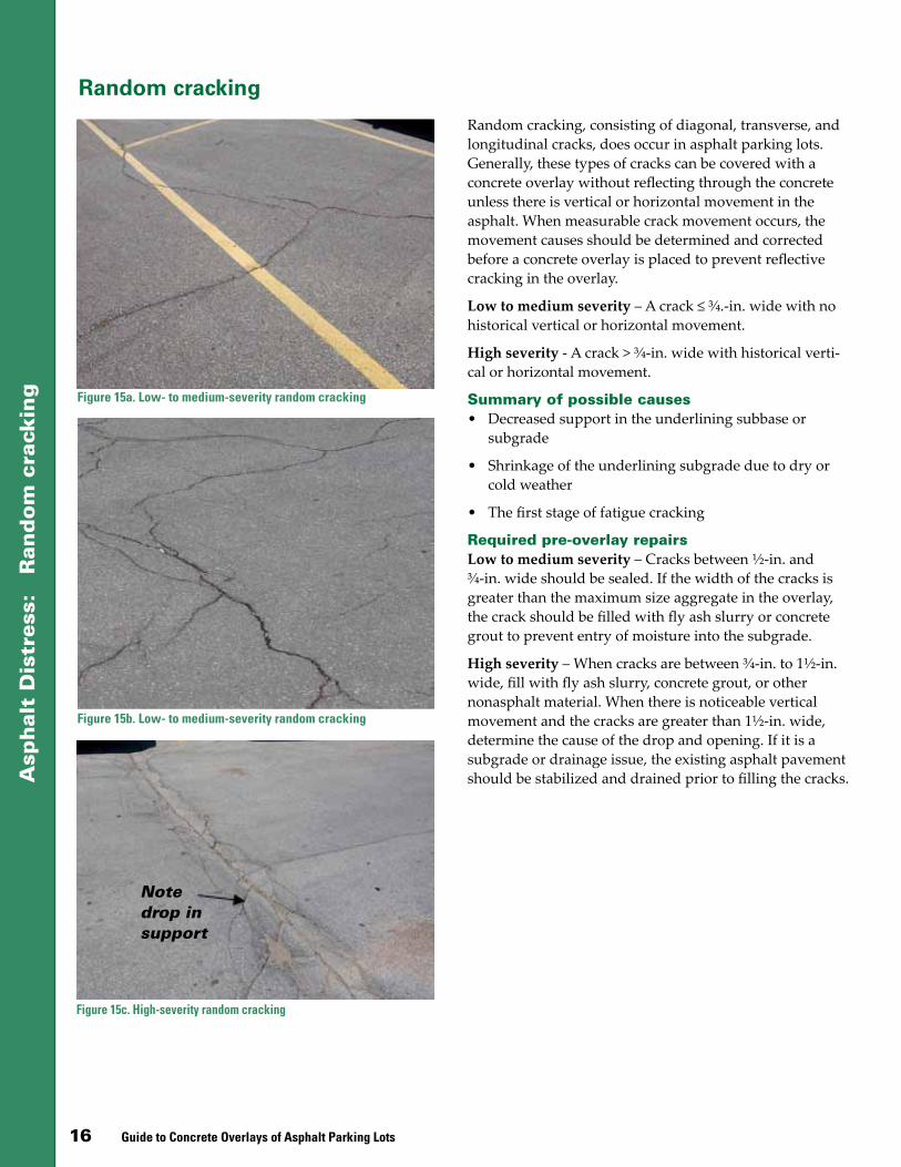
Random cracking, consisting of diagonal, transverse, and longitudinal cracks, does occur in asphalt parking lots. Generally, these types of cracks can be covered with a concrete overlay without reflecting through the concrete unless there is vertical or horizontal movement in the asphalt. When measurable crack movement occurs, the movement causes should be determined and corrected before a concrete overlay is placed to prevent reflective cracking in the overlay.
Low to medium severity – A crack ≤ ¾.-in. wide with no historical vertical or horizontal movement.
High severity - A crack > ¾-in. wide with historical verti-cal or horizontal movement.
Summary of possible causes• Decreased support in the underlining subbase or
subgrade
• Shrinkage of the underlining subgrade due to dry or cold weather
• The first stage of fatigue cracking
Required pre-overlay repairsLow to medium severity – Cracks between ½-in. and ¾-in. wide should be sealed. If the width of the cracks is greater than the maximum size aggregate in the overlay, the crack should be filled with fly ash slurry or concrete grout to prevent entry of moisture into the subgrade.
High severity – When cracks are between ¾-in. to 1½-in. wide, fill with fly ash slurry, concrete grout, or other nonasphalt material. When there is noticeable vertical movement and the cracks are greater than 1½-in. wide, determine the cause of the drop and opening. If it is a subgrade or drainage issue, the existing asphalt pavement should be stabilized and drained prior to filling the cracks.
Figure 15a. Low- to medium-severity random cracking
Figure 15b. Low- to medium-severity random cracking
Figure 15c. High-severity random cracking
Note drop in support
Guide to Concrete Overlays of Asphalt Parking Lots 17
Asp
hal
t D
istr
ess:
Acc
ess
or
tru
ck lan
e ru
ttin
g
Access or truck lane rutting
Figure 16a. Low- to medium-severity rutting
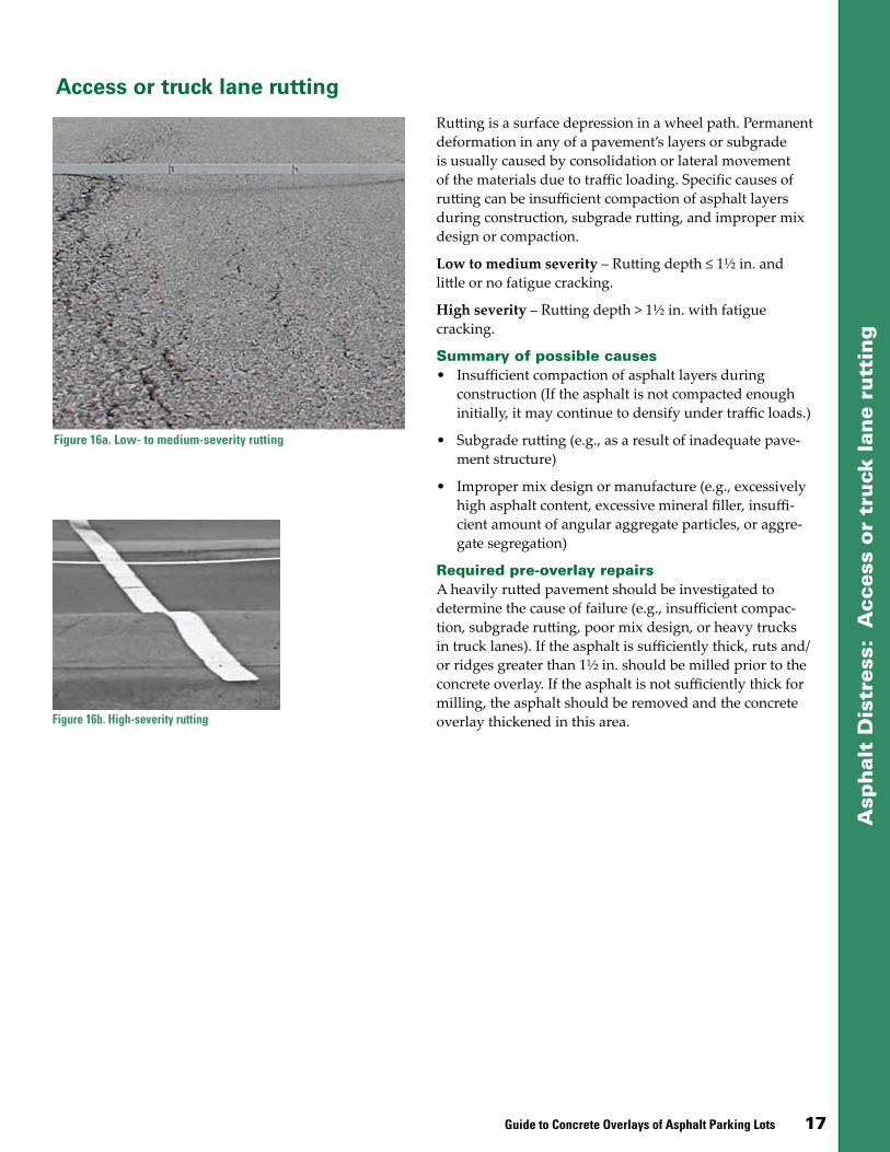
Rutting is a surface depression in a wheel path. Permanent deformation in any of a pavement’s layers or subgrade is usually caused by consolidation or lateral movement of the materials due to traffic loading. Specific causes of rutting can be insufficient compaction of asphalt layers during construction, subgrade rutting, and improper mix design or compaction.
Low to medium severity – Rutting depth ≤ 1½ in. and little or no fatigue cracking.
High severity – Rutting depth > 1½ in. with fatigue cracking.
Summary of possible causes• Insufficient compaction of asphalt layers during
construction (If the asphalt is not compacted enough initially, it may continue to densify under traffic loads.)
• Subgrade rutting (e.g., as a result of inadequate pave-ment structure)
• Improper mix design or manufacture (e.g., excessively high asphalt content, excessive mineral filler, insuffi-cient amount of angular aggregate particles, or aggre-gate segregation)
Required pre-overlay repairsA heavily rutted pavement should be investigated to determine the cause of failure (e.g., insufficient compac-tion, subgrade rutting, poor mix design, or heavy trucks in truck lanes). If the asphalt is sufficiently thick, ruts and/or ridges greater than 1½ in. should be milled prior to the concrete overlay. If the asphalt is not sufficiently thick for milling, the asphalt should be removed and the concrete overlay thickened in this area.Figure 16b. High-severity rutting

18 Guide to Concrete Overlays of Asphalt Parking Lots
Asp
hal
t D
istr
ess:
A
cces
s o
r tr
uck
lan
e sh
ovi
ng
(sl
ipp
age)
Access or truck lane shoving (slippage)
Figure 17a. Low- to medium-severity shoving
Figure 17b. High-severity shoving
Shoving (slippage) is a form of plastic movement typified by ripples (corrugation) or an abrupt wave (shoving) across the pavement surface. The distortion is perpendicular to the traffic direction. It usually occurs at locations where traffic starts and stops (corrugation) or where the asphalt abuts a rigid object (shoving).
Low to medium severity – Small, localized areas.
High severity – Large areas indicative of asphalt failure.
Summary of possible causes• Generally caused by braking or accelerating vehicles or
by a poor tack coat between asphalt lifts, and is usually associated with vertical displacement, particularly in truck lanes.
• May be caused by an unstable (i.e., low stiffness) asphalt layer due to mix contamination, poor mix design, or lack of aeration of the liquid emulsion.
Required pre-overlay repairsLow to medium severity – Remove the pavement with vertical distortions and replace with concrete during con-struction of the overlay.
High severity – Remove distorted pavement to extent of shoving. If shoving is predominant throughout the park-ing lot, then the asphalt pavement is not a good candidate for a concrete overlay. Consideration should be given to constructing a new pavement, including repairing the sub-base/subgrade where necessary.

Guide to Concrete Overlays of Asphalt Parking Lots 19
Concrete Overlay Design With few or no spot repairs, asphalt parking lots that have low- to medium-severity surface distress (as previously defined) can be enhanced with a 3- to 6-in. (50- to 125-mm) concrete overlay. The concrete overlay relies on the exist-ing asphalt to carry some traffic loading. The overlay bonds to the existing asphalt to form a monolithic pave-ment, thereby reducing stresses and deflections.
Maintaining the bond is especially critical during the first few days when the overlay is susceptible to curling and warping stresses, especially at the pavement edges. There-fore, the bond must be protected through thorough curing practices and by keeping early traffic away from the pavement edges until adequate bond strength is achieved (usually when opening strength has been achieved).
Probably one of the more challenging aspects of designing the thickness of bonded overlays on asphalt is the consid-eration of the supporting platform. For concrete overlays of asphalt pavement, the classic modulus of subgrade reaction, or k-value, described earlier, is based on the subbase/subgrade value under the asphalt layer. It does not consider the asphalt itself in the k-value, since asphalt is part of the new monolithic pavement thickness when concrete is bonded to it.
Table 3 compares composite k-values from ACI 330R-08. The American Concrete Pavement Association (ACPA) provides a composite k calculator; however, the ACI 330R-08 values are more conservative.
For this guide, the ACPA’s modified Bonded Concrete Over Asphalt (BCOA) program has been used to deter-mine overlay design thicknesses for light-vehicle asphalt parking lots. In the modified BCOA program, the existing asphalt’s remaining modulus of elasticity is considered. (The BCOA tool is available at http://apps.acpa.org/apps/bcoa.aspx.)
Both the ACPA’s original 1998 design procedure and its 2004 revised procedure for bonded concrete overlays on asphalt pavements were based on a single mode of failure—the corner break. The corner break model has worked adequately. In recent years, however, it has been recognized that the two most common precursors to fail-ure for bonded concrete overlays on asphalt are as follow:
• Delamination stemming from failure in the bond plane
• Failure in the underlying asphalt layer
Therefore, the most recent revisions of the design pro-cedure for this type of overlay reflect a “weakest link” approach, applying probabilistic techniques to all three modes of failure.
A unique design consideration for bonded overlays on asphalt pavements is the joint spacing to mitigate curling and warping stresses in the overlay. The joint spacing is affected by the thickness of the underlying asphalt and the thickness and flexural strength of the concrete overlay. Typically, the joint spacing, in feet, for concrete overlays ranges from 1 to 1.5 times the overlay thickness in inches. A good rule of thumb is to use 1.25 times the overlay thickness to obtain the spacing in feet, rounding to the nearest foot.
The recommended joint pattern for bonded concrete overlays of asphalt is small squares, typically in the range of 4 to 6 ft.
Overlay thicknessSeveral factors should be considered when selecting the thickness of the concrete overlay. The condition of the existing pavement and the traffic loading are the para-mount factors. When existing asphalt pavement has low- to medium-severity distress, the overlay can be successful.
Table 3. Composite k-values
Subgrade k- value, psi/in.*
Subbase thickness
4 in. 6 in. 9 in. 12 in.
Granular aggregate subbase
50 65 75 85 110
100 130 140 160 190
200 220 230 270 320
300 320 330 370 430
Cement-treated subbase
50 170 230 310 390
100 280 400 520 640
200 470 640 830 --
Other treated subbase
50 85 115 170 215
100 175 210 270 325
200 280 315 360 400
300 350 385 420 490Source: ACI 330R-08, Table 3.2* psi/in.= pci

20 Guide to Concrete Overlays of Asphalt Parking Lots
The ACPA design procedure is based on calculating the fatigue damage in the slab for a corner loading condition as well as limiting the fatigue damage at the bottom of the existing asphalt pavement at the transverse joint location (ACPA 1998). Temperature curling stresses are also con-sidered in the critical pavement response. One limitation of this method is that it is based on the Portland Cement Association (PCA) beam fatigue model, which is very conservative. A modified ACPA method was developed in 2006 by Riley, which incorporated a new probabilistic concrete fatigue algorithm (Riley et al. 2005).
In January 2011, the ACPA released a modified, bonded concrete overlay on asphalt (BCOA) thickness design web-based application that incorporates the work by Riley (2006) and Roesler et al. (2008). The modified BCOA method allows for the input of existing asphalt pavement properties, accounts for structural fibers, and checks for a potential bond plane failure. (This tool, available at http://apps.acpa.org/apps/bcoa.aspx, was used to determine the thicknesses of concrete overlays in parking lots with low- to medium-severity distresses provided on pages 23 through 25 of this guide.)
The inputs for the ACPA BCOA thickness design tool include the following:
• Equivalent single axle loads (ESALs)
• Percentage of allowable cracked slabs
• Reliability
• Effective temperature gradient and corresponding percentage time
• Existing asphalt pavement:
− Remaining asphalt thickness and modulus
− Composite k-value of subgrade/subbase*
• Concrete overlay:
− Strength, modulus, fiber type, and coefficient of thermal expansion (CTE)
− Proposed slab size and pre-overlay surface prepara-tion
*The analyses for this guide used composite k-values per ACI 330R-08.
It should be noted that, while the ACPA’s current modified BCOA method is suitable for designing bonded concrete overlays over asphalt parking lots, revisions to the soft-
ware are ongoing. Future updates will enhance some of the models and provide default inputs that will streamline the design process for locations throughout the United States. Specifically, it is important to note that this method offers the ability to consider project-specific temperature gradient inputs, although information may not be readily available to pavement designers.
The current default values in the ACPA web application for the effective temperature gradient and percentage time at the effective temperature gradient were developed by Roesler et al. (2008) based on field data for the State of Illinois. Feng and Vandenbossche (2012) have defined the equivalent temperature gradient based on the solar radia-tion present at the geographical location of the project within the United States; this feature is being incorporated into the BCOA procedure.
FibersIn general, the use of fiber reinforcement is not necessary in concrete overlays of parking lots serving light vehicles like cars and pickup trucks. In certain situations, howev-er—where, for example, vertical restrictions limit the over-lay thickness, heavier-weight traffic loads are expected, in-creased joint spacing is desirable, or conventional dowels cannot be used—the use of fibers may be warranted.
Although steel fibers have a long, successful history in paving applications, in the last two decades synthetic fibers have become predominant due to their ease of
Figure 18. Synthetic fibers

Guide to Concrete Overlays of Asphalt Parking Lots 21
Table 4 . Summary of Fiber Types
Fiber Type
Size (D = dia.)
(L = length)
Yrs Used
in U.S.
Typi-cal
Rate (lb/yd3 [pcy])
Comments
Micro Synthetic
D < 0.012 in. (0.3 mm)
L 0.50 to 2.25 in.
35 1.0 to 3.0
Reduces plastic shrinkage cracking and settlement cracking; limited effect on concrete overlay overall performance; more work- ability issues when using higher rates
Macro Synthetic
D > 0.012 in. (0.3 mm)
L 1.50 to 2.25 in.
15 3.0 to 7.5
Increases post-crack flexural performance, fatigue-impact endurance; thinner concrete thickness; longer joint spac-ing; tighter joints, cracks; better handling properties, dispersion characteristics than steel fibers; not subject to corrosion
Macro Steel (carbon)
L 0.75 to 2.50 in. 40 33 to
100
Increases strain strength, impact resistance, post-crack flexural performance, fatigue endurance, crack width control, per ACI 544.4R
Blended 15 Varies
Blend of small dosage of micro synthetic fibers and larger dosage of either macro synthetic fibers or macro steel fibers
Synthetic (polymer) fiber materials:• Polypropylene
• Monofilament (cylindrical) – Fibers of same length• Multifilament – Monofilament fibers of different lengths• Fibrillated (rectangular) - Net-shaped fiber collated in interconnected clips
• Polyester• Nylon
Table 5. Design Thicknesses for New Pavements
MOR/psik=50 psi/in.*
(CBR=2)k=100 psi/in.*
(CBR=3)k=200 psi/in.*
(CBR=10)
600 650 600 650 600 650
A (ADTT=1) 5.0 4.5 4.5 4.0 4.0 4.0
A (ADTT=10) 5.5 5.0 5.0 4.5 4.5 4.5
B (ADTT=25) 6.0 6.0 5.5 5.5 5.0 5.0
Notes: 20-year design thickness recommendations, in. (no dowels) ADTT = average daily truck traffic (vehicles w/at least 6 wheels,
excluding panel trucks) MOR = modulus of rupture
*psi/in. = pci
handling, better dispersion characteristics (i.e., less “ball-ing”), and resistance to rust damage. See Figure 18.
Whether steel or synthetic fibers are used, the volume of fibers in a concrete mixture is expressed as a percentage of the total volume of the composite (concrete and fibers). The exact dosage is specified to produce certain behavior characteristics in the concrete.
In appropriate dosages, fibers can perform the following functions in a concrete mixture:
• Help increase concrete toughness (allowing thinner concrete slabs and/or longer joint spacing)
• Help control differential slab movement caused by curling/warping, heavy loads, temperatures, etc. (allowing longer joint spacing)
• Increase concrete’s resistance to plastic shrinkage crack-ing (enhancing aesthetics and concrete performance)
• Hold cracks tightly together (enhancing aesthetics and concrete performance)
Table 4 provides a summary of current categories of fibers, with general descriptions and application rates. For a more detailed discussion of fibers, see the Appendix, Fiber-Reinforced Concrete.
New pavement design (unbonded overlays)When an asphalt parking lot has high-severity distresses as described earlier, it is recommended that a bonded concrete overlay not be constructed, but rather a new concrete pavement (i.e., an unbonded concrete overlay) be constructed.
Table 5, developed from Table 3.4 of ACI 330R-08, lists the minimum thicknesses for new concrete pavements based on the existing condition of the underlying pavement (base) and future loadings. These are based on calculated stresses and fatigue resistance from the Portland Cement Association’s design procedure (Packard 1984). The thick-nesses are rounded to the nearest half inch.
For thickness design of new concrete pavement for park-ing lots for light vehicle traffic (cars and pickup trucks), Table 5 is the preferred approach. It is recommended that all phases of design for new concrete pavements with little or no truck traffic follow ACI 330R-08.

22 Guide to Concrete Overlays of Asphalt Parking Lots
Parking lot zone overlay designWhen sections of an asphalt parking lot have significantly different traffic loadings, the concrete overlay can and should be designed as separate sections or zones. For example, parking lot areas with light traffic (cars or pickup trucks) may allow reduced overlay thickness, while access ways and truck lanes such as delivery routes may require thicker overlays. Figure 19 shows a typical parking lot layout with three different zones that should be designed separately. Note: Not all parking lots have all three zones.
On the following pages, Tables 6–8 list common design thicknesses for the majority of concrete overlays on exist-ing asphalt parking lots. Each table is divided into three sections, one for each of the three parking lot zones identi-fied in Figure 19. The overlay design thicknesses were developed using the ACPA’s modified BCOA program, described earlier (based on FHWA-ICT-08-016, Design and Concrete Material Requirements for Ultra-Thin Whitetopping). (The BCOA program can be found at http://apps.acpa.org/apps/bcoa.aspx.)
The three tables provide overlay thicknesses for three geographical areas in the United States with different mean annual daily temperatures (MADT). Table 6 repre-sents an MADT of 45–50°F (e.g., Iowa); Table 7, an MADT of 55–60°F (e.g. Sacramento, CA); and Table 8, an MADT of 65–70°F (e.g., Gainesville, FL). Some areas in the coun-try have lower MADTs (e.g., North Dakota with 32–40°F) or higher MADTs (e.g., Arizona with ≥ 70°F). Therefore, when using the BCOA program for any specific overlay project, the designer should enter the major city closest to the project site when prompted for “location”; the pro-gram will automatically account for the correct MADT in the thickness design.
In developing Tables 6–8, several iterations of the BCOA program were conducted to determine trends in overlay thickness design by varying
Figure 19. The “zone design” concept for parking lots assumes that access roads, truck lanes, and general parking areas experience different traffic loadings and, thus, the concrete overlays for those zones should be designed separately
Zone 1 - Parking lotsZone 2 - Access roadsZone 3 - Truck lanes
Building
the joint spacing, the use of macro fibers, concrete flexural strength, existing asphalt thickness, and traffic loads. The following general trends were observed:
• Higher aggregate coefficient of thermal expansion increases the required concrete overlay thickness. A change from limestone (4.34 x 10⁻⁶ in./in./°F) to chert (6.01 x 10⁻⁶ in./in./°F) increases the overlay thickness by up to 0.5 in.
• The k-value has minimal effect on the concrete thick-ness based on k-values of 50, 100, and 200 pci.
The following design assumptions were used:
• 20-year Design Life
• 50 percent Directional Distribution Factor
• 75 percent Design Lane Distribution Factor
• 2 percent Growth Rate
• 30 percent Cracked Slabs at End of Design Life
• 80 percent Reliability
• 300,000 psi Asphalt Modulus of Elasticity
• 100 pci k-value (under the asphalt)
• 25 percent Residual Strength Ratio (with fibers)
• 3,600,000 psi Concrete Modulus of Elasticity
• Pre-overlay Surface Preparation: existing asphalt is cleaned only (not milled)
• Coefficient of thermal expansion is based on limestone
• Thickness values are rounded up to the nearest 0.5 in.
Note: Tables 6–8 are to be used for general reference pur-poses only. For design purposes, actual overlay thickness should be determined based on specific design variables for the project, using the ACPA’s modified BCOA program.
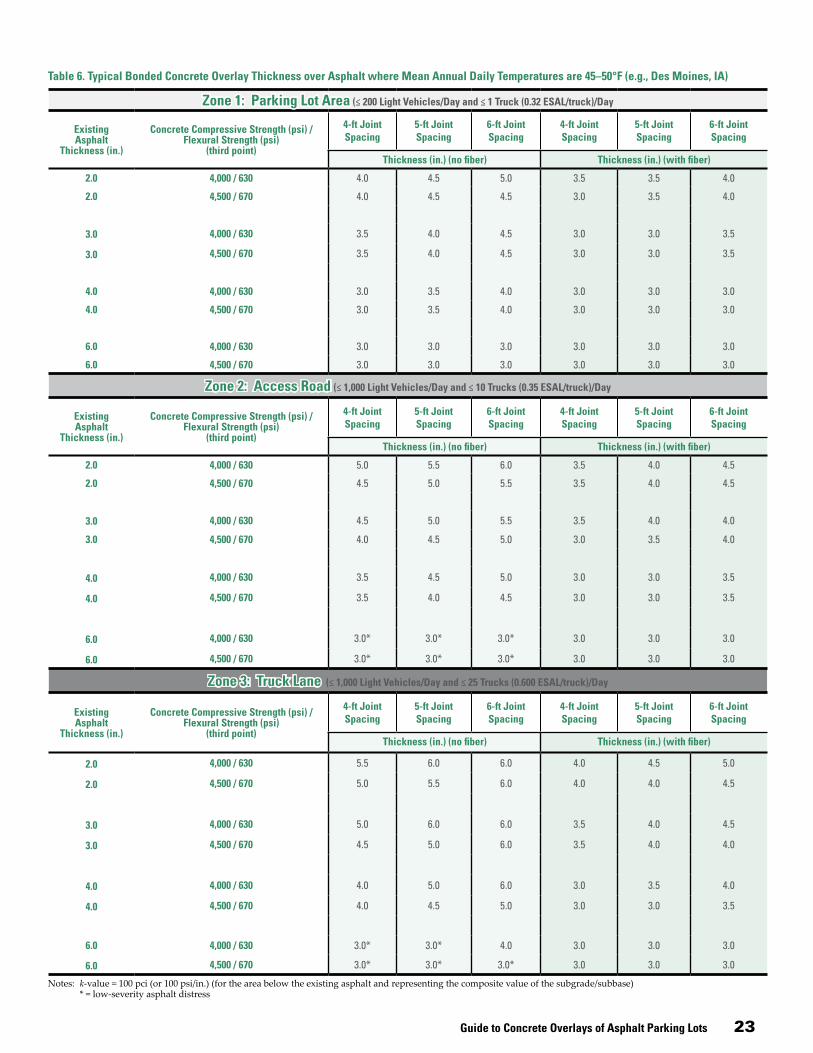
Guide to Concrete Overlays of Asphalt Parking Lots 23
Notes: k-value = 100 pci (or 100 psi/in.) (for the area below the existing asphalt and representing the composite value of the subgrade/subbase) * = low-severity asphalt distress
Table 6. Typical Bonded Concrete Overlay Thickness over Asphalt where Mean Annual Daily Temperatures are 45–50°F (e.g., Des Moines, IA)
Zone 1: Parking Lot Area (≤ 200 Light Vehicles/Day and ≤ 1 Truck (0.32 ESAL/truck)/Day
Existing Asphalt
Thickness (in.)
Concrete Compressive Strength (psi) / Flexural Strength (psi)
(third point)
4-ft Joint Spacing
5-ft Joint Spacing
6-ft Joint Spacing
4-ft Joint Spacing
5-ft Joint Spacing
6-ft Joint Spacing
Thickness (in.) (no fiber) Thickness (in.) (with fiber)
2.0 4,000 / 630 4.0 4.5 5.0 3.5 3.5 4.0
2.0 4,500 / 670 4.0 4.5 4.5 3.0 3.5 4.0
3.0 4,000 / 630 3.5 4.0 4.5 3.0 3.0 3.5
3.0 4,500 / 670 3.5 4.0 4.5 3.0 3.0 3.5
4.0 4,000 / 630 3.0 3.5 4.0 3.0 3.0 3.0
4.0 4,500 / 670 3.0 3.5 4.0 3.0 3.0 3.0
6.0 4,000 / 630 3.0 3.0 3.0 3.0 3.0 3.0
6.0 4,500 / 670 3.0 3.0 3.0 3.0 3.0 3.0
Zone 2: Access Road (≤ 1,000 Light Vehicles/Day and ≤ 10 Trucks (0.35 ESAL/truck)/Day
Existing Asphalt
Thickness (in.)
Concrete Compressive Strength (psi) / Flexural Strength (psi)
(third point)
4-ft Joint Spacing
5-ft Joint Spacing
6-ft Joint Spacing
4-ft Joint Spacing
5-ft Joint Spacing
6-ft Joint Spacing
Thickness (in.) (no fiber) Thickness (in.) (with fiber)
2.0 4,000 / 630 5.0 5.5 6.0 3.5 4.0 4.5
2.0 4,500 / 670 4.5 5.0 5.5 3.5 4.0 4.5
3.0 4,000 / 630 4.5 5.0 5.5 3.5 4.0 4.0
3.0 4,500 / 670 4.0 4.5 5.0 3.0 3.5 4.0
4.0 4,000 / 630 3.5 4.5 5.0 3.0 3.0 3.5
4.0 4,500 / 670 3.5 4.0 4.5 3.0 3.0 3.5
6.0 4,000 / 630 3.0* 3.0* 3.0* 3.0 3.0 3.0
6.0 4,500 / 670 3.0* 3.0* 3.0* 3.0 3.0 3.0
Zone 3: Truck Lane (≤ 1,000 Light Vehicles/Day and ≤ 25 Trucks (0.600 ESAL/truck)/Day
Existing Asphalt
Thickness (in.)
Concrete Compressive Strength (psi) / Flexural Strength (psi)
(third point)
4-ft Joint Spacing
5-ft Joint Spacing
6-ft Joint Spacing
4-ft Joint Spacing
5-ft Joint Spacing
6-ft Joint Spacing
Thickness (in.) (no fiber) Thickness (in.) (with fiber)
2.0 4,000 / 630 5.5 6.0 6.0 4.0 4.5 5.0
2.0 4,500 / 670 5.0 5.5 6.0 4.0 4.0 4.5
3.0 4,000 / 630 5.0 6.0 6.0 3.5 4.0 4.5
3.0 4,500 / 670 4.5 5.0 6.0 3.5 4.0 4.0
4.0 4,000 / 630 4.0 5.0 6.0 3.0 3.5 4.0
4.0 4,500 / 670 4.0 4.5 5.0 3.0 3.0 3.5
6.0 4,000 / 630 3.0* 3.0* 4.0 3.0 3.0 3.0
6.0 4,500 / 670 3.0* 3.0* 3.0* 3.0 3.0 3.0

24 Guide to Concrete Overlays of Asphalt Parking Lots
Zone 1: Parking Lot Area (≤ 200 Light Vehicles/Day and ≤ 1 Truck (0.32 ESAL/truck)/Day
Existing Asphalt
Thickness (in.)
Concrete Compressive Strength (psi) / Flexural Strength (psi)
(third point)
4-ft Joint Spacing
5-ft Joint Spacing
6-ft Joint Spacing
4-ft Joint Spacing
5-ft Joint Spacing
6-ft Joint Spacing
Thickness (in.) (no fiber) Thickness (in.) (with fiber)
2.0 4,000 / 630 4.5 5.0 5.5 3.5 4.0 4.0
2.0 4,500 / 670 4.0 4.5 5.0 3.5 3.5 4.0
3.0 4,000 / 630 4.0 4.5 5.0 3.0 3.5 3.5
3.0 4,500 / 670 4.0 4.5 5.0 3.0 3.5 3.5
4.0 4,000 / 630 3.5 4.0 4.5 3.0 3.0 3.0
4.0 4,500 / 670 3.0 3.5 4.5 3.0 3.0 3.0
6.0 4,000 / 630 3.0 3.0 3.0 3.0 3.0 3.0
6.0 4,500 / 670 3.0 3.0 3.0 3.0 3.0 3.0
Zone 2: Access Road (≤ 1,000 Light Vehicles/Day and ≤ 10 Trucks (0.35 ESAL/truck)/Day
Existing Asphalt
Thickness (in.)
Concrete Compressive Strength (psi)/ Flexural Strength (psi)
(third point)
4-ft Joint Spacing
5-ft Joint Spacing
6-ft Joint Spacing
4-ft Joint Spacing
5-ft Joint Spacing
6-ft Joint Spacing
Thickness (in.) (no fiber) Thickness (in.) (with fiber)
2.0 4,000 / 630 5.5 6.0 6.0 4.0 4.5 5.0
2.0 4,500 / 670 5.0 6.0 6.0 4.0 4.0 4.5
3.0 4,000 / 630 5.0 6.0 6.0 3.5 4.0 4.5
3.0 4,500 / 670 4.5 5.5 6.0 3.5 4.0 4.5
4.0 4,000 / 630 4.5 5.5 6.0 3.0 3.5 4.0
4.0 4,500 / 670 4.0 5.0 5.5 3.0 3.0 3.5
6.0 4,000 / 630 3.0* 3.5 4.5 3.0 3.0 3.0
6.0 4,500 / 670 3.0* 3.0* 3.5 3.0 3.0 3.0
Zone 3: Truck Lane (≤ 1,000 Light Vehicles/Day and ≤ 25 Trucks (0.600 ESAL/truck)/Day
Existing Asphalt
Thickness (in.)
Concrete Compressive Strength (psi)/ Flexural Strength (psi)
(third point)
4-ft Joint Spacing
5-ft Joint Spacing
6-ft Joint Spacing
4-ft Joint Spacing
5-ft Joint Spacing
6-ft Joint Spacing
Thickness (in.) (no fiber) Thickness (in.) (with fiber)
2.0 4,000 / 630 6.0 6.0 6.0 4.5 5.0 5.5
2.0 4,500 / 670 6.0 6.0 6.0 4.0 4.5 5.0
3.0 4,000 / 630 6.0 6.0 6.0 4.0 4.5 5.0
3.0 4,500 / 670 5.5 6.0 6.0 3.5 4.0 4.5
4.0 4,000 / 630 5.5 6.0 6.0 3.5 4.0 4.5
4.0 4,500 / 670 5.0 6.0 6.0 3.0 3.5 4.0
6.0 4,000 / 630 3.0* 4.5 6.0 3.0 3.0 3.0
6.0 4,500 / 670 3.0* 3.5 4.5 3.0 3.0 3.0
Table 7. Typical Bonded Concrete Overlay Thickness over Asphalt where Mean Annual Daily Temperatures are 55–60°F (e.g., Sacramento, CA)
Notes: k-value = 100 pci (or 100 psi/in.) (for the area below the existing asphalt and representing the composite value of the subgrade/subbase) * = low-severity asphalt distress

Guide to Concrete Overlays of Asphalt Parking Lots 25
Notes: k-value = 100 pci (or 100 psi/in.) (for the area below the existing asphalt and representing the composite value of the subgrade/subbase) * = low-severity asphalt distress
Table 8. Typical Bonded Concrete Overlay Thickness over Asphalt where Mean Annual Daily Temperatures are 65–70°F (e.g., Gainesville, FL)
Zone 1: Parking Lot Area (≤ 200 Light Vehicles/Day and ≤ 1 Truck (0.32 ESAL/truck)/Day
Existing Asphalt
Thickness (in.)
Concrete Compressive Strength (psi) / Flexural Strength (psi)
(third point)
4-ft Joint Spacing
5-ft Joint Spacing
6-ft Joint Spacing
4-ft Joint Spacing
5-ft Joint Spacing
6-ft Joint Spacing
Thickness (in.) (no fiber) Thickness (in.) (with fiber)
2.0 4,000 / 630 4.5 5.0 5.0 3.5 4.0 4.0
2.0 4,500 / 670 4.0 4.5 5.0 3.0 3.5 4.0
3.0 4,000 / 630 4.0 4.5 5.0 3.0 3.5 3.5
3.0 4,500 / 670 3.5 4.0 4.5 3.0 3.0 3.5
4.0 4,000 / 630 3.0 4.0 4.5 3.0 3.0 3.0
4.0 4,500 / 670 3.0 3.5 4.0 3.0 3.0 3.0
6.0 4,000 / 630 3.0 3.0 3.0 3.0 3.0 3.0
6.0 4,500 / 670 3.0 3.0 3.0 3.0 3.0 3.0
Zone 2: Access Road (≤ 1,000 Light Vehicles/Day and ≤ 10 Trucks (0.35 ESAL/truck)/Day
Existing Asphalt
Thickness (in.)
Concrete Compressive Strength (psi) / Flexural Strength (psi)
(third point)
4-ft Joint Spacing
5-ft Joint Spacing
6-ft Joint Spacing
4-ft Joint Spacing
5-ft Joint Spacing
6-ft Joint Spacing
Thickness (in.) (no fiber) Thickness (in.) (with fiber)
2.0 4,000 / 630 5.0 6.0 6.0 4.0 4.5 4.5
2.0 4,500 / 670 4.5 5.5 6.0 3.5 4.0 4.5
3.0 4,000 / 630 4.5 5.5 6.0 3.5 4.0 4.5
3.0 4,500 / 670 4.5 5.0 5.5 3.0 3.5 4.0
4.0 4,000 / 630 4.0 5.0 5.5 3.0 3.0 3.5
4.0 4,500 / 670 3.5 4.5 5.0 3.0 3.0 3.5
6.0 4,000 / 630 3.0* 3.0* 3.5 3.0 3.0 3.0
6.0 4,500 / 670 3.0* 3.0* 3.0* 3.0 3.0 3.0
Zone 3: Truck Lane (≤ 1,000 Light Vehicles/Day and ≤ 25 Trucks (0.600 ESAL/truck)/Day
Existing Asphalt
Thickness (in.)
Concrete Compressive Strength (psi) / Flexural Strength (psi)
(third point)
4-ft Joint Spacing
5-ft Joint Spacing
6-ft Joint Spacing
4-ft Joint Spacing
5-ft Joint Spacing
6-ft Joint Spacing
Thickness (in.) (no fiber) Thickness (in.) (with fiber)
2.0 4,000 / 630 6.0 6.0 6.0 4.0 4.5 5.0
2.0 4,500 / 670 5.0 6.0 6.0 4.0 4.5 4.5
3.0 4,000 / 630 5.5 6.0 6.0 3.5 4.0 4.5
3.0 4,500 / 670 5.0 5.5 6.0 3.5 4.0 4.5
4.0 4,000 / 630 4.5 5.5 6.0 3.0 3.5 4.0
4.0 4,500 / 670 4.0 5.0 5.5 3.0 3.5 4.0
6.0 4,000 / 630 3.0* 3.5 4.5 3.0 3.0 3.0
6.0 4,500 / 670 3.0* 3.0* 3.5 3.0 3.0 3.0

26 Guide to Concrete Overlays of Asphalt Parking Lots
Special design considerations for two-inch concrete overlaysAlthough 2-in. concrete overlays of asphalt parking lots have been successful (see Figure 12), their design and con-struction do require special attention. In particular, short joint spacing that allows the concrete overlay to deflect in-stead of bend can reduce load stresses in the concrete slab to reasonable values, even at thicknesses as low as 2 in. The differential thermal movement between the asphalt and concrete is addressed by the short concrete overlay joint spacing. In addition, the short joint spacing reduces curling and warping stresses in the concrete overlay.
Some computer programs such as ACPA’s modified BCOA program use a minimum overlay design thickness of 3 in. Other programs such as the American Association of State Highway and Transportation Officials program (AASHTO 1993), ACPA’s StreetPave (ACPA 2012), and the National Ready Mixed Concrete Association (NRMCA) Concrete Pavement Analyst Software have a minimum thickness of 4 in. Therefore, a 2-in. thickness is not readily calculated with existing software, although a 2-in. thickness design is possible using charts and tables of the different overlay methods.
Asphalt parking lots in need of increased structural capac-ity can be candidates for 2-in. bonded concrete overlays if the following conditions can be met:
• Area is strictly limited to cars and other light vehicles.• Existing asphalt pavement is at least 4-in. thick and has
low- to medium-severity distress.
• The modulus of subgrade reaction (k) is 100 psi/in. or greater, or the CBR value is 3 or greater.
• A minimum thickness of 2.5 in. of asphalt—and prefer-ably more—remains after milling.
• High-volume synthetic macro fibers are used in the concrete overlay at a rate of 4 lb/yd3.
• Flexural strength of the concrete overlay is 700 psi at 28 days based on third-point loading.
• A maximum 3 ft by 3 ft joint spacing is used.
Jointing for Concrete OverlaysSee jointing details and other construction details begin-ning on page 30.
Joints are placed in concrete pavements to minimize ran-dom cracking and facilitate construction. The three types of joints that are commonly used in concrete pavement are contraction joints, construction joints, and isolation joints.
The designer should review and approve a contractor’s layout of joints and joint details.
In parking areas, the use of isolation joints should be limited to locations that isolate a structure, embedment, or existing pavement from the new pavement. With the designer’s approval, construction joint details and contrac-tion joint details can be interchanged to suit the contrac-tor’s method of construction and placement schedule.
Figure 21 illustrates a typical parking lot, access way, and trucking lane jointing pattern.
The recommended joint pattern for bonded overlays of asphalt is small, square panels, typically in the range of 4 to 6 ft. This jointing design helps reduce curling and warping stresses in the concrete as well as differential movements of the concrete overlay and the asphalt. It is normally recommended that the length and width of joint squares in feet be limited to 1.5 times the overlay thickness in inches.
Sometimes accommodations have to be made for fixed objects, especially in parking lots. The intent is to maintain nominal specified joint spacing, while permitting gradual joint spacing adjustments of up to +/- 10 percent in the last two or three panels adjacent to the fixed point. In park-ing lot areas that are expected to experience significant heavy-truck traffic, it is better to decrease the joint spac-ing if possible in the last two or three panels adjacent to
Figure 20. Two-in. thick concrete overlay on +/- 2.5-in. thick asphalt parking lot with 6 to 8 in. of stone; age approximately 8 years when photo taken
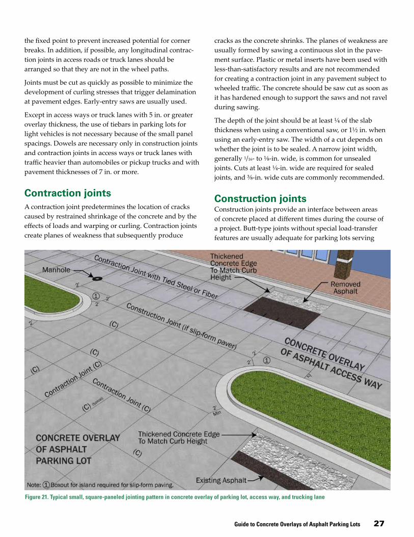
Guide to Concrete Overlays of Asphalt Parking Lots 27
the fixed point to prevent increased potential for corner breaks. In addition, if possible, any longitudinal contrac-tion joints in access roads or truck lanes should be arranged so that they are not in the wheel paths.
Joints must be cut as quickly as possible to minimize the development of curling stresses that trigger delamination at pavement edges. Early-entry saws are usually used.
Except in access ways or truck lanes with 5 in. or greater overlay thickness, the use of tiebars in parking lots for light vehicles is not necessary because of the small panel spacings. Dowels are necessary only in construction joints and contraction joints in access ways or truck lanes with traffic heavier than automobiles or pickup trucks and with pavement thicknesses of 7 in. or more.
Contraction jointsA contraction joint predetermines the location of cracks caused by restrained shrinkage of the concrete and by the effects of loads and warping or curling. Contraction joints create planes of weakness that subsequently produce
cracks as the concrete shrinks. The planes of weakness are usually formed by sawing a continuous slot in the pave-ment surface. Plastic or metal inserts have been used with less-than-satisfactory results and are not recommended for creating a contraction joint in any pavement subject to wheeled traffic. The concrete should be saw cut as soon as it has hardened enough to support the saws and not ravel during sawing.
The depth of the joint should be at least ¼ of the slab thickness when using a conventional saw, or 1½ in. when using an early-entry saw. The width of a cut depends on whether the joint is to be sealed. A narrow joint width, generally 1/16- to ⅛-in. wide, is common for unsealed joints. Cuts at least ¼-in. wide are required for sealed joints, and ⅜-in. wide cuts are commonly recommended.
Construction joints Construction joints provide an interface between areas of concrete placed at different times during the course of a project. Butt-type joints without special load-transfer features are usually adequate for parking lots serving
Figure 21. Typical small, square-paneled jointing pattern in concrete overlay of parking lot, access way, and trucking lane

28 Guide to Concrete Overlays of Asphalt Parking Lots
light vehicles. Keyed joints should be avoided in concrete overlays regardless of the load. Keyed joints can lose con-tact between the keys when the joint opens due to drying shrinkage, eventually causing a breakdown of the joint edges and failure of the top of the key.
Isolation joints Where concrete overlays of different thicknesses come together, such as between vehicle parking areas and truck lanes or access ways, an isolation joint needs to be placed to allow movement between the slabs. Concrete slabs should be separated from fixed objects and the abutting paved area to offset the effects of expected differential hor-izontal and longitudinal movements. Isolation joints are not recommended along the face of curb and gutter abut-ting pavement. Pavement joints of any type that intersect this junction should extend through the curb and gutter. Isolation joints are not needed to accommodate expansion when contraction joints are properly spaced.
Dowel joints in access and truck lanes The need for dowels for load transfer across joints should be considered in areas carrying heavier loads, such as access ways and truck lanes. They are not necessary in parking lot areas with light loads.
Designers should recognize that when new concrete, with an inherent tendency to shrink, is tied to older concrete, which has already gone through the shrinkage process, stresses will develop that can cause cracking.
If the slab thickness was established based on the assump-tion of load transfer by aggregate interlock, joints should be doweled or slab edges thickened approximately 20 percent.
Dowels across pavement joints can provide load transfer while permitting the joints to move. Dowels may be eco-nomically justified where there are poor subgrade support conditions and/or heavy-truck traffic if improved joint performance would allow a significant reduction in thick-ness. Dowel baskets should be used at contraction joints to maintain alignment, or dowel bar inserters can be used on slipformed placements.
Rounded dowelsDowel size should be in proportion to the pavement thick-ness. Recommended sizes of smooth, round dowel bars for different slab thicknesses are 1 in. diameter for 7-in.
thick slab; 1.25-in. diameter for ≥ 8 in. to <10 in. slab; and 1.5-in. diameter for ≥ 10-in. slab.
Round dowels should be epoxy coated in areas where deicing salts are used. Round dowels should be placed at least 12 in. apart and at least 12 in. from a joint intersection to minimize the potential for corner cracking (ACI 360R, Schrader 1987, Schrader 1991.) The use of round dowels in pavements with two-directional doweling or in adjacent panels or lanes constructed at different times can also create restraint, stresses, and cracking (Schrader 1987, Schrader 1991).
Plate dowels Plate dowels have been used in contraction and construc-tion joints for parking lots, particularly in warm weather climates. Because of the larger horizontal surface area of plate dowels versus round dowels, the bearing pressure on the plate dowel and concrete is reduced along with restraint and stresses, minimizing random cracking.
Compared to round dowels, plate dowels can be placed closer to joint intersections but no closer than 6 in.
Manufacturers offer various plate dowel geometrics and associated installation devices. The shrinkage restraint is reduced by using a tapered shape or formed void or by having compressible material on the vertical faces with a thin bond breaker on the top and bottom dowel surfaces, per ACI 360R-10. The tapered shape along with a thin bond breaker on all sides allows a void space to develop along the vertical sides of the dowel, eliminating restraint as the slab shrinks from the joint. Similarly, a formed void or compressible material can also eliminate restraint as the slab shrinks from the joint.
Because of the various plate dowel geometries and instal-lation devices available, the individual manufacturers’ published engineering reports should be consulted to determine optimum dowel size and spacing for a specific project.
Plate load-transfer devices are also useful in other pave-ment applications where joints should have load-transfer capability while allowing some differential movement in the direction of the joint, per ACI 302.1R-04, such as might be necessary in pavements with two-directional doweling and odd-shaped panels. The use of plate dow-els in parking lots exposed to deicing salts is limited. It is recommended that a proven and tested corrosion resistant surface be applied to these dowels when exposed to deic-ing salts.

Guide to Concrete Overlays of Asphalt Parking Lots 29
Raising Existing Curb and Gutter One feature that frequently distinguishes parking lot over-lay applications from roadway overlay applications is the presence of an existing concrete curb and gutter system. In parking lots, curb and gutter may serve a variety of pur-poses in addition to drainage, such as separating parking zones, creating decorative medians complete with trees and plantings, acting as vehicle “bumper blocks,” and/or delineating the perimeter of the facility.
Frequently, accommodating fixed elevation points such as curb and gutter is the most challenging parking lot overlay design and construction issue, even more so than determining the design thickness. The contractor must consider necessary adjustments to attain or retain Americans with Disabilities Act–compliant ramps and sidewalks, for example, and to retain or enhance drainage.
New curb and gutter is not necessarily required. It is usually possible and relatively easy to “cap” the curb, or the curb can be milled. The new cap is frequently placed by hand (Figure 22) to accommodate local anomalies and irregularities. Small slipform paving machines can be used if sufficient quantities of curb and gutter exist to warrant their use (Figures 23 and 24). With certain equipment, the existing curb can be used for grade and elevation control.
The ends can be feathered to near-zero thickness, or short full-depth end sections may be recast depending on the grades and other controlling elevation points.
Since overlays of existing concrete curb and gutter are bonded concrete-on-concrete solutions, it is important that the existing curb and gutter be prepared to promote bonding. Extensive testing over many years has revealed that the best bond is usually obtained on a surface that is clean and effectively dry. A simple water blasting or, in rare instances, sand blasting is adequate to remove dirt and provide a clean surface. (Occasionally, depending on the type and age of pavement marking material used, a concrete overlay will not bond to a painted curb. A few paint stripes are generally not an issue, but a completely painted curb should be sand blasted clean of paint.) A surface that is on the dry side of saturated surface dry is optimum, but that can be difficult to establish during typical field operations.
If the existing surface is adequately clean and dry, a typi-cal ready mixed concrete mixture contains sufficient free
mortar to ensure that the overlay will adhere without further preparation or the use of a bonding agent. The mixture itself can be the same as that used for the parking lot or it can be a mixture using a smaller aggregate top size if better finishing characteristics are desired; this may be the case given the relatively small volume of concrete being used per linear foot of curb.
A good curing compound should be applied on all exposed fresh concrete, both on the front face and back of the curb. Normal application rates are fine. Care should be taken to prevent or minimize overspray onto adjacent curb sections and onto adjacent asphalt pavement yet to be overlaid; the compound could interfere with the concrete-on-concrete and concrete-on-asphalt bond, respectively.
Figure 22. Finishers “capping” existing curb and gutter; the form line is the edge of the asphalt and existing curb, and another form is used at the back of the curb (Photo courtesy of Jim Amundsen, Grace Construction Products)
Figure 23. Completed curb section ready for overlay placement
Figure 24. Slipform curb over existing curb
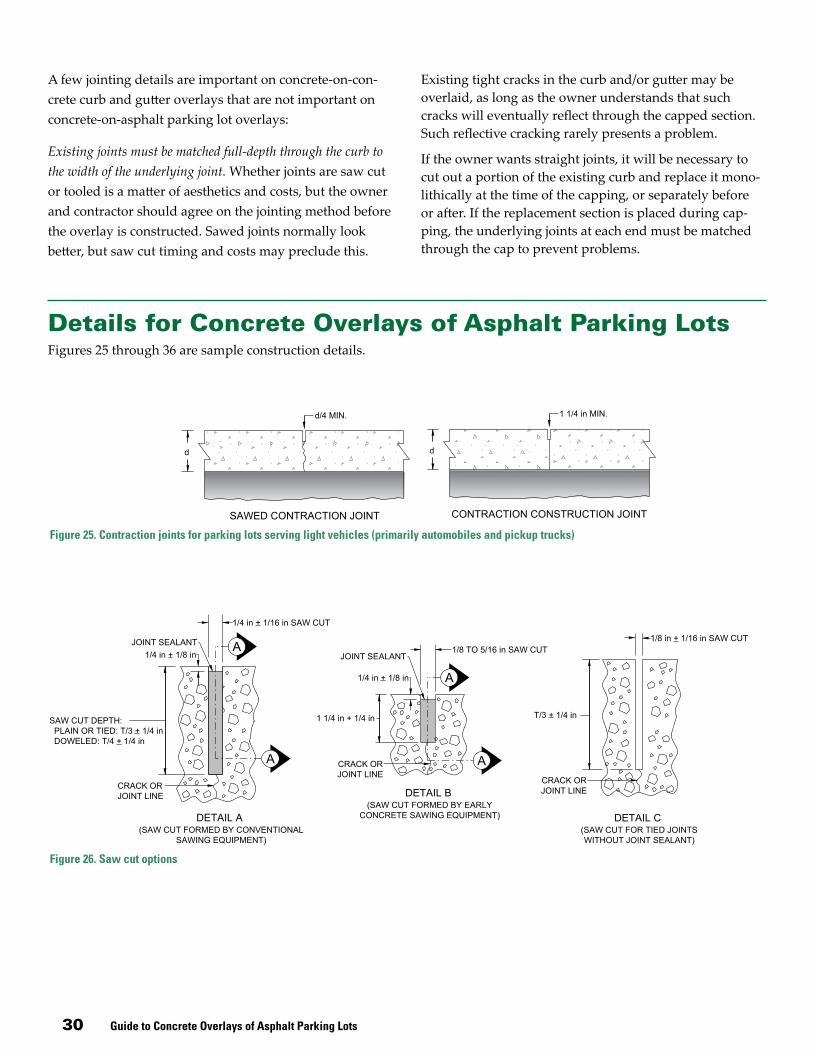
30 Guide to Concrete Overlays of Asphalt Parking Lots
A few jointing details are important on concrete-on-con-crete curb and gutter overlays that are not important on concrete-on-asphalt parking lot overlays:
Existing joints must be matched full-depth through the curb to the width of the underlying joint. Whether joints are saw cut or tooled is a matter of aesthetics and costs, but the owner and contractor should agree on the jointing method before the overlay is constructed. Sawed joints normally look better, but saw cut timing and costs may preclude this.
Existing tight cracks in the curb and/or gutter may be overlaid, as long as the owner understands that such cracks will eventually reflect through the capped section. Such reflective cracking rarely presents a problem.
If the owner wants straight joints, it will be necessary to cut out a portion of the existing curb and replace it mono-lithically at the time of the capping, or separately before or after. If the replacement section is placed during cap-ping, the underlying joints at each end must be matched through the cap to prevent problems.
Details for Concrete Overlays of Asphalt Parking LotsFigures 25 through 36 are sample construction details.
Figure 25. Contraction joints for parking lots serving light vehicles (primarily automobiles and pickup trucks)
Figure 26. Saw cut options

Guide to Concrete Overlays of Asphalt Parking Lots 31
Figure 27. Optional curb details
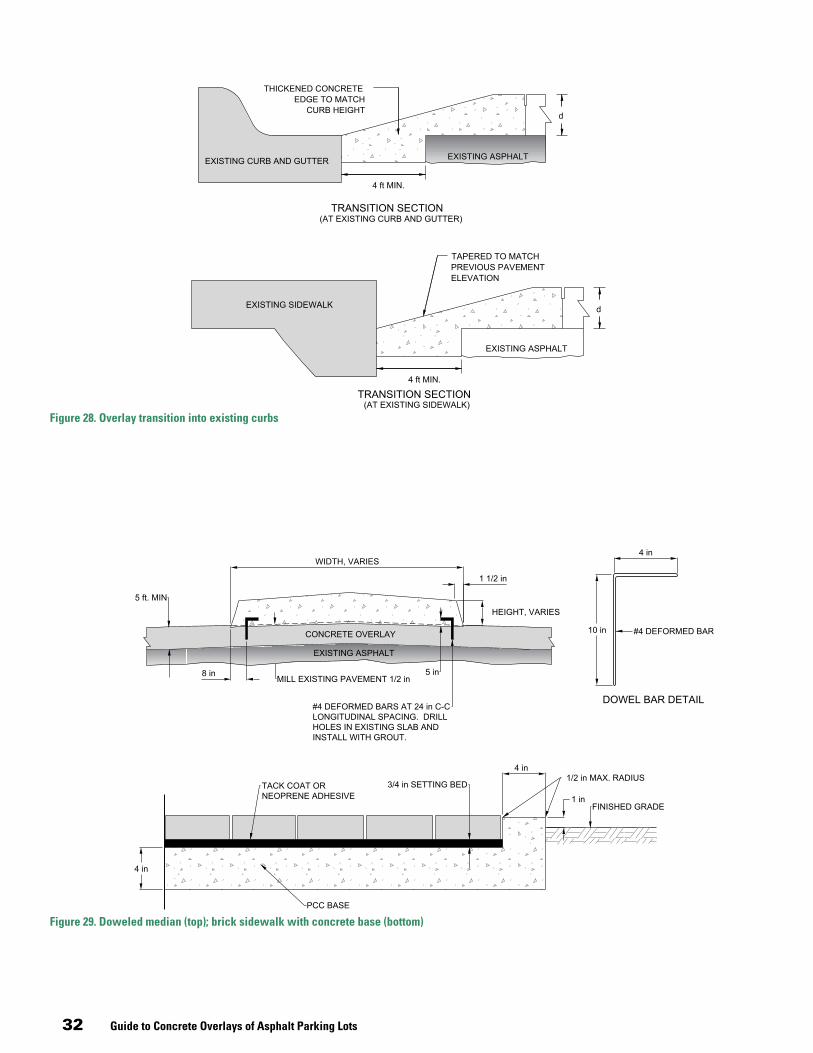
32 Guide to Concrete Overlays of Asphalt Parking Lots
Figure 29. Doweled median (top); brick sidewalk with concrete base (bottom)
Figure 28. Overlay transition into existing curbs
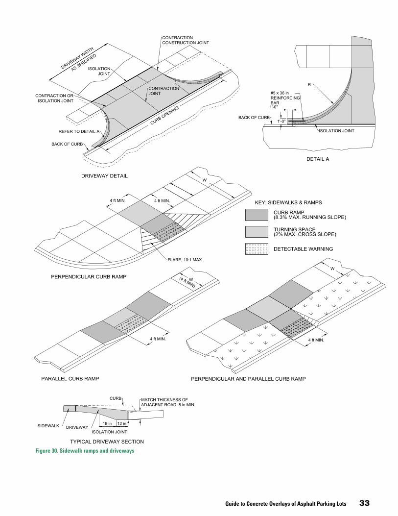
Guide to Concrete Overlays of Asphalt Parking Lots 33
Figure 30. Sidewalk ramps and driveways
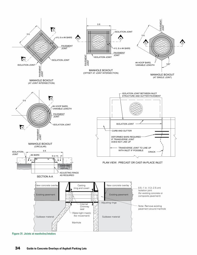
34 Guide to Concrete Overlays of Asphalt Parking Lots
Figure 31. Joints at manholes/intakes

Guide to Concrete Overlays of Asphalt Parking Lots 35
Figure 32. Typical access way/truck lane
Figure 33. Isolation joint details

36 Guide to Concrete Overlays of Asphalt Parking Lots
Figure 34. Dowel or thickened edge joints
Figure 35. Example plate dowel construction joint
Figure 36. Example plate dowel contraction joint

Guide to Concrete Overlays of Asphalt Parking Lots 37
Key Points: Materials and ConstructionTable 9 (pages 37–41) summarizes key topics related to materials and mixtures, pre-overlay repairs, and construction.
Topic Objectives/Expectations Considerations/Limitations
MATERIALS AND MIXES
Cement Hydraulic cements include portland cement and blended cements that contain SCMs. Type I or Type II cements are the most common cements in concrete overlays of asphalt parking lots. Type I is a general purpose cement suitable for all uses where special properties are not required. Some-times Type II cements are used to help protect the concrete against moderate sulfate attack.
The use of Type II cement in concrete must be accompanied by the use of a low water-to-cementitious-materials (water/cm) ratio and low permeability to control sulfate attack. Blended cements with moderate sulfate (MS) resistance or high sulfate (HS) resis-tance may also be used in sulfate-exposed environments.
Slag Cement (Type IS)
Slag cement can effectively reduce alkili-silicate reac-tion (ASR) expansion, increase long-term strength, reduce permeability, reduce concrete temperature, and slow hydration.
Because slag cement may reduce the rates of early strength gain and hydration, some cold-weather states recommend restricting the amount of slag cement used in mixtures for projects construct-ed in cold weather.
Fly Ash
Type C
Type F
Fly ash will increase long-term strength, reduce perme-ability, and reduce set temperature. Some fly ash can slow hydration on accelerated construction projects.
Because fly ash can reduce the rates of early strength gain and hydration, some cold-weather states recommend restrictions on the use of fly ash in cold weather.
Type C fly ash will increase long-term strength and reduce water demand and permeability. This may or may not slow hydration or reduce ASR expansion.
Type C fly ash can affect strength gain. Too high a dosage may increase the risk of rapid stiffening and/or damage due to salt scaling. Mixtures must be tested to determine how much Type C fly ash is required to reduce ASR-related expansion.
Type F fly ash will increase long-term strength and reduce permeability. It will also slow hydration and help reduce ASR expansion.
Type F fly ash delays setting and reduces rate of strength gain. High loss-on-ignition affects air entrainment. Type F is generally effective at reducing ASR-related expansion. Availability may be limited.
Chemical Admixtures
Chemical admixtures are added to the concrete mixtures to modify certain concrete properties such as strength. Add-ing chemical admixtures can achieve these properties more efficiently than adjusting other mixture ingredients such as the type of cement. Combined admixtures that contain both water reducers and accelerators are available.
The effects of set-modifying admixtures on other properties of concrete, like shrinkage, may not be predictable. Therefore, ac-ceptance tests of set modifiers should be made with job materials under anticipated job conditions. Compatibility of the admixtures with other ingredients should be tested for potential constructabil-ity problems.
Water Reducers Water reducers lower water demand in order to reduce
paste content (lowers w/cm ratio) to help minimize shrink-age, temperature, and cracking without sacrificing work-ability. Water reducing admixtures can also increase early strength gain by lowering the quantity of water necessary for cement hydration (by as much as 10%). Typical recom-mended w/cm ratios are ≤ 0.45.
Confirm that water reducers are compatible with other chemical admixtures and cements, particularly under harsh environmental conditions. Confirmed laboratory testing is essential to determine if the admixtures will develop the desirable properties. Types F and G high-range water reducers are not normally used in park-ing lot pavements because of their high cost and the difficulty of controlling the mixture’s slump range required for slipform paving. Overdoses of water reducers, particularly normal-range products, may severely retard or prevent setting.
Accelerators Accelerating admixtures are used to increase the rate of strength development of concrete at an early age, includ-ing in cold weather. It is important to test both fresh and hardened concrete properties before using accelerators in bonded overlays.
Long-term strength may be lower. Excess acceleration may result in cracking before finishing and/or saw cutting can be completed. Care must be exercised in using accelerators in thin overlays so as not to cause early shrinkage, cracking, and high curling and warping.
Air Entrainment
Concrete in parking lots subject to freezing and thawing should be air entrained. Air entrainment will dramatically improve the durability of concrete exposed to moisture dur-ing cycles of freezing/thawing and improves resistance to surface scaling caused by chemical deicers. It also tends to improve the workability of concrete mixtures, reduce water demand, and decrease mixture segregation and bleeding.
Compatibility with other admixtures must be checked. For about every 1% of air entrained, about 5% of concrete compressive strength is lost. When loss of air through the paver approaches 3%, the air system (quantity and distribution) may not be accept-able, and the hardened air-void sample should be checked. The minimum air content after placement should be 5%.
Retarders Retarders are useful in extending set times. They increase
the bleeding rate and capacity and may be accompanied by some reduction in early-age strength gain (one to three days) but higher later strengths.
Retarders can lengthen the time window that a concrete slab may be vulnerable to plastic shrinkage cracking and rain damage. Retarders are sometimes used to try to decrease slump loss and extend workability. This application is incorrect because, under certain conditions, the opposite results can occur.
Table 9. Key Points for Materials and Construction of Concrete Overlays on Asphalt Parking Lots
38 Guide to Concrete Overlays of Asphalt Parking Lots
Topic Objectives/Expectations Considerations/Limitations
MATERIALS AND MIXES, continued
Aggregates
Aggregates selected for paving should be durable for freezing-and-thawing exposures, and should not con-tain porous cherts in excess of applicable specification limits. Coarse aggregates meeting ASTM C 33 or local highway department specifications for concrete paving normally provide acceptable in-service performance (refer to ACI 221R for additional guidance). It is critical that aggregate be well graded (that is, there should be a wide range of aggregate sizes). Well-graded aggregate has less space between aggregate particles, therefore reducing paste demand without loss of work-ability. Reduced paste content reduces shrinkage and early age cracking, particularly with accelerated mixes.
Aggregate is subject to varying conditions in storage and handling. At the very least, these changes should be anticipated and accommodations made to adjust the water content in the mixture as necessary. Ideally, real-time monitoring of the aggre-gate moisture content would allow for “on the fly” changes. In most circumstances, a well regulated sampling program using rapid evaluation equipment will improve this component of the process considerably. Potential alkali-silica reactivity (ASR) and D-cracking have become important durability considerations for aggregates. Aggregates that test positive for potential ASR should only be used with mitigation procedures. These include the use of low-alkali cements, pozzolans, slag cement, and blended cements that have proven effectiveness in ASR test programs. The best evidence of an aggregate’s potential ASR properties is its service record for 10 or more years per ACI 221R). Aggregates tested positive for D-cracking should not be used.
Fibers Although not typically required for concrete overlays, consideration should be given to using fibers for thin concrete overlays in parking lots. Fibers improve the toughness of the concrete overlay and its resistance to plastic and dry shrinkage cracking, particularly with bonded overlays. Fibers also can increase the flexural strength of the concrete.
Inclusion of fibers in the mixture must be accomplished so as to prevent their balling into clumps. In some cases, water-soluble bags are added to the final batch. A staging area may be needed with adequate capacity to avoid a queue. In other cases, individual (bulk) fibers may be introduced into the mixture; in this situation, a blower appropriate to the application should be considered.
Mixing and Batching Batching of concrete used in concrete overlays for parking lots is usually no different from conventional concrete paving with ready-mix applications. Concrete for parking lot pavements should be batched, mixed, and delivered in accordance with ASTM C 94/C 94M or C 685/C 685M. Components of the mixture should follow the requirements contained in other appropriate ASTM specifications. Proportioning concrete by the methods used in ACI 211.1 will help to ensure that the concrete will provide the required strength, long-term durability, economy, and workability envisioned by the parking lot owner, designer, and contractor. ACI 301 may also provide useful guidance. ACI 304R contains guidance on batching, mixing, and placing.
The proportions for the concrete can be established on the basis of laboratory trial batches. For most small parking lot projects, the effort and expense required to establish proportions by labo-ratory trials may not be justified if commercial concrete with the requisite performance history is available. Commercial mixtures proportioned and approved for use in state, city, or county pav-ing will usually be adequate for parking lots. Concrete producers normally have standard mixtures with performance records that are appropriate for parking lot projects.
Capacity Having adequate batching capacity is an important link in the process of constructing concrete overlays. Both mixing time and the availability of transport equipment should be balanced along with cost.
Contingency plans should include preparation for rapid responses (repairs) of the more common equipment malfunctions.
Consistency During batching, consistency and uniformity are criti-cal. Adequate mixing time should be balanced with the need for increased production rates.
Bonded concrete overlays are particularly vulnerable to changes in material properties due to their commonly thin sections.
Table 9. Key Points for Materials and Construction of Concrete Overlays on Asphalt Parking Lots, continued

Guide to Concrete Overlays of Asphalt Parking Lots 39
Topic Objectives/Expectations Considerations/Limitations
PRE-OVERLAY REPAIRS AND SURFACE PREPARATION
Spot Repairs
Some projects will require spot repairs to the existing asphalt pavement. (If extensive repairs are required, the parking lot is not a good candidate for an overlay.) Spot areas with potholes, localized, moderate-to-severe alligator cracking, or loss of base/subgrade support may require partial or full-depth repairs to achieve the desired load-carrying capacity and long-term durability.
Full-depth repairs are effective at correcting many differ-ent types of localized distress.
Quality of spot repairs will often be critical to the success-ful performance of the concrete overlay system.
Asphalt patches do not bond well with concrete overlays, so con-crete patches are recommended. Patching should be completed after any required milling.
Whether a concrete patch is placed separately or placed at the same time as the overlay (i.e., in one paving operation), the result is a spot section of thicker concrete. This thicker section of concrete will move differently from the adjacent asphalt, so no single overlay panel should be over both asphalt pavement and the concrete patch. This will require the normal jointing pattern of the overlay to be adjusted to isolate the section over the concrete patch.
The effectiveness of a repair is dependent on the proper repair size. Most parking lot repairs are a minimum length of 4 to 6 ft (1.2 to 1.8 m).
Salvaging the existing dowel system is not recommended.
All delaminated asphalt should be removed, and no asphalt around the repair boundaries should be damaged.
Crack Repairs Concrete should span most asphalt longitudinal and trans-verse cracks during construction of the bonded overlay. In isolated areas with a high number of wide transverse cracks such as thermal cracks, the cracks can either be bridged with the overlay or cleaned and filled prior to the overlay.
Filling old cracks with fly ash slurry, concrete grout, or other ap-propriate material is necessary only for cracks that have an opening greater than the maximum size aggregate used in the overlay.
Milling
The main objectives of milling are to (1) remove significant surface distortions that contain soft asphaltic material, which would result in an inadequate bonding surface; (2) reduce high spots to help ensure minimum overlay depth and reduce the quantity of concrete needed to fill low spots; and (3) match curb or adjacent structure elevations. Milling may also be considered to roughen the surface and enhance bonding.
In general, milling of asphalt should be minimized because it results in loss of structural support. The objective is not to obtain a perfect cross section or to completely remove ruts. (Heavy rutting and/or fractured cracking are typically caused by truck traffic. In truck traffic routes separate from typical light traffic parking areas, a separate overlay of increased thickness should be placed.)
Most surface distresses can be removed through milling. Milling should be used where surface distortions are 1.5 in. (38 mm) or greater.
The amount of asphalt removed depends on the types and severity of distresses and the thickness of the asphalt. It is important to ensure the milling depth does not compromise the bonding effectiveness of asphalt tack lines between existing asphalt lifts. Therefore, milling should remove asphalt to the nearest tack line. A minimum of 2 in. (38 to 50 mm) of asphalt should remain after milling and at least 1 in. from the tack line.
An adequate layer of asphalt is required to prevent delamination, thus ensuring that the asphalt will function as a load-carrying portion of the composite pavement (and not as a separation layer or shear plane, as in an unbonded overlay).
While the milling machine is on site, the pavement surface should be inspected to determine if additional milling is required.
After milling, the surface should be inspected for isolated pockets of deterioration that require further repairs. In spot areas that still have some loss of structural integrity, the poor asphalt should be removed and the overlay thickness should be increased.
Retrofitted Edge Drains
A good candidate project for retrofitted edge drains is a parking lot that is showing early signs of moisture damage and is relatively young (i.e., less than 10 years old). Many studies have concluded that retrofitted edge drains are not effective at prolonging the service life of pavements that have already experienced significant moisture-related deterioration (Wells and Wiley 1987; Young 1990; VDOT 1990).
When placing corrugated polyethylene pipes, extra care is required to prevent overstretching the pipes during installation. To avoid dam-age to the pipes during compaction, a minimum of 6 in. (150 mm) of cover over the drainage pipe is recommended before compacting.
Table 9. Key Points for Materials and Construction of Concrete Overlays on Asphalt Parking Lots, continued

40 Guide to Concrete Overlays of Asphalt Parking Lots
Topic Objectives/Expectations Considerations/Limitations
PRE-OVERLAY REPAIRS AND SURFACE PREPARATION, continued
Surface Preparation/ Cleaning
Following repairs, the asphalt surface needs to be cleaned to ensure adequate bonding with the new con-crete overlay, which is very important to the performance of this type of overlay. Cleaning can be accomplished by first sweeping the asphalt surface, then cleaning with compressed air. Pressure washing should be considered only when dust control is mandated or when mud has been tracked onto the milled surface.
In no case should water or moisture be allowed to stand on the asphalt pavement prior to overlay placement.
To prevent contamination, it is important to avoid a lengthy lag time between final surface cleaning and paving.
Traffic on Prepared Surface
Phasing of surface preparation operations can allow for intermediate trafficking of the surface prior to the overlay placement.
If traffic is allowed on the prepared surface prior to placing the over-lay, subsequent cleaning of the surface is required, particularly for bonded overlays, in order to remove any potential contamination.
CONSTRUCTION
Planning and Coordination
Construction of parking lots should be accomplished in compliance with adequate plans and specifications to provide a pavement that will meet the owner’s needs. Because the contractor is responsible for providing qual-ity workmanship, ACI-certified finishers and compliance with ACI 121R are recommended. This is especially im-portant on small projects that are likely to be constructed with little or no inspection.
A preconstruction conference should be conducted with the owner, designer, contractor, and subcontractors, including the concrete supplier. The objectives are to coordinate the contractors, determine the type equipment for the project, arrange for a realistic delivery rate of concrete, determine the construction sequence, arrange delivery routes for concrete trucks,* and review anticipated weather conditions. The National Ready Mixed Concrete Association offers a recommended agenda for a preconstruction conference (1999).
Staging Area The project limits should be evaluated to determine adequate staging areas. The staging areas are necessary for ready mix truck washouts, storage of equipment and materials, construction trailers, and possibly a portable concrete mixing plant.
Additional construction costs and user delays for construction under traffic must be compared to travel delays and extra mileage with detours.
Plans for Construction
A layout to permit efficient use of paving equipment, provide access for concrete delivery trucks, and ensure site drainage can expedite construction operations. The contractor and engineer should agree on joint layout and construction methods before paving begins; a drawing of joint locations and paving sequence is helpful. Locations of drainage fixtures, lighting supports, and other fixed objects should be established, with joint patterns and construction methods in mind.
Paving should be done in blocks (block placement) or in lanes (strip placement; see page 42). When strip placement is used, paving-lane widths should be in multiples of the joint spacings. The width will depend on the equipment and method selected by the contractor. Checkerboard placing is not recommended and should be avoided because it requires more time and forming materials and usually results in less consistent surface tolerances and poorer joint load transfer. See Placement of Concrete Overlays beginning on page 42.
Equipment See Equipment for Concrete Parking Lot Placement (page 42)
Concrete Placement
When the surface temperature of the asphalt is at or above 120°F, surface watering can be used to reduce the temperature and minimize the chance of fast-set shrink-age cracking.
No standing water should remain on the surface at the time the overlay is placed. Water trapped in the milled surface can be blown off with compressed air.
Paving is accomplished using either conventional fixed-form or slipform construction, depending on the size of the project and any geometric constraints. Because of variations in the concrete thickness, the concrete mate-rial is paid for on a cubic-yard basis. Placement is paid on a square-yard basis.
The concrete should be deposited as uniformly as possible ahead of the paving equipment, and as close to its final position as possible, so as to require minimum rehandling. The concrete should be consolidat-ed along the faces of the forms and struck off to the required elevation and cross section. If slipform equipment is used, the concrete should be of the consistency necessary to prevent noticeable edge slump.
Workability is an important consideration in selecting concrete for a parking lot paving project. Slump for slipform paving is usually 1½ in. or less. Concrete to be placed by hand or with vibrating screeds will require a higher slump, generally 4 in. or less. Water content, aggregate gradation, admixtures, and air content are all factors that affect workability. The recommended w/cm ratio is 0.45 or less. The maximum aggregate size should be no greater than one-third the thickness of the slab.
*When concrete is supplied to a project from more than one batch plant, the concrete should be placed in the order the trucks were batched, not the order in which they arrived at the site. This helps prevent variable bleeding and setting and subsequent finishing sequence difficulties. Consistency of the concrete mix is very important to the production and quality of the finishing process.
Table 9. Key Points for Materials and Construction of Concrete Overlays on Asphalt Parking Lots, continued

Guide to Concrete Overlays of Asphalt Parking Lots 41
Topic Objectives/Expectations Considerations/Limitations
CONSTRUCTION, continued
Finishing and Texturing
The surface should be finished no more than necessary to remove irregularities. Immediately following strike-off, the surface should be leveled with a bullfloat or a scraping straightedge. All edges, tooled joints, and isolation joints should be rounded to the specified radius with appropri-ate tools. The use of hand or power floats and trowels is not necessary and is not recommend, as this can result in scaling.
As soon as the finished concrete has set sufficiently to maintain a texture and no bleed water remains on the surface, the sur-face can be dragged with a short length of damp burlap or other material such as synthetic turf carpeting. Drags are sometimes attached to paving machines or screeds. As an alternative, the surface can be broomed to develop a skid-resistant surface and uniform appearance.
Curing Curing is arguably more critical for concrete overlays than for most other paving projects. The relatively thin nature of overlays increases their surface area with respect to their volume. The result is more susceptibility to excess moisture loss and resulting distresses. Improper coating can result in plastic shrinkage cracking, full-depth shrink-age cracking, wide joints, and surface distresses.
Because of the wide area being paved, the proper application of curing compound on a parking lot overlay is more difficult than on a roadway overlay. Therefore, care must be exercised in making sure a uniform and thorough coating of curing compound is applied, especially in cold weather.
The application of white-pigmented membrane-forming curing compounds meeting ASTM C 309 or C 1315 (Type II) require-ments should follow normal curing procedures as recommend-ed by the manufacturer. After finishing and texturing operations have been completed, and immediately after free water has evaporated, the surface of the slab and any exposed edges should be uniformly coated with a high-solids curing compound. For hot/cold weather protection, see ACI 330R-08. In general, within 30 minutes of placing the overlay, curing compound should be applied at twice the standard rate. The finished prod-uct should appear as a uniformly painted solid white surface, with no gray areas, and with the vertical faces along the edges of the overlay thoroughly coated.
Special Curing For overlays that require a very fast opening to traffic and are relatively short in length, special curing in addition to curing compound is used. It normally consists of insulat-ing blankets that provide a uniform temperature environ-ment for the concrete.
Special curing is normally not required in summer months for accelerated construction, but it does have an effect on strength gain when air temperatures are less than 65°F (19°C), and it has a pronounced effect when temperatures are less than 55°F (13°C) in colder months.
Jointing Jointing concrete overlays is a critical operation. The thin overlay lift (compared to a new pavement) will often gain stresses rapidly and thus require accelerated sawing. Sometimes the need for accelerated sawing is underestimated and sawing operations fall too far behind the paver. The contractor should be prepared with the proper type and number of saws. In the case of jointing, redundancy in equipment is important.
The timing of the saw cutting should be done to balance the po-tential for uncontrolled cracking with the potential for excessive joint spalling during sawing. Bonded concrete overlays require the most effective sawing operations to prevent overlay failures. For overlays on asphalt, particularly when there is wheel rutting in the asphalt, the depth of the saw cut should be increased to account for the extra depth in the wheel rut areas.
Fillets Fillets provide a level of safety precaution at drop-offs. Placement of form fillets may require sawing.
Maturity Method for Strength Testing/ Opening
Utilizing maturity testing for accelerated construction pro-vides a reliable technique for estimating in-place strength and thus the time of opening. The temperatures measured as part of maturity testing have shown to be effective in identifying potential changes to the concrete mixture. Maturity testing provides a reliable technique for continu-ous monitoring of concrete strength gain. Most important, maturity testing enables any pavement to be opened to traffic as soon as it meets strength criteria. Concrete maturity concepts are being applied by 32 states.
Development of a maturity curve is an important element of ma-turity testing. As construction proceeds on a project, validation of the maturity curve may be necessary when changes occur in mixture constituents, material sources, mixture operations, and water/cm ratios. Also, some states set an automatic validation criterion based on a time period. Most states using a maturity curve have established validation criteria, which allows some flexibility in mixture changes without the development of a new maturity curve.
Opening Strength There is not a simple field test to measure the strength of the concrete-asphalt bond. Instead, a value for opening strength of the concrete of 420 psi flexural (2,500 psi com-pressive) to 480 psi flexural (3,000 psi compressive) seems to be reasonable.
An additional consideration for accelerated construction is to encourage bond via milling of the existing asphalt surface. If shear failures do occur, they will likely occur in the asphalt, since concrete shear strength is greater than asphalt shear strength.
Table 9. Key Points for Materials and Construction of Concrete Overlays on Asphalt Parking Lots, continued

42 Guide to Concrete Overlays of Asphalt Parking Lots
Placement of Concrete OverlaysDuring the last few years, the use of mechanical screeds for the placement and consolidation of concrete overlays on asphalt parking lots has increased. Construction prac-tices for thin concrete overlays frequently favor the use of mechanical screeds such as laser-guided screeds, since the concrete area to be paved is much wider in parking lots than in street or highway paving. However, slipform pav-ers are still used for high-production paving in parking areas. Two types of placement are recommended: block placement and strip placement.
Block placementWhen conditions allow, large block placements, as illustrated in Figure 37, provide the most efficient method of construction for large areas of paving. The reduced forming combined with the efficiencies of scale make this the most common placement technique for parking lots.
Strip placementIn some cases, the rate of concrete supply, weather condi-tions, texture required, or equipment available makes long alternating strips the most efficient placement method. Strip placement, as shown in Figure 38, improves access on both sides to complete finishing, texturing, and cur-ing operations. Construction joints can be slipformed or formed with bulkheads. The width of placement is usually dictated by the equipment, but widths should be multi-ples of the specified joint spacing. Wider strip placements often require the introduction of intermediate contraction joints. Intermediate longitudinal and transverse contrac-tion joints can be installed at the specified joint spacing intervals.
Equipment for Concrete Parking Lot PlacementThe placement of the concrete is outlined in the previous section. The majority of the equipment used to place con-crete overlays in parking lots has to do with consolidation and screening the concrete into final form. The majority of screeds used today (mechanical, roller, laser-guided, and truss screeds) are equipment with vibrators that also consolidate the concrete with the screed striking off the
concrete to the desired grade and shape. The discussion in this section mainly concentrates on the many types of screeds based on the size of the project. The information contained herein is taken from ACI 330 (draft) Guide for Design and Construction of Concrete Paving for Heavy Industrial and Tracking Facilities.
Figure 37. Block placement
Contraction joint
Construction joint
Block paved first
Block paved second
Figure 38. Strip placement
Contraction joint
Construction joint
Lanes paved first
Lanes paved second

Guide to Concrete Overlays of Asphalt Parking Lots 43
Hand/wet screedingAlthough screeding of parking lot pavements is gener-ally accomplished with a mechanical piece of equipment such as a laser-guided screed, slipform paving machine, or vibratory screed machine supported by edge forms, some smaller areas of a parking lot are best suited to hand screeding. Where surface tolerances are not critical, hand strike-off tools can be used with properly set grade stakes and “wet” screeds. Hollow magnesium or solid wood straightedges are commonly used for hand-screeding concrete (Figure 39). The length of these straightedges var-ies up to 20 ft. Straightedge cross-sectional dimensions are generally 1- to 2-in. (25- to 50-mm) wide by 4- to 6-in. (100- to 150-mm) deep. When non-vibrating screeding devices are used, hand-held gasoline or electric powered vibrators are used before screeding to ensure proper consolidation (Figure 40).
Handheld vibratory screedHandheld vibratory screeds have been developed to ease the process of hand screeding. They are comprised of a straightedge with a generally wider contact area, handles to allow workers to stand in a more upright position, and a vibratory attachment to induce surface vibration to aid in the screeding and leveling process. See Figure 41. Tools specifically made for screeding, such as these or hollow magnesium straightedges, are preferred over randomly selected lumber, which can warp and twist during con-struction. Selection of the length and type of screed device to be used is somewhat dependent on the placement con-figuration. The maximum practical width of screed strips for hand screeding is approximately 16 ft. Therefore, the length of the hand screeding device should not be longer than 18 ft (5 m) and should overlap previously placed strips of wet concrete a minimum of 2 ft (600 mm). Where strict elevation tolerances apply, it is wise to limit the width of screed strips and to overlap further. This method is generally used in irregular areas and on slabs less than 10,000 sq ft.
Roller screedsRoller screeds knock down, strike off, and can provide mild vibration or no vibration. See Figures 42, 43, and 44. They can rotate at varying rates up to several hundred revolutions per minute, as required by the consistency of the concrete mixture. The direction of rotation of the rollers on the screed is opposite to the screed’s direction of movement. These screeds are most suitable for concrete
Figure 39. “Striking off” with hand wet screed
Figure 40. Concrete vibrator
Figure 41. Mechanical vibrating floating screed
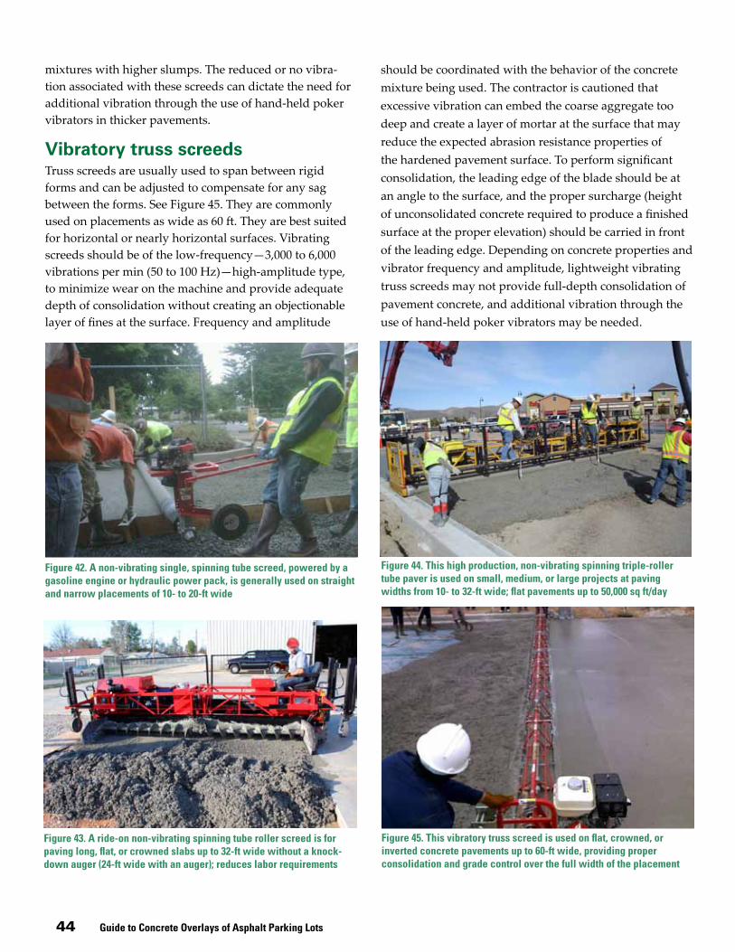
44 Guide to Concrete Overlays of Asphalt Parking Lots
mixtures with higher slumps. The reduced or no vibra-tion associated with these screeds can dictate the need for additional vibration through the use of hand-held poker vibrators in thicker pavements.
Vibratory truss screedsTruss screeds are usually used to span between rigid forms and can be adjusted to compensate for any sag between the forms. See Figure 45. They are commonly used on placements as wide as 60 ft. They are best suited for horizontal or nearly horizontal surfaces. Vibrating screeds should be of the low-frequency—3,000 to 6,000 vibrations per min (50 to 100 Hz)—high-amplitude type, to minimize wear on the machine and provide adequate depth of consolidation without creating an objectionable layer of fines at the surface. Frequency and amplitude
Figure 42. A non-vibrating single, spinning tube screed, powered by a gasoline engine or hydraulic power pack, is generally used on straight and narrow placements of 10- to 20-ft wide
Figure 43. A ride-on non-vibrating spinning tube roller screed is for paving long, flat, or crowned slabs up to 32-ft wide without a knock-down auger (24-ft wide with an auger); reduces labor requirements
Figure 44. This high production, non-vibrating spinning triple-roller tube paver is used on small, medium, or large projects at paving widths from 10- to 32-ft wide; flat pavements up to 50,000 sq ft/day
Figure 45. This vibratory truss screed is used on flat, crowned, or inverted concrete pavements up to 60-ft wide, providing proper consolidation and grade control over the full width of the placement
should be coordinated with the behavior of the concrete mixture being used. The contractor is cautioned that excessive vibration can embed the coarse aggregate too deep and create a layer of mortar at the surface that may reduce the expected abrasion resistance properties of the hardened pavement surface. To perform significant consolidation, the leading edge of the blade should be at an angle to the surface, and the proper surcharge (height of unconsolidated concrete required to produce a finished surface at the proper elevation) should be carried in front of the leading edge. Depending on concrete properties and vibrator frequency and amplitude, lightweight vibrating truss screeds may not provide full-depth consolidation of pavement concrete, and additional vibration through the use of hand-held poker vibrators may be needed.

Guide to Concrete Overlays of Asphalt Parking Lots 45
Laser-guided screedsLaser-guided screeds can be used to consolidate and strike off concrete to the proper grade and slope with great effi-ciency. Concrete can be spread in front of the laser-guided screed using pumps or conveyors or by tailgating directly from concrete trucks. See Figures 46 and 47. Tailgating is the most efficient method, but additional labor may be required during placing operations to repair any rutting or pumping of subgrades and subbases caused by the concrete trucks and screed machine.
Laser-guided screeds are useful in large block pavement placements, but the need to install dowel basket assem-blies on-the-fly requires a dowel basket assembly design that provides for some misalignment and a larger instal-lation tolerance. The intended construction method and dowel basket design should be discussed and agreed upon at the pre-bid conference. Use of a pump or belt-conveyor is recommended for all placements with rebar because subgrades cannot be repaired during placement.
Slipform pavingMechanical paving equipment can be used to slipform low-slump concrete to eliminate the need for fixed forms. Slipform paving is well suited to long access roads or roadway type paving between different facilities or areas of paving within a facility. See Figure 48.
Slipform paving equipment is designed to spread, con-solidate, and strike off the concrete in a single pass. This type of equipment performs best when operated in a continuous and steady forward movement. All delivery and spreading of concrete should be coordinated so as to provide uniform progress without frequent machine stop-ping and starting. Imperfections in the surface tolerances should be rectified with the use of highway straightedges behind the placing and slipforming process. Coordina-tion with the concrete supplier is especially important for timely delivery of adequate quantities of concrete of uniform low slump.
If slipform paving equipment is used, it is important that the concrete be of a suitable consistency to prevent exces-sive edge slump after the paving equipment has passed. When the slipform paver is to ride on the edge of a new concrete pavement, the concrete strengths should be great-er than 2,000 psi (14 MPa), which can impact some sched-ules. Stringlines or other means for setting grade should be checked frequently during the slipforming process.
Figure 47. This walk-behind laser-guided screed will pave flat, crowned, or inverted pavements with 3D Profile Package installed; typically used to reach places larger machines cannot
Figure 48. The slipform paver is used for high production paving with-out using side forms, following a string line or GPS to maintain proper grade and steering; typically used when paving over 50,000 sq ft of pavement per day
Figure 46. This ride-on boom style laser-guided screed will pave flat, crowned, or inverted pavements with 3D Profile Package installed; typically used when long wide areas of 20,000 to 50,000 sq ft to mini-mize the amount of time setting forms

46 Guide to Concrete Overlays of Asphalt Parking Lots
Sawing concrete overlaysThe majority of sawing of concrete overlays is the estab-lishment of contraction joints. Saw cutting is to create weakened planes in the pavement at pre-selected loca-tions to establish the location and appearance of shrinkage crack formation. Timing of sawing operations will vary with the type of sawing equipment and the concrete’s rate of hydration. Since concrete overlays over asphalt can be as thin as 3 in., the surface-to-volume ratio is high and the concrete can set rather quickly compared to full-depth concrete. Therefore, it is very important to have an ad-equate number of saws on site to keep up with placement and curing. Sawed joints should be cut as early as pos-sible to prevent random cracking in the slab or cracking in front of the saw. However, sawing too early can cause edge spalling along the saw cut. Sawing should never be delayed until the next day unless there is an extreme delay in set time of the concrete mixture. Conventional saw cuts should be T/4–T/3 deep, and if the joints are not to be sealed, a ⅛-in. wide saw cut is preferred. If the joints are to be sealed, they should be ¼-in. wide.
The following three types of tools can be used for sawing joints:• Conventional wet-cut (water-injection) saws• Conventional dry-cut saws• Early-entry dry-cut saws
Conventional sawsConventional saws do not have skid plates, are heavier than early-entry saws, and require that the concrete gain more strength before sawing, causing sawing opera-tions to be delayed. See Figure 49. Joints produced using conventional saws are commonly made within three to four hours after finishing in hot weather, and later in cold weather. Conventional wet-cut saws are gasoline pow-ered and, with the proper blades, are capable of cutting to depths of up to 12 in. (300 mm) or more.
Early-entry sawsEarly-entry saws are lighter than conventional saws and are normally used when earlier sawing is desired. See Fig-ure 50. These lighter saws require less concrete strength to support their weight, allowing them on the pavement sooner. As a result, joints can be cut before drying shrink-age stresses, which initiate cracking, develop in the con-crete. The original early-entry saws could cut to a depth of only 1 to 2 in., but saws that can cut up to 3 in. are now commonly available. On some projects, early-entry saw cuts may need to be re-sawed at a later date to the speci-fied depth and width to receive specified joint sealants.
Figure 49. Conventional joint saw
Figure 50. Early-entry saw, which enables sawing within one to two hours of finishing and before final set to minimize random cracking
Sawing should begin as soon as the concrete has hardened sufficiently to support the weight of the saw and to avoid raveling of the coarse aggregate. This timing will typically vary from one hour after finishing in hot weather, to four hours after finishing in cold weather. Some night sawing may be required, depending on the contractor’s schedule.
Early-entry dry-cut saws use diamond-impregnated blades and a skid plate that helps prevent spalling. Timely changing of skid plates is necessary to effectively control spalling. It is best to change skid plates in accordance with manufacturers’ recommendations. Edge spalling along early-entry joints can also be minimized by using the cor-rect early-entry blade for the type of aggregate(s) in the concrete.
Guide to Concrete Overlays of Asphalt Parking Lots 47
ReferencesAASHTO. 1993. Flexible Pavement Structural Design (http://www.pavementinteractive.org/article/1993-aashto-flexible-pavement-structural-design/l accessed October 2012)
ACPA. 1998. Whitetopping—State of the Practice. Publication EB210P, Skokie, IL: American Concrete Pavement Associa-tion
ACPA. 2006. Design of Concrete Pavement for City Streets. Publication IS184.02P. Skokie: IL: American Concrete Pave-ment Association
ACPA. 2012 (update). StreetPave: Structural Design Software for Street and Road Concrete Pavements (www.pavement.com/streetpave/; accessed Oct 2012)
Adrian, W., and R. Jabanputra. 2005. Influence of Pavement Reflectance on Lighting for Parking Lots. PCA R&D Serial No. 2458. Skokie, IL: Portland Cement Association
Akbari, H., and S. Menon. 2008. Global Cooling: Increasing World-wide Urban Albedos to Offset CO2. Lawrence Berkeley National Laboratory. Arthur Rosenfeld California Energy Commission. Pavement Interactive (http://pavementinter-active.org/index. php?title=Global_Cooling:_Increasing_World-wide_ Urban_Albedos_to_Offset_CO2; accessed August 2011)
Daleiden, J.F. 1998. Video Inspection of Highway Edgedrain Systems. FHWA-SA-98-044. Washington, D.C.: Federal Highway Administration
Christopher, B. R. 2000. “Maintenance of Highway Edge-drains.” NCHRP Synthesis of Highway Practice 285. Wash-ington, D.C.: Transportation Research Board
Feng, M., and J.M. Vandenbossche. 2012. “Establishing Effective Linear Temperature Gradients for Bonded Concrete Overlays on Asphalt Pavements.” TRB An-nual Meeting Compendium of Papers. Washington, D.C.: Transportation Research Board (http://amonline.trb.org/1sig9c/1sig9c/1; accessed October 2012)
Gajda, J., and M. VanGeem. 2001. A Comparison of Six Environmental Impacts of Portland Cement Concrete and Asphalt Cement Concrete Pavements. PCA R&D Serial No. 2068. Skokie, IL: Portland Cement Association
NRMCA (no year). Concrete Pavement Analyst Software. (http://my.nrmca.org/scriptcontent/BeWeb/Orders/Pro-ductDetail.cfm?pc=2PCPAS; accessed October 2012)
Packard, R.G. 1984. Thickness Design for Concrete Highway and Street Pavements. Skokie, IL: Portland Cement Association
Popovics, S. 1986. “Chemical Resistance of Portland Ce-ment Mortar and Concrete,” Corrosion and Chemical Resis-tant Masonry Materials Handbook. Park Ridge, NJ: Noyes Publications, 336
Riley, R. 2006. Modified ACPA Ultra-Thin Whitetopping Design Software
Riley, R.C., L. Titus-Glover, J. Mallela, S. Waalkes, and M. Darter. 2005. “Incorporation of Probabilistic Concepts Into Fatigue Analysis of Ultrathin Whitetopping as Devel-oped for the American Concrete Pavement Association.” Proceedings from the Best Practices in Ultra Thin and Thin Whitetopping. April 12-15, 2005. Denver, CO, 288–317
Roesler, J., A. Bordelon, A. Ioannides, M. Beyer, and D. Wang. 2008. Design and Concrete Material Requirements for Ultra-Thin Whitetopping. FHWA-ICT-08-016. UILU-ENG-2008-2003. Urbana, IL: University of Illinois at Urbana Champaign (http://ict.illinois.edu/Publications/report%20files/FHWA-ICT-08-016.pdf; accessed October 2012)
Schrader, E.K. 1987. “A Proposed Solution to Cracking Caused by Dowels,” Concrete Construction, Dec. 1987
Schrader, E.K.. 1991. “A Solution to Cracking and Stresses Caused by Dowels and Tie Bars,” Concrete International, July 1991, 40–45
Van Dam, T., and P. Taylor. 2009. Building Sustainable Pave-ments with Concrete. Ames, IA: National Concrete Pave-ment Technology Center, Iowa State University (www.cproadmap.org/publications/sustainability_briefing.pdf; accessed December 2011)
Wathne, L. 2010. “Sustainability Opportunities With Pave-ments: Are We Focusing on the Right Stuff.” Proceedings: International Conference on Sustainable Concrete Pavements: Practices, Challenges, and Directions. Sacramento, CA
Pavement Tools Consortium (no year). (Lead: University of Washington) (www.scribd.com/doc/24514783/WSDOT-Pavement-Guide#outer_page_466; accessed October 2012)
SHRP. 1993. Distress Identification Manual for the Long-Term Pavement Performance Project. SHRP-P-338. Washington, D.C.: Strategic Highway Research Program, National Research Council
AI (no year). Asphalt Pavement Distress Summary. Asphalt Institute (www.asphaltinstitute.org/public/engineering/maintenance_rehab/asphalt-pavement-distress-summary.dot; accessed October 2012)

48 Guide to Concrete Overlays of Asphalt Parking Lots

Guide to Concrete Overlays of Asphalt Parking Lots 49
On parking lots for light-weight vehicles such as automobiles and pickup trucks, the use of fiber reinforcement in a thin concrete overlay is generally not necessary to achieve a durable pavement. Most such overlays can be cost effectively designed and constructed to meet the desired design life. However, fiber reinforcement should be considered in any of the following situations:
• The asphalt parking lot has specific vertical restrictions.
• The asphalt lift is very thin (and thus may not readily bond with the concrete).
• The base thickness and/or condition is inadequate.
• The design thickness makes conventional reinforce-ment difficult to use.
• The design life needs to be increased.
• An increase in heavy-truck traffic is planned or anticipated.
During the last two decades there has been resurgence in the use of fiber reinforcement in concrete. The reason for this is that properly used, newer fiber reinforcement technology can and does contribute to the performance of thin concrete overlays of asphalt parking lot applications. Whether the use of macro fiber in concrete overlays of asphalt is warranted should be determined based on the existing asphalt pavement and base thickness and condi-tion, the owner’s desired finish, the engineer’s expected design life, and the overlay thickness. Since the thickness of concrete overlays on parking lots is relatively thin com-pared to highway applications, conventional reinforce-ment techniques are difficult to use. This is making fibers once again a consideration in concrete pavement.
Why fibers?Fiber-reinforcement in Fiber-Reinforced Concrete (FRC) increases the concrete structural integrity. FRC contains short, discrete fibers that are uniformly distributed and randomly oriented. The most common of these fibers include synthetic and steel fibers. Synthetics have played a predominant role for the last two decades as the technol-ogy has improved. Other fiber types such as glass, cellulose, and natural fibers are occasionally used, but these are relatively rare and outside the scope of this document. Characterization of the fibers with different
concrete is normally based on fiber materials, geometries, distribution, and densities.
Used in sufficient dosages, fibers help increase, in engineering terms, the “toughness” and ductility of concrete. Enhancing the toughness and ductility provides flexibility to the designer, since longer joints and/or thin-ner sections of concrete can be used. Both options can be advantageous, as they allow the designer to adjust designs to help control thickness for difficult grade problems or lower sawing costs by increasing joint spacing.
A good understanding of the several different fiber tech-nologies permits the designer to better optimize designs for specific conditions.
Sufficient fibers to increase the toughness provide an additional benefit in controlling differential slab move-ment since the fibers span the sawed joints. Plain concrete in overlay applications occasionally exhibits differential movement of the individual slabs as a result of tempera-ture, curling/warping, or load-induced movement in the underlying asphalt. As a result, joints may open up or not line up; this is principally an issue of aesthetics, but can affect performance when materials and conditions exacer-bate curling/warping. In extreme cases, joints may fault in high traffic volume areas.
Synthetic fibers have been used successfully in control-ling these problems for several years, though long-term (greater than 15 years) duration of the benefit is not yet well established, particularly for synthetic fibers. Steel fibers have been around much longer and, provided corro-sion can be kept in check or is not found to be objection-able on the surface, can be quite effective as well, but have other disadvantages compared to synthetics.
An additional benefit of fibers is their ability to hold the inevitable cracks that will occur very tightly together. These cracks can occur from a variety of causes, but the fibers render the cracks more an annoyance than an actual problem; such tight cracks will usually perform better than typical sawed joints. Good performance across cracks has been observed since fibers have been used in parking lot applications.
In the concrete plastic state, fibers also offer the advantage of increased resistance to “plastic shrinkage” cracking. This type of cracking can occur in all concrete applications
APPENDIX: Fiber-Reinforced Concrete

50 Guide to Concrete Overlays of Asphalt Parking Lots
when wind blows across the paved surface and the rate of evaporation exceeds the rate of bleed water coming to the surface of the concrete prior to set. These conditions are somewhat more common on parking concrete overlay applications due to the construction techniques.
Types of fibersThe type of fiber to be used and the recommended dos-ages for specific types are evolving fairly rapidly.
Although steel fibers have a long history in paving ap-plications, their addition to the concrete using current technology requires significant manpower, which raises cost. Steel fibers also require more care to prevent “ball-ing” of the fibers as a result of their tendency to sometimes clump together when exposed to cement and water. The latter problem can be prevented with proper charging of the mixers, which may vary with the other materials in the concrete mixture.
Synthetic fibers are generally broadly classed as macro fibers rather than micro fibers, which are also common in the industry. Generally speaking, synthetic fibers have been favored compared to steel fibers in the last few years due to ease of handling and apparently better dispersion characteristics.
The volume of fibers added to a concrete mix is expressed as a percentage of the total volume of the composite (con-crete and fibers), termed volume fraction (vf). Vf typically ranges from 0.1 to 3.0 percent. Aspect ratio (l/d) is calcu-lated by dividing fiber length (l) by its diameter (d). Fibers with a non-circular cross section use an equivalent diameter for the calculation of aspect ratio.
For current design technology the dosage of fiber, whether synthetic, steel, or some blend, is specified to produce certain behavior characteristics in the hardened concrete. These characteristics correlate with forecasts of increased performance such as flexural strength, and hence fatigue capacity is enhanced. It should be noted that the actual strength of the concrete given the current technology increases only slightly, if at all. Concrete will still crack if the load exceeds that which can be borne mechanically at its upper strength limit given the geometric properties of the section, but it will carry a much greater number of lesser loads up to that point and will continue to carry loads beyond that point. Furthermore, with the appropri-ate fiber and dosage, the crack widths will be lessened and the crack patterns will be different—typically, more tight cracks, many of which will not be visible and thus are not
a performance or aesthetic problem. Those discussions are beyond the scope of this document, but a simple analogy is to think of the concrete as being effectively stronger than that measured in a beam test; this effect varies as a function of dosage, not on weight, but by volume of fibers in the concrete mixture.
Steel fibers with a much higher density than synthetic fibers will weigh much more than synthetic fibers at the same volume in the concrete mixture; conversely, synthetic fibers at the same volume will weigh much less. However, it may also take a higher volume of one fiber compared to another to provide the same increase in pavement perfor-mance. For this reason it is important to know the type of fiber being used, the volume of the fiber needed in the mixture to produce the desired properties, and the fiber’s specific gravity. This information is essential so that the concrete producer, who batches concrete by weight rather than volume, can produce a unit volume of concrete hav-ing the appropriate behavior characteristics upon setting.
Macro synthetic fibers starting at a minimum dosage of 4 lb/cy has worked well on those parking lots where they have been used. For a typical concrete mix, this is about 0.26 percent volume. For comparison, the same volume of steel fibers would weigh about 34 lb/cy but yield some-what different characteristics in the concrete.
Fiber producers and suppliers can be of assistance in this area since, as mentioned earlier, the technology is undergoing a rapid evolutionary phase. Various blends of fiber technologies are being introduced that combine steel and synthetic fibers. Also, higher modulus synthetics are under development that may further advance the technology in the next few years. A good reference and some minimum recommended dosages for a specific class of fiber based on the current state of understanding can be found at www.dot.state.il.us/materials/syntheticfibers.pdf.
High-volume macro synthetic fiber mixtures Certain types of macro synthetic fibers in quantities greater than that mentioned earlier can provide for reduc-tion in overlay thickness, enhance post-crack flexural performance, and in some cases under high doses, actu-ally allow the concrete to become yielding in nature and to flex somewhat under loads.
Although work still needs to be done to better define the optimal amount of macro synthetic fibers to add or the optimal performance volume, based on current records of
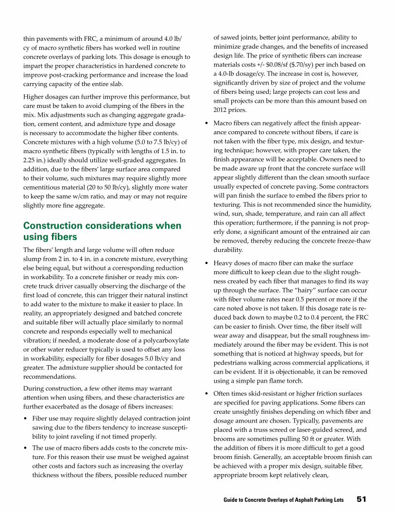
Guide to Concrete Overlays of Asphalt Parking Lots 51
thin pavements with FRC, a minimum of around 4.0 lb/cy of macro synthetic fibers has worked well in routine concrete overlays of parking lots. This dosage is enough to impart the proper characteristics in hardened concrete to improve post-cracking performance and increase the load carrying capacity of the entire slab.
Higher dosages can further improve this performance, but care must be taken to avoid clumping of the fibers in the mix. Mix adjustments such as changing aggregate grada-tion, cement content, and admixture type and dosage is necessary to accommodate the higher fiber contents. Concrete mixtures with a high volume (5.0 to 7.5 lb/cy) of macro synthetic fibers (typically with lengths of 1.5 in. to 2.25 in.) ideally should utilize well-graded aggregates. In addition, due to the fibers’ large surface area compared to their volume, such mixtures may require slightly more cementitious material (20 to 50 lb/cy), slightly more water to keep the same w/cm ratio, and may or may not require slightly more fine aggregate.
Construction considerations when using fibersThe fibers’ length and large volume will often reduce slump from 2 in. to 4 in. in a concrete mixture, everything else being equal, but without a corresponding reduction in workability. To a concrete finisher or ready mix con-crete truck driver casually observing the discharge of the first load of concrete, this can trigger their natural instinct to add water to the mixture to make it easier to place. In reality, an appropriately designed and batched concrete and suitable fiber will actually place similarly to normal concrete and responds especially well to mechanical vibration; if needed, a moderate dose of a polycarboxylate or other water reducer typically is used to offset any loss in workability, especially for fiber dosages 5.0 lb/cy and greater. The admixture supplier should be contacted for recommendations.
During construction, a few other items may warrant attention when using fibers, and these characteristics are further exacerbated as the dosage of fibers increases:
• Fiber use may require slightly delayed contraction joint sawing due to the fibers tendency to increase suscepti-bility to joint raveling if not timed properly.
• The use of macro fibers adds costs to the concrete mix-ture. For this reason their use must be weighed against other costs and factors such as increasing the overlay thickness without the fibers, possible reduced number
of sawed joints, better joint performance, ability to minimize grade changes, and the benefits of increased design life. The price of synthetic fibers can increase materials costs +/- $0.08/sf ($.70/sy) per inch based on a 4.0-lb dosage/cy. The increase in cost is, however, significantly driven by size of project and the volume of fibers being used; large projects can cost less and small projects can be more than this amount based on 2012 prices.
• Macro fibers can negatively affect the finish appear-ance compared to concrete without fibers, if care is not taken with the fiber type, mix design, and textur-ing technique; however, with proper care taken, the finish appearance will be acceptable. Owners need to be made aware up front that the concrete surface will appear slightly different than the clean smooth surface usually expected of concrete paving. Some contractors will pan finish the surface to embed the fibers prior to texturing. This is not recommended since the humidity, wind, sun, shade, temperature, and rain can all affect this operation; furthermore, if the panning is not prop-erly done, a significant amount of the entrained air can be removed, thereby reducing the concrete freeze-thaw durability.
• Heavy doses of macro fiber can make the surface more difficult to keep clean due to the slight rough-ness created by each fiber that manages to find its way up through the surface. The “hairy” surface can occur with fiber volume rates near 0.5 percent or more if the care noted above is not taken. If this dosage rate is re-duced back down to maybe 0.2 to 0.4 percent, the FRC can be easier to finish. Over time, the fiber itself will wear away and disappear, but the small roughness im-mediately around the fiber may be evident. This is not something that is noticed at highway speeds, but for pedestrians walking across commercial applications, it can be evident. If it is objectionable, it can be removed using a simple pan flame torch.
• Often times skid-resistant or higher friction surfaces are specified for paving applications. Some fibers can create unsightly finishes depending on which fiber and dosage amount are chosen. Typically, pavements are placed with a truss screed or laser-guided screed, and brooms are sometimes pulling 50 ft or greater. With the addition of fibers it is more difficult to get a good broom finish. Generally, an acceptable broom finish can be achieved with a proper mix design, suitable fiber, appropriate broom kept relatively clean,

52 Guide to Concrete Overlays of Asphalt Parking Lots
one-directional broom passes, and no “jiggling” of the broom. A small remote test area in the parking lot is a good idea so that agreement is reached on an acceptable surface in the first placement operation.
• Unless care is taken to prevent them, macro fibers may occasionally ball up and create a surface defect even if added to the ready mix discharge load under the utmost care. See Figure A-1. Some contractors drill out the “hair balls” with a 4-in. core drill to a depth of an
inch or so. This allows for the hair ball to be removed and replaced with a grout or concrete mix.
• Do not place or finish if rain is eminent since surface water will make the fibers more prominent.
• Limit the use of older types of high-range water reduc-ers (HRWR) (naphthalenes and melamines) to reduce the water-cement ratio, as they tend to bleed and exac-erbate spotty concrete setting, thereby possibly causing fibers to be more prominent. The newer HRWR (poly-carboxylates) are generally better and reduce segrega-tion effects in the mixture (both fiber and aggregate related).
• Some solvent based curing compounds will make the fibers more prominent.
Finally, know the product you are using. The use of fibers is an excellent tool for enhancing concrete overlays of existing asphalt parking lots, but the products are rapidly evolving and many owners, contractors, and produc-ers are still learning how to best apply the technology. When using macro synthetic fibers, a trial mix should be batched and placed at the ready mix producer’s facility or placed elsewhere using the ingredients and proportions approved for the project so that all know and understand what is expected. Communication with the owner, general contractor, and inspectors is important to let them know what to expect during and after construction.Figure A-1. Balling of fibers

Guide to Concrete Overlays of Asphalt Parking Lots 53
Blank end page

54 Guide to Concrete Overlays of Asphalt Parking Lots
Blank end page


