3. Post Construction Best Management Practices………………………………………………… 20
4. Contact Information ……………………………………………………………………………20
Erosion Prevention and Sediment Control Polk County, OR
Updated May 2009 1
1.0 Introduction
This brochure contains erosion prevention techniques and sediment control measures as guidance for construction operators. The focus of this brochure is to first, promote erosion prevention techniques, and second, to promote sediment control measures. Erosion prevention techniques are designed to protect soil particles from the force of rain and wind so that they will not erode. These techniques include such things as ground cover and matting. Sediment control measures are designed to capture soil particles after they have been dislodged and attempt to retain the soil particles on-site. These measures include such things as silt fences and settling basins. Both erosion prevention techniques and sediment control measures have appropriate uses; however, sediment control measures are generally considered to be less effective in preventing soil movement than erosion prevention techniques.
Erosion and sediment control during construction activities is important to maintain the quality of stormwater that enters county rivers and streams. This brochure introduces recommended measures for construction site erosion prevention and sediment control. Erosion prevention and sediment control measures are recommended for any activities where the ground surface will be disturbed with clearing, grading, fills, excavations, and other ground disturbing and construction activities. The appropriate measure(s) will depend on the characteristics of the site and type of construction.
An important concept to keep in mind when developing construction and erosion control plans is that practices which minimize the amount of disturbed land area and avoid or minimize work on steep slopes are encouraged. Such practices can cause stormwater that enters county rivers and streams to be of a higher quality and lesser quantity and allow as much topsoil as possible to be retained on the site, making revegetation and landscaping easier to establish.
This brochure was created by modifying the City of Salem’s “Erosion Prevention and Sediment Control (EPSC) Plan Technical Guidance Handbook.” This brochure has been created as a measure to implement the Polk County Stormwater Management Program.
2.0 Recommended Erosion Prevention and Sediment Control Measures
Recommended construction period erosion prevention and sediment control measures are detailed in the sections below. Erosion prevention and sediment control measures are recommended during all permitted construction and site disturbance activities and until permanent site ground covers are in place. Also, additional ground cover and/or filtration measures are recommended during the wet weather season (October 15 through April 30). All seed applications should be established prior to October 15.
The designer should keep in mind when laying out an erosion control plan that the purpose of the plan should be to maximize erosion prevention and minimize sediment transport from disturbed ground surfaces. Minimizing the area of clearing and grading, phasing of construction, and use of other methods to reduce the amount of land area disturbed will provide the greatest erosion control benefits.
Erosion Prevention and Sediment Control Polk County, OR
Updated May 2009 2
2.1 Gravel Construction Entrances
Purpose
To reduce the amount of mud, dirt, rock, etc., transported onto roads by motor vehicles or stormwater runoff by constructing a stabilized pad of gravel at approved entrances/exits to construction sites.
Conditions Where Practice Applies
At any construction site where traffic will be leaving the site and moving directly onto public roads, other paved areas, or other approved access points.
Design Criteria/Specifications
A. See Figure 1 for details.
B. Material should be clean pit run or crushed rock (1"-minus for all single family, duplex, and manufactured home sites and 2-6" for all other construction sites).
C. The gravel pad should be at least 8 inches thick and 50 feet in length. Width should be the full width of the vehicle ingress and egress area. (A 20-foot minimum pad length may be acceptable as approved for single family, duplex, and manufactured home sites.)
D. Use subgrade reinforcement geotextile under gravel pads for all but construction of a single family/duplex residence and manufactured home placement.
E. Additional gravel may have to be added periodically to maintain proper function of the pad.
F. Additional Measures: If the gravel pad does not adequately remove dirt and mud from vehicle wheels such that mud and dirt tracking is evident off site, additional measures should be taken. Such measures may include washing off wheels before vehicles leave the site (see Figure 2) or other construction techniques/work operations modifications.
G. Do not install aggregate on paved surfaces. Use curb wood ramps.
H. Install construction entrance prior to any site work.
I. Whenever possible, construct the aggregate pad on a firm compacted subgrade, Install geotextile under aggregate when subgrade is not stable or is “pumping” up into the pad.
Wheel washing should be done on the gravel pad or in an approved wheel wash structure located onsite, adjacent to and on the site interior side of the gravel pad. Wash water should be properly drained through a silt-trapping structure prior to leaving the construction site. See Figure 2 for details of a typical wheel wash structure.
Another additional measure is to construct gravel filter berms across on-site traffic wheel paths to capture and retain sediment. Berms should be 1 foot high with 3:1 side slopes, constructed of ¾- to 3-inch well-graded or crushed rock with less than 5 percent fines. Berms should be inspected regularly and accumulated sediment removed and rock added or replaced as needed. Berms should be spaced as follows:
-Every 300 feet on slopes less than 5 percent.
-Every 200 feet on slopes between 5 and 10 percent.
-Every 100 feet on slopes greater than 10 percent.
Erosion Prevention and Sediment Control Polk County, OR
Updated May 2009 3
Figure 1. Gravel Construction Entrance
Erosion Prevention and Sediment Control Polk County, OR
Updated May 2009 4
Figure 2. Wheel Wash
Erosion Prevention and Sediment Control Polk County, OR
Updated May 2009 5
2.2 Temporary Sediment Fences
Purpose
To reduce the transport of sediment from a construction site by providing a temporary physical barrier to sediment and reducing runoff velocities.
Conditions Where Practice Applies
A. Down slope of disturbed areas where runoff occurs as sheet runoff.
B. At the toe of soil or material stock piles.
C. Along the contours of large disturbed areas at intervals as follows: slopes less than 10%, every 300 feet; slopes between 10% and 14%, every 150 feet; slopes between 15% and 19%, every 100 feet; slopes between 20% and 29%, every 50 feet; and slopes above 30%, every 25 feet.
D. At grade breaks exceeding 20 percent.
E. Following discharge from a sediment trap or pond.
F. Sediment fences should not be installed across streams.
Design Criteria/Specifications
A. See Figure 3 for details.
B. Maximum sheet or overland flow path length to sediment fence at the intervals in Subsection C, immediately above.
C. Selection of filter fabric tensile and bursting strength depends on the slope characteristics. The use of standard or heavy duty filter fabric (woven polypropylene sediment fence fabric) should meet manufacturer’s design standards. Synthetic filter fabric should contain ultraviolet ray inhibitors and stabilizers to provide a minimum of 6 months of expected usable construction life at a temperature range of 0 degrees to 120 degrees Fahrenheit. Selection should be based on standard engineering principles for design.
D. Standard or heavy duty filter fabric fence should have manufactured stitched loops for 2"x 2" post installation. Stitched loops should be installed on the up-hill side of the sloped area, with posts spaced a maximum of 6 feet apart.
E. Filter fabric fence should have a minimum vertical burial of 6 inches. All excavated material from filter fabric fence installation should be firmly redeposited along the entire trenched area on the uphill side of the fence.
F. The physical integrity of all materials should be sufficient to meet the requirements of their intended use and withstand normal wear and tear.
G. Where practical, the filter fabric should be purchased in a continuous roll to the length of the barrier to avoid use of joints. When joints are necessary, 2"x 2" posts should be interlocked with each other and be attached securely.
H. Sediment fences should be inspected by applicant/contractor immediately after each rainfall and at least daily during prolonged rainfall. Any required repairs, relocations, or additions should be made immediately.
I. At no time should more than one foot depth of sediment be allowed to accumulate behind a sediment fence. Sediment should be removed or regraded into the uphill slopes, and the sediment fences repaired and reestablished as needed.
J. Sediment fencing should be installed a minimum of 3 feet from toe of slope to maximize storage.
Erosion Prevention and Sediment Control Polk County, OR
Updated May 2009 6
K. When sediment fence approaches its termination point, turn fence uphill and extend one full panel (6 feet).
Figure 3. Sediment Fence
Erosion Prevention and Sediment Control Polk County, OR
Updated May 2009 7
2.3 Straw Bale Sediment Barrier/Bio-Filter Bags
Purpose
To reduce the transport of sediment from a construction site by providing a temporary physical barrier to sediment and reducing runoff velocities. They may also be used to divert runoff around active work areas or into sediment filtration/sedimentation areas. Straw bales should not be considered a means of filtering sediment.
Conditions Where Practice Applies
A. May be used for slope protection on single family residential or duplex construction and manufactured home placement activities.
B. At toe of soils or material stock piles.
C. Bio-Filter bags can be used in all newly constructed or existing drainage ditches and/or swales.
D. See Figure 10 for temporary Bio-Filter Bag catch basin protection.
Conditions Where Practice Does Not Apply
A. Straw bales should not be used in newly constructed or existing ditches, swales, streams, or creeks, nor for catch basin protection.
Design Criteria/Specifications
A. See Figure 4 through Figure 7 for details of straw bale sediment barriers and Bio-Filter Bags.
B. Straw bales should be standard 40 to 60 pound rectangular bales of cereal grain or seed straw, free of known harmful substances.
C. Bio-filter bags should be clean 100 percent recycled wood product waste, free of known harmful substances. Size of bag should be 18x8x30 inches and weigh approximately 45 pounds, and made of ½ inch plastic mesh.
D. Stakes should be wood of size as shown on Figure 4 and driven through bales and into ground to a minimum depth of 12 inches.
E. Stakes for Bio-Filter bags should be installed as shown in the Notes on Figure 5 through Figure 7.
F. Straw bales should be keyed into existing ground 2 to 4 inches.
G. Straw bale sediment barriers and Bio-Filter bags may be left in place or used as mulch after completion of site work. They should be removed once the project has been completed and any post-construction control measures have been installed.
H. At no time should more than one foot depth of sediment be allowed to accumulate behind straw bale sediment barriers and/or Bio-Filter bags. Sediment should be removed or regraded into the uphill slope, or new lines of barriers installed uphill of sediment-laden barriers.
I. Ends of straw bales or bio-filter bags should be overlapped 6 inches to prevent piping between joints.
Erosion Prevention and Sediment Control Polk County, OR
Updated May 2009 8
Figure 4. Straw Bale Overland Flow
Erosion Prevention and Sediment Control Polk County, OR
Updated May 2009 9
Figure 5. Biofilter Bag Overland Flow
Erosion Prevention and Sediment Control Polk County, OR
Updated May 2009 10
Figure 6. Biofilter Bag Overland Flow
Erosion Prevention and Sediment Control Polk County, OR
Updated May 2009 11
Figure 7. Biofilter Bag Ditches and Swales
Erosion Prevention and Sediment Control Polk County, OR
Updated May 2009 12
2.4 Undisturbed Vegetative Buffers
Purpose
To provide a natural, vegetated buffer area for filtering erosion from construction areas, as an alternate in certain cases or a supplemental measure to sediment barriers.
Conditions Where Practice Applies
An undisturbed vegetated buffer may be used as an alternate to a sediment barrier at the toe of the site slopes if the buffer meets the following criteria:
A. The buffer is an undisturbed grassed area or covered with other dense vegetation.
B. The buffer is downhill and in the drainage path from the construction/disturbed area.
C. There are no concentrated or channeled flows from the disturbed site entering the buffer.
D. The buffer area is owned by the applicant or approved for such use in writing by the owner.
E. Slopes in the buffer and its drainage area are less than 10 percent.
F. The grassed buffer area impacted by the potential disturbed area runoff is at least equal in dimensions to the uphill construction/disturbed area draining to it.
G. Clearly establish construction limits with orange construction safety fence and signs spaced 100 feet apart.
2.5 Temporary Grasses and Permanent Vegetative Cover
Purpose
To reduce erosion and sedimentation by stabilizing exposed soils with vegetation and mulching.
Conditions Where Practice Applies
A. Ground surfaces exposed during the wet season (October 15 through April 30).
B. Areas which will not be subjected to heavy wear by on-going construction traffic.
C. Exposed ground surfaces at end of construction period (permanent cover should be established prior to removal of any erosion control measures).
D. Temporary or permanent stabilization of new or disturbed ditches or swales.
Design Criteria/Specifications: Temporary Erosion Control Grasses
A. Temporary grass cover measures should be fully established by October 15 or other cover measures will have to implemented until adequate grass coverage is achieved.
B. Hydromulch should be applied with grass seed at a rate of 2000 pound/acre. On slopes steeper than 10 percent, hydroseed and mulch should be applied with a bonding agent (tackifier). Application rate and methodology to be in accordance with seed supplier recommendations.
C. Dry, loose, weed-free straw used as mulch should be applied at double the hydromulch application requirement (4000 pound/acre). Anchor straw by working in by hand or with equipment (rollers, cleat tracks, etc.).
D. Mulch should be spread uniformly immediately following seeding.
E. Soil Preparation: Top soil should be prepared according to landscape plans, if available, or recommendations of grass seed supplier. It is recommended that slopes be roughened before seeding by “track-walking” (driving a crawling tractor up and down slopes to leave a pattern of
Erosion Prevention and Sediment Control Polk County, OR
Updated May 2009 13
cleat imprints parallel to slope contours) or other method to provide more stable sites for seeds to rest.
F. Seeding: Recommended erosion control grass seed mixes are as follows: (Similar mixes designed to achieve erosion control may be substituted if approved.)
1. Dwarf Grass Mix (low height, low maintenance): Dwarf Perennial Ryegrass, 80 percent by weight; Creeping Red Fescue, 20 percent by weight. Application rate: 100 pounds minimum per acre.
2. Standard Height Grass Mix: Annual Ryegrass, 40 percent by weight; Turftype Fescue, 60 percent by weight. Application rate: 100 pounds minimum per acre.
G. Fertilization for grass seed should be in accordance with supplier’s recommendations. Development areas within 50 feet of water bodies and wetlands should use a non-phosphorus fertilizer. Slow release fertilizers are more efficient and have fewer environmental impacts.
H. Netting and Anchors, as needed: For disturbed areas on slopes and in ditches/swales, biodegradable netting or jute is desirable and may be used instead of bonding agents to provide a stable area for seeding. Netting should be anchored in accordance with manufacturer’s recommendations.
I. Watering and sustaining: Seeding should be supplied with adequate moisture to establish grass. Supply water as needed, especially in abnormally hot or dry weather or on adverse sites. Water application rates should be controlled to provide adequate moisture without causing runoff.
J. Reseeding: Areas which fail to establish grass cover adequate to prevent erosion should be reseeded as soon as such areas are identified, and all appropriate measures should be taken to establish adequate cover.
A. At the end of site construction or paving, approved permanent site landscaping or establishment of a healthy stand of grass (or alternative vegetation as approved) should occur prior to removal of site erosion control measures.
2.6 Straw Mulch
Purpose
To reduce erosion by providing a protective cover over disturbed bare or reseeded soils. Also can be used to enhance success of seeding/revegetation.
Conditions Where Practice Applies
A. As a cover on ground surfaces and stock piles exposed during the wet season (October 15 through April 30). Adjacent and downstream catch basins should be protected.
B. As a mulch to enhance vegetation establishment in areas that have been seeded.
Design Criteria/Specifications
A. Loose, weed-free straw mulch, free of known harmful substances, should be applied at a rate of no less than 4000 pounds (2 tons) per acre, and should have a minimum depth in-place of 2 inches. It should be spread uniformly throughout the entire area and integrated into the top layer of soil.
B. Mulch should be stabilized in place by hand or machine punching the straw into the soil, spraying it with a tacking agent, or covering it with an erosion blanket. See Section 2.8 “Erosion Blankets” for appropriate design criteria for such coverings.
C. Straw mulch may be required during the dry season if:
Erosion Prevention and Sediment Control Polk County, OR
Updated May 2009 14
o Grass growth is expected to be slow;
o The soils are highly erodible;
o There is a water body close to the disturbed area; or
o Significant precipitation is anticipated before the grass will provide effective cover.
2.7 Erosion and Matting Blankets
Purpose
To provide immediate protection and physical stabilization of disturbed soils. Typically used when vegetative cover cannot be achieved due to soils, slopes, or time of year. Can be used to enhance success of seeding, planting, and/or sodding.
Conditions Where Practice Applies
A. On areas of steep slopes (greater than 50 percent) and areas of moderate slopes that are prone to erosion.
B. As a cover on ground surfaces exposed during the wet season (October 15 through April 30).
C. As a supplemental aid to seed and/or mulch treatment on slopes or in ditches or swales.
Design Criteria/Specifications
A. Erosion blankets may be used on level areas and on slopes up to 1:1. Where soil is highly erodible, netting should only be used in conjunction with an organic mulch such as straw or wood fiber. The blanket should be applied so that it is in complete contact with the soil; if it is not, erosion will occur beneath it. Erosion blankets should be securely anchored to the slope in accordance with manufacturer’s recommendations. Surface should be graded smooth before blankets are installed. Remove all debris and undulations larger than 2 inches in any dimension.
B. Organic matting materials (excelsior, jute, or coir) biodegrade and are useful for applications requiring stabilization for up to three months. Use organic blankets, which retain moisture and provide organic matter to the soil, for slope protection and short-term waterway protection and to improve the speed and success of revegetation.
o Excelsior brand (aspen wood fiber), woven straw, and coir (coconut fiber) blankets may be installed without mulch because they provide complete surface protection.
C. Synthetic mats are made from non-biodegradable material and will remain in place for years (some photodegradation does occur). Use purely synthetic blankets for long-term stabilization of waterways.
o Turf Reinforcement Mats (TRM) are made from polymer netting or monofilaments formed into a synthetic 3-D mat. TRMs protect seed and increase germination and also act as part of the root structure; giving the turf higher strength.
o Erosion Control and Revegetation Mats (ECRM), composed of heat-fused monofilaments or monofilaments stitched between netting, act as permanent mulch. ECRM allow growth through the mat.
D. Channel or swale applications:
o Lengthwise overlap: Minimum 12 inches
o Crosswise overlap: Minimum 6 inches
o Avoid joining material in center of ditch or swale
Erosion Prevention and Sediment Control Polk County, OR
Updated May 2009 15
E. Slope application:
o Lengthwise overlap: Minimum 6 inches
o Crosswise overlap: Minimum 6 inches
o At top of slope, entrench material in a 6" x 6" trench and staple at 12-inch intervals
o At bottom of slope, extend mat 2 feet beyond the toe of the slope, turn material under 4 inches, and staple at 12-inch intervals
o On slopes of 4:1 or flatter, rolls can be placed in horizontal strips
o Mats should be stapled in place as they are installed down the slope face every 4 feet until you reach the bottom. This keeps the blanket in a relaxed position eliminating the potential for under-rilling.
2.8 Plastic Sheet Covering
Purpose
To provide immediate erosion protection to slopes and disturbed areas when vegetative cover cannot be achieved due to soils, slopes, or time of year. To provide erosion protection on soils, spoils, and other erodible stock piles, including temporary stockpiles of construction materials.
Conditions Where Practice Applies
A. Disturbed areas which require immediate erosion protection.
B. On areas of steep slopes (greater than 50 percent) and areas of moderate slopes that are prone to erosion.
C. On ground surfaces and stock piles exposed during wet weather season (October 15 through April 30).
D. As a temporary measure to provide erosion protection and assist in germination on areas seeded between October 15 through April 30.
E. On temporary stockpiles of construction materials.
Design Criteria/Specifications
A. Plastic sheeting should be polyethylene and have a minimum thickness of 6 mil.
B. Covering should be installed and maintained tightly in place by using sandbags or tires on ropes with a maximum 10-foot grid spacing in all directions. All seams should be taped or weighted down the full length and there should be at least a 12-inch overlap of all seams. For seams parallel to the slope contour, the uphill sheet should overlap the downhill sheet. No runoff should be allowed to run under the plastic covering. Toe-in the top of the plastic in a 6" x 6" trench backfilled with compacted native material. Install a gravel berm, riprap, or other approved protection at the toe of the slope in order to dissipate runoff velocity.
C. Drainage from areas covered by plastic sheeting should be controlled such that no discharge occurs directly onto uncontrolled disturbed areas of the construction site. Adjacent and downstream catch basins should also be adequately protected.
D. Clear plastic sheeting may be installed on areas seeded between October 15 to March 31 to provide a greenhouse-type environment, and remain until vegetation is firmly established.
E. When possible on sloped applications, construct an interceptor dike or trench at the top of the plastic to divert upland flows away from the plastic.
Erosion Prevention and Sediment Control Polk County, OR
Updated May 2009 16
2.9 Storm Drain Inlet Protection
Purpose
To prevent sediment from entering storm drain systems prior to permanent stabilization of disturbed areas.
Conditions Where Practice Applies
A. Adjacent to and immediately downhill of utility type construction in existing paved areas with catch basin drainage.
B. In public right-of-way areas for use during approved flushing operations.
C. Adjacent to and downstream from any temporary stockpiles of construction materials, used in conjunction with plastic sheet covering.
Design Criteria/Specifications
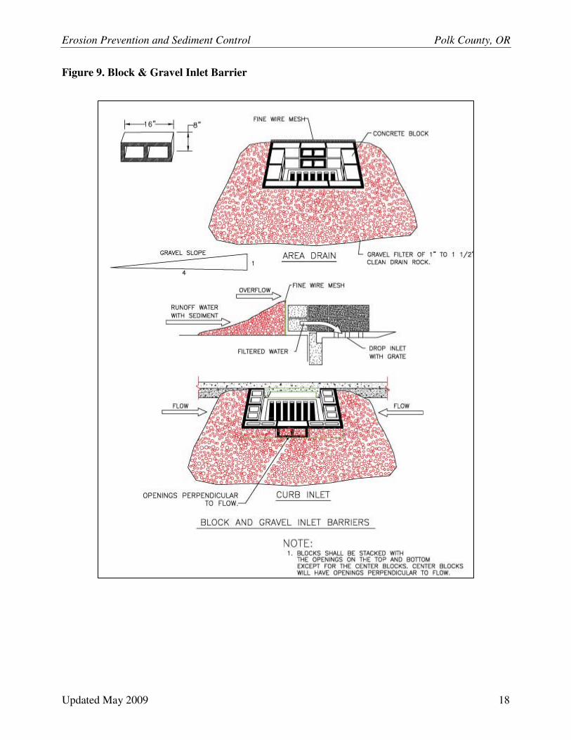
A. Design criteria and specifications for four recommended alternative methods of storm drain inlet protection are presented on Figures 8 through 10.
B. Berms may be required to direct drainage to flow through the filters and prevent bypassing of the inlets.
C. At no time should more than one foot depth of sediment be allowed to accumulate against storm drain inlet protection measures. Sediment should be removed and inlet protection measures restored as needed to maintain their sediment trapping and filtering capability.
D. Place inlet protection in areas where water can pond and where ponding will not have adverse impacts. Allow for an approved overflow in a severe storm event.
Erosion Prevention and Sediment Control Polk County, OR
Updated May 2009 17
Figure 8. Filter Fabric Inlet Barrier
Erosion Prevention and Sediment Control Polk County, OR
Updated May 2009 18
Figure 9. Block & Gravel Inlet Barrier
Erosion Prevention and Sediment Control Polk County, OR
Updated May 2009 19
Figure 10. Biofilter Bags Temporary
Erosion Prevention and Sediment Control Polk County, OR
Updated May 2009 20
3.0 Post-Construction Best Management Practices
Roof tops, parking lots, and driveways create impervious surfaces that concentrate stormwater run-off. Stormwater flowing over these developments pick up oil and other particle matter that can be harmful to riparian ecosystems. In order to decrease the quantity and increase the quality of stormwater that enters the County rivers and streams, construction operators should plan how to minimize stormwater runoff from new development prior to beginning construction. An online guidance handbook is available on the Polk County Stormwater Web Page (http://www.co.polk.or.us/Stormwater) that describes best management practices that can be used to minimize the impact of development on County rivers and streams. These best management practices include:
◊ Maintain native vegetation along rivers, streams, and sloped areas of your property
◊ Vegetated/Grassed Swales
◊ Bioretention (Rain Gardens)
◊ Pervious Pavement
◊ Downspout Disconnection
◊ Rain Barrel Construction
Resources and Contacts
Polk County Community Development Department……………………………….(503) 623-9237