Cisco Guide to Harden Cisco IOS Devices Document ID: 13608 Contributed by Shashank Singh, Cisco TAC Engineer. Jun 03, 2014 Contents Introduction Prerequisites Requirements Components Used Secure Operations Monitor Cisco Security Advisories and Responses Leverage Authentication, Authorization, and Accounting Centralize Log Collection and Monitoring Use Secure Protocols When Possible Gain Traffic Visibility with NetFlow Configuration Management Management Plane General Management Plane Hardening Password Management Enhanced Password Security Login Password Retry Lockout No Service Password-Recovery Disable Unused Services EXEC Timeout Keepalives for TCP Sessions Management Interface Use Memory Threshold Notifications CPU Thresholding Notification Reserve Memory for Console Access Memory Leak Detector Buffer Overflow: Detection and Correction of Redzone Corruption Enhanced Crashinfo File Collection Network Time Protocol Limit Access to the Network with Infrastructure ACLs ICMP Packet Filtering Filter IP Fragments ACL Support for Filtering IP Options ACL Support to Filter on TTL Value Secure Interactive Management Sessions Management Plane Protection Control Plane Protection Encrypt Management Sessions SSHv2 SSHv2 Enhancements for RSA Keys Console and AUX Ports Control vty and tty Lines Control Transport for vty and tty Lines Warning Banners Authentication, Authorization, and Accounting
Transcript
Cisco Guide to Harden Cisco IOS Devices
Document ID: 13608
Contributed by Shashank Singh, Cisco TAC Engineer.Jun 03, 2014
Contents
IntroductionPrerequisites Requirements Components UsedSecure Operations Monitor Cisco Security Advisories and Responses Leverage Authentication, Authorization, and Accounting Centralize Log Collection and Monitoring Use Secure Protocols When Possible Gain Traffic Visibility with NetFlow Configuration ManagementManagement Plane General Management Plane Hardening Password Management Enhanced Password Security Login Password Retry Lockout No Service Password−Recovery Disable Unused Services EXEC Timeout Keepalives for TCP Sessions Management Interface Use Memory Threshold Notifications CPU Thresholding Notification Reserve Memory for Console Access Memory Leak Detector Buffer Overflow: Detection and Correction of Redzone Corruption Enhanced Crashinfo File Collection Network Time Protocol Limit Access to the Network with Infrastructure ACLs ICMP Packet Filtering Filter IP Fragments ACL Support for Filtering IP Options ACL Support to Filter on TTL Value Secure Interactive Management Sessions Management Plane Protection Control Plane Protection Encrypt Management Sessions SSHv2 SSHv2 Enhancements for RSA Keys Console and AUX Ports Control vty and tty Lines Control Transport for vty and tty Lines Warning Banners Authentication, Authorization, and Accounting
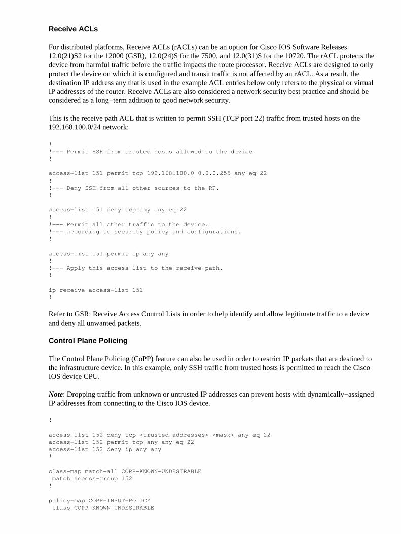
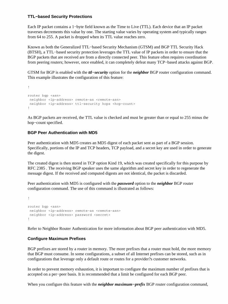
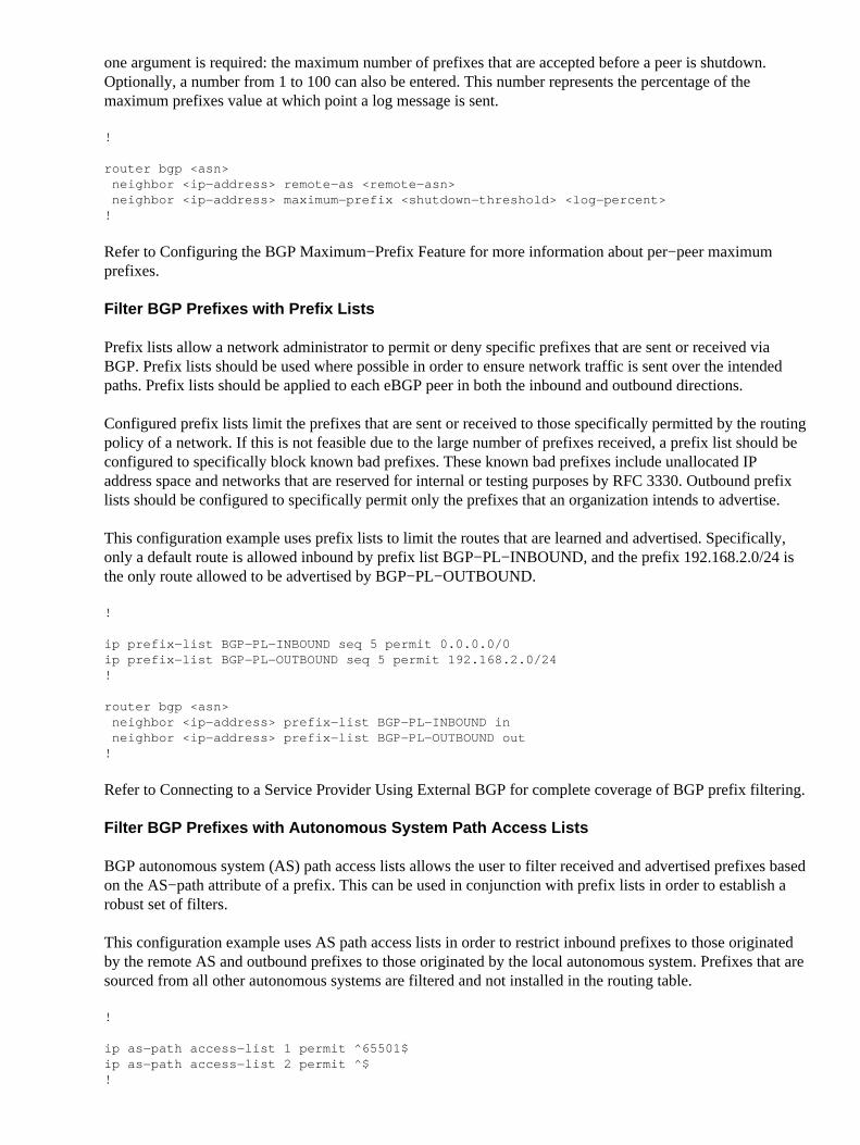
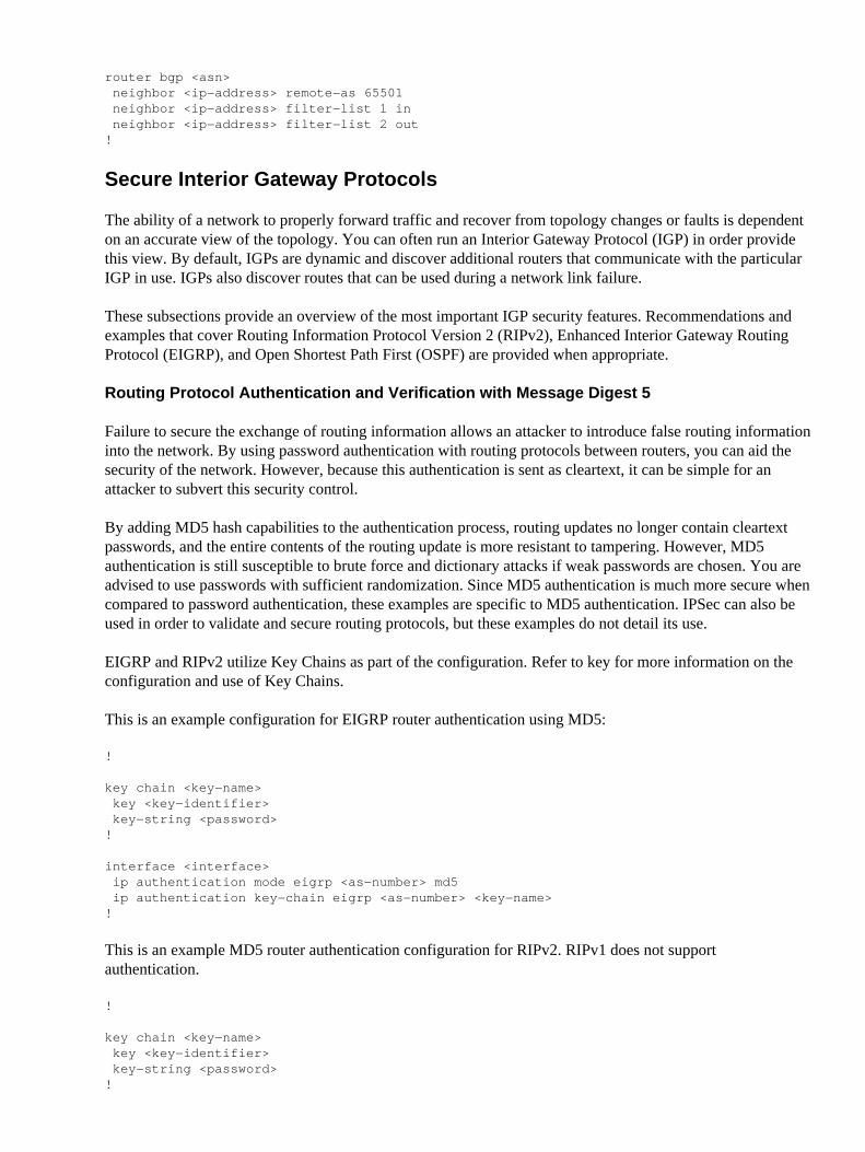
TACACS+ Authentication Authentication Fallback Use of Type 7 Passwords TACACS+ Command Authorization TACACS+ Command Accounting Redundant AAA Servers Fortify the Simple Network Management Protocol SNMP Community Strings SNMP Community Strings with ACLs Infrastructure ACLs SNMP Views SNMP Version 3 Management Plane Protection Logging Best Practices Send Logs to a Central Location Logging Level Do Not Log to Console or Monitor Sessions Use Buffered Logging Configure Logging Source Interface Configure Logging Timestamps Cisco IOS Software Configuration Management Configuration Replace and Configuration Rollback Exclusive Configuration Change Access Cisco IOS Software Resilient Configuration Digitally Signed Cisco Software Configuration Change Notification and LoggingControl Plane General Control Plane Hardening IP ICMP Redirects ICMP Unreachables Proxy ARP Limit CPU Impact of Control Plane Traffic Understand Control Plane Traffic Infrastructure ACLs Receive ACLs Control Plane Policing Control Plane Protection Hardware Rate Limiters Secure BGP TTL−based Security Protections BGP Peer Authentication with MD5 Configure Maximum Prefixes Filter BGP Prefixes with Prefix Lists Filter BGP Prefixes with Autonomous System Path Access Lists Secure Interior Gateway Protocols Routing Protocol Authentication and Verification with Message Digest 5 Passive−Interface Commands Route Filtering Routing Process Resource Consumption Secure First Hop Redundancy ProtocolsData Plane General Data Plane Hardening IP Options Selective Drop Disable IP Source Routing
Disable ICMP Redirects Disable or Limit IP Directed Broadcasts Filter Transit Traffic with Transit ACLs ICMP Packet Filtering Filter IP Fragments ACL Support for Filtering IP Options Anti−Spoofing Protections Unicast RPF IP Source Guard Port Security Dynamic ARP Inspection Anti−Spoofing ACLs Limit CPU Impact of Data Plane Traffic Features and Traffic Types that Impact the CPU Filter on TTL Value Filter on the Presence of IP Options Control Plane Protection Traffic Identification and Traceback NetFlow Classification ACLs Access Control with VLAN Maps and Port Access Control Lists Access Control with VLAN Maps Access Control with PACLs Access Control with MAC Private VLAN Use Isolated VLANs Community VLANs Promiscuous PortsConclusionAcknowledgmentsAppendix: Cisco IOS Device Hardening Checklist Management Plane Control Plane Data Plane
Introduction
This document contains information to help you secure your Cisco IOS® system devices, which increases theoverall security of your network. Structured around the three planes into which functions of a network devicecan be categorized, this document provides an overview of each included feature and references to relateddocumentation.
The three functional planes of a network − the management plane, control plane, and data plane − eachprovide different functionality that needs to be protected.
Management Plane − The management plane manages traffic that is sent to the Cisco IOS device andis made up of applications and protocols such as Secure Shell (SSH) and Simple NetworkManagement Protocol (SNMP).
•
Control Plane − The control plane of a network device processes the traffic that is paramount tomaintain the functionality of the network infrastructure. The control plane consists of applications andprotocols between network devices, which includes the Border Gateway Protocol (BGP), as well asthe Interior Gateway Protocols (IGPs) such as the Enhanced Interior Gateway Routing Protocol(EIGRP) and Open Shortest Path First (OSPF).
•
Data Plane − The data plane forwards data through a network device. The data plane does not includetraffic that is sent to the local Cisco IOS device.
•
The coverage of security features in this document often provides enough detail for you to configure thefeature. However, in cases where it does not, the feature is explained in such a way that you can evaluatewhether additional attention to the feature is required. Where possible and appropriate, this document containsrecommendations that, if implemented, help secure a network.
Prerequisites
Requirements
There are no specific requirements for this document.
Components Used
This document is not restricted to specific software and hardware versions.
The information in this document was created from the devices in a specific lab environment. All of thedevices used in this document started with a cleared (default) configuration. If your network is live, make surethat you understand the potential impact of any command.
Secure Operations
Secure network operations is a substantial topic. Although most of this document is devoted to the secureconfiguration of a Cisco IOS device, configurations alone do not completely secure a network. Theoperational procedures in use on the network contribute as much to security as the configuration of theunderlying devices.
These topics contain operational recommendations that you are advised to implement. These topics highlightspecific critical areas of network operations and are not comprehensive.
Monitor Cisco Security Advisories and Responses
The Cisco Product Security Incident Response Team (PSIRT) creates and maintains publications, commonlyreferred to as PSIRT Advisories, for security−related issues in Cisco products. The method used forcommunication of less severe issues is the Cisco Security Response. Security advisories and responses areavailable at http://www.cisco.com/go/psirt.
Additional information about these communication vehicles is available in the Cisco Security VulnerabilityPolicy.
In order to maintain a secure network, you need to be aware of the Cisco security advisories and responsesthat have been released. You need to have knowledge of a vulnerability before the threat it can pose to anetwork can be evaluated. Refer to Risk Triage for Security Vulnerability Announcements for assistance thisevaluation process.
Leverage Authentication, Authorization, and Accounting
The Authentication, Authorization, and Accounting (AAA) framework is vital to secure network devices. TheAAA framework provides authentication of management sessions and can also limit users to specific,administrator−defined commands and log all commands entered by all users. See the Authentication,
Authorization, and Accounting section of this document for more information about how to leverage AAA.
Centralize Log Collection and Monitoring
In order to gain knowledge about existing, emerging, and historic events related to security incidents, yourorganization must have a unified strategy for event logging and correlation. This strategy must leveragelogging from all network devices and use pre−packaged and customizable correlation capabilities.
After centralized logging is implemented, you must develop a structured approach to log analysis and incidenttracking. Based on the needs of your organization, this approach can range from a simple diligent review oflog data to advanced rule−based analysis.
See the Logging Best Practices section of this document for more information about how to implementlogging on Cisco IOS network devices.
Use Secure Protocols When Possible
Many protocols are used in order to carry sensitive network management data. You must use secure protocolswhenever possible. A secure protocol choice includes the use of SSH instead of Telnet so that bothauthentication data and management information are encrypted. In addition, you must use secure file transferprotocols when you copy configuration data. An example is the use of the Secure Copy Protocol (SCP) inplace of FTP or TFTP.
See the Secure Interactive Management Sessions section of this document for more information about thesecure management of Cisco IOS devices.
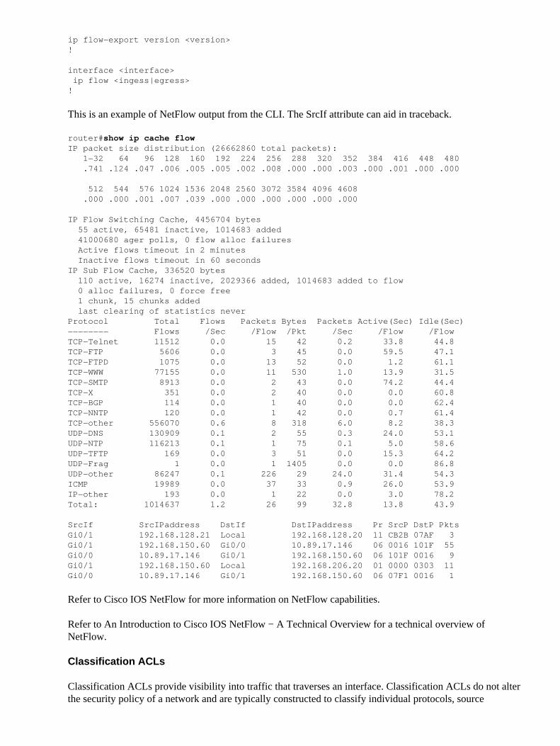
Gain Traffic Visibility with NetFlow
NetFlow enables you to monitor traffic flows in the network. Originally intended to export traffic informationto network management applications, NetFlow can also be used in order to show flow information on a router.This capability allows you to see what traffic traverses the network in real time. Regardless of whether flowinformation is exported to a remote collector, you are advised to configure network devices for NetFlow sothat it can be used reactively if needed.
More information about this feature is available in the Traffic Identification and Traceback section of thisdocument and at http://www.cisco.com/go/netflow (registered customers only) .
Configuration Management
Configuration management is a process by which configuration changes are proposed, reviewed, approved,and deployed. Within the context of a Cisco IOS device configuration, two additional aspects of configurationmanagement are critical: configuration archival and security.
You can use configuration archives to roll back changes that are made to network devices. In a securitycontext, configuration archives can also be used in order to determine which security changes were made andwhen these changes occurred. In conjunction with AAA log data, this information can assist in the securityauditing of network devices.
The configuration of a Cisco IOS device contains many sensitive details. Usernames, passwords, and thecontents of access control lists are examples of this type of information. The repository that you use in orderto archive Cisco IOS device configurations needs to be secured. Insecure access to this information canundermine the security of the entire network.
Management Plane
The management plane consists of functions that achieve the management goals of the network. This includesinteractive management sessions that use SSH, as well as statistics−gathering with SNMP or NetFlow. Whenyou consider the security of a network device, it is critical that the management plane be protected. If asecurity incident is able to undermine the functions of the management plane, it can be impossible for you torecover or stabilize the network.
These sections of this document detail the security features and configurations available in Cisco IOSsoftware that help fortify the management plane.
General Management Plane Hardening
The management plane is used in order to access, configure, and manage a device, as well as monitor itsoperations and the network on which it is deployed. The management plane is the plane that receives andsends traffic for operations of these functions. You must secure both the management plane and control planeof a device, because operations of the control plane directly affect operations of the management plane. Thislist of protocols is used by the management plane:
Simple Network Management Protocol• Telnet• Secure Shell Protocol• File Transfer Protocol• Trivial File Transfer Protocol• Secure Copy Protocol• TACACS+• RADIUS• NetFlow• Network Time Protocol• Syslog•
Steps must be taken to ensure the survival of the management and control planes during security incidents. Ifone of these planes is successfully exploited, all planes can be compromised.
Password Management
Passwords control access to resources or devices. This is accomplished through the definition a password orsecret that is used in order to authenticate requests. When a request is received for access to a resource ordevice, the request is challenged for verification of the password and identity, and access can be granted,denied, or limited based on the result. As a security best practice, passwords must be managed with aTACACS+ or RADIUS authentication server. However, note that a locally configured password forprivileged access is still needed in the event of failure of the TACACS+ or RADIUS services. A device canalso have other password information present within its configuration, such as an NTP key, SNMPcommunity string, or Routing Protocol key.
The enable secret command is used in order to set the password that grants privileged administrative access tothe Cisco IOS system. The enable secret command must be used, rather than the older enable passwordcommand. The enable password command uses a weak encryption algorithm.
If no enable secret is set and a password is configured for the console tty line, the console password can beused in order to receive privileged access, even from a remote virtual tty (vty) session. This action is almostcertainly unwanted and is another reason to ensure configuration of an enable secret.
The service password−encryption global configuration command directs the Cisco IOS software to encryptthe passwords, Challenge Handshake Authentication Protocol (CHAP) secrets, and similar data that are savedin its configuration file. Such encryption is useful in order to prevent casual observers from readingpasswords, such as when they look at the screen over the muster of an administrator. However, the algorithmused by the service password−encryption command is a simple Vigen re cipher. The algorithm is notdesigned to protect configuration files against serious analysis by even slightly sophisticated attackers andmust not be used for this purpose. Any Cisco IOS configuration file that contains encrypted passwords mustbe treated with the same care that is used for a cleartext list of those same passwords.
While this weak encryption algorithm is not used by the enable secret command, it is used by the enablepassword global configuration command, as well as the password line configuration command. Passwords ofthis type must be eliminated and the enable secret command or the Enhanced Password Security feature needsto be used.
The enable secret command and the Enhanced Password Security feature use Message Digest 5 (MD5) forpassword hashing. This algorithm has had considerable public review and is not known to be reversible.However, the algorithm is subject to dictionary attacks. In a dictionary attack, an attacker tries every word in adictionary or other list of candidate passwords in order to find a match. Therefore, configuration files must besecurely stored and only shared with trusted individuals.
Enhanced Password Security
The feature Enhanced Password Security, introduced in Cisco IOS Software Release 12.2(8)T, allows anadministrator to configure MD5 hashing of passwords for the username command. Prior to this feature, therewere two types of passwords: Type 0, which is a cleartext password, and Type 7, which uses the algorithmfrom the Vigen re cipher. The Enhanced Password Security feature cannot be used with protocols that requirethe cleartext password to be retrievable, such as CHAP.
In order to encrypt a user password with MD5 hashing, issue the username secret global configurationcommand.
!
username <name> secret <password>
!
Refer to Enhanced Password Security for more information about this feature.
Login Password Retry Lockout
The Login Password Retry Lockout feature, added in Cisco IOS Software Release 12.3(14)T, allows you tolock out a local user account after a configured number of unsuccessful login attempts. Once a user is lockedout, their account is locked until you unlock it. An authorized user who is configured with privilege level 15cannot be locked out with this feature. The number of users with privilege level 15 must be kept to aminimum.
Note that authorized users can lock themselves out of a device if the number of unsuccessful login attempts isreached. Additionally, a malicious user can create a denial of service (DoS) condition with repeated attemptsto authenticate with a valid username.
This example shows how to enable the Login Password Retry Lockout feature:
!
aaa new−model
aaa local authentication attempts max−fail <max−attempts>aaa authentication login default local
!
username <name> secret <password>
!
This feature also applies to authentication methods such as CHAP and Password Authentication Protocol(PAP).
No Service Password−Recovery
In Cisco IOS Software Release 12.3(14)T and later, the No Service Password−Recovery feature does notallow anyone with console access to insecurely access the device configuration and clear the password. It alsodoes not allow malicious users to change the configuration register value and access NVRAM.
!
no service password−recovery
!
Cisco IOS software provides a password recovery procedure that relies upon access to ROM Monitor Mode(ROMMON) using the Break key during system startup. In ROMMON, the device software can be reloadedin order to prompt a new system configuration that includes a new password.
The current password recovery procedure enables anyone with console access to access the device and itsnetwork. The No Service Password−Recovery feature prevents the completion of the Break key sequence andthe entering of ROMMON during system startup.
If no service password−recovery is enabled on a device, it is recommended that an offline copy of the deviceconfiguration be saved and that a configuration archiving solution be implemented. If it is necessary torecover the password of a Cisco IOS device once this feature is enabled, the entire configuration is deleted.
Refer to Secure ROMMON Configuration Example for more information about this feature.
Disable Unused Services
As a security best practice, any unnecessary service must be disabled. These unneeded services, especiallythose that use User Datagram Protocol (UDP), are infrequently used for legitimate purposes, but can be usedin order to launch DoS and other attacks that are otherwise prevented by packet filtering.
The TCP and UDP small services must be disabled. These services include:
echo (port number 7)• discard (port number 9)• daytime (port number 13)• chargen (port number 19)•
Although abuse of the small services can be avoided or made less dangerous by anti−spoofing access lists, theservices must be disabled on any device accessible within the network. The small services are disabled bydefault in Cisco IOS Software Releases 12.0 and later. In earlier software, the no service tcp−small−serversand no service udp−small−servers global configuration commands can be issued in order to disable them.
This is a list of additional services that must be disabled if not in use:
Issue the no ip finger global configuration command in order to disable Finger service. Cisco IOSsoftware releases later than 12.1(5) and 12.1(5)T disable this service by default.
•
Issue the no ip bootp server global configuration command in order to disable Bootstrap Protocol(BOOTP).
•
In Cisco IOS Software Release 12.2(8)T and later, issue the ip dhcp bootp ignore command in globalconfiguration mode in order to disable BOOTP. This leaves Dynamic Host Configuration Protocol(DHCP) services enabled.
•
DHCP services can be disabled if DHCP relay services are not required. Issue the no service dhcpcommand in global configuration mode.
•
Issue the no mop enabled command in interface configuration mode in order to disable theMaintenance Operation Protocol (MOP) service.
•
Issue the no ip domain−lookup global configuration command in order to disable Domain NameSystem (DNS) resolution services.
•
Issue the no service pad command in global configuration mode in order to disable PacketAssembler/Disassembler (PAD) service, which is used for X.25 networks.
•
The HTTP server can be disabled with the no ip http server command in global configuration mode,and Secure HTTP (HTTPS) server can be disabled with the no ip http secure−server globalconfiguration command.
•
Unless Cisco IOS devices retrieve configurations from the network during startup, the no serviceconfig global configuration command must be used. This prevents the Cisco IOS device from anattempt to locate a configuration file on the network with TFTP.
•
Cisco Discovery Protocol (CDP) is a network protocol that is used in order to discover other CDPenabled devices for neighbor adjacency and network topology. CDP can be used by NetworkManagement Systems (NMS) or during troubleshooting. CDP must be disabled on all interfaces thatare connected to untrusted networks. This is accomplished with the no cdp enable interfacecommand. Alternatively, CDP can be disabled globally with the no cdp run global configurationcommand. Note that CDP can be used by a malicious user for reconnaissance and network mapping.
•
Link Layer Discovery Protocol (LLDP) is an IEEE protocol that is defined in 802.1AB. LLDP issimilar to CDP. However, this protocol allows interoperability between other devices that do notsupport CDP. LLDP must be treated in the same manner as CDP and disabled on all interfaces thatconnect to untrusted networks. In order to accomplish this, issue the no lldp transmit and no lldpreceive interface configuration commands. Issue the no lldp run global configuration command inorder to disable LLDP globally. LLDP can also be used by a malicious user for reconnaissance andnetwork mapping.
•
EXEC Timeout
In order to set the interval that the EXEC command interpreter waits for user input before it terminates asession, issue the exec−timeout line configuration command. The exec−timeout command must be used inorder to logout sessions on vty or tty lines that are left idle. By default, sessions are disconnected after 10minutes of inactivity.
!
line con 0 exec−timeout <minutes> [seconds]line vty 0 4 exec−timeout <minutes> [seconds]!
Keepalives for TCP Sessions
The service tcp−keepalives−in and service tcp−keepalives−out global configuration commands enable adevice to send TCP keepalives for TCP sessions. This configuration must be used in order to enable TCPkeepalives on inbound connections to the device and outbound connections from the device. This ensures thatthe device on the remote end of the connection is still accessible and that half−open or orphaned connectionsare removed from the local Cisco IOS device.
!
service tcp−keepalives−inservice tcp−keepalives−out!
Management Interface Use
The management plane of a device is accessed in−band or out−of−band on a physical or logical managementinterface. Ideally, both in−band and out−of−band management access exists for each network device so thatthe management plane can be accessed during network outages.
One of the most common interfaces that is used for in−band access to a device is the logical loopbackinterface. Loopback interfaces are always up, whereas physical interfaces can change state, and the interfacecan potentially not be accessible. It is recommended to add a loopback interface to each device as amanagement interface and that it be used exclusively for the management plane. This allows the administratorto apply policies throughout the network for the management plane. Once the loopback interface is configuredon a device, it can be used by management plane protocols, such as SSH, SNMP, and syslog, in order to sendand receive traffic.
!interface Loopback0 ip address 192.168.1.1 255.255.255.0!
Memory Threshold Notifications
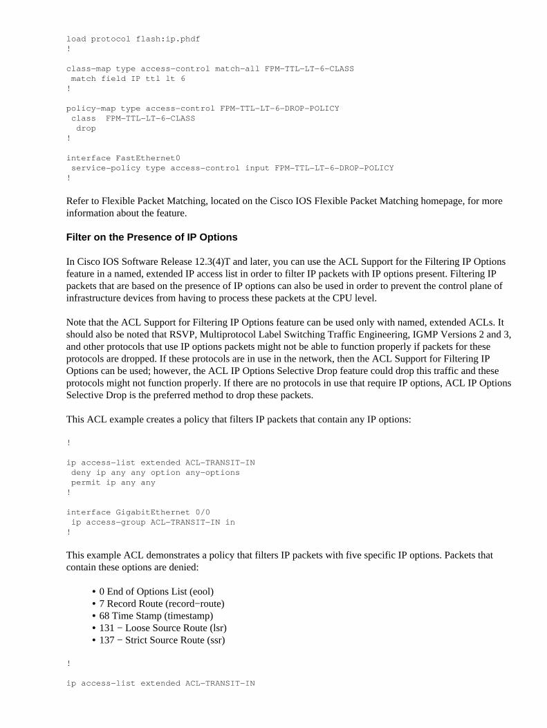
The feature Memory Threshold Notification, added in Cisco IOS Software Release 12.3(4)T, allows you tomitigate low−memory conditions on a device. This feature uses two methods in order to accomplish this:Memory Threshold Notification and Memory Reservation.
Memory Threshold Notification generates a log message in order to indicate that free memory on a device hasfallen lower than the configured threshold. This configuration example shows how to enable this feature withthe memory free low−watermark global configuration command. This enables a device to generate anotification when available free memory falls lower than the specified threshold, and again when availablefree memory rises to five percent higher than the specified threshold.
Memory Reservation is used so that sufficient memory is available for critical notifications. Thisconfiguration example demonstrates how to enable this feature. This ensures that management processescontinue to function when the memory of the device is exhausted.
!memory reserve critical <value>!
Refer to Memory Threshold Notifications for more information about this feature.
CPU Thresholding Notification
Introduced in Cisco IOS Software Release 12.3(4)T, the CPU Thresholding Notification feature allows you todetect and be notified when the CPU load on a device crosses a configured threshold. When the threshold iscrossed, the device generates and sends an SNMP trap message. Two CPU utilization thresholding methodsare supported on Cisco IOS software: Rising Threshold and Falling Threshold.
This example configuration shows how to enable the Rising and Falling Thresholds that trigger a CPUthreshold notification message:
!
snmp−server enable traps cpu threshold!
snmp−server host <host−address> <community−string> cpu !
process cpu threshold type <type> rising <percentage> interval <seconds> [falling <percentage> interval <seconds>]process cpu statistics limit entry−percentage <number> [size <seconds>]!
Refer to CPU Thresholding Notification for more information about this feature.
Reserve Memory for Console Access
In Cisco IOS Software Release 12.4(15)T and later, the Reserve Memory for Console Access feature can beused in order to reserve enough memory to ensure console access to a Cisco IOS device for administrative andtroubleshooting purposes. This feature is especially beneficial when the device runs low on memory. You canissue the memory reserve console global configuration command in order to enable this feature. This exampleconfigures a Cisco IOS device to reserve 4096 kilobytes for this purpose.
!memory reserve console 4096!
Refer to Reserve Memory for Console Access for more information about this feature.
Memory Leak Detector
Introduced in Cisco IOS Software Release 12.3(8)T1, the Memory Leak Detector feature allows you to detectmemory leaks on a device. Memory Leak Detector is able to find leaks in all memory pools, packet buffers,and chunks. Memory leaks are static or dynamic allocations of memory that do not serve any useful purpose.This feature focuses on memory allocations that are dynamic. You can use the show memory debug leaksEXEC command in order to detect if a memory leak exists.
Buffer Overflow: Detection and Correction of Redzone Corruption
In Cisco IOS Software Release 12.3(7)T and later, the Buffer Overflow: Detection and Correction of RedzoneCorruption feature can be enabled by on a device in order to detect and correct a memory block overflow andto continue operations.
These global configuration commands can be used in order to enable this feature. Once configured, the showmemory overflow command can be used in order to display the buffer overflow detection and correction
The Enhanced Crashinfo File Collection feature automatically deletes old crashinfo files. This feature, addedin Cisco IOS Software Release 12.3(11)T, allows a device to reclaim space in order to create new crashinfofiles when the device crashes. This feature also allows configuration of the number of crashinfo files to besaved.
!exception crashinfo maximum files <number−of−files>!
Network Time Protocol
The Network Time Protocol (NTP) is not an especially dangerous service, but any unneeded service canrepresent an attack vector. If NTP is used, it is important to explicitly configure a trusted time source and touse proper authentication. Accurate and reliable time is required for syslog purposes, such as during forensicinvestigations of potential attacks, as well as for successful VPN connectivity when depending on certificatesfor Phase 1 authentication.
NTP Time Zone − When you configure NTP, the time zone needs to be configured so thattimestamps can be accurately correlated. There are usually two approaches to configure the time zonefor devices in a network with a global presence. One method is to configure all network devices withthe Coordinated Universal Time (UTC) (previously Greenwich Mean Time (GMT)). The otherapproach is to configure network devices with the local time zone. More information on this featurecan be found in ?clock timezone? in the Cisco product documentation.
•
NTP Authentication − If you configure NTP authentication, it provides assurance that NTP messagesare exchanged between trusted NTP peers.
•
Limit Access to the Network with Infrastructure ACLs
Devised to prevent unauthorized direct communication to network devices, infrastructure access control lists(iACLs) are one of the most critical security controls that can be implemented in networks. InfrastructureACLs leverage the idea that nearly all network traffic traverses the network and is not destined to the networkitself.
An iACL is constructed and applied in order to specify connections from hosts or networks that need to beallowed to network devices. Common examples of these types of connections are eBGP, SSH, and SNMP.After the required connections have been permitted, all other traffic to the infrastructure is explicitly denied.All transit traffic that crosses the network and is not destined to infrastructure devices is then explicitlypermitted.
The protections provided by iACLs are relevant to both the management and control planes. Theimplementation of iACLs can be made easier through the use of distinct addressing for network infrastructuredevices. Refer to A Security Oriented Approach to IP Addressing for more information on the securityimplications of IP addressing.
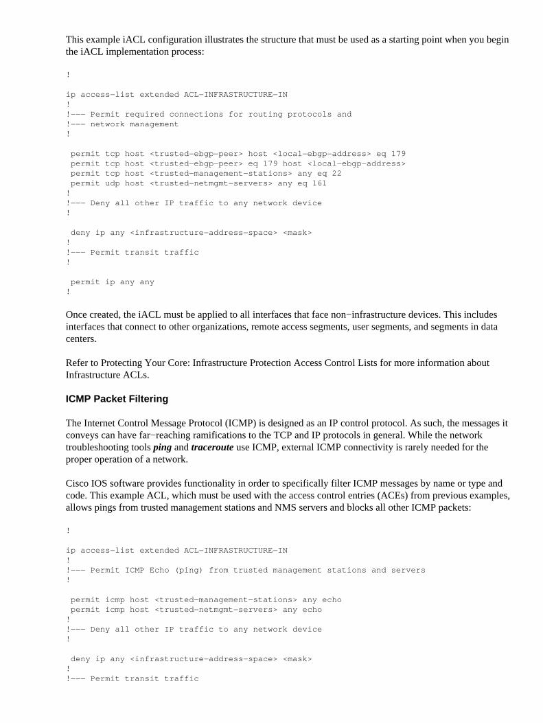
This example iACL configuration illustrates the structure that must be used as a starting point when you beginthe iACL implementation process:
!
ip access−list extended ACL−INFRASTRUCTURE−IN!!−−− Permit required connections for routing protocols and!−−− network management!
permit tcp host <trusted−ebgp−peer> host <local−ebgp−address> eq 179 permit tcp host <trusted−ebgp−peer> eq 179 host <local−ebgp−address> permit tcp host <trusted−management−stations> any eq 22 permit udp host <trusted−netmgmt−servers> any eq 161!!−−− Deny all other IP traffic to any network device!
deny ip any <infrastructure−address−space> <mask>!!−−− Permit transit traffic!
permit ip any any!
Once created, the iACL must be applied to all interfaces that face non−infrastructure devices. This includesinterfaces that connect to other organizations, remote access segments, user segments, and segments in datacenters.
Refer to Protecting Your Core: Infrastructure Protection Access Control Lists for more information aboutInfrastructure ACLs.
ICMP Packet Filtering
The Internet Control Message Protocol (ICMP) is designed as an IP control protocol. As such, the messages itconveys can have far−reaching ramifications to the TCP and IP protocols in general. While the networktroubleshooting tools ping and traceroute use ICMP, external ICMP connectivity is rarely needed for theproper operation of a network.
Cisco IOS software provides functionality in order to specifically filter ICMP messages by name or type andcode. This example ACL, which must be used with the access control entries (ACEs) from previous examples,allows pings from trusted management stations and NMS servers and blocks all other ICMP packets:
!
ip access−list extended ACL−INFRASTRUCTURE−IN!!−−− Permit ICMP Echo (ping) from trusted management stations and servers!
permit icmp host <trusted−management−stations> any echo permit icmp host <trusted−netmgmt−servers> any echo!!−−− Deny all other IP traffic to any network device!
deny ip any <infrastructure−address−space> <mask>!!−−− Permit transit traffic
!
permit ip any any!
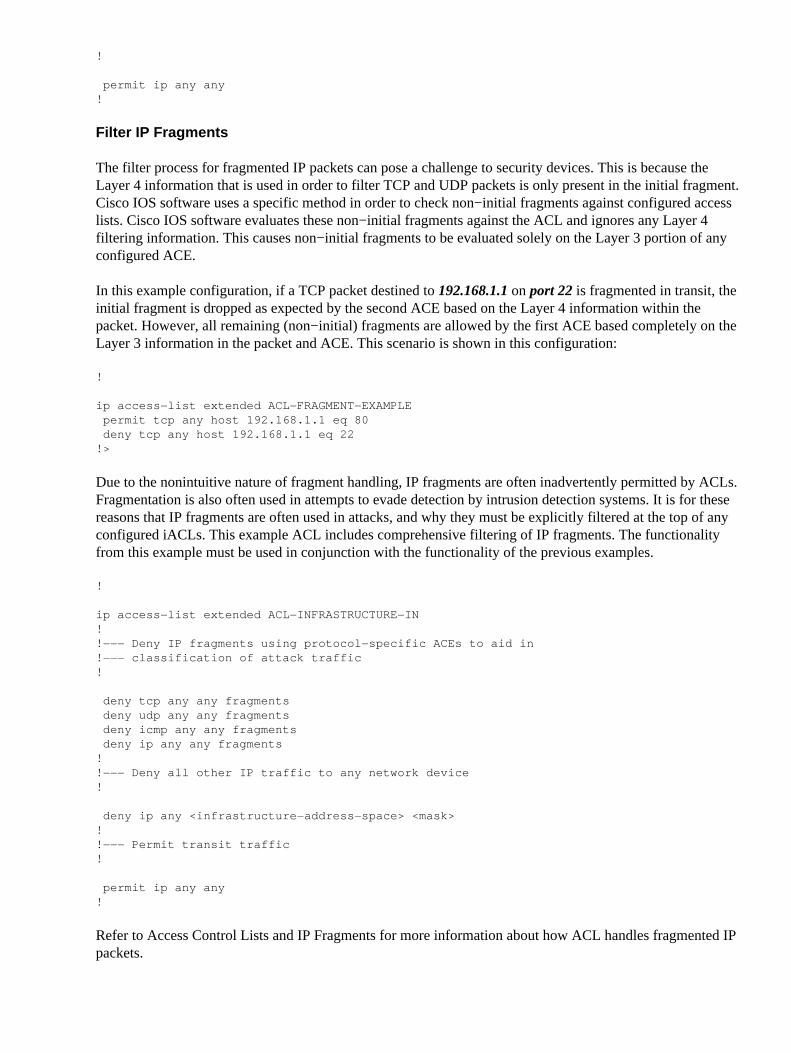
Filter IP Fragments
The filter process for fragmented IP packets can pose a challenge to security devices. This is because theLayer 4 information that is used in order to filter TCP and UDP packets is only present in the initial fragment.Cisco IOS software uses a specific method in order to check non−initial fragments against configured accesslists. Cisco IOS software evaluates these non−initial fragments against the ACL and ignores any Layer 4filtering information. This causes non−initial fragments to be evaluated solely on the Layer 3 portion of anyconfigured ACE.
In this example configuration, if a TCP packet destined to 192.168.1.1 on port 22 is fragmented in transit, theinitial fragment is dropped as expected by the second ACE based on the Layer 4 information within thepacket. However, all remaining (non−initial) fragments are allowed by the first ACE based completely on theLayer 3 information in the packet and ACE. This scenario is shown in this configuration:
!
ip access−list extended ACL−FRAGMENT−EXAMPLE permit tcp any host 192.168.1.1 eq 80 deny tcp any host 192.168.1.1 eq 22!>
Due to the nonintuitive nature of fragment handling, IP fragments are often inadvertently permitted by ACLs.Fragmentation is also often used in attempts to evade detection by intrusion detection systems. It is for thesereasons that IP fragments are often used in attacks, and why they must be explicitly filtered at the top of anyconfigured iACLs. This example ACL includes comprehensive filtering of IP fragments. The functionalityfrom this example must be used in conjunction with the functionality of the previous examples.
!
ip access−list extended ACL−INFRASTRUCTURE−IN!!−−− Deny IP fragments using protocol−specific ACEs to aid in!−−− classification of attack traffic!
deny tcp any any fragments deny udp any any fragments deny icmp any any fragments deny ip any any fragments!!−−− Deny all other IP traffic to any network device!
deny ip any <infrastructure−address−space> <mask>!!−−− Permit transit traffic!
permit ip any any!
Refer to Access Control Lists and IP Fragments for more information about how ACL handles fragmented IPpackets.
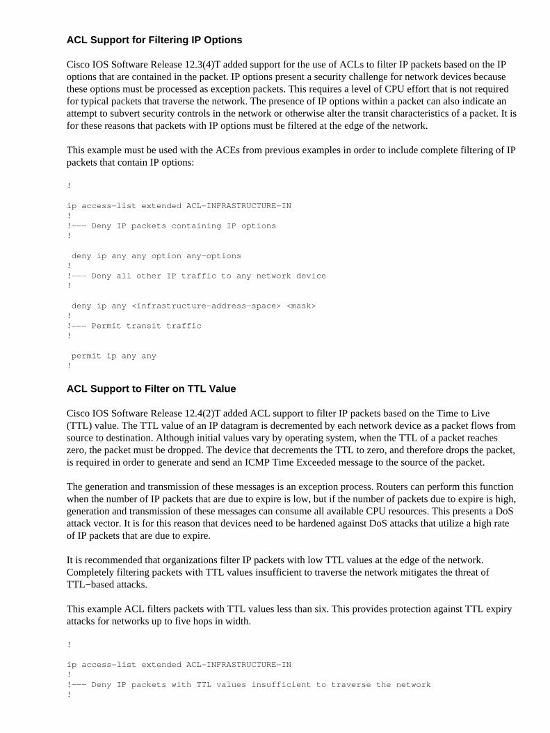
ACL Support for Filtering IP Options
Cisco IOS Software Release 12.3(4)T added support for the use of ACLs to filter IP packets based on the IPoptions that are contained in the packet. IP options present a security challenge for network devices becausethese options must be processed as exception packets. This requires a level of CPU effort that is not requiredfor typical packets that traverse the network. The presence of IP options within a packet can also indicate anattempt to subvert security controls in the network or otherwise alter the transit characteristics of a packet. It isfor these reasons that packets with IP options must be filtered at the edge of the network.
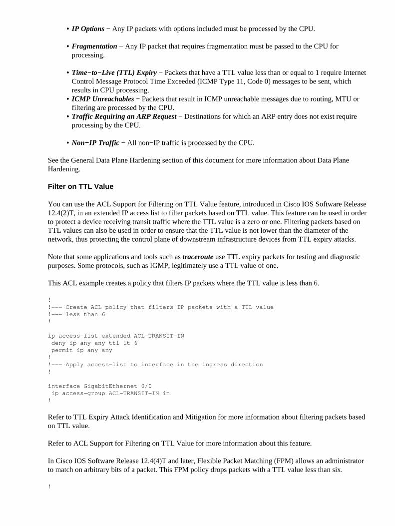
This example must be used with the ACEs from previous examples in order to include complete filtering of IPpackets that contain IP options:
!
ip access−list extended ACL−INFRASTRUCTURE−IN!!−−− Deny IP packets containing IP options!
deny ip any any option any−options!!−−− Deny all other IP traffic to any network device!
deny ip any <infrastructure−address−space> <mask>!!−−− Permit transit traffic!
permit ip any any!
ACL Support to Filter on TTL Value
Cisco IOS Software Release 12.4(2)T added ACL support to filter IP packets based on the Time to Live(TTL) value. The TTL value of an IP datagram is decremented by each network device as a packet flows fromsource to destination. Although initial values vary by operating system, when the TTL of a packet reacheszero, the packet must be dropped. The device that decrements the TTL to zero, and therefore drops the packet,is required in order to generate and send an ICMP Time Exceeded message to the source of the packet.
The generation and transmission of these messages is an exception process. Routers can perform this functionwhen the number of IP packets that are due to expire is low, but if the number of packets due to expire is high,generation and transmission of these messages can consume all available CPU resources. This presents a DoSattack vector. It is for this reason that devices need to be hardened against DoS attacks that utilize a high rateof IP packets that are due to expire.
It is recommended that organizations filter IP packets with low TTL values at the edge of the network.Completely filtering packets with TTL values insufficient to traverse the network mitigates the threat ofTTL−based attacks.
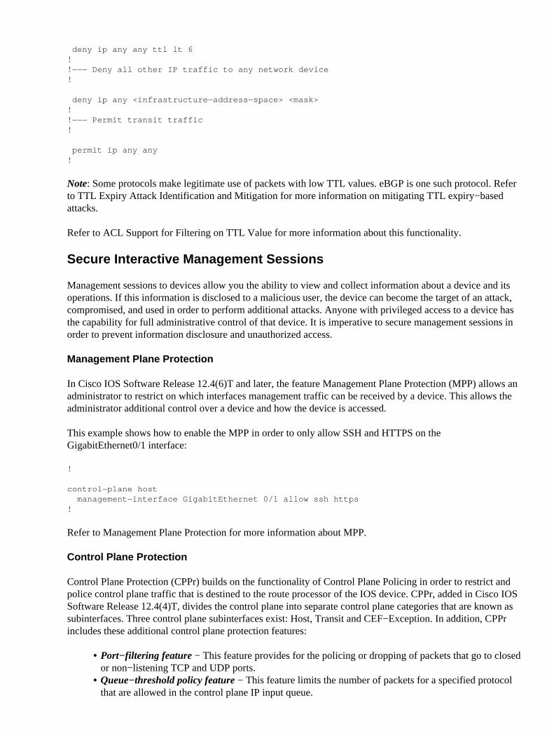
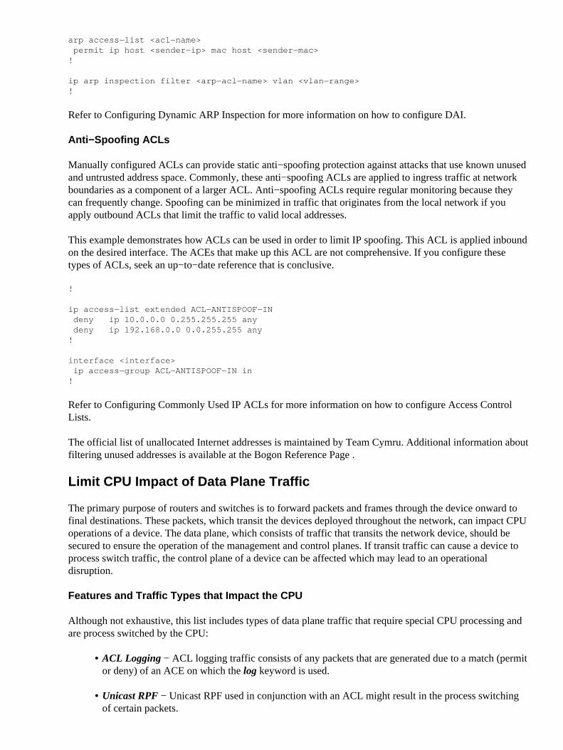
This example ACL filters packets with TTL values less than six. This provides protection against TTL expiryattacks for networks up to five hops in width.
!
ip access−list extended ACL−INFRASTRUCTURE−IN!!−−− Deny IP packets with TTL values insufficient to traverse the network!
deny ip any any ttl lt 6!!−−− Deny all other IP traffic to any network device!
deny ip any <infrastructure−address−space> <mask>!!−−− Permit transit traffic!
permit ip any any!
Note: Some protocols make legitimate use of packets with low TTL values. eBGP is one such protocol. Referto TTL Expiry Attack Identification and Mitigation for more information on mitigating TTL expiry−basedattacks.
Refer to ACL Support for Filtering on TTL Value for more information about this functionality.
Secure Interactive Management Sessions
Management sessions to devices allow you the ability to view and collect information about a device and itsoperations. If this information is disclosed to a malicious user, the device can become the target of an attack,compromised, and used in order to perform additional attacks. Anyone with privileged access to a device hasthe capability for full administrative control of that device. It is imperative to secure management sessions inorder to prevent information disclosure and unauthorized access.
Management Plane Protection
In Cisco IOS Software Release 12.4(6)T and later, the feature Management Plane Protection (MPP) allows anadministrator to restrict on which interfaces management traffic can be received by a device. This allows theadministrator additional control over a device and how the device is accessed.
This example shows how to enable the MPP in order to only allow SSH and HTTPS on theGigabitEthernet0/1 interface:
Refer to Management Plane Protection for more information about MPP.
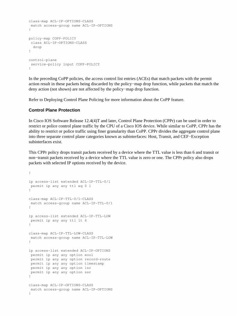
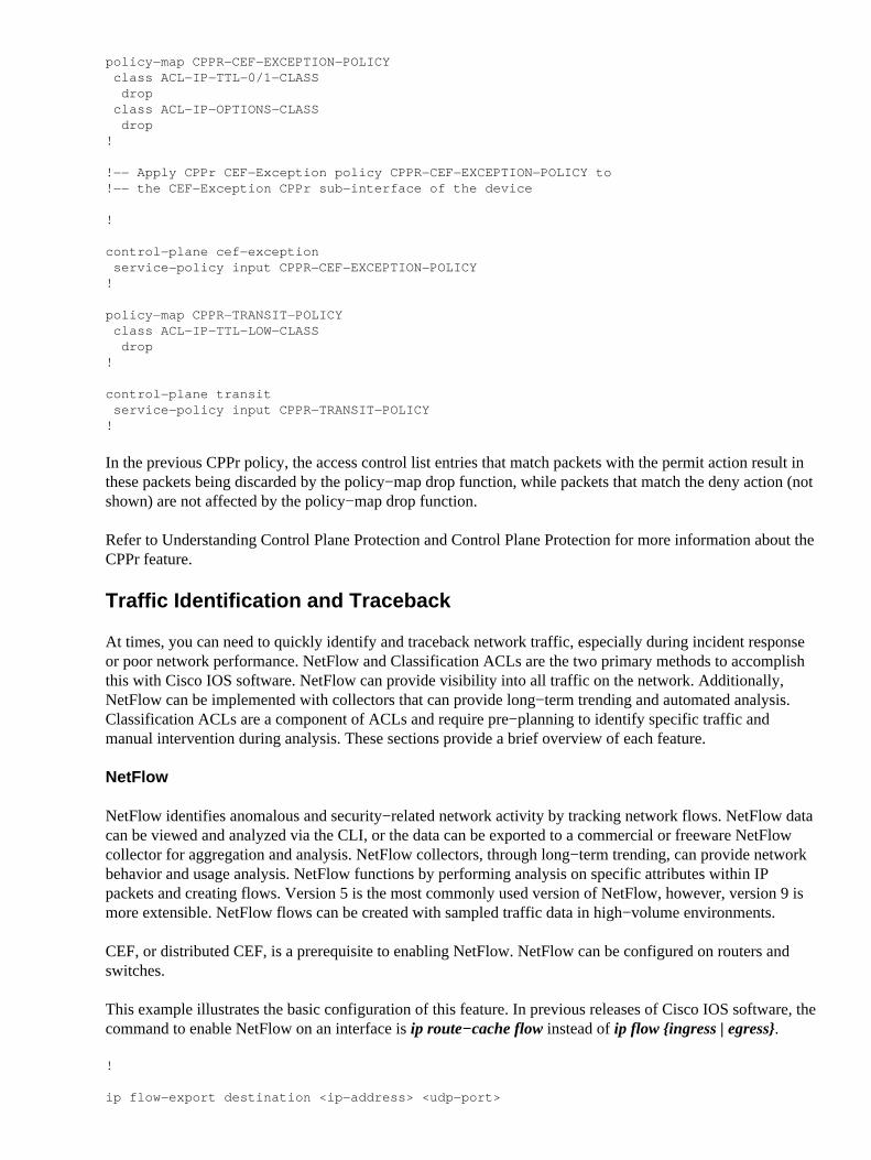
Control Plane Protection
Control Plane Protection (CPPr) builds on the functionality of Control Plane Policing in order to restrict andpolice control plane traffic that is destined to the route processor of the IOS device. CPPr, added in Cisco IOSSoftware Release 12.4(4)T, divides the control plane into separate control plane categories that are known assubinterfaces. Three control plane subinterfaces exist: Host, Transit and CEF−Exception. In addition, CPPrincludes these additional control plane protection features:
Port−filtering feature − This feature provides for the policing or dropping of packets that go to closedor non−listening TCP and UDP ports.
•
Queue−threshold policy feature − This feature limits the number of packets for a specified protocolthat are allowed in the control plane IP input queue.
•
CPPr allows an administrator to classify, police, and restrict traffic that is sent to a device for managementpurposes with the host subinterface. Examples of packets that are classified for the host subinterface categoryinclude management traffic such as SSH or Telnet and routing protocols.
Note: CPPr does not support IPv6 and is restricted to the IPv4 input path.
Refer to Control Plane Protection Feature Guide − 12.4T and Understanding Control Plane Protection formore information about the Cisco CPPr feature.
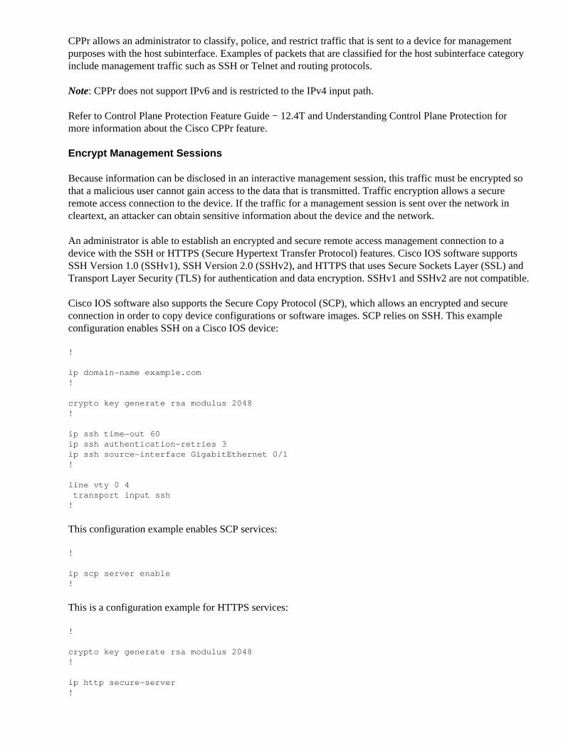
Encrypt Management Sessions
Because information can be disclosed in an interactive management session, this traffic must be encrypted sothat a malicious user cannot gain access to the data that is transmitted. Traffic encryption allows a secureremote access connection to the device. If the traffic for a management session is sent over the network incleartext, an attacker can obtain sensitive information about the device and the network.
An administrator is able to establish an encrypted and secure remote access management connection to adevice with the SSH or HTTPS (Secure Hypertext Transfer Protocol) features. Cisco IOS software supportsSSH Version 1.0 (SSHv1), SSH Version 2.0 (SSHv2), and HTTPS that uses Secure Sockets Layer (SSL) andTransport Layer Security (TLS) for authentication and data encryption. SSHv1 and SSHv2 are not compatible.
Cisco IOS software also supports the Secure Copy Protocol (SCP), which allows an encrypted and secureconnection in order to copy device configurations or software images. SCP relies on SSH. This exampleconfiguration enables SSH on a Cisco IOS device:
This is a configuration example for HTTPS services:
!
crypto key generate rsa modulus 2048!
ip http secure−server!
Refer to Configuring Secure Shell on Routers and Switches Running Cisco IOS and Secure Shell (SSH) FAQfor more information about the Cisco IOS software SSH feature.
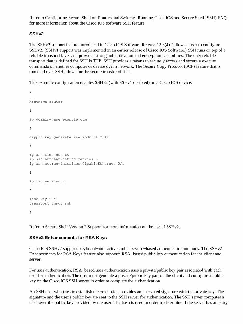
SSHv2
The SSHv2 support feature introduced in Cisco IOS Software Release 12.3(4)T allows a user to configureSSHv2. (SSHv1 support was implemented in an earlier release of Cisco IOS Software.) SSH runs on top of areliable transport layer and provides strong authentication and encryption capabilities. The only reliabletransport that is defined for SSH is TCP. SSH provides a means to securely access and securely executecommands on another computer or device over a network. The Secure Copy Protocol (SCP) feature that istunneled over SSH allows for the secure transfer of files.
This example configuration enables SSHv2 (with SSHv1 disabled) on a Cisco IOS device:
!
hostname router
!
ip domain−name example.com
!
crypto key generate rsa modulus 2048
!
ip ssh time−out 60 ip ssh authentication−retries 3 ip ssh source−interface GigabitEthernet 0/1
!
ip ssh version 2
!
line vty 0 4 transport input ssh
!
Refer to Secure Shell Version 2 Support for more information on the use of SSHv2.
SSHv2 Enhancements for RSA Keys
Cisco IOS SSHv2 supports keyboard−interactive and password−based authentication methods. The SSHv2Enhancements for RSA Keys feature also supports RSA−based public key authentication for the client andserver.
For user authentication, RSA−based user authentication uses a private/public key pair associated with eachuser for authentication. The user must generate a private/public key pair on the client and configure a publickey on the Cisco IOS SSH server in order to complete the authentication.
An SSH user who tries to establish the credentials provides an encrypted signature with the private key. Thesignature and the user's public key are sent to the SSH server for authentication. The SSH server computes ahash over the public key provided by the user. The hash is used in order to determine if the server has an entry
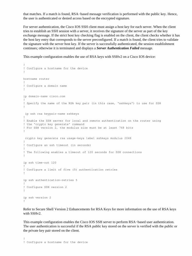
that matches. If a match is found, RSA−based message verification is performed with the public key. Hence,the user is authenticated or denied access based on the encrypted signature.
For server authentication, the Cisco IOS SSH client must assign a host key for each server. When the clienttries to establish an SSH session with a server, it receives the signature of the server as part of the keyexchange message. If the strict host key checking flag is enabled on the client, the client checks whether it hasthe host key entry that corresponds to the server preconfigured. If a match is found, the client tries to validatethe signature with the server host key. If the server is successfully authenticated, the session establishmentcontinues; otherwise it is terminated and displays a Server Authentication Failed message.
This example configuration enables the use of RSA keys with SSHv2 on a Cisco IOS device:
!! Configure a hostname for the device!
hostname router!! Configure a domain name!
ip domain−name cisco.com!! Specify the name of the RSA key pair (in this case, "sshkeys") to use for SSH!
ip ssh rsa keypair−name sshkeys!! Enable the SSH server for local and remote authentication on the router using ! the "crypto key generate" command! For SSH version 2, the modulus size must be at least 768 bits !
crypto key generate rsa usage−keys label sshkeys modulus 2048!! Configure an ssh timeout (in seconds) !! The following enables a timeout of 120 seconds for SSH connections!
ip ssh time−out 120!! Configure a limit of five (5) authentication retries!
ip ssh authentication−retries 5!! Configure SSH version 2!
ip ssh version 2 !
Refer to Secure Shell Version 2 Enhancements for RSA Keys for more information on the use of RSA keyswith SSHv2.
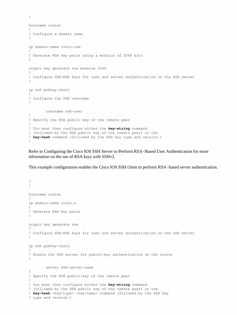
This example configuration enables the Cisco IOS SSH server to perform RSA−based user authentication.The user authentication is successful if the RSA public key stored on the server is verified with the public orthe private key pair stored on the client.
!! Configure a hostname for the device
!
hostname router!! Configure a domain name!
ip domain−name cisco.com!! Generate RSA key pairs using a modulus of 2048 bits!
crypto key generate rsa modulus 2048!! Configure SSH−RSA keys for user and server authentication on the SSH server!
ip ssh pubkey−chain!! Configure the SSH username!
username ssh−user!! Specify the RSA public key of the remote peer!! You must then configure either the key−string command! (followed by the RSA public key of the remote peer) or the ! key−hash command (followed by the SSH key type and version.)!
Refer to Configuring the Cisco IOS SSH Server to Perform RSA−Based User Authentication for moreinformation on the use of RSA keys with SSHv2.
This example configuration enables the Cisco IOS SSH client to perform RSA−based server authentication.
crypto key generate rsa!! Configure SSH−RSA keys for user and server authentication on the SSH server!
ip ssh pubkey−chain!! Enable the SSH server for public−key authentication on the router !
server SSH−server−name!! Specify the RSA public−key of the remote peer !! You must then configure either the key−string command! (followed by the RSA public key of the remote peer) or the ! key−hash <key−type> <key−name> command (followed by the SSH key ! type and version.)
!! Ensure that server authentication takes place − The connection will be ! terminated on a failure!
ip ssh stricthostkeycheck !
Refer to Configuring the Cisco IOS SSH Client to Perform RSA−Based Server Authentication for moreinformation on the use of RSA keys with SSHv2.
Console and AUX Ports
In Cisco IOS devices, console and auxiliary (AUX) ports are asynchronous lines that can be used for local andremote access to a device. You must be aware that console ports on Cisco IOS devices have special privileges.In particular, these privileges allow an administrator to perform the password recovery procedure. In order toperform password recovery, an unauthenticated attacker would need to have access to the console port and theability to interrupt power to the device or to cause the device to crash.
Any method used in order to access the console port of a device must be secured in a manner that is equal tothe security that is enforced for privileged access to a device. Methods used in order to secure access mustinclude the use of AAA, exec−timeout, and modem passwords if a modem is attached to the console.
If password recovery is not required, then an administrator can remove the ability to perform the passwordrecovery procedure using the no service password−recovery global configuration command; however, oncethe no service password−recovery command has been enabled, an administrator can no longer performpassword recovery on a device.
In most situations, the AUX port of a device must be disabled in order to prevent unauthorized access. AnAUX port can be disabled with these commands:
!
line aux 0 transport input none transport output none no exec exec−timeout 0 1 no password!
Control vty and tty Lines
Interactive management sessions in Cisco IOS software use a tty or virtual tty (vty). A tty is a localasynchronous line to which a terminal can be attached for local access to the device or to a modem for dialupaccess to a device. Note that ttys can be used for connections to console ports of other devices. This functionallows a device with tty lines to act as a console server where connections can be established across thenetwork to the console ports of devices connected to the tty lines. The tty lines for these reverse connectionsover the network must also be controlled.
A vty line is used for all other remote network connections supported by the device, regardless of protocol(SSH, SCP, or Telnet are examples). In order to ensure that a device can be accessed via a local or remotemanagement session, proper controls must be enforced on both vty and tty lines. Cisco IOS devices have alimited number of vty lines; the number of lines available can be determined with the show line EXECcommand. When all vty lines are in use, new management sessions cannot be established, which creates aDoS condition for access to the device.
The simplest form of access control to a vty or tty of a device is through the use of authentication on all linesregardless of the device location within the network. This is critical for vty lines because they are accessiblevia the network. A tty line that is connected to a modem that is used for remote access to the device, or a ttyline that is connected to the console port of other devices are also accessible via the network. Other forms ofvty and tty access controls can be enforced with the transport input or access−class configuration commands,with the use of the CoPP and CPPr features, or if you apply access lists to interfaces on the device.
Authentication can be enforced through the use of AAA, which is the recommended method for authenticatedaccess to a device, with the use of the local user database, or by simple password authentication configureddirectly on the vty or tty line.
The exec−timeout command must be used in order to logout sessions on vty or tty lines that are left idle. Theservice tcp−keepalives−in command must also be used in order to enable TCP keepalives on incomingconnections to the device. This ensures that the device on the remote end of the connection is still accessibleand that half−open or orphaned connections are removed from the local IOS device.
Control Transport for vty and tty Lines
A vty and tty should be configured in order to accept only encrypted and secure remote access managementconnections to the device or through the device if it is used as a console server. This section addresses ttysbecause such lines can be connected to console ports on other devices, which allow the tty to be accessibleover the network. In an effort to prevent information disclosure or unauthorized access to the data that istransmitted between the administrator and the device, transport input ssh should be used instead of clear−textprotocols, such as Telnet and rlogin. The transport input none configuration can be enabled on a tty, which ineffect disables the use of the tty line for reverse−console connections.
Both vty and tty lines allow an administrator to connect to other devices. In order to limit the type of transportthat an administrator can use for outgoing connections, use the transport output line configuration command.If outgoing connections are not needed, then transport output none should be used. However, if outgoingconnections are allowed, then an encrypted and secure remote access method for the connection should beenforced through the use of transport output ssh.
Note: IPSec can be used for encrypted and secure remote access connections to a device, if supported. If youuse IPSec, it also adds additional CPU overhead to the device. However, SSH must still be enforced as thetransport even when IPSec is used.
Warning Banners
In some legal jurisdictions, it can be impossible to prosecute and illegal to monitor malicious users unless theyhave been notified that they are not permitted to use the system. One method to provide this notification is toplace this information into a banner message that is configured with the Cisco IOS software banner logincommand.
Legal notification requirements are complex, vary by jurisdiction and situation, and should be discussed withlegal counsel. Even within jurisdictions, legal opinions can differ. In cooperation with counsel, a banner canprovide some or all of the this information:
Notice that the system is to be logged into or used only by specifically authorized personnel andperhaps information about who can authorize use.
•
Notice that any unauthorized use of the system is unlawful and can be subject to civil and criminalpenalties.
•
Notice that any use of the system can be logged or monitored without further notice and that theresulting logs can be used as evidence in court.
•
Specific notices required by local laws.•
From a security point of view, rather than legal, a login banner should not contain any specific informationabout the router name, model, software, or ownership. This information can be abused by malicious users.
Authentication, Authorization, and Accounting
The Authentication, Authorization, and Accounting (AAA) framework is critical in order to secure interactiveaccess to network devices. The AAA framework provides a highly configurable environment that can betailored based on the needs of the network.
TACACS+ Authentication
TACACS+ is an authentication protocol that Cisco IOS devices can use for authentication of managementusers against a remote AAA server. These management users can access the IOS device via SSH, HTTPS,telnet, or HTTP.
TACACS+ authentication, or more generally AAA authentication, provides the ability to use individual useraccounts for each network administrator. When you do not depend on a single shared password, the securityof the network is improved and your accountability is strengthened.
RADIUS is a protocol similar in purpose to TACACS+; however, it only encrypts the password sent acrossthe network. In contrast, TACACS+ encrypts the entire TCP payload, which includes both the username andpassword. For this reason, TACACS+ should be used in preference to RADIUS when TACACS+ is supportedby the AAA server. Refer to TACACS+ and RADIUS Comparison for a more detailed comparison of thesetwo protocols.
TACACS+ authentication can be enabled on a Cisco IOS device with a configuration similar to this example:
!
aaa new−modelaaa authentication login default group tacacs+!
The previous configuration can be used as a starting point for an organization−specific AAA authenticationtemplate. Refer to Authentication, Authorization, and Accounting for more information about theconfiguration of AAA.
A method list is a sequential list that describes the authentication methods to be queried in order toauthenticate a user. Method lists enable you to designate one or more security protocols to be used forauthentication, and thus ensure a backup system for authentication in case the initial method fails. Cisco IOSsoftware uses the first listed method that successfully accepts or rejects a user. Subsequent methods are onlyattempted in cases where earlier methods fail due to server unavailability or incorrect configuration. Refer toNamed Method Lists for Authentication for more information about the configuration of Named MethodLists.
Authentication Fallback
If all configured TACACS+ servers become unavailable, then a Cisco IOS device can rely on secondaryauthentication protocols. Typical configurations include the use of local or enable authentication if allconfigured TACACS+ servers are unavailable.
The complete list of options for on−device authentication includes enable, local, and line. Each of theseoptions has advantages. The use of the enable secret is preferred because the secret is hashed with a one−wayalgorithm that is inherently more secure than the encryption algorithm that is used with the Type 7 passwordsfor line or local authentication.
However, on Cisco IOS software releases that support the use of secret passwords for locally defined users,fallback to local authentication can be desirable. This allows for a locally defined user to be created for one ormore network administrators. If TACACS+ were to become completely unavailable, each administrator canuse their local username and password. Although this action does enhance the accountability of networkadministrators in TACACS+ outages, it significantly increases the administrative burden because local useraccounts on all network devices must be maintained.
This configuration example builds upon the previous TACACS+ authentication example in order to includefallback authentication to the password that is configured locally with the enable secret command:
!
enable secret <password>!
aaa new−modelaaa authentication login default group tacacs+ enable!
Refer to Configuring Authentication for more information on the use of fallback authentication with AAA.
Use of Type 7 Passwords
Originally designed in order to allow quick decryption of stored passwords, Type 7 passwords are not a secureform of password storage. There are many tools available that can easily decrypt these passwords. The use ofType 7 passwords should be avoided unless required by a feature that is in use on the Cisco IOS device.
The removal of passwords of this type can be facilitated through AAA authentication and the use of theEnhanced Password Security feature, which allows secret passwords to be used with users that are locallydefined via the username global configuration command. If you cannot fully prevent the use of Type 7passwords, consider these passwords obfuscated, not encrypted.
See the General Management Plane Hardening section of this document for more information about theremoval of Type 7 passwords.
TACACS+ Command Authorization
Command authorization with TACACS+ and AAA provides a mechanism that permits or denies eachcommand that is entered by an administrative user. When the user enters EXEC commands, Cisco IOS sendseach command to the configured AAA server. The AAA server then uses its configured policies in order topermit or deny the command for that particular user.
This configuration can be added to the previous AAA authentication example in order to implement commandauthorization:
!
aaa authorization exec default group tacacs none
aaa authorization commands 0 default group tacacs noneaaa authorization commands 1 default group tacacs none aaa authorization commands 15 default group tacacs none!
Refer to Configuring Authorization for more information about command authorization.
TACACS+ Command Accounting
When configured, AAA command accounting sends information about each EXEC command that is enteredto the configured TACACS+ servers. The information sent to the TACACS+ server includes the commandexecuted, the date it was executed, and the username of the user who enters the command. Commandaccounting is not supported with RADIUS.
This example configuration enables AAA command accounting for EXEC commands entered at privilegelevels zero, one, and 15. This configuration builds upon previous examples that include configuration of theTACACS servers.
!
aaa accounting exec default start−stop group tacacs aaa accounting commands 0 default start−stop group tacacsaaa accounting commands 1 default start−stop group tacacsaaa accounting commands 15 default start−stop group tacacs!
Refer to Configuring Accounting for more information about the configuration of AAA accounting.
Redundant AAA Servers
The AAA servers that are leveraged in an environment should be redundant and deployed in a fault−tolerantmanner. This helps ensure that interactive management access, such as SSH, is possible if an AAA server isunavailable.
When you design or implement a redundant AAA server solution, remember these considerations:
Availability of AAA servers during potential network failures• Geographically dispersed placement of AAA servers• Load on individual AAA servers in steady−state and failure conditions• Network latency between Network Access Servers and AAA servers• AAA server databases synchronization•
Refer to Deploy the Access Control Servers for more information.
Fortify the Simple Network Management Protocol
This section highlights several methods that can be used in order to secure the deployment of SNMP withinIOS devices. It is critical that SNMP be properly secured in order to protect the confidentiality, integrity, andavailability of both the network data and the network devices through which this data transits. SNMP providesyou with a wealth of information on the health of network devices. This information should be protected frommalicious users that want to leverage this data in order to perform attacks against the network.
SNMP Community Strings
Community strings are passwords that are applied to an IOS device to restrict access, both read−only andread−write access, to the SNMP data on the device. These community strings, as with all passwords, should
be carefully chosen to ensure they are not trivial. Community strings should be changed at regular intervalsand in accordance with network security policies. For example, the strings should be changed when a networkadministrator changes roles or leaves the company.
These configuration lines configure a read−only community string of READONLY and a read−writecommunity string of READWRITE:
!
snmp−server community READONLY ROsnmp−server community READWRITE RW !
Note: The previous community string examples have been chosen in order to clearly explain the use of thesestrings. For production environments, community strings should be chosen with caution and should consist ofa series of alphabetical, numerical, and non−alphanumeric symbols. Refer to Recommendations for CreatingStrong Passwords for more information on the selection of non−trivial passwords.
Refer to IOS SNMP Command Reference for more information about this feature.
SNMP Community Strings with ACLs
In addition to the community string, an ACL should be applied that further restricts SNMP access to a selectgroup of source IP addresses. This configuration restricts SNMP read−only access to end host devices thatreside in the 192.168.100.0/24 address space and restricts SNMP read−write access to only the end hostdevice at 192.168.100.1.
Note: The devices that are permitted by these ACLs require the proper community string in order to access therequested SNMP information.
snmp−server community READONLY RO 98snmp−server community READWRITE RW 99!
Refer to snmp−server community in the Cisco IOS Network Management Command Reference for moreinformation about this feature.
Infrastructure ACLs
Infrastructure ACLs (iACLs) can be deployed in order to ensure that only end hosts with trusted IP addressescan send SNMP traffic to an IOS device. An iACL should contain a policy that denies unauthorized SNMPpackets on UDP port 161.
See the Limiting Access to the Network with Infrastructure ACLs section of this document for moreinformation on the use of iACLs.
SNMP Views
SNMP Views are a security feature that can permit or deny access to certain SNMP MIBs. Once a view iscreated and applied to a community string with the snmp−server community community−string view globalconfiguration commands, if you access MIB data, you are restricted to the permissions that are defined by the
view. When appropriate, you are advised to use views to limit users of SNMP to the data that they require.
This configuration example restricts SNMP access with the community string LIMITED to the MIB data thatis located in the system group:
!
snmp−server view VIEW−SYSTEM−ONLY system include!
snmp−server community LIMITED view VIEW−SYSTEM−ONLY RO!
Refer to Configuring SNMP Support for more information.
SNMP Version 3
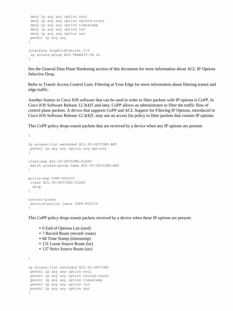
SNMP Version 3 (SNMPv3) is defined by RFC3410, RFC3411, RFC3412, RFC3413, RFC3414, andRFC3415 and is an interoperable standards−based protocol for network management. SNMPv3 providessecure access to devices because it authenticates and optionally encrypts packets over the network. Wheresupported, SNMPv3 can be used in order to add another layer of security when you deploy SNMP. SNMPv3consists of three primary configuration options:
no auth − This mode does not require any authentication nor any encryption of SNMP packets• auth − This mode requires authentication of the SNMP packet without encryption• priv − This mode requires both authentication and encryption (privacy) of each SNMP packet•
An authoritative engine ID must exist in order to use the SNMPv3 security mechanisms − authentication orauthentication and encryption − to handle SNMP packets; by default, the engine ID is generated locally. Theengine ID can be displayed with the show snmp engineID command as shown in this example:
router#show snmp engineID Local SNMP engineID: 80000009030000152BD35496 Remote Engine ID IP−addr Port
Note: If the engineID is changed, all SNMP user accounts must be reconfigured.
The next step is to configure an SNMPv3 group. This command configures a Cisco IOS device for SNMPv3with an SNMP server group AUTHGROUP and enables only authentication for this group with the authkeyword:
!snmp−server group AUTHGROUP v3 auth!
This command configures a Cisco IOS device for SNMPv3 with an SNMP server group PRIVGROUP andenables both authentication and encryption for this group with the priv keyword:
!snmp−server group PRIVGROUP v3 priv!
This command configures an SNMPv3 user snmpv3user with an MD5 authentication password ofauthpassword and a 3DES encryption password of privpassword:
!
snmp−server user snmpv3user PRIVGROUP v3 auth md5 authpassword priv 3des
privpassword!
Note that snmp−server user configuration commands are not displayed in the configuration output of thedevice as required by RFC 3414; therefore, the user password is not viewable from the configuration. In orderto view the configured users, enter the show snmp user command as shown in this example:
Refer to Configuring SNMP Support for more information about this feature.
Management Plane Protection
The Management Plane Protection (MPP) feature in Cisco IOS software can be used in order to help secureSNMP because it restricts the interfaces through which SNMP traffic can terminate on the device. The MPPfeature allows an administrator to designate one or more interfaces as management interfaces. Managementtraffic is permitted to enter a device only through these management interfaces. After MPP is enabled, nointerfaces except designated management interfaces accept network management traffic that is destined to thedevice.
Note that the MPP is a subset of the CPPr feature and requires a version of IOS that supports CPPr. Refer toUnderstanding Control Plane Protection for more information on CPPr.
In this example, MPP is used in order to restrict SNMP and SSH access to only the FastEthernet 0/0 interface:
Refer to Management Plane Protection Feature Guide for more information.
Logging Best Practices
Event logging provides you visibility into the operation of a Cisco IOS device and the network into which it isdeployed. Cisco IOS software provides several flexible logging options that can help achieve the networkmanagement and visibility goals of an organization.
These sections provide some basic logging best practices that can help an administrator leverage loggingsuccessfully while minimizing the impact of logging on a Cisco IOS device.
Send Logs to a Central Location
You are advised to send logging information to a remote syslog server. This makes it possible to correlate andaudit network and security events across network devices more effectively. Note that syslog messages aretransmitted unreliably by UDP and in cleartext. For this reason, any protections that a network affords tomanagement traffic (for example, encryption or out−of−band access) should be extended in order to includesyslog traffic.
This configuration example configures a Cisco IOS device in order to send logging information to a remotesyslog server:
!logging host <ip−address>!
Refer to Identifying Incidents Using Firewall and IOS Router Syslog Events for more information on logcorrelation.
Integrated in 12.4(15)T and originally introduced in 12.0(26)S, the Logging to Local Nonvolatile Storage(ATA Disk) feature enables system logging messages to be saved on an advanced technology attachment(ATA) flash disk. Messages saved on an ATA drive persist after a router is rebooted.
This configuration lines configure 134,217,728 bytes (128 MB) of logging messages to the syslog directory ofthe ATA flash (disk0), specifying a file size of 16,384 bytes:
Before logging messages are written to a file on the ATA disk, Cisco IOS Software checks if there issufficient disk space. If not, the oldest file of logging messages (by timestamp) is deleted, and the current fileis saved. The filename format is log_month:day:year::time.
Note: An ATA flash drive has limited disk space and thus needs to be maintained to avoid overwriting storeddata.
This example shows how to copy logging messages from the router ATA flash disk to an external disk on FTPserver 192.168.1.129 as part of maintenance procedures:
Refer to Logging to Local Nonvolatile Storage (ATA Disk) for more information about this feature.
Logging Level
Each log message that is generated by a Cisco IOS device is assigned one of eight severities that range fromlevel 0, Emergencies, through level 7, Debug. Unless specifically required, you are advised to avoid loggingat level 7. Logging at level 7 produces an elevated CPU load on the device that can lead to device and networkinstability.
The global configuration command logging trap level is used in order to specify which logging messages aresent to remote syslog servers. The level specified indicates the lowest severity message that is sent. Forbuffered logging, the logging buffered level command is used.
This configuration example limits log messages that are sent to remote syslog servers and the local log bufferto severities 6 (informational) through 0 (emergencies):
!
logging trap 6logging buffered 6!
Refer to Troubleshooting, Fault Management, and Logging for more information.
Do Not Log to Console or Monitor Sessions
With Cisco IOS software, it is possible to send log messages to monitor sessions − monitor sessions areinteractive management sessions in which the EXEC command terminal monitor has been issued − and to theconsole. However, this can elevate the CPU load of an IOS device and therefore is not recommended. Instead,you are advised to send logging information to the local log buffer, which can be viewed with the showlogging command.
Use the global configuration commands no logging console and no logging monitor in order to disablelogging to the console and monitor sessions. This configuration example shows the use of these commands:
!
no logging consoleno logging monitor!
Refer to Cisco IOS Network Management Command Reference for more information about globalconfiguration commands.
Use Buffered Logging
Cisco IOS software supports the use of a local log buffer so that an administrator can view locally generatedlog messages. The use of buffered logging is highly recommended versus logging to either the console ormonitor sessions.
There are two configuration options that are relevant when configuring buffered logging: the logging buffersize and the message severities that is stored in the buffer. The size of the logging buffer is configured withthe global configuration command logging buffered size. The lowest severity included in the buffer isconfigured with the logging buffered severity command. An administrator is able to view the contents of thelogging buffer through the show logging EXEC command.
This configuration example includes the configuration of a logging buffer of 16384 bytes, as well as a severityof 6, informational, which indicates that messages at levels 0 (emergencies) through 6 (informational) isstored:
!
logging buffered 16384 6!
Refer to Cisco IOS Network Management Command Reference for more information about buffered logging.
Configure Logging Source Interface
In order to provide an increased level of consistency when you collect and review log messages, you areadvised to statically configure a logging source interface. Accomplished via the logging source−interfaceinterface command, statically configuring a logging source interface ensures that the same IP address appearsin all logging messages that are sent from an individual Cisco IOS device. For added stability, you are advisedto use a loopback interface as the logging source.
This configuration example illustrates the use of the logging source−interface interface global configurationcommand in order to specify that the IP address of the loopback 0 interface be used for all log messages:
!logging source−interface Loopback 0
!
Refer to the Cisco IOS Command Reference for more information.
Configure Logging Timestamps
The configuration of logging timestamps helps you correlate events across network devices. It is important toimplement a correct and consistent logging timestamp configuration to ensure that you are able to correlatelogging data. Logging timestamps should be configured to include the date and time with millisecondprecision and to include the time zone in use on the device.
This example includes the configuration of logging timestamps with millisecond precision within theCoordinated Universal Time (UTC) zone:
If you prefer not to log times relative to UTC, you can configure a specific local time zone and configure thatinformation to be present in generated log messages. This example shows a device configuration for thePacific Standard Time (PST) zone:
Cisco IOS software includes several features that can enable a form of configuration management on a CiscoIOS device. Such features include functionality to archive configurations and to rollback the configuration to aprevious version as well as create a detailed configuration change log.
Configuration Replace and Configuration Rollback
In Cisco IOS Software Release 12.3(7)T and later, the Configuration Replace and Configuration Rollbackfeatures allow you to archive the Cisco IOS device configuration on the device. Stored manually orautomatically, the configurations in this archive can be used in order to replace the current runningconfiguration with the configure replace filename command. This is in contrast to the copy filenamerunning−config command. The configure replace filename command replaces the running configuration asopposed to the merge performed by the copy command.
You are advised to enable this feature on all Cisco IOS devices in the network. Once enabled, an administratorcan cause the current running configuration to be added to the archive with the archive config privilegedEXEC command. The archived configurations can be viewed with the show archive EXEC command.
This example illustrates the configuration of automatic configuration archiving. This example instructs theCisco IOS device to store archived configurations as files named archived−config−N on the disk0: filesystem, to maintain a maximum of 14 backups, and to archive once per day (1440 minutes) and when anadministrator issues the write memory EXEC command.
!
archive path disk0:archived−config
maximum 14 time−period 1440 write−memory!
Although the configuration archive functionality can store up to 14 backup configurations, you are advised toconsider the space requirements before you use the maximum command.
Exclusive Configuration Change Access
Added to Cisco IOS Software Release 12.3(14)T, the Exclusive Configuration Change Access feature ensuresthat only one administrator makes configuration changes to a Cisco IOS device at a given time. This featurehelps eliminate the undesirable impact of simultaneous changes made to related configuration components.This feature is configured with the global configuration command configuration mode exclusive mode andoperates in one of two modes: auto and manual. In auto−mode, the configuration automatically locks when anadministrator issues the configure terminal EXEC command. In manual mode, the administrator uses theconfigure terminal lock command in order to lock the configuration when it enters configuration mode.
This example illustrates the configuration of this feature for automatic configuration locking:
!configuration mode exclusive auto!
Cisco IOS Software Resilient Configuration
Added in Cisco IOS Software Release 12.3(8)T, the Resilient Configuration feature makes it possible tosecurely store a copy of the Cisco IOS software image and device configuration that is currently used by aCisco IOS device. When this feature is enabled, it is not possible to alter or remove these backup files. Youare advised to enable this feature in order to prevent both inadvertent and malicious attempts to delete thesefiles.
!secure boot−imagesecure boot−config!
Once this feature is enabled, it is possible to restore a deleted configuration or Cisco IOS software image. Thecurrent running state of this feature can be displayed with the show secure boot EXEC command.
Digitally Signed Cisco Software
Added in Cisco IOS Software Release 15.0(1)M for the Cisco 1900, 2900, and 3900 Series routers, theDigitally Signed Cisco Software feature facilitates the use of Cisco IOS Software that is digitally signed andthus trusted, with the use of secure asymmetrical (public−key) cryptography.
A digitally signed image carries an encrypted (with a private key) hash of itself. Upon check, the devicedecrypts the hash with the corresponding public key from the keys it has in its key store and also calculates itsown hash of the image. If the decrypted hash matches the calculated image hash, the image has not beentampered with and can be trusted.
Digitally signed Cisco software keys are identified by the type and version of the key. A key can be a special,production, or rollover key type. Production and special key types have an associated key version thatincrements alphabetically whenever the key is revoked and replaced. ROMMON and regular Cisco IOSimages are both signed with a special or production key when you use the Digitally Signed Cisco Softwarefeature. The ROMMON image is upgradable and must be signed with the same key as the special orproduction image that is loaded.
This command verifies the integrity of image c3900−universalk9−mz.SSA in flash with the keys in the devicekey store:
show software authenticity file flash0:c3900−universalk9−mz.SSA
The Digitally Signed Cisco Software feature was also integrated in Cisco IOS XE Release 3.1.0.SG for theCisco Catalyst 4500 E−Series Switches.
Refer to Digitally Signed Cisco Software for more information about this feature.
In Cisco IOS Software Release 15.1(1)T and later, Key Replacement for Digitally Signed Cisco Software wasintroduced. Key replacement and revocation replaces and removes a key that is used for a Digitally SignedCisco Software check from a platform's key storage. Only special and production keys can be revoked in theevent of a key compromise.
A new (special or production) key for a (special or production) image comes in a (production or revocation)image that is used in order to revoke the previous special or production key. The revocation image integrity isverified with a rollover key that comes prestored on the platform. A rollover key does not change. When yourevoke a production key, after the revocation image is loaded, the new key it carries is added to the key storeand the corresponding old key can be revoked as long as ROMMON image is upgraded and the newproduction image is booted. When you revoke a special key, a production image is loaded. This image addsthe new special key and can revoke the old special key. After you upgrade ROMMON, the new special imagecan be booted.
This example describes revocation of a special key. These commands add the new special key to the key storefrom the current production image, copy a new ROMMON image (C3900_rom−monitor.srec.SSB) to thestorage area (usbflash0, upgrade the ROMMON file, and revoke the old special key:
A new special image (c3900−universalk9−mz.SSB) can then be copied to the flash to be loaded and thesignature of the image is verified with the newly added special key (.SSB):
Key revocation and replacement is not supported on Catalyst 4500 E−Series Switches that run Cisco IOS XESoftware, although these switches do support the Digitally Signed Cisco Software feature.
Refer to the Digitally Signed Cisco Software Key Revocation and Replacement section of the DigitallySigned Cisco Software guide for more information about this feature.
Configuration Change Notification and Logging
The Configuration Change Notification and Logging feature, added in Cisco IOS Software Release 12.3(4)T,makes it possible to log the configuration changes made to a Cisco IOS device. The log is maintained on theCisco IOS device and contains the user information of the individual who made the change, the configurationcommand entered, and the time that the change was made. This functionality is enabled with the loggingenable configuration change logger configuration mode command. The optional commands hidekeys andlogging size entries are used in order to improve the default configuration becuase they prevent the logging ofpassword data and increase the length of the change log.
You are advised to enable this functionality so that the configuration change history of a Cisco IOS device canbe more easily understood. Additionally, you are advised to use the notify syslog configuration command inorder to enable the generation of syslog messages when a configuration change is made.
After the Configuration Change Notification and Logging feature has been enabled, the privileged EXECcommand show archive log config all can be used in order to view the configuration log.
Control Plane
Control plane functions consist of the protocols and processes that communicate between network devices inorder to move data from source to destination. This includes routing protocols such as the Border GatewayProtocol, as well as protocols like ICMP and the Resource Reservation Protocol (RSVP).
It is important that events in the management and data planes do not adversely affect the control plane. Shoulda data plane event such as a DoS attack impact the control plane, the entire network can become unstable.This information about Cisco IOS software features and configurations can help ensure the resilience of thecontrol plane.
General Control Plane Hardening
Protection of the control plane of a network device is critical because the control plane ensures that themanagement and data planes are maintained and operational. If the control plane were to become unstableduring a security incident, it can be impossible for you to recover the stability of the network.
In many cases, you can disable the reception and transmission of certain types of messages on an interface inorder to minimize the amount of CPU load that is required to process unneeded packets.
IP ICMP Redirects
An ICMP redirect message can be generated by a router when a packet is received and transmitted on thesame interface. In this situation, the router forwards the packet and sends an ICMP redirect message back tothe sender of the original packet. This behavior allows the sender to bypass the router and forward futurepackets directly to the destination (or to a router closer to the destination). In a properly functioning IPnetwork, a router sends redirects only to hosts on its own local subnets. In other words, ICMP redirects shouldnever go beyond a Layer 3 boundary.
There are two types of ICMP redirect messages: redirect for a host address and redirect for an entire subnet. Amalicious user can exploit the ability of the router to send ICMP redirects by continually sending packets tothe router, which forces the router to respond with ICMP redirect messages, and results in an adverse impacton the CPU and performance of the router. In order to prevent the router from sending ICMP redirects, use theno ip redirects interface configuration command.
ICMP Unreachables
Filtering with an interface access list elicits the transmission of ICMP unreachable messages back to thesource of the filtered traffic. The generation of these messages can increase CPU utilization on the device. InCisco IOS software, ICMP unreachable generation is limited to one packet every 500 milliseconds by default.ICMP unreachable message generation can be disabled with the interface configuration command no ipunreachables. ICMP unreachable rate limiting can be changed from the default with the global configurationcommand ip icmp rate−limit unreachable interval−in−ms.
Proxy ARP
Proxy ARP is the technique in which one device, usually a router, answers ARP requests that are intended foranother device. By "faking" its identity, the router accepts responsibility for routing packets to the realdestination. Proxy ARP can help machines on a subnet reach remote subnets without configuring routing or adefault gateway. Proxy ARP is defined in RFC 1027 .
There are several disadvantages to proxy ARP utilization. It can result in an increase in the amount of ARPtraffic on the network segment and resource exhaustion and man−in−the−middle attacks. Proxy ARP presentsa resource exhaustion attack vector because each proxied ARP request consumes a small amount of memory.An attacker can be able to exhaust all available memory if it sends a large number of ARP requests.
Man−in−the−middle attacks enable a host on the network to spoof the MAC address of the router, whichresults in unsuspecting hosts sending traffic to the attacker. Proxy ARP can be disabled with the interfaceconfiguration command no ip proxy−arp.
Refer to Enabling Proxy ARP for more information on this feature.
Limit CPU Impact of Control Plane Traffic
Protection of the control plane is critical. Because application performance and end−user experience cansuffer without the presence of data and management traffic, the survivability of the control plane ensures thatthe other two planes are maintained and operational.
Understand Control Plane Traffic
In order properly protect the control plane of the Cisco IOS device, it is essential to understand the types oftraffic that is process switched by the CPU. Process switched traffic normally consists of two different typesof traffic. The first type of traffic is directed to the Cisco IOS device and must be handled directly by theCisco IOS device CPU. This traffic consists of this category:
Receive adjacency traffic − This traffic contains an entry in the Cisco Express Forwarding (CEF)table whereby the next router hop is the device itself, which is indicated by the term receive in theshow ip cef CLI output. This indication is the case for any IP address that requires direct handling bythe Cisco IOS device CPU, which includes interface IP addresses, multicast address space, andbroadcast address space.
•
The second type of traffic that is handled by the CPU is data plane traffic − traffic with a destination beyondthe Cisco IOS device itself − which requires special processing by the CPU. Although not an exhaustive list ofCPU impacting data plane traffic, these types of traffic are process switched and can therefore affect theoperation of the control plane:
Access Control List logging − ACL logging traffic consists of any packets that are generated due to amatch (permit or deny) of an ACE on which the log keyword is used.
•
Unicast Reverse Path Forwarding (Unicast RPF) − Unicast RPF, used in conjunction with an ACL,can result in the process switching of certain packets.
•
IP Options − Any IP packets with options included must be processed by the CPU.•
Fragmentation − Any IP packet that requires fragmentation must be passed to the CPU forprocessing.
•
Time−to−live (TTL) Expiry − Packets which have a TTL value less than or equal to one requireInternet Control Message Protocol Time Exceeded (ICMP Type 11, Code 0) messages to be sent,which results in CPU processing.
•
ICMP Unreachables − Packets that result in ICMP unreachable messages due to routing, MTU, orfiltering is processed by the CPU.
•
Traffic Requiring an ARP Request − Destinations for which an ARP entry does not exist requireprocessing by the CPU.
•
Non−IP Traffic − All non−IP traffic is processed by the CPU.•
This list details several methods to determine which types of traffic are being processed by the Cisco IOSdevice CPU:
The show ip cef command provides the next−hop information for each IP prefix that is contained inthe CEF table. As indicated previously, entries that contain receive as the "Next Hop" are consideredreceive adjacencies and indicate that traffic must be sent directly to the CPU.
•
The show interface switching command provides information on the number of packets that areprocess switched by a device.
•
The show ip traffic command provides information on the number of IP packets:
with a local destination (that is, receive adjacency traffic)♦ with options♦ that require fragmentation♦ that are sent to broadcast address space♦ that are sent to multicast address space♦
•
Receive adjacency traffic can be identified through the use of the show ip cache flow command. Anyflows that are destined to the Cisco IOS device has a Destination Interface (DstIf) of local.
•
Control Plane Policing can be used in order to identify the type and rate of traffic that reaches thecontrol plane of the Cisco IOS device. Control plane policing can be performed through the use ofgranular classification ACLs, logging, and the use of the show policy−map control−plane command.
•
Infrastructure ACLs
Infrastructure ACLs (iACLs) limit external communication to the devices of the network. Infrastructure ACLsare extensively covered in the Limit Access to the Network with Infrastructure ACLs section of thisdocument.
You are advised to implement iACLs in order to protect the control plane of all network devices.
Receive ACLs
For distributed platforms, Receive ACLs (rACLs) can be an option for Cisco IOS Software Releases12.0(21)S2 for the 12000 (GSR), 12.0(24)S for the 7500, and 12.0(31)S for the 10720. The rACL protects thedevice from harmful traffic before the traffic impacts the route processor. Receive ACLs are designed to onlyprotect the device on which it is configured and transit traffic is not affected by an rACL. As a result, thedestination IP address any that is used in the example ACL entries below only refers to the physical or virtualIP addresses of the router. Receive ACLs are also considered a network security best practice and should beconsidered as a long−term addition to good network security.
This is the receive path ACL that is written to permit SSH (TCP port 22) traffic from trusted hosts on the192.168.100.0/24 network:
!!−−− Permit SSH from trusted hosts allowed to the device.!
access−list 151 permit tcp 192.168.100.0 0.0.0.255 any eq 22!!−−− Deny SSH from all other sources to the RP.!
access−list 151 deny tcp any any eq 22!!−−− Permit all other traffic to the device.!−−− according to security policy and configurations.!
access−list 151 permit ip any any!!−−− Apply this access list to the receive path.!
ip receive access−list 151!
Refer to GSR: Receive Access Control Lists in order to help identify and allow legitimate traffic to a deviceand deny all unwanted packets.
Control Plane Policing
The Control Plane Policing (CoPP) feature can also be used in order to restrict IP packets that are destined tothe infrastructure device. In this example, only SSH traffic from trusted hosts is permitted to reach the CiscoIOS device CPU.
Note: Dropping traffic from unknown or untrusted IP addresses can prevent hosts with dynamically−assignedIP addresses from connecting to the Cisco IOS device.
!
access−list 152 deny tcp <trusted−addresses> <mask> any eq 22access−list 152 permit tcp any any eq 22access−list 152 deny ip any any!
class−map match−all COPP−KNOWN−UNDESIRABLE match access−group 152!
policy−map COPP−INPUT−POLICY class COPP−KNOWN−UNDESIRABLE
In the previous CoPP example, the ACL entries that match the unauthorized packets with the permit actionresult in a discard of these packets by the policy−map drop function, while packets that match the deny actionare not affected by the policy−map drop function.
CoPP is available in Cisco IOS Software Release trains 12.0S, 12.2SX, 12.2S, 12.3T, 12.4, and 12.4T.
Refer to Deploying Control Plane Policing for more information on the configuration and use of the CoPPfeature.
Control Plane Protection
Control Plane Protection (CPPr), introduced in Cisco IOS Software Release 12.4(4)T, can be used in order torestrict or police control plane traffic that is destined to the CPU of the Cisco IOS device. While similar toCoPP, CPPr has the ability to restrict traffic with finer granularity. CPPr divides the aggregate control planeinto three separate control plane categories known as subinterfaces. Subinterfaces exist for Host, Transit, andCEF−Exception traffic categories. In addition, CPPr includes these control plane protection features:
Port−filtering feature − This feature provides for policing and dropping of packets that are sent toclosed or non−listening TCP or UDP ports.
•
Queue−thresholding feature − This feature limits the number of packets for a specified protocol thatare allowed in the control−plane IP input queue.
•
Refer to Control Plane Protection and Understanding Control Plane Protection (CPPr) for more informationon the configuration and use of the CPPr feature.
Hardware Rate Limiters
The Cisco Catalyst 6500 Series Supervisor Engine 32 and Supervisor Engine 720 support platform−specific,hardware−based rate limiters (HWRLs) for special networking scenarios. These hardware rate limiters arereferred to as special−case rate limiters because they cover a specific predefined set of IPv4, IPv6, unicast,and multicast DoS scenarios. HWRLs can protect the Cisco IOS device from a variety of attacks that requirepackets to be processed by the CPU.
There are several HWRLs that are enabled by default. Refer to PFC3 Hardware−based Rate Limiter DefaultSettings for more information.
Refer to Hardware−Based Rate Limiters on the PFC3 for more information about HWRLs.
Secure BGP
The Border Gateway Protocol (BGP) is the routing foundation of the Internet. As such, any organization withmore than modest connectivity requirements often uses BGP. BGP is often targeted by attackers because of itsubiquity and the ?set and forget? nature of BGP configurations in smaller organizations. However, there aremany BGP−specific security features that can be leveraged to increase the security of a BGP configuration.
This provides an overview of the most important BGP security features. Where appropriate, configurationrecommendations are made.
TTL−based Security Protections
Each IP packet contains a 1−byte field known as the Time to Live (TTL). Each device that an IP packettraverses decrements this value by one. The starting value varies by operating system and typically rangesfrom 64 to 255. A packet is dropped when its TTL value reaches zero.
Known as both the Generalized TTL−based Security Mechanism (GTSM) and BGP TTL Security Hack(BTSH), a TTL−based security protection leverages the TTL value of IP packets in order to ensure that theBGP packets that are received are from a directly connected peer. This feature often requires coordinationfrom peering routers; however, once enabled, it can completely defeat many TCP−based attacks against BGP.
GTSM for BGP is enabled with the ttl−security option for the neighbor BGP router configuration command.This example illustrates the configuration of this feature:
As BGP packets are received, the TTL value is checked and must be greater than or equal to 255 minus thehop−count specified.
BGP Peer Authentication with MD5
Peer authentication with MD5 creates an MD5 digest of each packet sent as part of a BGP session.Specifically, portions of the IP and TCP headers, TCP payload, and a secret key are used in order to generatethe digest.
The created digest is then stored in TCP option Kind 19, which was created specifically for this purpose byRFC 2385 . The receiving BGP speaker uses the same algorithm and secret key in order to regenerate themessage digest. If the received and computed digests are not identical, the packet is discarded.
Peer authentication with MD5 is configured with the password option to the neighbor BGP routerconfiguration command. The use of this command is illustrated as follows:
Refer to Neighbor Router Authentication for more information about BGP peer authentication with MD5.
Configure Maximum Prefixes
BGP prefixes are stored by a router in memory. The more prefixes that a router must hold, the more memorythat BGP must consume. In some configurations, a subset of all Internet prefixes can be stored, such as inconfigurations that leverage only a default route or routes for a provider?s customer networks.
In order to prevent memory exhaustion, it is important to configure the maximum number of prefixes that isaccepted on a per−peer basis. It is recommended that a limit be configured for each BGP peer.
When you configure this feature with the neighbor maximum−prefix BGP router configuration command,
one argument is required: the maximum number of prefixes that are accepted before a peer is shutdown.Optionally, a number from 1 to 100 can also be entered. This number represents the percentage of themaximum prefixes value at which point a log message is sent.
Refer to Configuring the BGP Maximum−Prefix Feature for more information about per−peer maximumprefixes.
Filter BGP Prefixes with Prefix Lists
Prefix lists allow a network administrator to permit or deny specific prefixes that are sent or received viaBGP. Prefix lists should be used where possible in order to ensure network traffic is sent over the intendedpaths. Prefix lists should be applied to each eBGP peer in both the inbound and outbound directions.
Configured prefix lists limit the prefixes that are sent or received to those specifically permitted by the routingpolicy of a network. If this is not feasible due to the large number of prefixes received, a prefix list should beconfigured to specifically block known bad prefixes. These known bad prefixes include unallocated IPaddress space and networks that are reserved for internal or testing purposes by RFC 3330. Outbound prefixlists should be configured to specifically permit only the prefixes that an organization intends to advertise.
This configuration example uses prefix lists to limit the routes that are learned and advertised. Specifically,only a default route is allowed inbound by prefix list BGP−PL−INBOUND, and the prefix 192.168.2.0/24 isthe only route allowed to be advertised by BGP−PL−OUTBOUND.
Refer to Connecting to a Service Provider Using External BGP for complete coverage of BGP prefix filtering.
Filter BGP Prefixes with Autonomous System Path Access Lists
BGP autonomous system (AS) path access lists allows the user to filter received and advertised prefixes basedon the AS−path attribute of a prefix. This can be used in conjunction with prefix lists in order to establish arobust set of filters.
This configuration example uses AS path access lists in order to restrict inbound prefixes to those originatedby the remote AS and outbound prefixes to those originated by the local autonomous system. Prefixes that aresourced from all other autonomous systems are filtered and not installed in the routing table.
The ability of a network to properly forward traffic and recover from topology changes or faults is dependenton an accurate view of the topology. You can often run an Interior Gateway Protocol (IGP) in order providethis view. By default, IGPs are dynamic and discover additional routers that communicate with the particularIGP in use. IGPs also discover routes that can be used during a network link failure.
These subsections provide an overview of the most important IGP security features. Recommendations andexamples that cover Routing Information Protocol Version 2 (RIPv2), Enhanced Interior Gateway RoutingProtocol (EIGRP), and Open Shortest Path First (OSPF) are provided when appropriate.
Routing Protocol Authentication and Verification with Message Digest 5
Failure to secure the exchange of routing information allows an attacker to introduce false routing informationinto the network. By using password authentication with routing protocols between routers, you can aid thesecurity of the network. However, because this authentication is sent as cleartext, it can be simple for anattacker to subvert this security control.
By adding MD5 hash capabilities to the authentication process, routing updates no longer contain cleartextpasswords, and the entire contents of the routing update is more resistant to tampering. However, MD5authentication is still susceptible to brute force and dictionary attacks if weak passwords are chosen. You areadvised to use passwords with sufficient randomization. Since MD5 authentication is much more secure whencompared to password authentication, these examples are specific to MD5 authentication. IPSec can also beused in order to validate and secure routing protocols, but these examples do not detail its use.
EIGRP and RIPv2 utilize Key Chains as part of the configuration. Refer to key for more information on theconfiguration and use of Key Chains.
This is an example configuration for EIGRP router authentication using MD5:
interface <interface> ip rip authentication mode md5 ip rip authentication key−chain <key−name>!
This is an example configuration for OSPF router authentication using MD5. OSPF does not utilize KeyChains.
!
interface <interface> ip ospf message−digest−key <key−id> md5 <password>!
router ospf <process−id> network 10.0.0.0 0.255.255.255 area 0 area 0 authentication message−digest!
Refer to Configuring OSPF for more information.
Passive−Interface Commands
Information leaks, or the introduction of false information into an IGP, can be mitigated through use of thepassive−interface command that assists in controlling the advertisement of routing information. You areadvised not to advertise any information to networks that are outside your administrative control.
This example demonstrates usage of this feature:
!
router eigrp <as−number> passive−interface default no passive−interface <interface>!
Route Filtering
In order to reduce the possibility that you introduce false routing information in the network, you must useRoute Filtering. Unlike the passive−interface router configuration command, routing occurs on interfacesonce route filtering is enabled, but the information that is advertised or processed is limited.
For EIGRP and RIP, usage of the distribute−list command with the out keyword limits what information isadvertised, while usage of the in keyword limits what updates are processed. The distribute−list command isavailable for OSPF, but it does not prevent a router from propagating filtered routes. Instead, the areafilter−list command can be used.
This EIGRP example filters outbound advertisements with the distribute−list command and a prefix list:
!
ip prefix−list <list−name> seq 10 permit <prefix> !
router eigrp <as−number> passive−interface default no passive−interface <interface> distribute−list prefix <list−name> out <interface>!
This EIGRP example filters inbound updates with a prefix list:
!
ip prefix−list <list−name> seq 10 permit <prefix> !
router eigrp <as−number> passive−interface default no passive−interface <interface> distribute−list prefix <list−name> in <interface>!
Refer to Configuring IP Routing Protocol−Independent Features for more information about how to controlthe advertising and processing of routing updates.
This OSPF example uses a prefix list with the OSPF−specific area filter−list command:
!
ip prefix−list <list−name> seq 10 permit <prefix> !
router ospf <process−id> area <area−id> filter−list prefix <list−name> in !
Routing Process Resource Consumption
Routing Protocol prefixes are stored by a router in memory, and resource consumption increases withadditional prefixes that a router must hold. In order to prevent resource exhaustion, it is important to configurethe routing protocol to limit resource consumption. This is possible with OSPF if you use the Link StateDatabase Overload Protection feature.
This example demonstrates configuration of the OSPF Link State Database Overload Protection feature:
Refer to Limiting the Number of Self−Generating LSAs for an OSPF Process for more information on OSPFLink State Database Overload Protection.
Secure First Hop Redundancy Protocols
First Hop Redundancy Protocols (FHRPs) provide resiliency and redundancy for devices that act as defaultgateways. This situation and these protocols are commonplace in environments where a pair of Layer 3devices provides default gateway functionality for a network segment or set of VLANs that contain servers orworkstations.
The Gateway Load−Balancing Protocol (GLBP), Hot Standby Router Protocol (HSRP), and Virtual RouterRedundancy Protocol (VRRP) are all FHRPs. By default, these protocols communicate with unauthenticatedcommunications. This kind of communication can allow an attacker to pose as an FHRP−speaking device toassume the default gateway role on the network. This takeover would allow an attacker to perform aman−in−the−middle attack and intercept all user traffic that exits the network.
In order to prevent this type of attack, all FHRPs that are supported by Cisco IOS software include anauthentication capability with either MD5 or text strings. Because of the threat posed by unauthenticatedFHRPs, it is recommended that instances of these protocols use MD5 authentication. This configurationexample demonstrates the use of GLBP, HSRP, and VRRP MD5 authentication:
Although the data plane is responsible for moving data from source to destination, within the context ofsecurity, the data plane is the least important of the three planes. It is for this reason that it is important toprotect the management and control planes in preference over the data plane when you secure a networkdevice .
However, within the data plane itself, there are many features and configuration options that can help securetraffic. These sections detail these features and options such that you can more easily secure your network.
General Data Plane Hardening
The vast majority of data plane traffic flows across the network as determined by the network?s routingconfiguration. However, IP network functionality exists to alter the path of packets across the network.Features such as IP Options, specifically the source routing option, form a security challenge in today?snetworks.
The use of Transit ACLs is also relevant to the hardening of the data plane. See the Filter Transit Traffic withTransit ACLs section of this document for more information.
IP Options Selective Drop
There are two security concerns presented by IP options. Traffic that contains IP options must beprocess−switched by Cisco IOS devices, which can lead to elevated CPU load. IP options also include thefunctionality to alter the path that traffic takes through the network, which potentially allows it to subvertsecurity controls.
Due to these concerns, the global configuration command ip options {drop | ignore} has been added to CiscoIOS Software Releases 12.3(4)T, 12.0(22)S, and 12.2(25)S. In the first form of this command, ip optionsdrop, all IP packets that contain IP options that are received by the Cisco IOS device are dropped. Thisprevents both the elevated CPU load and possible subversion of security controls that IP options can enable.
The second form of this command, ip options ignore, configures the Cisco IOS device to ignore IP optionsthat are contained in received packets. While this does mitigate the threats related to IP options for the localdevice, it is possible that downstream devices could be affected by the presence of IP options. It is for thisreason that the drop form of this command is highly recommended. This is demonstrated in the configurationexample:
!ip options drop!
Note that some protocols, for example the RSVP, make legitimate use of IP options. The functionality ofthese protocols is impacted by this command.
Once IP Options Selective Drop has been enabled, the show ip traffic EXEC command can be used in order todetermine the number of packets that are dropped due to the presence of IP options. This information ispresent in the forced drop counter.
Refer to ACL IP Options Selective Drop for more information about this feature.
Disable IP Source Routing
IP source routing leverages the Loose Source Route and Record Route options in tandem or the Strict SourceRoute along with the Record Route option to enable the source of the IP datagram to specify the network patha packet takes. This functionality can be used in attempts to route traffic around security controls in thenetwork.
If IP options have not been completely disabled via the IP Options Selective Drop feature, it is important thatIP source routing is disabled. IP source routing, which is enabled by default in all Cisco IOS SoftwareReleases, is disabled via the no ip source−route global configuration command. This configuration exampleillustrates the use of this command:
!no ip source−route!
Disable ICMP Redirects
ICMP redirects are used in order to inform a network device of a better path to an IP destination. By default,the Cisco IOS software sends a redirect if it receives a packet that must be routed through the interface it wasreceived.
In some situations, it might be possible for an attacker to cause the Cisco IOS device to send many ICMPredirect messages, which results in an elevated CPU load. For this reason, it is recommended that thetransmission of ICMP redirects be disabled. ICMP redirects are disabled with the interface configuration no ipredirects command , as shown in the example configuration:
!
interface FastEthernet 0 no ip redirects!
Disable or Limit IP Directed Broadcasts
IP Directed Broadcasts make it possible to send an IP broadcast packet to a remote IP subnet. Once it reachesthe remote network, the forwarding IP device sends the packet as a Layer 2 broadcast to all stations on the
subnet. This directed broadcast functionality has been leveraged as an amplification and reflection aid inseveral attacks, including the smurf attack.
Current versions of Cisco IOS software have this functionality disabled by default; however, it can be enabledvia the ip directed−broadcast interface configuration command. Releases of Cisco IOS software prior to 12.0have this functionality enabled by default.
If a network absolutely requires directed broadcast functionality, its use should be controlled. This is possiblewith the use of an access control list as an option to the ip directed−broadcast command. This configurationexample limits directed broadcasts to those UDP packets that originate at a trusted network, 192.168.1.0/24:
interface FastEthernet 0 ip directed−broadcast 100!
Filter Transit Traffic with Transit ACLs
It is possible to control what traffic transits the network with the use of transit ACLs (tACLs). This is incontrast to infrastructure ACLs that seek to filter traffic that is destined to the network itself. The filteringprovided by tACLs is beneficial when it is desirable to filter traffic to a particular group of devices or trafficthat transits the network.
This type of filtering is traditionally performed by firewalls. However, there are instances where it may bebeneficial to perform this filtering on a Cisco IOS device in the network, for example, where filtering must beperformed but no firewall is present.
Transit ACLs are also an appropriate place in which to implement static anti−spoofing protections. See theAnti−Spoofing Protections section of this document for more information.
Refer to Transit Access Control Lists: Filtering at Your Edge for more information about tACLs.
ICMP Packet Filtering
The Internet Control Message Protocol (ICMP) was designed as a control protocol for IP. As such, themessages it conveys can have far reaching ramifications on the TCP and IP protocols in general. ICMP is usedby the network troubleshooting tools ping and traceroute, as well as by Path MTU Discovery; however,external ICMP connectivity is rarely needed for the proper operation of a network.
Cisco IOS software provides functionality to specifically filter ICMP messages by name or type and code.This example ACL allows ICMP from trusted networks while it blocks all ICMP packets from other sources:
!
ip access−list extended ACL−TRANSIT−IN!!−−− Permit ICMP packets from trusted networks only!
permit icmp host <trusted−networks> any !!−−− Deny all other IP traffic to any network device!
deny icmp any any!
Filter IP Fragments
As detailed previously in the Limit Access to the Network with Infrastructure ACLs section of this document,the filtering of fragmented IP packets can pose a challenge to security devices.
Because of the nonintuitive nature of fragment handling, IP fragments are often inadvertently permitted byACLs. Fragmentation is also often used in attempts to evade detection by intrusion detection systems. It is forthese reasons that IP fragments are often used in attacks and should be explicitly filtered at the top of anyconfigured tACLs. The ACL below includes comprehensive filtering of IP fragments. The functionalityillustrated in this example must be used in conjunction with the functionality of the previous examples:
!
ip access−list extended ACL−TRANSIT−IN!!−−− Deny IP fragments using protocol−specific ACEs to aid in !−−− classification of attack traffic!
deny tcp any any fragments deny udp any any fragments deny icmp any any fragments deny ip any any fragments!
Refer to Access Control Lists and IP Fragments for more information about ACL handling of fragmented IPpackets.
ACL Support for Filtering IP Options
In Cisco IOS Software Release 12.3(4)T and later, Cisco IOS software supports the use of ACLs to filter IPpackets based on the IP options that are contained in the packet. The presence of IP options within a packetmight indicate an attempt to subvert security controls in the network or otherwise alter the transitcharacteristics of a packet. It is for these reasons that packets with IP options should be filtered at the edge ofthe network.
This example must be used with the content from previous examples to include complete filtering of IPpackets that contain IP options:
!
ip access−list extended ACL−TRANSIT−IN!!−−− Deny IP packets containing IP options!
deny ip any any option any−options!
Anti−Spoofing Protections
Many attacks use source IP address spoofing to be effective or to conceal the true source of an attack andhinder accurate traceback. Cisco IOS software provides Unicast RPF and IP Source Guard (IPSG) in order todeter attacks that rely on source IP address spoofing. In addition, ACLs and null routing are often deployed asa manual means of spoofing prevention.
IP Source Guard works to minimize spoofing for networks that are under direct administrative control byperforming switch port, MAC address, and source address verification. Unicast RPF provides source networkverification and can reduce spoofed attacks from networks that are not under direct administrative control.Port Security can be used in order to validate MAC addresses at the access layer. Dynamic AddressResolution Protocol (ARP) Inspection (DAI) mitigates attack vectors that use ARP poisoning on localsegments.
Unicast RPF
Unicast RPF enables a device to verify that the source address of a forwarded packet can be reached throughthe interface that received the packet. You must not rely on Unicast RPF as the only protection againstspoofing. Spoofed packets could enter the network through a Unicast RPF−enabled interface if an appropriatereturn route to the source IP address exists. Unicast RPF relies on you to enable Cisco Express Forwarding oneach device and is configured on a per−interface basis.
Unicast RPF can be configured in one of two modes: loose or strict. In cases where there is asymmetricrouting, loose mode is preferred because strict mode is known to drop packets in these situations. Duringconfiguration of the ip verify interface configuration command, the keyword any configures loose mode whilethe keyword rx configures strict mode.
This example illustrates configuration of this feature:
!
ip cef!
interface <interface> ip verify unicast source reachable−via <mode>!
Refer to Understanding Unicast Reverse Path Forwarding for more information about the configuration anduse of Unicast RPF.
IP Source Guard
IP Source Guard is an effective means of spoofing prevention that can be used if you have control over Layer2 interfaces. IP Source Guard uses information from DHCP snooping to dynamically configure a port accesscontrol list (PACL) on the Layer 2 interface, denying any traffic from IP addresses that are not associated inthe IP source binding table.
IP Source Guard can be applied to Layer 2 interfaces belonging to DHCP snooping−enabled VLANs. Thesecommands enable DHCP snooping:
!
ip dhcp snoopingip dhcp snooping vlan <vlan−range>!
After DHCP snooping is enabled, these commands enable IPSG:
!interface <interface−id> ip verify source !
Port security can be enabled with the ip verify source port security interface configuration command. Thisrequires the global configuration command ip dhcp snooping information option; additionally, the DHCPserver must support DHCP option 82.
Refer to Configuring DHCP features and IP Source Guard for more information on this feature.
Port Security
Port Security is used in order to mitigate MAC address spoofing at the access interface. Port Security can usedynamically learned (sticky) MAC addresses to ease in the initial configuration. Once port security hasdetermined a MAC violation, it can use one of four violation modes. These modes are protect, restrict,shutdown, and shutdown VLAN. In instances when a port only provides access for a single workstation withthe use of standard protocols, a maximum number of one may be sufficient. Protocols that leverage virtualMAC addresses such as HSRP do not function when the maximum number is set to one.
Refer to Configuring Port Security for more information about the Port Security confuration.
Dynamic ARP Inspection
Dynamic ARP Inspection (DAI) can be used in order to mitigate ARP poisoning attacks on local segments.An ARP poisoning attack is a method in which an attacker sends falsified ARP information to a localsegment. This information is designed in order to corrupt the ARP cache of other devices. Often an attackeruses ARP poisoning in order to perform a man−in−the−middle attack.
DAI intercepts and validates the IP−to−MAC address relationship of all ARP packets on untrusted ports. InDHCP environments, DAI uses the data that is generated by the DHCP snooping feature. ARP packets thatare received on trusted interfaces are not validated and invalid packets on untrusted interfaces are discarded.In non−DHCP environments, the use of ARP ACLs is required.
Once DHCP snooping has been enabled, these commands enable DAI:
!ip arp inspection vlan <vlan−range> !
In non DHCP environments, ARP ACLs are required to enable DAI. This example demonstrates the basicconfiguration of DAI with ARP ACLs:
!
arp access−list <acl−name> permit ip host <sender−ip> mac host <sender−mac>!
ip arp inspection filter <arp−acl−name> vlan <vlan−range>!
Refer to Configuring Dynamic ARP Inspection for more information on how to configure DAI.
Anti−Spoofing ACLs
Manually configured ACLs can provide static anti−spoofing protection against attacks that use known unusedand untrusted address space. Commonly, these anti−spoofing ACLs are applied to ingress traffic at networkboundaries as a component of a larger ACL. Anti−spoofing ACLs require regular monitoring because theycan frequently change. Spoofing can be minimized in traffic that originates from the local network if youapply outbound ACLs that limit the traffic to valid local addresses.
This example demonstrates how ACLs can be used in order to limit IP spoofing. This ACL is applied inboundon the desired interface. The ACEs that make up this ACL are not comprehensive. If you configure thesetypes of ACLs, seek an up−to−date reference that is conclusive.
!
ip access−list extended ACL−ANTISPOOF−IN deny ip 10.0.0.0 0.255.255.255 any deny ip 192.168.0.0 0.0.255.255 any!
interface <interface> ip access−group ACL−ANTISPOOF−IN in!
Refer to Configuring Commonly Used IP ACLs for more information on how to configure Access ControlLists.
The official list of unallocated Internet addresses is maintained by Team Cymru. Additional information aboutfiltering unused addresses is available at the Bogon Reference Page .
Limit CPU Impact of Data Plane Traffic
The primary purpose of routers and switches is to forward packets and frames through the device onward tofinal destinations. These packets, which transit the devices deployed throughout the network, can impact CPUoperations of a device. The data plane, which consists of traffic that transits the network device, should besecured to ensure the operation of the management and control planes. If transit traffic can cause a device toprocess switch traffic, the control plane of a device can be affected which may lead to an operationaldisruption.
Features and Traffic Types that Impact the CPU
Although not exhaustive, this list includes types of data plane traffic that require special CPU processing andare process switched by the CPU:
ACL Logging − ACL logging traffic consists of any packets that are generated due to a match (permitor deny) of an ACE on which the log keyword is used.
•
Unicast RPF − Unicast RPF used in conjunction with an ACL might result in the process switchingof certain packets.
•
IP Options − Any IP packets with options included must be processed by the CPU.•
Fragmentation − Any IP packet that requires fragmentation must be passed to the CPU forprocessing.
•
Time−to−Live (TTL) Expiry − Packets that have a TTL value less than or equal to 1 require InternetControl Message Protocol Time Exceeded (ICMP Type 11, Code 0) messages to be sent, whichresults in CPU processing.
•
ICMP Unreachables − Packets that result in ICMP unreachable messages due to routing, MTU orfiltering are processed by the CPU.
•
Traffic Requiring an ARP Request − Destinations for which an ARP entry does not exist requireprocessing by the CPU.
•
Non−IP Traffic − All non−IP traffic is processed by the CPU.•
See the General Data Plane Hardening section of this document for more information about Data PlaneHardening.
Filter on TTL Value
You can use the ACL Support for Filtering on TTL Value feature, introduced in Cisco IOS Software Release12.4(2)T, in an extended IP access list to filter packets based on TTL value. This feature can be used in orderto protect a device receiving transit traffic where the TTL value is a zero or one. Filtering packets based onTTL values can also be used in order to ensure that the TTL value is not lower than the diameter of thenetwork, thus protecting the control plane of downstream infrastructure devices from TTL expiry attacks.
Note that some applications and tools such as traceroute use TTL expiry packets for testing and diagnosticpurposes. Some protocols, such as IGMP, legitimately use a TTL value of one.
This ACL example creates a policy that filters IP packets where the TTL value is less than 6.
!!−−− Create ACL policy that filters IP packets with a TTL value!−−− less than 6!
ip access−list extended ACL−TRANSIT−IN deny ip any any ttl lt 6 permit ip any any!!−−− Apply access−list to interface in the ingress direction!
interface GigabitEthernet 0/0 ip access−group ACL−TRANSIT−IN in !
Refer to TTL Expiry Attack Identification and Mitigation for more information about filtering packets basedon TTL value.
Refer to ACL Support for Filtering on TTL Value for more information about this feature.
In Cisco IOS Software Release 12.4(4)T and later, Flexible Packet Matching (FPM) allows an administratorto match on arbitrary bits of a packet. This FPM policy drops packets with a TTL value less than six.
!
load protocol flash:ip.phdf!
class−map type access−control match−all FPM−TTL−LT−6−CLASS match field IP ttl lt 6!
policy−map type access−control FPM−TTL−LT−6−DROP−POLICY class FPM−TTL−LT−6−CLASS drop!
interface FastEthernet0 service−policy type access−control input FPM−TTL−LT−6−DROP−POLICY!
Refer to Flexible Packet Matching, located on the Cisco IOS Flexible Packet Matching homepage, for moreinformation about the feature.
Filter on the Presence of IP Options
In Cisco IOS Software Release 12.3(4)T and later, you can use the ACL Support for the Filtering IP Optionsfeature in a named, extended IP access list in order to filter IP packets with IP options present. Filtering IPpackets that are based on the presence of IP options can also be used in order to prevent the control plane ofinfrastructure devices from having to process these packets at the CPU level.
Note that the ACL Support for Filtering IP Options feature can be used only with named, extended ACLs. Itshould also be noted that RSVP, Multiprotocol Label Switching Traffic Engineering, IGMP Versions 2 and 3,and other protocols that use IP options packets might not be able to function properly if packets for theseprotocols are dropped. If these protocols are in use in the network, then the ACL Support for Filtering IPOptions can be used; however, the ACL IP Options Selective Drop feature could drop this traffic and theseprotocols might not function properly. If there are no protocols in use that require IP options, ACL IP OptionsSelective Drop is the preferred method to drop these packets.
This ACL example creates a policy that filters IP packets that contain any IP options:
!
ip access−list extended ACL−TRANSIT−IN deny ip any any option any−options permit ip any any!
interface GigabitEthernet 0/0 ip access−group ACL−TRANSIT−IN in !
This example ACL demonstrates a policy that filters IP packets with five specific IP options. Packets thatcontain these options are denied:
0 End of Options List (eool)• 7 Record Route (record−route)• 68 Time Stamp (timestamp)• 131 − Loose Source Route (lsr)• 137 − Strict Source Route (ssr)•
!
ip access−list extended ACL−TRANSIT−IN
deny ip any any option eool deny ip any any option record−route deny ip any any option timestamp deny ip any any option lsr deny ip any any option ssr permit ip any any!
interface GigabitEthernet 0/0 ip access−group ACL−TRANSIT−IN in !
See the General Data Plane Hardening section of this document for more information about ACL IP OptionsSelective Drop.
Refer to Transit Access Control Lists: Filtering at Your Edge for more information about filtering transit andedge traffic.
Another feature in Cisco IOS software that can be used in order to filter packets with IP options is CoPP. InCisco IOS Software Release 12.3(4)T and later, CoPP allows an administrator to filter the traffic flow ofcontrol plane packets. A device that supports CoPP and ACL Support for Filtering IP Options, introduced inCisco IOS Software Release 12.3(4)T, may use an access list policy to filter packets that contain IP options.
This CoPP policy drops transit packets that are received by a device when any IP options are present:
!
ip access−list extended ACL−IP−OPTIONS−ANY permit ip any any option any−options!
class−map ACL−IP−OPTIONS−CLASS match access−group name ACL−IP−OPTIONS−ANY!
policy−map COPP−POLICY class ACL−IP−OPTIONS−CLASS drop!
control−plane service−policy input COPP−POLICY!
This CoPP policy drops transit packets received by a device when these IP options are present:
0 End of Options List (eool)• 7 Record Route (record−route)• 68 Time Stamp (timestamp)• 131 Loose Source Route (lsr)• 137 Strict Source Route (ssr)•
!
ip access−list extended ACL−IP−OPTIONS permit ip any any option eool permit ip any any option record−route permit ip any any option timestamp permit ip any any option lsr permit ip any any option ssr!
class−map ACL−IP−OPTIONS−CLASS match access−group name ACL−IP−OPTIONS!
policy−map COPP−POLICY class ACL−IP−OPTIONS−CLASS drop!
control−plane service−policy input COPP−POLICY!
In the preceding CoPP policies, the access control list entries (ACEs) that match packets with the permitaction result in these packets being discarded by the policy−map drop function, while packets that match thedeny action (not shown) are not affected by the policy−map drop function.
Refer to Deploying Control Plane Policing for more information about the CoPP feature.
Control Plane Protection
In Cisco IOS Software Release 12.4(4)T and later, Control Plane Protection (CPPr) can be used in order torestrict or police control plane traffic by the CPU of a Cisco IOS device. While similar to CoPP, CPPr has theability to restrict or police traffic using finer granularity than CoPP. CPPr divides the aggregate control planeinto three separate control plane categories known as subinterfaces: Host, Transit, and CEF−Exceptionsubinterfaces exist.
This CPPr policy drops transit packets received by a device where the TTL value is less than 6 and transit ornon−transit packets received by a device where the TTL value is zero or one. The CPPr policy also dropspackets with selected IP options received by the device.
!
ip access−list extended ACL−IP−TTL−0/1 permit ip any any ttl eq 0 1!
class−map ACL−IP−TTL−0/1−CLASS match access−group name ACL−IP−TTL−0/1!
ip access−list extended ACL−IP−TTL−LOW permit ip any any ttl lt 6!
class−map ACL−IP−TTL−LOW−CLASS match access−group name ACL−IP−TTL−LOW!
ip access−list extended ACL−IP−OPTIONS permit ip any any option eool permit ip any any option record−route permit ip any any option timestamp permit ip any any option lsr permit ip any any option ssr!
class−map ACL−IP−OPTIONS−CLASS match access−group name ACL−IP−OPTIONS!
policy−map CPPR−CEF−EXCEPTION−POLICY class ACL−IP−TTL−0/1−CLASS drop class ACL−IP−OPTIONS−CLASS drop!
!−− Apply CPPr CEF−Exception policy CPPR−CEF−EXCEPTION−POLICY to!−− the CEF−Exception CPPr sub−interface of the device
In the previous CPPr policy, the access control list entries that match packets with the permit action result inthese packets being discarded by the policy−map drop function, while packets that match the deny action (notshown) are not affected by the policy−map drop function.
Refer to Understanding Control Plane Protection and Control Plane Protection for more information about theCPPr feature.
Traffic Identification and Traceback
At times, you can need to quickly identify and traceback network traffic, especially during incident responseor poor network performance. NetFlow and Classification ACLs are the two primary methods to accomplishthis with Cisco IOS software. NetFlow can provide visibility into all traffic on the network. Additionally,NetFlow can be implemented with collectors that can provide long−term trending and automated analysis.Classification ACLs are a component of ACLs and require pre−planning to identify specific traffic andmanual intervention during analysis. These sections provide a brief overview of each feature.
NetFlow
NetFlow identifies anomalous and security−related network activity by tracking network flows. NetFlow datacan be viewed and analyzed via the CLI, or the data can be exported to a commercial or freeware NetFlowcollector for aggregation and analysis. NetFlow collectors, through long−term trending, can provide networkbehavior and usage analysis. NetFlow functions by performing analysis on specific attributes within IPpackets and creating flows. Version 5 is the most commonly used version of NetFlow, however, version 9 ismore extensible. NetFlow flows can be created with sampled traffic data in high−volume environments.
CEF, or distributed CEF, is a prerequisite to enabling NetFlow. NetFlow can be configured on routers andswitches.
This example illustrates the basic configuration of this feature. In previous releases of Cisco IOS software, thecommand to enable NetFlow on an interface is ip route−cache flow instead of ip flow {ingress | egress}.
!
ip flow−export destination <ip−address> <udp−port>
ip flow−export version <version>!
interface <interface> ip flow <ingess|egress> !
This is an example of NetFlow output from the CLI. The SrcIf attribute can aid in traceback.
Refer to Cisco IOS NetFlow for more information on NetFlow capabilities.
Refer to An Introduction to Cisco IOS NetFlow − A Technical Overview for a technical overview ofNetFlow.
Classification ACLs
Classification ACLs provide visibility into traffic that traverses an interface. Classification ACLs do not alterthe security policy of a network and are typically constructed to classify individual protocols, source
addresses, or destinations. For example, an ACE that permits all traffic could be separated into specificprotocols or ports. This more granular classification of traffic into specific ACEs can help provide anunderstanding of the network traffic because each traffic category has its own hit counter. An administratormight also separate the implicit deny at the end of an ACL into granular ACEs to help identify the types ofdenied traffic.
An administrator can expedite an incident response by using classification ACLs with the show access−listand clear ip access−list counters EXEC commands.
This example illustrates the configuration of a classification ACL to identify SMB traffic prior to a defaultdeny:
!
ip access−list extended ACL−SMB−CLASSIFY remark Existing contents of ACL remark Classification of SMB specific TCP traffic deny tcp any any eq 139 deny tcp any any eq 445 deny ip any any !
In order to identify the traffic that uses a classification ACL, use the show access−list acl−name EXECcommand. The ACL counters can be cleared by with the clear ip access−list counters acl−name EXECcommand.
router#show access−list ACL−SMB−CLASSIFYExtended IP access list ACL−SMB−CLASSIFY 10 deny tcp any any eq 139 (10 matches) 20 deny tcp any any eq 445 (9 matches) 30 deny ip any any (184 matches)
Refer to Understanding Access Control List Logging for more information about how to enable loggingcapabilities within ACLs.
Access Control with VLAN Maps and Port Access Control Lists
VLAN Access Control Lists (VACLs), or VLAN maps and Port ACLs (PACLs), provide the capability toenforce access control on non−routed traffic that is closer to endpoint devices than access control lists that areapplied to routed interfaces.
These sections provide an overview of the features, benefits, and potential usage scenarios of VACLs andPACLs.
Access Control with VLAN Maps
VACLs, or VLAN maps that apply to all packets that enter the VLAN, provide the capability to enforceaccess control on intra−VLAN traffic. This is not possible with ACLs on routed interfaces. For example, aVLAN map might be used in order to prevent hosts that are contained within the same VLAN fromcommunication with each other, which reduces opportunities for local attackers or worms to exploit a host onthe same network segment. In order to deny packets from using a VLAN map, you can create an accesscontrol list (ACL) that matches the traffic and, in the VLAN map, set the action to drop. Once a VLAN map isconfigured, all packets that enter the LAN are sequentially evaluated against the configured VLAN map.VLAN access maps support IPv4 and MAC access lists; however, they do not support logging or IPv6 ACLs.
This example uses an extended named access list that illustrates the configuration of this feature:
!
ip access−list extended <acl−name> permit <protocol> <source−address> <source−port> <destination−address> <destination−port>!
vlan access−map <name> <number> match ip address <acl−name> action <drop|forward>!
This example demonstrates the use of a VLAN map in order to deny TCP ports 139 and 445 as well as thevines−ip protocol:
!
ip access−list extended VACL−MATCH−ANY permit ip any any!
mac access−list extended VACL−MATCH−VINES permit any any vines−ip!
vlan access−map VACL 10 match ip address VACL−MATCH−VINES action drop!
vlan access−map VACL 20 match ip address VACL−MATCH−PORTS action drop!
vlan access−map VACL 30 match ip address VACL−MATCH−ANY action forward!
vlan filter VACL vlan 100 !
Refer to Configuring Network Security with ACLs for more information about the configuration of VLANmaps.
Access Control with PACLs
PACLs can only be applied to the inbound direction on Layer 2 physical interfaces of a switch. Similar toVLAN maps, PACLs provide access control on non−routed or Layer 2 traffic. The syntax for PACLs creation,which takes precedence over VLAN maps and router ACLs, is the same as router ACLs. If an ACL is appliedto a Layer 2 interface, then it is referred to as a PACL. Configuration involves the creation of an IPv4, IPv6,or MAC ACL and application of it to the Layer 2 interface.
This example uses an extended named access list in order to illustrate the configuration of this feature:
!
ip access−list extended <acl−name> permit <protocol> <source−address> <source−port> <destination−address> <destination−port>!
interface <type> <slot/port> switchport mode access switchport access vlan <vlan_number> ip access−group <acl−name> in !
Refer to the Port ACL section of Configuring Network Security with ACLs for more information about theconfiguration of PACLs.
Access Control with MAC
MAC access control lists or extended lists can be applied on IP network with the use of this command ininterface configuration mode:
Cat6K−IOS(config−if)#mac packet−classify
Note: It is to classify Layer 3 packets as Layer 2 packets. The command is supported in Cisco IOS SoftwareRelease 12.2(18)SXD (for Sup 720) and Cisco IOS Software Releases 12.2(33)SRA or later.
This interface command has to be applied on the ingress interface and it instructs the forwarding engine to notinspect the IP header. The result is that you are able to use a MAC access list on the IP environment.
Private VLAN Use
Private VLANs (PVLANs) are a Layer 2 security feature that limits connectivity between workstations orservers within a VLAN. Without PVLANs, all devices on a Layer 2 VLAN can communicate freely.Networking situations exist where security can be aided by limiting communication between devices on asingle VLAN. For example, PVLANs are often used in order to prohibit communication between servers in apublicly accessible subnet. Should a single server become compromised, the lack of connectivity to otherservers due to the application of PVLANs might help limit the compromise to the one server.
There are three types of Private VLANs: isolated VLANs, community VLANs, and primary VLANs. Theconfiguration of PVLANs makes use of primary and secondary VLANs. The primary VLAN contains allpromiscuous ports, which are described later, and includes one or more secondary VLANs, which can beeither isolated or community VLANs.
Isolated VLANs
The configuration of a secondary VLAN as an isolated VLAN completely prevents communication betweendevices in the secondary VLAN. There might only be one isolated VLAN per primary VLAN, and onlypromiscuous ports can communicate with ports in an isolated VLAN. Isolated VLANs should be used onuntrusted networks like networks that support guests.
This configuration example configures VLAN 11 as an isolated VLAN and associates it to the primaryVLAN, VLAN 20. The example below also configures interface FastEthernet 1/1 as an isolated port in VLAN11:
!
vlan 11 private−vlan isolated
!
vlan 20 private−vlan primary private−vlan association 11!
interface FastEthernet 1/1 description *** Port in Isolated VLAN *** switchport mode private−vlan host switchport private−vlan host−association 20 11!
Community VLANs
A secondary VLAN that is configured as a community VLAN allows communication among members of theVLAN as well as with any promiscuous ports in the primary VLAN. However, no communication is possiblebetween any two community VLANs or from a community VLAN to an isolated VLAN. Community VLANsmust be used in order to group servers that need connectivity with one another, but where connectivity to allother devices in the VLAN is not required. This scenario is common in a publicly accessible network oranywhere that servers provide content to untrusted clients.
This example configures a single community VLAN and configures switch port FastEthernet 1/2 as a memberof that VLAN. The community VLAN, VLAN 12, is a secondary VLAN to primary VLAN 20.
!
vlan 12 private−vlan community!
vlan 20 private−vlan primary private−vlan association 12!
interface FastEthernet 1/2 description *** Port in Community VLAN *** switchport mode private−vlan host switchport private−vlan host−association 20 12!
Promiscuous Ports
Switch ports that are placed into the primary VLAN are known as promiscuous ports. Promiscuous ports cancommunicate with all other ports in the primary and secondary VLANs. Router or firewall interfaces are themost common devices found on these VLANs.
This configuration example combines the previous isolated and community VLAN examples and adds theconfiguration of interface FastEthernet 1/12 as a promiscuous port:
!
vlan 11 private−vlan isolated!
vlan 12 private−vlan community!
vlan 20 private−vlan primary private−vlan association 11−12!
interface FastEthernet 1/1 description *** Port in Isolated VLAN *** switchport mode private−vlan host switchport private−vlan host−association 20 11!
interface FastEthernet 1/2 description *** Port in Community VLAN *** switchport mode private−vlan host switchport private−vlan host−association 20 12!
When you implement PVLANs, it is important to ensure that the Layer 3 configuration in place supports therestrictions that are imposed by PVLANs and does not allow for the PVLAN configuration to be subverted.Layer 3 filtering with a Router ACL or firewall can prevent the subversion of the PVLAN configuration.
Refer to Private VLANs (PVLANs) − Promiscuous, Isolated, Community, located on the LAN Securityhomepage, for more information about the use and configuration of Private VLANs.
Conclusion
This document gives you a broad overview of the methods that can be used in order to secure a Cisco IOSsystem device. If you secure the devices, it increases the overall security of the networks that you manage. Inthis overview, protection of the management, control, and data planes is discussed, and recommendations forconfiguration are supplied. Where possible, sufficient detail is provided for the configuration of eachassociated feature. However, in all cases, comprehensive references are provided to supply you with theinformation needed for further evaluation.
Acknowledgments
Some feature descriptions in this document were written by Cisco information development teams.
Appendix: Cisco IOS Device Hardening Checklist
This checklist is a collection of all the hardening steps that are presented in this guide. Administrators can useit as a reminder of all the hardening features used and considered for a Cisco IOS device, even if a feature wasnot implemented because it did not apply. Administrators are advised to evaluate each option for its potentialrisk before they implement the option.
Management Plane
PasswordsEnable MD5 hashing (secret option) for enable and local user passwords♦ Configure the password retry lockout♦ Disable password recovery (consider risk)♦
•
Disable unused services• Configure TCP keepalives for management sessions• Set memory and CPU threshold notifications• Configure
Memory and CPU threshold notifications♦ Reserve memory for console access♦ Memory leak detector♦ Buffer overflow detection♦ Enhanced crashinfo collection♦
•
Use iACLs to restrict management access• Filter (consider risk)
ICMP packets♦ IP fragments♦ IP options♦ TTL value in packets♦
•
Control Plane ProtectionConfigure port filtering♦ Configure queue thresholds♦
•
Management accessUse Management Plane Protection to restrict management interfaces♦ Set exec timeout♦ Use an encrypted transport protocol (such as SSH) for CLI access♦ Control transport for vty and tty lines (access class option)♦ Warn using banners♦
•
AAAUse AAA for authentication and fallback♦ Use AAA (TACACS+) for command authorization♦ Use AAA for accounting♦ Use redundant AAA servers♦
•
SNMPConfigure SNMPv2 communities and apply ACLs♦ Configure SNMPv3♦
•
LoggingConfigure centralized logging♦ Set logging levels for all relevant components♦ Set logging source−interface♦ Configure logging timestamp granularity♦
Configure NTP authentication if NTP is being used• Configure Control Plane Policing/Protection (port filtering, queue thresholds)• Secure routing protocols
BGP (TTL, MD5, maximum prefixes, prefix lists, system path ACLs)♦ IGP (MD5, passive interface, route filtering, resource consumption)♦
•
Configure hardware rate limiters• Secure First Hop Redundancy Protocols (GLBP, HSRP, VRRP)•
Data Plane
Configure IP Options Selective Drop• Disable (consider risk)
IP source routing♦ IP Directed Broadcasts♦ ICMP redirects♦
•
Limit IP Directed Broadcasts• Configure tACLs (consider risk)
Filter ICMP♦ Filter IP fragments♦ Filter IP options♦ Filter TTL values♦
•
Configure required anti−spoofing protectionsACLs♦ IP Source Guard♦ Dynamic ARP Inspection♦ Unicast RPF♦ Port security♦
•
Control Plane Protection (control−plane cef−exception)• Configure NetFlow and classification ACLs for traffic identification• Configure required access control ACLs (VLAN maps, PACLs, MAC)• Configure Private VLANs•