21
Guidebook TOTAL SHIELD SOLUTIONS

Guidebook
T O T A L S H I E L D S O L U T I O N S

.com
The Flangeguard Guidebook, Total Shield Solutions 2
INTRODUCTIONThis guidebook summarises over 25 years’ safety shielding experience, and is designed to provide a start-to-finish guide to shielding projects and requirements.
Whilst safety shields & flange guards are relatively simple products, it is important to have a clear understanding of what is required (purpose & shield type) and exactly which plant areas and pipe runs need shields.
Consideration of a variety of issues is required to ensure success, otherwise shielding projects can run into problems, normally during the survey, installation phase, or later on when additional shields are required.
This guidebook can be used for information only, or, by completing the customer-entry sections, to create your own full specification of requirements. If you would like our recommendation on shield type & material, complete all sections and email or fax back to us. If you have already settled on the shield type, simply return the survey section.
For further information or clarification, please do not hesitate to contact us.
INDEX1. DRIVER / REASON FOR SHIELDS ............ 3
2. PURPOSE ........................................................ 4
3. SCOPE ............................................................. 4
4. SURVEY ............................................................ 5
5. QUOTATION / PROCUREMENT ............. 6
6. INSTALLATION .............................................. 6
7. REVIEW ............................................................ 7
APPENDIXi. SURVEY GUIDE .....................................................9
ii. SELF SURVEY FORM .......................................... 11
iii. SELF SURVEY EXAMPLES .................................15
iv. VALVE SHIELDS – QUICK REFERENCE.........18
v. FLANGE TABLES ................................................ 20

.com
The Flangeguard Guidebook, Total Shield Solutions 3
DRIVER / REASON FOR SHIELDSMany different motivations exist for the installation of safety shields. What is the driver behind your current requirements?
Recent incident or near-miss on site, or associated siteVery often, site incidents or near-misses will necessitate a safety review, at which time safety shields are considered as corrective or preventative action.
Industry regulationsVarious regulations exist, some specifying safety shielding (SOLAS, marine industry) and others recommending shielding as a control measure (EP15 energy industry).
Insurance requirementThe cost of site fires, explosions and personal injury is significant. Industrial insurers now focus specifically on spray-out and oil mist prevention, and often insist on safety shielding.
Hazardous area zoning issueDSEAR reclassification can create technical and commercial complications. Many customers use safety shields as part of their case to reduce zoned areas.
Company-wide policy/philosophy & best practiceIn an attempt to reach the goal of ‘zero accidents’, many large companies create and insist upon safety policies and requirements that often include safety shielding.
OtherThere are a variety of other reasons to fit shields, including pollution control, general site cleanliness and protection of nearby electrical equipment.
.com
The Flangeguard Guidebook, Total Shield Solutions 4
PURPOSEWhat are the main purposes of the shields? There may be more than one, and some might just be ‘nice to have’:
Prevent Spray-outsGenerally the most important requirement is to stop a leak from causing damage or injury. Even at low pressure, leakage can result in spray-out.
Avoid oil mist formationFor certain oil & fuel applications, oil mist formation is just as hazardous as a spray-out. Furthermore, ill-fitting safety shields can actually create mist formation.
Provide leak indicationIt is important to identify leaks as quickly as possible, though the process will determine the urgency. For certain acid lines, some customers require that
flanges must not be concealed. This is achieved using transparent shielding. Alternatively leak-indicator patches can be used. For other process liquids, leaks will be self-evident. ContainmentWhilst standard safety shield designs generally do not provide secondary containment (indeed there should be a leak path to avoid pressure build-up), we can offer special design incorporating drain nipples and a system to channel liquid releases.
Other The specific purpose of the shield may be unique to your site. We have a variety of shield types and materials, to solve practically any problem.
SCOPEWhich areas and plants on site require shielding? Consider the risk of leakage, the nature of the process and the local vicinity:-
Oil lines near hot surfacesDo you need to install shielding for all oil lines, or only those in close proximity to hot surfaces?
Acid Lines near personnel or walkwaysIs there a risk of injury through spray-out? Do you need immediate leak indication and identification of acids?
Reducing zoned hazardous areasSome customers use the argument that safety shields around pipe fittings reduce the size of the local zoned area.
Concentration, temperature & pressureWhilst we would suggest all hazardous process lines are shielded, perhaps the first priority should be those above a certain concentration, pressure or temperature.
Working at height Pipelines at height can be as dangerous as any other. But once again, the logistics of gaining access might mean that first priority goes to pipework up to head-height.
Pipe Joint typesWhich specific pipe joints present sufficient risk? Flanges, valves, expansion joints, couplings, hoses?

.com
The Flangeguard Guidebook, Total Shield Solutions 5
SURVEYSafety shields are made to fit specific flange & fitting sizes. As such, for retrofits, the next step is to perform a site survey. This is not rocket science, but it is important to get right first time.
Measurement and dimensionsPlease refer to the Survey Guide in the appendix, this provides a full explanation of exactly which measurements to be recorded, along with examples of past surveys.
For standard flanges and simple valves, we just require pipe size and class (eg 2”, 150lb) and a note of the valve type (ball, butterfly).
Shield location & process lineMeasuring a flange is easy enough but fitting a box full of shields is impossible if you don’t know where they are supposed to go! We highly recommend recording specific areas and pipe-runs within the plant. If pipe-runs are complex, make additional notes (eg “caustic 2” line, running along floor from Tank No. CA10112)
Individual flange and shield identification?Some customers create individual flange & shield ID tags. The ID schedule makes routine inspection and replacement orders much easier. We can supply individual tag numbers on the shield labels if requested.
Process informationFor shield compatibility, it is critically important to note certain process information:
• Process liquid (eg. sulphuric, caustic, lube oil, fuel oil, steam, solvent etc)
• Concentration if applicable
• Maximum temperature
• Maximum pressure (unless you already state pipe class, eg. 150lb)
Surveying & Installing If the surveyor knows he/she are also installing the shields, they will generally have a greater attention to detail, both in taking measurement and location information.
Drawings, photos and model/part numbersWe recommend that you take as much information as possible for non-standard items. Noting down model/part number can help us in identifying dimensions. Accompanying photographs or sketches are also very helpful.
Please refer to the Survey Guide in the appendix

.com
The Flangeguard Guidebook, Total Shield Solutions 6
SPECIFICATION & PROCUREMENTWith the information gained so far, we can now identify the right shielding solution for your application(s). Our comprehensive range of safety shield materials and designs means that we can provide solutions for almost any requirement, large or small, simple or complicated. By completing the forms in the appendix, you are creating a comprehensive specification of requirements. If you have already chosen a specific shield type, simply return the survey forms and we will quote by return. If however, you would like us to make a recommendation on shield suitability, return all completed forms.
• Note: we recommend that the survey is performed before choosing a specific shield type. Steel shields cannot be fabricated to fit certain joint types, and elevated process temperature and pressure determines the suitability of some fabric shields.
• Note: Our growing service network enables us to perform survey and installation work on behalf of our clients. If you are interested in this, please contact either the local office nearest to you, or our head office in the UK.
We supply shielding solutions globally, either directly or through our growing network of local offices and partnerships.
INSTALLATIONThe success of the install depends on the quality of the survey. Just dumping a large quantity of shields on your fitter’s desk will inevitably have poor results. Worst case, shields will be installed incorrectly or not at all.
We recommend that the installer should be the same person(s) who performed the survey. This way, they take ownership of the project and ensure that all shields are installed correctly.
Whilst installation of our shield range is simple, it is important to follow these guidelines:-
Refer to survey notes to ensure that shields are installed on the correct process lines. If a mixture of shield materials are purchased, make sure each type is installed on the correct process (PVC is not suitable for high corrosion lines, PTFE is not suitable for high pressure steam, etc).
Install shields on the specific flange / joint sizes for which they were intended. Whilst a PTFE shield for a 2” flange will fit a 1 ½”, this will result in a shield for a 1 ½” flange, that won’t fit!
Tie fabric shields correctly (as per installation instructions) and secure with a square or reef knot. Otherwise, the shield may loosen and eventually fall off.
For standard steel shields, do not necessarily pull the quick-connection clamp as tight as it will possibly go. Select one of the four slots that ensure a snug fit.
.com
The Flangeguard Guidebook, Total Shield Solutions 7
REVIEWLike any other part of the plant, safety shields should be routinely inspected.
Pipe maintenance work inevitably results in shields being removed. Our shield designs allow simple removal and re-fitting with no special tools – but if they are not included within maintenance schedules, they may not be re-fitted.
Additionally, if early leak detection is important, regular shield inspection should be included within your maintenance planning.
Our PTFE shields are designed for corrosive applications. We use multi-layered PTFE coated fibreglass with central strengthening scrim. Thread for the stitching and all pull-cords are also PTFE. However, if acid is left to soak into the shield indefinitely, the material will be damaged. Therefore in the event of a leak, remember to remove the shield, clean it and then return to service.
.com
The Flangeguard Guidebook, Total Shield Solutions 8
THE FLANGEGUARDS DIFFERENCE - NOT ALL SHIELDS ARE THE SAME!Our product materials are very carefully selected, with only the highest quality fabrics and shield designs used.
Our PTFE shields use multi-layered, permeable Teflon coated fibreglass body, additional central Teflon strengthened scrim, all-PTFE thread and pull-cords.
Our PTFE-Clear shield uses a transparent ECTFE central section. Other shield suppliers may use inferior, less expensive materials such as FEP, which tends to discolour and become cloudy in appearance.
Our STEEL shield comprises three-layer steel mesh inner and simple quick-connection latch. All materials are 316 grade.
When you specify FLANGEGUARDS, you know all shield types have been extensively pressure tested on our leak-simulation test facility – and chemically tested against a range of process media.
We recommend you check with your supplier, that the shield design being offered has been tested and is suitable for the process.
Tell us about your specific requirement. In the last 25 years we have supplied shield solutions for hundreds of different process applications.
We pride ourselves on giving best possible customer service, whether your requirement is big or small. Our expert team will provide guidance and recommendations.
Largest Safety Shield stockholding in Europe, with a variety of designs and materials available for flange sizes from 15mm pipe size upwards.
Quick delivery turn around for non-standard shield sizes and shapes.
Our comprehensive product range enables us to make shields for virtually any shape or purpose. Typically, flanges are the first pipe joint to be considered, but we can make shields for;
valves (ball, butterfly, NRV, check, bonnet-style etc), couplings, elbows, tees, hose connections, expansion joints, pipe sections, pumps, heat exchanges, filters and the list goes on.

.com
The Flangeguard Guidebook, Total Shield Solutions 9
SURVEY GUIDEThe information we need is simple, but it is important to take the correct measurements and other site/process information that will help to (a) identify most suitable shielding, and (b) enable the fitter to install the shields in the right place.
The following pages identify exactly what measurements and information is required. Our Self-Survey form is designed to be completed and returned to us for quotation or recommendation.
TIPS:
1. Pipelines will generally be made to standard sizes, according to process conditions. Knowing the pressure rating / class will make surveying quicker, but it is not a necessity.
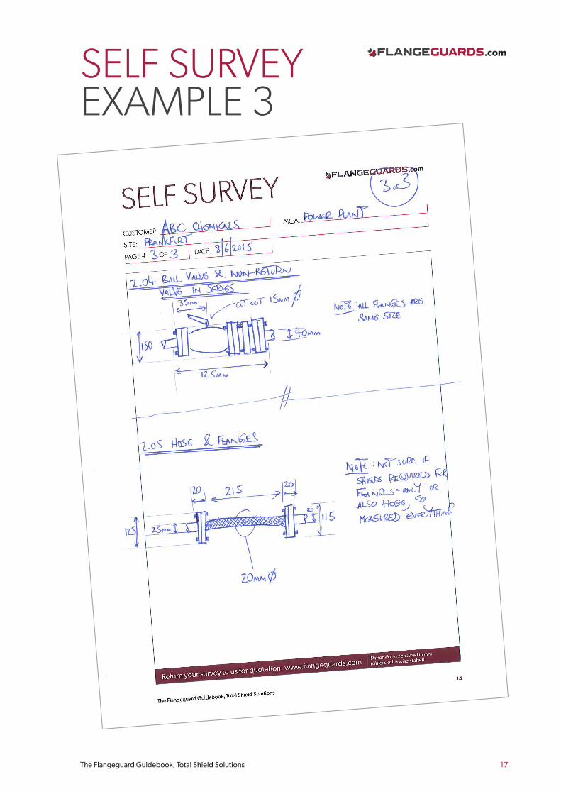
2. For non-standard pipe joints/fittings, make a basic drawing or take a photo (if site conditions allow) and add dimensions.
3. For installation purposes, note the area you are in within the plant/site and the process (sulphuric, caustic, fuel oil etc). You can even note ID/tag numbers for specific tanks, pumps, valves. We can also tag the safety shields individually, if required.
4. If in doubt, ask us. We have over twenty five years’ experience and are always happy to make recommendations and clarify specific dimensions required. We can also perform site surveys on your behalf, ask your local representative for details.
5. Have a tape measure and ideally a pair of callipers. These make outside diameter measurement simple, otherwise circumference can be measured.
APPENDIXi. SURVEY GUIDE .....................................................9
ii. SELF SURVEY FORM .......................................... 11
iii. SELF SURVEY EXAMPLES .................................15
iv. VALVE SHIELDS – QUICK REFERENCE.........18
v. FLANGE TABLES ................................................ 20

.com
The Flangeguard Guidebook, Total Shield Solutions 10
Here is a list of common applications;
FLANGESFor standard flange sizes, we simply need to know outside flange diameter, but also ideally the pipe size and width. You can either (1) physically measure these dimensions or (2) simply tell us the pipe size and flange rating:-
1
2
(for non-standard flange sizes, we prefer you to take manual measurement)
We can make shields for non-circular flanges such as SAE oval and square shapes. However, unless you advise us otherwise we will assume flanges are circular. Refer to the Joint-Types section of our website for further information.
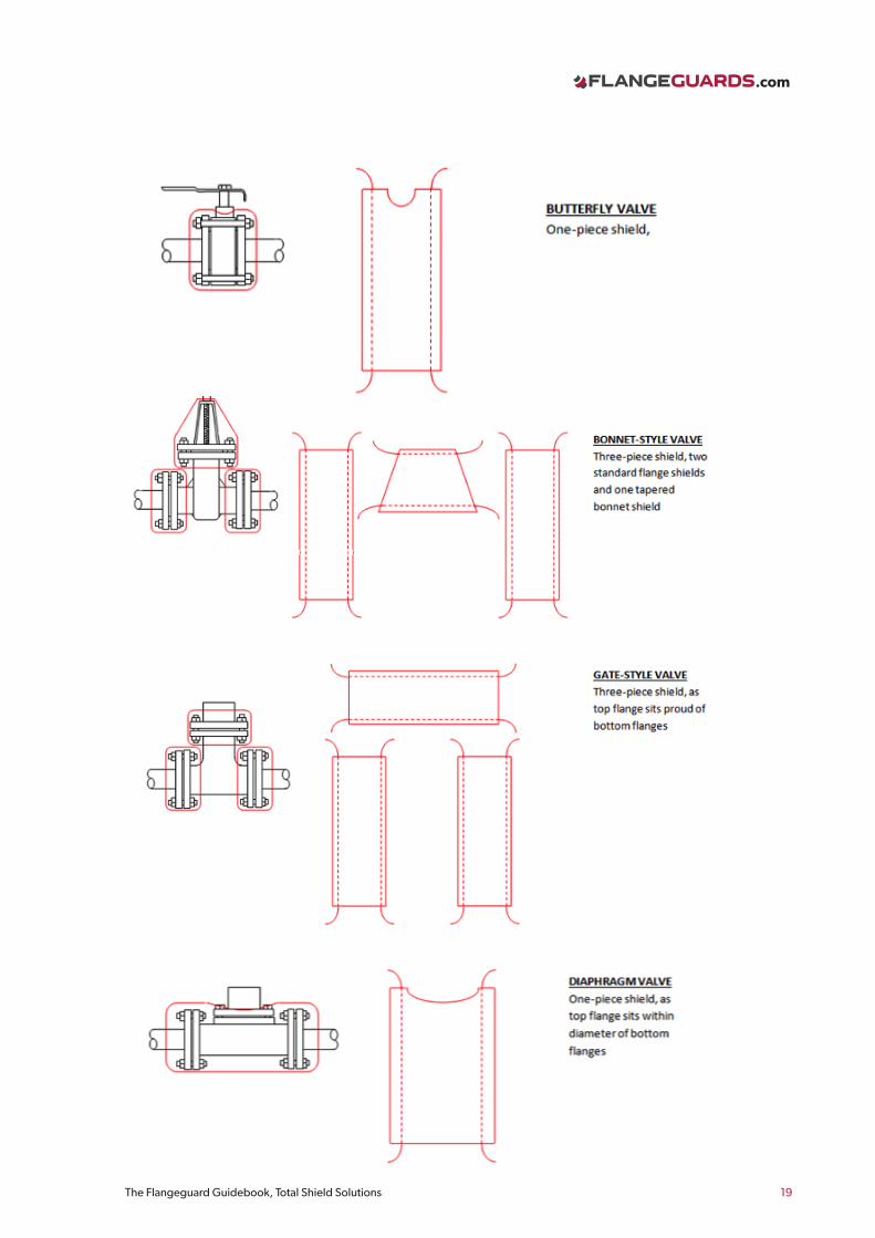
VALVESWe can make shields for virtually any valve configuration. Typical valve types include;
Ball, butterfly, swing-check, wafer-check, non-return, plug, bonnet, diaphragm
So for standard flanged Ball, Butterfly and Non-Return valves we simply need to know:-1. Valve Type2. Pipe Size3. Flange Class (or if screw connection)
Eg. Ball Valve, 50mm NB, PN25
Our shields will be made with cut-outs to accommodate valve handles and actuators. Unless you tell us otherwise, we will assume there’s a handle, centrally placed (apart from non-return valves, where generally there is no handle).
Some actuator structures are larger than others, so please provide as much information as possible if the valve is actuated, or if the handle is offset. See our valve shield quick-reference guide, Appendix V.
OTHER JOINTSFor anything else, measure all the dimensions that you think will be pertinent – bearing in mind that we need to make the shield big enough to wrap around the areas that need protection. See survey-samples for further details.
ITEMS THAT WE CAN AND HAVE SHIELDED BEFORE:-
• Expansion Joints / Bellows• Couplings, Unions, Hose Connections,
Elbows, Tees• Whole Pipe Sections and Hose Lengths• Heat Exchangers• Whole Filters and Filter Tops• Whole Pump Sets• Flanges; SAE, Oval, Square, Extra-Wide,
Non-Even• Sight Glasses• Flow Indicators and Meters
.com
The Flangeguard Guidebook, Total Shield Solutions 11
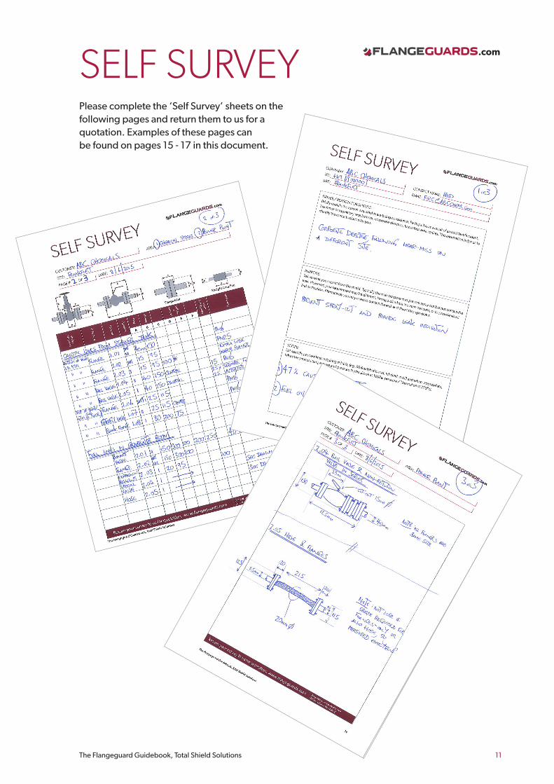
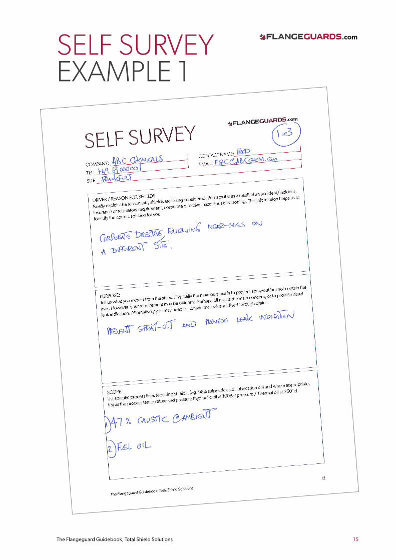
SELF SURVEYPlease complete the ‘Self Survey’ sheets on the following pages and return them to us for a quotation. Examples of these pages can be found on pages 15 - 17 in this document.

.com
The Flangeguard Guidebook, Total Shield Solutions 12
SELF SURVEYCOMPANY: CONTACT NAME:
TEL: EMAIL:
SITE:
DRIVER / REASON FOR SHIELDS Briefly explain the reason why shields are being considered. Perhaps it is as a result of an accident/incident, insurance or regulatory requirement, corporate directive, hazardous area zoning. This information helps us to identify the correct solution for you.
PURPOSE: Tell us what you expect from the shield. Typically the main purpose is to prevent spray-out but not contain the leak. However, your requirement may be different. Perhaps oil mist is the main concern, or to provide visual leak indication. Alternatively you may need to contain the leak and divert through drains.
SCOPE:List specific process lines requiring shields, (eg. 98% sulphuric acid, lubrication oil) and where appropriate, tell us the process temperature and pressure (hydraulic oil at 100Bar pressure / Thermal oil at 250°c).
.com
13The Flangeguard Guidebook, Total Shield Solutions
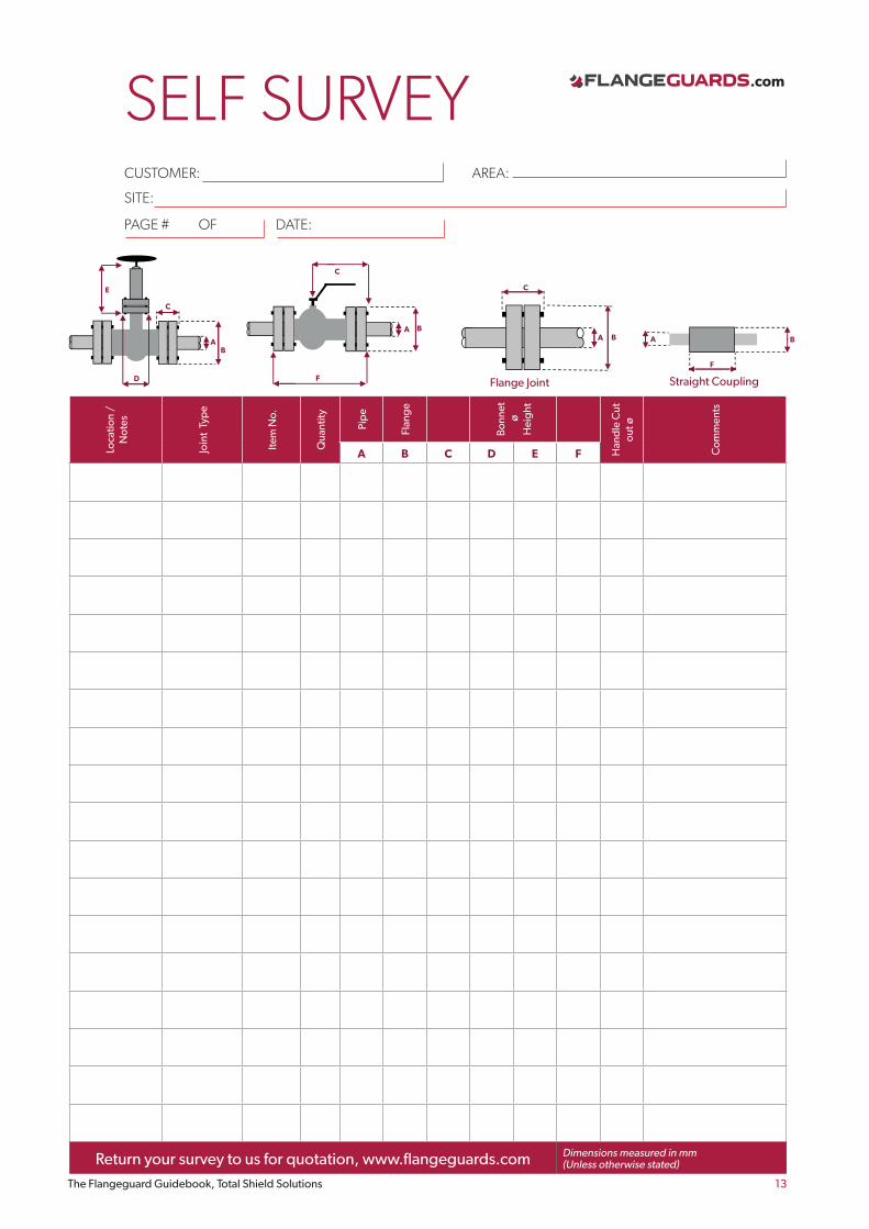
SELF SURVEYCUSTOMER: AREA:
SITE:
C
BA
Flange Joint
A
C
D
A
E
B
B
F
A
Straight Coupling
A
F
A
C
B
C
BA
Flange Joint
A
C
D
A
E
B
B
F
A
Straight Coupling
A
F
A
C
B
PAGE # OF DATE:
Loca
tion
/ N
otes
Join
t Ty
pe
Item
No.
Qua
ntity
Pip
e
Flan
ge
Bon
net
ø
Hei
ght
Han
dle
Cut
ou
t ø
Com
men
ts
A B C D E F
Return your survey to us for quotation, www.flangeguards.com Dimensions measured in mm(Unless otherwise stated)

.com
The Flangeguard Guidebook, Total Shield Solutions 14
SELF SURVEYCUSTOMER: AREA:
SITE:
PAGE # OF DATE:
Return your survey to us for quotation, www.flangeguards.com Dimensions measured in mm(Unless otherwise stated)
.com
The Flangeguard Guidebook, Total Shield Solutions 15
SELF SURVEYEXAMPLE 1

.com
The Flangeguard Guidebook, Total Shield Solutions 16
SELF SURVEYEXAMPLE2
.com
The Flangeguard Guidebook, Total Shield Solutions 17
SELF SURVEYEXAMPLE 3

.com
The Flangeguard Guidebook, Total Shield Solutions 18
VALVE SHIELDS - QUICK REFERENCE A wide variety of valve designs, sizes and configurations exist. We can tailor our shields to exactly fit any valve but common configurations are listed below, showing shield shape and fit. This information is useful during the survey, to identify the measurements required.
.com
The Flangeguard Guidebook, Total Shield Solutions 19
.com
The Flangeguard Guidebook, Total Shield Solutions 20
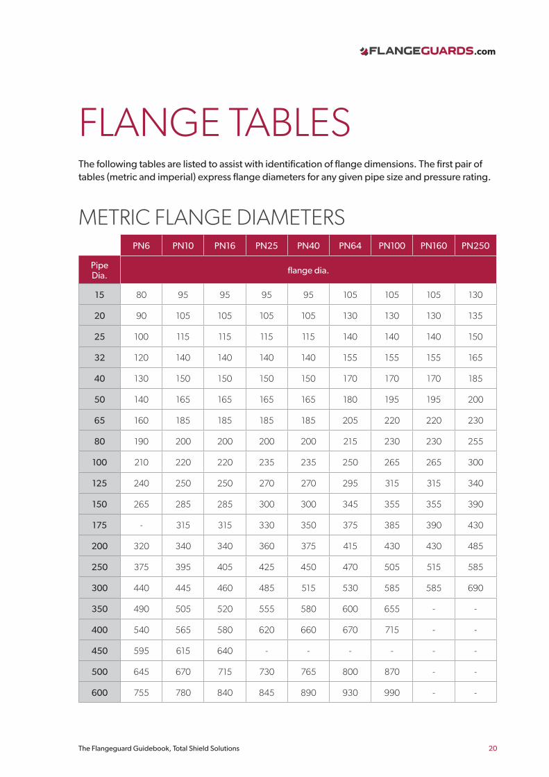
FLANGE TABLESThe following tables are listed to assist with identification of flange dimensions. The first pair of tables (metric and imperial) express flange diameters for any given pipe size and pressure rating.
PN6 PN10 PN16 PN25 PN40 PN64 PN100 PN160 PN250
Pipe Dia. flange dia.
15 80 95 95 95 95 105 105 105 130
20 90 105 105 105 105 130 130 130 135
25 100 115 115 115 115 140 140 140 150
32 120 140 140 140 140 155 155 155 165
40 130 150 150 150 150 170 170 170 185
50 140 165 165 165 165 180 195 195 200
65 160 185 185 185 185 205 220 220 230
80 190 200 200 200 200 215 230 230 255
100 210 220 220 235 235 250 265 265 300
125 240 250 250 270 270 295 315 315 340
150 265 285 285 300 300 345 355 355 390
175 - 315 315 330 350 375 385 390 430
200 320 340 340 360 375 415 430 430 485
250 375 395 405 425 450 470 505 515 585
300 440 445 460 485 515 530 585 585 690
350 490 505 520 555 580 600 655 - -
400 540 565 580 620 660 670 715 - -
450 595 615 640 - - - - - -
500 645 670 715 730 765 800 870 - -
600 755 780 840 845 890 930 990 - -
METRIC FLANGE DIAMETERS

.com
The Flangeguard Guidebook, Total Shield Solutions 21
FLANGE TABLES
150lb 300lb 600lb
Pipe Dia. flange dia.
1/2" 3 1/2" 3 3/4" 3 3/4"
3/4" 3 7/8" 4 5/8" 4 5/8"
1" 4 1/2" 4 7/8" 4 7/8"
1 1/4" 4 5/8" 5 1/4" 5 1/4"
1 1/2" 5" 6 1/8" 6 1/8"
2" 6" 6 1/2" 6 1/2"
2 1/2" 7" 7 1/2" 7 1/2"
3" 7 1/2" 8 1/4" 8 1/4"
4" 9" 10" 10 3/4"
5" 10" 11" 13"
6" 11" 12 1/2" 14"
8" 13 1/2" 15" 16 1/2"
10" 16" 17 1/2" 20"
12" 19" 20 1/2" 22"
14" 21" 23" 23 3/4"
16" 23 1/2" 25 1/2" 27"
18" 25" 28" 29 1/4"
20" 27 1/2" 30 1/2" 32"
24" 32" 36" 37"
IMPERIAL FLANGE DIAMETERS


