. INTRODUCTIONt is well known that an electromagnetic wave can beuided along the interface between a negative-epsilonaterial and a positive-epsilon material [1,2]. The guidedave has the maximum mode field localized at the inter-
ace between two materials, and it does not experienceny diffraction limit. Due to these two factors, suchaveguides have attracted a substantial amount of inter-st, specifically in the area of subwavelength light guidingnd sensing. In practice, some noble metals (e.g., gold andilver) have been used to take the role of negative-epsilonaterial at the visible and near-infrared wavelength
ange. The resulting waveguide is commonly referred tos a surface-plasmon-polariton (SPP) waveguide. Theame reflects the fact that the electron gas inside theetal is coupled to and in collective oscillation with the
utside photons. Various types of metal-based SPPaveguides have so far been realized, such as the metal
tripe waveguide [3,4], the V-shaped metal channel wave-uide [5,6], and the �-shaped metal wedge waveguide [7].
One special property of a SPP waveguide observed, asompared to all-dielectric waveguides, is that a mode cane confined in two dimensions (and propagating in thehird dimension) by a monoangular metal corner [5,7]. Onne hand, this property promises very simple waveguideonstructions. On the other hand, it indicates such SPPaveguides should have distinct geometric and chromaticodal properties as compared to conventional opticalaveguides. In fact, most waveguides, either all-dielectricr metallodielectric, are likely to include several cornersn their cross sections as a direct result of the current li-hography technology. Examples in reported literature in-lude the metal stripe waveguide [3,8–10], V-channelaveguide [5,11], U-channel waveguide [12], metal-slotaveguide [13–16], �-wedge waveguide [7], etc. Particu-
arly within the context of modes supported by the metaltripes, it has been observed that metal corners (in a 90°ngle) can guide plasmon polaritons on their own [9,17].or a complex metallodielectric waveguide, when theetal corners and the waveguiding metal-dielectric inter-
aces are in close proximity, the modal property of theverall waveguide can be very problematic to comprehendithout in-depth knowledge of a single-corner waveguide.
n [18], preliminary calculations by Moreno et al. havehown that all three metal corners (the channel bottomnd two side wedges) in a realistic V-channel waveguideend to guide light on their own, causing complex modaloupling and transitions as the wavelength is changed. As
result, an uncarefully designed V-channel waveguideay not confine light at the channel bottom. Reference
18], however, concentrated on one particular V-channelaveguide, and the effect of geometric variations is notiscussed. It is the objective of this paper to investigateroperties of modes guided by a general monoangularetal corner, be it either a channel (V shaped) or a wedge
� shaped). The cross sections of V-channel and �-wedgeaveguides are shown schematically in Figs. 1(a) and(c), respectively. The flat surface waveguide [Fig. 1(b)] isspecial case in our study, which has a corner angle of
80°. A monoangular metal-corner waveguide has twoong-enough sidewalls, so the guided mode is solely attrib-ted to this single corner, not influenced by any adjacentorners or curvature changes. As mentioned earlier,nowing the modal behavior of such metal-corneraveguides can help us to better understand more com-lex metallodielectric waveguides, which most often con-ist of metal corners. We refer to modes guided by theseD metal corners in general as corner plasmon polaritonsCPPs).
This paper is organized in the following manner. In
007 Optical Society of America
Sfgcgsorowtcvi
2ATnolmpmotatvofipascsnlwtfi
Fce
BOsmm[cncfipCcdrtmvwadc
aiiaccvtbc
CWmc
w=ttsi
DAgptpAfd
F�mpma
2334 J. Opt. Soc. Am. B/Vol. 24, No. 9 /September 2007 M. Yan and M. Qiu
ection 2, we mention a few considerations that are help-ul for understanding both the waveguides themselves ineneral and our later content. Such considerations in-lude the numerical method, the problem of field diver-ence at an infinitely sharp metal corner, optical con-tants of materials employed, and mode symmetry, amongthers. In Section 3, we study the effect of geometric pa-ameters, namely, the corner angle and the tip sharpness,n the performances of V-channel and �-wedgeaveguides. In Section 4, we study the chromatic proper-
ies of the corner waveguides. Modal behaviors of realisticorner waveguides at long operating wavelength are in-estigated in Section 5. A discussion and conclusion follown Section 6.
. GENERAL CONSIDERATIONS. Numerical Methodhe finite-element method (FEM) has been chosen as theumerical tool for deriving the guided CPP modes. Previ-us theoretical analysis of such waveguides was mainlyimited to the finite-difference time-domain (FDTD)
ethod [7,11,18]. The traditional FDTD method inter-rets material interfaces (where the mode field is at itsaximum for such waveguides) cruelly owing to its use of
rthogonal mesh. The FEM has the advantage of defininghe material interfaces accurately, straight or curved. Inddition, the FEM uses an adaptive mesh resolution. Forhese two reasons. The FEM is expected to achieve con-ergence faster than FDTD. The employed FEM is basedn the wave equation governing the transverse magneticeld. The Gauss law for magnetic field, � ·H=0, is ex-lictly imposed for eliminating spurious modes [19]. Welso take advantage of second-order shape function topeed up convergence. For most of the structures we areoncerned about in this paper, a triangle edge size asmall as 1.5 nm is used at the metal corner tip. The totalumber of unknowns is different from problem to prob-
em, but mostly within 100,000–400,000. For problemsith a large number of unknowns, most often the aniso-
ropic finite-element meshes are used [20]. A samplenite-element mesh of normal Delaunay type is shown in
ig. 1. (a)–(c) show diagrams of V-channel, 1D surface, and-wedge metal waveguides, respectively. The hatched region isetal, and the white region is dielectric material. (d) Geometric
arameters for a generalized metal-corner waveguide. (e) Sampleesh of a circular region with a 200 nm diameter. The corner has30° angle, and is rounded with an arc of 10 nm in radius.
ig. 1(e), in which the domain diameter is 200 nm and theorner tip arc has a radius of 10 nm. The meshes are gen-rated using the freely available Gmsh [21].
. Field Singularity at Sharp Metal Cornersur numerical study confirmed the tendency of a field
ingularity at an infinitely sharp metal corner. Electro-agnetic field singularity at the corner of a penetratableaterial wedge has long before been noticed and studied
22–24]. Such singularity even exists in a rectangular-ore all-dielectric waveguide [25]. However, as the domi-ant field portion in such all-dielectric waveguide is lo-ated in the homogeneous core region, the presence ofeld singularities at the core-cladding corners does notrevent numerical mode derivation from converging. InPP waveguides, this is, however, not true. Mode fieldontracts to the corner tip and its propagation constantiverges if a higher numerical resolution is used. For thiseason, all corners are rounded with an appropriate arc inhis study. In fact, we argue that localization of the guidedode in such surface waveguides is largely owing to the
ariation in local surface curvature. Given a certainavelength, smaller curvature tends to attract more lightnd gives rise to a larger propagation constant. We willemonstrate how sensitively the mode changes with theorner sharpness in Section 3.
The schematic CPP waveguide shown in Fig. 1(d) givesgeneral picture of metal-corner waveguides to be stud-
ed. Notice that s can be zero, in which case the corner tips a single arc [Fig. 1(e)]. It should be kept in mind thatctual corners fabricated in experiments may be far moreomplex than what have been shown in the figure. It isertainly not possible to exhaust all possible structuralariations. However, we believe the results presented inhis paper give a general idea how the corner waveguidesehave, even when the corners are at a slightly higheromplexity.
. Material Parametersithout loss of generality, we choose silver (Ag) as theetal and air as the dielectric material. The dielectric
onstant of Ag is described in the Drude model as
� = �� −��0 − ����p
2
�2 + i��, �1�
ith ��=4.017, �0=4.896, �p=1.419�1016 rad/s, and �1.117�1014 rad/s. This Drude model is fitted according
o the measured data from Palik’s handbook [26]. Noticehat in [26], there are two experimental datasets pre-ented at the near-infrared wavelength regime. We haven particular used the data from [33] as cited in that book.
. General Properties of Corner Modess shown in Figs. 1(a)–1(c) a monoangular CPP wave-uide has reflection symmetry about the vertical lineassing through its vertex. It is possible to make use ofhis symmetry to reduce the problem size by half, with aroper symmetry condition defined on the reflection axis.preliminary symmetry analysis shows that both a per-
ect electric conductor (PEC, or E�=0, dE� /dn=0,H /dn=0, and H =0) and a perfect magnetic conductor
� �
(mHfg�mt�2tdiihFawwmc(e[ctaSttca2ltscst
dnnacm
gwwsttcgnca�battbgWpta
mdfiasCnda
rfwtrettt
wadkw
Faar(Mwwm
M. Yan and M. Qiu Vol. 24, No. 9 /September 2007 /J. Opt. Soc. Am. B 2335
PMC, or H�=0, dH� /dn=0, dE� /dn=0, and E�=0) sym-etry conditions are allowed at the reflection axis [27].owever, after a numerous number of calculations using
ull structures, we concluded that the V-channel wave-uide only guides modes with a PEC symmetry, and the-wedge waveguide only guides modes with a PMC sym-etry. The transverse electric field and magnetic field of
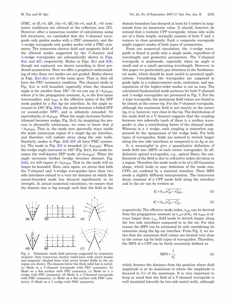
he allowed modes supported by the V-channel and-wedge waveguides are schematically shown in Figs.(a) and 2(f), respectively. Modes in Figs. 2(c) and 2(d),hough not captured, are shown according to their pre-icted symmetries. Here we offer a graphical understand-ng of why these two modes are not guided. Modes shownn Figs. 2(a)–2(c) are of the same gene. That is, they allave the PEC symmetry condition. The channel mode inig. 2(a) is well bounded, especially when the channelngle is far smaller than 180°. Or we can say ��k0nSPP,here � is the propagation constant, k0 is the free-spaceavenumber, and nSPP is the effective index of the SPPode guided by a flat Ag–air interface. As the angle in-
reases to 180° [Fig. 2(b)], the mode becomes a folded SPPor second-order SPP), and is infinitely extended. Orquivalently, �=k0nSPP. When the angle increases furtherchannel becomes wedge, Fig. 2(c)], by imagining the pro-ess is physically continuous, we come to know that �k0nSPP. That is, the mode now spectrally stays inside
he mode continuum region of a single Ag–air interface,nd therefore will radiate away along the side walls.imilarly, modes in Figs. 2(d)–2(f) all have PMC symme-ry. The mode in Fig. 2(f) is bounded ���k0nSPP�. Whenhe wedge angle increases to 180° [Fig. 2(e)], the mode be-omes the well-known SPP mode ��=k0nSPP�. When thengle increases further [wedge becomes channel, Fig.(d)], we will expect �k0nSPP. That is, the mode will noonger be bounded. Here, once again, we stress that bothhe V-channel and �-wedge waveguides have their twoide interfaces extend to a very far distance at which theorner-bounded mode has decayed significantly in itstrength. In actual numerical executions, we ensure thathe domain size is big enough such that the field at the
ig. 2. Schematic mode field patterns suggested by symmetrynalysis. Only transverse electric (solid lines with arrow heads)nd magnetic (dashed lines with arrow heads) fields in the airegion are shown. The domain below the thick solid line is metal.a) Mode in a V-channel waveguide with PEC symmetry. (b)
ode on a flat surface with PEC symmetry. (c) Mode on a �edge with PEC symmetry. (d) Mode in a V-channel waveguideith PMC symmetry. (e) Mode on a flat surface with PMC sym-etry. (f) Mode on a � wedge with PMC symmetry.
omain boundary has decayed at least by 3 orders in mag-itude from its maximum value. It should, however, beoticed that a realistic CPP waveguide, whose side wallsre of a finite length, normally consists of both V and �orners in close proximity. Such a composite waveguideight support modes of both types of symmetries.From our numerical simulation, the �-wedge wave-
uide is found to guide only a single mode, regardless ofavelength and geometric parameters. The V-channelaveguide is multimode, especially when its angle is
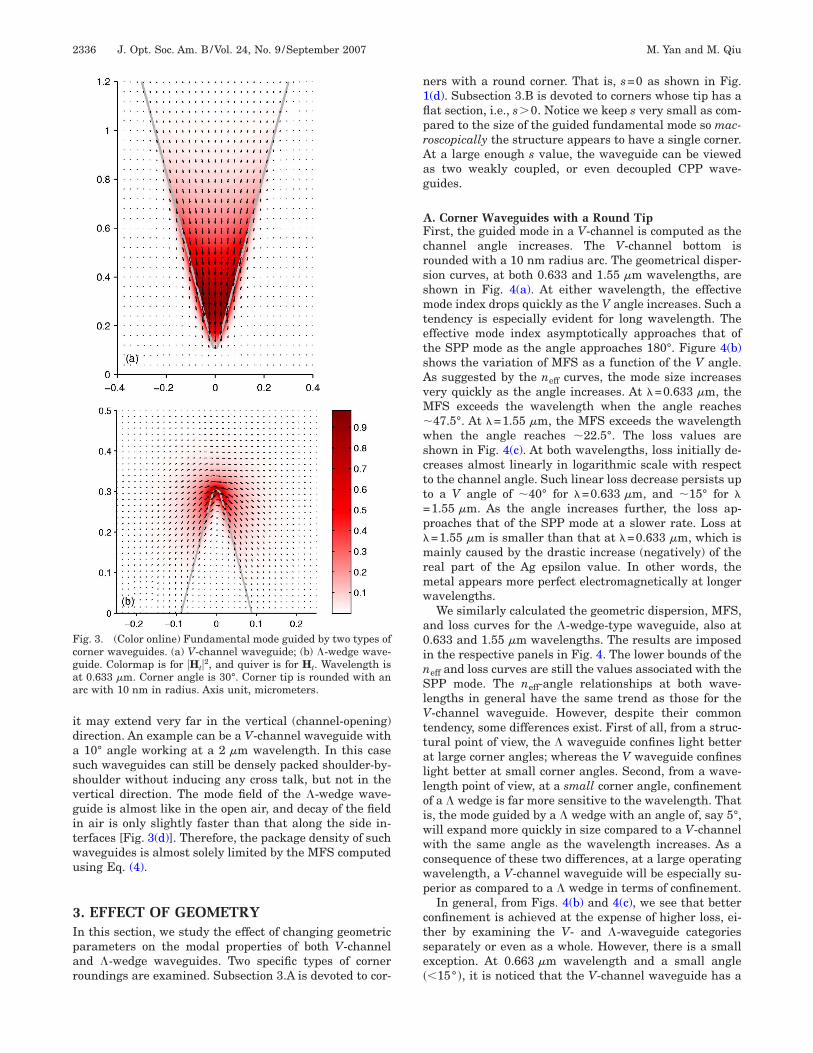
mall and at a small operating wavelength. However, inhis paper we particularly pay attention to the fundamen-al mode, which should be most useful in practical appli-ations. Considering the waveguides are supposed touide light in a submicrometer scale, excitation, and ma-ipulation of the higher-order modes is not as easy. Thealculated fundamental mode patterns for both V-channelnd �-wedge waveguides are presented in Fig. 3. For the-type waveguide, the maximum field values are found toe almost at the corner tip. For the V-channel waveguide,lthough the maximum field is not exactly at the cornerip, it is, however, very close to the tip. The distribution ofhe mode field in a V channel suggests that the couplingetween two sidewalls (each of them is a surface wave-uide) is also a contributing factor of the channel mode.hereas in a � wedge, such coupling is somewhat sup-
ressed by the opaqueness of the wedge body. For bothypes of waveguides, fields are noticed to stretch longerlong the two side interfaces as compared to in Ag or air.It is meaningful to give a quantitative definition ofode field size (MFS) of such corner waveguides. In all-
ielectric optical waveguides, e.g., optical fibers, the con-nement of the field is due to refractive index elevation inregion. Therefore the mode tends to be of a 2D Gaussian
hape, which leads to easy definition of the mode size.PPs are confined by a material interface. Their MFSeeds a slightly different interpretation. The transverseecay constant of a CPP mode field along the interfacend in the air can be written as
kts = k0�neff
2 − nSPP2 , �2�
kta = k0�neff
2 − nair2 , �3�
espectively. The effective mode index, neff, can be derivedrom the propagation constant as neff=� /k0. As nSPP is al-ays larger than nair, field tends to stretch longer along
he two side interfaces compared to in the air. For thiseason the MFS can be estimated by only considering itsxtension along the Ag–air interface. From Fig. 3, we no-ice that the maximum field values are located very closeo the corner tip for both types of waveguides. Therefore,he MFS of a CPP can be fairly accurately defined as
MFS =1
kts , �4�
hich denotes the distance from the position where fieldmplitude is at its maximum to where the amplitude isecayed to 1/e of the maximum. It is very important toeep in mind that the field of a V-channel waveguide isell insulated laterally by two side metal walls, although
idassvgitwu
3Ipar
n1flprAag
AFcrssmtetsAvM�wsctt=p�mrmw
a0inSlVttalloiwwcwp
ctse�
Fcgaa
2336 J. Opt. Soc. Am. B/Vol. 24, No. 9 /September 2007 M. Yan and M. Qiu
t may extend very far in the vertical (channel-opening)irection. An example can be a V-channel waveguide with10° angle working at a 2 m wavelength. In this case
uch waveguides can still be densely packed shoulder-by-houlder without inducing any cross talk, but not in theertical direction. The mode field of the �-wedge wave-uide is almost like in the open air, and decay of the fieldn air is only slightly faster than that along the side in-erfaces [Fig. 3(d)]. Therefore, the package density of suchaveguides is almost solely limited by the MFS computedsing Eq. (4).
. EFFECT OF GEOMETRYn this section, we study the effect of changing geometricarameters on the modal properties of both V-channelnd �-wedge waveguides. Two specific types of corneroundings are examined. Subsection 3.A is devoted to cor-
ig. 3. (Color online) Fundamental mode guided by two types oforner waveguides. (a) V-channel waveguide; (b) �-wedge wave-uide. Colormap is for �Ht�2, and quiver is for Ht. Wavelength ist 0.633 m. Corner angle is 30°. Corner tip is rounded with anrc with 10 nm in radius. Axis unit, micrometers.
ers with a round corner. That is, s=0 as shown in Fig.(d). Subsection 3.B is devoted to corners whose tip has aat section, i.e., s�0. Notice we keep s very small as com-ared to the size of the guided fundamental mode so mac-oscopically the structure appears to have a single corner.t a large enough s value, the waveguide can be vieweds two weakly coupled, or even decoupled CPP wave-uides.
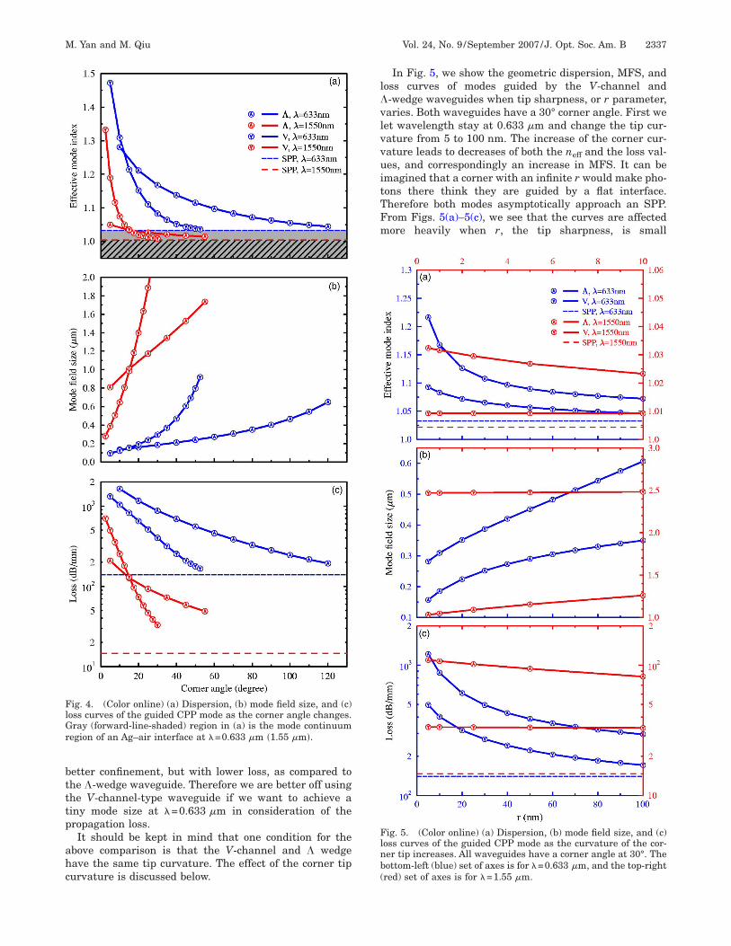
. Corner Waveguides with a Round Tipirst, the guided mode in a V-channel is computed as thehannel angle increases. The V-channel bottom isounded with a 10 nm radius arc. The geometrical disper-ion curves, at both 0.633 and 1.55 m wavelengths, arehown in Fig. 4(a). At either wavelength, the effectiveode index drops quickly as the V angle increases. Such a
endency is especially evident for long wavelength. Theffective mode index asymptotically approaches that ofhe SPP mode as the angle approaches 180°. Figure 4(b)hows the variation of MFS as a function of the V angle.s suggested by the neff curves, the mode size increasesery quickly as the angle increases. At �=0.633 m, theFS exceeds the wavelength when the angle reaches47.5°. At �=1.55 m, the MFS exceeds the wavelengthhen the angle reaches �22.5°. The loss values are
hown in Fig. 4(c). At both wavelengths, loss initially de-reases almost linearly in logarithmic scale with respecto the channel angle. Such linear loss decrease persists upo a V angle of �40° for �=0.633 m, and �15° for �1.55 m. As the angle increases further, the loss ap-roaches that of the SPP mode at a slower rate. Loss at=1.55 m is smaller than that at �=0.633 m, which isainly caused by the drastic increase (negatively) of the
eal part of the Ag epsilon value. In other words, theetal appears more perfect electromagnetically at longeravelengths.We similarly calculated the geometric dispersion, MFS,
nd loss curves for the �-wedge-type waveguide, also at.633 and 1.55 m wavelengths. The results are imposedn the respective panels in Fig. 4. The lower bounds of theeff and loss curves are still the values associated with thePP mode. The neff-angle relationships at both wave-
engths in general have the same trend as those for the-channel waveguide. However, despite their common
endency, some differences exist. First of all, from a struc-ural point of view, the � waveguide confines light bettert large corner angles; whereas the V waveguide confinesight better at small corner angles. Second, from a wave-ength point of view, at a small corner angle, confinementf a � wedge is far more sensitive to the wavelength. Thats, the mode guided by a � wedge with an angle of, say 5°,ill expand more quickly in size compared to a V-channelith the same angle as the wavelength increases. As a
onsequence of these two differences, at a large operatingavelength, a V-channel waveguide will be especially su-erior as compared to a � wedge in terms of confinement.In general, from Figs. 4(b) and 4(c), we see that better
onfinement is achieved at the expense of higher loss, ei-her by examining the V- and �-waveguide categorieseparately or even as a whole. However, there is a smallxception. At 0.663 m wavelength and a small angle15° �, it is noticed that the V-channel waveguide has a
btttp
ahc
l�vlvvuitTFm
FlGr
Flnb(
M. Yan and M. Qiu Vol. 24, No. 9 /September 2007 /J. Opt. Soc. Am. B 2337
etter confinement, but with lower loss, as compared tohe �-wedge waveguide. Therefore we are better off usinghe V-channel-type waveguide if we want to achieve ainy mode size at �=0.633 m in consideration of theropagation loss.It should be kept in mind that one condition for the
bove comparison is that the V-channel and � wedgeave the same tip curvature. The effect of the corner tipurvature is discussed below.
ig. 4. (Color online) (a) Dispersion, (b) mode field size, and (c)oss curves of the guided CPP mode as the corner angle changes.ray (forward-line-shaded) region in (a) is the mode continuum
egion of an Ag–air interface at �=0.633 m �1.55 m�.
In Fig. 5, we show the geometric dispersion, MFS, andoss curves of modes guided by the V-channel and-wedge waveguides when tip sharpness, or r parameter,aries. Both waveguides have a 30° corner angle. First weet wavelength stay at 0.633 m and change the tip cur-ature from 5 to 100 nm. The increase of the corner cur-ature leads to decreases of both the neff and the loss val-es, and correspondingly an increase in MFS. It can be
magined that a corner with an infinite r would make pho-ons there think they are guided by a flat interface.herefore both modes asymptotically approach an SPP.rom Figs. 5(a)–5(c), we see that the curves are affectedore heavily when r, the tip sharpness, is small
ig. 5. (Color online) (a) Dispersion, (b) mode field size, and (c)oss curves of the guided CPP mode as the curvature of the cor-er tip increases. All waveguides have a corner angle at 30°. Theottom-left (blue) set of axes is for �=0.633 m, and the top-rightred) set of axes is for �=1.55 m.
�wugfss5�r
tkwalcFptmo=Titcsigiwfi
BIw1atstefl“zsa�oo1
VAtnuNatv
tr
4ItApl
Ftwi
2338 J. Opt. Soc. Am. B/Vol. 24, No. 9 /September 2007 M. Yan and M. Qiu
30 nm�. This is quite different from all-dielectricaveguides, in which such a minor structural variationsually does not perturb a mode as much. This also sug-ests that irregularities, especially small ones, might af-ect performance of a plasmon polariton waveguide con-iderably. When r is large ��30 nm�, its variation inducesteady changes in all three curves, as shown in Figs.(a)–5(c). Among the two types of waveguides, the-wedge waveguide is observed to be more sentitive to thevalue, especially when r is very small.We then change the wavelength to 1.55 m, and vary
he tip curvature from 0.5 to 10 nm. We would like tonow if a very sharp tip would result in a small MFS evenhen the wavelength is large, and in turn we couldchieve high packaging density even at this relativelyong wavelength. We have consistently kept the numeri-al resolution at the corner tip at r /5, making use of theEM’s adaptive meshing advantage. The results are im-osed in the respective panels in Fig. 5. It is noticed thathe V-channel waveguide improves very little in confine-ent as the corner is getting sharper. Its MFS decreases
nly from 2.482 m at r=10 nm to 2.469 m at r0.5 nm. This confirms what has been noticed in [18].herefore, at increasing wavelength, the mode in a real-
stic V-channel waveguide will expand in size and inevi-ably cause modal couplings with the wedge corners. Inontrast, the mode guided by the �-wedge waveguidehows relatively more sensitive changes with a decreas-ng r value. In fact the modal change of the wedge wave-uide due to variation in r is almost comparable to thatnduced by variation of the corner angle (Fig. 4) at bothavelengths. Again, from Fig. 5, all improvement of con-nement is at the cost of higher propagation loss.
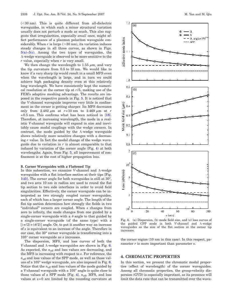
. Corner Waveguides with a Flattened Tipn this subsection, we examine V-channel and �-wedgeaveguides with a flat interface section at their tips [Fig.(d)]. The corner angle for both waveguides is still at 30°,nd two arcs 10 nm in radius are used to round the flatip section to two side interfaces in order to avoid fieldingularities. Effectively, the corner waveguide can be in-erpreted as two strongly coupled corner waveguides,ach of which has a larger corner angle. The length of theat tip section determines how strongly the fields in twoindividual” corners are coupled. When s changes fromero to infinity, the mode changes from one guided by aingle-corner waveguide with a � angle to that guided by
single-corner waveguide (of the same type) with a� /2�+ �� /2�� angle. Or, to put it another way an increasef s is equivalent to an increase of the angle. Therefore inur case, the 30° corner waveguide is transforming into a05° corner waveguide as s increases.The dispersion, MFS, and loss curves of both the
-channel and �-wedge waveguides are shown in Fig. 6.s expected, the neff and loss values are decreasing, and
he MFS is increasing with respect to s. For reference, theeff and loss values of the SPP mode, as well as those val-es of a 105° wedge waveguide, are also imposed in Fig. 6.otice that the neff and loss values of the mode guided byV-channel waveguide with a 105° angle is quite close to
hose values of a SPP mode [Fig. 4]. neff, MFS, and lossalues at s=0 are limited by the rounding curvature at
he corner region (10 nm in this case). In this respect, pa-ameter r is more important than parameter s.
. CHROMATIC PROPERTIESn this section, we present the chromatic modal proper-ies (effect of wavelength) of the corner waveguides.mong all chromatic properties, the group-velocity dis-ersion (GVD) is especially improtant, as its presence willimit the data rate that can be transmitted over the wave-
ig. 6. (a) Dispersion, (b) mode field size, and (c) loss curves ofhe guided CPP mode in both V-channel and �-wedgeaveguides as the size of the flat section at the corner tip
ncreases.
gmtotTGopst
ni
Baiiamwgr7wt
mTpwifwwcnpsbnotah�
Ctl(lt
awcc
F(t
M. Yan and M. Qiu Vol. 24, No. 9 /September 2007 /J. Opt. Soc. Am. B 2339
uide. Although the waveguides studied in this paper areeant to propagate light in the millimeter or submillime-
er range (e.g., for integrated optics applications), severeptical pulse broadening due to GVD can still deterioratehe optical signal and render the signal unintelligible.herefore, it is critical to understand quantitatively theVD property of such waveguides. Besides, the variationsf the neff and MFS values as a function of wavelengthrovide a hint on how a composite waveguide, which con-ists of both V and � corners in close proximity, behave ashe wavelength increases.
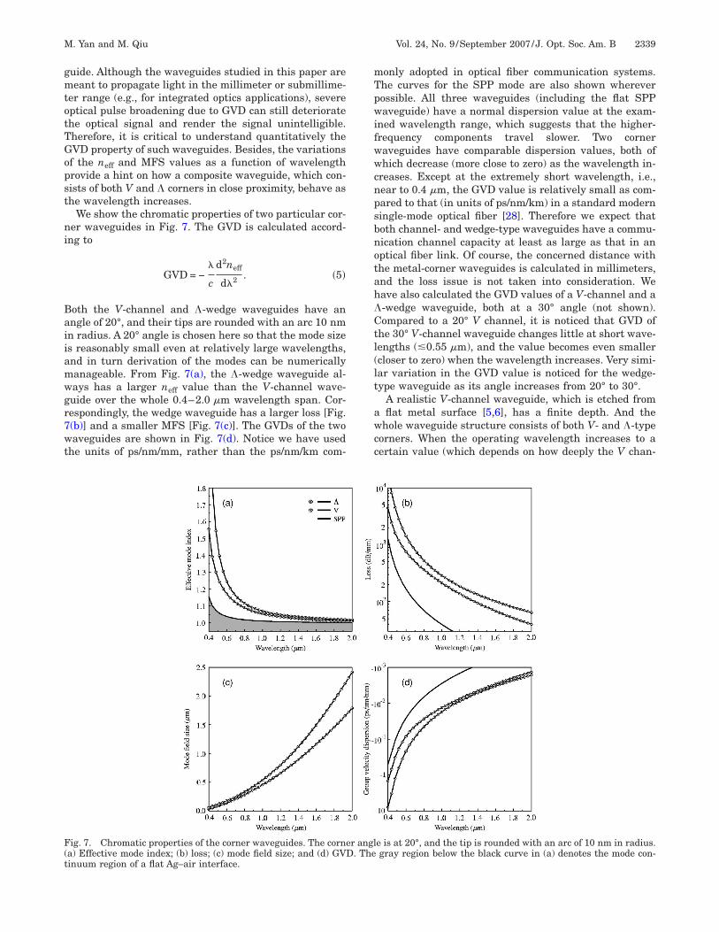
We show the chromatic properties of two particular cor-er waveguides in Fig. 7. The GVD is calculated accord-
ng to
GVD = −�
c
d2neff
d�2 . �5�
oth the V-channel and �-wedge waveguides have anngle of 20°, and their tips are rounded with an arc 10 nmn radius. A 20° angle is chosen here so that the mode sizes reasonably small even at relatively large wavelengths,nd in turn derivation of the modes can be numericallyanageable. From Fig. 7(a), the �-wedge waveguide al-ays has a larger neff value than the V-channel wave-uide over the whole 0.4–2.0 m wavelength span. Cor-espondingly, the wedge waveguide has a larger loss [Fig.(b)] and a smaller MFS [Fig. 7(c)]. The GVDs of the twoaveguides are shown in Fig. 7(d). Notice we have used
he units of ps/nm/mm, rather than the ps/nm/km com-
only adopted in optical fiber communication systems.he curves for the SPP mode are also shown whereverossible. All three waveguides (including the flat SPPaveguide) have a normal dispersion value at the exam-
ned wavelength range, which suggests that the higher-requency components travel slower. Two corneraveguides have comparable dispersion values, both ofhich decrease (more close to zero) as the wavelength in-
reases. Except at the extremely short wavelength, i.e.,ear to 0.4 m, the GVD value is relatively small as com-ared to that (in units of ps/nm/km) in a standard moderningle-mode optical fiber [28]. Therefore we expect thatoth channel- and wedge-type waveguides have a commu-ication channel capacity at least as large as that in anptical fiber link. Of course, the concerned distance withhe metal-corner waveguides is calculated in millimeters,nd the loss issue is not taken into consideration. Weave also calculated the GVD values of a V-channel and a-wedge waveguide, both at a 30° angle (not shown).ompared to a 20° V channel, it is noticed that GVD of
he 30° V-channel waveguide changes little at short wave-engths (�0.55 m), and the value becomes even smallercloser to zero) when the wavelength increases. Very simi-ar variation in the GVD value is noticed for the wedge-ype waveguide as its angle increases from 20° to 30°.
A realistic V-channel waveguide, which is etched fromflat metal surface [5,6], has a finite depth. And the
hole waveguide structure consists of both V- and �-typeorners. When the operating wavelength increases to aertain value (which depends on how deeply the V chan-
ig. 7. Chromatic properties of the corner waveguides. The corner angle is at 20°, and the tip is rounded with an arc of 10 nm in radius.a) Effective mode index; (b) loss; (c) mode field size; and (d) GVD. The gray region below the black curve in (a) denotes the mode con-inuum region of a flat Ag–air interface.
niTcctftcVqmodafa
5WIgbctsscma
waipsibaPas[smcgcvitPlebn
c�do
s�imtats
Fa
Ft=m
2340 J. Opt. Soc. Am. B/Vol. 24, No. 9 /September 2007 M. Yan and M. Qiu
el is etched), the mode guided by the channel bottom willnteract or couple with modes guided by two side wedges.his interaction is inevitable due to expansion of thehannel mode size. A quantitative knowledge of the “criti-al” wavelength can be obtained by examining the MFS ofhe mode in an infinitely deep V channel. For instance,rom Fig. 7(c), the MFS would be as large as 1 m whenhe wavelength is close to 1.4 m. Therefore strong modeoupling of the two types of metal corner is expected if the
channel has sidewalls 1 m long. Notice the conse-uence of increasing the wavelength is more than justodal mixing; the channel mode can be completely cut
ff. To explain such a cutoff is a bit more complicated. Weedicate Section 5 to this problem. In addition to the re-listic V-channel waveguide, we will also mention the ef-ect of increasing wavelength to the mode guided by a re-listic �-wedge waveguide.
. REALISTIC METAL-CORNERAVEGUIDES
n practice, a V channel can be realized by etching aroove from a flat metal film [6]. Similarly a � wedge cane sitting on a flat metal substrate. In other words, realorner waveguides have finite sidewalls. In addition,here will be some extra corners at the terminations of theidewalls. At a small-enough wavelength, the mode can beo well-confined that it may not be aware of neighboringorners. However, when the wavelength increases, theode will expand and interact with neighboring corners
nd even waveguiding structures further beyond.In fact, the mode guided by a V channel of finite height
ill experience a cutoff when the wavelength increases tocertain value. The explanation was partially mentioned
n [18]. Here we examine the phenomenon from the view-oint of supermodes, with special emphasis on the modeymmetry. In simple words, at a large wavelength, a real-stic V-channel waveguide is rather a superguide formedy three potential corner waveguides. Two types of modesre possible: one is of PEC symmetry, and the other is ofMC symmetry. All symmetries are about its reflectionxis. Notice that the V-channel bottom, if regarded as aingle waveguide, only guides modes with PEC symmetryFig. 2(a)]. That is, the channel bottom only contributes toupermodes with the PEC symmetry. Conversely, super-odes with PMC symmetry are antiresonant with the
hannel bottom for the symmetry reason, and its field isuided solely by two side wedges. Unfortunately for thehannel bottom, modes with the PMC symmetry are fa-ored at a large wavelength, since it can eventually evolvento the SPP mode [also of PMC symmetry, Fig. 2(e)] ashe wavelength increases. In contrast, supermodes withEC symmetry are likely to be cut off at large wave-
engths. And when the groove appears so small to the op-rating wavelength, the channel, or rather the channelottom, can be completely overlooked by the electromag-etic wave.We examined two types of modes guided by a realistic V
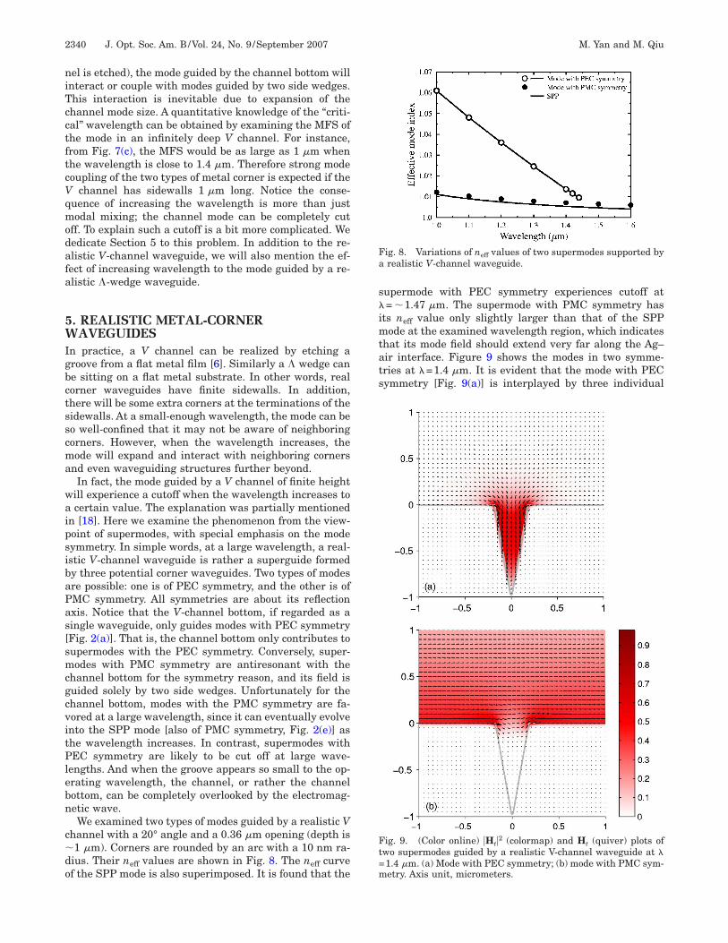
hannel with a 20° angle and a 0.36 m opening (depth is1 m). Corners are rounded by an arc with a 10 nm ra-
ius. Their neff values are shown in Fig. 8. The neff curvef the SPP mode is also superimposed. It is found that the
upermode with PEC symmetry experiences cutoff at= �1.47 m. The supermode with PMC symmetry has
ts neff value only slightly larger than that of the SPPode at the examined wavelength region, which indicates
hat its mode field should extend very far along the Ag–ir interface. Figure 9 shows the modes in two symme-ries at �=1.4 m. It is evident that the mode with PECymmetry [Fig. 9(a)] is interplayed by three individual
ig. 8. Variations of neff values of two supermodes supported byrealistic V-channel waveguide.
ig. 9. (Color online) �Ht�2 (colormap) and Ht (quiver) plots ofwo supermodes guided by a realistic V-channel waveguide at �1.4 m. (a) Mode with PEC symmetry; (b) mode with PMC sym-etry. Axis unit, micrometers.
ct
gValfsgtseig=tnhisi
6Ifi(cwomappVemasglfi�bwtwiw
ATStS
R
F�
Fmu
M. Yan and M. Qiu Vol. 24, No. 9 /September 2007 /J. Opt. Soc. Am. B 2341
orner waveguides, whereas the mode with PMC symme-ry [Fig. 9(b)] only takes efforts from two side wedges.
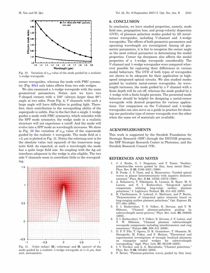
We also examined a �-wedge waveguide with the sameeometrical parameters. Notice now we have two-shaped corners with a 100° (always larger than 90°)ngle at two sides. From Fig. 4, V channels with such aarge angle will have difficulties in guiding light. There-ore, their contribution to the waveguiding ability of theuperguide is subtle. Due to the fact that a single � wedgeuides a mode with PMC symmetry, which coincides withhe SPP mode symmetry, the wedge mode in a realistictructure will not experience a cutoff. And the mode willvolve into a SPP mode as wavelength increases. We shown Fig. 10 the variation of neff value of the supermodeuided by the realistic � waveguide. The mode field at �2 m is plotted in Fig. 11. Notice the colormap now is for
he absolute value (not squared) of the transverse mag-etic field. As expected, at such a wavelength the modeas a quite large field size. Its coupling with the Ag–air
nterfaces adajacent to the wedge is also eligible. The twoide V channels seem to contribute little to the waveguid-ng.
ig. 10. Variation of neff value of the mode guided by a realistic-wedge waveguide.
ig. 11. (Color online) �Ht� (colormap) and Ht (quiver) of theode guided by a realistic �-wedge waveguide at �=2 m. Axis
nit, micrometers.
. CONCLUSIONn conclusion, we have studied properties, namely, modeeld size, propagation loss, and group-velocity dispersionGVD), of plasmon polariton modes guided by 2D metal-orner waveguides, including V-channel and �-wedgeaveguides. The effects of both geometric parameters andperating wavelength are investigated. Among all geo-etric parameters, it is fair to recognize the corner angle
s the most critical parameter in determining the modalroperties. Corner tip sharpness also affects the modalroperties of a �-wedge waveguide considerably. The-channel and �-wedge waveguides were compared wher-ver possible for capturing their differences in variousodal behaviors. The GVD of both types of waveguides
re shown to be adequate for their application in high-peed integrated optical circuits. We also studied modesuided by realistic metal-corner waveguides. As wave-ength increases, the mode guided by a V channel with anite depth will be cut off, whereas the mode guided by awedge with a finite height persists. The presented mode
ehavior should be helpful for designing a metal-corneraveguide with desired properties for various applica-
ions. Our comparison on the V-channel and �-wedgeaveguides can also serve as a guide in practice for choos-
ng one particular type of corner waveguide over the otherhen the same set of materials are available.
CKNOWLEDGMENTShis work is supported by the Swedish Foundation fortrategic Research (SSF) through the INGVAR program,he SSF Strategic Research Center in Photonics, and thewedish Research Council (VR).
EFERENCES AND NOTES1. J. J. Burke, G. I. Stegeman, and T. Tamir, “Surface-
polariton-like waves guided by thin, lossy metal films,”Phys. Rev. B 33, 5186–5201 (1986).
2. B. Prade, J. Y. Vinet, and A. Mysyrowicz, “Guided opticalwaves in planar heterostructures with negative dielectricconstant,” Phys. Rev. B 44, 13556–13572 (1991).
3. A. Boltasseva, T. Nikolajsen, K. Leosson, K. Kjaer, M. S.Larsen, and S. I. Bozhevolnyi, “Integrated opticalcomponents utilizing long-range surface plasmonpolaritons,” J. Lightwave Technol. 23, 413–422 (2005).
4. R. Charbonneau, N. Lahoud, G. Mattiussi, and P. Berini,“Demonstration of integrated optics elements based onlong-ranging surface plasmon polaritons,” Opt. Express 13,977–984 (2005).
5. S. I. Bozhevolnyi, V. S. Volkov, E. Devaux, and T. W.Ebbesen, “Channel plasmon-polariton guiding bysubwavelength metal grooves,” Phys. Rev. Lett. 95, 046802(2005).
6. S. I. Bozhevolnyi, V. S. Volkov, E. Devaux, J.-Y. Laluet, andT. W. Ebbesen, “Channel plasmon subwavelengthwaveguide components including interferometers and ringresonators,” Nature 440, 508–511 (2006).
7. D. F. P. Pile, T. Ogawa, D. K. Gramotnev, T. Okamoto, M.Haraguchi, M. Fukui, and S. Matsuo, “Theoretical andexperimental investigation of strongly localized plasmonson triangular metal wedges for subwavelengthwaveguiding,” Appl. Phys. Lett. 87, 061106 (2005).
8. I. V. Novikov and A. A. Maradudin, “Channel polaritons,”Phys. Rev. B 66, 035403 (2002).
9. P. Berini, “Plasmon-polariton waves guided by thin lossy
1
1
1
1
1
1
1
1
1
1
2
22
2
2
2
2
2
2
2342 J. Opt. Soc. Am. B/Vol. 24, No. 9 /September 2007 M. Yan and M. Qiu
metal films of finite width: bound modes of symmetricstructures,” Phys. Rev. B 61, 10484–10503 (2000).
0. P. Berini, “Plasmon-polariton waves guided by thin lossymetal films of finite width: bound modes of asymmetricstructures,” Phys. Rev. B 63, 125417 (2001).
1. D. K. Gramotnev and D. F. P. Pile, “Single-modesubwavelength waveguide with channel plasmon-polaritons in triangular grooves on a metal surface,” Appl.Phys. Lett. 85, 6323–6325 (2004).
2. S. I. Bozhevolnyi, “Effective-index modeling of channelplasmon polaritons,” Opt. Express 14, 9467–9476 (2006).
3. G. Veronis and S. Fan, “Guided subwavelength plasmonicmode supported by a slot in a thin metal film,” Opt. Lett.30, 3359–3361 (2005).
4. L. Liu, Z. Han, and S. He, “Novel surface plasmonwaveguide for high integration,” Opt. Express 13,6645–6650 (2005).
5. D. F. P. Pile, T. Ogawa, D. K. Gramotnev, Y. Matsuzaki, K.C. Vernon, K. Yamaguchi, T. OKamoto, M. Haraguchi, andM. Fukui, “Two-dimensionally localized modes of ananoscale gap plasmon waveguide,” Appl. Phys. Lett. 87,261114 (2005).
6. L. Chen, J. Shakya, and M. Lipson, “Subwavelengthconfinement in an integrated metal slot waveguide onsilicon,” Opt. Lett. 31, 2133–2135 (2006).
7. A. Degiron and D. R. Smith, “Numerical simulations oflong-range plasmons,” Opt. Express 14, 1611–1625 (2006).
8. E. Moreno, F. J. Garcia-Vidal, S. G. Rodrigo, L. Martin-Moreno, and S. I. Bozhevolnyi, “Channel plasmon-
polaritons: modal shape, dispersion, and losses,” Opt. Lett.31, 3447–3449 (2006).
9. H. E. Hernández-Figueroa, F. A. Fernández, Y. Lu, and J.B. Davies, “Vectorial finite element modelling of 2D leakywaveguides,” IEEE Trans. Magn. 31, 1710–1713 (1995).
0. M. Yan and M. Qiu, “Analysis of surface plasmon polaritonusing anisotropic finite elements,” IEEE Photon. Technol.Lett. (to be published).
1. Gmsh, http://www.geuz.org/gmsh/.2. J. Meixner, “The behavior of electromagnetic fields at
edges,” IEEE Trans. Antennas Propag. 20, 442–446 (1972).3. C. J. Bouwkamp, “A note on singularities occurring at