Guided Wave Testing (GWT) Use of guided wave testing for the detection and monitoring of corrosion under insulation Peter Philipp Independent GWT consultant Level 3 GUL Level 3 PCN GWT BINDT-ICorr. - 12/05/2013
Transcript
Guided Wave Testing (GWT)
Use of guided wave testing for the detection and monitoring of corrosion under insulation
Peter PhilippIndependent GWT consultant
Level 3 GUL Level 3 PCN GWT
BINDT-ICorr. - 12/05/2013
This presentation
•Brief history of GWT•How it works•How good is it at identifying CUI•Monitoring•New build considerations•Limitations•Procedures and training•Other GWT applications•Future developments
BINDT-ICorr. - 10/03/2013
GWT History
•Lamb waves identified in the 1930’s•Research projects in the 1990’s “Link and Thermie” programs •Development of “dispersion curves”•Required faster portable computers•First commercial equipment available 1999•Mid 2000’s Subsea, focussing, c-scan display, rail, permanently installed etc. •3 GWT systems developed Wavemaker (GUL) Teletest (Pi), MSS (SWRI)
BINDT-ICorr. - 10/03/2013
4
Guided Wave Testing Standards
• ASTM – 2011 • BSI – 9690 parts 1 & 2• TUV certification: GUL GWT procedure certified under
EN standard 14748• NACE TG 410 – 2012/13• ASME Article 18 – 2012/13Need for harmonization between the different standards.
Standards within integrated ‘system’ including legal requirements, codes and best industrial practices..;
Guided Ultrasonics Ltd. ‐ 12/05/2013
This presentation
•Brief history of GWT•How it works•How good is it at identifying CUI•Monitoring•New build considerations•Limitations•Procedures and training•Other GWT applications•Future developments
BINDT-ICorr. - 10/03/2013
Principle
Transducer
Metal structureMetal structure
Inspected AreaInspected Area
Transducer Ring
Inspected areaInspected area Inspected areaInspected area
Standard UT
Guided Waves
BINDT-ICorr. - 10/03/2013
Reflection from a Feature(such as corrosion)
When the guided wave hits a change in cross section (or impedance), it reflects back toward the transducer
Transducer
Structure
BINDT-ICorr. - 12/05/2013
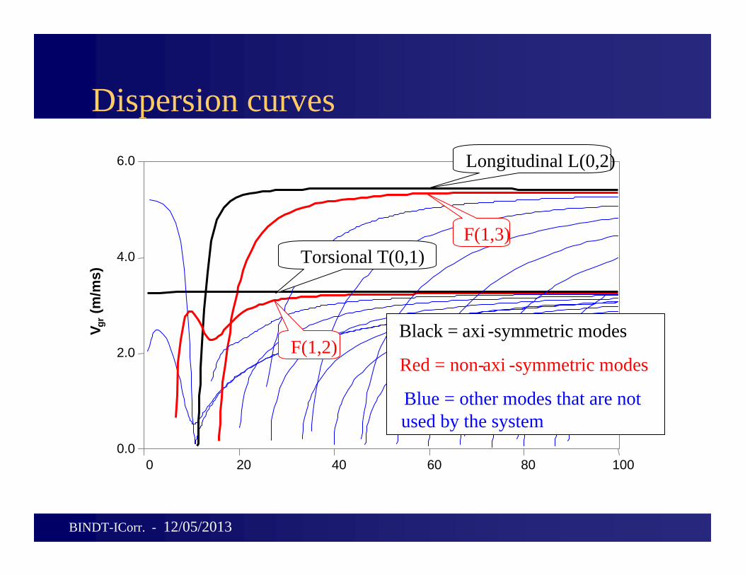
Dispersion curves
0 20 40 60 80 1000.0
2.0
4.0
6.0
V gr(m
/ms)
Longitudinal L(0,2)
F(1,3)
F(1,2)
Torsional T(0,1)
Black = axi -symmetric modes
Red = non-axi -symmetric modes
Blue = other modes that are notused by the system
BINDT-ICorr. - 12/05/2013
Position of Ring
Decay CurvesCorrosion is indicated
by large red component
Iconic representationof identified features
ForwardBackward
Series of Welds
BINDT-ICorr. - 10/03/2013
Guided Waves (Focusing) C-Scan display
BINDT-ICorr. - 12/05/2013
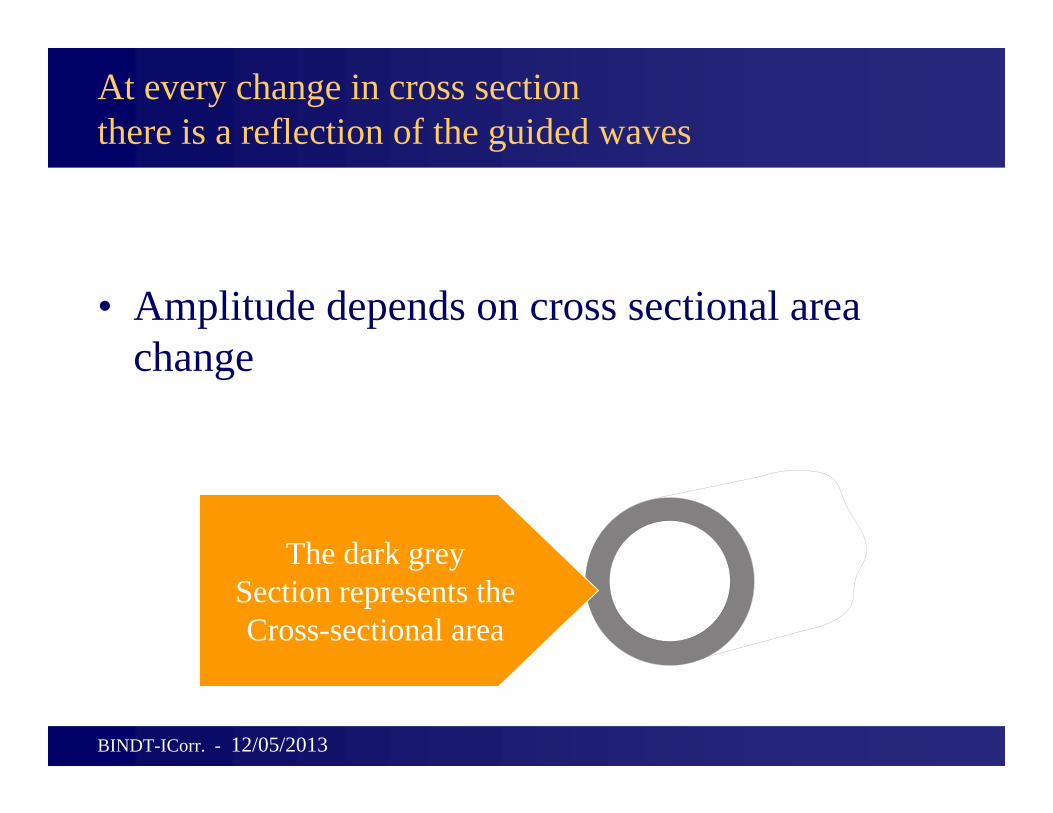
At every change in cross sectionthere is a reflection of the guided waves
• Amplitude depends on cross sectional area change
The dark greySection represents theCross-sectional area
BINDT-ICorr. - 12/05/2013
Distribution of Loss
• The percentage loss given by the ECL– could be concentrated in a narrow portion of the pipe
(e.g. a critical deep defect)– could be equally distributed around the circumference
(e.g. a shallow wall loss)
BINDT-ICorr. - 12/05/2013
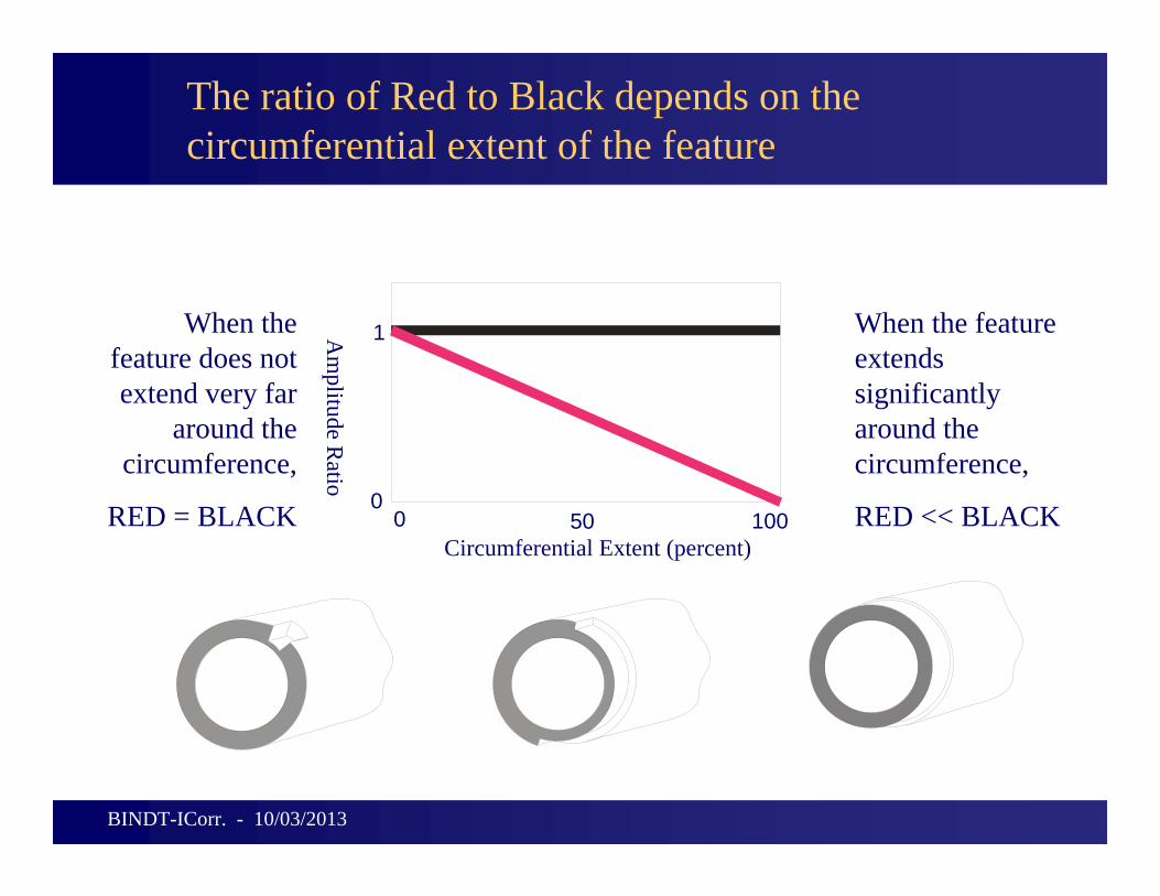
The ratio of Red to Black depends on the circumferential extent of the feature
Circumferential Extent (percent)
When the feature does not extend very far
around the circumference,
RED = BLACK
When the feature extends significantly around the circumference,
RED << BLACK00
1
50 100
Am
plitude Ratio
BINDT-ICorr. - 10/03/2013
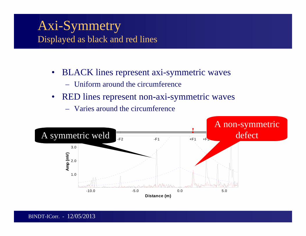
Axi-SymmetryDisplayed as black and red lines
• BLACK lines represent axi-symmetric waves– Uniform around the circumference
• RED lines represent non-axi-symmetric waves– Varies around the circumference
•Brief history of GWT•How it works•How good is it at identifying CUI•Monitoring•New build considerations•Limitations•Procedures and training•Other GWT applications•Future developments
BINDT-ICorr. - 10/03/2013
Why Guided Waves?
•100% volumetric coverage•Rapid screening•In Service inspection•Permanent record•Significantly reduced access costs Think of costs for:scaffolding, removing insulation, digging, operating underwater
BINDT-ICorr. - 10/03/2013
Rapid screening
• Very good at confirming clean pipe• Acts as filter: point out areas where
more attention is needed• Everyone knows about health
screening
BINDT-ICorr. - 12/05/2013
In-service inspection
• Temperature performances– from -40C to 180C– the extremes of this range will require modified procedures
• Product– low viscosity fluid does not affect torsional mode– frequency range enables good performances in case of
viscous fluid
• Pump noise, product flow– signal/noise can be improved using predefined software
procedures– In some cases (isolated) testing is not feasible
BINDT-ICorr. - 12/05/2013
Managing pipe inspection
Pipeline operators need to deal with kilometres of pipelines (each site)
How do operators manage the inspection now?
What capabilities are offered by Guided Waves?
BINDT-ICorr. - 12/05/2013
GWT and other complementary methods
• Prove up using other NDT methods (UT,RT, Leak detection, etc…)
• Use with RBI can be very powerful
BINDT-ICorr. - 12/05/2013
21
Touch point corrosion – 8” Sch 40
Guided Ultrasonics Ltd. ‐ 12/05/2013
-16d
B
-20 0 20 40 6012
9
6
3
12
Clo
ck
-20 0 20 40 600.0
0.2
0.4
0.6
0.8
1.0
1.2
Distance (ft)
Am
p (L
inea
r)
F
wel
ded
plat
e
Wel
d
Wel
d
Cat
1 C
orro
sion
Supp
ort
Wel
d
Cat
3 S
uppo
rt
-F1
Weld DAC 14%
Call DAC 4%
Touch point corrosion patch with pitting
22
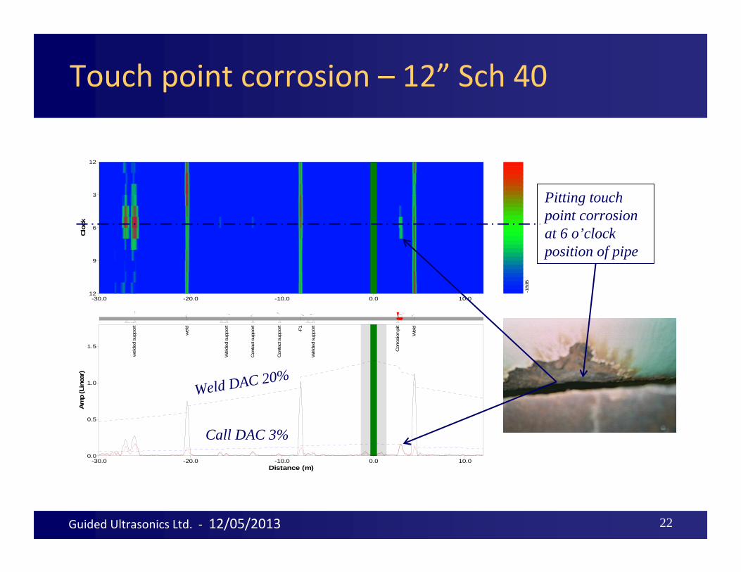
Touch point corrosion – 12” Sch 40
Guided Ultrasonics Ltd. ‐ 12/05/2013-1
8dB
-30.0 -20.0 -10.0 0.0 10.012
9
6
3
12
Clo
ck
-30.0 -20.0 -10.0 0.0 10.00.0
0.5
1.0
1.5
Distance (m)
Am
p (L
inea
r)
Wel
ded
supp
ort
-F1
Con
tact
sup
port
Con
tact
sup
port
Wel
ded
supp
ort
wel
d
wel
ded
supp
ort
Cor
rosi
on p
it
Wel
d
Pitting touch point corrosion at 6 o’clock position of pipe
Call DAC 3%
Weld DAC 20%
This presentation
•Brief history of GWT•How it works•How good is it at identifying CUI•Monitoring•New build considerations•Limitations•Procedures and training•Other GWT applications•Future developments
BINDT-ICorr. - 10/03/2013
100% Volumetric coverage
What is the probability of finding a defect using UT spot check compared to Guided Waves?
BINDT-ICorr. - 12/05/2013
100% Volumetric coverage
What is the probability of finding a defect using UT spot check compared to Guided Waves?
Example:10” pipe, 12m length with 2 simple supports
Per test:Standard UT = 0.027% area coverageGuided Wave ~ 100% area coverage
BINDT-ICorr. - 12/05/2013
Monitoring using GWT - Advantages
• Greatly improved sensitivity Normal testing ~ 1% to 5%
• Monitoring in the order of 10 times better as you are detecting changes
• Data from all tests can be stored for setting up same test parameters and also for comparison
• Can use removable or permanently installed transducers
• Data collection after base can be done by “data collectors”
BINDT-ICorr. - 10/03/2013
GW monitoring sensitivity
27Guided Ultrasonics Ltd. - 12/05/2013
2.5 3.0 3.5 4.00.0
1.0
2.0
3.0
Distance (m)
Amp (Linear)
+F1 +F2
baseline
0.5% CSC
0.75% CSC1% CSC
Simple visual estimate of change – slow and sometimes difficult method of interpreting GWT data differences
Riser GW monitoring results: The automatically processed comparisons
29Guided Ultrasonics Ltd. - 12/05/2013
The yellow trace is the reflection coefficient calculated from the 2010 reading using the calibration curves. The black trace is the difference between the 2010 and baseline readings.
Monitoring using GWT – Potential problems
The accuracy of comparing results must take into account the following:– Unique transducer identification– Ring position (for removable rings)– Calibration– Pipe temperature difference – Transducer coupling (permanent attachment)– Test parameters must be the same– Ideally the software should calculate the change
BINDT-ICorr. - 10/03/2013
This presentation
•Brief history of GWT•How it works•How good is it at identifying CUI•Monitoring•New build considerations•Limitations•Procedures and training•Other GWT applications•Future developments
BINDT-ICorr. - 10/03/2013
Using GWT – New build considerations
• Design for monitoring points especially when using permanently installed transducers
• For example sub sea and road crossings can be installed and take base line readings
• Design coatings etc to maximise range (avoid thick bitumastic coatings)
BINDT-ICorr. - 10/03/2013
This presentation
•Brief history of GWT•How it works•How good is it at identifying CUI•Monitoring•New build considerations•Limitations•Procedures and training•Other GWT applications•Future developments
BINDT-ICorr. - 10/03/2013
Dead zone
• Cannot test region of pipes close to the ring location
• Dead zone extending over 0.5m from ring (depends on test configuration)
BINDT-ICorr. - 12/05/2013
Range
• 5-150 meters in each direction depending on local conditions
• Factors affecting range– Geometry – General pipe conditions– Material inside pipe– Attenuative surface coating
BINDT-ICorr. - 12/05/2013
Difficult geometry
• Only test through one bend in each direction
• Defects at branches cannot be found reliably
• Flanges and Ts represent the end of the test
BINDT-ICorr. - 12/05/2013
Type of defect
• More difficult – Single isolated pit – Axial cracks– Small pits in welds
• Easier– A cluster of pits – Circumferential cracks– Large cracks in welds– CORROSION I/E -
EROSION
BINDT-ICorr. - 12/05/2013
This presentation
•Brief history of GWT•How it works•How good is it at identifying CUI•Monitoring•New build considerations•Limitations•Procedures and training•Other GWT applications•Future developments
BINDT-ICorr. - 10/03/2013
GWT Procedures
• Procedures need to be developed for:– Different applications– Permanent ring attachment and base test– Data collection from permanent rings– Comparison of monitoring data– Data management
BINDT-ICorr. - 10/03/2013
GWT operator training and certification
• The success of GWT is very operator dependant so good training/certification is crucial
• Some applications are more difficult• The main manufacturers have different
approach to training/certification• PCN agreed by all GWT equipment suppliers
available this year • CSWIP only available for Teletest
BINDT-ICorr. - 10/03/2013
Information management
• Managing information from NDT inspection is major issue.
• With Guided Waves each result contains in one file information on tens of meters of pipe.
• New development will enable asset integrity packages linking exact positioning of pipe features and defects (plotted on Google Earth for example)
BINDT-ICorr. - 12/05/2013
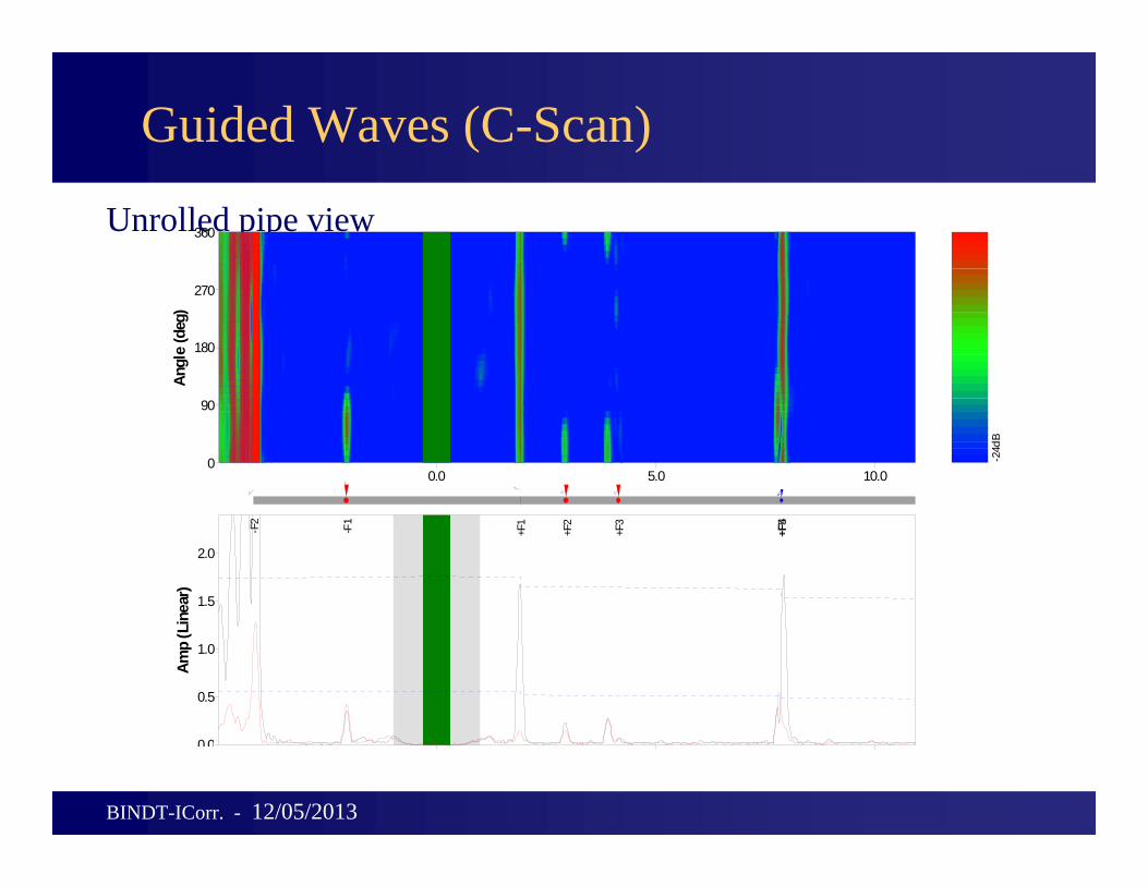
Guided Waves (C-Scan)
Unrolled pipe view
-24d
B
0.0 5.0 10.00
90
180
270
360
Angl
e (d
eg)
0 0
0.5
1.0
1.5
2.0
Amp
(Lin
ear)
+F5
+F4
+F3
+F2
+F1
-F1
-F2
BINDT-ICorr. - 12/05/2013
Interpretation - Frequency scanning
– Time saving when collecting data– Takes away responsibility from the inspector to
choose best frequencies on site– More information available which was not visible
before when collecting single frequencies– Extremely important in applications where the
feature response is frequency dependent– Helps distinguishing different features (e.g. defects
from supports)– POD
BINDT-ICorr. - 12/05/2013
Typical performance on bare straight pipe (20 years old in good conditions)
• 100 meters range on each side• Amplitude detection 1% Cross section • Concentration of defect (approximate)• Angle definition of defect +-22 degrees
Factors reducing range discussed below
BINDT-ICorr. - 12/05/2013
Applications
• Rapid, full coverage screening of pipes• Especially cost effective in difficult to access
– Almost no effect on the torsional mode– Affects the longitudinal mode when the pipe is fully filled
• Sludge– Heavy viscous deposits in the pipe attenuate the signal and reduce the
test range– Can be similar effect to bitumen wrapping
BINDT-ICorr. - 12/05/2013
This presentation
•Brief history of GWT•How it works•How good is it at identifying CUI•Monitoring•New build considerations•Limitations•Procedures and training•Other GWT applications•Future developments
BINDT-ICorr. - 10/03/2013
This presentation
•Brief history of GWT•How it works•How good is it at identifying CUI•Monitoring•New build considerations•Limitations•Procedures and training•Other GWT applications•Future developments
BINDT-ICorr. - 10/03/2013
Future developments
• Auto monitoring hardware and software• Asset integrity packages linking exact
positioning of pipe features and defects (plotted on Google Earth for example)