SOCIALIST REPUBLIC OF VIETNAM Ministry of Industry and Trade (MOIT) Guideline for Technical Regulation Volume 2 Design of Thermal Power Facilities Book 11/12 « Welding » Final Draft June 2013 Japan International Cooperation Agency Electric Power Development Co., Ltd. Shikoku Electric Power Co., Inc. West Japan Engineering Consultants, Inc. IL CR(2) 13-092
Transcript
SOCIALIST REPUBLIC OF VIETNAM Ministry of Industry and Trade (MOIT)
Guideline for Technical Regulation
Volume 2
Design of Thermal Power Facilities
Book 11/12
« Welding »
Final Draft
June 2013
Japan International Cooperation Agency
Electric Power Development Co., Ltd. Shikoku Electric Power Co., Inc.
West Japan Engineering Consultants, Inc.
IL
CR(2)
13-092
Table of Contents Chapter-1. Comparison between Technical Regulation and Technical Guideline of welding ............. 1
Chapter-2. Each Items of Guideline ................................................................................................... 1
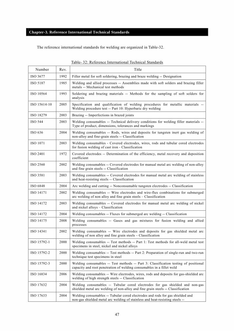
Chapter-3. Reference International Technical Standards .................................................................. 47
Chapter-4. Reference Japanese Technical Standards ........................................................................ 57
Chapter-6. Referenced Literature and Materials .............................................................................. 64
List of Tables Table- 1: Comparison between technical regulation and technical guideline of welding ............. 1 Table- 2: Classification pressure items in the power plant .......................................................... 9 Table- 3: Classification of welding method .............................................................................. 12 Table- 4: Check item for welding procedure ............................................................................ 13 Table- 5: Classification of base metal ...................................................................................... 14 Table- 6: Classification of the elements of the check items ...................................................... 15 Table- 7: Impact test temperature ............................................................................................. 16 Table- 8: Test method and criterion for welding procedure qualification test ........................... 17 Table- 9: Welding procedure specification (WPS) ................................................................... 18 Table- 10: Welding procedure qualification record (PQR) ....................................................... 19 Table- 11: Qualification testing matters for welder (welding method) ...................................... 21 Table- 12: Qualification testing matters for welder (test piece and welding position) ............... 22 Table- 13: Qualification testing matters for welder (test piece and welding position) ............... 23 Table- 14: Qualification testing matters for welder (welding rod) ............................................ 24 Table- 15: Qualification testing matters for welder (Filler metal (including weld insert) or core
wire) ................................................................................................................................ 24 Table- 16: Correspondence of welders’ skill classification ....................................................... 25 Table- 17: Correspondence of qualification classification between interpretations of ............... 26 Table- 18: Correspondence of qualification classification between interpretations of ............... 27 Table- 19: Correspondence of qualification classification between interpretations of ............... 28 Table- 20: Correspondence of qualification classification between interpretations of ............... 28 Table- 21: Approval testing of welder and criterion (other than aluminum or aluminum alloy) 30 Table- 22: Approval testing of welder and criterion (aluminum or aluminum alloy) ................. 32 Table- 23: Classification of test material, position and workable range .................................... 33 Table- 24: Classification of test material, position and workable range .................................... 35 Table- 25: Classification of welding rod .................................................................................. 36 Table- 26: Classification of welding metal ............................................................................... 37 Table- 27: Classification of filler metal or weld inserts ............................................................ 37
i
Table- 28: Temperature range for post weld heat treatment and retention time ......................... 38 Table- 29: Welder and welding operator performance qualification record .............................. 39 Table- 30: Comparison of various welders’ qualification system.............................................. 45 Table- 31: Comparison of various welders’ qualification system.............................................. 46 Table- 32: Reference International Technical Standards ........................................................... 47 Table- 33: Reference Japanese Technical Standards ................................................................. 57 Table- 34: Reference TCVN .................................................................................................... 62
List of Figures Fig- 1: Changes in main steam temperature ............................................................................... 2 Fig- 2: Changes in gas turbine inlet temperature ........................................................................ 3 Fig- 3: Conceptual schematic of welding object in the power plant .......................................... 10 Fig- 4: Test piece and specimen for plate ................................................................................. 40 Fig- 5: Test piece and specimen for pipe .................................................................................. 41 Fig- 6: Test piece and specimen for impact test ....................................................................... 42 Fig- 7: Installation of test piece for pipe (W-3-0r, W-3r, W-13r, W-14r and W-15r) ................ 43 Fig- 8: Welding position according to ASME .......................................................................... 44
List of Photos Photo- 1: Welding of LNG tank ................................................................................................. 3 Photo- 2: Welding of 9% Ni LNG tank ...................................................................................... 3 Photo- 3: Longitudinal welding of thick part ............................................................................. 4 Photo- 4: Submerge arc welding ................................................................................................ 4 Photo- 5: Welding of thick parts ................................................................................................ 4 Photo- 6: Welding of heavy wall piping ..................................................................................... 4 Photo- 7: Plasma automatic welding of LNG membrane ............................................................ 5 Photo- 8: Membrane .................................................................................................................. 5 Photo- 9: Welding of GT combustor (MHI) ................................................................................ 5 Photo- 10: Laser beam welding of GT swirler ............................................................................ 5 Photo- 11: Crusher hammers after repair .................................................................................... 6 Photo- 12: Hard-facing repair of screw conveyor ....................................................................... 6 Photo- 13: Hard-facing of roller laser welding ........................................................................... 6 Photo- 14: Hard-facing welding of roller ................................................................................... 6 Photo- 15: Repair welding of roller tire ..................................................................................... 7 Photo- 16: Hard-facing of roller table ........................................................................................ 7 Photo- 17: Overlay welding of incineration boiler ..................................................................... 7 Photo- 18: Overlay welding of boiler furnace wall ..................................................................... 7
ii
Photo- 19: Laser welding of gas turbine rotor (ALSTOM) ......................................................... 8 Photo- 20: Submerged arc welding of GT rotor .......................................................................... 8 Photo- 21: Divers welding subsea pipeline ................................................................................ 8 Photo- 22: Divers welding subsea pipeline ................................................................................ 8 Photo- 23: Titanium seal welding of tube ................................................................................... 9 Photo- 24: Aluminum welding of IPB ........................................................................................ 9
iii
List of Acronyms/Abbreviations
ABS American Bureau of Shipping
API American Petroleum Institute
AS/NZS Australia Standards / New Zealand Standards
ASME American Society of Mechanical Engineer
AWS American Welding Society
BPVC Boiler & Pressure Vessel Code
BS British Standard
CSA Canadian Standards Association
DIN Deutschen Industrie Normen
EN European Norm
FCAW Flux Cored Arc Welding
GMAW Metal Inert Gas Welding
ISO International Organization of Standardization
JGA Japan Gas Association
JIS Japanese Industrial Standard
JPI Japanese Petroleum Institute
JWES Japanese Welding Engineering Society
NK Nippon Kaiji Kyoukai
PD Published Document
PQR Procedure Qualification Record
SEW Süddeutsche Elektromotoren Werke
SMAW Shield Metal Arc Welding
YAG Yttrium Aluminum Garnet
WPS Welding Procedure Specification
iv
Chapter-1. Comparison between Technical Regulation and Technical Guideline of welding
The article number of this guideline is shown in the Table-1 contrasted technical regulation with
technical guideline for easy understanding.
Table- 1: Comparison between technical regulation and technical guideline of welding
Technical Regulation Technical Guideline
Article 228 General provision Article 228 General provision
-1. Necessity of welding management -1. Necessity for welding management
Article 229 Pressure parts Article 229 Pressure parts
-1. Classification by object -1. Classification by object
Article 230 Shape, etc. of welding parts Article 230 Shape, etc. of welding parts
-1. Sound welding -1. Sound welding
Chapter-2. Each Items of Guideline
Article 228.General provision Article 228-1. Necessity of welding management
1. The improvement of the performance of power generation facilities, reduction of manufacturing cost
and conservation cost rely on the technical innovation as shown in Fig-1 and Fig-2. In response to it,
the welding technology has been sophisticated and the importance of welding management and
requirement on the design has become larger.
2. When manufacturing the equipment of power plant, it is often performed in the factory where
environment has been well developed. On the other hand, those which must be assembled by welding
in the field are often constructed depending on the skill of worker in more severe environment in
terms of temperature, humidity, wind, foreign material, position and the like. Therefore, training and
confirmation of welding skill of welder or welding operator will affect the quality of the product.
3. Prior confirmation of the welding procedure specification and welding management during welding
work is important, though non-destructive test and pressure test after welding are also important,
since it is sensitive to the quality of welding depend on not only surface but also inner one.
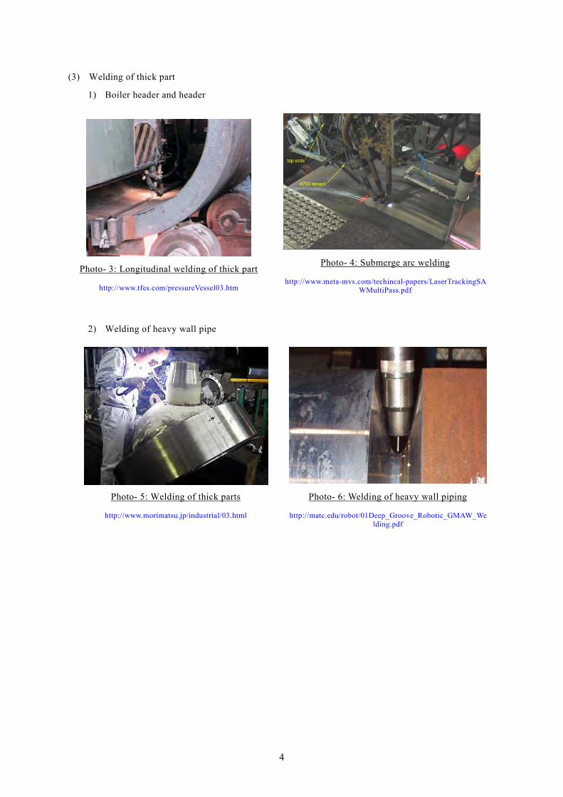
4. The development of welding technology is carried out followed by increasingly sophisticated and
expanding the scope of progress corresponding to the object, material, equipment to use, operation
condition and the like as shown in Photo-1 to Photo-24.
1
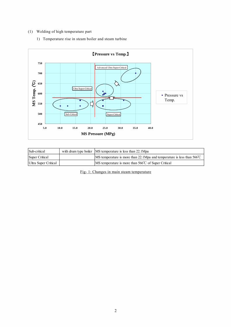
(1) Welding of high temperature part
1) Temperature rise in steam boiler and steam turbine
【Pressure vs Temp.】
450
500
550
600
650
700
750
5.0 10.0 15.0 20.0 25.0 30.0 35.0 40.0
MS Pressure (MPg)
MS
Tem
p. (℃
)
Pressure vsTemp.
Sub-Critical Super-Critical
Ultra Super-Critical
Advanced Ultra Super-Critical
Sub-critical with drum type boiler MS temperature is less than 22.1MpaSuper Critical MS temperature is more than 22.1Mpa and temperature is less than 566℃Ultra Super Critical MS temperature is more than 566℃ of Super Critical
Fig- 1: Changes in main steam temperature
2
2) Gas temperature rise at gas turbine inlet
【Design Efficiency vsTurbine Inlet Temp.】
40.0
45.0
50.0
55.0
60.0
65.0
1,000 1,200 1,400 1,600 1,800
Turbine Inlet Temp. (℃)
Des
ign
Effi
cien
cy (%
)
Design Efficiency vs Inlet Temp.
累乗 (Design Efficiency vs InletTemp.)
CC
ACC MACC
Super HT CC
CC 1100oC Combined CycleACC 1300oC Advanced combined cycle
1450oC1500oC1600oC
Super HT CC 1700oC Super high temperature combined cycle
1. Classification by operation pressure and temperature
35
30
25
20
15
10
5
-162 1000 1700400 500 600 7000 100 200 300
High alloy piping(MSP, Boiler SH)
Pres
sure
(MPa
)
High alloy piping(RSP, Boiler RH)
High alloy thin welding(GT brade, combustor)
Thick piping welding(Feedwater piping)
General welding(General piping)
Thin welding forlow temperature
(LNG tank)
Thick welding(Condenser, CWP)
Low pressure welding(Duct, tank, structure)
Low pressure welding(Low pressure piping)
Temperature (oC)
Fig- 3: Conceptual schematic of welding object in the power plant
Article 230. Shape, etc. of welding parts Article 230-1. Sound welding
1. General requirement
“Shall not have a discontinuous and peculiar shape” stipulated in design technical regulation
Article 230-1 must be pursuant as follows;
(1) “Those which have not a discontinuous and peculiar shape” stipulated in design technical
regulation Article 230-1-(1) means those which has not discontinuous and peculiar shape such as
sharp notch considering with welding groove when designing welding joint.
(2) “Those which is with no fear of cracks due to welding” stipulated in design technical regulation
Article 230-1-(2) means those which is confirmed by non-destructive examination and has no fear of
cracks due to welding. “to be no harmful lack of fusion or other defects to keep solidness of
welding part” means those which has proper design and shape of welding joint to prevent lack of
fusion and has no fear of cracks on the surface or inside of welding part.
(3) “Non-destructive examination” stipulated in design technical regulation Article 203-1-(2) means
the radiographic examination, ultrasonic examination, magnaflux examination, liquid penetrant
examination, visual inspection and the like.
(4) “Shall have the appropriate strength” stipulated in design technical regulation Article 230-1-(3)
means to confirm that has mechanical strength more than equal to the base metal by the welding
10
procedure test or pressure test and the like.
(5) “Which have been confirmed beforehand” stipulated in design technical regulation Article
230-1-(4) means those which the welding procedure, welding equipment and welder has been
confirmed as appropriate in advance. The welding procedure specification must be confirmed by
welding procedure examination or mechanical examination and the like.
2. Welding standards
There are many voluntary standards related to the welding procedure and welder qualification in each
country, in each field and each domain, for example, building structure, storage tank, pipeline,
pressure vessel and the like. The reliable and proven international standards have been observed,
though TCVN will be applied to the welding of power facility in Vietnam in preference. The
international standards related to welding such as ASME, API, BS, ISO, EN, AWS and the like are
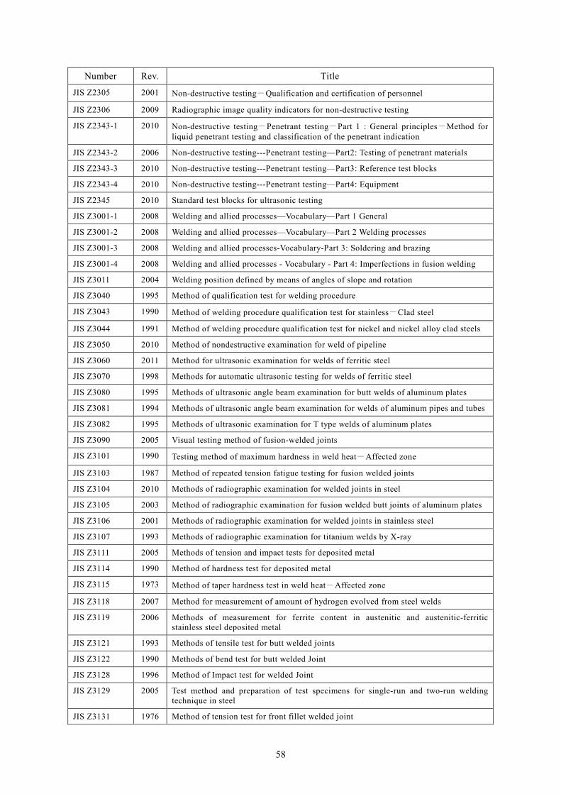
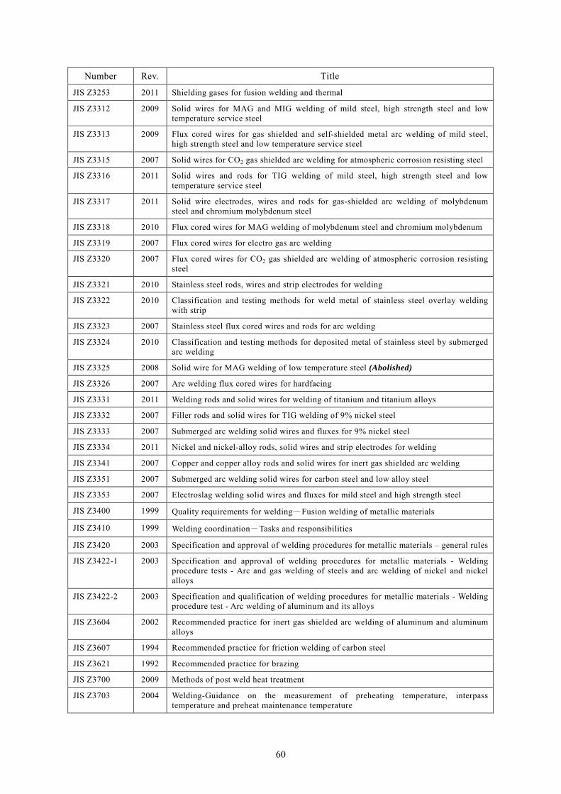
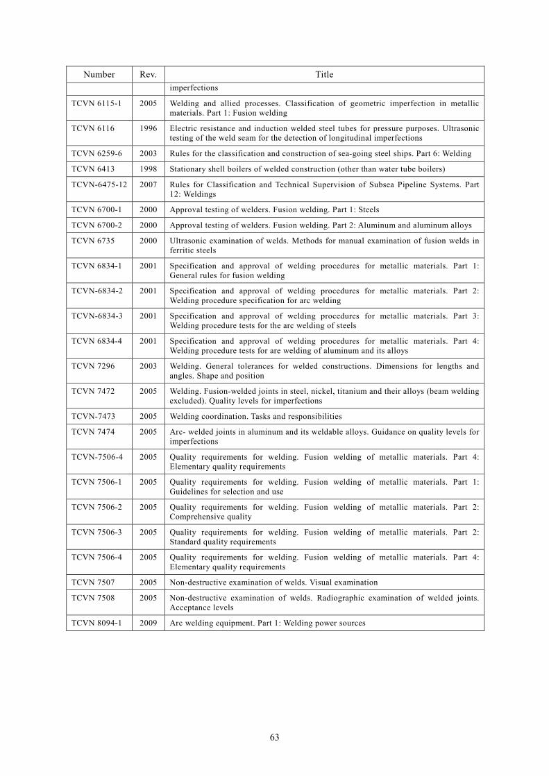
organized in Table-32, JIS standards related to welding are organized in Table-33, TCVN related to
welding are organized in Table-34.
In addition, the comparison between JIS standards and international standards related to welding are
organized in Table-30 and 31. Blank part is the part that needs to be verified on the perusal.
3. Welding procedure
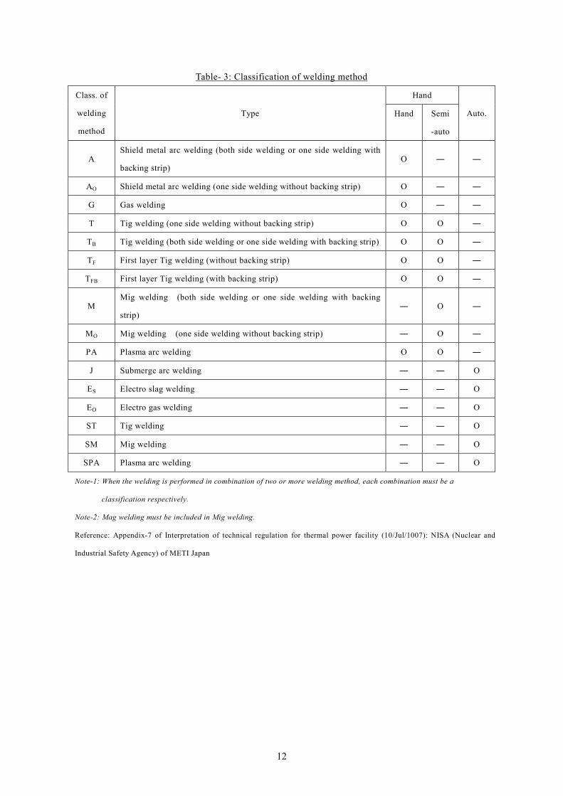
(1) Who performing welding work must carry out welding according to the appropriate welding method
depending on the welding method as shown in Table-3, items to be confirmed as shown in Table-4,
every element as shown in Table-6, by the testing method as shown in Table-8.
11
Table- 3: Classification of welding method
Class. of
welding
method
Type
Hand
Auto. Hand Semi
-auto
A Shield metal arc welding (both side welding or one side welding with
backing strip) O ― ―
AO Shield metal arc welding (one side welding without backing strip) O ― ―
G Gas welding O ― ―
T Tig welding (one side welding without backing strip) O O ―
TB Tig welding (both side welding or one side welding with backing strip) O O ―
TF First layer Tig welding (without backing strip) O O ―
TFB First layer Tig welding (with backing strip) O O ―
M Mig welding (both side welding or one side welding with backing
strip) ― O ―
MO Mig welding (one side welding without backing strip) ― O ―
PA Plasma arc welding O O ―
J Submerge arc welding ― ― O
ES Electro slag welding ― ― O
EO Electro gas welding ― ― O
ST Tig welding ― ― O
SM Mig welding ― ― O
SPA Plasma arc welding ― ― O
Note-1: When the welding is performed in combination of two or more welding method, each combination must be a
classification respectively.
Note-2: Mag welding must be included in Mig welding.
Reference: Appendix-7 of Interpretation of technical regulation for thermal power facility (10/Jul/1007): NISA (Nuclear and
Industrial Safety Agency) of METI Japan
12
Table- 4: Check item for welding procedure
Welding method
Items to be confirmed
Base metal Ο Ο Ο Ο Ο Ο Ο Ο Ο Ο Ο Ο Ο Ο Ο Ο
Welding rod Ο Ο Ο ― ― ― ― ― ― ― ― ― ― ― ― ―
Weld metal Ο※1 Ο※1 Ο※1 ― ― ― ― ― ― ― ― ― ― ― ― ―
Pre-heat Ο Ο Ο Ο Ο Ο Ο Ο Ο Ο Ο Ο Ο Ο Ο Ο
Post heat treatment Ο Ο Ο Ο Ο Ο Ο Ο Ο Ο Ο Ο Ο Ο Ο Ο
Sealed gas ― ― ― Ο Ο Ο Ο Ο Ο Ο ― ― Ο Ο Ο Ο
Gas shield from back ― ― ― Ο Ο Ο Ο Ο Ο Ο ― ― Ο Ο Ο Ο
Filler metal ― ― ― Ο Ο Ο Ο Ο Ο Ο ― ― ― Ο ― Ο
Weld insert ― ― ― Ο ― Ο ― ― ― Ο ― ― ― Ο ― Ο
Electrode ― ― ― Ο※2 Ο※2 Ο※2 Ο※2 Ο Ο Ο※2 Ο Ο Ο Ο Ο Ο
Flux ― ― ― ― ― ― ― ― ― ― Ο Ο ― ― ― ―
Core wire ― ― ― ― ― ― ― Ο Ο ― Ο Ο Ο ― Ο ―
Welding machine ― ― ― Ο※2 Ο※2 Ο※2 Ο※2 Ο Ο Ο※2 Ο Ο Ο Ο Ο Ο
Layer ― ― ― ― ― ― ― ― ― ― Ο Ο Ο Ο Ο Ο
Thickness of base metal Ο Ο Ο Ο Ο Ο Ο Ο Ο Ο Ο Ο Ο Ο Ο Ο
Nozzle ― ― ― ― ― ― ― ― ― ― ― Ο ― ― ― ―
Electric voltage & current ― ― ― ― ― ― ― ― ― ― ― Ο ― ― ― ―
Weaving ― ― ― ― ― ― ― ― ― ― ― Ο ― ― ― ―
Backing strip ― ― ― ― ― ― ― ― ― ― ― Ο Ο ― ― ―
Impact test Ο Ο Ο Ο Ο Ο Ο Ο Ο Ο Ο Ο Ο Ο Ο Ο
A Ao G T TB TF TFB M MO PA J ES EG ST SM SPA
Note:
(1) The symbol and type of welding method is shown in Table-3.
(2) “Ο” symbol shows the items to be confirmed.
(3) Shield gas must include replacement gas when the classification of orifice gas for plasma arc welding and the
classification of base metal are P-51 or P-52 as shown in Table-5 and performing welding in the closed vessel.
(4) The core wire must include the flux shield wire.
(5) “Remark-1”in the column “weld metal” must be confirmed in case of steel.
(6) “Remark-2”in the column “electrode” must be confirmed in case of semi-auto. Welding machine.
(7) A combination welding as shown in note of Table-3 must be confirmed related all items.
Reference: Appendix-8 of Interpretation of technical regulation for thermal power facility (10/Jul/1007): NISA (Nuclear and
Industrial Safety Agency) of METI Japan
13
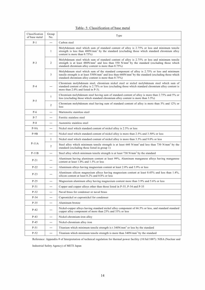
Table- 5: Classification of base metal
Classification of base metal
Group No. Type
P-1 ― Carbon steel
P-3
1 Molybdenum steel which sum of standard content of alloy is 2.75% or less and minimum tensile strength is less than 480N/mm2 by the standard (excluding those which standard chromium alloy content is more than 0.75%)
2 Molybdenum steel which sum of standard content of alloy is 2.75% or less and minimum tensile strength is at least 480N/mm2 and less than 550 N/mm2 by the standard (excluding those which standard chromium alloy content is more than 0.75%)
3 Molybdenum steel which sum of the standard component of alloy is 2.75% or less and minimum tensile strength is at least 550N/mm2 and less than 660N/mm2 by the standard (excluding those which standard chromium alloy content is more than 0.75%)
P-4 ― Chromium molybdenum steel, chromium nickel steel or nickel molybdenum steel which sum of standard content of alloy is 2.75% or less (excluding those which standard chromium alloy content is more than 2.0% and listed in P-3).
P-5 1 Chromium molybdenum steel having sum of standard content of alloy is more than 2.75% and 5% or
less (excluding those which standard chromium alloy content is more than 3.5%)
2 Chromium molybdenum steel having sum of standard content of alloy is more than 5% and 12% or less
P-6 ― Martensitic stainless steel
P-7 ― Ferritic stainless steel
P-8 ― Austenitic stainless steel
P-9A ― Nickel steel which standard content of nickel alloy is 2.5% or less
P-9B ― Nickel steel which standard content of nickel alloy is more than 2.5% and 3.50% or less
P-11A 1 Nickel steel which standard content of nickel alloy is more than 3.5% and 9.0% or less
2 Steel alloy which minimum tensile strength is at least 660 N/mm2 and less than 730 N/mm2 by the standard (excluding those listed in group 1)
P-11B ― Steel alloy which minimum tensile strength is at least 730 N/mm2 by the standard
P-21 ― Aluminum having aluminum content at least 99%, Aluminum manganese alloys having manganese content at least 1.0% and 1.5% or less
P-22 ― Aluminum alloys having magnesium content at least 2.0% and 3.9% or less
P-23 ― Aluminum silicon magnesium alloys having magnesium content at least 0.45% and less than 1.4%, silicon content at least 0.2% and 0.8% or less
P-25 ― Magnesium aluminum alloy having magnesium content more than 3.9% and 5.6% or less
P-31 ― Copper and copper alloys other than those listed in P-35, P-34 and P-35
P-32 ― Naval brass for condenser or naval brass
P-34 ― Cupronickel or cupronickel for condenser
P-35 ― Aluminum bronze
P-42 ― Nickel-copper alloys having standard nickel alloy component of 66.5% or less, and standard standard copper alloy component of more than 25% and 33% or less
P-43 ― Nickel-chromium-iron alloy
P-45 ― Nickel-chromium alloy iron
P-51 ― Titanium which minimum tensile strength is t 340N/mm2 or less by the standard
P-52 ― Titanium which minimum tensile strength is more than 340N/mm2 by the standard
Reference: Appendix-9 of Interpretation of technical regulation for thermal power facility (10/Jul/1007): NISA (Nuclear and
Industrial Safety Agency) of METI Japan
14
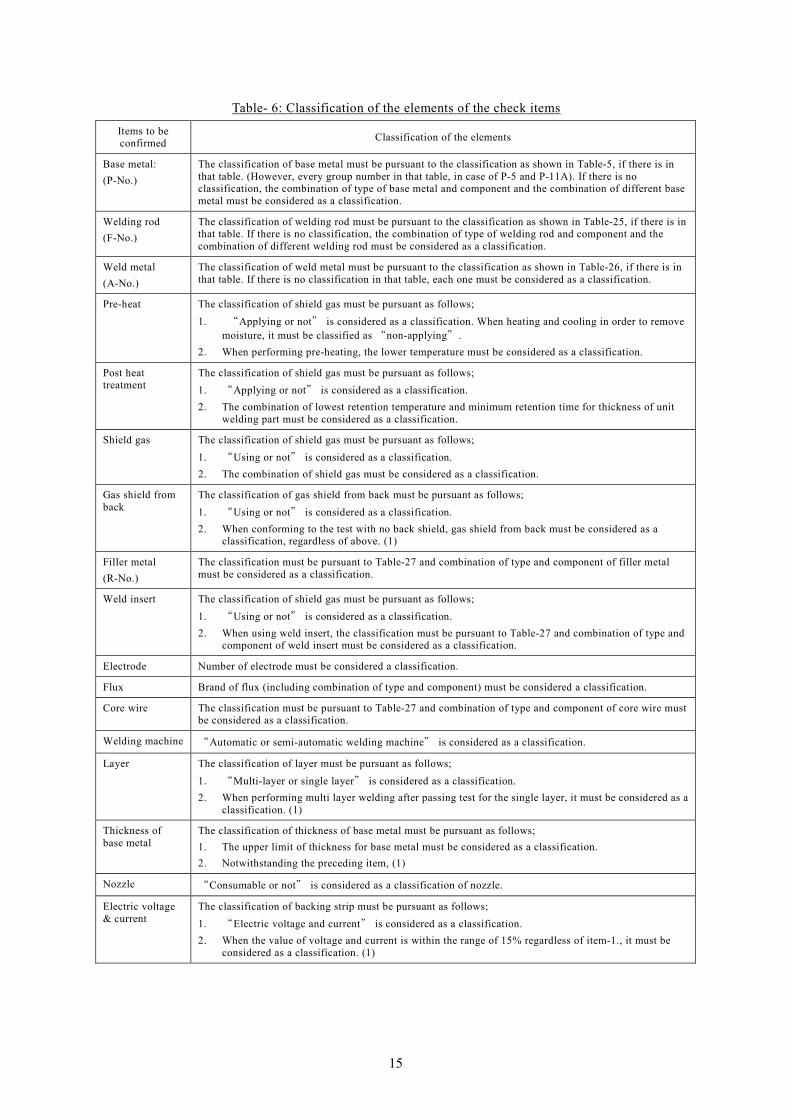
Table- 6: Classification of the elements of the check items
Items to be confirmed Classification of the elements
Base metal: (P-No.)
The classification of base metal must be pursuant to the classification as shown in Table-5, if there is in that table. (However, every group number in that table, in case of P-5 and P-11A). If there is no classification, the combination of type of base metal and component and the combination of different base metal must be considered as a classification.
Welding rod (F-No.)
The classification of welding rod must be pursuant to the classification as shown in Table-25, if there is in that table. If there is no classification, the combination of type of welding rod and component and the combination of different welding rod must be considered as a classification.
Weld metal (A-No.)
The classification of weld metal must be pursuant to the classification as shown in Table-26, if there is in that table. If there is no classification in that table, each one must be considered as a classification.
Pre-heat The classification of shield gas must be pursuant as follows; 1. “Applying or not” is considered as a classification. When heating and cooling in order to remove
moisture, it must be classified as “non-applying”. 2. When performing pre-heating, the lower temperature must be considered as a classification.
Post heat treatment
The classification of shield gas must be pursuant as follows; 1. “Applying or not” is considered as a classification. 2. The combination of lowest retention temperature and minimum retention time for thickness of unit
welding part must be considered as a classification.
Shield gas The classification of shield gas must be pursuant as follows; 1. “Using or not” is considered as a classification. 2. The combination of shield gas must be considered as a classification.
Gas shield from back
The classification of gas shield from back must be pursuant as follows; 1. “Using or not” is considered as a classification. 2. When conforming to the test with no back shield, gas shield from back must be considered as a
classification, regardless of above. (1)
Filler metal (R-No.)
The classification must be pursuant to Table-27 and combination of type and component of filler metal must be considered as a classification.
Weld insert The classification of shield gas must be pursuant as follows; 1. “Using or not” is considered as a classification. 2. When using weld insert, the classification must be pursuant to Table-27 and combination of type and
component of weld insert must be considered as a classification.
Electrode Number of electrode must be considered a classification.
Flux Brand of flux (including combination of type and component) must be considered a classification.
Core wire The classification must be pursuant to Table-27 and combination of type and component of core wire must be considered as a classification.
Welding machine “Automatic or semi-automatic welding machine” is considered as a classification.
Layer The classification of layer must be pursuant as follows; 1. “Multi-layer or single layer” is considered as a classification. 2. When performing multi layer welding after passing test for the single layer, it must be considered as a
classification. (1)
Thickness of base metal
The classification of thickness of base metal must be pursuant as follows; 1. The upper limit of thickness for base metal must be considered as a classification. 2. Notwithstanding the preceding item, (1)
Nozzle “Consumable or not” is considered as a classification of nozzle.
Electric voltage & current
The classification of backing strip must be pursuant as follows; 1. “Electric voltage and current” is considered as a classification. 2. When the value of voltage and current is within the range of 15% regardless of item-1., it must be
considered as a classification. (1)
15
Items to be confirmed Classification of the elements
Weaving The classification of backing strip must be pursuant as follows; 1. “Weaving or not” is considered as a classification.
2. “Width of weaving, frequency and stop time is considered as a classification when weaving in above case.
Backing strip The classification of backing strip must be pursuant as follows; 1. “Using or not” is considered as a classification.
2. “Non-ferrous or non-melting” is considered as a classification when using backing strip in above case.
Impact test If impact test is required, the lower temperature limit of impact test must be one classification.
Note: (1) It must be the classification of welding.
Reference: Appendix-10 of Interpretation of technical regulation for thermal power facility (10/Jul/1007): NISA (Nuclear
and Industrial Safety Agency) of METI Japan
(2) The welding and equipment as shown in Table-7 must be performed according to the welding
procedure that conforms to the impact testing.
Table- 7: Impact test temperature
Classification of equipment Classification of welding part Impact test temperature
Liquefied gas facility Longitudinal joint and circumferential joint Minimum operating temperature
Note: The following classification of welding part of the liquefied gas facility must be excluded.
1) Welding part with thickness less than 4.4mm.
2) Welding part with minimum operation temperature more than 30oC.
3) Following welding part other than 1) or 2).
a. Classification of base metal is P-8 (limited to those contain carbon less than 0.10%) or heat affected zone of
no-ferrous metal.
b. Welding part welded by austenic stainless steel, nickel chromium iron alloy steel or no-ferrous metal.
Reference: Appendix-12 of Interpretation of technical regulation for thermal power facility (10/Jul/1007): NISA (Nuclear
and Industrial Safety Agency) of METI Japan
(3) Criterion
1) When performing the test for welding procedure performance specification (WPS), it must
conform to the criterion as stipulated in Table-8.
2) When performing the impact test as prescribed in preceding paragraph, it must conform to the
criterion as stipulated in Table-8.
16
Table- 8: Test method and criterion for welding procedure qualification test
Testing method Criterion
1. Thickness of test piece must be as follow; (1) The value from 1/2 of upper limit value to upper limit value of the
thickness of base metal classified in the elements of check item (hereinafter referred “thickness of base metal” except in case of (2) to (4).
(2) The following cases, the value of the upper limit of thickness of the base metal; 1) When the outside diameter is 140mm or less and the upper limit of
thickness of base metal is more than 19mm, if the test piece to check is piping.
2) 32mm in P-1, 13mm in P-3, if the classification of base metal as shown in Table-5 is P-1 and P-3 and the lower limit of pr-heating temperature is 100oC.
3) The classification of base metal as shown in Table-5 is P-11A-1, P-11A-2 and P-11B.
4) When performing one side and one layer welding, in case of gas welding, Tig welding, plasma arc welding and semi-auto. Welding or automatic welding.
5) When welding on both sides as to make more servings on each side (limited to in case that thickness of base metal is more than 50mm).
(3) Value from 0.9 times of upper limit of thickness of base metal to upper limit, in case of electro-slug welding or electro-gas welding.
(4) Greater than equal to the thickness which can be collected specimen for v-notch test as stipulated in JIS Z2202-1998 “impact test specimen of metal material” other than from (1) to (3), in case performing impact test.
2. The method to install test piece as follow. However, if it is not proper when using special automatic welding machine, it must be the actual position.
(1) Downward, if the test piece is a plate. (2) Horizontal mounting or horizontal rotation, if the test piece is piping. 3. The type, number and position of test specimen must be pursuant to Fig-4,
5 and Fig-6. 4. The shape and dimension and testing method must be pursuant as follows; (1) In case of butt welding;
1) Joint tensile test must be pursuant to the test specimen and test method according to the type of test as shown in “the test method”.
2) Bending test must be pursuant to the test specimen and test method according to “the test method”. However, the face bend test must be equivalent to the root bend test.
3) Impact test must be pursuant to the test specimen and test method according to “the test method”.
1) Criterion of joint tensile test must be
pursuant to the test specimen and test method according to “the test method”.
2) Criterion of bend test must be pursuant to the test specimen and test method according to “the test method”.
3) Criterion of impact test for liquefied gas facility must be pursuant to the test specimen and test method according to “the test method”.
Note: “The test method” means the method for joint tensile test, guide bend test, roller bend test, impact test.
Reference: Appendix-11 of Interpretation of technical regulation for thermal power facility (10/Jul/1007): NISA (Nuclear
and Industrial Safety Agency) of METI Japan
17
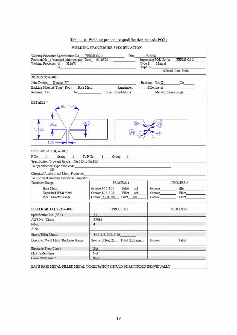
(4) Welding equipment
1) The type and capacity of welding machine and equipment for post heat treatment must conform
to its welding procedure.
Table- 9: Welding procedure specification (WPS)
18
Table- 10: Welding procedure qualification record (PQR)
19
3. Welders qualification
(1) Who performing welding work must carry out welding qualification test depending on the
classification as shown in Table-11, according to the testing method as shown in Table-12, 13, 14, 15
and must perform the welding by the qualified welder (limited to 2 years from the date that conforms
to the test).
20
Table- 11: Qualification testing matters for welder (welding method)
Classificatio
n of items to
be confirmed
Classification of detail
Welding
method
Classification of welding method must be as listed
Type
Covered metal rod (both-side welding or one-side welding with backing strip)
Covered metal rod (both-side welding or one-side welding)
Gas welding
manual
semi-auto
manual
semi-auto
manual
semi-auto
manual
semi-auto
Mig welding (both-side welding or onside welding with backing strip)
Mig welding (both-side welding or onside welding)
Plasma arc welding
TFB
Classification of welding method
A
Ao + A
G
M
Mo + M
PA
Tig welding (both-side welding or one-side welding) or first layer Tig welding
Tig welding (both-side welding or one-side welding with backing strip) or firstlayer Tig welding (with backing strip
First layer Tig welding
First layer Tig welding (with backing strip)
(T, TB, TF) + TFB
TB + TFB
TF + TFB
Reference: Appendix-13 of Interpretation of technical regulation for thermal power facility (10/Jul/1007): NISA (Nuclear
and Industrial Safety Agency) of METI Japan
21
Table- 12: Qualification testing matters for welder (test piece and welding position)
(Other than aluminum and aluminum alloy)
Classification of
items to be
confirmed
Classification of detail
Test piece and
welding position
Classification of test piece and welding position must be the combination of the classification of test
piece and classification of welding position as shown in the following table.
Workable range
f downward In downward position, in base metal thickness less than 7mm
v vertical In vertical position of plate, in base metal thickness less than 7mm
h horizontal In horizontal position of plate, in base metal thickness less than 7mm
o upward In upward position of plate, in base metal thickness less than 7mm
f downward In downward position, in base metal thickness less than 19mm
v vertical In vertical position of plate, in base metal thickness less than 19mm
h horizontal In horizontal position of plate, in base metal thickness less than 19mm
o upward In upward position of plate, in base metal thickness less than 19mm
f downward In downward position, no limitation of thickness for base metal
v vertical In vertical position of plate, no limitation of thickness for base metal
h horizontal In horizontal position of plate, no limitation of thickness for base metal
o upward In upward position of plate, no limitation of thickness for base metal
rHorizontal fixing withwall and vertical fixingwith wall
No restrictions of position and thickness of base metal is less than 11mm
eHorizontal fixing andvertical fixing
No restrictions of position and thickness of base metal is less than 11mm(except in the case that there is restriction)
rHorizontal fixing withwall and vertical fixingwith wall
No restrictions of position and thickness of base metal is less than 19mm
eHorizontal fixing andvertical fixing
No restrictions of position and thickness of base metal is less than 19mm(except in the case that there is restriction)
rHorizontal fixing withwall and vertical fixingwith wall
No restrictions of position and base metal thickness
e Horizontal fixing andvertical fixing
No restrictions of position and base metal thickness (except in the casethat there is restriction)
W-11(plate with thickness9mm)
W-2(plate with thickness atleast 25mm)
W-3-0(pipe with diameter atleast 100~120mm andthickness 4~5.3mm)
W-3(pipe with diameter atleast 150~170mm andthickness 9~11mm)
W-4(pipe with diameter atleast 200~300mm andthickness at least20mm)
W-0(plate with thickness3~3.2mm)
Classification base metal Classification of position
Oth
er th
an a
lum
inum
and
alu
min
um a
lloy
Reference: Appendix-13 of Interpretation of technical regulation for thermal power facility (10/Jul/1007): NISA (Nuclear
and Industrial Safety Agency) of METI Japan
22
Table- 13: Qualification testing matters for welder (test piece and welding position)
(Aluminum and aluminum alloy)
Classification of
items to be
confirmed
Classification of detail
Test piece and
welding position
Classification of test piece and welding position must be the combination of the classification of test
piece and classification of welding position as shown in the following table.
Workable range
f downward In downward position, in base metal thickness less than 7mm
v vertical In vertical position of plate, in base metal thickness less than 7mm
h horizontal In horizontal position of plate, in base metal thickness less than 7mm
o upward In upward position of plate, in base metal thickness less than 7mm
f downward In downward position, in base metal thickness less than 17mm
v vertical In vertical position of plate, in base metal thickness less than 17mm
h horizontal In horizontal position of plate, in base metal thickness less than 17mm
o upward In upward position of plate, in base metal thickness less than 17mm
f downward In downward position, no limitation of thickness for base metal
v vertical In vertical position of plate, no limitation of thickness for base metal
h horizontal In horizontal position of plate, no limitation of thickness for base metal
o upward In upward position of plate, no limitation of thickness for base metal
rHorizontal fixing withwall and vertical fixingwith wall
No restrictions of position and thickness of base metal is less than 9mm
rHorizontal fixing withwall and vertical fixingwith wall
No restrictions of position and thickness of base metal is less than 25mm
rHorizontal fixing withwall and vertical fixingwith wall
No restrictions of position and base metal thickness
Horizontal fixing andvertical fixing
No restrictions of position and thickness of base metal is less than 9mm(except in the case that there is restriction)
eNo restrictions of position and thickness of base metal is less than 25mm(except in the case that there is restriction)
eNo restrictions of position and base metal thickness (except in the casethat there is restriction)
W-10(plate with 3mmthickness)
W-11(plate with 8mmthickness)
W-12(plate with thickness atleast 20mm)
W-13(pipe with diameter atleast 100~150mm andthickness 4mm)
W-14(pipe with diameter atleast 150~200mm andthickness 12~15mm)
Classification base metal Classification of position
Alu
min
um a
nd a
lum
inum
allo
y
e
W-15(pipe with diameter atleast 200~300mm andthickness at least20mm) Horizontal fixing and
vertical fixing
Horizontal fixing andvertical fixing
Reference: Appendix-13 of Interpretation of technical regulation for thermal power facility (10/Jul/1007): NISA (Nuclear
and Industrial Safety Agency) of METI Japan
23
Table- 14: Qualification testing matters for welder (welding rod)
Classification of
items to be
confirmed
Classification of detail
Welding rod 1. Classification of welding rod must be as shown in following table and no stipulation in the table
must be one classification of the combination and the type and composition.
Type
F-0 Illuminate type welding rod,
F-0 and F-1Illuminate type welding rod, high oxidation type rod, high oxide-titanium welding rod (for mild steel and high tension steel(flat, horizontal fillet), iron powder low hydrogen type welding rod (other than molybdenum and chromium steel), ironpowder iron-oxide welding rod
F-0 ~ F-2Illuminate type welding rod, high oxidation iron type rod, high oxide-titanium welding rod, iron powder low hydrogen typewelding rod (other than molybdenum steel and chromium-molybdenum alloy), iron powder iron-oxide welding rod,limetitania type welding rod, high oxide-titanium welding rod
F-0 ~ F-3Illuminate type welding rod, high oxidation iron type rod, high oxide-titanium welding rod, iron powder low hydrogen typewelding rod (other than molybdenum steel and chromium-molybdenum alloy), iron powder iron-oxide welding rod,limetitania type welding rod, high oxide-titanium welding rod, high cellulose type welding rod
F-0 ~ F-4Illuminate type welding rod, high oxidation iron type rod, high oxide-titanium welding rod, iron powder low hydrogen typewelding rod, iron powder iron-oxide welding rod, limetitania type welding rod, high oxide-titanium welding rod, highcellulose type welding rod, low hydrogen type welding rod
F-5 Welding rod stainless steel
F-6-1 High ductility gas welding rod
F-6-2 Low ductility gas welding rod
Covered metal rod F-40X Welding rod for nickel, Welding rod for nickel-copper alloy, Welding rod for nickel-chromium-iron alloy, Welding rod fornickel-molybdenum-iron alloy, welding rod for nickel-chromium -molybdenum-iron alloy
Classification of welding rod
Covered metal rod
Gas welding rod
Reference: Appendix-13 of Interpretation of technical regulation for thermal power facility (10/Jul/1007): NISA (Nuclear
and Industrial Safety Agency) of METI Japan
Table- 15: Qualification testing matters for welder (Filler metal (including weld insert) or core wire)
Classification of
items to be
confirmed
Classification of detail
Filler metal
(including weld
insert) or core wire
2. Classification of filler metal and core wire must be as shown in following table and no stipulation
in the table must be one classification of the combination and the type and composition.
Filler metal Core wire
Carbon steel (component of weld metal is equivalent to A-1 listed in Table-**)
Molybdenum steel (component of weld metal is equivalent to A-2 listed in Table-**)
Cr-molybdenum steel (component of weld metal is equivalent to A-3 listed in Table-**)
Cr-molybdenum steel (component of weld metal is equivalent to A-4-1 listed in Table-**)
Martensitic stainless steel (component of weld metal is equivalent to A-5 listed in Table-**)
Frrritic stainless steel (component of weld metal is equivalent to A-6 listed in Table-**)
Austenitic stainless steel (component of weld metal is equivalent to A-7~ A-8 listed in Table-**)
Aluminum
Aluminum magnesium alloy
Aluminum silicate alloy
Copper
Silicon bronze
Phosphor bronze
Cupronickel
Aluminum bronze
Special aluminum bronze
Nickel
Nickel-copper alloy
Nickel-Cr-iron alloy
Nickel-Mo-iron alloy
Iron-nickel Cr-Mo alloy
R-51 E-51 Titanium
Detail classification
R-30X E-30X
R-40X E-40X
R-5X E-5X
R-20X E-20X
E-1XR-1X
Classification
24
Reference: Appendix-13 of Interpretation of technical regulation for thermal power facility (10/Jul/1007): NISA (Nuclear
and Industrial Safety Agency) of METI Japan
(2) When it has been confirmed that welder has skill listed in the following cases, it must be deemed to
have been carried out by qualified welders, notwithstanding the provisions of the preceding
paragraph.
1) In the following cases of welder who do not use automatic welding machine;
a. Who passed the qualification test of welder according to “Rules for steel ship structure JP”
and “Rules for safety of boiler &pressure vessel JP”, passed the classification as listed in
Table-11 and who perform welding depending on the Table-16.
b. Who passed the evaluation test conforming to JIS Z3801-1997 “Standard qualification
procedure for manual welding technique”, JIS Z3811-2000 “Standard qualification
procedure for welding technique of aluminum and aluminum alloy”, JIS Z3821-2000
“Standard qualification procedure for welding technique of stainless steel”, JIS
Z3841-1997“Standard qualification procedure for semi-automatic welding technique”,
who has been issued a certificate of eligibility and who perform the welding depending on
the Table-17, 18, 19, 20.
c. Who passed qualification test such as TCVN, ASME, API, ISO, EN, AWS, ABS and has
valid license, certificate is capable to perform welding depending on the qualified
classification.
Table- 16: Correspondence of welders’ skill classification
Hand welder’s skill to be confirmed Approval testing of welder passed under other laws and regulations
AW-1 fvho F-0
Rules for steel ship structure
M2-type O-class-A
AW-2 fvho F-0 M3-type O-class-A
AW-1 fv F-0 M2-type V-class-A
AW-2 fv F-0 M3-type V-class-A
AW-2 fvho F-0 Rules for safety of boiler & pressure vessel
Special boiler welder
AW-1 fvho F-0 Ordinary boiler welder
Note: If welding rods used for test is clear that the appropriate to F-1 to F-4 in the Table-18, F-0 must be read such
classification.
Reference: Appendix-15 of Interpretation of technical regulation for thermal power facility (10/Jul/1007): NISA (Nuclear
and Industrial Safety Agency) of METI Japan
25
Table- 17: Correspondence of qualification classification between interpretations of
technical regulation and JIS Z3801
《JIS Z3801》
JIS
Qualification
classification
A N G
Classification of qualification in interpretation of technical regulation
1F ― ― ― Ao W-0 f G W-0 f
2F A W-1 f Ao W-1 f G W-1 f
3F A W-2 f Ao W-2 f ― ― ―
1V ― ― ― Ao W-0 v G W-0 v
2V A W-1 v Ao W-1 v G W-1 v
3V A W-2 v Ao W-2 v ― ― ―
1H ― ― ― Ao W-0 h G W-0 h
2H A W-1 h Ao W-1 h G W-1 h
3H A W-2 h Ao W-2 h ― ― ―
1O ― ― ― Ao W-0 o G W-0 o
2O A W-1 o Ao W-1 o G W-1 o
3O A W-2 o Ao W-2 o ― ― ―
1P ― ― ― Ao W-3-0 e G W-0 e
2P A W-3 e Ao W-3 e G W-1 e
3P A W-4 e Ao W-4 e ― ― ―
Note:
(1) Classification of welding rod must be those which used for examination in the Table-25.
(2) “―” means that there is no equivalent examination in JIS.
(3) In case of welding method “G”, thickness of base metal corresponding workable range must be less than the
thickness of test piece.
Reference: Appendix-16 of Interpretation of technical regulation for thermal power facility (10/Jul/1007): NISA (Nuclear
and Industrial Safety Agency) of METI Japan
26
Table- 18: Correspondence of qualification classification between interpretations of
technical regulation and JIS Z3811
《JIS Z3811》
JIS Qualification classification
TN MN MA
Classification of qualification in interpretation of technical regulation
1F T W-10 f Mo W-10 f M W-10 f
2F T W-11 f Mo W-11 f M W-11 f
3F T W-12 f Mo W-12 f M W-12 f
1V T W-10 v Mo W-10 v M W-10 v
2V T W-11 v Mo W-11 v M W-11 v
3V T W-12 v Mo W-12 v M W-12 v
1H T W-10 h Mo W-10 h M W-10 h
2H T W-11 h Mo W-11 h M W-11 h
3H T W-12 h Mo W-12 h M W-12 h
1O T W-10 o Mo W-10 o M W-10 o
2O T W-11 o Mo W-11 o M W-11 o
3O T W-12 o Mo W-12 o M W-12 o
1P T W-10 e ― ― ― M W-13 e
2P T W-11 e Mo W-14 e M W-14 e
3P T W-12 e Mo W-15 e ― ― ―
Note:
(1) The classification of filler metal of welding method MO and M must be pursuant to the welding rod, filler metal and
core wire as shown in Table-27.
(2) The Tig welding of first layer under JIS MN-2P and MN-3P does not correspond to classification of qualification in
interpretation of technical regulation
(3) “―” shows no application of testing in JIS
Reference: Appendix-16 of Interpretation of technical regulation for thermal power facility (10/Jul/1007): NISA (Nuclear
and Industrial Safety Agency) of METI Japan
27
Table- 19: Correspondence of qualification classification between interpretations of
technical regulation and JIS Z3821
《JIS Z3821》
JIS Qualification classification
CN CA TN MN MA
Classification of qualification in interpretation of technical regulation
F Ao W-1 f ― ― ― T W-0 f Mo W-1 f M W-1 f
V Ao W-1 v ― ― ― T W-0 v Mo W-1 v M W-1 v
H Ao W-1 h ― ― ― T W-0 h Mo W-1 h M W-1 h
O Ao W-1 o A W-1 o T W-0 o ― ― ― ― ― ―
P Ao W-3 e ― ― ― T W-3-0 e ― ― ― ― ― ―
Note:
(1) The classification of welding rod of welding method AO and A, the classification of filler metal of welding method T
and the classification of core wire of welding method MO and M must be pursuant to the welding rod, filler metal and
core wire as shown in Table-25 or 27.
(2) “―” shows no application of testing in JIS
Reference: Appendix-16 of Interpretation of technical regulation for thermal power facility (10/Jul/1007): NISA (Nuclear
and Industrial Safety Agency) of METI Japan
Table- 20: Correspondence of qualification classification between interpretations of
technical regulation and JIS Z3841
《JIS Z3841》
JIS Qualification classification
SN SA
Classification of qualification in interpretation of technical regulation
1F Mo W-0 f ― ― ―
2F Mo W-1 f M W-1 f
3F Mo W-2 f M W-2 f
1V Mo W-0 v ― ― ―
2V Mo W-1 v M W-1 v
3V Mo W-2 v M W-2 v
1H Mo W-0 h ― ― ―
2H Mo W-1 h M W-1 h
3H Mo W-2 h M W-2 h
1O Mo W-0 o ― ― ―
2O Mo W-1 o M W-1 o
3O Mo W-2 o M W-2 o
1P Mo W-3-0 e ― ― ―
2P Mo W-3 e M W-3 e
3P Mo W-4 e M W-4 e
28
Note:
(1) The classification of core wire of welding method MO and M must pursuant to the classification of filler metal as
shown in Table-27.
(2) “―” shows no application of testing in JIS
Reference: Appendix-16 of Interpretation of technical regulation for thermal power facility (10/Jul/1007): NISA (Nuclear
and Industrial Safety Agency) of METI Japan
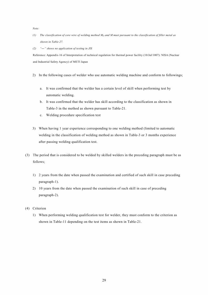
2) In the following cases of welder who use automatic welding machine and conform to followings;
a. It was confirmed that the welder has a certain level of skill when performing test by
automatic welding.
b. It was confirmed that the welder has skill according to the classification as shown in
Table-3 in the method as shown pursuant to Table-21.
c. Welding procedure specification test
3) When having 1 year experience corresponding to one welding method (limited to automatic
welding in the classification of welding method as shown in Table-3 or 3 months experience
after passing welding qualification test.
(3) The period that is considered to be welded by skilled welders in the preceding paragraph must be as
follows;
1) 2 years from the date when passed the examination and certified of such skill in case preceding
paragraph-1).
2) 10 years from the date when passed the examination of such skill in case of preceding
paragraph-2).
(4) Criterion
1) When performing welding qualification test for welder, they must conform to the criterion as
shown in Table-11 depending on the test items as shown in Table-21.
29
Table- 21: Approval testing of welder and criterion (other than aluminum or aluminum alloy)
Classification
of test piece Test method Criterion
Other than
aluminum or
aluminum alloy
Test method must be pursuant to JIS Z3801-1997 “standard qualification
procedure for manual welding technique” except following cases;
1. Welding method, test piece, welding position, welding rod, filler metal
and core wire must be pursuant to the detail classification according to
the classification of test items in Table-11.
2. In case of 1., classification of welding method listed in left column of the
following table must conform to the method listed in the right column.
Classification of welding method Welding method
Ao and A Ao
T, TB, TF and TFB T
TB and TFB TB
TF and TFB TF
Mo and M Mo
3. In case of 1., classification of welding rod listed in left column of the
following table must conform according to the method listed in the right
column.
Classification of welding rod Welding rod
F-0 F-0
F- 0 and F-1 F-1
F-0 ~ F-2 F-2
F-0 ~ F-3 F-3
F-0 ~ F-4 F-4
F-5 F-5
F-6-1 F-6-1
F-6-2 F-6-2
F-41 ~ F-45 any of F-41 ~ F-45 4. In case of 1., classification of filler metal listed in left column of the
following table must conform according to the method listed in the right
column.
Classification of filler metal Filler metal
R-1 ~ R-4-2 and R-10 any of R-1 ~ R-4-2 and R-10
R-5 ~ R-8 any of R-5 ~ R-8
R-21 ~ R-23 any of R-21 ~ R-23
R-31 ~ R-34, R-36 and R-37 any of R-31 ~ R-34, R-36 and R-37
R-41 ~ R-45 any of R-41 ~ R-45
R-51 R-51
5. In case of 1., classification of core wire listed in left column of the
following table must conform according to the method listed in the right
column.
According to JIS Z3801
Cracks occur on the corner
edge must be excluded
from the criterion in the
bend test (no more than
3.0mm length crack).
30
Classification
of test piece Test method Criterion
Classification of core wire Core wire
E-1 ~ E-4-2 and E-10 any of E-1 ~ E-4-2 and E-10
E-3 ~ E-8 any of E-3 ~ E-8
E-21 ~ E-23 any of E-21 ~ E-23
E-31 ~ E-34, E-36 and E-37 any of E-31 ~ E-34, E-36 and E-37
E-41 ~ E-45 any of E-41 ~ E-45
E-51 E-51
6. Type of test piece must be appropriate for the welding.
7. If the classification of combination of test piece and welding position is
W-3-0r, W-3r and W-4r, the dimension, location to install and specimen
collection position must be pursuant to Fig-4.
8. If the classification of welding method is other than A, ( Ao+A) and G as
shown in Table-11, shape and dimension of joint must be appropriate for
such welding method, and (TB+TFB), TFB, M or PA must be one side
welding.
9. If the classification of welding method is (TF +TFB) and TFB as shown in
Table-11, must be pursuant as follows;
(1) The name of welder, welding method and welding position of other than
first layer does not matter. The welding other than first layer must be
performed by welders who have reliable workmanship and the weld metal
must be comparable to that of the first layer in this case.
(2) The number of specimens must be the sum of specimens for face bend,
side bend, root bend as shown in Fig-4 and attachment drawing-3, 4, 5, 6,
7 or 8 of JIS Z3802. All specimens must be tested by root bend test.
Reference: Appendix-14 of Interpretation of technical regulation for thermal power facility (10/Jul/1007): NISA (Nuclear
and Industrial Safety Agency) of METI Japan
31
Table- 22: Approval testing of welder and criterion (aluminum or aluminum alloy)
Classification
of test piece Test method Criterion
Aluminum or
aluminum alloy
Test method must be pursuant to JIS Z3811-2000 “standard qualification
procedure for manual welding technique” except following cases;
1. Welding method, test piece, welding position, filler metal or core wire
must be pursuant to the detail classification as shown in Table-11.
2. If the classification of test piece is W-13r, W-14r and W-15r as shown in
Table-23, the dimension, location to install method and specimen
collection position must be pursuant to Fig-4.
3. If the classification of test piece is other than aluminum or aluminum
alloy, item-5 and -6 of above table must be applied mutatis mutandis.
According to JIS Z3811
Cracks occur on the corner
edge must be excluded
from the criterion in the
bend test (no more than
3.0mm length crack).
Reference: Appendix-13 of Interpretation of technical regulation for thermal power facility (10/Jul/1007): NISA (Nuclear
and Industrial Safety Agency) of METI Japan
(5) Accreditation of skills
1) The welder who passed the welding qualification test can weld according to qualified skill
2 years from the date when conforming or passing to the latest inspection before the day on
which expires 2 years.
2) When conforming to the inspection of Electric Utility Law.
3) When passing to either following inspection;
a. Inspection according to ship safety law; or
b. Inspection according to rules for safety of boiler & pressure vessel; or
c. Inspection according to high pressure gas safety law; or
d. Inspection according to Japan Welding Engineering Society or;
e. Inspection according to Japan Petroleum Institute; or
f. Equivalent inspection according to TCVN, ASME, AWS, API, ABS, EN, ISO and the like.
4) 3) must be applied mutatis mutandis to the automatic welding. In this case, “2 years” must be
read “10 years”.
(6) Workable range
The workable range such as position, thickness of base metal of welding that is performed by the
qualified welder must be the range as shown in Table-23 depending on the test piece or position in
32
that Table.
Table- 23: Classification of test material, position and workable range
(other than aluminum or aluminum alloy)
Classification base metal Classification of position Workable range
Oth
er th
an a
lum
inum
and
alu
min
um a
lloy
W-0
(plate with
thickness 3~3.2mm)
f downward In downward position, in base metal thickness less
than 7mm
v vertical In vertical position of plate, in base metal thickness
less than 7mm
h horizontal In horizontal position of plate, in base metal
thickness less than 7mm
o upward In upward position of plate, in base metal thickness
less than 7mm
W-1
(plate with thickness
9mm)
f downward In downward position, in base metal thickness less
than 19mm
v vertical In vertical position of plate, in base metal thickness
less than 19mm
h horizontal In horizontal position of plate, in base metal
thickness less than 19mm
o upward In upward position of plate, in base metal thickness
less than 19mm
W-2
(plate with thickness
at least 25mm)
f downward In downward position, no limitation of thickness
for base metal
v vertical In vertical position of plate, no limitation of
thickness for base metal
h horizontal In horizontal position of plate, no limitation of
thickness for base metal
o upward In upward position of plate, no limitation of
thickness for base metal
W-3-0 r Horizontal fixing with wall and No restrictions of position and thickness of base
33
Classification base metal Classification of position Workable range
(pipe with diameter at
least 100~120mm and
thickness 4~5.3mm)
vertical fixing with wall metal is less than 11mm
e Horizontal fixing and
vertical fixing
No restrictions of position and thickness of base
metal is less than 11mm (except in the case that
there is restriction)
W-3
(pipe with diameter at
least 150~170mm and
thickness 9~11mm)
r Horizontal fixing with wall and
vertical fixing with wall
No restrictions of position and thickness of base
metal is less than 19mm
e Horizontal fixing and
vertical fixing
No restrictions of position and thickness of base
metal is less than 19mm (except in the case that
there is restriction)
W-4
(pipe with diameter at
least 200~300mm and
thickness at least
20mm)
r Horizontal fixing with wall and
vertical fixing with wall
No restrictions of position and base metal thickness
e Horizontal fixing and
vertical fixing
No restrictions of position and base metal thickness
(except in the case that there is restriction)
Reference: Appendix-17 of Interpretation of technical regulation for thermal power facility (10/Jul/1007): NISA (Nuclear
and Industrial Safety Agency) of METI Japan
34
Table- 24: Classification of test material, position and workable range
(aluminum or aluminum alloy)
Classification base metal Classification of position Workable range
Alu
min
um a
nd a
lum
inum
allo
y
W-10 (plate with 3mm thickness)
f downward In downward position, in base metal thickness less than 7mm
v vertical In vertical position of plate, in base metal thickness less than 7mm
h horizontal In horizontal position of plate, in base metal thickness less than 7mm
o upward In upward position of plate, in base metal thickness less than 7mm
W-11 (plate with 8mm thickness)
f downward In downward position, in base metal thickness less than 17mm
v vertical In vertical position of plate, in base metal thickness less than 17mm
h horizontal In horizontal position of plate, in base metal thickness less than 17mm
o upward In upward position of plate, in base metal thickness less than 17mm
W-12 (plate with thickness at least 20mm)
f downward In downward position, no limitation of thickness for base metal
v vertical In vertical position of plate, no limitation of thickness for base metal
h horizontal In horizontal position of plate, no limitation of thickness for base metal
o upward In upward position of plate, no limitation of thickness for base metal
W-13 (pipe with diameter at least 100~150mm and thickness 4mm)
r Horizontal fixing with wall and vertical fixing with wall
No restrictions of position and thickness of base metal is less than 9mm
e Horizontal fixing and vertical fixing
No restrictions of position and thickness of base metal is less than 9mm (except in the case that there is restriction)
W-14 (pipe with diameter at least 150~200mm and thickness 12~15mm)
r Horizontal fixing with wall and vertical fixing with wall
No restrictions of position and thickness of base metal is less than 25mm
e Horizontal fixing and vertical fixing
No restrictions of position and thickness of base metal is less than 25mm (except in the case that there is restriction)
W-15 (pipe with diameter at least 200~300mm and thickness at least 20mm)
r Horizontal fixing with wall and vertical fixing with wall
No restrictions of position and base metal thickness
e Horizontal fixing and vertical fixing
No restrictions of position and base metal thickness (except in the case that there is restriction)
Note:
(1) “Restriction” means the variety of limitations of the work in high place, narrow place and where it is difficult work.
(2) In case of TTF + TFB) as shown in Table-13, the workable scope W-0, W-1, W-3-0, W-3, W-10, W-11, W-13 and W-14
as shown in above table must be considered as no limitation for the thickness 0f base metal.
35
(3) In case of gas welding, “base metal thickness less than 19mm” as shown above or “no limitation of thickness” must be
red “thickness of base metal is less than thickness of test piece”.
(4) The workable scope in case of test classification W-0 or W-10 in the above Table-**, if 4 position such as f, v, h and o,
the workable scope must be red “no limitation”.
Table- 25: Classification of welding rod
Classification of welding rod Type
Cov
ered
met
al ro
d
F-0 Ilmenite type welding rod
F-1
High oxidation iron lime type rod
Iron powder oxide-titanium welding rod (for mild steel and high tension steel (downward, horizontal fillet))
Iron powder low hydrogen type welding rod (except for molybdenum and chromium-molybdenum steel)
Iron powder iron-oxide welding rod
F-2
Limetitania type welding rod
High oxide-titanium welding rod
Iron powder oxide-titanium welding rod (for high tension steel ( all position))
F-3 High cellulose type welding rod
F-4
Low hydrogen type welding rod
Iron powder low hydrogen type welding rod (for molybdenum and chromium-molybdenum alloy)
F-5 Welding rod for stainless steel
Gas
wel
ding
rod
F-6-1 High ductility gas welding rod
F-6-2 Low ductility gas welding rod
Cov
ered
met
al ro
d F-41 Welding rod for nickel
F-42 Welding rod for nickel-copper alloy
F-43 Welding rod for nickel-chromium-iron alloy
F-44 Welding rod for nickel –molybdenum-iron alloy
F-45 Welding rod for nickel –chromium-molybdenum-iron alloy
Reference: Appendix-18 of Interpretation of technical regulation for thermal power facility (10/Jul/1007): NISA (Nuclear
A-10 Nickel steel ≤ 0.15 ― ≤ 0.55 0.80~4.00 ≤ 1.70 ≤ 1.00 Reference: Appendix-19 of Interpretation of technical regulation for thermal power facility (10/Jul/1007): NISA (Nuclear and Industrial Safety Agency) of METI Japan
Table- 27: Classification of filler metal or weld inserts
Classification of filler metal or weld insert
Type of core wire Type
R-1 E-1 Carbon steel (component of weld metal is equivalent to A-1 listed in Table-26)
R-2 E-2 Molybdenum steel (component of weld metal is equivalent to A-2 listed in Table-26)
R-3 E-3 Cr-molybdenum steel (component of weld metal is equivalent to A-3 listed in Table-26)
R-4-1 E-4-1 Cr-molybdenum steel (component of weld metal is equivalent to A-4-1 listed in Table-26)
R-4-2 E-4-2 Cr-molybdenum steel (component of weld metal is equivalent to A-4-2 listed in Table-26)
R-5 E-5 Martensitic stainless steel (component of weld metal is equivalent to A-5 listed in Table-26)
R-6 E-6 Frrritic stainless steel (component of weld metal is equivalent to A-6 listed in Table-26)
R-7 E-7 Austenitic stainless steel (component of weld metal is equivalent to A-7 listed in Table-26)
R-8 E-8 Austenitic stainless steel (component of weld metal is equivalent to A-8 listed in Table-26)
R-10 E-10 Nickel copper (component of weld metal is equivalent to A-10 listed in Table-26)
R-21 E-21 Aluminum
R-22 E-22 Aluminum magnesium alloy
R-23 E-23 Aluminum silicate alloy
R-31 E-31 Copper
R-32 E-32 Silicon bronze
R-33 E-33 Phosphor bronze
R-34 E-34 Cupronickel
R-36 E-36 Aluminum bronze
R-37 E-37 Special aluminum bronze
R-41 E-41 Nickel
R-42 E-42 Nickel-copper alloy
R-43 E-43 Nickel-Cr-iron alloy
R-44 E-44 Nickel-Mo-iron alloy
R-45 E-45 Iron-nickel Cr-Mo alloy
R-51 E-51 Titanium
37
Reference: Appendix-20 of Interpretation of technical regulation for thermal power facility (10/Jul/1007): NISA (Nuclear and Industrial Safety Agency) of METI Japan
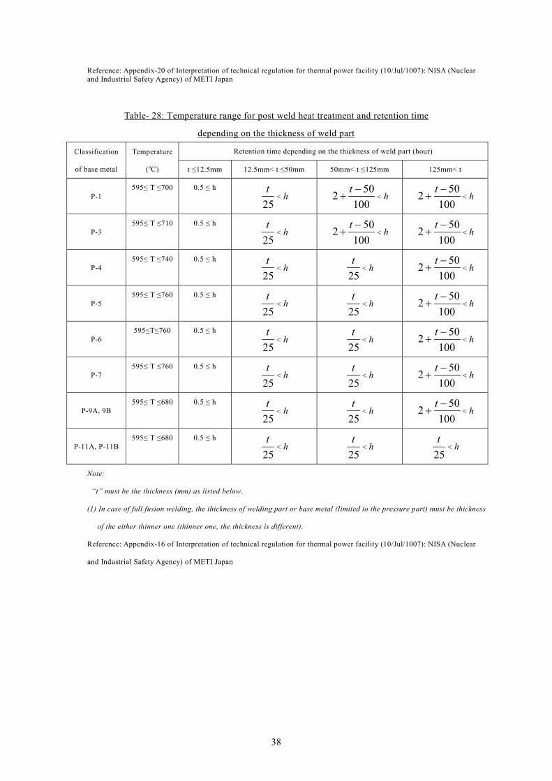
Table- 28: Temperature range for post weld heat treatment and retention time
depending on the thickness of weld part
Classification
of base metal
Temperature
(oC)
Retention time depending on the thickness of weld part (hour)
t ≤12.5mm 12.5mm< t ≤50mm 50mm< t ≤125mm 125mm< t
P-1 595≤ T ≤700 0.5 ≤ h
25t
< h 100
502 −+
t< h
100502 −
+t
< h
P-3 595≤ T ≤710 0.5 ≤ h
25t
< h 100
502 −+
t< h
100502 −
+t
< h
P-4 595≤ T ≤740 0.5 ≤ h
25t
< h 25t
< h 100
502 −+
t< h
P-5 595≤ T ≤760 0.5 ≤ h
25t
< h 25t
< h 100
502 −+
t< h
P-6 595≤T≤760 0.5 ≤ h
25t
< h 25t
< h 100
502 −+
t< h
P-7 595≤ T ≤760 0.5 ≤ h
25t
< h 25t
< h 100
502 −+
t< h
P-9A, 9B 595≤ T ≤680 0.5 ≤ h
25t
< h 25t
< h 100
502 −+
t< h
P-11A, P-11B 595≤ T ≤680 0.5 ≤ h
25t
< h 25t
< h 25t
< h
Note:
“t” must be the thickness (mm) as listed below.
(1) In case of full fusion welding, the thickness of welding part or base metal (limited to the pressure part) must be thickness
of the either thinner one (thinner one, the thickness is different).
Reference: Appendix-16 of Interpretation of technical regulation for thermal power facility (10/Jul/1007): NISA (Nuclear
and Industrial Safety Agency) of METI Japan
38
Table- 29: Welder and welding operator performance qualification record
39
Note:
1. When performing Tig welding of the first layer for the test piece with thickness less than 19mm, “test specimen for
face bend” must be read “test specimen for root bend”.
2. The number of the impact test specimen must be 3 taken from heat affected zone and weld metal part. However, when
using different base metals, 3 specimens from heat affected zone and weld metal part of each base metal. In addition,
when different welding method is applied (in case of welding methods used in only the first layer, it is not necessary to
collect specimen), 3 specimens from heat affected zone and weld metal part of intersection of each welding methods.
Reference: Appendix-Fig-1 of Interpretation of technical regulation for thermal power facility (10/Jul/1007): NISA (Nuclear
and Industrial Safety Agency) of METI Japan
Fig- 4: Test piece and specimen for plate
40
Note:
1. When performing Tig welding of the first layer for the test piece with thickness less than 19mm, “test specimen for face bend of (2) and (5)” must be read “test specimen for root bend”.
2. The number of impact test specimen may be same as plate as shown in Fig-4.
3. The position to collect impact test specimen may be either (7) or (8).
4. The position to collect test specimen in case performing welding in the horizontal rotation, the absolute position of specimen does not matter as shown the relative position in the figure.
5. A fixed horizontal plane in case performing the welding in the horizontal mounting must be as shown in figure.
Reference: Appendix-Fig-2 of Interpretation of technical regulation for thermal power facility (10/Jul/1007): NISA (Nuclear and Industrial Safety Agency) of METI Japan
Fig- 5: Test piece and specimen for pipe
41
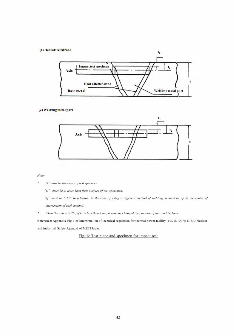
Note:
1. “t” must be thickness of test specimen.
“t1” must be at least 1mm from surface of test specimen.
“t2”must be 0.25t. In addition, in the case of using a different method of welding, it must be up to the center of
intersection of each method.
2. When the axis is 0.25t, if t1 is less than 1mm, it must be changed the position of axis and be 1mm.
Reference: Appendix-Fig-3 of Interpretation of technical regulation for thermal power facility (10/Jul/1007): NISA (Nuclear
and Industrial Safety Agency) of METI Japan
Fig- 6: Test piece and specimen for impact test
42
Note:
1. Dimension must be in mm.
2. Test piece, in addition to the provisions in this figure, must be applied mutatis mutandis to JIS Z3801-1997 “test methods and criteria in the test of manual welding technology”.
3. Test piece must be welded between A to B and A to D by appropriate method, fixed horizontally as shown Fig-a). D must be the lowest point of horizontal axis. Then, BCD must be welded after fixing test piece in vertical position as shown in Fig-b). C point must be located to the direction of corner of the wall. Welding may be started from any point either B or D.
4. If the classification of welding method is M or M+MO as shown in Table-11, distance from ceiling and wall to test piece must be read “500” instead of “300”.
5. In case of W-13r, W-14r and W-15r, distance from ceiling and wall “300” must be read “500 (if the classification of welding method is T or TF as shown in Table-3, “400” )”, distance from wall or floor “150” must be read “350 (if the classification of welding method is T or TF as shown in Table-3, “300” )”.
6. “Face bends or side bends” shown in the figure must be the bending for W-3-0r, W-3r, W-13r and W-14r, the side bending for W-4r and W-15r.
Reference: Appendix-Fig-4 of Interpretation of technical regulation for thermal power facility (10/Jul/1007): NISA (Nuclear and Industrial Safety Agency) of METI Japan
Fig- 7: Installation of test piece for pipe (W-3-0r, W-3r, W-13r, W-14r and W-15r)
43
Fillet Welding
Groove Welding
Fig- 8: Welding position according to ASME
44
Table- 30: Comparison of various welders’ qualification system
Standard
Item Electric Utility Law Labor Safety and
Health Act
High Pressure Gas
Safety Law
Japan Petroleum
Institute
(JPI)
Japan Welding
Engineering Society
(JWES)
Nippon Kaiji Kyokai
(ClassNK)
(NK)
Japanese Industrial
Standards
(JIS)
Regulations compliance Interpretation of technical regulation for thermal power facility
Object Boiler, piping, pressure vessel, heat exchanger, liquefied gas facility for power generation
Boiler, piping,
pressure vessel
Pressure vessel and piping for high pressure facility
Storage tank, vessel, oil & gas pipeline
All welding and brazing Hull, rigging, prime mover JIS stipulate only procedure and criterion about welding procedure, welder qualification test, non-destructive test or mechanical test as standard.
Scope of accreditation
Scope classified by factory, and welding content such as material , position, welding rod, etc.
Special boiler welder and
Ordinary boiler welder
Individual qualification
Scope according to other law and regulation
Individual qualification
Scope by material, position, thickness
Individual qualification
Scope by material, position, thickness
Individual qualification
Scope by material, position, thickness
Individual qualification
Accreditation organization Operator (owner of generation facility)
Director of labor standards bureau in each prefecture
Accreditation by operator
(ckeck of official qualification)
Japan Petroleum
Institute
Japan Welding
Engineering Society
Nippon Kaiji Kyokai
(ClassNK)
Application institution
Form of application
Criteria
Interpretation of technical regulation for thermal power facility
Labor standard inspection office or designated agency
High pressure gas safety institute of Japan
Japan Petroleum
Institute
Japan Welding
Engineering Society
Nippon Kaiji Kyokai
(ClassNK)
Certification method
Witness Audit by witness in each district Document review and witness JWES performs practical test of type-E, F, Ft, FC.
JPI audit documents for other type.
Audit by witness in each district Witness
Certification result Skill approval by every product Individual licensing Skill approval by every product Issue of individual qualification certificate by each type
Issue of individual qualification certificate by each type
Issue of individual qualification certificate by each type
Expiration date, Update procedure
2 year (with automatic renewal conditions of 2 years)
1 year (witness practical examination in once every year)
According to other standard 1 year (with approval of continuation in once every 2 years)
3 year (with approval of continuation in once every year)
3 year (with automatic renewal conditions of 3 years)
45
Table- 31: Comparison of various welders’ qualification system
Standard
Item
American Welding
Society
(AWS)
American Mechanical
Engineers
(ASME)
American Petroleum
Institute
(API)
American Bureau
of Shipping
(ABS)
European Norm
(EN)
International Organization
for Standardization
(ISO)
National Standards
of Vietnam
(TCVN)
Regulations compliance Welding standard for structure—steel: Section 5 Part-C
Boiler & Pressure Vessel Code Section-9.
None QCVN-**: Design technical regulation of thermal power facility
All welding and brazing All welding and brazing All welding and brazing?
Scope of accreditation
Scope classified by factory, and welding content such as material , position, welding rod, etc.
Scope classified by factory, and welding content such as material , position, welding rod, etc.
Accreditation organization Witness by the manufacturing factory director or CWI (Certified inspector by AWS)
Witness by the manufacturing factory director or AI
Application institution None None
Form of application No application form descried necessary information
No application form descried necessary information
Criteria
Structural welding (steel)
Section-5 Part-C
Practical examination
Boiler & Pressure Vessel Code Section-9.
Practical examination
API 1104 Section 6.1 ABS rules for materials and welding Part-2 2012
EN 287-1, 6
EN 1418
ISO 9606-1 to 9606-5 TCVN 6700-1
TCVN 6700-2
Certifier Director of manufacturing factory or CWI (Certified Welding Inspector)
Director of manufacturing factory or AI(Authorized Inspector)
Certification method Witness by the manufacturing factory director or CWI (Certified Welding Inspector)
Witness by the manufacturing factory director or AI(Authorized Inspector)
Certification result Skill approval for every product Skill approval for every product
Expiration date, Update procedure
Whole life (there is requirements for obtained welding procedure engaging in more than 6 months)
3 month (with automatic renewal conditions)
46
Chapter-3. Reference International Technical Standards
The reference international standards for welding are organized in Table-32.
Table- 32: Reference International Technical Standards
Number Rev. Title
ISO 3677 1992 Filler metal for soft soldering, brazing and braze welding -- Designation
ISO 5187 1985 Welding and allied processes -- Assemblies made with soft solders and brazing filler metals -- Mechanical test methods
ISO 10564 1993 Soldering and brazing materials -- Methods for the sampling of soft solders for analysis
ISO 15614-10 2005 Specification and qualification of welding procedures for metallic materials -- Welding procedure test -- Part 10: Hyperbaric dry welding
ISO 18279 2003 Brazing -- Imperfections in brazed joints
ISO 544 2003 Welding consumables -- Technical delivery conditions for welding filler materials -- Type of product, dimensions, tolerances and markings
ISO 636 2004 Welding consumables -- Rods, wires and deposits for tungsten inert gas welding of non-alloy and fine-grain steels -- Classification
ISO 1071 2003 Welding consumables - Covered electrodes, wires, rods and tubular cored electrodes for fusion welding of cast iron - Classification
ISO 2401 1972 Covered electrodes -- Determination of the efficiency, metal recovery and deposition coefficient
ISO 2560 2002 Welding consumables -- Covered electrodes for manual metal arc welding of non-alloy and fine grain steels -- Classification
ISO 3581 2003 Welding consumables -- Covered electrodes for manual metal arc welding of stainless and heat-resisting steels -- Classification
ISO 6848 2004 Arc welding and cutting -- Nonconsumable tungsten electrodes -- Classification
ISO 14171 2002 Welding consumables -- Wire electrodes and wire-flux combinations for submerged arc welding of non alloy and fine grain steels – Classification
ISO 14172 2003 Welding consumables -- Covered electrodes for manual metal arc welding of nickel and nickel alloys – Classification
ISO 14172 2004 Welding consumables -- Fluxes for submerged arc welding -- Classification
ISO 14175 2008 Welding consumables -- Gases and gas mixtures for fusion welding and allied processes
ISO 14341 2002 Welding consumables -- Wire electrodes and deposits for gas shielded metal arc welding of non alloy and fine grain steels – Classification
ISO 15792-1 2000 Welding consumables -- Test methods -- Part 1: Test methods for all-weld metal test specimens in steel, nickel and nickel alloys
ISO 15792-2 2000 Welding consumables -- Test methods -- Part 2: Preparation of single-run and two-run technique test specimens in steel
ISO 15792-3 2000 Welding consumables -- Test methods -- Part 3: Classification testing of positional capacity and root penetration of welding consumables in a fillet weld
ISO 16834 2006 Welding consumables -- Wire electrodes, wires, rods and deposits for gas-shielded arc welding of high strength steels -- Classification
ISO 17632 2004 Welding consumables -- Tubular cored electrodes for gas shielded and non-gas shielded metal arc welding of non-alloy and fine grain steels -- Classification
ISO 17633 2004 Welding consumables -- Tubular cored electrodes and rods for gas shielded and non-gas shielded metal arc welding of stainless and heat-resisting steels --
47
Number Rev. Title Classification
ISO 17634 2004 Welding consumables -- Tubular cored electrodes for gas shielded metal arc welding of creep resisting steels -- Classification
ISO 18273 2004 Welding consumables -- Wire electrodes, wires and rods for welding of aluminum and aluminum alloys -- Classification
ISO 18274 2004 Welding consumables -- Wire and strip electrodes, wires and rods for fusion welding of nickel and nickel alloys -- Classification
ISO 18275 2005 Welding consumables -- Covered electrodes for manual metal arc welding of high-strength steels -- Classification
ISO 18276 2005 Welding consumables -- Tubular cored electrodes for gas-shielded and non-gas-shielded metal arc welding of high-strength steels -- Classification
ISO 21952 2007 Welding consumables -- Wire electrodes, wires, rods and deposits for gas-shielded arc welding of creep-resisting steels -- Classification
ISO 24034 2005 Welding consumables -- Solid wires and rods for fusion welding of titanium and titanium alloys-- Classification
ISO 24373 2008 Welding consumables -- Solid wires and rods for fusion welding of copper and copper alloys -- Classification
ISO 24598 2007 Welding consumables -- Solid wire electrodes, tubular cored electrodes and electrode/flux combinations for submerged arc welding of creep-resisting steels -- Classification
ISO 4136 2001 Destructive tests on welds in metallic materials -- Transverse tensile test
ISO 5173 2000 Destructive tests on welds in metallic materials -- Bend tests
ISO 5178 2001 Destructive tests on welds in metallic materials -- Longitudinal tensile test on weld metal in fusion welded joints
ISO 9015-1 2001 Destructive tests on welds in metallic materials -- Hardness testing -- Part 1: Hardness test on arc welded joints
ISO 9015-2 2003 Destructive tests on welds in metallic materials -- Hardness testing -- Part 2: Micro hardness testing of welded joints
ISO 9016 2001 Destructive tests on welds in metallic materials -- Impact tests -- Test specimen location, notch orientation and examination
ISO 9017 2001 Destructive tests on welds in metallic materials -- Fracture test
ISO 9018 2003 Destructive tests on welds in metallic materials -- Tensile test on cruciform and lapped joints
ISO 10675 2008 Non-destructive testing of welds -- Acceptance levels for radiographic testing -- Part 1: Steel, nickel, titanium and their alloys
ISO/TR 16060 2003 Destructive tests on welds in metallic materials -- Etchants for macroscopic and microscopic examination
ISO 17635 2003 Non-destructive testing of welds -- General rules for fusion welds in metallic materials
ISO 17636 2003 Non-destructive testing of welds -- Radiographic testing of fusion-welded joints
ISO 17637 2003 Non-destructive testing of welds -- Visual testing of fusion-welded joints
ISO 17638 2003 Non-destructive testing of welds -- Magnetic particle testing
ISO 17639 2003 Destructive tests on welds in metallic materials -- Macroscopic and microscopic examination of welds
ISO 17640 2005 Non-destructive testing of welds -- Ultrasonic testing of welded joints
ISO 17641-1 2004 Destructive tests on welds in metallic materials -- Hot cracking tests for weldments -- Arc welding processes -- Part 1: General
48
Number Rev. Title
ISO 17641-2 2005 Destructive tests on welds in metallic materials -- Hot cracking tests for weldments -- Arc welding processes -- Part 2: Self-restraint tests
ISO/TR 1764-1 2005 Destructive tests on welds in metallic materials -- Hot cracking tests for weldments -- Arc welding processes -- Part 3: Externally loaded tests
ISO 17642-1 2004 Destructive tests on welds in metallic materials -- Cold cracking tests for weldments -- Arc welding processes -- Part 1: General
ISO 17642-2 2005 Destructive tests on welds in metallic materials -- Cold cracking tests for weldments -- Arc welding processes -- Part 2: Self-restraint tests
ISO 17642-3 2005 Destructive tests on welds in metallic materials -- Cold cracking tests for weldments -- Arc welding processes -- Part 3: Externally loaded tests
ISO 17643 2005 Non-destructive testing of welds -- Eddy current testing of welds by complex-plane analysis
ISO 17655 2003 Destructive tests on welds in metallic materials -- Method for taking samples for delta ferrite measurement
ISO 22825 2006 Non-destructive testing of welds -- Ultrasonic testing -- Testing of welds in austenitic steels and nickel-based alloys
ISO 22826 2005 Destructive tests on welds in metallic materials -- Hardness testing of narrow joints welded by laser and electron beam (Vickers and Knoop hardness tests)
ISO 23277 2006 Non-destructive testing of welds -- Penetrant testing of welds -- Acceptance levels
ISO 23278 2006 Non-destructive testing of welds -- Magnetic particle testing of welds -- Acceptance levels
ISO 23279 2007 Non-destructive testing of welds -- Ultrasonic testing -- Characterization of indications in welds
ISO 669 2000 Resistance welding -- Resistance welding equipment -- Mechanical and electrical requirements
ISO 693 1982 Dimensions of seam welding wheel blanks
ISO 865 1981 Slots in platens for projection welding machines
ISO 1089 1980 Electrode taper fits for spot welding equipment -- Dimensions
ISO 5182 2008 Resistance welding -- Materials for electrodes and ancillary equipment
ISO 5183-1 1998 Resistance welding equipment -- Electrode adaptors, male taper 1:10 -- Part 1: Conical fixing, taper 1:10
ISO 5183-2 2000 Resistance spot welding -- Electrode adaptors, male taper 1:10 -- Part 2: Parallel shank fixing for end-thrust electrodes
ISO 5184 1979 Straight resistance spot welding electrodes
ISO 5821 1979 Resistance spot welding electrode caps
ISO 5822 1988 Spot welding equipment -- Taper plug gauges and taper ring gauges
ISO 5826 1999 Resistance welding equipment -- Transformers -- General specifications applicable to all transformers
ISO 5827 1983 Spot welding -- Electrode back-ups and clamps
ISO 5828 2001 Resistance welding equipment -- Secondary connecting cables with terminals connected to water-cooled lugs -- Dimensions and characteristics
ISO 5830 1984 Resistance spot welding -- Male electrode caps
ISO 6210-1 1991 Cylinders for robot resistance welding guns -- Part 1: General requirements
ISO 7284 1993 Resistance welding equipment -- Particular specifications applicable to transformers with two separate secondary windings for multi-spot welding, as used in the automobile industry
49
Number Rev. Title
ISO 7285 1995 Pneumatic cylinders for mechanized multiple spot welding
ISO 7286 1986 Graphical symbols for resistance welding equipment
ISO 7931 1985 Insulation caps and bushes for resistance welding equipment
ISO 8166 2003 Resistance welding -- Procedure for the evaluation of the life of spot welding electrodes using constant machine settings
ISO 8167 1999 Projections for resistance welding
ISO 8205-1 2002 Water-cooled secondary connection cables for resistance welding -- Part 1: Dimensions and requirements for double-conductor connection cables
ISO 8205-2 2002 Water-cooled secondary connection cables for resistance welding -- Part 2: Dimensions and requirements for single-conductor connection cables
ISO 8205-3 1993 Water-cooled secondary connection cables for resistance welding -- Part 3: Test requirements
ISO 8430-1 1988 Resistance spot welding -- Electrode holders -- Part 1: Taper fixing 1:10
ISO 8430-2 1988 Resistance spot welding -- Electrode holders -- Part 2: Morse taper fixing
ISO 8430-3 1988 Resistance spot welding -- Electrode holders -- Part 3: Parallel shank fixing for end thrust
ISO 9312 1990 Resistance welding equipment -- Insulated pins for use in electrode back-ups
ISO 9313 1989 Resistance spot welding equipment -- Cooling tubes
ISO 10656 1996 Electric resistance welding -- Integrated transformers for welding guns
ISO 12145 1998 Resistance welding equipment -- Angles for mounting spot welding electrodes
ISO 12166 1997 Resistance welding equipment -- Particular specifications applicable to transformers with one secondary winding for multi-spot welding, as used in the automobile industry
ISO 14327 2004 Resistance welding -- Procedures for determining the weldability lobe for resistance spot, projection and seam welding
ISO 14554-1 2000 Quality requirements for welding -- Resistance welding of metallic materials -- Part 1: Comprehensive quality requirements
ISO 14554-2 2000 Quality requirements for welding -- Resistance welding of metallic materials -- Part 2: Elementary quality requirements
ISO 15609-5 2004 Specification and qualification of welding procedures for metallic materials -- Welding procedure specification -- Part 5: Resistance welding
ISO 15614-12 2004 Specification and qualification of welding procedures for metallic materials -- Welding procedure test -- Part 12: Spot, seam and projection welding
ISO 15614-13 2005 Specification and qualification of welding procedures for metallic materials -- Welding procedure test -- Part 13: Resistance butt and flash welding
ISO 17653 2003 Destructive tests on welds in metallic materials -- Torsion test of resistance spot welds
ISO 17654 2003 Destructive tests on welds in metallic materials -- Resistance welding -- Pressure test on resistance seam welds
ISO 17657-1 2005 Resistance welding -- Welding current measurement for resistance welding -- Part 1: Guidelines for measurement
ISO 17657-2 2005 Resistance welding -- Welding current measurement for resistance welding -- Part 2: Welding current meter with current sensing coil
ISO 17657-3 2005 Resistance welding -- Welding current measurement for resistance welding -- Part 3: Current sensing coil
ISO 17657-4 2005 Resistance welding --Welding current measurement for resistance welding --Part 4: calibration
ISO 17657-5 2005 Resistance welding -- Welding current measurement for resistance welding -- Part 5: Verification of welding current measuring system
50
Number Rev. Title
ISO 18278-1 2004 Resistance welding -- Weldability -- Part 1: Assessment of weldability for resistance spot, seam and projection welding of metallic materials
ISO 18278-2 2004 Resistance welding -- Weldability -- Part 2: Alternative procedures for the assessment of sheet steels for spot welding
ISO 18594 2007 Resistance spot-, projection- and seam-welding -- Method for determining the transition resistance on aluminum and steel material
ISO 18595 2007 Resistance welding -- Spot welding of aluminum and aluminum alloys -- Weldability, welding and testing
ISO 22829 2007 Resistance welding -- Transformer-rectifier for welding guns with integrated transformers -- Transformer-rectifier units operating at 1000 Hz frequency
ISO/TR 581 2005 Weldability -- Metallic materials -- General principles
ISO 857-1 1998 Welding and allied processes -- Vocabulary -- Part 1: Metal welding processes
ISO 857-2 2005 Welding and allied processes -- Vocabulary -- Part 2: Soldering and brazing processes and related terms
ISO 2553 1992 Welded, brazed and soldered joints -- Symbolic representation on drawings
ISO 4063 1998 Welding and allied processes -- Nomenclature of processes and reference numbers
ISO 6520-1 2007 Welding and allied processes -- Classification of geometric imperfections in metallic materials -- Part 1: Fusion welding
ISO 6520-2 2001 Welding and allied processes -- Classification of geometric imperfections in metallic materials -- Part 2: Welding with pressure
ISO 6947 1990 Welds -- Working positions -- Definitions of angles of slope and rotation
ISO 9692-1 2003 Welding and allied processes -- Recommendations for joint preparation -- Part 1: Manual metal-arc welding, gas-shielded metal-arc welding, gas welding, TIG welding and beam welding of steels
ISO 9692-2 1998 Welding and allied processes -- Joint preparation -- Part 2: Submerged arc welding of steels
ISO 9692-3 2000 Welding and allied processes -- Recommendations for joint preparation -- Part 3: Metal inert gas welding and tungsten inert gas welding of aluminum and its alloys
ISO 9692-4 2003 Welding and allied processes -- Recommendations for joint preparation -- Part 4: Clad steels
ISO 17658 2002 Welding -- Imperfections in oxyfuel flame cuts, laser beam cuts and plasma cuts -- Terminology
ISO 17659 2002 Welding -- Multilingual terms for welded joints with illustrations
ISO/TS 17845 2004 Welding and allied processes -- Designation system for imperfections
ISO/TR 25901 2007 Welding and related processes -- Vocabulary
ISO 3834-1 2005 Quality requirements for fusion welding of metallic materials -- Part 1: Criteria for the selection of the appropriate level of quality requirements
ISO 3834-2 2005 Quality requirements for fusion welding of metallic materials -- Part 2: Comprehensive quality requirements
ISO 3834-3 2005 Quality requirements for fusion welding of metallic materials -- Part 3: Standard quality requirements
ISO 3834-4 2005 Quality requirements for fusion welding of metallic materials -- Part 4: Elementary quality requirements
ISO 3834-5 2005 Quality requirements for fusion welding of metallic materials -- Part 5: Documents with which it is necessary to conform to claim conformity to the quality requirements of ISO 3834-2, ISO3834-3 or ISO 3834-4
ISO/TR 3834-6 2007 Quality requirements for fusion welding of metallic materials -- Part 6: Guidelines on implementing ISO 3834
51
Number Rev. Title
ISO 5817 2003 Welding -- Fusion-welded joints in steel, nickel, titanium and their alloys (beam welding excluded) -- Quality levels for imperfections
ISO 10042 2005 Welding -- Arc-welded joints in aluminum and its alloys -- Quality levels for imperfections
ISO 13916 1996 Welding -- Guidance on the measurement of preheating temperature, interpass temperature and preheat maintenance temperature
ISO 13918 2008 Welding -- Studs and ceramic ferrules for arc stud welding
ISO 13919-1 1996 Welding -- Electron and laser-beam welded joints -- Guidance on quality levels for imperfections -- Part 1: Steel
ISO 13919-2 2001 Welding -- Electron and laser beam welded joints -- Guidance on quality levels for imperfections -- Part 2: Aluminum and its weldable alloys
ISO 13920 1996 Welding -- General tolerances for welded constructions -- Dimensions for lengths and angles-- Shape and position
ISO 14555 2006 Welding -- Arc stud welding of metallic materials
ISO 14744-1 2008 Welding -- Acceptance inspection of electron beam welding machines -- Part 1: Principles and acceptance conditions
ISO 14744-2 2000 Welding -- Acceptance inspection of electron beam welding machines -- Part 2: Measurement of accelerating voltage characteristics
ISO 14744-3 2000 Welding -- Acceptance inspection of electron beam welding machines -- Part 3: Measurement of beam current characteristics
ISO 14744-4 2000 Welding -- Acceptance inspection of electron beam welding machines -- Part 4: Measurement of welding speed
ISO 14744-5 2000 Welding -- Acceptance inspection of electron beam welding machines -- Part 5: Measurement of run-out accuracy
ISO 14744-6 2000 Welding -- Acceptance inspection of electron beam welding machines -- Part 6: Measurement of stability of spot position
ISO 15607 2003 Specification and qualification of welding procedures for metallic materials -- General rules
ISO/TR 15608 2005 Welding -- Guidelines for a metallic materials grouping system
ISO 15609-1 2004 Specification and qualification of welding procedures for metallic materials -- Welding procedure specification -- Part 1: Arc welding
ISO 15609-3 2004 Specification and qualification of welding procedures for metallic materials -- Welding procedure specification -- Part 3: Electron beam welding
ISO 15609-4 2004 Specification and qualification of welding procedures for metallic materials -- Welding procedure specification -- Part 4: Laser beam welding
ISO 15610 2003 Specification and qualification of welding procedures for metallic materials -- Qualification based on tested welding consumables
ISO 15611 2003 Specification and qualification of welding procedures for metallic materials -- Qualification based on previous welding experience
ISO 15612 2004 Specification and qualification of welding procedures for metallic materials -- Qualification by adoption of a standard welding procedure
ISO 15613 2004 Specification and qualification of welding procedures for metallic materials -- Qualification based on pre-production welding test
ISO 15614-1 2004 Specification and qualification of welding procedures for metallic materials -- Welding procedure test -- Part 1: Arc and gas welding of steels and arc welding of nickel and nickel alloys
ISO 15614-2 2005 Specification and qualification of welding procedures for metallic materials -- Welding procedure test -- Part 2: Arc welding of aluminum and its alloys
52
Number Rev. Title
ISO 15614-3 2008 Specification and qualification of welding procedures for metallic materials -- Welding procedure test -- Part 3: Fusion welding of non-alloyed and low-alloyed cast irons
ISO 15614-4 2005 Specification and qualification of welding procedures for metallic materials -- Welding procedure test -- Part 4: Finishing welding of aluminum castings
ISO 15614-5 Specification and qualification of welding procedures for metallic materials -- Welding procedure test -- Part 5: Arc welding of titanium, zirconium and their alloys
ISO 15614-6 2006 Specification and qualification of welding procedures for metallic materials -- Welding procedure test -- Part 6: Arc and gas welding of copper and its alloys
ISO 15614-7 2007 Specification and qualification of welding procedures for metallic materials -- Welding procedure test -- Part 7: Overlay welding
ISO 15614-8 2002 Specification and qualification of welding procedures for metallic materials -- Welding procedure test -- Part 8: Welding of tubes to tube-plate joints
ISO 15614-11 2002 Specification and qualification of welding procedures for metallic materials -- Welding procedure test -- Part 11: Electron and laser beam welding
ISO 15616-1 2003 Acceptance tests for CO2-laser beam machines for high quality welding and cutting -- Part 1: General principles, acceptance conditions
ISO 15616-2 2003 Acceptance tests for CO2-laser beam machines for high quality welding and cutting -- Part 2: Measurement of static and dynamic accuracy
ISO 15616-3 2003 Acceptance tests for CO2-laser beam machines for high quality welding and cutting -- Part 3: Calibration of instruments for measurement of gas flow and pressure
ISO 15620 2000 Welding -- Friction welding of metallic materials
ISO/TS 17477 2003 Acceptance tests for CO2-laser beam machines for welding and cutting using 2D moving optics type
ISO 17652-1 2003 Welding -- Test for shop primers in relation to welding and allied processes -- Part 1: General requirements
ISO17652-2 2003 Welding -- Test for shop primers in relation to welding and allied processes -- Part 2: Welding properties of shop primers
ISO 17652-3 2003 Welding -- Test for shop primers in relation to welding and allied processes -- Part 3: Thermal cutting
ISO 17652-4 2003 Welding -- Test for shop primers in relation to welding and allied processes -- Part 4: Emission of fumes and gases
ISO 17660-1 2006 Welding -- Welding of reinforcing steel -- Part 1: Load-bearing welded joints
ISO 17660-2 2006 Welding -- Welding of reinforcing steel -- Part 2: Non load-bearing welded joints
ISO 17662 2005 Welding -- Calibration, verification and validation of equipment used for welding, including ancillary activities
ISO/TR 17663 2001 Welding -- Guidelines for quality requirements for heat treatment in connection with welding and allied processes
ISO/TR 17671-1
2002 Welding -- Recommendations for welding of metallic materials -- Part 1: General guidance for arc welding
ISO/TR 17671-2
2002 Welding -- Recommendations for welding of metallic materials -- Part 2: Arc welding of ferritic steels
ISO/TR 17671-3
2002 Welding -- Recommendations for welding of metallic materials -- Part 3: Arc welding of stainless steels
ISO/TR 17671-4
2002 Welding -- Recommendations for welding of metallic materials -- Part 4: Arc welding of aluminum and aluminum alloys
ISO/TR 17671-5
2004 Welding -- Recommendations for welding of metallic materials -- Part 5: Welding of clad steels
ISO/TR 2005 Welding -- Recommendations for welding of metallic materials -- Part 6: Laser beam
53
Number Rev. Title 17671-6 welding
ISO/TR 17671-7
2004 Welding -- Recommendations for welding of metallic materials -- Part 7:Electron beam welding
ISO/TR 17844 2004 Welding -- Comparison of standardized methods for the avoidance of cold cracks
ISO/TR 20172 2006 Welding -- Grouping systems for materials -- European materials
ISO/TR 20173 2005 Welding -- Grouping systems for materials -- American materials
ISO/TR 20174 2005 Welding -- Grouping systems for materials -- Japanese materials
ISO 22827-1 2005 Acceptance tests for Nd:YAG laser beam welding machines -- Machines with optical fibre delivery -- Part 1: Laser assembly
ISO 22827-2 2005 Acceptance tests for Nd:YAG laser beam welding machines -- Machines with optical fibre delivery -- Part 2: Moving mechanism
ISO 9606-1 1994 Approval testing of welders -- Fusion welding -- Part 1: Steels
ISO 9606-2 2004 Qualification test of welders -- Fusion welding -- Part 2: Aluminum and aluminum alloys
ISO 9606-3 1999 Approval testing of welders -- Fusion welding -- Part 3: Copper and copper alloys
ISO 9606-4 1999 Approval testing of welders -- Fusion welding -- Part 4: Nickel and nickel alloys
ISO 9606-5 2000 Approval testing of welders -- Fusion welding -- Part 5: Titanium and titanium alloys, zirconium and zirconium alloys
ISO 14731 2006 Welding coordination -- Tasks and responsibilities
ISO 14732 1998 Welding personnel -- Approval testing of welding operators for fusion welding and of resistance weld setters for fully mechanized and automatic welding of metallic materials
ISO 15618-1 2001 Qualification testing of welders for underwater welding -- Part 1: Diver-welders for hyperbaric wet welding
ISO 15618-2 2001 Qualification testing of welders for underwater welding -- Part 2: Diver-welders and welding operators for hyperbaric dry welding
ASME BPVC Section-5
2010 Non-destructive testing
ASME BPVC Section-9
2010 Welding and brazing qualifications
ASME B16.25 1997 Butt welding ends
API RP 577 2004 Welding inspection and metallurgy
API 1104 2010 Welding of pipelines and related facilities
AS/NZS 1554.1
2004 Structural steel welding—Welding of steel structures
AS/NZS 1554.2
2003 Structural steel welding—Stud welding (steel studs to steel)
AS/NZS 1554.3
2008 Structural steel welding—Welding of reinforcing steel
AS/NZS 1554.4
2004 Structural steel welding—Welding of high strength quenched and tempered steels
AS/NZS 1554.5
2011 Structural steel welding—Welding of steel structures subject to high levels of fatigue loading
2006 Structural steel welding—Welding of sheet steel structures
54
Number Rev. Title
AS/NZS 3992 1998 Pressure equipment –Welding and brazing qualification
CSA W47.1 2009 Certification of companies for fusion welding of steel
CSA W47.2 2011 Certification of companies for fusion welding of aluminum
CSA W48.6 2011 Filler metals and allied materials for metal arc welding
CSA W55.3 2008 Certification of companies for resistance welding steel and aluminum
CSA W59.2 2008 Welded aluminum construction
CSA W59.3 2008 Welded steel construction (Metal arc welding)
CSA W178.1 2008 Certification of welding inspection organizations
CSA W178.2 2008 Certification of welding inspectors
BS 2633 1987 Specification of class-1 arc welding of ferritic steel pipework for carrying fluids.
BS 2971 1977 Specification for class-2 arc welding of carbon steel pipework for carrying fluids.
BS 4515-1 2009 Specification for welding of steel pipelines on land and offshore—Part-1: Carbon and carbon manganese steel pipelines.
BS 4515-2 1999 Specification for welding of steel pipelines on land and offshore. Duplex stainless steel pipelines.
PD 6705-2 2010 Structural use of steel and aluminum. Recommendations for the execution of steel bridges to BS EN 1090-3.
PD 6705-3 2009 Structural use of steel and aluminum. Recommendations for the execution of aluminum structures to BS EN 1090-3.
EN 287-1 2011 Qualification test of welders—Fusion welding—Part-1: Steels
EN 287-6 2010 Qualification test of welders - Fusion welding - Part 6: Cast iron
EN 1090-1 2012 Execution of steel structures and aluminum structures—Part-1: Requirements of conformity assessment of structural components
EN 1090-2 2011 Execution of steel structures and aluminum structures—Part-2: Technical requirements for steel structures.
EN 1090-3 2008 Execution of steel structures and aluminum structures—Part-3: Technical requirements for aluminum structures.
EN 1011-1 2009 Welding—Recommendations for welding of metallic materials—Part-1: General guidance for arc welding.
EN 1011-2 2001 Welding—Recommendations for welding of metallic materials—Part-2: Arc welding of ferritic steels.
EN 1011-3 2000 Welding—Recommendations for welding of metallic materials—Part-3: Arc welding of stainless steels.
EN 1011-4 2000 Welding—Recommendations for welding of metallic materials—Part-4: Arc welding of aluminum and aluminum alloys.
EN 1011-5 2003 Welding—Recommendations for welding of metallic materials—Part-5: Welding of clad steel.
EN 1011-6 2005 Welding—Recommendations for welding of metallic materials—Part-6: Laser beam welding.
EN 1011-7 2004 Welding—Recommendations for welding of metallic materials—Part-7: Electron beam welding.
EN 1011-8 2004 Welding—Recommendations for welding of metallic materials—Part-7: Welding of cast irons.
EN 1418 1997 Approval testing of welding operators for fusion welding and resistance weld setters for fully mechanized and automatic welding of metallic materials
EN 1993-1-8 2005 Eurocode-3: Design of steel structures—Part-1-8: General –Design of joints
55
Number Rev. Title
EN 13133 2000 Brazing—Brazer approval
DIN 1910-100 2008 Welding; terms dependent on materials for metal welding
DIN 18800-7 2008 Steel structures - Part 7: Execution and constructor's qualification
SEW 088 1993 Schweißgeeignete Feinkornbaustähle - Richtlinien für die Verarbeitung besonders für das Schmelzschweißen, Stahlinstitut VDEh
Merkblatt DVS 0916
1997 Metall-Schutzgasschwißen von Feinkornbaustählen", Deutsche Verband für Schweißtechnik e.V.
AWS A02.4 Standard symbols for welding, brazing, and non-destructive examination
AWS A03.0 2001 Standard welding terms and definitions
AWS A05.1 2004 Specification for carbon steel electrodes for shielded metal arc welding
AWS A05.18 Specification for carbon steel electrodes and rots for gas shielded arc welding
AWS B01.10 Guide for the nondestructive examination of welds
The reference Japanese industrial standards for welding are organized in Table-33.
Table- 33: Reference Japanese Technical Standards
Number Rev. Title
JIS B8285 2010 Welding procedure qualification test for pressure vessels
JIS B8502 2011 Construction of welded aluminum and aluminum alloy storage tanks
JIS C3404 2000 Welding cables
JIS C9300-1 2008 Arc welding equipment - Part 1: Arc welding power sources
JIS C9300-6 2006 Arc welding equipment-Part 6: Limited duty manual metal arc welding power sources
JIS C9302 2004 Welding electrode holders for arc welding (Abolished)
JIS C9303 2005 Stationary type single phase AC spot welding machines (Abolished)
JIS C9304 1999 Spot welding electrodes
JIS C9305 2011 Resistance welding equipment
JIS C9307 1999 Projection welding machines (Abolished)
JIS C9309 1989 Graphical symbols for electrical circuit of welding machine (Abolished)
JIS C9310 1989 Electrical diagram for welding machine (Abolished)
JIS C9311 2011 Voltage reducing devices for AC arc welding power sources
JIS C9313 2005 Control equipments of resistance welding machines for lap joint
JIS C9317 1995 Welding transformers for portable spot welding machines
JIS C9318 1999 Water-cooled secondary cables for portable spot welding machines
JIS C9319 1991 Thyristorstacks for resistance welding machine
JIS C9320 1977 Rotary Switches for Resistance Welding machines (Abolished)
JIS C9321 2009 Condenser type spot welding machine (Abolished)
JIS C9323 1999 Electric resistance welding-Transformers-General specifications applicable to all transformers
JIS G0584 2004 Ultrasonic examination for arc welded steel pipes
JIS K1105 2005 Argon
JIS K1106 2008 Liquid carbon dioxide
JIS Z2201 1998 Test pieces for tensile test for metallic materials (Abolished)
JIS Z2204 1996 Bend test pieces for metallic materials (Abolished)
JIS Z2241 2011 Metallic materials-Tensile testing-Method of test at room temperature
JIS Z2242 2005 Method for Charpy pendulum impact test of metallic materials
JIS Z2243 2008 Brinell hardness test-Test method
JIS Z2244 2009 Vickers hardness test-Test method
JIS Z2245 2011 Rockwell hardness test – Test method
JIS Z2246 2000 Shore hardness test-Test method
JIS Z2248 2006 Metallic materials-Bend test
JIS Z2300 2008 Terms and definitions of nondestructive
57
Number Rev. Title
JIS Z2305 2001 Non-destructive testing-Qualification and certification of personnel
JIS Z2306 2009 Radiographic image quality indicators for non-destructive testing
JIS Z2343-1 2010 Non-destructive testing-Penetrant testing-Part 1 : General principles-Method for liquid penetrant testing and classification of the penetrant indication
JIS Z2343-2 2006 Non-destructive testing---Penetrant testing—Part2: Testing of penetrant materials
JIS Z2343-3 2010 Non-destructive testing---Penetrant testing—Part3: Reference test blocks
JIS Z2343-4 2010 Non-destructive testing---Penetrant testing—Part4: Equipment
JIS Z2345 2010 Standard test blocks for ultrasonic testing
JIS Z3001-1 2008 Welding and allied processes—Vocabulary—Part 1 General
JIS Z3001-2 2008 Welding and allied processes—Vocabulary—Part 2 Welding processes
JIS Z3001-3 2008 Welding and allied processes-Vocabulary-Part 3: Soldering and brazing
JIS Z3001-4 2008 Welding and allied processes - Vocabulary - Part 4: Imperfections in fusion welding
JIS Z3011 2004 Welding position defined by means of angles of slope and rotation
JIS Z3040 1995 Method of qualification test for welding procedure
JIS Z3043 1990 Method of welding procedure qualification test for stainless-Clad steel
JIS Z3044 1991 Method of welding procedure qualification test for nickel and nickel alloy clad steels
JIS Z3050 2010 Method of nondestructive examination for weld of pipeline
JIS Z3060 2011 Method for ultrasonic examination for welds of ferritic steel
JIS Z3070 1998 Methods for automatic ultrasonic testing for welds of ferritic steel
JIS Z3080 1995 Methods of ultrasonic angle beam examination for butt welds of aluminum plates
JIS Z3081 1994 Methods of ultrasonic angle beam examination for welds of aluminum pipes and tubes
JIS Z3082 1995 Methods of ultrasonic examination for T type welds of aluminum plates
JIS Z3090 2005 Visual testing method of fusion-welded joints
JIS Z3101 1990 Testing method of maximum hardness in weld heat-Affected zone
JIS Z3103 1987 Method of repeated tension fatigue testing for fusion welded joints
JIS Z3104 2010 Methods of radiographic examination for welded joints in steel
JIS Z3105 2003 Method of radiographic examination for fusion welded butt joints of aluminum plates
JIS Z3106 2001 Methods of radiographic examination for welded joints in stainless steel
JIS Z3107 1993 Methods of radiographic examination for titanium welds by X-ray
JIS Z3111 2005 Methods of tension and impact tests for deposited metal
JIS Z3114 1990 Method of hardness test for deposited metal
JIS Z3115 1973 Method of taper hardness test in weld heat-Affected zone
JIS Z3118 2007 Method for measurement of amount of hydrogen evolved from steel welds
JIS Z3119 2006 Methods of measurement for ferrite content in austenitic and austenitic-ferritic stainless steel deposited metal
JIS Z3121 1993 Methods of tensile test for butt welded joints
JIS Z3122 1990 Methods of bend test for butt welded Joint
JIS Z3128 1996 Method of Impact test for welded Joint
JIS Z3129 2005 Test method and preparation of test specimens for single-run and two-run welding technique in steel
JIS Z3131 1976 Method of tension test for front fillet welded joint
58
Number Rev. Title
JIS Z3132 1976 Method of shear test for side fillet welded joint
JIS Z3134 1965 Method of bend test for T type fillet welded joint
JIS Z3135 1971 Method of Soundness Test for Fillet welds (Abolished)
JIS Z3136 1999 Specimen dimensions and procedure for shear testing resistance spot and embossed projection welded joints
JIS Z3137 1999 Specimen dimensions and procedure for cross tension testing resistance spot and embossed projection welded joints
JIS Z3138 1989 Method of fatigue testing for spot welded joint
JIS Z3139 2009 Methods of macro testing and Vickers hardness testing for section of resistance spot, projection and seam welds
JIS Z3140 1989 Method of inspection for spot weld
JIS Z3141 1996 Method of test for seam welded joints
JIS Z3143 1996 Method of test for butt pressure welded joints
JIS Z3144 1996 Routine test of resistance spot and projection welds
JIS Z3153 1993 Method of T-joint weld cracking test
JIS Z3154 1993 Method of controlled thermal severity weld cracking test
JIS Z3155 1993 Method of FISCO test
JIS Z3157 1993 Method of U-groove weld cracking test
JIS Z3158 1993 Method of y-groove weld cracking test
JIS Z3159 1993 Method of H-type restrained weld cracking test
JIS Z3181 2005 Method of fillet weld test for welding consumables
JIS Z3183 1993 Classification and testing methods for deposited metal of submerged arc welding for carbon steel and low alloy steel
JIS Z3200 2005 Welding consumables-Technical delivery conditions for welding filler materials-Type of products, dimensions, tolerances and markings
JIS Z3201 2001 Gas welding rods for mild steel
JIS Z3202 1999 Copper and copper alloy gas welding rods
JIS Z3211 2008 Covered electrodes for mild steel
JIS Z3212 2007 Covered electrodes for high tension steel (Abolished)
JIS Z3214 2007 Covered electrodes for atmospheric corrosion resisting steel
JIS Z3221 2008 Stainless steel covered electrodes
JIS Z3223 2010 Covered electrodes for molybdenum steel and chromium molybdenum steel
JIS Z3224 2010 Nickel and nickel-alloy covered electrodes
JIS Z3225 2007 Covered electrodes for 9% nickel steel
JIS Z3231 2007 Copper and copper alloy covered electrodes
JIS Z3232 2009 Aluminum and aluminum alloy welding rods and wires
JIS Z3233 2001 Tungsten electrodes for inert gas shielded arc welding, and for plasma cutting and welding
JIS Z3234 1999 Copper alloys for resistance welding electrode
JIS Z3241 2007 Covered electrodes for low temperature steel (Abolished)
JIS Z3251 2006 Covered electrodes for hardfacing
JIS Z3252 2008 Covered electrodes for cast iron
59
Number Rev. Title
JIS Z3253 2011 Shielding gases for fusion welding and thermal
JIS Z3312 2009 Solid wires for MAG and MIG welding of mild steel, high strength steel and low temperature service steel
JIS Z3313 2009 Flux cored wires for gas shielded and self-shielded metal arc welding of mild steel, high strength steel and low temperature service steel
JIS Z3315 2007 Solid wires for CO2 gas shielded arc welding for atmospheric corrosion resisting steel
JIS Z3316 2011 Solid wires and rods for TIG welding of mild steel, high strength steel and low temperature service steel
JIS Z3317 2011 Solid wire electrodes, wires and rods for gas-shielded arc welding of molybdenum steel and chromium molybdenum steel
JIS Z3318 2010 Flux cored wires for MAG welding of molybdenum steel and chromium molybdenum
JIS Z3319 2007 Flux cored wires for electro gas arc welding
JIS Z3320 2007 Flux cored wires for CO2 gas shielded arc welding of atmospheric corrosion resisting steel
JIS Z3321 2010 Stainless steel rods, wires and strip electrodes for welding
JIS Z3322 2010 Classification and testing methods for weld metal of stainless steel overlay welding with strip
JIS Z3323 2007 Stainless steel flux cored wires and rods for arc welding
JIS Z3324 2010 Classification and testing methods for deposited metal of stainless steel by submerged arc welding
JIS Z3325 2008 Solid wire for MAG welding of low temperature steel (Abolished)
JIS Z3326 2007 Arc welding flux cored wires for hardfacing
JIS Z3331 2011 Welding rods and solid wires for welding of titanium and titanium alloys
JIS Z3332 2007 Filler rods and solid wires for TIG welding of 9% nickel steel
JIS Z3333 2007 Submerged arc welding solid wires and fluxes for 9% nickel steel
JIS Z3334 2011 Nickel and nickel-alloy rods, solid wires and strip electrodes for welding
JIS Z3341 2007 Copper and copper alloy rods and solid wires for inert gas shielded arc welding
JIS Z3351 2007 Submerged arc welding solid wires for carbon steel and low alloy steel
JIS Z3353 2007 Electroslag welding solid wires and fluxes for mild steel and high strength steel
JIS Z3400 1999 Quality requirements for welding-Fusion welding of metallic materials
JIS Z3410 1999 Welding coordination-Tasks and responsibilities
JIS Z3420 2003 Specification and approval of welding procedures for metallic materials – general rules
JIS Z3422-1 2003 Specification and approval of welding procedures for metallic materials - Welding procedure tests - Arc and gas welding of steels and arc welding of nickel and nickel alloys
JIS Z3422-2 2003 Specification and qualification of welding procedures for metallic materials - Welding procedure test - Arc welding of aluminum and its alloys
JIS Z3604 2002 Recommended practice for inert gas shielded arc welding of aluminum and aluminum alloys
JIS Z3607 1994 Recommended practice for friction welding of carbon steel
JIS Z3621 1992 Recommended practice for brazing
JIS Z3700 2009 Methods of post weld heat treatment
JIS Z3703 2004 Welding-Guidance on the measurement of preheating temperature, interpass temperature and preheat maintenance temperature
60
Number Rev. Title
JIS Z3801 1997 Standard qualification procedure for manual welding technique
JIS Z3805 1997 Standard qualification procedure for welding technique of titanium
JIS Z3811 2000 Standard qualification procedure for welding technique of aluminum and aluminum alloy
JIS Z3821 2001 Standard qualification procedure for welding technique of stainless steel
JIS Z3831 2002 Standard qualification procedure for welding technique of plastics
JIS Z3841 1997 Standard qualification procedure for semi-automatic welding technique
JIS Z3861 1979 Standard qualification procedure for radiographic testing technique of welds
JIS Z3871 1987 Standard qualification procedure for ultrasonic testing technique of aluminum and aluminum alloy welds
JIS Z3881 2009 Standard qualification procedure for gas pressure welding technique of steel bars for concrete reinforcement
JIS Z3891 2003 Standard qualification procedure for silver brazing technique
JIS Z4560 2008 Industry γ-ray apparatus for radiography
JIS Z4561 2008 Viewing illuminators for industrial radiograph
JIS Z4606 2000 Industrial---X-ray apparatus for radiographic testing
JGA 2006 Guideline for high pressure gas pipeline
JGA 2008 Check point of the welding procedure
JGA 1998 Guideline for cylindrical gasholder
JGA 1982 Guideline for water seal gasholder
JGA 2011 Guideline of seismic design for gas generation facility
JGA 2006 Guideline for high pressure gas pipeline
JGA 2008 Check point of the welding procedure
JGA-102-03 2006 Guideline for equipments of LNG receiving terminal
JGA-104-03 2004 Guideline for spherical gas storage tank
JGA-105-02 2002 Guideline for equipments of small-scale LNG base
JGA-106-05 1992 Guideline for LPG storage tank
JGA-107-02 2002 Guideline for underground LNG storage tank
JGA-108-02 2002 Guideline for aboveground LNG storage tank
61
Chapter-5. Reference TCVN
The reference Vietnamese national standards for welding are organized in Table-34.
Table- 34: Reference TCVN
Number Rev. Title
TCVN 1548 1987 Non-destructive testing for welded joints. Ultrasonic methods
TCVN 1691 1975 Manual arc-welded joints. Types and basic dimensions
TCVN 3146 1986 Electric welding works. General safety requirements
TCVN 3187 1979 Arc-welding generators
TCVN 3188 1979 Arc-welding machines
TCVN 3223 2000 Covered electrodes for manual arc welding of mild steel and low alloy steel. Symbol, dimension and general technical requirement
TCVN 3734 1989 Electrodes for arc welding. Symbols
TCVN 3746 1983 System for design documentation. Symbolic designations and representations of welded joints
TCVN 3783 1983 Electrowelded and seamless steel tubes for automotive and bicycle industries
TCVN 3812 1983 Technological documentation. Rules of making documents on welding
TCVN 3909 2000 Covered electrodes for manual arc welding of mild steel and low alloy steel. Test method
TCVN 4394 1986 Non-destructive testing. Classification and evaluation of welding seam defects by means of radiogrammes
TCVN 4395 1986 Non-destructive testing. Radiographic testing of welded joints in metallic materials using X and gamma-rays
TCVN 5017-1 2010 Welding and allied processes. Vocabulary. Part 1: Metal welding processes
TCVN 5017-2 2010 Welding and allied processes. Vocabulary. Part 2: Soldering and brazing processes and related terms
TCVN 5113 1990 Non-destructive testing. Quality classification for welded joints
TCVN 5318 2001 Machine tools. Determination of perpendicularity of the directions of two displacements. Test methods
TCVN 5400 1991 Welded joints. General requirements of sampling for mechanical test
TCVN 5402 2010 Welded joints. Blow-bending test method
TCVN 5584 1991 Edges of welded joints in steel submerged arc-welding. Shapes and dimensions
TCVN 5801-6B
2005 Rules for the classification and construction of inland waterway ships. Part 6B: Welding
TCVN 5873 1995 Welds in steel. Reference block for the calibration of equipment for ultrasonic examination
TCVN 5874 1995 Recommended practice for the X - ray inspection of fusion welded built joints for aluminum and its alloys and magnesium and its alloys 5 to 50 mm thick
TCVN 5875 1995 Radiographic inspection of electric resistance spot welds for aluminum and its alloys. Recommended practice
TCVN 6113 1996 Seamless and welded (except submerged arc - welded) steel tubes for pressure purposes-full peripheral ultrasonic testing for the detection of longitudinal
62
Number Rev. Title imperfections
TCVN 6115-1 2005 Welding and allied processes. Classification of geometric imperfection in metallic materials. Part 1: Fusion welding
TCVN 6116 1996 Electric resistance and induction welded steel tubes for pressure purposes. Ultrasonic testing of the weld seam for the detection of longitudinal imperfections
TCVN 6259-6 2003 Rules for the classification and construction of sea-going steel ships. Part 6: Welding
TCVN 6413 1998 Stationary shell boilers of welded construction (other than water tube boilers)
TCVN-6475-12 2007 Rules for Classification and Technical Supervision of Subsea Pipeline Systems. Part 12: Weldings
TCVN 6700-1 2000 Approval testing of welders. Fusion welding. Part 1: Steels
TCVN 6700-2 2000 Approval testing of welders. Fusion welding. Part 2: Aluminum and aluminum alloys
TCVN 6735 2000 Ultrasonic examination of welds. Methods for manual examination of fusion welds in ferritic steels
TCVN 6834-1 2001 Specification and approval of welding procedures for metallic materials. Part 1: General rules for fusion welding
TCVN-6834-2 2001 Specification and approval of welding procedures for metallic materials. Part 2: Welding procedure specification for arc welding
TCVN-6834-3 2001 Specification and approval of welding procedures for metallic materials. Part 3: Welding procedure tests for the arc welding of steels
TCVN 6834-4 2001 Specification and approval of welding procedures for metallic materials. Part 4: Welding procedure tests for are welding of aluminum and its alloys
TCVN 7296 2003 Welding. General tolerances for welded constructions. Dimensions for lengths and angles. Shape and position
TCVN 7472 2005 Welding. Fusion-welded joints in steel, nickel, titanium and their alloys (beam welding excluded). Quality levels for imperfections
TCVN-7473 2005 Welding coordination. Tasks and responsibilities
TCVN 7474 2005 Arc- welded joints in aluminum and its weldable alloys. Guidance on quality levels for imperfections
TCVN-7506-4 2005 Quality requirements for welding. Fusion welding of metallic materials. Part 4: Elementary quality requirements
TCVN 7506-1 2005 Quality requirements for welding. Fusion welding of metallic materials. Part 1: Guidelines for selection and use
TCVN 7506-2 2005 Quality requirements for welding. Fusion welding of metallic materials. Part 2: Comprehensive quality
TCVN 7506-3 2005 Quality requirements for welding. Fusion welding of metallic materials. Part 2: Standard quality requirements
TCVN 7506-4 2005 Quality requirements for welding. Fusion welding of metallic materials. Part 4: Elementary quality requirements
TCVN 7507 2005 Non-destructive examination of welds. Visual examination
TCVN 7508 2005 Non-destructive examination of welds. Radiographic examination of welded joints. Acceptance levels
TCVN 8094-1 2009 Arc welding equipment. Part 1: Welding power sources
63
Chapter-6. Referenced Literature and Materials
The referenced books, literatures, standards to establishing this guideline are organized as follows.
1. Interpretation of technical regulation for thermal power facility(10/Jul/1007): NISA (Nuclear and Industrial
Safety Agency) of METI (Ministry of Economy, Trade and Industry Japan)
2. Interpretation of technical regulation for gas facility (25/Mar/2010): NISA (Nuclear and Industrial Safety
Agency) of METI (Ministry of Economy, Trade and Industry Japan)