GUIDELINES FOR MANAGEMENT of TOPSOIL and OVERBURDEN R645-301-200 SOILS 1594 W. North Temple, Suite 1210 P.O. Box 14501 Salt Lake City, UT 84114-5801 (801) 538-5340 OGM Price Field Office 319 North Carbonville Rd., Suite C Price, Utah 84501 (435) 613-3737 January 2008
Transcript
GUIDELINES FOR MANAGEMENT of TOPSOIL and OVERBURDEN
R645-301-200 SOILS
1594 W. North Temple, Suite 1210 P.O. Box 14501 Salt Lake City, UT 84114-5801 (801) 538-5340
OGM Price Field Office 319 North Carbonville Rd., Suite C
Price, Utah 84501 (435) 613-3737
January 2008
TABLE OF CONTENTS
TABLE OF CONTENTS 1. INTRODUCTION ................................................................................................................................................1
2. ENVIRONMENTAL DESCRIPTION .................................................................................................................1 A. PRIME FARMLAND DETERMINATION ..............................................................................................................1 B. SOIL SURVEY AND MAP..................................................................................................................................2 C. SOIL CHARACTERIZATION ..............................................................................................................................3
1. Saturated Paste Methods................................................................................................................................8 a. pH ..............................................................................................................................................................8 b. Saturation Percentage ................................................................................................................................8 c. Electrical Conductivity ..............................................................................................................................9 d. Exchangeable Sodium Percentage (ESP)..................................................................................................10 e. Sodium Adsorption Ratio (SAR) .............................................................................................................10
2. Available Water Capacity............................................................................................................................11 3. K Factor - Soil Erodibility ...........................................................................................................................12
3. OPERATION PLAN ........................................................................................................................................19 A. SOIL SALVAGE VOLUME CALCULATIONS.....................................................................................................19 B. SOIL REMOVAL AND SALVAGE OPERATIONS................................................................................................19 C. TOPSOIL STOCKPILES ...................................................................................................................................20
4. RECLAMATION PLAN......................................................................................................................................22 A. REDISTRIBUTION AND GRADING OF OVERBURDEN AND TOPSOIL.................................................................22 B. SOIL STABILIZATION AND EROSION PREVENTION........................................................................................23 C. SOIL NUTRIENTS AND AMENDMENTS ..........................................................................................................27
LITERATURE CITED .............................................................................................................................................30 ATTACHMENT #1 JOINT SELENIUM TASK FORCE STATEMENT OF BEST AVAILABLE TECHNOLOGY………………………………..34
TABLE OF CONTENTS
LIST OF TABLES
List of Tables
Table 1. Soil Survey Guide 2 Table 2. Field Parameters For Baseline Soil Characterization 5 Table 3. Analytical Methods For Baseline Soil Characterization 6 Table 4. Soil Suitability/Unsuitability Evaluation 7 Table 5. Saline and Sodic Soil Categories 10 Table 6. Permeability Code and Conductivity by Texture 13 Table 7. Additional Analyses Required for Substitute Topsoil, Overburden, 15 Table 8. Overburden and Waste Rock Acidity/Toxicity Evaluation 15 Table 9. Topsoil Balance Sheet 23 Table 10. Mulch Type 26
LIST OF TABLES
January 2008 Soil Guidelines Page 1 of 57
1. INTRODUCTION R645-301-210 In accordance with the Utah Administrative Procedure Act (UAPA), these guidelines are advisory and give guidance for complying with the Utah Coal Mining and Reclamation Act of 1979. The Guidelines are based on established practices for the management of soils, substitute soils, waste rock or overburden. Utah Division of Oil, Gas, and Mining (UDOGM) encourages research and development in land reclamation. Field trials should be used to develop site-specific vegetation regimes, better methods of soil profile reconstruction, proper fertilization rates, and improved soil and water conservation. The objective of topsoil and overburden guidelines is to assist the applicant in formulating a management plan. These guidelines are developed according to the State of Utah regulations. Where appropriate, the Utah Coal Mining Rules have been cited. The State of Utah R645-Coal Mining Rules are available through a “Quick Reference, Mining Program” link on the DOGM home page, http://dogm.nr.state.ut.us/
The following main headings are covered in this document:
2. Environmental Description R645-301-220 A. Prime Farmland Determination R645-301-221 Contact the National Resource Conservation Service (NRCS) to investigate the present and past farming activity within the permit area. The Utah NRCS homepage is found at: www.ut.nrcs.usda.gov Include the written NRCS evaluation for the surface disturbance areas. R645-302-317.400 and R645-302-317.520 require that if prime farmland soils are identified, the topsoil and subsoil must be salvaged and replaced to a depth of four feet (to restore the productive capacity of the soil). All soil horizons must be segregated and stockpiled (R645-302-317.432). Each horizon stockpile must be clearly marked for proper soil replacement (R645-301-521.270). The soil must be replaced in the reverse order of stripping to help restore its former productivity (R645-302-317.540).
January 2008 Soil Guidelines Page 2 of 57
B. Soil Survey and Map R645-301-222 and 223
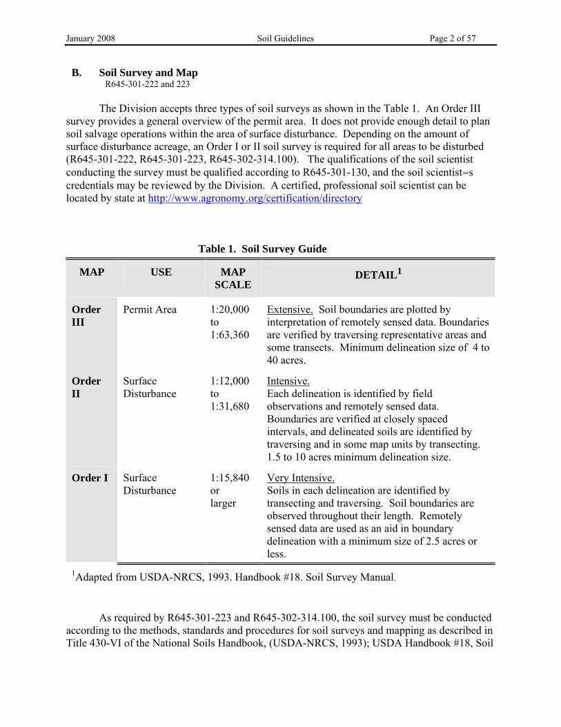
The Division accepts three types of soil surveys as shown in the Table 1. An Order III survey provides a general overview of the permit area. It does not provide enough detail to plan soil salvage operations within the area of surface disturbance. Depending on the amount of surface disturbance acreage, an Order I or II soil survey is required for all areas to be disturbed (R645-301-222, R645-301-223, R645-302-314.100). The qualifications of the soil scientist conducting the survey must be qualified according to R645-301-130, and the soil scientist=s credentials may be reviewed by the Division. A certified, professional soil scientist can be located by state at http://www.agronomy.org/certification/directory
Table 1. Soil Survey Guide
MAP
USE
MAP
SCALE
DETAIL1
Order III
Permit Area
1:20,000 to 1:63,360
Extensive. Soil boundaries are plotted by interpretation of remotely sensed data. Boundaries are verified by traversing representative areas and some transects. Minimum delineation size of 4 to 40 acres.
Order II
Surface Disturbance
1:12,000 to 1:31,680
Intensive. Each delineation is identified by field observations and remotely sensed data. Boundaries are verified at closely spaced intervals, and delineated soils are identified by traversing and in some map units by transecting. 1.5 to 10 acres minimum delineation size.
Order I
Surface Disturbance
1:15,840 or larger
Very Intensive. Soils in each delineation are identified by transecting and traversing. Soil boundaries are observed throughout their length. Remotely sensed data are used as an aid in boundary delineation with a minimum size of 2.5 acres or less.
1Adapted from USDA-NRCS, 1993. Handbook #18. Soil Survey Manual.
As required by R645-301-223 and R645-302-314.100, the soil survey must be conducted according to the methods, standards and procedures for soil surveys and mapping as described in Title 430-VI of the National Soils Handbook, (USDA-NRCS, 1993); USDA Handbook #18, Soil
January 2008 Soil Guidelines Page 3 of 57
Survey Manual (USDA-NRCS, 1993); and Keys to Soil Taxonomy, 8th ed. (Soil Survey Staff, 1998). The surveys will describe the topography, elevation, and climate characteristics of the site as well as the observed and potential plant community, plant productivity, and land use (R645-301-222 et seq). This provides background information to be used in formulating the soils management plan for operations and reclamation. Perform all soil surveys prior to ground disturbance (R645-301-211, R645-301-222, R645-301-232.600). Before initiating the Order I Soil Survey, consult the existing mine plan cultural and historic resource maps and/or contact the State History Preservation Office for information on historic sites within the soil survey area so that the soil survey is not destructive to these sites (R645-301-411.144). The Order I and II surveys contain information collected from soil pits and supplemental auger holes arranged on transects throughout the site. From the soil pits, a description of the soil profile is made. Sample each profile and provide analytical results from collected samples (R645-301-223 and R645-302-314.100). (Soil analysis procedures are discussed in the following section.) Use the information obtained during the survey to create a soils map of the site on a scale of 1:15,000 or larger (R645-301-222.100 and R645-302-314.100).
Within the Order I or II survey (R645-301-222.100 and R645-302-314.100): Provide a soil survey map at 1:15,000 (1 in = 1,250 ft) scale or larger (R645-301-141) with:
• Sample sites identified. • The extent of each soil type outlined. • Inclusions1 within the soil type which are either more limiting or
beneficial for reclamation shown. • The percentage area of inclusions within each soil map unit. • If the same scale (1:15,000) is used for the proposed surface
facilities map (R645-301-141 and R645-301-521.161), it can be easily overlaid onto the soil survey map for planning purposes. .
• Preparation of a soil salvage map, outlining each soil type, soil salvage area, salvage acreage and salvage depth can be used to help describe the methods for removing topsoil and subsoil (R645-301-231.100). In addition, a salvage map will enable field personnel to readily identify soil salvage areas without having to stop and read the soil survey in the Mining and Reclamation Plan.
C. Soil Characterization R645-301-222, 223, 224
1Inclusions: soils that are not described by the soil map unit name and that cannot be used for the same
purposes as the surrounding soils. They could be separately delineated if the map scale permits it. Areas too small to delineate may be identified and located on the map by special symbols.
January 2008 Soil Guidelines Page 4 of 57
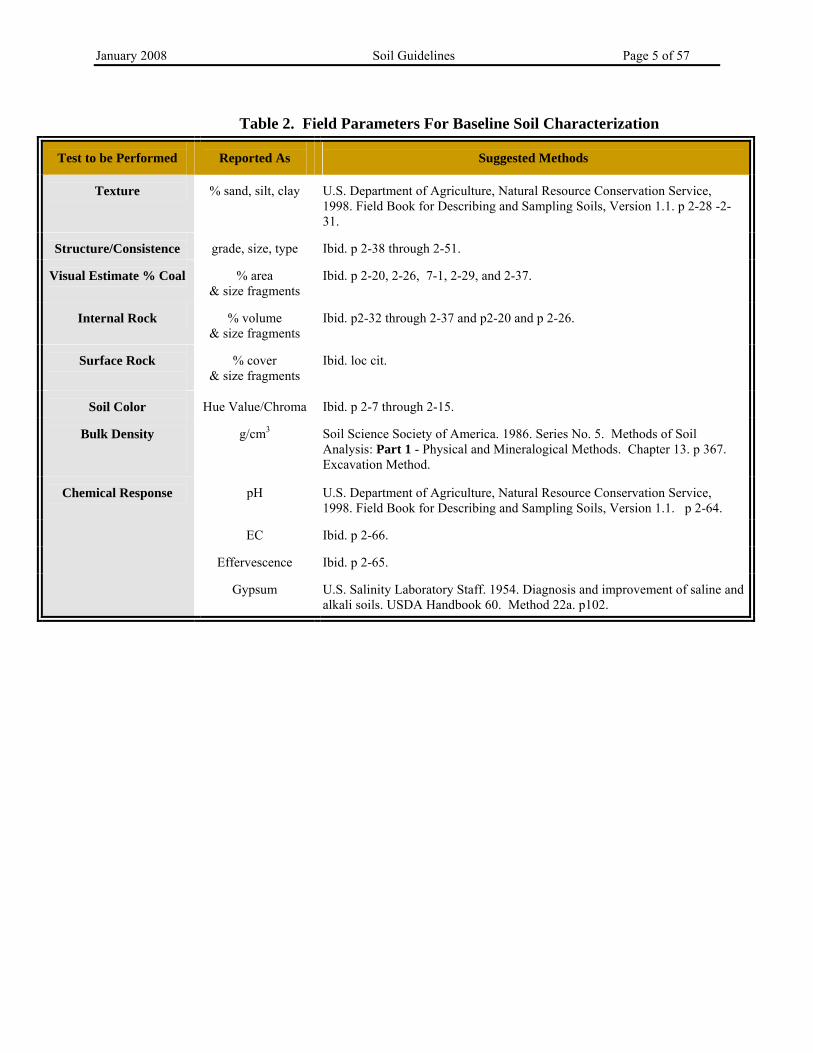
The procedures outlined in this section are taken directly from the National Cooperative Soil Survey which is incorporated in the R645 Rules by reference R645-301-223 and R645-301-314.100. Locate and evaluate each soil pit and/or auger location to thoroughly represent each mapping unit and to characterize the parent material, vegetative communities, slope and aspect. The number of sampling sites depends largely on the variability of the soils at the site and the extent of each soil map unit. At a minimum, represent each soil type with at least one soil pit location. Auger locations are used along transects from the soil pit to further delineate each soil type. Sample and report each inclusion separately. At the time of sampling, characterize each location for physical and chemical parameters according to Table 2 and following the protocol of the Field Book for Describing and Sampling Soils, USDA-NRCS, 1998. Sample by soil horizon and report the depth interval. Where no horizons are evident, sample every 6 inches (15 cm) or less for the first 12 inches (30 cm) of the soil profile and at 24-inch (60 cm) depth intervals thereafter, down to 72 inches (180 cm) or to bedrock, whichever comes first. Record the location and the depth for each individual soil sample. Conduct the laboratory analyses listed in Table 3 for each increment sampled. Encourage the laboratory to use the recommended methods to enable comparison between samples and locations. The field parameters along with laboratory analyses of pH, Saturation Percent, Electrical Conductivity, Sodium Adsorption Ratio, Particle Size Analysis, Available Water Capacity, K-factor, and %CaCO3 will be used to establish the soil type and evaluate the suitability of soil and overburden for salvage and use in reclamation (see Table 4). Replacement depths of topsoil may vary over the site with the objective of establishing a diverse plant population. However, Utah regulations specify that four feet of cover is required over any toxic or acid-forming materials (R645-301-528.350 and R645-301-553.250; R645-301-553.300 and R645-301-731.300 et seq).
January 2008 Soil Guidelines Page 5 of 57
Table 2. Field Parameters For Baseline Soil Characterization
Test to be Performed
Reported As
Suggested Methods
Texture
% sand, silt, clay
U.S. Department of Agriculture, Natural Resource Conservation Service, 1998. Field Book for Describing and Sampling Soils, Version 1.1. p 2-28 -2-31.
Structure/Consistence
grade, size, type
Ibid. p 2-38 through 2-51.
Visual Estimate % Coal
% area
& size fragments
Ibid. p 2-20, 2-26, 7-1, 2-29, and 2-37.
Internal Rock
% volume
& size fragments
Ibid. p2-32 through 2-37 and p2-20 and p 2-26.
Surface Rock
% cover
& size fragments
Ibid. loc cit.
Soil Color
Hue Value/Chroma
Ibid. p 2-7 through 2-15.
Bulk Density
g/cm3
Soil Science Society of America. 1986. Series No. 5. Methods of Soil Analysis: Part 1 - Physical and Mineralogical Methods. Chapter 13. p 367. Excavation Method.
pH
U.S. Department of Agriculture, Natural Resource Conservation Service, 1998. Field Book for Describing and Sampling Soils, Version 1.1. p 2-64.
EC
Ibid. p 2-66.
Effervescence
Ibid. p 2-65.
Chemical Response
Gypsum
U.S. Salinity Laboratory Staff. 1954. Diagnosis and improvement of saline and alkali soils. USDA Handbook 60. Method 22a. p102.
January 2008 Soil Guidelines Page 6 of 57
Table 3. Analytical Methods For Baseline Soil Characterization Test to be Performed
Reported As
Suggested Methods1
pH
saturated paste standard units
Soil Science Society of America. 1996. Series No. 5. Methods of Soil Analysis: Part 3 - Chemical Methods. Chapter 14, page 420 and Chapter 16, page 487.
Soil Science Society of America. 1996. Series No. 5. Methods of Soil Analysis: Part 3 - Chemical Methods. Chapter 38. p 1129 (KCl extraction). For analysis follow: Sims, J.R. and G.D. Jackson. 1971. Rapid Analysis of Soil Nitrate with Chromotropic Acid. Soil Sci. Soc. Am. Proc. 35-603-606.
Available Phosphorus
mg/Kg
Soil Science Society of America. 1996. Series No. 5. Methods of Soil Analysis: Part 3 - Chemical Methods. Chapter 32, page 895. (NaHCO3 Extraction.)
Particle Size Analysis
% very fine sand,
sand, silt, clay
Soil Science Society of America. 1986. Series No. 5. Methods of Soil Analysis: Part 1 - Physical and Mineralogical Methods. Chapter 15 pp 398 and 404-409 (Hydrometer Method).
Organic Matter
%
Western States Laboratory Proficiency Testing Program Soil and Plant Analytical Methods. 1998. v 4.10. p 86. (Loss on Ignition, convert %LOI to OM by regression intercept value as noted in method)
CaCO3 % % Ibid. p. 99 (Soil Carbonates, Gravimetric Determination after extraction with 3 M HCl.) Total Inorganic Carbon = %CaCO3 x 0.12.
Extractable Potassium meq/100 g-1 Western States Laboratory Proficiency Testing Program Soil and Plant Analytical Methods. 1998. v 4.10. p 73
1 Laboratories vary in their capabilities. Specify these recommended methods to the laboratory. Use of other methods should be discussed with the Division.
a For clay textured soils unacceptable is SAR >14. For sandy textured soils unacceptable is >20. b For most Western soils, the SAR to ESP relationship is usually 1:1, up to ESP . 20. If SAR>20, then determine ESP. (Evangelou, 2000.) c s=sand, l= loam, si= silt, c= clay, v= very, f= fine, co=coarse, g=gravel d Available Water Capacity is adjusted for texture and SAR. eK factor recommendations from the USDA Soil Conservation Service.1978. National Soils Handbook Notice 24. (3/31/78). NSH Part II B403.6(a). For Prime Farmland soils, the K factor times the percent slope should be a value of five or less for minimal erosion hazard.
January 2008 Soil Guidelines Page 8 of 57 1. Saturated Paste Methods To obtain a sample of the soil solution for salinity analyses, the laboratory will make a saturated paste. The least amount of water possible should be added to the soil sample to enable comparison between salinity measurement and actual soil conditions. Over dilution of the soil sample misrepresents field conditions, because the dissolution of salts is relative to the amount of water in the extract. The saturated paste method (Rhoades, 1996) is the preferred method for obtaining soil solution extracts. The saturated paste method (see Table 3) is preferable, but not always practical when clay soils are being analyzed. The soil:water ratio used for extraction should always be reported. The saturated paste extract is used for laboratory analysis and calculation of the following parameters:
a) pH b) Saturation Percent c) Electrical Conductivity d) Sodium Adsorption Ratio e) Exchangeable Sodium Percentage
a. pH The pH is the negative logarithm to base 10 of the hydrogen ion activity and therefore indicates the acidic or basic condition of the soil (pH of 7 is neutral; pH below 7 is acidic; pH above 7 is basic). The pH measurement is valuable as an indicator of the availability of plant nutrients and the presence of particular ions in the soil solution. For example, a pH of 8.3 or less indicates that calcium is abundant in the soil solution, whereas above pH 8.5, the sodium ion dominates the soil solution. Values of pH 5.0 to 5.5 could indicate soluble, toxic levels of Al3+ and Mn2+. Extreme conditions, such as pH below 3.0, indicate the presence of metal sulfides. In calcareous soils, the major factor determining pH is the carbonate to bicarbonate (CO3
∋ : HCO3!) ratio as affected by the partial pressure of carbon dioxide (Thomas, 1996). This
ratio also has importance in the evaluation of the sodium adsorption ratio (Ayers and Westcot, 1985). Standard methods for measuring soil pH include saturated paste or 1:1 (soil:water) extract. b. Saturation Percentage Saturation percent (SP) is commonly determined by drying a subsample of the saturated paste (Dudley, 2000). (A subsample is used, because oven-dried samples can not be used for further extraction and analysis, since heating converts gypsum to plaster of Paris and the latter salt has a higher solubility in water.) The weight of the subsample of saturated soil is recorded and then the soil is oven-dried. The oven-dry soil weight is recorded. The SP is calculated by
January 2008 Soil Guidelines Page 9 of 57 dividing the total weight of the water by the weight of the oven dry subsample and multiplying by 100 as follows ( USDA-NRCS, 1996): SP = 100 (weight of saturated soil weight of oven dry soil) oven dry soil weight An estimate of saturation percentage can be made using a Bureau of Soils cup of known geometry and volume. This method is described in the 1996 Soil Science Society of America, Methods of Soil Analysis, Part 3, pages 427 –429. c. Electrical Conductivity Soil salinity or the total concentration of soluble and readily dissolved salts such as Na+, Mg2+, Ca2+, K+, Cl!, SO4
2!, HCO3!, and CO3
2! in a soil is measured by the Electrical Conductivity of the saturated paste, EC (Table 3 lists the method.) Solubility increases with temperature, therefore all EC measurements are corrected to 25ΒC. The ionic strength of the soil solution may be approximated by multiplying the EC value in mmhos/cm times 0.014 (Evangelou,1998).
Excess soluble salts create a three-fold problem for plant growth:
1. The soil solution contains so much salt that the osmotic potential is very low and plant roots cannot draw water from the soil.
2. Excess sodium in the soil physically alters the clay lattice structure, reducing permeability of the soil. The excess sodium destroys the soil structure by dispersing the soil particles. Soil pore spaces are eliminated and the soil becomes impermeable. Infiltration and drainage of air and water are severely limited (and the erosion hazard increases). These effects are more pronounced in fine-textured soils than in coarse-textured soils.
3. Sodic soils are likely to have alkaline characteristics. The most common effect of an alkaline soil is reduced availability of nutrients to plants.
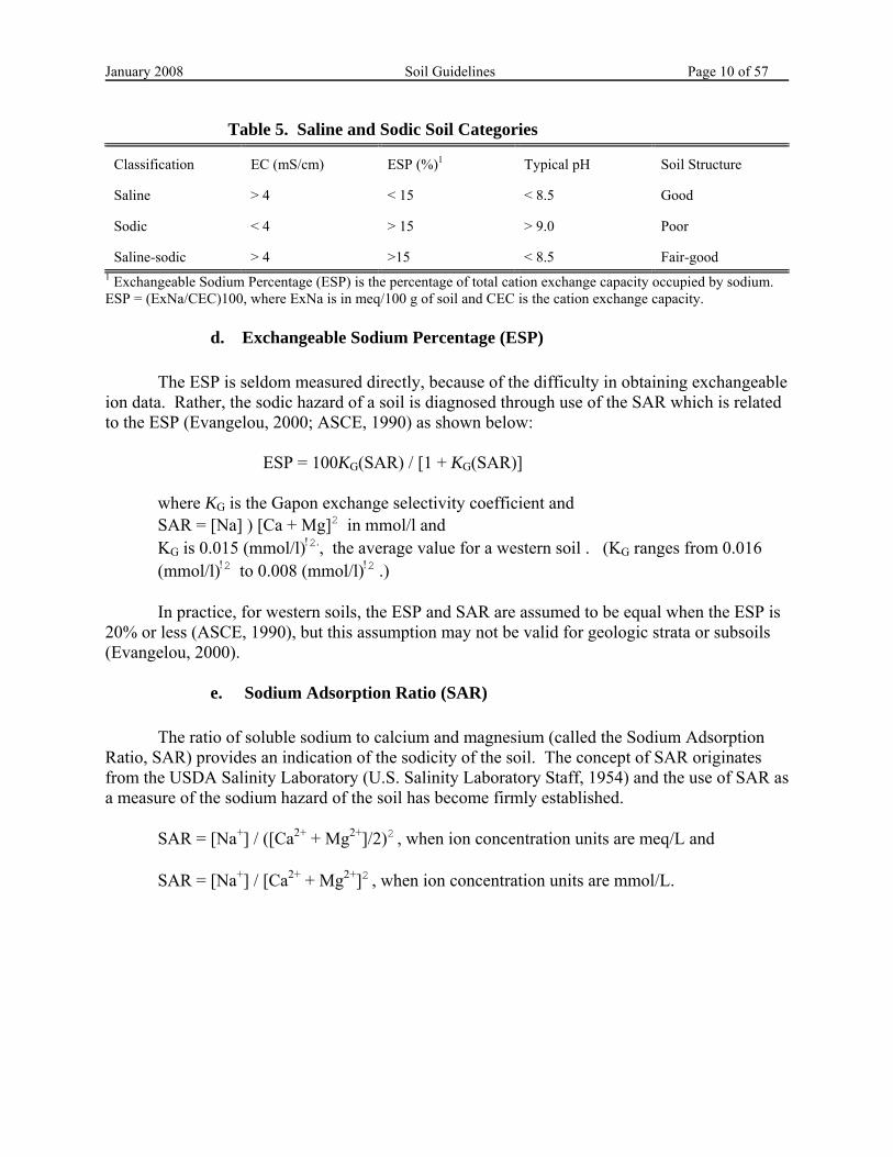
Using the parameters of electrical conductivity (EC), exchangeable sodium percentage (ESP), and pH, salt-affected soils have been classified as saline, sodic and saline-sodic, see Table 5 below. However, the sodium effect on a soil is strongly influenced by mineralogy, texture, organic matter content, and this classification must be adjusted accordingly (Dudley, 2000). For instance, soils with EC greater than 2.2 mmhos/cm and low Sodium Adsorption Ratio (SAR) values could signify the presence of excess gypsum, whereas soils with EC of 2.2 mmhos/cm and high SAR values could indicate excess NaHCO3. The latter situation is much more difficult to reclaim than the former (Evangelou, 2000).
January 2008 Soil Guidelines Page 10 of 57 Table 5. Saline and Sodic Soil Categories Classification
EC (mS/cm)
ESP (%)1
Typical pH
Soil Structure
Saline
> 4
< 15
< 8.5
Good
Sodic
< 4
> 15
> 9.0
Poor
Saline-sodic
> 4
>15
< 8.5
Fair-good
1 Exchangeable Sodium Percentage (ESP) is the percentage of total cation exchange capacity occupied by sodium. ESP = (ExNa/CEC)100, where ExNa is in meq/100 g of soil and CEC is the cation exchange capacity. d. Exchangeable Sodium Percentage (ESP) The ESP is seldom measured directly, because of the difficulty in obtaining exchangeable ion data. Rather, the sodic hazard of a soil is diagnosed through use of the SAR which is related to the ESP (Evangelou, 2000; ASCE, 1990) as shown below:
ESP = 100KG(SAR) / [1 + KG(SAR)]
where KG is the Gapon exchange selectivity coefficient and SAR = [Na] ) [Ca + Mg]2 in mmol/l and KG is 0.015 (mmol/l)!2., the average value for a western soil . (KG ranges from 0.016 (mmol/l)!2 to 0.008 (mmol/l)!2 .)
In practice, for western soils, the ESP and SAR are assumed to be equal when the ESP is 20% or less (ASCE, 1990), but this assumption may not be valid for geologic strata or subsoils (Evangelou, 2000). e. Sodium Adsorption Ratio (SAR) The ratio of soluble sodium to calcium and magnesium (called the Sodium Adsorption Ratio, SAR) provides an indication of the sodicity of the soil. The concept of SAR originates from the USDA Salinity Laboratory (U.S. Salinity Laboratory Staff, 1954) and the use of SAR as a measure of the sodium hazard of the soil has become firmly established.
SAR = [Na+] / ([Ca2+ + Mg2+]/2)2 , when ion concentration units are meq/L and
SAR = [Na+] / [Ca2+ + Mg2+]2 , when ion concentration units are mmol/L.
January 2008 Soil Guidelines Page 11 of 57
2. Available Water Capacity
An important characteristic of soil is the amount of water that is retained in the soil, readily available to plants. This available water capacity (AWC) is defined as the difference between the measurement of water content at field capacity (FC) and permanent wilting point (PWP), with corrections for salinity and rock fragments.
Available water holding capacity is affected by soil organic matter content, structure compaction and texture. In general, finer-textured soils have a greater water holding capacity than coarse textured soils because of the capillary pores which tightly hold water and smaller pore spaces that slowly drain water. In coarse-textured soils, increased rooting depth can compensate for a low value of available water capacity. But, where the combination of limited rainfall, shallow rooting zone and low available water content occurs, plant establishment and growth will be adversely affected.
Available water capacity can be estimated based on soil type and soil properties such as
particle size, soil pores, organic matter, clay type, soil structure, and coarse fragment content (Nyenhuis, 2001). A soil water calculator developed for estimating available water capacity can be found at www.bsyse.wsu.edu/saxton/soilwater based upon the work published in the Soil Science Society of America (Saxton et al., 1986). The web site will calculate the average values of available water holding capacity for various soil textural classes. These values may be used in-lieu of direct measurements. These estimated values should correlate with the laboratory’s reported value for “Saturation Percentage” for the soil.
Coarse fragments in the soil (gravel, cobble, and stone) occupy volume and therefore
reduce the amount of water held in the soil. However, the percent reduction in AWC is not equal to the volume occupied by the coarse fragments since the coarse fragments themselves retain some moisture. Use the following equation to estimate the percent reduction of AWC based on coarse fragment percent:
% AWC Reduction = 1.51[% coarse fragment]
Finally, AWC is reduced by salts in the soil solution. As a rough guide, reduce the AWC
by 25 percent for each 4 mmhos/cm EC of the saturated extract (USDA-NRCS, 1993). AWC can be measured directly using laboratory techniques (USDA-NRCS, 1996,
Method 4C). Due to limited water holding capacity, replaced topsoil/substitute topsoil materials may need amendments to improve the water-holding characteristics of the soil. Soil amendments include composted sewage sludge (bio-solids), wood chips, manures, and mulch. Incorporation of organic materials improves water infiltration, and reduces soil temperatures. Composted sludge and manures not only supply primary plant nutrients (nitrogen, phosphorus and potassium) but they are also excellent soil conditioners. The added organic material builds soil structure, restores soil tilth (makes the surface less hard), which improves the retention of water.
January 2008 Soil Guidelines Page 12 of 57
This helps to control erosion. Extreme surface roughening during reclamation grading is also extremely useful for helping to retain water. Further information on extreme surface roughening and organic matter additions can be found in this document in Section 4.B. Soil Stabilization and Erosion Prevention. 3. K Factor - Soil Erodibility The Revised Universal Soil Loss Equation (RUSLE) is discussed in Agriculture Handbook Number 703 (Renard, et.al. 1997). Or this information can be downloaded from: ftp://solar1.sedlab.olemiss.edu/pub/outgoing/RUSLE_Documentation/AH_703.pdf The soil erodibility factor (AK@) is a numeric representation of the ability of soils to resist erosion and susceptibility of soil particle detachment by water. If soils are undisturbed and county soil surveys are available, the K factors are published in the U.S. Department of Agriculture, Soil Conservation Service (SCS) reports for specific sites. For disturbed soils, substitute soils and unpublished soils, the soil erodibility (K) factor must be calculated from the following soil characteristics:
$ percent silt and very fine sand $ percent sand $ percent organic matter $ soil structure and $ soil permeability.
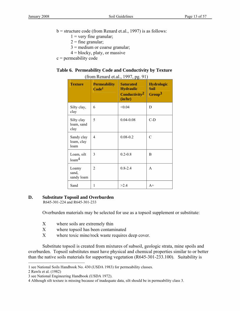
The percent very fine sand is the soil fraction that is retained by a 0.05 mm seive and passes through a 0.100 mm sieve. Procedures for percent organic matter, soil structure and texture (for the percent sand) are given in Table 3. The soil permeability is estimated from the soil=s texture using Table 6 which has been reprinted from Handbook 703 to illustrate the connection between texture and permeability code. An important consideration to be taken into account when assessing the soils permeability is the SAR value of the soil (Evangelou, 2000). High SAR values will lower the permeability of a soil and its resistance to erosion. This effect is reflected in the K factor by the permeability code and hydrologic group chosen from Table 6. The K factor can be derived using a nomograph located in Agriculture Handbook 703, Chapter 3, page 92 (Renard et.al., 1997). The same nomograph can be found in the National Soils Handbook Title 430 Part 618, Soil erodibility factors, USLE, RUSLE, exhibit 618.12. available on the internet at http://www.statlab.iastate.edu/soils/nssh The nomograph integrates the relationship between the K factor and the five soil properties listed above. The soil erodibility equation also provides an estimate of K, which can be calculated using the following equation and information from Table 6:
K factor = [(0.00021)(M1.14 )(12 - a) + (3.25)(b - 2) + (2.5)(c - 3)] / 100 Where M = (% silt + % very fine sand)(100 - % clay) a = % organic matter
January 2008 Soil Guidelines Page 13 of 57
b = structure code (from Renard et.al., 1997) is as follows: 1 = very fine granular; 2 = fine granular; 3 = medium or coarse granular; 4 = blocky, platy, or massive
c = permeability code Table 6. Permeability Code and Conductivity by Texture
(from Renard et.al., 1997, pg. 91) Texture
Permeability Code1
Saturated Hydraulic Conductivity2 (in/hr)
Hydrologic Soil Group3
Silty clay, clay
6
<0.04
D
Silty clay loam, sand clay
5
0.04-0.08
C-D
Sandy clay loam, clay loam
4
0.08-0.2
C
Loam, silt loam4
3
0.2-0.8
B
Loamy sand, sandy loam
2
0.8-2.4
A
Sand
1
>2.4
A+
D. Substitute Topsoil and Overburden R645-301-224 and R645-301-233
Overburden materials may be selected for use as a topsoil supplement or substitute:
Χ where soils are extremely thin Χ where topsoil has been contaminated Χ where toxic mine/rock waste requires deep cover.
Substitute topsoil is created from mixtures of subsoil, geologic strata, mine spoils and overburden. Topsoil substitutes must have physical and chemical properties similar to or better than the native soils materials for supporting vegetation (R645-301-233.100). Suitability is 1 see National Soils Handbook No. 430 (USDA 1983) for permeability classes. 2 Rawls et al. (1982) 3 see National Engineering Handbook (USDA 1972). 4 Although silt texture is missing because of inadequate data, silt should be in permeability class 3.
January 2008 Soil Guidelines Page 14 of 57
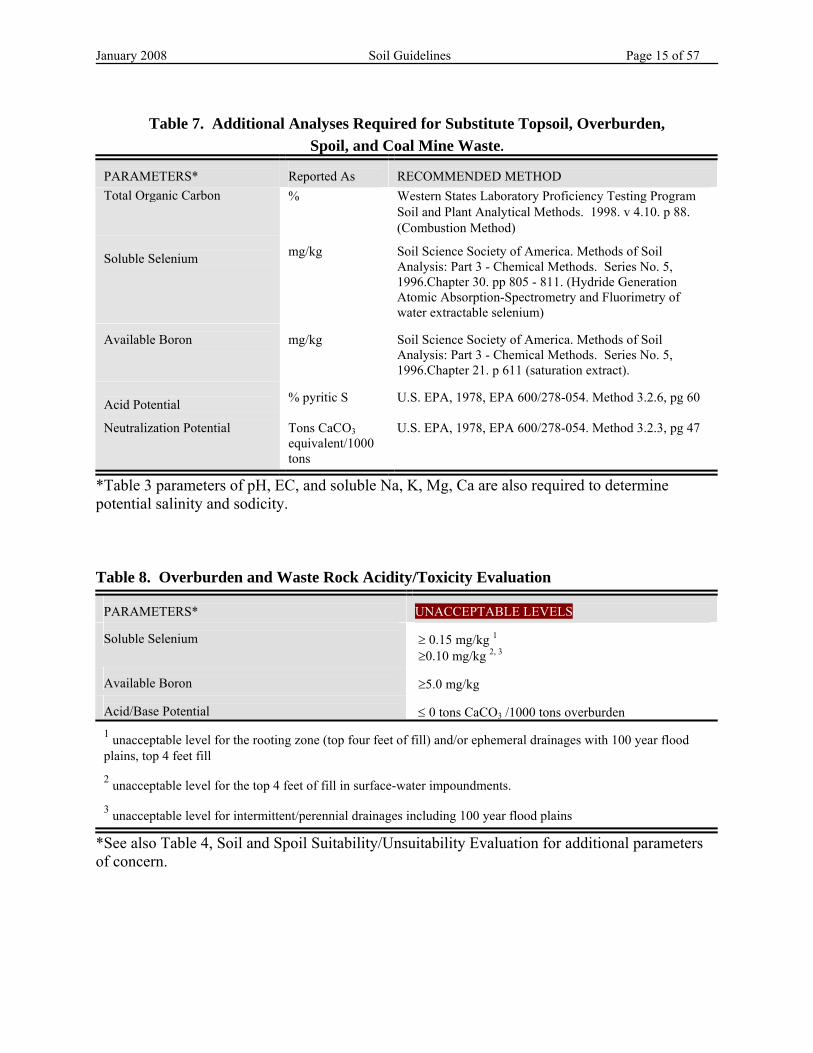
outlined in Tables 2 through 4. To evaluate suitability (R645-301-233.100) and to avoid surface placement of acid or toxic materials (R645-301-731.300 et seq and R645-301-553.250 and R645-301-553.300), substitute materials, overburden, sediment pond wastes, and rock waste must also be analyzed for acid and toxic forming characteristics listed in Table 7. Table 8 reports the acceptable values of the acidity and toxicity parameters outlined in Table 7. Finally, substitute materials proposed for use within the vegetative root zone must result in a soil medium that is the best available (R645-301-233.100). Include the analytical and physical results from sampling evaluations in the mine plan to demonstrate the suitability of the substitute material or to formulate a plan for the burial of toxic- and/or acid-forming overburden. The Division may require test plots to ensure the material is suitable if the characteristics of proposed substitute soils are in doubt. 1. Selenium Overburden rich in selenium may contaminate surface water and groundwater and may result in selenium toxicity to animals browsing on plants growing in selenium rich soils. Selenium is associated with sulfide minerals found in sedimentary deposits dominated by shales (mine spoil, waste rock, and mine-processing waste). Under alkaline conditions, insoluble selenium minerals are oxidized to soluble selenate (SeO4
2!) and selenite (SeO32!)
through natural weathering processes. These ions compete with other anions such as phosphate, sulfate, oxalate and molybdate for adsorption sites onto clays and oxides. AAdsorption is influenced positively by organic carbon, clay content, CaCO3, and cation-exchange capacity (CEC) and negatively by high salt, alkalinity, and pH,@ reports Mayland et al. 1990. Selenite is more strongly adsorbed than selenate, leaving the selenate more available for plant uptake (Mayland et. al. 1990).
January 2008 Soil Guidelines Page 15 of 57
Table 7. Additional Analyses Required for Substitute Topsoil, Overburden,
Spoil, and Coal Mine Waste. PARAMETERS*
Reported As
RECOMMENDED METHOD
Total Organic Carbon % Western States Laboratory Proficiency Testing Program Soil and Plant Analytical Methods. 1998. v 4.10. p 88. (Combustion Method)
Soluble Selenium
mg/kg
Soil Science Society of America. Methods of Soil Analysis: Part 3 - Chemical Methods. Series No. 5, 1996.Chapter 30. pp 805 - 811. (Hydride Generation Atomic Absorption-Spectrometry and Fluorimetry of water extractable selenium)
Available Boron
mg/kg
Soil Science Society of America. Methods of Soil Analysis: Part 3 - Chemical Methods. Series No. 5, 1996.Chapter 21. p 611 (saturation extract).
Acid Potential
% pyritic S
U.S. EPA, 1978, EPA 600/278-054. Method 3.2.6, pg 60
Neutralization Potential
Tons CaCO3 equivalent/1000 tons
U.S. EPA, 1978, EPA 600/278-054. Method 3.2.3, pg 47
*Table 3 parameters of pH, EC, and soluble Na, K, Mg, Ca are also required to determine potential salinity and sodicity. Table 8. Overburden and Waste Rock Acidity/Toxicity Evaluation
PARAMETERS*
UNACCEPTABLE LEVELS
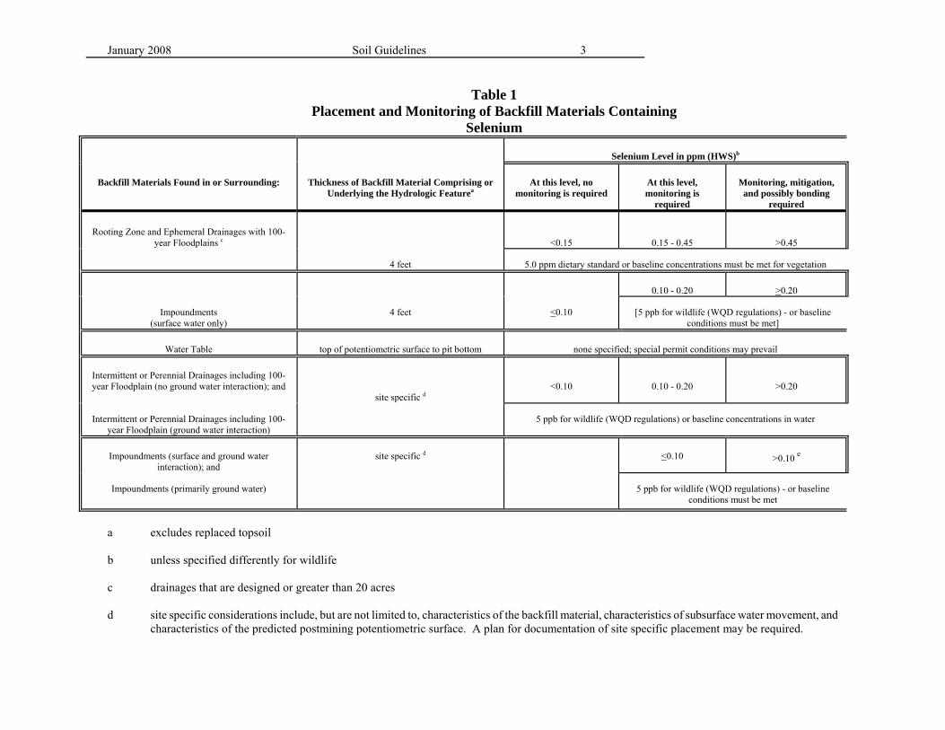
Soluble Selenium
≥ 0.15 mg/kg 1 ≥0.10 mg/kg 2, 3
Available Boron
≥5.0 mg/kg
Acid/Base Potential
≤ 0 tons CaCO3 /1000 tons overburden
1 unacceptable level for the rooting zone (top four feet of fill) and/or ephemeral drainages with 100 year flood plains, top 4 feet fill 2 unacceptable level for the top 4 feet of fill in surface-water impoundments. 3 unacceptable level for intermittent/perennial drainages including 100 year flood plains
*See also Table 4, Soil and Spoil Suitability/Unsuitability Evaluation for additional parameters of concern.
January 2008 Soil Guidelines Page 16 of 57
Selenium accumulates in surface soils by capillary action in regions where evaporation exceeds precipitation or by the decomposition of plants that have bio-accumulated high concentrations of selenium (Mayland, 1994). Plants accumulate selenium in their tissues to varying degrees. Plants that can accumulate several thousand parts per million (ppm) concentrations of Se include Astragalus, Machaeranthera, Haplopappus, and Stanleya. These species and are indicative of seleniferous soils (James et al, 1994). Non-accumulator plant species such as grasses, shrubs, small grains and alfalfa are most often the cause of selenium poisoning in livestock (James et al, 1994); yet they accumulate less than 50 ppm. Selenium in low levels is essential to animal nutrition. However, toxicity occurs when animals consume plants containing 3 to 20 ppm over a long period. Acute toxicity occurs when animals consume vegetation containing 100 ppm or greater (Fisher, et al,1987). If water soluble selenium exceeds values as outlined in Table 8 above, then placement, assessment, and monitoring of backfill materials containing selenium will follow the Joint Selenium Task Force Statement of Best Available Technology, June 1994 (Attachment 1). 2. Boron Boron is an essential micronutrient for plant growth and required in very small concentrations. Boron is quite mobile in soils concentrating in the surface of arid and semi-arid climates. Boron uptake by plants depends upon the activity of the B in soil solution which is a function of the clay content of the soil and soil pH as well as ionic strength, adsorbed ion composition and soil moisture content. The mechanism for boron retention by soil is adsorption on amorphous Al and Fe polymers, clays, organic matter and perhaps, carbonates (Dudley, 2000). Alkaline soils, mine waste, spoils, and coal of arid regions are suspect for elevated boron levels. These materials often contain high levels of sodium that form soluble sodium-borate salts. Low rainfall allows soluble borate salts to accumulate in the surface layer at concentrations toxic to plants. Boron can be responsible for reclamation failure in arid, alkaline locations. Boron toxicity to agricultural plants occurs when soils contain more than 5 ppm of hot-water-soluble boron. In boron rich areas, many native plant varieties are adapted to boron levels in excess of 5 ppm. Barth (1987) lists the reduction in yield of reclamation species due to boron content. Generally boron tolerance follows sodium tolerance. Soil and overburden containing more than 5 ppm soluble boron requires special handling. Although boron can be leached from the soil with water, this process would take about three times as much water as to leach sodium from the soil and would contribute to degradation of the receiving waters. Therefore, the best approach to dealing with elevated boron concentrations is to selectively bury the material. There is little concern of boron transfer from plants to animals (Barth et al, 1987).
January 2008 Soil Guidelines Page 17 of 57
3. Acid-Base Potential Acid formation occurs when sulfide-bearing minerals such as pyrite (FeS2), sphalerite (ZnS), and chalcopyrite (CuFeS2) are exposed to air and water. In the process of acid formation, sulfur products and metals are released into solution. The bacteria Thiobacillus ferrooxidans is the biological catalyst in the oxidation reaction. Results of acid formation include:
$ Lowers soil pH $ Increases trace metals (Fe, Al, Mn) to toxic levels, resulting in competition for
soil exchange sites with Na+, K+, Ca2+, Mg2+, and NH4+.
$ Binds nutrients, such as P with Fe and Al $ Increases ratios of H+ to Ca2+ and Mg2+, resulting in destruction of roots $ Inhibits nitrification, like the microbial conversion of NH4
+ to NO3-
$ Increases salinity or electrical conductivity (EC) Calcium carbonate materials neutralize the acidity formed by metal sulfide oxidation. Where iron-sulfide minerals in coal are overlain by calcareous rock, the mine drainage is neutral rather than acidic (Cravotta et.al., 1990; Skousen and Larew, 1991). For this reason, the acid base potential must be quantified for all underground development waste and overburden materials. Acid-base accounting is based on total-, sulfate- and sulfide-sulfur, bulk neutralization carbonate content, and pH. The acid base potential is determined by calculating the difference between the neutralizing potential (NP) and the total non-sulfate sulfur acid potential (AP) of the sample. (The method is referenced in Table 7.) The acidity is reported as % S and the carbonate content as % CaCO3. The %S and % CaCO3 must first be converted to tons CaCO3/1,000 tons overburden material.
To demonstrate that all coal and/or acid-forming material is disposed of in a manner that will prevent environmental degradation, the acid/base accounting must be integrated into the mine plan (R645-301-528 and R645-301-528.350 and R645-301-537.210 and R645-301-624.200 et seq and R645-301-624.300 et seq and R645-301-731.120 et seq and R645-301-731.300 et seq). Using the analysis, the mining and reclamation plan must describe the handling of acid-forming material (R645-301-731.120 et seq and R645-301-731.300 et seq). When amendments are deemed necessary to control acid production, calculations for the amount of lime or calcium carbonate to be mixed with the acid-forming material must be provided to ensure neutralization (R645-301-731.122 and R645-301-731.300).
January 2008 Soil Guidelines Page 18 of 57
Where calcareous overburden is lacking, the acid-forming materials can be amended with imported alkaline materials such as limestone (CaCO3) and lime [Ca(OH)2], blast furnace slag (CaSiO3), fly ash, and cement kiln dust (CaO). The amount of calcium carbonate to apply is calculated based upon the total sulfur and calcium carbonate content of the waste (Sobek, et.al. 1978; Cravotta, et.al 1990; Skousen 1991). The effectiveness of limestone as calcite (CaCO3) or dolomite (CaMg(CO3)2) is based on particle size and purity. Therefore, the larger the particle, the lower the effectiveness. The rest of the alkaline substances are generally very reactive and uniform incorporation into the spoil increases their effectiveness (Evangelou, 2000). To help prevent or minimize acid formation, keep the exposure of acid-producing material to a minimum. Treat and bury the waste immediately beneath four feet of the best available, non-toxic/acid forming material (R645-301-553.250 and R645-301-731.122 and R645-301-731.320). Grade the surface to promote runoff rather than infiltration, balancing the need to eliminate water and oxygen transport into the spoil with the need to establish vegetation. Burial of the acid forming materials under four feet of non-acidic or non-toxic material will reduce oxygen penetration to the pyritic spoil and diminish the acid production. Deeper burial of acid forming material will further reduce oxygen penetration. The non-toxic cover material will form the root zone. Cover material may be topsoil or spoil capped with topsoil. To avoid degradation of the topsoil by the upward migration of acidic salts, place a capillary barrier between the acid-forming waste and the rooting zone. A capillary barrier is formed of multiple soil layers with differing conductivity characteristics, which limit the movement of water into the acidic material (Society for Mining, Metallurgy, and Exploration, Inc (SMME), 1998). For instance, placement of coarse layer (high hydraulic conductivity) then fine layer (low hydraulic conductivity) then coarse material over acid generating waste, will trap moisture in the fine layer. Examples of some materials with low hydraulic conductivity are compacted clay, and fine-grained non-sulfidic mine tailings (SMME, 1998). Organic matter amendments generally help delay pyrite oxidation by consuming oxygen during decomposition. Organic matter reacts favorably with metals, creating complex associations. Organic matter removes iron, aluminum and other metals by adsorption and complexation (Sobolewski, 1997) and has been used in Anoxic Limestone Drains (Skousen 1991). Finally, sodium laurel sulfate, an anionic surfactant, may be applied directly to pyritic material to destroy Thiobacillus ferrooxidans: Kleinmann and Erickson, 1983, provide a detailed summary of application procedures and other considerations of the method. 4. Organic Carbon Content Overburden and disturbed soil proposed for use as substitute topsoil will be analyzed for organic carbon to determine the percentage of coal in the material. Organic carbon content is determined by the difference between total carbon measured by combustion (Table 8) minus the inorganic carbon (or soil carbonates) measured by loss on ignition (Western States Laboratory Proficiency Testing Program Soil and Plant Analytical Methods, 1998). Inorganic carbon (soil carbonates) are reported as %Loss on Ignition (%LOI). The %LOI is converted to Total Organic
January 2008 Soil Guidelines Page 19 of 57
Carbon after multiplying by 0.12. Total Organic Carbon content in proposed substitute topsoil will be limited to <10% weight (Table 7). Total organic carbon can approximate soil organic matter content after multiplication with a conversion factor, usually 1.724. The conversion factor may range from 1.6 to 2.5 depending upon soil type. The Division staff will conduct visual estimates of coal on the regraded surface (Table 2). Visual estimates should be less than 10% coal for pre-SMCRA sites utilized post- SMCRA by mining operations. No surface coal is acceptable on post-law site (R645-301-528.320 and R645-301-528.340 and R645-301-528.350 and R645-301-542.730 and R645-301-536). 3. OPERATION PLAN
R645-301-230
A. Soil Salvage Volume Calculations R645-301-232.100, -232.200, -232.300, & -232.500 Prior planning of salvage operations and on-site supervision of the salvage by a qualified soil scientist (R645-301-132) will assure the identification and surface placement of useful substitute topsoil materials during backfilling and grading, leaving the less desirable materials buried in the fill. In the Mining and Reclamation Plan, report estimates of the volume of soil to be salvaged. The topsoil balance sheet, Table 9, can be utilized throughout the life of the project to keep a running total of available soils versus disturbed acreage for the purpose of ensuring that adequate soil is available for reclamation. B. Soil Removal and Salvage Operations R645-301-231.100, -232.200, & -232.300 Use data generated during soil sampling, mapping, and analysis to prepare a topsoil salvage isopach map. The lines of equal thickness on the isopach map function as a practical field guide to soil removal. The isopach salvage map should show salvage areas by soil type and salvage depth for each soil type/area. Islands of vegetation diversity are desirable, particularly in large disturbance areas (greater than 30 acres). Salvaging native soils (which are typically rocky or bouldery) encourages the desired diversity in plant communities and allows the site to blend with the surrounding, undisturbed areas. Soils should be salvaged containing the natural, intrinsic amount of rock. Rock fragments are not considered harmful. Rock fragments should be angular and widely ranging in size. Used in moderation, rock increases depth of soil water absorption, reduces evaporation, moderates soil temperature, provides habitat diversity and helps reduce surface soil erosion. However, extremely rocky soils will limit water penetration and increase the value of the K factor (see Soil Surface Stabilization section). For these reasons, the Division does not encourage any artificial increase or decrease the amount of rock above or below the
January 2008 Soil Guidelines Page 20 of 57
natural, intrinsic rock content in the landscape.
To remove soil in a controlled manner the following methods are employed:
1. Pedestals (small islands of topsoil left to verify soil removal depth); 2. Pits (trenches dug with a backhoe to confirm soil removal depth); 3. A qualified soil scientist (providing on-site supervision); and 4. An experienced contractor.
Plan access to salvage areas in advance to minimize the area of disturbance and reduce soil handling. Give adequate forethought to the location of the topsoil storage area for the same reasons. Provide on-site supervision during the soil salvage operation for soil identification and stripping control. Use dust control measures during topsoil stripping activities; stop activity if dust is inadequately controlled. Segregate the topsoil (A horizon, R645-301-232.100, or both A and lower horizons where the A horizon is less than six inches, R645-301-232.300, or A, B, and C horizons, R645-301-232.500) from the underlying subsoils during salvage and storage. If necessary, during reclamation, horizons may be replaced in the reverse order of stripping so that the native soil profile is duplicated (R645-301-232.500). This effort will result in higher productivity of the reclaimed site. Soil aggregate structure is impacted by handling, compaction and moisture. Impacts to aggregate structure can be reduced by reducing the amount of vehicle traffic and minimizing the number times the soil is moved. To preserve the aggregate structure, soil salvage operations should only take place when soils are neither too wet nor too dry. During stripping and handling, soils should be in a loose or friable condition. Loose consistence refers to non-coherent, coarse-textured soils. Friable consistence refers to fine-textured soils that crumble readily when crushed.
These two rules should always be followed to prevent excess compaction (R645-301-242.120 and to prevent wind and water erosion of pulverized soil (R645-301-242.130):
Χ If the soil sticks to the equipment, wait until the soil has dried to a friable state. Χ If the soil is too dry and hard to handle, add water until the soil is wetted to a
loose and friable condition. C. Topsoil Stockpiles R645-301-234 Once stockpiled, do not re-disturb the soil until final reclamation (unless prior approval is received from the Division, R645-301-234.240). Wide, shallow soil stockpiles crossed as little as possible by earthmoving equipment will be the least compacted and will retain more micro-flora, bacteria, earthworms and viable seeds for plant reestablishment. Incorporate plant materials on the surface with the topsoil into the topsoil piles, including grasses, shrubs, and chipped woody materials.
January 2008 Soil Guidelines Page 21 of 57
The stored topsoil must (R645-301-234.200 and R645-301-521.270): • remain in place for the duration of mining. • not be subject to water or wind blown contaminant • not be subject to compaction. • have an identification sign to avoid accidental disturbance.
Provide a map showing the location of all topsoil stockpiles in relation to operational facilities (R645-301-521.165). The soil stockpile should be placed in a manner that:
In addition, the stockpile must be (R645-301-234.220 and R645-301-234.230):
• isolated to minimize contamination from mine related dusts. • seeded promptly because plants and their residue control wind and water
erosion, and maintain microbial activity.
Short term piles should be (R645-301-234.230): • seeded with a mix of quickly established grasses and grains which can be
tilled under as a green manure soil amendment. • seeded with an interim seed mix of grasses, forbs and shrubs, if the pile is to
remain in place longer than one year.
Include in the topsoil storage plan the designs for (R645-301-231.400):
1. drainage diversions 2. earthen berms 3. topsoil stockpile dimensions (include maximum slope and volume).
Discuss in the topsoil storage plan (R645-301-231.400 and R645-301-234.220 and R645-
301-234.230) the use of:
1. biological stabilization (include seeding rate and mixture). Native leguminous vegetation or other known nitrogen fixing species, are recommended to enhance soil fertility. The seed mixture should complement post-mine reclamation seed mix. Refer to revegetation guidelines.
2. mulch (type and rate). 3. addition of organic matter to alleviate soil compaction, maintain soil moisture,
and restore soil structure. 4. amendments (fertilizer or other). 5. surface roughening (gouging). 6. compaction mitigation. 7. weed control.
January 2008 Soil Guidelines Page 22 of 57
4. RECLAMATION PLAN
R645-301-240 A. Redistribution and Grading of Overburden and Topsoil R645-301-241, -242, -242.110, -242-120, and -242.200 In the grading plan (R645-301-521.141 and R645-301-553.100 et seq), compare pre-mining and proposed postmining surfaces on topography maps, with contour intervals of an equivalent scale. Areas of variation between pre and post mining topography maps should be investigated for erosion potential. To assess the change in slope between pre-mining and post-mining contours, sample locations should be marked on maps (a grid pattern with approximately 400' between sample locations is recommended). For each sample location, the minimum and maximum slopes, the means and the percentage of each slope class for both premining and postmining surfaces should be listed as well as cross sections (scale 1" = 200'- 400' horizontal, 1" = 10' vertical) of the pre and post mining landscape in the grading plan. The number and spacing of cross-sections will be site dependent.
Include in the plan a discussion of the following:
1. Timing for backfilling and grading; 2. Soil redistribution depths; 3. Soil redistribution plan:
a) specify the equipment that will be used, b) ripping of overburden to relieve compaction and ensure overburden/soil
contact, c) soil sampling program after redistribution;
4. Identify hazardous steep slopes; 5. Slope evaluations for pre- and post-mining surfaces; 6. Accounting of overburden in a mass balance table (see Table 10); 7. Timing of revegetation; 8. Seed-bed preparation plans (include fertilization, if any).
Establish the final grade in an area, complete all channel and riprap placement, and wildlife enhancements (rock piles) according to the reclamation plan and prior to topsoil replacement and seeding (645-301-251), Provide a map showing the extent of each topsoil redistribution depth when redistribution will not be uniform over the disturbed area (R645-301-241 and R645-301-242.110). Avoid compaction, work when the soil is in a loose or friable condition (R645-301-242.120, see Soil Removal and Salvage Operation, section III.B, page 22 of this guideline).
January 2008 Soil Guidelines Page 23 of 57
Table 9. Topsoil Balance Sheet
Area 1
Area 2
Area 3
TOTAL
Acres (ac)
Depth of Topsoil Removal (ft)
Estimate of Salvageable
Topsoil (yds3)
(area X depth =volume)*
Volume Actually
Salvaged (yds3)
Storage Location and
Capacity (yds3)
Depth of Proposed
Topsoil Replacement
Volume Required for Reclamation (yds3)
Surplus or Deficit
Volume (yds3)
*27 Cubic Feet (ft3) = 1 Cubic Yard (yds3)
1 Acre = 43,560 ft2 B. Soil Stabilization and Erosion Prevention
R645-301-244 All final surface and seedbed preparation should result in a roughened soil surface (R645-301-242.130 and R645-301-242.200). In Utah, surface roughening is the key factor in reclamation success for vegetation establishment, surface stabilization, and erosion control. Soils must be in a friable condition before implementing soil surface preparation techniques. When fertilizer is required, apply it before roughening the surface (R645-301-243). An excellent discussion of this topic can be found in The Practical Guide to Reclamation, available on the internet at http://dogm.nr.state.ut.us/mining/ Extreme surface roughening intercepts and traps sediment on a micro-scale. A trackhoe shovel creates basins with a depth of eighteen inches. Commonly, the method is to dig a bucket load of soil and then drop it adjacent to the hole. Repeating this process in a random and overlapping pattern makes it impossible for water to flow down slope. Finished roughened soils should be difficult to walk over. The size and distribution of pocks will vary with soil type, slope length and angle, etc. For instance, on Mancos shale sites, the pocks fill with sediment within a short time period.
January 2008 Soil Guidelines Page 24 of 57
Therefore, the pocks should be as large as possible on these soils. Yet large pocks in high moisture zones, may retain too much moisture. Consequently, depth of pocking should be evaluated for each site. Hay may be spread before roughening and anchored to the soil surface during the roughening process or straw may be applied to the roughened/seeded surface and tacked down with a hydromulch/tackifier slurry (R645-301-244.200).
Minimize the time between topsoil redistribution and revegetation (R645-301-244 and R645-301-354), to allow seed/soil contact before soil crusting occurs. The best practice is to seed immediately following topsoil application, before the soil crusts. A drill seeder cannot be used on rough surfaces, therefore broadcast seed by hand or hydroseed. In areas where the soils are extremely dry and loose, either wait until the soil has settled in the basin prior to seeding or broadcast half the seed immediately and the other half after settling.
January 2008 Soil Guidelines Page 25 of 57
Ripping is used as a soil roughening technique in areas too extensive to economically roughen by gouging with a backhoe (R645-301-242.200). Ripping breaks compacted layers of soil. Rip compact soil when it is relatively dry to permit shattering beneath the surface. The equipment travels along the contour of the slope, ripping to a depth of two feet (or more). The distance between rippers should be equal to the depth ripped. The ripper is lifted from the soil every 10 to 20 feet to reduce the chance of creating long water pathways subject to catastrophic breaching. Soil amendments or surface mulch may be incorporated into the soil during the ripping operation. Seed can be spread simultaneously with the ripping operation if a broadcast seeder is attached to the rear end of the ripping equipment. The Revised Universal Soil Loss Equation (RUSLE) equation illustrates the parameters which should be considered when planning for stabilization of disturbed sites (Renard, et al. 1997). Due to a limited database, the use of RUSLE in the Rocky Mountain region may require substantial local research with regard to meteorological records and soil information before it can be applied to disturbed, mountainous land.
The RUSLE equation is as follows:
A = R K L S C P, where
A = average annual erosion on field slopes in Ton/acre/yr
R = average annual total of storm energy by intensity (based on the 22-year average), called the rainfall erosivity factor (effects of snowmelt should be considered as well)
K = soil erodibility factor which is measured or estimated for each soil and based upon particle size (extremely rocky soils limit water penetration and increase the value of this factor)
L = a ratio of soil loss from a field slope to loss from controlled conditions, called the slope length factor
S = the ratio of soil loss to that under controlled conditions, called the slope steepness factor
C = a ratio of soil loss from an area with specified management to an area in continuous fallow, called the cover management factor (surface rock will lower this factor)
P = a ratio of soil loss with practices like gouging to soil loss with straight row farming up and down the slope, called the support practice factor
What the RUSLE model points out is length of slope and steepness of slope combined with the type of soil and rainfall (and/or snowmelt) all figure in the annual soil loss to be expected at a particular site. This loss can be reduced by applying favorable cover (mulch, rocks, shrub debris) and through management practices (roughening, eliminating compaction by ripping) and by limiting the exposure of disturbed land during periods of intense rainfalls and
January 2008 Soil Guidelines Page 26 of 57
snowmelt. Mulch is a protective layer. It can be organic (plant material) or inorganic (rock). Straw, hay and wood fiber mulch temporarily stabilize the surface and prevent erosion. They are effective for two to five years and then decompose. Rock is a permanent surface soil stabilizer. Consider using rock when the established vegetation does not control erosion. Rock stabilizes the soil surface and reduces evaporation. Rock is recommended for arid sites where 40% vegetative cover or less is expected. Rock as surface mulch mimics the desert pavement or rock veneer found occurring naturally in Utah deserts. Slash refers to the plant material salvaged prior to disturbance. These are dead shrubs, brush, trees, and tree and shrub parts. The large slash mulch helps:
$ reduce water and wind erosion $ provide protection from large herbivores and $ trap seed and fine soils on the reclaimed area.
Unlike hay or straw mulches, slash does not introduce competitive weed seeds. Also hay and straw mulch concentrate moisture at the soil surface, perhaps encouraging germination when conditions are otherwise unfavorable. Slash does not. Erosion control, matting or blankets, are used on slopes steeper than 22 horizontal to 1 vertical (2.5:1 or less than 44%) or areas where maximum soil surface stabilization is desired (i.e. adjacent to waterways). Employ other soil stabilization techniques when the topsoil will not be seeded within one month (see discussion above under Stockpiling Topsoil, also reference R645-301-244.200).
Table 10. Mulch Type Mulch Type
Application Rate
Method of Application
Anchoring Method
Notes
Grass Hay (native hay = ideal)
1 to 2 tons/acre
Blower, hand
Crimping, Chemical Binder, Netting
Certified Noxious Weed Free
Straw
1 ton/acre
Blower, hand
Crimping, Chemical binder, Netting
Certified Noxious Weed Free
Alfalfa hay
1 to 2 tons/acre
Blower, hand
Incorporated into soil surface
Certified Noxious Weed Free, Pulverizes in blower, better C:N ratio
Erosion Control Matting
entire area
Hand per Manufactures
Staples, Surveying stakes, trench top of
Lay loosely, snake mortality, breaks
January 2008 Soil Guidelines Page 27 of 57
Specification matting down in sunlight Wood Fiber Hydromulch
2 to 1 ton/acre
Hydromulcher
Chemical binder @ 80 to 120 lbs./acre or manufactures rate
C. Soil Nutrients and Amendments
R645-301-243 Replaced topsoil/substitute topsoil materials may need amendments, both to increase the supply of nutrients and to improve the physical, chemical and water-holding characteristics of the soils (R645-301-243). Determining whether nutrients are required (R645-301-241) may require sampling topsoil or substitute topsoil as it is replaced on the site. Samples should be analyzed for the plant available forms of nitrogen (N), phosphorus (P), and potassium (K). Plant available phosphorus should be determined by Extraction with Buffered Alkaline Solution (see Table 3).1 Productivity of a reclamation site is dependent upon
• the accumulation of organic matter and nitrogen; • the maintenance of nitrogen fixing legumes in the community; • and the establishment of an organic phosphorus pool.
All of these are dependent upon the introduction and function of microbial communities over time (Daniels and Zipper, 1999). Initial fertilizer applications of nitrogen are not recommended, because of weed competition. The Division has observed that the use of fertilizer generally promotes a flush of weed growth to the detriment of the native species. In the healthy reclaimed community, legumes will provide nitrogen through N-fixation and mycorrhizae will invade the plant roots helping to absorb phosphorus organically bound in the soil.
1Bray=s Extraction with Dilute Acid Fluoride should not be used in calcareous soils
(Dudley, 2000).
Phosphorus is the least available and consequently the most limiting nutrient for plant growth. As soils oxidize, phosphorus becomes fixed by iron oxides into unavailable forms. Phosphorus in the soil solution is replenished slowly. Phosphorus buffering capacity is soil specific. Soils with higher clay contents will have a greater capacity to replenish the soil solution P than coarse textured soils (Kuo, 1996). Organically bound phosphorus is not subject to fixation, so it is imperative that a pool of organic phosphorus in the soil becomes sustainable. Fertilize only after testing detects a major soil deficiency. And then, only use slow release or chelated fertilizers. Specify to the soils laboratory that their recommendations for fertilizer application rates should be based on dry land, native plant production, not agricultural production rates.
January 2008 Soil Guidelines Page 28 of 57 Solid fertilizer salts are broadcasted and liquid-based fertilizers are sprayed on the soil surface. Incorporate the fertilizer into the rooting zone by surface roughening, otherwise the nitrogen is lost to the atmosphere1 and phosphorus fertilizer will be fixed in the very top few centimeters of the soil where roots can not take advantage of the phosphorus source. In alkaline soils, although calcium compounds will precipitate phosphorus additions, much of the phosphorus remains available to plant roots if they can contact the particles of fixed phosphorus.2 Therefore incorporation of the fertilizer into the root zone is imperative. Soil amendments include chemical fertilizers, composted sewage sludge (biosolids), manures, and chipped wood byproducts. Incorporation of chipped wood by-products, straw or hay mulch improves water infiltration, and reduces soil temperatures. Composted sludge and manures not only supply primary plant nutrients (nitrogen, phosphorus and potassium), but also are excellent soil conditioners. The added organic material restores soil tilth and microbial populations that in turn increase availability of plant nutrients, especially nitrogen and phosphorus. As with other organic matter additions, the use of composted sewage sludge (biosolids) builds soil structure and makes the surface less hard, which improves the retention of water. These factors help to control erosion.
Why use biosolids rather than another organic matter addition?
$ Biosolids build microbial populations and biological activity in sites which have a deficit of topsoil (i.e., mine tailings, waste rock site, and overburden).
$ Biosolids act as a slow release fertilizer, providing available nitrogen over a five
year period. This slow release makes nitrogen not as available to quick growing annual weedy plants.
$ Biosolids mixed with fine material such as fly ash or tailings create friability and
permeability and improves wetting and drying characteristics of the tailings.
$ Biosolids application may be economically more feasible than using borrowed topsoil material.
2The fixation is compounded when large quantities of aluminum and iron or manganese are available (Evangelou, 2000).
$ Biosolids application may lower the pH by about one unit (i.e.10 times more
January 2008 Soil Guidelines Page 29 of 57
hydrogen activity within the soil solution). Requirements for land applications biosolids are established by the Code of Federal Regulations (CFR) and the Utah Annotated Code (UAC). The Utah Division of Environmental Quality (DEQ) is the permitting authority under UAC R317-8. The treatment plant operator is responsible for obtaining a permit and notifying DEQ when biosolids are land applied. The mine operator does not bear this permitting responsibility. Biosolids are applied at agronomic rates unless otherwise authorized by DEQ. Up to five times the agronomic rate may be authorized for a one-time application. (Schmitz, 1999). Agronomic rates are based upon the nitrogen requirement of the plant species to be grown. For example, the nitrogen requirements of some grasses used in reclamation have been determined to be 300 lbs/acre for fescue and 275 lbs/acre for perennial ryegrass (Phillips, 1996). This information along with the plant available nitrogen in the biosolids (ammonium, nitrate, nitrite, and mineralizeable organic nitrogen) is necessary to evaluate the agronomic rate.
Agronomic Rate in Tons biosolids / acre = crop N requirement ) kg avail N / Ton biosolids
January 2008 Soil Guidelines Page 30 of 57 LITERATURE CITED Ayers, R.S. and D. W. Westcott, 1985. Water Quality for Agriculture. Food and Agriculture Organization Irrigation Drainage Paper 29, pp 59-64. Barth R.C., R.C. Severson and G. Weiler. 1987. Boron, Chapter 7. In. Reclaiming Mine Soils and Overburden in the Western United States, Analytical Parameters and Procedures. R. Dean Williams and Gerald E. Schuman, (Eds.)Soil Conservation Society of America. p 146. Bohn, H.L.; B.L. McNeal; G.A. O=Connor. 1979. Soil Chemistry. (Wiley & Sons : N. Y.) p 226. Cravotta, C.A., K.B.C. Brady, M.W. Smith, and R.L. Beam. 1990. Effectiveness of the Addition of Alkaline Materials at Surface Coal Mines in Preventing or Abating Acid Mine Drainage: Part 1. Geochemical Considerations. In. Mining and Reclamation Conference and Exhibition, Charleston, West Virginia. Dudley, Lynn. 2000. personal communication with Dr. Lynn Dudley, Professor of Soil Chemistry, Utah State University, Department of Plants, Soils and Biometeorology, Utah State University, Logan UT 84322-48220. Evangelou, V. P. 2000. personal communication with Dr. Evangeou of Iowa State University, Agronomy Hall, Ames, IA 50011-1010. Evangelou, V. P. 2000. Soil Geochemistry for Arid and Semiarid Environments. Office of Surface Mining/Office of Technology Transfer. August 7, 2000. Evangelou, V.P. 1998. Environmental Soil and Water Chemistry Principles and Applications. John Wiley & Sons, Inc.: NY. p550. Fisher, Scott E, Jr., F.F. Munshower and F. Paraday, 1987. Selenium.. In. R. Dean Reclaiming Mine Soils and Overburden in the Western United States, Analytical Parameters and Procedures. Williams and Gerald E. Schuman, (Eds.) Soil Conservation Society of America. Chap 6 pp. 111-113. Franklin, W.T., L E. Sommers, R.K. Jump, E.G. Seimer, J.E Cipra, and R.E. Danielson. 1987. Salt Tolerance Study - Phase I Summary, Conclusions, and Recommendations. Volume I. Colorado State University. Volume I, Part II Review of Literature, p 15. James, L. F., W. F. Hartley, K.E. Panter, B. L. Stegelmeier, D. Gould and H. F. Mayland. 1994. Selenium Poisoning in Cattle. In. Plant-associated Toxins - Agricultural, Phytochemical and Ecological Aspects. 1994. pp 416-421. Steven M. Colegate and Peter R. Dorling (Eds.) CAB International, Wallingford, UK. Joint Selenium Task Force (Wyoming DEQ, Wyoming Mining Association, University of Wyoming and the U.S. Geological Survey). June 1994. Statement of Best Available Technology. Placement, Assessment, and Monitoring in Reclaimed Environments of Materials Containing
January 2008 Soil Guidelines Page 31 of 57 Selenium: A Program for Wyoming Surface Coal Mines. Kleinmann, R.L.P. and P.M. Erickson. 1983. Control of Acid Drainage from Coal Refuse Using Anionic Surfactants. USDI. Bureau of Mines Report of Investigations No. 8847. Kuo, S. 1996. Phosphorus. Chapter 32 In. Soil Science Society of America. 1996. Series No. 5. Methods of Soil Analysis: Part 3 - Chemical Methods. (SSSA: Madison, Wisconsin). Mayland, H. F. 1994. Selenium in Plant and Animal Nutrition. In. Selenium in the Environment. 1994. Chapter 2. W. T. Frankenberger, Jr. and Sally Benson (Eds.) Marcel Dekker, Inc.: NY. Mayland, H. F., L. P. Gough and K. C. Stewart. 1990. Selenium Mobility in Soils and its Absorption, Translocation, and Metabolism in Plants. In. Proceedings of the 1990 Billings Land Reclamation Symposium on Selenium in Arid and Semiarid Environments, Western United States. Chapter E. R. C. Severson, Scott E. Fisher, Jr. and L. P. Gough ( Eds). U.S. Geological Survey Circular 1064. Nyenhuis, James. 2001. Personal communication March 2, 2001, with Mr. James Nyenhuis, Certified Professional Soil Scientist and Soil Consultant, Fort Collins, Colorado 80525. Phillips, C. 1996. A Manual of Good Practice for the Use of Biosolids in Land Reclamation. AMEEF Occasional Paper. No. 5. Australian Minerals & Energy Environment Foundation. Melbourne, Victoria 3000, Australia. Renard, K.G., G.R. Foster, G.A. Weesies, D.K. McCool, and D.C. Yoder, coordinators. 1997. Predicting Soil Erosion by Water: A Guide To Conservation Planning With the revised Universal Soil Loss Equation (RUSLE). US Department of Agriculture, Agriculture Handbook Number 703. 404pp. Rhoades, J.D. 1996. Salinity: Electrical Conductivity and Total Dissolved Solids, Chapter 14, pp 419 - 20. In. SSSA: Part 3. 1996. K.E. Saxton et. al., 1986. Estimating generalized Soil Water Characteristics from Texture. SoilScience Society of America 50 (4):1031-1036. Schoeneberger, P.J., Wysocki, D.A., Benham, E.C., and Broderson, W.D. 1998. Field Book for Describing and Sampling Soils, Version 1.1. available on the internet at www.statlab.iastate.edu/soils/nssc/field_gd/field_gd.htm Shmitz, Mark. 1999. Biosolids Management Program Coordinator, Utah Department of Environmental Quality, personal communication, October 1999. Skousen, J. 1991. Anoxic Limestone Drains for Acid Mine Drainage Treatment. Green Lands 21(4):30-35. Skousen, J. and G. Larew. 1991. Alkaline Addition to Prevent Acid Mine Drainage: A Field Example. Green Lands: 32-35.
January 2008 Soil Guidelines Page 32 of 57 Sobek, A.A., W.A. Schuller, J.R. Freeman, and R.M. Smith. 1978. Field and Laboratory Methods Applicable to Overburdens and Minesoils. WPA 600/2-78-054. Sobolewski, Andre, 1997. The Capacity of Natural Wetlands to Ameliorate Water Quality: A Review of Case Studies. In. Fourth International Conference on Acid Rock Drainage Proceedings. Volume IV. pp 1549 - 1563. Vancouver, B.C., Canada, May 31 - June 6, 1997. Society for Mining, Metallurgy, and Exploration, Inc. (SMME). 1998. Remediation of Historical Mine Sites - Technical Summaries and Bibliography. pp 13 & 14. Soil Science Society of America. 1986. Series No. 5. Methods of Soil Analysis: Physical and Mineralogical Methods. Part 1. Second Edition. Arnold Klute, Ed. Soil Science Society of America. 1996. Series No. 5. Methods of Soil Analysis:Chemical Methods. Part 3. D.L. Sparks, Ed. Soil Survey Staff. 1998. Keys to Soil Taxonomy, eighth edition. SMSS technical monograph no. 6. Blacksburg, Virginia. Available on the internet at http://www.statlab.iastate.edu/soils/keytax/ Suarez, D. L. 1981. Relation Between pHc and Sodium Adsorption Ratio (SAR) an an Alternative Method of Estimating SAR of Soil or Drainage Waters. SSSAJ 45:469-475. Tanji, Kenneth K. 1990. Agricultural Salinity Assessment and Management. Am Soc Civil Engineers Manuals and Reports on Engineering Practice. No. 71. Thomas, G.W. 1996. Soil pH and Soil Acidity. Chapter 16 In. Soil Science Society of America. 1996. Series No. 5. Methods of Soil Analysis: Part 3. U.S. Salinity Laboratory Staff. 1954. Diagnosis and improvement of saline and alkali soils. USDA Handbook #60. USDA-Natural Resource Conservation Service (NRCS). 1993. National Soils Handbook. Title 430. available on the internet at http://www.statlab.iastate.edu/soils/nssh/ USDA-NRCS. 1993. Soil Survey Manual. Handbook No. 18. available on the internet at http://www.statlab.iastate.edu/soils/ssm Ibid. 1996. Soil Survey Laboratory Methods Manual. Soil Survey Laboratory Investigations Report No. 42. v.3.0. available on the internet at http://www.statlab.iastate.edu/soils/nssc/ssir42/ssir42.htm. USDA-NRCS. 1998. Keys to Soil Taxonomy, 8th Ed. Available on the internet at http://www.statlab.iastate.edu/soils/keytax Utah Division of Oil Gas and Mining (DOGM), Department of Natural Resources (DNR). 2000. The Practical Guide to Reclamation.. p 106. on the internet at http://dogm.nr.state.ut.us/mining/
January 2008 Soil Guidelines Page 33 of 57 Western States Laboratory Proficiency Testing Program Soil and Plant Analytical Methods. 1998. v. 4.10. From: Plant, Soil and Water Reference Methods for the Western Region. 1994. R.G. Gavlak, D.A. Horneck, and R.O. Miller. WREP 125.
January 2008 Soil Guidelines Page 34 of 57
ATTACHMENT 1.
STATEMENT OF BEST AVAILABLE TECHNOLOGY
PLACEMENT, ASSESSMENT, AND MONITORING IN
RECLAIMED ENVIRONMENTS OF MATERIALS
CONTAINING SELENIUM: A PROGRAM FOR
WYOMING SURFACE COAL MINES
prepared by the
Joint Selenium Task Force
Results of a Cooperative Effort between the Wyoming Department of Environmental Quality,
Members of the Wyoming Mining Association, University of Wyoming,
and the U.S. Geological Survey
Second Version June 1994
TABLE OF CONTENTS
Best Available Technology June 1994 Selenium in Reclaimed Environments Page 1
TABLE OF CONTENTS
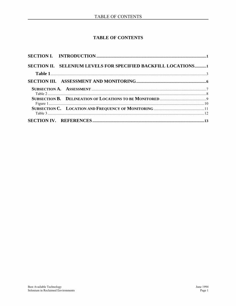
SECTION I. INTRODUCTION .................................................................................................................1
SECTION II. SELENIUM LEVELS FOR SPECIFIED BACKFILL LOCATIONS............1
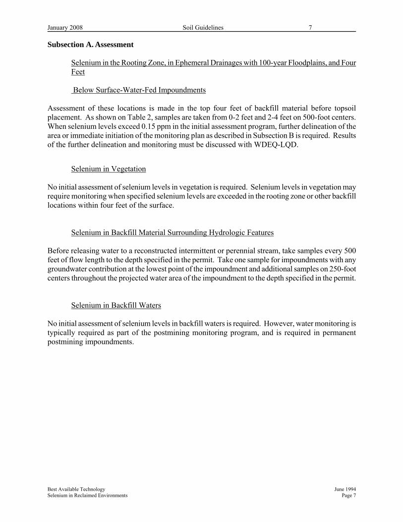
SECTION III. ASSESSMENT AND MONITORING........................................................................6
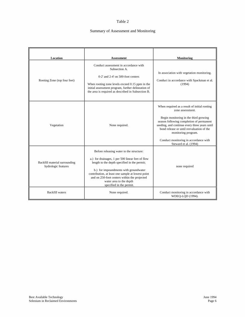
SUBSECTION A. ASSESSMENT ......................................................................................................................7 Table 2 ...................................................................................................................................................................8
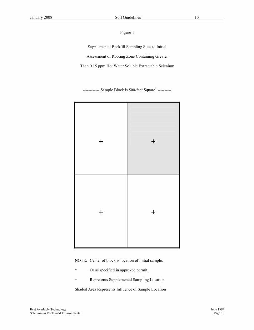
SUBSECTION B. DELINEATION OF LOCATIONS TO BE MONITORED................................................9 Figure 1................................................................................................................................................................10
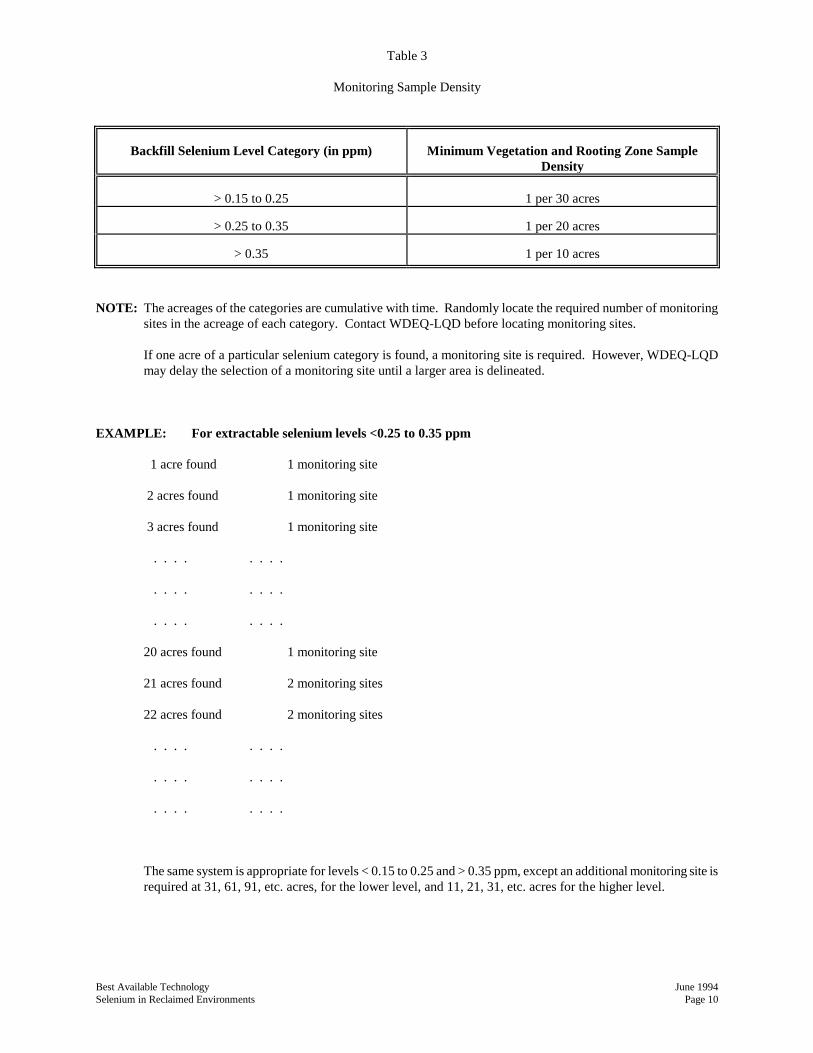
SUBSECTION C. LOCATION AND FREQUENCY OF MONITORING ....................................................11 Table 3 .................................................................................................................................................................12
SECTION IV. REFERENCES ...................................................................................................................13
January 2008 Soil Guidelines 1
Best Available Technology June 1994 Selenium in Reclaimed Environments Page 1
PLACEMENT, ASSESSMENT, AND MONITORING IN RECLAIMED
ENVIRONMENTS OF MATERIALS CONTAINING SELENIUM: A PROGRAM FOR WYOMING SURFACE COAL MINES
Section I. Introduction Selenium in the environment, while necessary for good health and nutrition, can be toxic in excess. Elevated selenium levels in aquatic and semi-aquatic environments can have serious consequences to wildlife. Studies of the Kesterson Wildlife Refuge in California (an irrigation project) and the Kendrick Irrigation Project near Casper, Wyoming, show that selenium can become harmful in the environment. The purpose of this document is to provide assistance on the placement, assessment, and monitoring in reclaimed environments of overburden containing selenium. Such assistance will help to ensure any deleterious effects of selenium will be minimized in the postmining environment. This document will remain in effect until research information becomes available to provide assistance, or until September 1994, when the document will be reviewed. Sources of research information that may be used to modify this document include WDEQ/WMA Joint Research Projects and AML projects on selenium. This document is based on the best information currently available, as well as the best judgment of a technical subcommittee convened specifically to provide such assistance. The subcommittee was composed of members of the surface coal mining industry in Wyoming and members of the Wyoming Department of Environmental Quality, Land Quality Division (WDEQ-LQD). The Appendices were developed as standard operating procedures with the assistance of the University of Wyoming and the U.S. Geological Survey. This document provides assistance to WDEQ/LQD and the mining industry. Proposed deviations should be discussed with WDEQ-LQD.
Statement of Purpose This document sets limits for selenium in the reclaimed environment beyond which monitoring, mitigation plans, and bonding will be required. The key to the program is assessment of materials for selenium following placement in the reclaimed environment. When necessary, the assessment program will be followed by a monitoring program, and in some cases, the development of mitigation plans and bonding as a result of those plans. NOTE: This document is based on selenium levels determined through the hot water soluble
extraction method. Hot water soluble analysis has been one method used historically in Wyoming. This method is not necessarily the method recommended. Refer to Section III for further discussion.
Section II. Selenium Levels for Specified Backfill Locations
January 2008 Soil Guidelines 2
Best Available Technology June 1994 Selenium in Reclaimed Environments Page 2
Assessment of selenium levels in postmining environments is required in all cases following reclamation. Table 1 identifies backfill locations and selenium levels for those locations that may require monitoring, mitigation, or bonding. As specified in Table 1, when assessment shows that selenium levels in the reclaimed environment are below a specified level, no monitoring of the backfill locations is required. Above those levels, monitoring is required, along with a commitment to develop mitigation plans and bonding should studies indicate mitigation is necessary. When assessment shows certain selenium levels in the reclaimed environment, monitoring, mitigation plans, and bonding may be required immediately following assessment. Such requirements will be based on site-specific conditions. As shown in Table 1, the thickness of most backfill comprising or underlying hydrologic features will be site-specific, and decided in consultation with WDEQ-LQD. Site specific considerations include, but are not limited to, characteristics of the backfill material, characteristics of subsurface water movement, and characteristics of the predicted postmining potentiometric surface. A plan for documentation of site specific placement may be required.
Selenium in the Rooting Zone and in Ephemeral Drainages with 100-year Floodplains When assessment shows that the four feet of material comprising the rooting zone or underlying ephemeral drainages with 100-year floodplains has less than 0.15 ppm selenium, no vegetation or backfill monitoring is required. When assessment shows that these materials have selenium levels equal to or between 0.15 and 0.45 ppm, vegetation and backfill monitoring are required in accordance with Section III, Subsection C. When extractable selenium greater than 0.45 ppm is identified during assessment of the rooting zone and ephemeral drainages with 100-year floodplains, vegetation and backfill monitoring, a mitigation plan for values that may exceed specified vegetation standards, and possibly bonding are required. If vegetation selenium levels exceeding 5.0 ppm or these levels are found to be above baseline conditions during monitoring, mitigation and possibly bonding for that mitigation will be required.
January 2008 Soil Guidelines 3
Table 1 Placement and Monitoring of Backfill Materials Containing Selenium
Selenium Level in ppm (HWS)b
Backfill Materials Found in or Surrounding:
Thickness of Backfill Material Comprising or
Underlying the Hydrologic Featurea
At this level, no
monitoring is required
At this level, monitoring is
required
Monitoring, mitigation, and possibly bonding
required
Rooting Zone and Ephemeral Drainages with 100-
year Floodplains c
<0.15
0.15 - 0.45
>0.45
4 feet
5.0 ppm dietary standard or baseline concentrations must be met for vegetation
0.10 - 0.20
>0.20
Impoundments (surface water only)
4 feet
<0.10
[5 ppb for wildlife (WQD regulations) - or baseline
conditions must be met]
Water Table
top of potentiometric surface to pit bottom
none specified; special permit conditions may prevail Intermittent or Perennial Drainages including 100-year Floodplain (no ground water interaction); and
site specific d
<0.10
0.10 - 0.20
>0.20
Intermittent or Perennial Drainages including 100-
year Floodplain (ground water interaction)
5 ppb for wildlife (WQD regulations) or baseline concentrations in water
Impoundments (surface and ground water
interaction); and
<0.10
>0.10 e
Impoundments (primarily ground water)
site specific d
5 ppb for wildlife (WQD regulations) - or baseline
conditions must be met
a excludes replaced topsoil b unless specified differently for wildlife c drainages that are designed or greater than 20 acres d site specific considerations include, but are not limited to, characteristics of the backfill material, characteristics of subsurface water movement, and
characteristics of the predicted postmining potentiometric surface. A plan for documentation of site specific placement may be required.
January 2008 Soil Guidelines 4
e If monitoring reveals levels of selenium in this environment in excess of the specified water level; a mitigation plan, and possibly bonding as a result
of that plan, must be developed.
January 2008 Soil Guidelines 5
Best Available Technology June 1994 Selenium in Reclaimed Environments Page 5
Selenium in Surface-Water-Fed Impoundments
When assessment shows that the four feet of material underlying surface-water-fed impoundments has less than 0.10 ppm selenium, water monitoring is not required. When assessment shows that the four feet of material underlying surface-water-fed impoundments has selenium levels equal to or between 0.10 and 0.20 ppm, water monitoring is required in accordance with Section III, Subsection C. When extractable selenium levels greater than 0.20 ppm are identified during assessment of the four feet of material underlying surface-water-fed impoundments, water monitoring, a mitigation plan for values that may exceed specified water quality standards, and possibly bonding for that mitigation plan are required. If water selenium levels exceed 5.0 ppb or these levels are found to be above baseline conditions during monitoring, mitigation, and possibly bonding for that mitigation will be required.
Selenium in the Water Table The water table, defined as the top of the potentiometric surface to the pit bottom, has no specific requirements for assessment, monitoring, mitigation, or bonding. However, site specific conditions will prevail. If water selenium levels exceed 5.0 ppb or these levels exceed baseline conditions, monitoring, mitigation, and possibly bonding for that mitigation will be required.
Selenium in Intermittent and Perennial Drainages and Their 100-year Floodplains When assessment shows that the material underlying intermittent and perennial drainages and their 100-year floodplains has less than 0.10 ppm selenium, water monitoring is not required. The depth of these materials is decided on a site-specific basis. When assessment shows that the material underlying intermittent and perennial drainages and their 100-year floodplains has between 0.10 and 0.20 ppm selenium, water monitoring is required in accordance with Section III, Subsection C. When extractable selenium greater than 0.20 ppm is identified during assessment of the material underlying intermittent and perennial drainages and their 100-year floodplains, water monitoring, a mitigation plan for values that may exceed specified water quality standards, and possibly bonding for that mitigation plan are required. If water selenium levels exceed 5.0 ppb or these levels are found to be above baseline conditions during monitoring, mitigation, and possibly bonding for that mitigation will be required.
Selenium in Impoundments When assessment of materials around an impoundment shows selenium levels in excess of 0.10 ppm, water monitoring, a mitigation plan, and possibly bonding may be required for that impoundment. The depth of materials that must be assessed surrounding the hydrologic feature is to be decided on a site-specific basis. If water selenium levels exceed 5.0 ppb or these levels exceed
January 2008 Soil Guidelines 6
Best Available Technology June 1994 Selenium in Reclaimed Environments Page 6
baseline conditions, monitoring, mitigation, and possibly bonding for that mitigation will be required. Section III. Assessment and Monitoring The purposes of assessment and monitoring are to document and assess the status, condition, and trend of selenium levels in the reclaimed environment. The rooting zone, backfill surrounding hydrologic features, vegetation, surface water, and groundwater in the reclaimed environment must all be assessed for selenium and may require monitoring. Table 2 summarizes the assessment and monitoring program for each of these elements of the reclaimed environment.
Sampling and Analysis Procedures for Assessment and Monitoring Collect and analyze rooting zone and backfill material samples in accordance with Standard Operating Procedures for the Sampling and Analysis of Selenium in Soil and Overburden/Spoil Material (Spackman et al., 1994). All samples must be extracted by the method (hot water soluble or AB-DTPA) currently approved in the operator's permit. In addition, twenty percent of all samples must be analyzed using an alternate extraction technique. For example, if an operator has used AB-DTPA for past analyses, 100 percent of the samples should be analyzed using this method. Twenty percent of these samples should also be analyzed using hot water soluble, saturated paste extraction, or potassium dihydrogen phosphate extraction. However, if an operator has used hot water soluble extraction for past analyses, then 100 percent of the samples should be analyzed using this method. Twenty percent of these samples should also be analyzed using one of the alternate methods described in the standard operating procedures provided in Spackman et al. (1994). Total selenium should also be determined for the 20 percent of the samples analyzed by the alternate method. Using different extraction techniques will help to clarify the relationship between the different techniques and provide information on the ultimate selection of a "best" method. Standard Operating Procedures for Determining Selenium in Water Samples (WDEQ-LQD, 1993) contains details on surface and groundwater sampling and analysis. Collect and analyze all water samples as described in this standard operating procedure. Collect and analyze vegetation monitoring samples as described in Standard Operating Procedures for Sampling Selenium in Vegetation (Steward et al., 1994).
January 2008 Soil Guidelines 7
Best Available Technology June 1994 Selenium in Reclaimed Environments Page 7
Subsection A. Assessment
Selenium in the Rooting Zone, in Ephemeral Drainages with 100-year Floodplains, and Four Feet
Below Surface-Water-Fed Impoundments
Assessment of these locations is made in the top four feet of backfill material before topsoil placement. As shown on Table 2, samples are taken from 0-2 feet and 2-4 feet on 500-foot centers. When selenium levels exceed 0.15 ppm in the initial assessment program, further delineation of the area or immediate initiation of the monitoring plan as described in Subsection B is required. Results of the further delineation and monitoring must be discussed with WDEQ-LQD.
Selenium in Vegetation No initial assessment of selenium levels in vegetation is required. Selenium levels in vegetation may require monitoring when specified selenium levels are exceeded in the rooting zone or other backfill locations within four feet of the surface.
Selenium in Backfill Material Surrounding Hydrologic Features Before releasing water to a reconstructed intermittent or perennial stream, take samples every 500 feet of flow length to the depth specified in the permit. Take one sample for impoundments with any groundwater contribution at the lowest point of the impoundment and additional samples on 250-foot centers throughout the projected water area of the impoundment to the depth specified in the permit.
Selenium in Backfill Waters No initial assessment of selenium levels in backfill waters is required. However, water monitoring is typically required as part of the postmining monitoring program, and is required in permanent postmining impoundments.
January 2008 Soil Guidelines 8
Best Available Technology June 1994 Selenium in Reclaimed Environments Page 8
Table 2 Summary of Assessment and Monitoring
Location
Assessment
Monitoring
Rooting Zone (top four feet)
Conduct assessment in accordance with
Subsection A.
0-2' and 2-4' on 500-foot centers
When rooting zone levels exceed 0.15 ppm in the initial assessment program, further
delineation of the area is required as described in Subsection B.
In association with vegetation monitoring.
Conduct in accordance with Spackman et al. (1994)
Vegetation
None required.
When required as a result of initial rooting
zone assessment.
Begin monitoring in the third growing season following completion of permanent
seeding, and continue every three years until bond release or until reevaluation of the
monitoring program.
Conduct monitoring in accordance with Steward et al. (1994)
Backfill material surrounding hydrologic features
Before releasing water to the structure:
a.) for drainages, 1 per 500 linear feet of flow
length to the depth specified in the permit;
b.) for impoundments with groundwater contribution, at least one sample at lowest point
and on 250-foot centers within the projected water area to the depth specified in the permit.
none required
Backfill waters
None required.
Conduct monitoring in accordance with
WDEQ-LQD (1994).
January 2008 Soil Guidelines 9
Best Available Technology June 1994 Selenium in Reclaimed Environments Page 9
Subsection B. Delineation of Locations to be Monitored
Selenium in the Rooting Zone, in Ephemeral Drainages with 100-year Floodplains, and Four Feet Below Surface-Water-Fed Impoundments
When assessment of the rooting zone indicates a selenium value greater than 0.15 ppm for that area, supplemental backfill sampling must occur or vegetation monitoring must be immediately initiated. Take supplemental backfill samples in the center of each quarter surrounding the original assessment sample site as shown in Figure 1. The supplemental sample represents the entire area of that quarter of the original 500 x 500 ft. area. Vegetation monitoring must be conducted in accordance with Subsection C. If all the supplemental backfill samples show selenium values lower than 0.15 ppm, no further action is necessary. However, if one or more of the supplemental samples exceed 0.15 ppm, then the area of backfill represented by that supplemental sample joins the acreage category that requires monitoring of selenium levels in accordance with Subsection C.
Materials Surrounding Hydrologic Features When further assessment or delineation of materials surrounding hydrologic features are greater than values given in Table 1 for monitoring, an approved monitoring program must occur. The operator has the option to immediately develop an approved monitoring program without the intervening step of further assessment. Monitoring programs will be developed in consultation with WDEQ-LQD on a site-specific basis.
Water Sampling Water sampling in reclaimed environments should occur in conformance with the approved permits. Deviations to the permit must be discussed and approved by the WDEQ-LQD.
January 2008 Soil Guidelines 10
Best Available Technology June 1994 Selenium in Reclaimed Environments Page 10
Figure 1 Supplemental Backfill Sampling Sites to Initial Assessment of Rooting Zone Containing Greater Than 0.15 ppm Hot Water Soluble Extractable Selenium
------------ Sample Block is 500-feet Square* ----------
+
+
+
+
NOTE: Center of block is location of initial sample. * Or as specified in approved permit. + Represents Supplemental Sampling Location Shaded Area Represents Influence of Sample Location
January 2008 Soil Guidelines 11
Best Available Technology June 1994 Selenium in Reclaimed Environments Page 11
Subsection C. Location and Frequency of Monitoring
Selenium in Rooting Zone The minimum sampling density for monitoring sites will be triggered by the selenium levels listed on Table 3. No less than one monitoring site will be required for each category. The monitoring plan will be initiated immediately following identification and determination of the selenium level to be monitored. Follow the monitoring schedule given in Table 3 for each site. The acreages of each selenium classification are cumulative with time. Categories have been developed for three ranges of selenium in the upper four feet. These categories include extractable selenium values of >0.15 to 0.25, >0.25 to 0.35, and >0.35 ppm. One additional site is required for each category after the initial 30, 20, and 10 acres of material with elevated selenium values have been identified for the categories of >0.15 to 0.25, >0.25 to 0.35, and >0.35 ppm, respectively (Table 3). Rooting zone monitoring is done in association with vegetation monitoring as described below. This rooting zone monitoring is conducted according to Standard Operating Procedures for the Sampling and Analysis of Selenium in Soil and Overburden/Spoil Material (Spackman et al., 1994).
Selenium in Vegetation Vegetation monitoring is required when the results of initial rooting zone assessment exceed 0.15 ppm extractable Se and mitigation procedures are not preformed. Monitoring shall begin in the third growing season following completion of permanent seeding, and continue every three years until bond release or until reevaluation of the monitoring program. Vegetation monitoring shall be conducted according to Standard Operating Procedures for Sampling Selenium in Vegetation (Steward et al., 1994).
Selenium in Backfill Waters All operators are responsible for conducting backfill water monitoring in accordance with an approved monitoring plan, and for submitting all routine monitoring results to the Administrator at least annually. Backfill water monitoring for the identified areas of selenium shall be conducted according to standard Operating Procedures for Determining Selenium in Water Samples (WDEQ-LQD, 1993).
January 2008 Soil Guidelines 12
Best Available Technology June 1994 Selenium in Reclaimed Environments Page 12
Table 3 Monitoring Sample Density
Backfill Selenium Level Category (in ppm)
Minimum Vegetation and Rooting Zone Sample
Density
> 0.15 to 0.25
1 per 30 acres
> 0.25 to 0.35
1 per 20 acres
> 0.35
1 per 10 acres
NOTE: The acreages of the categories are cumulative with time. Randomly locate the required number of monitoring
sites in the acreage of each category. Contact WDEQ-LQD before locating monitoring sites.
If one acre of a particular selenium category is found, a monitoring site is required. However, WDEQ-LQD may delay the selection of a monitoring site until a larger area is delineated.
EXAMPLE: For extractable selenium levels <0.25 to 0.35 ppm
1 acre found 1 monitoring site
2 acres found 1 monitoring site
3 acres found 1 monitoring site
. . . . . . . .
. . . . . . . .
. . . . . . . .
20 acres found 1 monitoring site
21 acres found 2 monitoring sites
22 acres found 2 monitoring sites
. . . . . . . .
. . . . . . . .
. . . . . . . .
The same system is appropriate for levels < 0.15 to 0.25 and > 0.35 ppm, except an additional monitoring site is required at 31, 61, 91, etc. acres, for the lower level, and 11, 21, 31, etc. acres for the higher level.
January 2008 Soil Guidelines 13
Best Available Technology June 1994 Selenium in Reclaimed Environments Page 13
Section IV. References Wyoming Department of Environmental Quality, Land Quality Division, "Standard Operating
Procedures for Determining Selenium in Water Samples", document created in a cooperative effort between the Land Quality Division and members of the Wyoming Mining Association, WDEQ-LQD, 3rd Floor West, Herschler Building, 122 W 25th St., Cheyenne, WY, 82002.
"Standard Operating Procedures for the Sampling and Analysis of Selenium in Soil and Overburden/Spoil Material", prepared by the Wyoming State Subcommittee on Selenium in Soils, Vegetation, Overburden, and Wildlife, University of Wyoming Experiment Station Bulletin No. MP-82, Department of Plant, Soil and Insect Sciences, College of Agriculture, Laramie, WY 82071, March 1994.
Operating Procedures for Sampling Selenium in Vegetation", prepared by the Wyoming State Subcommittee on Selenium in Soils, Vegetation, Overburden, and Wildlife, University of Wyoming Experiment Station Bulletin No. MP-77, Department of Plant, Soil and Insect Sciences, College of Agriculture, Laramie, WY 82071, March 1994.
O:\SoilGuide\FinalSoilGuideJan2008.doc
ATTACHMENT 1.
STATEMENT OF BEST AVAILABLE TECHNOLOGY
PLACEMENT, ASSESSMENT, AND MONITORING IN
RECLAIMED ENVIRONMENTS OF MATERIALS
CONTAINING SELENIUM: A PROGRAM FOR
WYOMING SURFACE COAL MINES
prepared by the
Joint Selenium Task Force
Results of a Cooperative Effort between the
Wyoming Department of Environmental Quality,
Members of the Wyoming Mining Association,
University of Wyoming,
and
the U.S. Geological Survey
Second Version
June 1994
TABLE OF CONTENTS
Section I. Introduction .......................................................................................................... 1
Section II. Selenium Levels for Specified Backfill Locations ............................................. 1
Section IV. References ............................................................................................................ 10
Best Available Technology June 1994
Selenium in Reclaimed Environments Page 1
PLACEMENT, ASSESSMENT, AND MONITORING IN RECLAIMED
ENVIRONMENTS OF MATERIALS CONTAINING SELENIUM:
A PROGRAM FOR WYOMING SURFACE COAL MINES
Section I. Introduction
Selenium in the environment, while necessary for good health and nutrition, can be toxic in
excess. Elevated selenium levels in aquatic and semi-aquatic environments can have serious
consequences to wildlife. Studies of the Kesterson Wildlife Refuge in California (an irrigation
project) and the Kendrick Irrigation Project near Casper, Wyoming, show that selenium can
become harmful in the environment.
The purpose of this document is to provide assistance on the placement, assessment, and
monitoring in reclaimed environments of overburden containing selenium. Such assistance
will help to ensure any deleterious effects of selenium will be minimized in the postmining
environment.
This document will remain in effect until research information becomes available to provide
assistance, or until September 1994, when the document will be reviewed. Sources of research
information that may be used to modify this document include WDEQ/WMA Joint Research
Projects and AML projects on selenium.
This document is based on the best information currently available, as well as the best
judgment of a technical subcommittee convened specifically to provide such assistance. The
subcommittee was composed of members of the surface coal mining industry in Wyoming and
members of the Wyoming Department of Environmental Quality, Land Quality Division
(WDEQ-LQD). The Appendices were developed as standard operating procedures with the
assistance of the University of Wyoming and the U.S. Geological Survey. This document
provides assistance to WDEQ/LQD and the mining industry. Proposed deviations should be
discussed with WDEQ-LQD.
Statement of Purpose
This document sets limits for selenium in the reclaimed environment beyond which
monitoring, mitigation plans, and bonding will be required. The key to the program is
assessment of materials for selenium following placement in the reclaimed environment. When
necessary, the assessment program will be followed by a monitoring program, and in some
cases, the development of mitigation plans and bonding as a result of those plans.
NOTE: This document is based on selenium levels determined through the hot water
soluble extraction method. Hot water soluble analysis has been one method
used historically in Wyoming. This method is not necessarily the method
recommended. Refer to Section III for further discussion.
Best Available Technology June 1994
Selenium in Reclaimed Environments Page 2
Section II. Selenium Levels for Specified Backfill Locations
Assessment of selenium levels in postmining environments is required in all cases following
reclamation. Table 1 identifies backfill locations and selenium levels for those locations that
may require monitoring, mitigation, or bonding. As specified in Table 1, when assessment
shows that selenium levels in the reclaimed environment are below a specified level, no
monitoring of the backfill locations is required. Above those levels, monitoring is required,
along with a commitment to develop mitigation plans and bonding should studies indicate
mitigation is necessary.
When assessment shows certain selenium levels in the reclaimed environment, monitoring,
mitigation plans, and bonding may be required immediately following assessment. Such
requirements will be based on site-specific conditions. As shown in Table 1, the thickness of
most backfill comprising or underlying hydrologic features will be site-specific, and decided in
consultation with WDEQ-LQD. Site specific considerations include, but are not
Table 1
Placement and Monitoring of Backfill Materials Containing
Selenium
Selenium Level in ppm (HWS)b
Backfill Materials Found in or Surrounding:
Thickness of Backfill Material Comprising or
Underlying the Hydrologic Featurea
At this level, no
monitoring is required
At this level,
monitoring is
required
Monitoring, mitigation,
and possibly bonding
required
Rooting Zone and Ephemeral Drainages with 100-
year Floodplains c
<0.15
0.15 - 0.45
>0.45
4 feet
5.0 ppm dietary standard or baseline concentrations must be met for vegetation
0.10 - 0.20
>0.20
Impoundments
(surface water only)
4 feet
<0.10
[5 ppb for wildlife (WQD regulations) - or baseline
conditions must be met]
Water Table
top of potentiometric surface to pit bottom
none specified; special permit conditions may prevail
Intermittent or Perennial Drainages including 100-
year Floodplain (no ground water interaction); and
site specific d
<0.10
0.10 - 0.20
>0.20
Intermittent or Perennial Drainages including 100-
year Floodplain (ground water interaction)
5 ppb for wildlife (WQD regulations) or baseline concentrations in water
Impoundments (surface and ground water
interaction); and
site specific d
<0.10
>0.10 e
Impoundments (primarily ground water)
5 ppb for wildlife (WQD regulations) - or baseline
conditions must be met
a excludes replaced topsoil
b unless specified differently for wildlife
c drainages that are designed or greater than 20 acres
d site specific considerations include, but are not limited to, characteristics of the backfill material, characteristics of subsurface water movement, and
characteristics of the predicted postmining potentiometric surface. A plan for documentation of site specific placement may be required.
e If monitoring reveals levels of selenium in this environment in excess of the specified water level; a mitigation plan, and possibly bonding as a result of that
plan, must be developed.
Best Available Technology June 1994
Selenium in Reclaimed Environments Page 4
limited to, characteristics of the backfill material, characteristics of subsurface water movement, and characteristics of the
predicted postmining potentiometric surface. A plan for documentation of site specific placement may be required.
Selenium in the Rooting Zone and in Ephemeral Drainages with 100-year Floodplains
When assessment shows that the four feet of material comprising the rooting zone or underlying ephemeral drainages
with 100-year floodplains has less than 0.15 ppm selenium, no vegetation or backfill monitoring is required. When
assessment shows that these materials have selenium levels equal to or between 0.15 and 0.45 ppm, vegetation and
backfill monitoring are required in accordance with Section III, Subsection C.
When extractable selenium greater than 0.45 ppm is identified during assessment of the rooting zone and ephemeral
drainages with 100-year floodplains, vegetation and backfill monitoring, a mitigation plan for values that may exceed
specified vegetation standards, and possibly bonding are required.
If vegetation selenium levels exceeding 5.0 ppm or these levels are found to be above baseline conditions during
monitoring, mitigation and possibly bonding for that mitigation will be required.
Selenium in Surface-Water-Fed Impoundments
When assessment shows that the four feet of material underlying surface-water-fed impoundments has less than 0.10 ppm
selenium, water monitoring is not required. When assessment shows that the four feet of material underlying surface-
water-fed impoundments has selenium levels equal to or between 0.10 and 0.20 ppm, water monitoring is required in
accordance with Section III, Subsection C.
When extractable selenium levels greater than 0.20 ppm are identified during assessment of the four feet of material
underlying surface-water-fed impoundments, water monitoring, a mitigation plan for values that may exceed specified
water quality standards, and possibly bonding for that mitigation plan are required.
If water selenium levels exceed 5.0 ppb or these levels are found to be above baseline conditions during monitoring,
mitigation, and possibly bonding for that mitigation will be required.
Selenium in the Water Table
The water table, defined as the top of the potentiometric surface to the pit bottom, has no specific requirements for
assessment, monitoring, mitigation, or bonding. However, site specific conditions will prevail.
If water selenium levels exceed 5.0 ppb or these levels exceed baseline conditions, monitoring, mitigation, and possibly
bonding for that mitigation will be required.
Selenium in Intermittent and Perennial Drainages and Their 100-year Floodplains
When assessment shows that the material underlying intermittent and perennial drainages and their 100-year floodplains
has less than 0.10 ppm selenium, water monitoring is not required. The depth of these materials is decided on a site-
specific basis. When assessment shows that the material underlying intermittent and perennial drainages and their 100-
year floodplains has between 0.10 and 0.20 ppm selenium, water monitoring is required in accordance with Section III,
Subsection C.
When extractable selenium greater than 0.20 ppm is identified during assessment of the material underlying intermittent
and perennial drainages and their 100-year floodplains, water monitoring, a mitigation plan for values that may exceed
specified water quality standards, and possibly bonding for that mitigation plan are required. If water selenium levels
exceed 5.0 ppb or these levels are found to be above baseline conditions during monitoring, mitigation, and possibly
bonding for that mitigation will be required.
Best Available Technology June 1994
Selenium in Reclaimed Environments Page 5
Selenium in Impoundments
When assessment of materials around an impoundment shows selenium levels in excess of 0.10 ppm, water monitoring, a
mitigation plan, and possibly bonding may be required for that impoundment. The depth of materials that must be
assessed surrounding the hydrologic feature is to be decided on a site-specific basis. If water selenium levels exceed 5.0
ppb or these levels exceed baseline conditions, monitoring, mitigation, and possibly bonding for that mitigation will be
required.
Section III. Assessment and Monitoring
The purposes of assessment and monitoring are to document and assess the status, condition, and trend of selenium levels
in the reclaimed environment. The rooting zone, backfill surrounding hydrologic features, vegetation, surface water, and
groundwater in the reclaimed environment must all be assessed for selenium and may require monitoring. Table 2
summarizes the assessment and monitoring program for each of these elements of the reclaimed environment.
Sampling and Analysis Procedures for Assessment and Monitoring
Collect and analyze rooting zone and backfill material samples in accordance with Standard Operating Procedures for the
Sampling and Analysis of Selenium in Soil and Overburden/Spoil Material (Spackman et al., 1994). All samples must be
extracted by the method (hot water soluble or AB-DTPA) currently approved in the operator's permit. In addition, twenty
percent of all samples must be analyzed using an alternate extraction technique. For example, if an operator has used
AB-DTPA for past analyses, 100 percent of the samples should be analyzed using this method. Twenty percent of these
samples should also be analyzed using hot water soluble, saturated paste extraction, or potassium dihydrogen phosphate
extraction. However, if an operator has used hot water soluble extraction for past analyses, then 100 percent of the
samples should be analyzed using this method. Twenty percent of these samples should also be analyzed using one of the
alternate methods described in the standard operating procedures provided in Spackman et al. (1994). Total selenium
should also be determined for the 20 percent of the samples analyzed by the alternate method. Using different extraction
techniques will help to clarify the relationship between the different techniques and provide information on the ultimate
selection of a "best" method.
Standard Operating Procedures for Determining Selenium in Water Samples (WDEQ-LQD, 1993) contains details on
surface and groundwater sampling and analysis. Collect and analyze all water samples as described in this standard
operating procedure. Collect and analyze vegetation monitoring samples as described in Standard Operating Procedures
for Sampling Selenium in Vegetation (Steward et al., 1994).
Subsection A. Assessment
Selenium in the Rooting Zone, in Ephemeral Drainages with 100-year Floodplains, and Four Feet
Below Surface-Water-Fed Impoundments
Assessment of these locations is made in the top four feet of backfill material before topsoil placement. As shown on
Table 2, samples are taken from 0-2 feet and 2-4 feet on 500-foot centers. When selenium levels exceed 0.15 ppm in the
initial assessment program, further delineation of the area or immediate initiation of the monitoring plan as described in
Subsection B is required. Results of the further delineation and monitoring must be discussed with WDEQ-LQD.
Best Available Technology June 1994
Selenium in Reclaimed Environments Page 6
Table 2
Summary of Assessment and Monitoring
Location
Assessment
Monitoring
Rooting Zone (top four feet)
Conduct assessment in accordance with
Subsection A.
0-2' and 2-4' on 500-foot centers
When rooting zone levels exceed 0.15 ppm in the
initial assessment program, further delineation of
the area is required as described in Subsection B.
In association with vegetation monitoring.
Conduct in accordance with Spackman et al.
(1994)
Vegetation
None required.
When required as a result of initial rooting
zone assessment.
Begin monitoring in the third growing
season following completion of permanent
seeding, and continue every three years until
bond release or until reevaluation of the
monitoring program.
Conduct monitoring in accordance with
Steward et al. (1994)
Backfill material surrounding
hydrologic features
Before releasing water to the structure:
a.) for drainages, 1 per 500 linear feet of flow
length to the depth specified in the permit;
b.) for impoundments with groundwater
contribution, at least one sample at lowest point
and on 250-foot centers within the projected
water area to the depth
specified in the permit.
none required
Backfill waters
None required.
Conduct monitoring in accordance with
WDEQ-LQD (1994).
Best Available Technology June 1994
Selenium in Reclaimed Environments Page 7
Selenium in Vegetation
No initial assessment of selenium levels in vegetation is required. Selenium levels in vegetation may require monitoring
when specified selenium levels are exceeded in the rooting zone or other backfill locations within four feet of the surface.
Selenium in Backfill Material Surrounding Hydrologic Features
Before releasing water to a reconstructed intermittent or perennial stream, take samples every 500 feet of flow length to
the depth specified in the permit. Take one sample for impoundments with any groundwater contribution at the lowest
point of the impoundment and additional samples on 250-foot centers throughout the projected water area of the
impoundment to the depth specified in the permit.
Selenium in Backfill Waters
No initial assessment of selenium levels in backfill waters is required. However, water monitoring is typically required as
part of the postmining monitoring program, and is required in permanent postmining impoundments.
Subsection B. Delineation of Locations to be Monitored
Selenium in the Rooting Zone, in Ephemeral Drainages with 100-year Floodplains,
and Four Feet Below Surface-Water-Fed Impoundments
When assessment of the rooting zone indicates a selenium value greater than 0.15 ppm for that area, supplemental
backfill sampling must occur or vegetation monitoring must be immediately initiated. Take supplemental backfill
samples in the center of each quarter surrounding the original assessment sample site as shown in Figure 1. The
supplemental sample represents the entire area of that quarter of the original 500 x 500 ft. area. Vegetation monitoring
must be conducted in accordance with Subsection C.
If all the supplemental backfill samples show selenium values lower than 0.15 ppm, no further action is necessary.
However, if one or more of the supplemental samples exceed 0.15 ppm, then the area of backfill represented by that
supplemental sample joins the acreage category that requires monitoring of selenium levels in accordance with
Subsection C.
Materials Surrounding Hydrologic Features
When further assessment or delineation of materials surrounding hydrologic features are greater than values given in
Table 1 for monitoring, an approved monitoring program must occur. The operator has the option to immediately
develop an approved monitoring program without the intervening step of further assessment. Monitoring programs will
be developed in consultation with WDEQ-LQD on a site-specific basis.
Water Sampling
Water sampling in reclaimed environments should occur in conformance with the approved permits. Deviations to the
permit must be discussed and approved by the WDEQ-LQD.
Best Available Technology June 1994
Selenium in Reclaimed Environments Page 8
Figure 1
Supplemental Backfill Sampling Sites to Initial
Assessment of Rooting Zone Containing Greater
Than 0.15 ppm Hot Water Soluble Extractable Selenium
------------ Sample Block is 500-feet Square* ----------
+
+
+
+
NOTE: Center of block is location of initial sample.
* Or as specified in approved permit.
+ Represents Supplemental Sampling Location
Shaded Area Represents Influence of Sample Location
Best Available Technology June 1994
Selenium in Reclaimed Environments Page 9
Subsection C. Location and Frequency of Monitoring
Selenium in Rooting Zone
The minimum sampling density for monitoring sites will be triggered by the selenium levels listed on Table 3. No less
than one monitoring site will be required for each category. The monitoring plan will be initiated immediately following
identification and determination of the selenium level to be monitored. Follow the monitoring schedule given in Table 3
for each site.
The acreages of each selenium classification are cumulative with time. Categories have been developed for three ranges
of selenium in the upper four feet. These categories include extractable selenium values of >0.15 to 0.25, >0.25 to 0.35,
and >0.35 ppm. One additional site is required for each category after the initial 30, 20, and 10 acres of material with
elevated selenium values have been identified for the categories of >0.15 to 0.25, >0.25 to 0.35, and >0.35 ppm,
respectively (Table 3). Rooting zone monitoring is done in association with vegetation monitoring as described below.
This rooting zone monitoring is conducted according to Standard Operating Procedures for the Sampling and Analysis of
Selenium in Soil and Overburden/Spoil Material (Spackman et al., 1994).
Selenium in Vegetation
Vegetation monitoring is required when the results of initial rooting zone assessment exceed 0.15 ppm extractable Se and
mitigation procedures are not preformed. Monitoring shall begin in the third growing season following completion of
permanent seeding, and continue every three years until bond release or until reevaluation of the monitoring program.
Vegetation monitoring shall be conducted according to Standard Operating Procedures for Sampling Selenium in
Vegetation (Steward et al., 1994).
Selenium in Backfill Waters
All operators are responsible for conducting backfill water monitoring in accordance with an approved monitoring plan,
and for submitting all routine monitoring results to the Administrator at least annually. Backfill water monitoring for the
identified areas of selenium shall be conducted according to standard Operating Procedures for Determining Selenium in
Water Samples (WDEQ-LQD, 1993).
Best Available Technology June 1994
Selenium in Reclaimed Environments Page 10
Table 3
Monitoring Sample Density
Backfill Selenium Level Category (in ppm)
Minimum Vegetation and Rooting Zone Sample
Density
> 0.15 to 0.25
1 per 30 acres
> 0.25 to 0.35
1 per 20 acres
> 0.35
1 per 10 acres
NOTE: The acreages of the categories are cumulative with time. Randomly locate the required number of monitoring
sites in the acreage of each category. Contact WDEQ-LQD before locating monitoring sites.
If one acre of a particular selenium category is found, a monitoring site is required. However, WDEQ-LQD
may delay the selection of a monitoring site until a larger area is delineated.
EXAMPLE: For extractable selenium levels <0.25 to 0.35 ppm
1 acre found 1 monitoring site
2 acres found 1 monitoring site
3 acres found 1 monitoring site
. . . . . . . .
. . . . . . . .
. . . . . . . .
20 acres found 1 monitoring site
21 acres found 2 monitoring sites
22 acres found 2 monitoring sites
. . . . . . . .
. . . . . . . .
. . . . . . . .
The same system is appropriate for levels < 0.15 to 0.25 and > 0.35 ppm, except an additional monitoring site is
required at 31, 61, 91, etc. acres, for the lower level, and 11, 21, 31, etc. acres for the higher level.
Best Available Technology June 1994
Selenium in Reclaimed Environments Page 11
Section IV. References
Wyoming Department of Environmental Quality, Land Quality Division, "Standard Operating Procedures for
Determining Selenium in Water Samples", document created in a cooperative effort between the Land Quality
Division and members of the Wyoming Mining Association, WDEQ-LQD, 3rd Floor West, Herschler Building,