1 document.doc Guidelines for Model-Based (System) Architecting and Software Engineering (MBASE) Inception and Elaboration Operational Concept Description (OCD) System and Software Requirements Definition (SSRD) System and Software Architecture Description (SSAD) Life Cycle Plan (LCP) Feasibility Rationale Description (FRD) Construction Iteration Plan Iteration Assessment Report Release Description Quality Management Plan Test Plan Test Description and Results Peer Review Plan Peer Review Report Transition Transition Plan User’s Manual Support
Transcript
1 document.doc
Guidelines forModel-Based (System) Architecting and
Software Engineering (MBASE)Inception and Elaboration
Operational Concept Description (OCD) System and Software Requirements Definition (SSRD) System and Software Architecture Description (SSAD) Life Cycle Plan (LCP) Feasibility Rationale Description (FRD)
Construction Iteration Plan Iteration Assessment Report Release Description Quality Management Plan Test Plan Test Description and Results Peer Review Plan Peer Review Report
Transition Transition Plan User’s Manual
Support System Software Support Plan (SSSP)
General permission to make fair use in teaching or research of all or part of these guidelines is granted to individual readers, provided that the copyright notice of the Center for Software Engineering at the University of Southern California is given, and that reference is made to this publication. To otherwise use substantial excerpts or the entire work requires specific permission, as does reprint or republication of this material.
Version controlDate Author Version Changes made1/31/00 Nikunj Mehta 1.1.0 Added some details to the LCP Approach section2/3/00 Dan Port 1.2.0 Elaborated and re-wrote parts of Invariants/Variants section
Added model classification per section guide Added model classifications to OCD, SSRD, SSAD, LCP,
FRD outlines Elaborated on Architectural Views SSAD 3.1 Added details to LCP
2/14/00 Barry Boehm 1.3.0 Elaborated several LCP sections Re-organized several LCP sections
2/18/00 Barry Boehm 1.3.1 Further elaborations to LCP BRA material added to LCP 4.3 Need to re-sync LCP sections with outline TOC
2/22/00 Ebru Dincel 1.4.0 Synchronization of Section numbers with the ones in TOC Reference check Took out course related material
2/23/00 Ebru Dincel 1.4.1 Added some abbreviations2/24/00 Ebru Dincel 1.4.2 Corrected some typos
Appendix A of MBASE moved to OCD 52/26/00 Nikunj Mehta 1.4.3 Edits and corrections.
Changed link section under LCP Approach to bullets2/29/00 Ebru Dincel 1.4.5 Edits and corrections to LCP7/10/00 Dan Port 1.5 Updated OCD, added CTS8/1/00 Dan Port 1.5.1 Moved material after FRD to after CTS8/7/00 Ebru Dincel 1.5.2 LCP Rework, split participants into agents8/14/00 Dan Port 1.6 Updated OCD, reworked SSRD (removed User Classes,
moved Typical Levels of Service table to OCD), reworked SSAD (sample specification templates, object model)
8/20/00 Ebru Dincel 1.7 New OCD 2.08/28/00 Dan Port 1.7.1 Lots of OCD and SSRD revisions, added Degree of Detail
and Tailoring sections8/31/00 Dan Port 1.8 More SSRD revisions, LCP and FRD revisions9/4/00 Dan Port 1.9 Added Course Guidelines to all sections9/5/00 Ebru Dincel 2.0 RUP related material11/19/00 A W Brown 2.0a SSRD RUP related material repaired based on LCO ARB11/24/00 A W Brown 2.0c Rest of RUP related material repaired based on LCO ARB12/24/00 A W Brown 2.0d RUP related material based on 2000 LCA ARB 12/10/00 Ebru Dincel 2.1 Corrected some reference errors in SSRD1/6/01 A W Brown 2.1.1 2.0d merged with 2.11/25/01 Dan Port 2.2 Added revised Support Plan (SSSP), clarifications to many
sections based on CS577a 2000 ARB reviews, COTS Integration special emphasis, expanded introduction to prototypes OCD 5
9/2/01 Edward Colbert
2.3 Revised RUP Guidelines in SSAD Renamed following components of SSAD
Design Component Specification as Component Implementation Design Model
Logical Component View as Logical Class Model Object Static Structure Model as Object Structure
Model Operations Model as Interaction Model Classification Model as Implementation Class Model
3 document.doc
Revised SSAD 3.1.2 Component Implementation Model Revised SSAD 3.5 Configuration Model and added RUP
Guidelines.9/6/01 Dan Port 2.3.1 Removed introduction material (now in separate document)
Added Jung-Won’s new weekly effort form in appendix Removed COTS integration spiral from 3.1.2 Component
Implementation Design Model (reference to new supplement added)
9/26/01 Ed Colbert 2.3.2 In SSAD, Minor revisions to package naming convention in
RUP Guidelines in sections 2.1, 3.1.1, and 3.1.4 Replaced RUP Guideline in section 2.3 with separate
guidelines in sections 2.3.1 and 2.3.2. Added RUP Guideline to section 3.1.2 Removed “LCA” from headers of RUP Guidelines Added LCO–, LCA–, and IOC–specific guides to
RUP Guidelines. In SSRD,
Revised section 3.2. Remove subsection headers & merged the discussion
that was in those subsections into the discussion for section 3.2.
Removed RUP Guidelines for creating a use–case model.
Removed RUP Guidelines for creating a use–case model from section 6.1.
10/5/01 Ed Colbert 2.3.3 In OCD, Added 577a Guidelines to Section 2.1.2. Added RUP Guidelines to Section 2.3. Revised RUP Guidelines in Sections 3.4, 3.5, 4.3,
4.5, and 4.5.2. In SSRD,
Removed RUP Guidelines for creating a use–case model from section 3.2.
Removed RUP Guidelines for creating a use–case model from section 6.1.
01/13/02 Ed Colbert and A W Brown
2.3.4 Minor edits Change Control Summary section, such as 1.3 for OCD added
for 577 to each document with "references" Added Section 1.1 and 1.2 to Test Plan for consistencies
01/14/02 A W Brown 2.3.5 Generalized "Inspections" to COQUALMO's "Peer Reviews" Growing "plans" tree with versions required earlier
01/31/02 A W Brown 2.3.6b Color code changes of 2.3.4 and 2.3.5 in dark red (changes made) or orange (changes [deletions?] to be made).
Today's changes color coded in RED; to be changed to day in brown.
Significant changes in LCP section 4, Quality Management Plan, Peer Review Plan, Peer Review Report, and Weekly status report.
01/31/02 Ed Colbert 2.3.6b Revised RUP Guideline in Section 3.5.
4 document.doc
General GuidelinesPlease read the following general guidelines carefully, before proceeding to the guidelines for the individual deliverables.
MBASEModel-based System Architecting and Software Engineering (MBASE) is an approach that integrates the process (PS), product (PD), property (PY) and success (SS) models for developing a software system. The essence of the approach is to develop the following system definition elements concurrently and iteratively (or by refinement) using the Win–Win Spiral approach defined in [Boehm, 1996].
Operational Concept Description (OCD) System and Software Requirements Definition (SSRD) System and Software Architecture Description (SSAD) Life Cycle Plan (LCP) Feasibility Rationale Description (FRD) Construction, Transition, Support (CTS) plans and reports Risk-driven prototypes
The three critical project milestones are the Life Cycle Objectives (LCO), Life Cycle Architecture (LCA), and the Initial Operating Capability (IOC). The system definition elements have to satisfy specific completion criteria at each anchor point. The system definition elements are strongly integrated and a strong traceability thread ties the various sections:
e.g., the System Definition (documented in the SSRD) is a refinement of the Statement of Purpose (documented in the OCD). Therefore, to enforce conceptual integrity, it is essential that team members work collaboratively, particularly on strongly related sections.
Due to the strong interdependencies, it may be a good idea to follow some order when producing the deliverables, at least initially: e.g., write core sections of the OCD before the SSRD. During successive iterations, the documents generally should not be traversed in a linear fashion. Forward consistency should always be enforced (if an Entity is added to the Entity Model, then it should be examined as to how it affects the Component Model). Backward consistency can be less strongly enforced, but is useful to do where feasible.
Strongly dependent sections are indicated by [Consistent with DDD x.x.x] where DDD is the LCO/LCA deliverable, and x.x.x the section number. When reviewing the deliverables and checking the overall conceptual integrity, it is very helpful to review strongly connected sections in sequence (e.g., OCD: Statement of Purpose, SSRD: System Definition), as opposed to reviewing the deliverables in a linear fashion.
Conceptual integrity and consistency between the various deliverables, at a given milestone (LCO/LCA), is critical. In particular, a system definition element should not be "incomplete" with respect to the remaining ones. For instance, if the SSRD specifies more requirements, than the architecture described in the SSAD supports, but the FRD claims that the architecture will satisfy all the requirements, the SSAD would be considered incomplete. It is important to reconcile the deliverables, and make sure that one deliverable is not "one iteration ahead" of the other deliverables.
The general differences between the LCO, LCA and the IOC are as follows:Life Cycle Objectives (LCO): less structured, with information moving around focus on the strategy or "vision" (e.g., for the Operational Concept Description and Life Cycle Plan), as
opposed to the details could have some mismatches (indicating unresolved issues or items) no need for complete forward and backward traceability may still include "possible" or "potential" elements (e.g., Entities, Components, …) some sections could be left as TBD, particularly Construction, Transition, and Support plans Life Cycle Architecture (LCA): more formal, with solid tracing upward and downward no major unresolved issues or items, and closure mechanisms identified for any unresolved issues or items
(e.g., “detailed data entry capabilities will be specified once the Library chooses a Forms Management package on February 15”)
no more TBDs expect possibly within Construction, Transition, and Support plans
5 document.doc
basic elements from the Life Cycle Plan are indicated within the Construction, Transition, and Support plans
there should no longer be any "possible" or "potential" elements (e.g., Entities, Components, …) no more superfluous, unreferenced items: each element (e.g., Entities, Components, …) either should
reference, or be referenced by another element. Items that are not referenced should be eliminated, or documented as irrelevant
Initial Operating Capability (IOC): complete tracings within and between models, delivered software (e.g. comments in code trace to SSAD
design elements) MBASE models are updated to be consistent (but not necessarily complete) with delivered system, that is
“as built” OCD, SSRD, SSAD, etc. models core system capability requirements have been implemented and tested at least one construction interaction complete set of CTS plans and reports consistent with the development completedFor further information: Refer to the completion criteria for each deliverable, for each phase.
The Completion Criteria for each LCO/LCA deliverable, within the LCO/LCA phase respectively, can be used as "Exit criteria". There is no mandated number of pages per se, for a deliverable. Each package should meet all the phase completion criteria, and should thus contain the pertinent information. It is generally desirable to minimize the amount of detail, through conciseness: "less is more", as long as it conveys the appropriate amount of information, and meets all the exit criteria.
The level of detail of each section should be risk-driven. For example, interface specification between the projects should be rigorously specified, as it is very risky to leave them ambiguous. However, one should avoid premature rigorous specification of user screen layouts, as it is risky to lock these in before users have had a chance to interact with them, and GUI-builder tools make it a low risk to iterate the screens with the users.
Use visual models (whenever possible) such as for: OCD/SSRD: block diagrams, context diagrams OCD/SSRD/SSAD: UML diagrams LCP: tables, Gantt charts, PERT charts
Repetition of information within the various deliverables should be discouraged, and referencing the information should be encouraged. It is not enough to make things consistent by SIMPLY repeating sections. For example, there is no need to repeat the System Requirements in the Feasibility Rationale. The feasibility rationale should establish the feasibility and consistency of the operational concept, requirements, architecture, prototypes and plans, with respect to particular (referenced) System Requirements. While redundancy, among other deficiencies, leads to lengthy and repetitious documentation and creates extra update-consistency problems, referencing items enforces traceability.
When referencing, avoid having: “broken” or invalid references (e.g., references to something, such as Project Goal, Entity, Component, etc.,
that does not exist) “blind” or vague references (e.g., “See FRD 2.2.3”—What exactly in FRD 2.2.3 is relevant?).
If assumptions are made in the LCO/LCA package, it is important to reality-check the assumptions as much as possible. If you say somewhere "This assumes that COTS package will do X", determine the likelihood that the assumption is true. If the likelihood is low, identify this as a risk, and determine a risk management strategy for it. Avoid introducing non-customer and non-domain-expert assumptions.
Do not just include text from the guidelines or outside sources in your deliverables, without relating the material to your project's specifics: no need to repeat in great detail software engineering principles and explanations taken from elsewhere.
A primary characteristic of the MBASE process is to be risk driven at all times (see MBASE invariant 5). Use this to help resolve tricky “how much should be specified” problems. Note that the assumption “more is better” and “It doesn’t hurt to have extra” often may introduce added risks (such as confusion, presumptive specification, decreased coherence and cohesion, etc.). The risk principle may often be applied as follows: If it’s risky not to specify precisely, Do (e.g., a safety-critical hardware-software interface) If it’s risky to specify precisely, Don’t (e.g., a GUI layout that can be easily evolved to match uncertain
user needs with a GUI-builder)
Edward Colbert, 01/03/-1,
What "phases"? The term phase is not mentioned before this point. Should this be “milestones”
Edward Colbert, 01/03/-1,
What is an LCO/LCA phase?
6 document.doc
General Formatting Guidelines There should be an explanation after each heading for the following subheadings: i.e., no two headings should
be immediately next to each other. All documents should have the following information on the cover page
- Document Title- Project Title- Team- Team Members and Roles- Date- Document Version Control Information
In general, use an outline form, e.g., for Organization Activities, instead of wordy paragraphs. In an outline form, items are easier to read, and important points stand out.
Use numbered lists as opposed to bulleted lists to be able to reference items by their number, e.g., 'Organization Goal #2', which helps traceability.
Include captions for each figure, table, etc., to encourage referencing and enforce traceability.
Final RemarkWe can only suggest outlines for the LCO/LCA/IOC deliverables: in particular, there is no one-size-fits-all Requirements Description, or Life Cycle Plan structure. Authors should consider all of the items in the outline. If some of them are not applicable, it should be noted as "Not applicable" or "N/A" for future reference with some justification as to why this is so. Do not feel compelled to artificially create information simply to fill out a section that is not applicable to your project. Similarly, the document outline can be expanded if there is a need. However, it is not recommended to radically change the ordering of the various sections and to freely delete critical sections. The overriding goal is clear, concise communication. Standardized guidelines help with this: if you make substantial alterations, make sure they are clear, and well justified. Haphazard documentation is a major point of project failure.
Conventions UsedThe following conventions are used in the guidelines.
Common Pitfalls: to warn against common mistakes
Variant Guidance
The RUP and 577 variants are usually located at the end of the applicable section. Since the main, non-variant guidelines are designed for a tool-less, text-only product, process and property model representation, intelligent application of the variant guidelines is appropriate. Also, the variant guidelines must take precedence over the main text of the section. With these variants, keep in mind that these may not always apply well to your particular project and the extent of your use of RUP needs to be risk driven.
The order of presentation of material in a document does not necessarily imply the order of generation based on any given process or method. The MBASE documents and the order of presentation in them represent a variant (or even multiple variants). There can even be differences based on individual methods or methodologies.
RUP GL
This heading in the rest of the document indicates model variants compatible with the Rational Unified Process's use of UML and/or using Rose UML diagrams. Since the main, non-variant guidelines are designed for a tool-less, text-only product model and the variant guidelines take precedence, do not include in text any information that is evident from a Rose diagram. This would include connectivity between actors and use–cases, or relations between classes, including multiplicity, etc.
Different Object Oriented Analysis and Design (OOA&D) approaches are often characterized with such phrases as "Use-case and Class first" or "object and behavior (operations) first", etc. The MBASE RUP variant used in CS577
7 document.doc
follows the Use-case and Class first approach. However, it deviates from the Rational RUP approach to reflect the existence of legacy systems and COTS components as part of the solution.
Rational Rose calls the set of models and diagrams a model file. CS577 uses the UML constructs available in Rose on multiple diagrams to represent views of the various MBASE models, such as the Classification Model and the Enterprise Classification Model. Rose still does not support all of UML, and conventions are still appropriate, like reading and association between classes from left to right or top to bottom reading. Rose introduces the concept of a "package" which is, according to Rose's Help System, "a general-purpose model element that organizes model elements into groups. A system may be thought of as a single, high-level package, with everything else in the system contained in it." Rose also has it's own fixed, high-level packages, the "Use Case View" and the "Logical View", whose names can not be changed. Since MBASE has a much richer concept of product models for different purposes, Rose's fixed, high level packages are used as containers for MBASE-specific packages. The MBASE CS577 "Use Case View" contains the packages for the models of the OCD and the SSRD, while the "Logical View" contains the packages for the models of the SSAD. Also included are packages to facilitate the mapping of elements between and among the MBASE product models, thus allowing different levels of detail and completeness in diagrams and documents.
Rose supports the concept of Frameworks. A framework in Rational Rose is a set of predefined model elements that are needed to model a certain kind of system. An "MBASE CS577" framework is provided which is a partially populated Rational Rose™ model file, organized to complement the MBASE life-cycle process and models. The "MBASE CS577" framework can be added to the \Framework\Frameworks folder in your Rational Rose installation folder. The "MBASE CS577" framework contains both the package structure as well as references to RUP guidance on the diagram contents.
577 Guidelines: This heading in the rest of the document indicates MBASE variants for CS577. Since CS577 uses Rose for UML diagramming tool for Object Oriented Analysis and Design, the 577 Guidelines include ALL the RUP GL's, even if not explicitly stated. In general, the MBASE active templates (from the EPG) also contain recommended CS577 variants that may not be indicated in the guidelines (however they are typically applicable to general classes of large software projects). Since the MBASE active templates also contain fields for the tool-less, text-only product models, they should be used with the same cautions as any software project, namely the guidelines should be tailored to the particular types and sizes of projects [in the CS577] class on a case by case, risk driven basis.
8 document.doc
Operational Concept Description (OCD)
Purpose Describe the overall context of the system to be developed, why it's being built, what exists now, and where the
project is starting from Describe to the stakeholders of the system to be developed (“developed” is meant to include such terms as
“enhanced”, “updated”, “re-engineered”, "automated"), how the system will work in practice once it is deployed Enable the operational stakeholders to evolve knowledgeably from their current operational concept to the new
operational concept, and to collaboratively adapt the operational concept as developments arise, to make clear the value of developing the new system
Establish goals and other success criteria, establish basis of value assessment (for use in FRD Business Case)
Completion CriteriaThe following paragraphs describe the completion criteria for OCD at the three project milestones.
Life Cycle Objectives (LCO) Top-level system objectives and scope
Organization Context and Goals Current system overview and shortfalls System Capability Description for proposed system System Boundary: project focus System Environment Evolution Considerations
Operational concept Operational stakeholders identified Organizational responsibilities determined and coordinated with clients Main operational scenarios coordinated with clients System Concept
Shared vision and context for stakeholders Common vision and goals for system and its evolution Common language and understanding of system constraints Results Chain linking system development initiative with other initiatives and assumptions necessary to
achieve overall system goals Operational concept satisfiable by at least one system/software architecture Capabilities rationalized by business case analysis in Feasibility Rationale Description
Life Cycle Architecture (LCA) Elaboration of system objectives and scope by system increment Elaboration of operational concept by system increment All stakeholder-critical nominal and off-nominal scenarios coordinated with clients Operational concept satisfiable by the architecture in the SSAD Tracing between Project Goals, and Organization Goals and Activities Tracing between Capabilities and Project Goals and Organization Activities
Initial Operational Capability (IOC) Update of LCA OCD which is consistent with other IOC updates of the LCA packages, and with the IOC Transition Plan and Support Plan
Intended Audience Customer and operational stakeholders for Domain Description and shared vision Domain Experts and for initial System Analysis Use language, and operational stakeholders define CDL, appropriate to intended audience
9 document.doc
Participating Agent Same stakeholders as WinWin negotiation Establish a concept of operation that all stakeholders agree uponPerforming Agent Cs577 team
High-Level Dependencies WinWin negotiations give:
Capabilities (Priority and Rationale for proposed changes) Terms for the Domain Description Project Goals and Constraints Levels of Service
OCD yields: Project, Capability and Level of Service Requirements for SSRD Domain Description and Initial Analysis for SSAD Stakeholder and Organizational Responsibilities for LCP Business Case Analysis parameters for FRD
Degree of Detail and Tailoring The degree of details of the OCD should be risk-driven (as with any MBASE model). If it’s risky to put an item in (e.g., organizational relationships undergoing re-negotiation), don’t put it in. If it’s risky not to put an item in (e.g., project constraints on interoperability with other systems), do put it in. Sections of the OCD may be tailored down or consolidated for small or non-critical, well defined systems.
10 document.doc
Outline1. Introduction
1.1 Purpose of the Operational Concept Description Document1.2 References1.3 Change Control Summary
2 Shared Vision (SS)2.1 System Capability Description (SS)
2.1.1 Benefits Realized 2.1.2 Results Chain
2.2 Key Stakeholders (PY)2.3 System Boundary and Environment (PD)2.4 Major Project Constraints (PY)2.5 Top-Level Business Case (SS)2.6 Inception Phase Plan and Required Resources (PY)2.7 Initial Spiral Objectives, Constraints, Alternatives, and Risks (SS, PY)
3. Domain Description3.1 Organization Background (PD)3.2 Organization Goals (SS)3.3 Current Organization Activity Model (PD)3.4 Description of Current System (PD)3.5 Current Entity Model (PD)3.6 Interaction Model (PD)3.7 Current System Shortfalls (SS)
4. Proposed System4.1 Statement of Purpose4.2 Project Goals and Constraints (PY, SS)4.3 Capabilities (PD)4.4 Levels of Service (PY)4.5 Proposed System Description (PD)
5.2.1 Scope and Extent5.2.2 Participants5.2.3 Tools5.2.4 Revision History
5.3 Initial Results5.4 Conclusions
6. Common Definition Language for Domain Description(PD)7. Appendix
11 document.doc
1. Introduction
1.1 Purpose of the Operational Concept Description Document This paragraph shall summarize the purpose and contents of this document and identify the project stakeholders
- Current life cycle phase or milestone (e.g., LCO version of OCD) The specific system whose operational concept is described here: [name-of-system] Its operational stakeholders: [Describe the stakeholder roles and organizations] Use specific names, titles and roles
Show how your particular Operational Concept Description meets the completion criteria for the given phase or milestone
Suggested baseline wording is provided in the MBASE Electronic Process Guide (EPG) template
Common Pitfalls: Simply repeating the purpose of the document from the EPG template or guidelines
1.2 References Provide complete citations to all documents, meeting results, and external tools referenced or used in the
preparation of this document and their outputs. This should be done in such a manner that the process and information used can be traced and used to
reconstruct the document if necessary
577 Guidelines: A "complete citation" for CS577 should include the title of the document (in suitable bibliographic form), and with the explicit URL for the document. [This information is requested so that future researchers can find the cited document from an on-line archive.]
1.3 Change Control Summary577 Guidelines: For versions of the OCD after LCO, include a summary of changes made in the document to ease the review process.
2. Shared VisionAlmost certainly, your project will have to work out some changes in its direction during the course of its development. These may come from new developments in your COTS products, reusable components, or application infrastructure. They may come from changes in your clients’ or other stakeholders’ priorities, organization or personnel. They may come from discovery of alternative systems that may solve (parts of) your application problem. When these changes come, the most valuable thing your project can have is a shared vision among its stakeholders of the project and system’s goals, objectives and strategies and of each stakeholder’s roles and responsibilities in achieving these. Although the details of the shared vision may need to be modified after the initial prototype and stakeholder win win negotiations are completed, it is crucial to obtain an initial version of the shared vision that is” brought into “ by the system’s success-critical stakeholders as early as possible. The Organization Goals in Section 3.2 and the shared vision elements below are the primary sources of the traceability relations among the MBASE documents.
2.1 System Capability DescriptionA concise description of the system that can pass the “elevator test” described in Geoffrey Moore’s Crossing the Chasm (Harper Collings, 1991, p.161). This would enable you to explain why the system should be built to an executive while riding up or down an elevator. It should take the following form:
For (target customer) Who (statement of the need or opportunity) The (product name) is a (product category) That (statement of key benefit-that is, compelling reason to buy)
12 document.doc
Unlike (primary competitive alternative) Our product (statement of primary differentiation)
Here is an example for a corporate order-entry system: “Our sales people need a faster, more integrated order entry system to increase sales. Our proposed Web Order system would give us an e-commerce order entry system similar to Amazon.com’s that will fit the special needs of ordering mobile homes and their aftermarket components. Unlike the template-based system our main competitor bought, ours would be faster, more user friendly, and better integrated with our order fulfillment system.
2.1.1 Benefits RealizedMany software projects fail by succumbing to the “Field of Dreams” syndrome. This refers to the American movie in which a Midwestern farmer has a dream that if he builds a baseball field on his farm, the legendary players of the past will appear and play on it (“Build the field and the players will come”).In the The Information Paradox [Thorp 1999], John Thorp discusses the paradox that organizations’ success in profitability or market capitalization do not correlate with their level of investment in information technology (IT). He traces this paradox to an IT and software analogy of the “Field of Dreams” syndrome: “Build the software and the benefits will come”.To counter this syndrome, Thorp and his company, the DMR Consulting Group, have developed a Benefits Realization Approach (BRA) for determining and coordinating the other initiatives besides software and IT system development that are needed in order for the organization to realize the potential IT system benefits. MBASE has adapted some key BRA features that help a software project and its stakeholders to develop and utilize a realistic shared vision. The most significant of these features, the Results Chain, is discussed next.
2.1.2 Results ChainFigure 1 shows a simple Results Chain provided as an example in The Information Paradox. It establishes a framework linking Initiatives that consume resources (e.g., implement a new order entry system for sales) to Contributions (not delivered systems, but their effects on existing operations) and Outcomes, which may lead either to further contributions or to added value (e.g., increased sales). A particularly important contribution of Results Chain is the link to Assumptions, which condition the realization of the Outcomes. Thus, in Figure 1, if order to delivery time turns out to be an important buying criterion for the product being sold, the reduced time to deliver the product will not result in increased sales.It establishes a realizing desired value. It also provides a valuable framework by which your project can work with your clients to identify additional non-software initiatives that may be needed to realize the potential benefits enables by the software/IT system initiative. These may also identify some additional success-critical stakeholders who need to be represented and “brought into” the shared vision.
For example, the initiative to implement a new order entry system may reduce the time required to process orders only if some additional initiatives are pursued to convince the sales people that the new system will be good for their careers and to train them in how to use the system effectively. And the reduced order processing cycle will reduce the time to deliver products only if additional initiatives are pursued to coordinate the order entry system with the
INITIATIVE OUTCOME OUTCOME
ASSUMPTION
Contribution Contribution
Implement a new order entry system
Reduce time to process order Reduce order-processing cycle
(intermediate outcome)
Reduce time to deliver product
Increased sales
Order to delivery time is an important buying criterion
Edward Colbert, 01/03/-1,
This description is a more detailed explanation then similar sections in the SSAD. Which is intended? Should there be a statement about what the student should put here? This section is better written
13 document.doc
order fulfillment system (Some classic cases where this didn’t happen were the late Hershey’s chocolate Halloween candy deliveries and the late Toys’R’Us Christmas toy deliveries).Such additional initiatives need to be added to the Results Chain. Besides increasing its realism, this also identifies additional success-critical stakeholders (sales people and order fulfillment people) who need to be involved in the system definition and development process.
577a GL: OCD 2.1.2 – Results Chain
Use one Static-Structure Diagram for each Results Chain. Each initiative, outcome, and assumption should be represented a classifier with a stereotype of either <<initiative>>, <<outcome>>, or <<assumption>>, as appropriate. The label of the classifier should describe the initiative, outcome, and assumption. Each contribution should be represented as directional association with the stereotype <<contribution>>. Each assumption should be connected to one or more outcomes using a bi–directional association.
2.2 Key StakeholdersIdentify each stakeholder by their home organization, their authorized representative for project activities, and their relation to the Results Chain. The four classic stakeholders are the software/IT system’s users, customers, developers and maintainers. Additional stakeholders may be system interfacers (the order fulfillment people above), subcontractors, suppliers, venture capitalists, independent testers, and the general public (where safety or information protection issues may be involved).
Common Pitfalls: Being too pushy or not pushy enough in getting your immediate clients to involve the other success-critical
stakeholders. Often, this involves fairly delicate negotiations among operational organizations. If things are going slowly and you are on a tight schedule, seek the help of your higher-level managers.
Accepting just anybody as an authorized stakeholder representative. You don’t want the stakeholder organization to give you somebody they feel they can live without. Some good criteria for effective stakeholders are that they be empowered, representative, knowledgeable, collaborative and committed collaborative and committed.
2.3 System Boundary and EnvironmentThe system boundary distinguishes between the services your project will be responsible for developing and delivering and the stakeholder organizations and interfacing systems for which your project has no authority or responsibility, but with which your project must coordinate to realize a successful software/IT system and its resulting benefits. Figure 2 shows the context diagram used to define the system boundary. It shows type of information that may be included in a context diagram, but is not intended to be a one-size-fits-all template.
Figure 2 Context Diagram.
Service users
<List Services Provided>
System Administrators
Critical interfacing systems
Data sourcesInfrastructure
14 document.doc
The Context Diagram for the proposed system should include entities for all the key operational stakeholders described below (OCD 2.2)
The Services provided box defines the system boundary. It should just contain a list of top-level services that your system will provide. For example, besides “Order entry” in the example above, will your project be responsible for providing an “Order authentication” service? It is important to identify services at this level, but not to make design decisions about details such as credit card verification or electronic signature functions.
Common Pitfalls: Including a System Block Diagram: a block diagram clearly includes top-level designs (sometimes some low-
level too), which is too early in System Analysis. A System Block Diagram belongs in the System Definition (SSRD 2.1)
Not including on the Context Diagram (OCD 3.1.1) all the key operational stakeholders
RUP GL: OCD 2.3 – System Boundary and Environment
Create a Static-Structure Diagram that represents the system as a classifier with a stereotype <<system>> and a label that consists of the name of the system and a list of services provided by the system. Each service should have the stereotype <<service>>. Each stakeholder should be represented as an actor (e.g. a classifier with the stereotype <<actor>>). If a stakeholders is a specialization of another stakeholder (e.g. “Student” and “Library User”), then show a generalization relation from the specialized stakeholder to the general stakeholder. Each stakeholder should be connected to the system by a bi–directional association. (The association is inherited by a specialized stakeholder, so an explicit association between the specialized stakeholder and the system need not be shown.)
2.4 Major Project ConstraintsSummarize any constraints that are critical to the project’s success, such as: The project must be completed rapidly to sustain the company’s competitive edge. The user interface must be compatible with other company systems. The system must be able to adapt to changes in Internet sales tax laws.
Special focus: Further Shared Vision Elements for Large SystemsFor small and/or rapid development projects, a top-level Results Chain, definition of stakeholders, and definition of the system’s boundary, primary services provided, and primary environmental entities are enough to get the Inception phase started off in the right direction. For large projects in which even the Inception phase will be a substantial commitment of stakeholders’ human and financial resources, a more substantial Inception Readiness Review (IRR) package and process is generally warranted. In the COCOMO II model [Boehm et al., 2000, p. 305], the IRR marks the beginning of the Inception phase for cost and schedule definition purposes.For large projects, the following sections should be added to the Shared Vision section and reviewed by the IRR.
2.5 Top-Level Business CaseDetailed business-case guidelines are provided in Section 2.1 of Feasibility Rationale Description (FRD 2.1). For the top-level business case, it is sufficient to estimate the costs of each of the initiatives in the Results Chain, and compare them with the quantitative and qualitative benefits realized in the Results Chain outcomes.
2.6 Inception Phase Plan and Required ResourcesThe stakeholders committing to the Inception Phase need a reasonable estimate of how much in human and financial resources their commitment involves. They also need visibility into the major activities to be undertaken in the Inception Phase.
2.7 Initial Spiral Objectives, Constraints, Alternatives, and RisksThese will be elaborated and analyzed during the Inception Phase, but again, the stakeholders need some pre-commitment understanding of them, particularly the major risks. They should be consistent with OCD 2.4, Major Project Constraints.
15 document.doc
3. Domain DescriptionThe Domain Description (which focuses on the current system and organization) elaborates the context for the system summarized in Section 2.3. It consists of several views, which describe the domain of the project (i.e., the context in which the project will be developed and deployed, including the organization, stakeholders, etc.) at various levels of generality from the customer's and domain expert's perspective. The scope of the views should be more general than the proposed (and current) system but not so general that it is impossible to resolve details within the Shared Vision (OCD 2). Overall the Domain Description should strive to maintain relevance to the Shared Vision. It provides the distilled rationale for the following: Why the system is being built (refers to, but does not repeat results and benefits from OCD 2.1) What are the backgrounds of the organizations the current system is deployed in or interacts with, and what are
the current system’s overall organization goals and activities (refers to, but does not repeat Key Stakeholders OCD 2.2)
Where the project is starting from (i.e. "what" is there at present to build upon, what is missing, and what is needed, etc.), what is the current system, what are the shortfalls of the current system — may refer to OCD 2.3)
How specific or general is the current system to the organization(s) – is it mission critical, custom built, specific to the organization(s) or is it generic, commercial off the shelf ? Somewhere in between?
The goal is to describe the organizations as relevant to the project, and provide a working context for the System Analysis (“What” the proposed system is precisely). The working context serves to avoid building a system that is too general by restricting its scope to what adds value for the critical stakeholders; this provides a tangible means to measure what is or is not relevant to the project.All sections of the Domain Description should be written in a language understood by all the stakeholders in the project, in particular customers and domain experts. This generally means describing concepts at a high, non-technical level.
577 GuidelinesDon't go too high in the organization for your project's organization background and goals. USC's overall goals may include improving USC's rank in lists of the top U.S. universities, but it is too hard to relate the project goals for a multimedia archive to such organization goals. We recommend using USC's Digital Library Initiatives as an appropriate organizational context. Here is a working good statement for these initiatives:"To make USC’s reference materials more rapidly, reliably, easily and effectively accessible to theUSC community, subject to appropriate information protection, fairness, and economic constraints."At the level of organization goals shown above, the mapping to project goals is more meaningful and straightforward. For your library information system, it is appropriate to elaborate these overall organizational goals to relate to your project goals (e.g., defining an aspect of "easily accessible" as bringing the reference materials to the user rather than vice versa), or to particular goals of your client’s organization (e.g., Seaver Science Library, Marshall School of Business Library).
3.1 Organization Background Provide a brief overview (a few sentences) of the organization (within the project's context) sponsoring the
development of this system Provide brief overview (a few sentences) of the organization that would be the end user and maintainer of the
system (these may or may not be the same as the sponsoring organization) Include the above organizations’ mission statements and/or their objectives and goals (summarize relevant
portions)
3.2 Organization Goals Identify the broad and high-level objectives and/or aspirations of the sponsoring organization(s) and of
representative organizations using the system. The goals should be relevant to, but independent from, the proposed system. System-specific goals would be documented as Project Goals (OCD 4.1). In particular the organization goals should be expressed (perhaps by referencing) in terms of the Benefits Realized (OCD 2.1).
Edward Colbert, 01/03/-1,
Reword Most of the items under “where” start with “what”.
Edward Colbert, 01/03/-1,
Reword What does “impossible to resolved details…” mean?
16 document.doc
Include only the goals that indicate what the organization wishes to achieve by having the proposed system, e.g., increase sales, profits, and customer satisfaction
The Organization Goals should be Measurable and Relevant to the current project (M.R.). Use a brief enumerated list, e.g.:
Increase sales and profits via more efficient orders processing Improve speed via faster order entry Improve quality via better in-process order visibility, reduced order defects Improve customer satisfaction via better and faster operations
Test Questions for M.R.: By LCA, each organization goal should be able to clearly answer:M: "What is a measure of this goal?"R: "Why is it relevant to the organization?"
To ensure Organization Goals Are Measurable and Relevant you may want to explicitly separate out how the goal is measured and its relevancy from its description. The following format suggests this:
Organization Goal: <<Give a reference number and name>> such as “OG-1: Increase Sales and Profits”
Description: <<Describe the goal within the relevant organizations>> This may be deleted if the title describes it adequately, as above
Measurable: <<Indicate how this goal is measured, perhaps within the results chain OCD 2.1>> such as “Since sales and profits normally vary by quarter, increases will be measured with respect to the corresponding quarter in the previous year.
Relevant: <<Describe how this goal is relevant to the organizations success factors OCD 2.4 and background OCD 3.1>> such as “Increased sales improve profits via increased economies of scale.”
[Must be consistent with OCD 2] Common Pitfalls: Specifying Project Goals as Organization Goals Not clearly indicating the Measure and/or the Relevance of the goals to the Organization and the Proposed
System. Measures do not have to be on an absolute scale; measures relative to other measures often are more accessible. E.g. Profits should be at least as high as the previous quarter.
Developers introducing Organization Goals. Organization Goals should only come from interviewing customers and domain experts: have them describe the M. and R.
Having superfluous Organization Goals that are never referenced by Organization Activities, Project Goals, Capabilities, or System Requirements (they should be eliminated by the LCA).
3.3 Current Organization Activity Model The Activity Model provides a simple overview of the sponsoring and user organization's activities within the
domain and describes their relevant workflows. The Activity Model should describe only those activities that are relevant to the proposed system (e.g., activities that the proposed system will automate or enhance or the activities that the proposed system will interact with). The Activity Model may include activities of the current system (if one exists).
A major objective of the Activity Model is to provide a context for the business case to be developed in FRD 2.1, such as manual order entry and verification steps to be eliminated or made more efficient by the proposed system.
The Activity Model may show which domain entities are exchanged by the current system users (including external systems) during interactions.
Organization activities support or carry out organization goals (OCD 3.2): note which goal the activity supports. Avoid overly technical or implementation related activities unless they are already present in the current system The current Organization Activity Model provides the contextual basis and scope for the proposed system's
behaviors, but should not contain any particular behaviors of the proposed system (those belong to the Behavior Model).
Identify activity boundaries
17 document.doc
Clearly label organization activities that are policies (e.g., visibility process orders <policy>) and any significant events that may occur as a result of enacting the policy (e.g., Re-order out of stock items). Policies represent a chosen protocol or mandated procedure within the organization.
Include Activities from Entity Model specifications (OCD 3.5) and vice versa. (Optional) Include high-level domain use–cases from the description of the current process/system. An example of an appropriate level of aggregation of an activity for an order entry system would be “Add a new
sales item for order entry.” [Consistent with Interaction Model (OCD 3.6)]
Common Pitfalls: Including elements from the proposed system (i.e. elements that do not currently exist, but are planned to be
built) Including system capabilities or behaviors (of only the proposed system) as activities Having superfluous activities that are not referenced by anything later. These should be eliminated by the LCA Including organization activities that do not relate or support any organization goals. These should be
eliminated by the LCA Describing the current system rather than domain activities
RUP GL: OCD 3.3 – Current Organization Activity Model (PD)Activity diagrams with the identification of the current workflow and roles. Different [business] activities should have separate diagrams.
3.4 Description of Current SystemProvide a brief, high-level overview of the current operational system as it exists in the organization prior to building the new system. Keep in mind that the current system may be manual or ad hoc. Explain the current system's (if available) scope
What the current system does What other systems must remain compatible with it (e.g., order fulfillment, accounting system) How general is the system, how specific to the organization
Include a high-level Block Diagram of the current automated (i.e. software) system that depicts the boundaries of the current system. Note: this is not to include the proposed system. This should easily relate to the Context Diagram for the proposed new system in OCD 2.3.
Orient the content of this section strongly towards the proposed system, which will be described in the System Analysis. Leave out clearly irrelevant items, such as internal details of the order fulfillment or accounting system.
In the case that there is no current automated (i.e. software) system, describe what is currently used to perform the relevant activities within the organization (perhaps a manual system). For example, order verification must be performed manually by a co-worker and supervisor. This is a good way to show value of the proposed system by identifying shortfalls of the current manual system (OCD 3.7) then showing a tangible return on investment within FRD 2.1.5.
In the event that no current system exists (i.e. a completely new system or organization), neither automated nor manual, then describe a conceptual system devoid of technical details. For example, “Credit verification is only performed on an exception basis, manually for very large orders.”
RUP GL: OCD 3.4 – Description of Current System (PD)
Create a Static-Structure Diagram that represents the current system a classifier with a stereotype <<system>> and a label that consists of the name of the current system. The class of each person or thing that interacts with the running system should be represented as an actor (e.g. a classifier with the stereotype <<actor>>). If an actor is a specialization of another actor (e.g. “Student” and “Library User”), then show a generalization relation from the specialized actor to the general actor.
It is sometimes desirable (e.g., facilitates communication with stakeholder) to show major components of the system. Major components of the system may be shown as classifiers with either the stereotype <<component>> for software or <<actor>> for people. The label show should be the name of the software component class or the role of the person. The composition relation of the system to its components should be shown by either graphically
Edward Colbert, 01/03/-1,
Replace This should be a use–case model document what the high–level activities are. May want each use–case documented by an activity diagram.
18 document.doc
nesting the component symbols in the system symbol, or by drawing the component symbols outside the system symbol and show a composition relation from the system to each component.
Each actor should be connected to the system, or a component of the system, by an association. The association between a general actor to the system (or component) is inherited by a specialized stakeholder, so an explicit association between the specialized stakeholder and the system should only be shown if the association represents a different relation.
Create one or more Object Diagrams (a UML Static–Structure Diagram with instances and no classifiers) or Collaboration Diagrams that show particular configurations of instances of the system, its components, and actors. (This type of diagram is sometimes referred to as a “snapshot”.) Instances of the system should be represents using a classifier symbol with the stereotype <<system>> and a label of the form “instance name : system classifier name” or “: system classifier name”. Instances of the software components should be represents using a classifier symbol with the stereotype <<component>> and a label of the form “instance name : component classifier name” or “: component classifier name”. Instances of the actors should be represents using a classifier symbol with the stereotype <<actor>> and a label of the form “instance name : actor classifier name” or “: actor classifier name”. Each instance of a component should be connected to the system by a link. Each instance of an actor should be connected to the system, or a component, by a link.
3.5 Current Entity Model The domain entities provide a description of the architecturally relevant "forms" that exist in the domain. Many
of these entities are relevant to the proposed system: all will also be represented, directly or in part, as components in the proposed system. Therefore, it is vital to identify and clarify these forms as early as possible to encourage faithfulness of the proposed system to the domain.
Your customer can give you information about the existing entities: What are the major entities that play a role in or interact with the current system? For each major entity, what’s its general function, role, or description? For each major entity, what is its specific role in or interaction with the current system?
An example of the desired level of abstraction of an entity would be the "Catalog of Sales Items” Describe appropriate information for each Entity. Use a consistent Entity Specification that clearly indicates
important information such as the following (but not necessarily, always adjust to MBASE risk factors):Entity Specification template:
Identifier – Unique identifier used for traceability (e.g., E-xx)Description –Name –Properties –Activities –Connections to other entities – (consider using a visual diagram)
Only top level entities should be identified, an example of the desired level of abstraction of an entity would be the sales items and a catalog of sales items within an order entry system; videos, manuscripts and pamphlets are more low-level and not appropriate for being included in the OCD. More details can be provided in the Enterprise Classification Model (SSAD 2.3).
The Entity Model should not include any software components or any proposed entities that do not currently exist in the domain. E.g., credit cards, software components (e.g., shopping cart) or users (e.g., System Administrator) introduced by the proposed system. Such components often represent specific parts of an Entity within the current system whereas an Entity represents a specific part of the organizations domain.
Identify the information represented by each of the entities. An entity is something whose information needs to be represented or interfaced with in the system.
Common Pitfalls: Including proposed system as an Entity Including entities that provide no information for the current or proposed system. To avoid this, make sure each
entity is derived from and references some organization activities (OCD 3.3) or current system description (OCD 3.4)
Not listing a large number of possible entities before selecting which ones to include
Edward Colbert, 01/03/-1,
Delete What’s this?
19 document.doc
Using system components for the proposed system as domain entities. These do not exist until the system is built
Including an Entity that has no direct relevance or relation to a component in the Component Model (SSAD 2.1) Having superfluous entities that are never referenced by components (they should be eliminated by the LCA) Including design related details, they belong to the Enterprise Classification Model (SSAD 2.3) Naming entities before providing their description
RUP GL: OCD 3.5 – Current Entity Model (PD)Create one or more Static–Structure Diagrams that shows the classes of things which are inspected, manipulated, or produced (“entity”) by the current system. Each entity should be represented by a classifier with the stereotype <<business entity>> whose labeled contains the name of the entity class and any attributes. The model need only be complete enough that risks are minimized. For example, it may not be necessary to completely identify every entity, every attribute of an entity, or every relation of an entity. If a class of entity is a specialization of another class of entity, then show a generalization relation from the specialized class to the generalized class.
3.6 Interaction Model The Interaction Model shows how the Organization Activities are carried out by the Entities and helps assign
activities to entities and vice versa Even when the current system does not provide automation, the interactions can be determined based on the
current system boundary as described in OCD 2.3 and 3.4. The Interaction Model shows how the Organization activities and Domain entities interact and helps assign
activities to entities and vice versa It is useful for traceability and consistency checking and coverage Every entity and top-level activity should be included in the Interaction Model to show how they collectively
perform within the organization. The minimum information for an Interaction Model is a simple matrix indicating which activities are related to
[Must be consistent with Entity Model (OCD 3.5)] [Must be consistent with Organization Activity Model (OCD 3.3)]
Common Pitfalls: If an entity is related (connected) to another entity as indicated within the Entity Model OCD 3.5, then there
must be some interaction (a set of activities or partial activities) between them as described in the Activity Model OCD 3.3. Hence the Interaction Model must indicate that these activities relate to the entities in question. That is if there is a connection between two entities in the Entity Model OCD 3.5, then there must be at least one activity that both entities interact through.
Listing Activities or Entities that doe not appear in OCD 3.3 or OCD 3.5.
3.7 Current System Shortfalls Describe limitations of the current system, in particular, how the current system does not fulfill the Organization
Goals (OCD 3.2), or needs improvement in supporting some of the Organization Activities (described in detail in OCD 3.3).
Compare and contrast with the current system (OCD 3.4). Include how the current system will help address Stakeholder Win Conditions.
Edward Colbert, 01/03/-1,
Add RUP Guide Either Activity or Use–Case depending on intent.
Edward Colbert, 01/03/-1,
Reconsider Some current entities may not be included in new system. Why would current model change
20 document.doc
4. Proposed System This section describes the concept and effects of the proposed system. It is the beginning of the proposed system analysis. Specifically it addresses the following questions: What the proposed system is How Well it should perform NOT How it is, or will be, implemented in software (except for constraints involving mandated integrations
with COTS or legacy software compatibility)
4.1 Statement of Purpose Refer to OCD 2, Shared Vision for the proposed system’s purpose, context, and relation to organization benefits
realized. Elaborate how these relate to the Current System Shortfalls (OCD 3.7), System Boundary and Environment (OCD 2.3), Organization Background (OCD 3.1), Organization Goals (OCD 3.2), Operational Stakeholders (OCD 4.7.1)
[Consistent with Organization Background (OCD 3.1)] [Consistent with Organization Goals (OCD 3.2)] [Consistent with Operational Stakeholders (OCD 4.7.1)]
Common Pitfalls: Simply listing Capabilities and Behaviors as Statement of Purpose Including architectural decisions or implications (e.g., "The purpose is to design a client-server …") Including too many architectural details Not including relevance to the Organization Background (OCD 3.1)
4.2 Project Goals and Constraints Project Goals are factors, project-level constraints and assumptions that influence or contribute to the eventual
outcome of the project: such as legacy code or systems, computer system compatibility constraints, COTS compatibility constraints, budget limits and time deadlines. Project Goals may carry out or support Organization Goals and Activities.
Project-level constraints correspond to the Constraints in the Spiral Model cycles; Capabilities and Levels of Service correspond with Spiral Model Objectives.
Project Goals are separate from Capabilities: Project Goals usually affect many parts of the system, whereas Capabilities address more local and specific areas
Project Goals should be M.R.S. (Measurable, Relevant, Specific). Note that the Project Goals may also be relative to the infrastructure on which the system is based.
Some Project Constraints may not have a measure. In this case, indicate how one would recognize that the constraint has been adhered to within the project.
Defer Levels of Service until OCD 4.4
Test Questions for the MRS criteria:M: "How is the goal measured with respect to the proposed system project?"R: "Is this related to any Organization Goal or any external constraint?"S: "What specific part of the system is this relevant to? What are the specific acceptable levels or thresholds with respect to the measures used? What specific parts of the system are to be measured?"As with organization goals, to ensure Project Goals Are Measurable, Relevant, and Specific you may want to explicitly indicate these as follows:
Project Goal: <<Give a reference number and name>> such as “PG-1: Limited Schedule”
Description: <<Describe this project goal>> E.g., “Achieve Initial Operational Capability (IOC) in 24 weeks”
Measurable: <<Indicate how this goal can be measured with respect the specific elements it addresses. If it is a constraint that has not easy measure, indicate what needs to be looked at within the project to see that the constraint has been adhered to >> E.g., “Achieving IOC means passing a Release Readiness Review”, “
21 document.doc
Relevant: <<Describe which organization goals and activities (OCD 3.2, 3.3) or major project constraints (OCD 2.4) this goal is relevant to>> E.g., “Compatible with rapid completion constraint (OCD 2.4)”
Specific: <<Describe what in particular within the organization goals and activities (OCD 3.2, 3.3) this goal addresses>> E.g., “24 weeks”. There is no need to repeat such information if it is absolutely obvious from the above information.
[Must be consistent with OCD 2.1 and OCD 2.4]
Common Pitfalls: Including Organization Goals as Project Goals Including Levels of Service as Project Goals (defer those till OCD 4.4) Including Capabilities as Project Goals, these should be described in OCD 4.3 Including Project Goals that do not reference Organization Goals or Activities (OCD 3.2, 3.3) or Major Project
Constraints (OCD 2.4). If an un-referenced project goal is relevant, it should be used to used to revise its predecessors
Including Project Goals that are not referenced by Project Requirements (SSRD 2)
4.3 Capabilities This section describes overall what products and services the operational stakeholders ideally expect from the
proposed system with respect to their organizations, including desired modifications to the current system. Capabilities provide a high level overview of broad categories of system behaviors, as opposed to an
operational breakdown provided by System Requirements. Capabilities should realize high-level activities provided in the Context Diagram (OCD 2.3) and support activities in the Organization Activity Model, (OCD 3.3); reference as appropriate.
Capabilities correspond with Spiral Model Objectives. Capabilities should be detailed enough to be sufficiently testable that one can determine if the capability has
been implemented. An example of the desired level of granularity of a Capability would be “Maintain up-to-date information on
sales items,” “Provide a virtual experience of touring the Doheny Library” or “Report all leave records of the employees for a given period of time”
Each capability may require several iterations. Use the “just do it” approach to eliminate the pressure to get it all right on the first pass (like writing a rough draft for a term paper). “Go with what you know” and plan to iterate it and make adjustments.
Describe a few capabilities and work with domain experts, and operational stakeholders, to clarify and refine them. As more capabilities are documented, architects get a better idea of how those people view the proposed system (I.e. the conceptual system from their perspective).
Minimum information for each system capability is as indicated in the following suggested template:System Capability Specification Template
Identifier – Unique identifier for traceability (e.g. SC-xx)Description –Name –Priority –Relates to – Reference corresponding activities from the Organization Activity Model (OCD 3.3)
[Consistent with Organization Activity Model (OCD 3.3)]
Common Pitfalls: Including System Requirements as Capabilities. Those belong in SSRD 3.2 Including Levels of Service as Capabilities. Those belong in OCD 4.4 Including System Behaviors as Capabilities. Those belong in SSAD 2.2 Including too many Capabilities for a relatively small system (some of them may be either System
Requirements or System Behaviors)
RUP GL: OCD 4.3 – Capabilities (PD)Create a Use–Case Model that the identified high–level capabilities of system expected by operational stakeholders.
22 document.doc
Create one or more Use–Case Diagrams that show The other systems, devices, and people that interact with the system (“actors”) The capabilities of the system which provide measurable value to one or more actors (“use–case”) The relations among the actors and use–cases
A non–directional association between each actor and use–case that it participates in. A generalization relation from any specialized actor to the more general actor that is specializes(e.g.
“DB Administrator” to “DB User”) A generalization relation from any specialized use–case to the more general use–case that is
specializes (e.g. “Setup TCP/IP Connection” to “Set Up Network Connection”) A include relation from any use–case requires another use–case. A extend relation from any use–case adds to the behavior of another use–case under special conditions.
Describe each actor and use–case. The description of each use–case should list the requirements related to use–case (may be a list of
requirement numbers or links to requirement description). The description of each use–case using the System Capability Specification Template.
4.4 Levels of Service (L.O.S.) Define the kinds of levels of service required in the System (i.e., "how well" the system should perform a given
capability). Indicate how the Levels of Service are relevant to the Organization Goals, Capabilities and Project Goals Levels of Service correspond with Spiral Model Objectives or in some cases constraints, as when the level is a
non-negotiable legal requirement. It is important at this point, not to overburden the System Analysis with Levels of Service that are not validated
by the customer. Level of Service Requirements (SSRD 5) is supposed to be more specific than the Levels of Service. However,
it is often recommended to specify both acceptable and desired quality levels, and leave the goals flexible to produce the best balance among Level of Service Requirements (since some Level of Service Requirements conflict with each other, e.g., performance and fault-tolerance).
If the Level of Service is well-defined, it is possible to simply refer to its OCD definition, without repeating it in the SSRD
Levels of Service should be M.R.S. (Measurable, Relevant, Specific). Measures should specify the unit of measurement and the conditions in which the measurement should be taken (e.g., normal operations vs. peak-load response time). Where appropriate, include both desired and acceptable levels. Again, don't get too hung up on measurability details.
Ensuring Levels of Service Are Measurable, Relevant and Specific
Level of Service: <<Give a reference number and name>> such as “LS-1: Response time”
Description: <<Describe the level of service>>, such as “1 second desired; 2 seconds acceptable”
Measurable: <<Indicate how this goal can be measured with respect the specific elements it addresses – include as appropriate baseline measurements, minimum values, maximum values, average or typical or expected values, etc. >>, such as “time between hitting Enter and getting useful information on the screen”
Relevant: <<Describe which system capabilities (OCD 4.3) and perhaps project goals (OCD 4.2) this level of service is relevant to>>, such as “larger delays in order processing (see capability 3 in OCD 4.3) cause user frustration”
Specific: <<Describe what in particular within the system capabilities (OCD 4.3) and perhaps project goals (4.2) this level of service addresses>>, such as “credit card validation (in capability 3 OCD 4.3) may cause significant delay when attempting to connect to the verification service”
See Appendix B for definitions for common level of service attributes [Consistent with Organization Goals (OCD 3.2)]
23 document.doc
[Consistent with Level of Service Requirements (SSRD 5.)]
Common Pitfalls: Overburdening the system with Levels of Service that are not validated by the customer Including superfluous Level of Service goals. Table 1 shows typical stakeholder concerns for Level of Service. Including Levels of Service that do not reference Project Goals or Organization Goals Levels not satisfying the M.R.S. criteria Including Project Goals as Levels of Service, these are described in OCD 4.2 Including Capabilities as Levels of Service, these are described in OCD 4.3
Table 1: Stakeholder Roles / Level of Service Concerns Relationship
Stakeholder Roles and Primary Responsibilities
Level of Service Concerns
Primary SecondaryGeneral Public Avoid adverse system side
effects: safety, security, privacy.
Dependability Evolvability & Portability
Operator Avoid current and future interface problems between system and interoperating system
Customer Avoid overrun budget and schedule; Avoid low utilization of the system
Development Cost & Schedule, Performance, Evolvability & Portability, Reusability
Dependability, Interoperability, Usability
4.5 Proposed System Description The section provides a brief description of the proposed system, and explains how the new system will
address the current system's shortfalls.
RUP GL: OCD 4.5 – Proposed System Description (PD)
Create a Static-Structure Diagram that represents the current system a classifier with a stereotype <<system>> and a label that consists of the name of the current system. The class of each person or thing that interacts with the running system should be represented as an actor (e.g. a classifier with the stereotype <<actor>>). If an actor is a specialization of another actor (e.g. “Student” and “Library User”), then show a generalization relation from the specialized actor to the general actor.
It is sometimes desirable (e.g., facilitates communication with stakeholder) to show major components of the system. Major components of the system may be shown as classifiers with either the stereotype <<component>> for
24 document.doc
software or <<actor>> for people. The label show should be the name of the software component class or the role of the person. The composition relation of the system to its components should be shown by either graphically nesting the component symbols in the system symbol, or by drawing the component symbols outside the system symbol and show a composition relation from the system to each component.
Each actor should be connected to the system, or a component of the system, by an association. The association between a general actor to the system (or component) is inherited by a specialized stakeholder, so an explicit association between the specialized stakeholder and the system should only be shown if the association represents a different relation.
Create one or more Object Diagrams (a UML Static–Structure Diagram with instances and no classifiers) or Collaboration Diagrams that show particular configurations of instances of the system, its components, and actors. (This type of diagram is sometimes referred to as a “snapshot”.) Instances of the system should be represents using a classifier symbol with the stereotype <<system>> and a label of the form “instance name : system classifier name” or “: system classifier name”. Instances of the software components should be represents using a classifier symbol with the stereotype <<component>> and a label of the form “instance name : component classifier name” or “: component classifier name”. Instances of the actors should be represents using a classifier symbol with the stereotype <<actor>> and a label of the form “instance name : actor classifier name” or “: actor classifier name”. Each instance of a component should be connected to the system by a link. Each instance of an actor should be connected to the system, or a component, by a link.
4.5.1 Proposed Activities Describe the workflows in the proposed concept of operation, which describes how the various operational
stakeholders interact with the proposed system and each other, and how they exchange information through proposed entities. The workflow can also identify the artifacts and information flowing between these stakeholders with or without the proposed system.
This should be more comprehensive yet directly relate to or flow from the current organization activity model OCD 3.3.
Highlight differences with Current Organization Activities OCD 3.3. Proposed activities should demonstrate how the organization activities are being supported through the
proposed system. Scenarios should illustrate the role of the new or modified system, its interaction with users, its interface to
other systems, and operational modes (SSRD 3.2) identified for the system. Identify the operational usage characteristics for each of the proposed interactions to understand the scale needs
of the proposed system. Scenarios are defined as follows (IEEE Software, March 1994):
In the broad sense, a scenario is simply a proposed specific use of the system. More specifically, a scenario is a description of one or more end-to-end transactions involving the required system and its environment. Scenarios can be documented in different ways, depending up on the level of detail needed. The simplest form is a use–case, which consists merely of a short description ; more detailed forms are called scripts. These are usually represented as tables or diagrams and involve identifying an action and the agent (doer) of the action.
Scenarios are illustrated through user interfaces that focus on the appearance and style aspects of user interaction. You may have to develop several prototypes to specify the look and feel of the intended system. This section may reference prototype screens included in the OCD 5. Other diagrams, such as storyboards (low-fidelity prototypes) may be also used as necessary.
Although scenarios are useful in acquiring and validating requirements, they are usually not themselves requirements, because they describe the system's behavior only in specific situations; a requirement, on the other hand, usually describes what the system should do in general.
You may want to refer to a prototype (see OCD 5) [Must be consistent with Current Organization Activities OCD 3.3]
Common Pitfalls: Simply including screen shots without any scenario description
25 document.doc
Too many screenshots. Including all screens even though they may not represent important interactions in the proposed system.
Not having a focus on the proposed system
RUP GL: OCD 4.5.1 – Proposed Activities Activity diagrams with the identification of the proposed workflow and roles. Different [business] activities should have separate diagrams.
4.5.2 Proposed Entities At times, the system will introduce new entities that had no analogical parts in the existing domain. Such
entities should be described in this section. The components in the system will often represent entities or groups of entities relevant to the proposed system.
The proposed entities should not include new software components (e.g., Database) or roles (e.g., System Administrator) introduced by the proposed system for which information is not required to be tracked.
An example of a proposed entity for a new Order Entry System would be a virtual Shopping Cart for orders being identified.
Relations of the proposed entities to the existing domain entities should be depicted. Highlight differences with Current Entities OCD 3.5 The proposed system may be a proposed entity if there are significant external (either exiting or new) entities
that interact with it. This is common with projects that extend or modify an existing system.
Common Pitfalls: Using system components and external systems in the proposed system as proposed entities. Including an Entity that has no direct relevance or relation to a component in the Component Model (SSAD 2.1) Including “possible” proposed entities in LCA (they are acceptable at the LCO)
RUP GL: OCD 4.5.2 – Proposed EntitiesCreate one or more Static–Structure Diagrams that shows the classes of things which are inspected, manipulated, or produced (“entity”) by the proposed system. Each entity should be represented by a classifier with the stereotype <<business entity>> whose labeled contains the name of the entity class and any attributes. The model need only be complete enough that risks are minimized. For example, it may not be necessary to complete identify every entity, every attribute of an entity, or every relation of an entity. If a class of entity is a specialization of another class of entity, then show a generalization relation from the specialized class to the generalized class.
4.5.3 Proposed Interactions Update Interaction Model OCD 3.6 accounting for Proposed Activities OCD 4.5.1 and Proposed Entities OCD
4.5.2
4.6 Redressal of Current System Shortfalls Describe how the successful development and installation of the proposed system would address the
shortfalls in the current system and allow the Organization to meet its Goals. Note that the proposed system can either extend, enhance, or replace the current system.
Compare and contrast Current System Shortfalls OCD 3.7 with the proposed system Capabilities (OCD 4.3), or Levels of Service (OCD 4.4), as appropriate.
[Consistent with Organization Goals (OCD 3.2)] [Consistent with Current System Shortfalls (OCD 4.6)]
Common Pitfalls: Confusing with Organization Goals Not including relevance to the Organization Background (OCD 3.1)
4.7 Effects of Operation This section presents the effects of the proposed concept of operation and describes how the system’s operational stakeholders (users, operators, maintainers, inter-operators, managers, etc.) will interact with the system, and how
26 document.doc
they will interact with each other in the context of the system. It should elaborate upon the Results Chain defined in OCD 2.1
4.7.1 Operational Stakeholders Describe the operational stakeholders (e.g., users, system administrator, etc.) who will interact with the new or
modified system, including, as applicable, organizational structures, training/skills, responsibilities, and interactions with one another.
Do not include development-related stakeholders and organizations such as developers, software maintainers, and customers.
Provide organization charts showing the responsibility relations between the various organizations involved in the software life cycle process, and identify the key responsible personnel within each organization.
For each stakeholder, list: Major activities performed by that stakeholder Assumptions about User Characteristics
Frequency of usage Expected expertise (with software systems and the application domain)
[Consistent with Key Stakeholders (OCD 2.2)] [Consistent with Proposed Activities (OCD 4.5.1)] [Consistent with Organization Activity Model (OCD 3.3)] [Consistent with Stakeholder Responsibilities (LCP 3.1)]
Common Pitfalls: Including development-related agents and stakeholders
4.7.2 Organizational Relationships Include a specialized (i.e., derived from the main organizational chart) organization chart indicating the
relations among the system's operational stakeholders’ management hierarchies. This serves to verify the following:
Project scope fits within client’s authority scope or cross organizational boundaries Solution does not introduce organizational friction Solution does not shift power, confuse lines of authority, nor put outside parties on critical path for regular
operational procedures The operational stakeholders' development-related responsibilities, as well as development-related stakeholders,
during the various phases of the project life cycle, will be defined in LCP 3.1, including: Organizational Responsibilities Global Organization Charts Organizational Commitment Responsibilities Stakeholder Responsibilities
Common Pitfalls: Mixing class hierarchies and reporting hierarchies in an Organization Chart Mixing people and organization units in different parts of the same Organization Chart (ok to put a title and a
name in the same box) Including development-related agents and stakeholders
4.7.3 Operational Policies and Constraints Include additional proposed policies and constraints for usage of the new capabilities (e.g., policies on audit
trails, information access, \, copyright protection, etc.) You may also reference any existing organization policies (include in the Appendix, OCD 5)
27 document.doc
4.7.4 Operational ImpactsList impacts of the new operational concept on operational personnel, procedures, performance and management functions due to parallel operation of new and existing system, during transition, and likely evolution of roles and responsibilities, thereafter. Relate these to the complementary Initiatives in the Results Chain (OCD 2.1)
4.7.5 Organizational ImpactsDescribe anticipated organizational impacts on the user, customer, once the system is in operation. These impacts may include modification of responsibilities; addition or elimination of responsibilities or positions; need for training or retraining; and changes in number, skill levels, position identifiers, or location of personnel in various modes of operation.
5. PrototypingThis section describes the results of prototyping efforts. In particular, reference items in other areas (OCD, SSRD, LCP, etc.) that prototyping directly addresses such as requirements feasibility, COTS assessment and integration, design and schedule risks. Prototypes help with your customer negotiations: Reality check: are you building what the customer expected? A prototype gets you past “I’ll know it when I see it.” Makes your project concrete for the customer. Focuses negotiations on user concerns (when the customer isn’t the end user).
Prototypes help you design your product: Any gaps or inconsistencies in the design/requirements may be revealed. Questionable or difficult aspects can be tried out. Outright errors in your initial design may show up. Weaknesses in the development team’s skills may be revealed (in time to get training). Unanticipated problems with implementation technologies may be revealed (in time to try something else). More important or more difficult requirements or components show up; knowing about these things helps with
making a reasonable schedule and division of labor.
Prototypes may be classified as: Non-functional (for “look and feel”):
o Images.o Static interface (in some language).o Example interaction (series of slides, or a log or journal file).
Functional (in various degrees):o Anything that runs and shows off some system features.o Prototypes may be classified as corresponding to phases in the development, from “Initial” to “Pre-
alpha” ( “Alpha” and “Beta” are industry parlance for pre-release software. An Alpha release includes major features, but isn’t intended for general use. A beta release should be mostly complete, but still needs testing.)
Prototypes may be classified by their intended use: A prototype might be used to demonstrate the user interface, rather than the program’s function. A prototype might be used to demonstrate a programs function (in this case the UI is less important). Any test program written to “try out” a technology or design aspect is a prototype. Prototypes may exist only to
help the development team, rather than to show to the world.
Common Pitfall: treating prototyping as an independent modeling activity (i.e. not integrating with other MBASE models such as System Capabilities)
28 document.doc
5.1 Objectives Describe the critical issues and risks that the prototype is attempting to resolve and the uncertainties that the
prototype is trying to address
Common Pitfall: One common pitfall when prototyping is to fail to describe the prototype from the perspective of the client. In particular, the prototype should be user-oriented, and should avoid abstracting elements. It helps to use realistic sample data in the various prototype screens. E.g., use ‘Scrabble’, ‘Monopoly’, ‘Clue’, as opposed to ‘Item 1’, ‘Item 2’, ‘Item 3’.
5.2 Approach Describe the type of prototypes, the stakeholders who will participate in prototyping efforts, and the
development tools used. This section should clearly indicate how each subsection applies to each different type/instance of a prototype.
For example use a unique label for each prototype such as “[SIRSI Interface]” or use consistent subsection numbering, e.g. “5.2.1.1 [SIRSI Interface], 5.2.2.1 [SIRSI Interface]”
5.2.1 Scope and Extent Describe the type of prototypes (mock-up, functional, etc.) built and how they address the objectives stated in
OCD 5.1 Explain the degree of faithfulness to the proposed system each prototype is expected to have. Describe the extent that each prototype is expected to contribute to the implementation of the proposed system.
5.2.2 Participants Describe any participation on the part of the clients in the prototyping effort: e.g., changes requested after initial
evaluation
5.2.3 Tools Describe briefly the tool used to develop the prototype and the reasons for choosing that tool. Describe how adequate the tool turned out to be to your needs, or whether you are contemplating using a
different toolExample: "We started by creating a Web based prototype. But we decide to move to Microsoft Access since the system does not require public access and will be used only at the reference librarian desk".
5.2.4 Revision History Mention whether this is the first prototype, or a revised one, including changes suggested by client, etc... Keep a simple Version Control history for the prototype, independent of the one for the overall OCD
5.3 Initial ResultsFor each aspect of the system that you prototyped, describe the:
a. Current way of performing activityExample: "Currently, orders are entered via phone, email, or fax without interactive confirmation of price and availability.”
b. Proposed way of performing activity Include screen shot of relevant prototype screen Brief explanations on how system will be used as illustrated by prototype screen (You may annotate
explanations directly on screen shots) You may propose multiple screens, and indicate which one your client preferred (or maybe hasn't decided yet
which one to use).Example:
29 document.doc
Home page: Client is provided company and new-specials information, and is asked for name, account number, and indication of user type: consumer, corporate, or dealer (see screen image).Search Page: Client is offered the option of a single keyword search of all fields, or a more complex search (see screen image).
5.4 Conclusions List by order of priority the items that you will be looking into next, during the next round of prototyping List the most critical risks that you hope to resolve by doing further prototyping Example: "Current prototype suffers from navigability problems: we will be looking into improving the
usability and the navigability using frames, site maps, etc." Describe how effective each prototype was in overcoming initial IKIWISI (I'll Know It When I See It) client
expectations
6. Common Definition Language for Domain Description Include an alphabetical listing of all uncommon or organization-specific terms, acronyms, abbreviations, and
their meanings and definitions, to understand the Domain Description Avoid implementation technology terms at this point CDL items are often answers to questions that you ask to the client: “What does this mean?”
7. Appendix As applicable, each appendix shall be referenced in the main body of the document where the data would
normally have been provided. Include supporting documentation or pointers to electronic files containing:
Policies (e.g., applicable Copyright Laws) Descriptions of capabilities of similar systems Additional background information
30 document.doc
System and Software Requirements Definition (SSRD)Purpose Describe capability requirements (both nominal and off-nominal): i.e., the fundamental services provided by the
system. Describe Level of Service Requirements (sometimes referred to as Non-functional requirements): i.e., the
behavioral properties that the specified functions must have, such as performance, usability, etc. Level of Service Requirements should be assigned a unit of measurement.
Describe global constraints: requirements and constraints that apply to the system as a whole. Those constraints include: Interface Requirements (with users, hardware, or other systems) Project Requirements (on budget, schedule, facilities, infrastructure, COTS, etc.)
Distinguish between mandatory requirements ("must", "shall", "will"), and optional requirements (“can”, “may”, “could”)
All requirements must have an explicit rationale for their existence. This typically is accomplished by tracing the requirement to external model elements such as a WinWin Agreements or Options, Prototype results, OCD System Capabilities or Goals, etc. Failure to provide an adequate rationale greatly increases risk of model clash or superfluous requirements.
Requirements are typically tied to success models (such as Win conditions) for satisfaction and product models typically satisfy the other kinds of requirements. These are often directly related, event to the point of constraining design choices, e.g. Project Requirements: “Must use Oracle because there is existing support for it.” Design: “Use Oracle to implement Data Repository capabilities.”
Common Pitfalls: Specifying superfluous requirements (i.e. no critical stakeholder concurrence or rationale). Do not specify requirements simply because there is a sub-section for them. It is possible that some kinds of
requirements do not apply to your project. Under specifying requirements - no clear way to implement or test
Completion CriteriaBelow are the completion criteria for the System and Software Requirements Definition for the two phases: Life Cycle Objectives (Inception Phase) Life Cycle Architecture (Elaboration Phase)
Life Cycle Objectives (LCO) Top-level capabilities, interfaces, Level of Service levels, including:
Stakeholders’ concurrence on essentials Requirements satisfiable by at least one system/software architecture
Life Cycle Architecture (LCA) Elaboration of capabilities, interfaces, Level of Services by iteration
Resolution of TBD's (to-be-determined items) Elaboration of evolution requirements
Stakeholders’ concurrence on their priority concerns (prioritization) Traces to SSAD (and indirectly to FRD, LCP) Requirements satisfiable by the architecture in the SSAD
Initial Operational Capability (IOC) Update of the LCA SSRD which is compatible with the other IOC updates of the LCA package, and with the
IOC Transition Plan, Support Plan, and Acceptance Testing porting of the Test Plan and Description
31 document.doc
Intended audience Domain Expert and Customer (decision makers) Implementers and Architects Success-critical stakeholders (for their portion of the Requirements)
Participating AgentSame stakeholders as WinWin negotiation
Performing AgentCs577 team
High-Level Dependencies SSRD depends on WinWin taxonomy
Outline of SSRD evolves from taxonomy There is no one-size-fits-all taxonomy or requirements description Importance of adapting taxonomy to domain
SSRD depends on OCD for: Statement of Purpose Project Goals and Constraints Capabilities
SSRD depends on prototype for: User Interface Requirements
SSRD depends on FRD for: Changes Not Included
Additional documents depend on SSRD: SSAD to obtain (and consistency trace) System Requirements, and Project Requirements, and to support
Evolution Requirements LCP to relate requirement priorities to system increments or to requirements to be dropped in a design-to-
cost/schedule development plan, and to check consistency with Project Requirements FRD to check for satisfaction of:
Capability Requirements System Interface Requirements Level of Service Requirements Evolution Requirements
Acceptance test plan and description
Degree of Detail and Tailoring The degree of details of the SSRD should be risk-driven (as with any MBASE model). If it’s risky to put an
item in (e.g., precise written specifications for GUI layouts and COTS behavior), don’t put it in. If it’s risky not to put an item in (e.g., precise written or formal specifications for safety-critical interfaces), do put it in. Sections of the SSRD may be tailored down or consolidated for small or non-critical, well defined systems. In particular all requirements must be specified with enough detail to be testable and implementable (subject to risk considerations – do not over specify or make premature or unfounded decisions). There must be some way to demonstrate that a requirement has been satisfied by the system (which will be documented in FRD). Each kind of requirement has its own testing and implementation considerations such as in indicated in the following: System Capability: either supports or does not support a typical or non-trivial scenario (Use–Case) Project: must have a measure, what is being measured, definition of satisfactory Level of Service: must have a measure, specific instances with respect to capabilities, satisfactory threshold
(relative measures are useful) System Interface: must specify checklist for all interface parameters Evolutionary: must refer to a design or implementation scenario that supports a possible future satisfaction
32 document.doc
33 document.doc
Outline1. Introduction
1.1 Purpose of the System and Software Requirements Definition Document1.2 References1.3 Change Control Summary
2. Project Requirements (PY)2.1 Budget and Schedule2.2 Development Requirements2.3 Deployment Requirements2.4 Implementation Requirements2.5 Support Environment Requirements
3. Capability Requirements3.1 System Definition (PD)3.2 System Requirements (PD)
5. Level of Service Requirements (PY)6. Evolution Requirements (PD, PY)
6.1 Capability Evolution Requirements6.2 Interface Evolution Requirements6.3 Technology Evolution Requirements6.4 Environment and Workload Evolution Requirements6.5 Level of Service Evolution Requirements
7. Common Definition Language for Requirements (PD)8. Appendices
A. Standards SpecificationsB. Interface Specifications
1. Introduction
1.1 Purpose of the System and Software Requirements Definition Document Summarize the purpose and contents of this document with respect to the particular project and people involved Avoid generic introductions as much as possible: for instance, you can show how your particular System and
Software Requirements Definition meets the completion criteria for the given phase, and provide the necessary contributions for the systems Results Chain (OCD 2.2)
Common Pitfalls: Simply repeating the purpose of the document from the guidelines
1.2 References Provide complete citations to prior and current related work and artifacts, documents, meetings and external
tools referenced or used in the preparation of this document Useful for consistency checking and traceability
34 document.doc
577 Guidelines: A "complete citation" for CS577 should include the title of the document (in suitable bibliographic form), and with the explicit URL for the document. [This information is requested so that future researchers can find the cited document from an on-line archive.]
1.3 Change Control Summary577 Guidelines: For versions of the SSRD after LCO, include a summary of changes made in the document to ease the review process.
2. Project Requirements Project Requirements are general constraints and mandates placed upon the design team, as well as non-
negotiable global constraints: e.g., solution constraints on the way that the problem must be solved, such as a mandated technology. Project Requirements could summarize process-related considerations from the Life Cycle Plan such as cost or Schedule constraints for a Cost/Schedule as Independent Variable process.
Project Requirements are such that, if they were left unmet, then the proposed system would not be acceptable or would not satisfy Win conditions for the success-critical stakeholders.
Project Requirements may also come from prototyping activities in which revised design considerations become mandated such as when a particular required COTS product is found to be infeasible. In such cases it may be necessary to re-negotiate WinWin agreements or options prior to forming a requirement.
Project Requirements should be a refinement of Project Goals and Constraints (OCD 4.2): Include reference to the corresponding Project Goal or Constraint
Project Requirements should be M.A.R.S. (Measurable, Achievable, Relevant, Specific) specified in such a way that satisfaction of the requirement is testable
Defer Project Requirements about "how well" the system should perform to the Level of Service Requirements (SSRD 5)
It is not necessary to specify requirements for all the subsections listed. If there are no readily identifiable significant requirements for a particular sub-section, provide a brief rationale as to why none apply.
It is common that one requirement may fit within several sub-sections. Avoid repeating these requirements by placing each into the single category that best fits then providing references in other categories to it with perhaps adding any additional information as required to specify the requirement in that sun-section.
Example: "The system shall use the Microsoft Active Server Pages technology" Example: "The system must have the core capabilities [specify which ones] by IOC within twelve weeks" [Consistent with OCD 4.2]
Common Pitfalls: Including Level of Service Requirements as Project Requirements. Those belong in SSRD 5. Introducing Project Requirements that do not parallel or trace back from Project Goals and Constraints (OCD
4.2). One Project Goal or Constraint (OCD 4.2) may lead to several Project Requirements (SSRD 2.) Introducing Project Requirements not negotiated with stakeholders (through WinWin etc.) Introducing superfluous Project Requirements that do not effect the project. In particular System Capability
Requirements Not relating each Project Requirement to the corresponding Project Goal Not considering risk issues by either omitting critical requirements or by adding superfluous requirements Referring only to FRD for Achievability (you may refer to FRD for rationale) Creating superfluous or repetitious requirements simply to fill in a sub-section
Additional Guidelines:Project Requirements should be able to answer the following Test Questions:M: "How is the requirement measurable and testable with respect to the proposed system?"A: "How must this requirement be achieved in the system (what are the general technology considerations)?"R: "Is this requirement relevant to the proposed system?, "Does this requirement achieve any Project Goal?"S: “What specifically within the relevant Project Goals and overall proposed system does this effect?”, "What are the specific details, values, or conditions that must be measured to test the satisfaction of this requirement?"
35 document.doc
As with organization goals, to ensure Project requirement are Measurable, Achievable, Relevant, and Specific you may want to explicitly indicate these as follows:
Project Requirement: <<give a reference number and name>>, such as “PR-1: 24 week Schedule”
Description: <<describe this project requirement>>, such as “The Release Readiness Review (RRR) shall be passed 24 weeks after team formation”
Measurable: <<indicate how this requirement can be measured with respect the specific elements it addresses or project goals and constraints OCD 4.2 >>, such as “RRR is scheduled for May 4, 2001.”
Achievable: <<describe the top-level approach of how this requirement will be satisfied>>, such as “The project will use a Schedule as Independent Variable process.”
Relevant: <<describe which project goals (OCD 4.2) this requirement is relevant to>>, such as “This will realize PG-15: Achieve IOC in 24 weeks.”
Specific: <<describe what elements in particular within the project goals (OCD 4.2) this requirement addresses>>, such as “Implement IOC core requirements PR-1 through 10.” There is no need to repeat such information if it is absolutely obvious.
2.1 Budget and Schedule Identify the available time for developing and delivering the system Provide the budget limits for the software and system development. Often the clients would require that
existing systems be used instead of buying new ones and COTS software be used based on existing licenses. This fact should be noted in the budget requirements, as well as in the Computer Software Requirements in SSRD 2.2.
2.2 Development RequirementsDescribe any requirements that constrain the design and implementation of the system. These requirements may be specified by reference to appropriate standards and specifications.
Tools RequirementsDescribe any requirements that constrain the use of tools for the design and construction of the system (e.g., program generators, integrated development environments, COTS tools, etc.). Include version requirements (if applicable).
Language RequirementsDescribe constraints on the use of particular languages for the design (e.g., UML) and the construction (e.g., Java) of the system.
Computer Hardware RequirementsDescribe any requirements regarding computer hardware that must be used by the system. The requirements shall include, as applicable, number of each type of equipment, type, size, capacity, and other required characteristics of processors, memory, input/output devices, auxiliary storage, communications/network equipment, and other required equipment.
Computer Hardware Resource Utilization RequirementsDescribe any requirements on the system's computer hardware resource utilization, such as maximum allowable use of processor capacity, memory capacity, input/output device capacity, auxiliary storage device capacity, and communications/network equipment capacity. The requirements (stated, for example, as percentages of the capacity of each computer hardware resource) shall include the conditions, if any, under which the resource utilization is to be measured.
36 document.doc
Computer Software RequirementsDescribe any requirements regarding computer software that must be used by, or incorporated into, the system. Examples include operating systems, database management systems, communications/ network software, utility software, input and equipment simulators, test software, and manufacturing software. The correct nomenclature, version, and documentation references of each such software item shall be provided.
Computer Communication RequirementsDescribe any requirements concerning the computer communications that must be used by the system. Examples include geographic locations to be linked; configuration and network topology; transmission techniques; data transfer rates; gateways; required system use times; type and volume of data to be transmitted/received; time boundaries for transmission/reception/response; peak volumes of data; and diagnostic features.
Standards Compliance RequirementsDescribe any particular design or construction standards that the system must comply with, and provide a reference to the standard.Example: "The system’s object broker capabilities shall comply with the OMG CORBA standard".
2.3 Deployment RequirementsDescribe any requirements for packaging, labeling, and handling the system for delivery. These should reflect site-specific variations, and be consistent with the Transition Plan. Installation
Assumptions Deployment hardware and software Installer experience/skills
2.4 Implementation Transition Requirements Personnel Training
These should be consistent with personnel and training identified in the LCP 3.2.3 and in the Transition Plan.
2.5 Support Environment Requirements Describe any required Software Support Environments to be used for the support of the delivered system Describe the skill levels of required support personnel and the frequency of support interactions required in
terms of bug fixes, future software releases and the reporting and tracking of problems.
3. Capability RequirementsThis section describes the capability requirements of the proposed system. All capability requirements must be specified in such a way that they can be implemented and tested.
3.1 System Definition Provide a brief overview of what the software system is. This could consist of enumerating at a high-level the
various components or modules of the system. The System Definition should be a refinement of the Capability Description (OCD 2.1). The System Definition
needs to focus on what the system does with respect to the technology that will do it, and therefore, may introduce very high-level design indications.
[Consistent with System Capability Description (OCD 2.1)]
37 document.doc
Common Pitfalls: Not tracing back the System Definition to the System Capability Description (OCD 2.1) Simply repeating the Capabilities or the System Requirements as a System Definition Too much detail in the System Definition
RUP GL: LCA SSRD 3.1 – System DefinitionIf the SSRD is to be reviewed or used on its own, include the same system block diagram as given in the OCD §4.5, otherwise include an explicit reference.
3.2 System Requirements System Requirements should be a refinement of Capabilities (OCD 4.3). They need to trace from and parallel
Capabilities. Each Capability must translate into at least one System Requirement (be sure to reference which one). A requirement may not directly trace back to a Capability in the OCD. In such a case the Capability Requirement may directly trace to another Capability Requirement and should be references as such (e.g. so called “supporting” capabilities which are usually design considerations). If this is not the case then the Capabilities in OCS 4.3 should be revised so long as there is sufficient rationale to justify the SSRD Capability Requirement.
The model element integration chain (for model faithfulness) is System Capability Requirements “realize” OCD 4.3 System Capabilities that in turn “support” OCD 4.3 and 4.5.1 Domain Activities.
System Requirements should reference related, relevant Project Goals, Levels of Service, Project Requirements, or Level of Service Requirements.
System Requirements need to refer to high-level design specifics in the SSAD (i.e., what and how it must be implemented generally, and how the system will work).
Requirements should describe the expected behavior when every thing goes right (called “Nominal Requirements”) and how to deal with special circumstances or undesired events, errors, exceptions and abnormal conditions (called “Off–Nominal Requirements”). Include Nominal Functional or Capability Requirements or Capabilities
During LCO, include only core/high-priority requirements During LCA, add less important requirements For every Capability (OCD 3.2), describe the corresponding System Requirement(s) Prioritize the System Requirements, to validate that the overall life cycle strategy matches the system
priorities (FRD 3.2). Check that every requirement has its most critical scenarios specified in the Proposed Activities (OCD
4.5.1) Include Off-Nominal Functional Requirements
During LCO: define high-risk off-nominal requirements; list others During LCA: define moderate to high-risk off-nominal requirements; list others
Well-specified off-nominal requirements make a difference between a Byzantine system (e.g., System just fails or stops responding, or gives wrong answers, without any warning), and a fault-tolerant system (e.g., a system that gives some warning signs before failing, does an orderly shutdown, or degrades gracefully). Off-Nominal requirements may lead into additional Level of Service Requirements (Availability, Reliability...). Poorly specified off-nominal requirements are often the leading source of rework and overruns.
Example 1: "If the request cannot be completed, the server should add an entry to the error log file indicating the time the error occurred and the returned error code."
Example 2: Off-Nominal Requirements for a Business Q&A system, which allows patrons to pose queries in English, search a local database, and also runs the same query against some common search engines. "If the system sends a query to a remote search engine, and the remote search engine does not respond
within 10 seconds, the system should timeout and try a different search engine, up to 6 different search engines."
"If the search results exceed 1000 hits, then the system should prompt the user to refine their query instead of attempting to return all search results, which make take a very long time to process, or may overload the client machine"
Edward Colbert, 01/03/-1,
Reword “Refer to” or “traced to”
Edward Colbert, 01/03/-1,
Reword Unclear
38 document.doc
Common Pitfalls: Requirements must be testable and specific: if one can interpret different behavioral sequences (not operational)
from the statement of the requirement, the requirement is not well specified. Including System Requirements that do not reference the relevant Capabilities, Project Goals, Levels of Service,
Project Requirements or Level of Service Requirements If a System Requirement traces back to multiple Capabilities, it probably indicates that you have included
System Behaviors as Capabilities Including Level of Service Requirements ("how well the system does something") as functional System
Requirements ("what the system is to do") Including System Requirements that do not parallel or trace back to Capabilities (OCD 4.3). One Capability
may lead to several System Requirements Including detailed design decisions (other than development requirements) in the System Requirements. These
belong in the SSAD, with the rationale for the decision in the FRD. Confusing between Operational Modes (see below) and sub-systems Confusing between Operational Modes and Off-Nominal Requirements Confusing between modes and states
Special Emphasis: Modes Some systems respond quite differently to similar stimulus depending on the operational mode. If that’s the
case, identify the various modes, and organize the System Requirements (Nominal and Off-Nominal) around the operational modes, to avoid forgetting some critical system requirement.
For example, a voice-operated computer system may have two operational modes: Operational Mode: where the system is actually being used to perform productive work Training Mode: where the operators are training the Voice Recognition module in the system to properly
interpret their voice commands, to be saved for later use. In operational mode, the response to the voice stimulus “Quit Application” would be to do so. In Training
mode, the response might be to ask what action should be taken to the voice command ‘Quit Application’ A mode is a collection of state groupings within the system such that the system can only be in at most one
mode at a time, there is always a well defined way to enter and exit the mode, and being in a particular mode has a significant effect on which states within a state grouping are accessible or inaccessible. E.g. an airplane in “taxi mode” can not have the state “landing gear retracted” by can have the “landing gear brakes applied” state.
The following template shows a way of organizing Section 3.2.x (this depends on whether the off-nominal requirements are also dependent on mode) around operational modes:
4 System Interface Requirements In the following sections, describe any applicable requirements on how the software should interface with other
software systems or users for input or output. Examples of such interfaces include library routines, token streams, shared memory, data streams, and so forth.
Use high-level block diagrams (as applicable)
Common Pitfalls: Focusing only on user interface requirements and neglecting interfaces with inter-operating systems, software
servers, external databases, etc… Providing low-level interface requirements, for systems or sub-systems which are outside of the boundary/scope
of the proposed system, or which have implicit and standard interfaces (such as TCP/IP for a Web-based application)
4.1 User Interface Standards Requirements Describe any requirements on the various User Interfaces that the system presents to the users (who may belong
to various user classes, such as end-user, programmer, etc.), which can be any of the following:a) Graphical User Interface(s) Requirements or standard style guidesb) Command-Line Interface(s) Requirementsc) Diagnostics Requirements
4.1.1 Graphical User Interface Standards Describe any Graphical User Interface (GUI) standards to which the proposed system should adhere. Include a few screen dumps or mockups, either directly or by reference to Operational Scenarios (OCD 4.5.3),
to illustrate graphical user interface features and standards only. If the system is menu-driven, a description of all menus and their components should be provided. If the system provides tool bars, describe the tools provided Describe button types, shortcut commands, help features and window types in the GUI Identify the need for special accessibility needs of users.
Common Pitfall Including detailed screen shots of the prototype in the standards, these are likely to evolve and should not be
included in the SSRD. They are best included in the OCD Appendix. Not identifying the key features required of every GUI element such as a menu, tool bars, editors etc.
4.1.2 Command-Line Interface Requirements Describe any Command-Line Interface (CLI) requirements For each command, provide:
Description of all arguments Example values and invocations
4.1.3 Diagnostics Requirements Describe any requirements for obtaining debugging information or other diagnostic data
4.2 Hardware Interface Requirements Describe any requirements on the interfaces to hardware devices (if they are part of the system) Such devices include scanners, bar code readers and printers; or sensors and actuators in an embedded software
system
40 document.doc
4.3 Communications Interface Requirements Describe any requirements on the interfaces with any communications devices (e.g., Network interfaces) if they
are part of the system
4.4 Other Software Interface Requirements Application Programming Interface(s) Requirements APIs used and provided to external systems Describe any requirements on the remaining software interfaces not included above Device drivers for special hardware devices
5. Level of Service (L.O.S.) Requirements Describe the desired levels of service of the System (i.e., "how well" the system should perform a given
Capability Requirement) Level of service requirements in the SSRD should be more specific than the Levels of Service in the OCD, and
indicate how they could be achieved Level of Service Requirements should be M.A.R.S. (Measurable, Achievable, Relevant, and Specific). Measures should specify the unit of measurement and the conditions in which the measurement should be taken.
Where appropriate, include both desired and acceptable levels and indications on how the quality will be achieved. Note that the measure of a Level of Service need not be absolute but could be a function of another measure. E.g., if a component of the proposed system is an add-in to an existing system, an acceptable measure would be to say that the "The spell-checker add-in should not degrade the reliability of the current editor by more than 10%".
Trace the Level of Service Requirements back to the Levels of Service and to the Organization Goals. To satisfy some Level of Service Requirements you may need to add to or modify the System Capabilities (and
hence Capability Requirements) The Feasibility Rationale Description will validate (FRD 2.2.5) that the Quality Requirements are achievable
with the given architecture. Do not overburden the system's design with Quality Requirements that are clearly unachievable.
The following subsections provide possible Level of Service requirements: adapt to the project at hand, and do not feel obliged to create a requirement for each one of them.
[Should be consistent with OCD 4.4 (Levels of Service)]
Use the following taxonomy of Level of Service requirements as a checklist. Appendix B, Level of Service Requirements, has some standard definitions for these terms.
The M.A.R.S. criteria of a Level of Service Requirement are critical for ensuring that the requirement can be implemented and tested for satisfaction been met. To ensure Level of Service Requirements are Measurable, Achievable, Relevant, and Specific you may want to explicitly indicate these as follows:
41 document.doc
Level of Service Requirement:
<<Give a reference number and name>>, such as “LR-1: 5 second search response”
Description: <<Describe this Level of Service requirement>>, use this to elaborate if the title does not suffice. E.g., “Maximum 5 second search response for inventory items, web site information, and order lookup”
Measurable: <<Indicate how this requirement can be measured with respect the specific elements, include baselines, min and max tolerance, typical or expected values, etc.>>, such as “Response rate should be measured with respect to searching for two distinct items from the inventory, a two keyword query (AND, OR expressions only) for web site information, and a single order lookup.”
Achievable: <<Describe briefly an approach of how this requirement is be satisfied, referring to the analysis in FRD 2.2.5 for rationale as to why it is possible within the constraints of other requirements and the design specified in the SSAD>>, such as “The system will use a pre-indexed flattened attribute scheme within Sybase as described in SSAD 3.5. This approach avoids costly table joins and will satisfy the performance need as explained in FRD 2.2.5.”
Relevant: <<Describe which Capability Requirements (SSRD 3.2) this requirement is relevant to>>, such as “CR-4 search for inventory items, CR-07 locate information on web, CR-12 lookup order”
Specific: <<Describe what elements in particular within the Capability Requirements (SSRD 3.2) this requirement involves>>, such as “Within CR-4 searching for an item by its name (a string). For CR-07 we are concerned with keyword search only (i.e. site map is excluded)”
Common Pitfalls: Simply repeating Levels of Service from OCD 3.3 Including functional System Requirements ("what the system is to do") as Level of Service Requirements ("how
well the system does something"). Note that in some areas (e.g., reliability, security, etc.), the distinction may not be very clear
Including superfluous Level of Service Requirements not strictly negotiated with stakeholders (avoid having the developers introduce additional requirements).
Including superfluous Level of Service Requirements that do not trace back to Levels of Service or to Organization Goals
Including Level of Service Requirements not satisfying the M.A.R.S. criteria:Example of non-measurable: "The system must be as fast as possible"Example of non-relevant: "The system should be available 24/7", for an organization that operates only 8 hours a day and does not want to perform activities beyond that. Many systems have been overloaded with requirements that are not necessary or relevant: e.g., instant response time on information used on a day-to-day basis or pinpoint accuracy when users only needed two-digit accuracy.Example of non-specific: "The system shall be implemented as per the standards laid out by USC."Example of non-achievable: "The system shall be available 100% of the time" for a network-based system, knowing that the network itself may not be available 100% of the time.
Simply referring to the FRD for Achievability. Refer to the FRD for justification or rationale as to why the requirement can be achieved. The focus here is on how it is intended to be achieved.
6. Evolution Requirements Describe any requirements on the flexibility and expandability that must be provided to support anticipated
areas of growth or changes in the proposed system or the domain itself Describe foreseeable directions of the system growth and change Describe how the software and data assets will be maintained
Common Pitfalls: Evolution requirements are not simply for placing “dirt under the rug” and as with all requirements you must specify them so that they can be implemented and tested. This often implies some special consideration for the architecture to support a future requirement. For example a system may be initially required to support GIF images, but later other formats. Rather than hard-code the system to use GIF’s, a function that checks the image format then calls an appropriate display function will satisfy the evolution requirement.
6.1 Capability Evolution Requirements Major post-IOC capability requirements that are within the current horizon but not sufficiently important to be
implemented in the initial capability. These requirements should be described in detail so that if the need arises, some of these can be built into the
initial capability. These are often the result of limited-budget or schedule win-win negotiations These requirements are referred to by software and system support to plan their activities. [Consistent with Changes Considered (FRD 5.1.4)]
6.2 Interface Evolution Requirements Describe any proposed systems with which this system must interoperate and evolve such as standards and
protocols of interaction. How must the system adapt to interface changes?
Organizational changes in use on system Personal changes (more, less, different style) New or expanded product lines Policy changes Organization restructure New/additional/dissolved relationships
External systems New/additional/replace system Changes in external interfaces
[Consistent with System Interface Requirements (SSRD 4)]
6.3 Technology Evolution RequirementsDescribe how the desired system should address evolution of the underlying technology, how future versions of the COTS products, such as browser upgrades, new versions of server and databases, would be integrated with the proposed system and what new delivery mechanisms would be explored for the proposed system as a part of providing evolutionary support.
6.4 Environment and Workload Evolution Requirements Workload Characterization
Identify the projected growth of system usage and the scalability needs for the system. Data Storage Characteristics
As more information is stored in the system in order to support larger number of users or provide richer interactions, the storage needs of the system will grow. Identify such growth vectors.
6.5 Level of Service Evolution RequirementsDescribe expectations for improvements in response time, reliability, usability, etc., as infrastructure technology improves wit time. These need to be coordinated with concurrent growth in workload specified in SSRD 6.4.
43 document.doc
7. Common Definition Language for Requirements Provides definitions of unfamiliar definitions, terms, and acronyms encountered or introduced during the
Requirements elicitation process: the definitions express the understanding of the participants and the audience. No need to repeat the Common Definition Language for Domain Description (OCD 6.)
8. Appendices As applicable, each appendix shall be referenced in the main body of the document where the data would
normally have been provided. Include any supporting documentation
Detailed software and hardware specifications Standards (used for compliance)
44 document.doc
System and Software Architecture Description (SSAD)
Purpose Document the models produced by Architectural Analysis and the System Design Serves as a bridge between the Engineering (Inception and Elaboration) and Construction Phase: during the
Construction Phase, the SSAD is refined into a detailed design specification.
Completion CriteriaThe following paragraphs describe the completion criteria for SSAD at the three project milestones.
Life Cycle Objectives (LCO)
Top-level definition of at least one feasible architecture: Feasibility Criterion: a system built to the architecture would support the operational concept, satisfy
the requirements, be faithful to the prototypes, and be built within the budgets and schedules in the Life Cycle Plan
Physical and logical elements, and relationships Must provide essential features of likely components, behaviors, objects, operations
Choices of COTS and reusable software elements Detailed analysis, high-level Design
Identification of infeasible architecture options
Life Cycle Architecture (LCA)Choice of architecture and elaboration by iteration
Physical and logical components, connectors, configurations, constraints Must have precise descriptions of likely components, behaviors, objects, operations
COTS and technology reuse choices Architectural style choices, deployment considerations Critical algorithms and analysis issues must be resolved
Architecture evolution parameters Complete design for each component of the system Tracing to and from OCD/SSRD Assurance of satisfaction of Feasibility Criterion
Initial Operational Capability (IOC) Tracing to and from CTS Update LCA to reflect current implementation ("as built" specifications)
Intended audience Domain Expert for System Analysis Implementers for System Design
Paragraph 2 on page 3 says these are "milestones" for the project. Page 9 mentions "Inception-Elaboration-Construction-Transition phases"
Edward Colbert, 01/03/-1,
Is this compatible with CTS &implementation concepts?
45 document.doc
Performing AgentCs577 team
High-Level Dependencies SSAD depends on OCD for:
Statement of Purpose Project Goals and Constraints Levels of Service Capabilities
SSAD depends on SSRD for: System Definition System Requirements Level of Service Requirements System Interface Requirements Project Requirements
FRD depends on SSAD to ensure satisfaction of: Project Requirements Capability Requirements System Interface Requirements Level of Service Requirements Evolution Requirements
Overall Tool Support Use of Rational Rose as the visual modeling tool is strongly encouraged. Avoid large, complex UML diagrams with a lot of overlapping connections. If your diagram is hard to read or
overwhelmingly complex, try to reduce amount of information shown on a diagram, e.g. by breaking it into several logically related diagrams. For example, for a Classification Model:
Instead of showing all attributes/operations on a large Classification Model, show only inheritance/aggregationAdd for each class or set of classes, a separate diagram showing class, attributes, operations...
Degree of Detail and TailoringThe degree of details of the SSAD should be risk-driven (as with any MBASE model). If it’s risky to put an item in (e.g., detailed specifications for components, behaviors, objects, operations, etc.), don’t put it in. If it’s risky not to put an item in (e.g., precise written or formal specifications for critical or complex algorithms, configurations, COTS interfaces, etc.), do put it in. Sections of the SSAD may be tailored down or consolidated for small or non-critical, well defined systems.
Important note: The SSAD should not repeat information from other documents, and should reference the other information wherever applicable. Reviewing and referencing items in external documents is vital to project integration, coherence, and cohesion. Conciseness is paramount. Sloppy or non-existent references introduce a high risk of architecture mismatch with the operational concept and constraints (requirements) and implementation mismatch with the architecture and ultimately unfaithfulness of the system to the operational concept.
Edward Colbert, 01/03/-1,
Simplify Repeats general guideline. Make reference "see general guideline"
Edward Colbert, 01/03/-1,
Simplify Repeats general criteria with examples. Reference general guideline & give examples
Edward Colbert, 01/03/-1,
Reword (new paragraph) "For example, a complex Class Diagram can be simplified by one or more of the following techniques. Create one diagram showing classifier generalization, and one or more diagrams showing other relations Show only the classifier name (and possibly stereotype) in the classifier icon on diagram showing relations. Create separate diagrams, forms, or tables that show the features of each class or set of classes.
Edward Colbert, 01/03/-1,
Reword "Use of a visual modeling tool (e.g. Rational Rose) is recommended" Add "577 Guideline: Use Rational Rose."
Edward Colbert, 01/03/-1,
Reword "Development team"?
46 document.doc
Outline1. Introduction
1.1 Purpose of the System and Software Architecture Description Document1.2 Standards and Conventions1.3 References1.4 Change Control Summary
3.1.1 System Topology 3.1.2 Design Component Specifications3.1.3 Framework and Protocol Specifications3.1.4 System Deployment Model3.1.5 Logical Class Modesl
3.2 Object Static Structure Model3.3 Operations Model
4. Common Definition Language for System Design (PD)5. Appendices
A ReferenceB Vendor documents
1. Introduction
1.1 Purpose of the System and Software Architecture Description Document Summarize the purpose and contents of this document with respect to the particular project and people involved Avoid generic introductions as much as possible: for instance, you can show how your particular System and
Software Architecture Description meets the completion criteria for the given phase
Common Pitfalls: Simply repeating the purpose of the document from the guidelines
1.2 Standards and Conventions Standards used (DOD, IEEE) Notation used (UML)
Any exceptions to the standard notation employed Naming Conventions
Consistent use of naming style for elements, for example: e.g., anObject, the_attribute, MyClass, theOperation() e.g., nouns for Components, Objects; verbs for Behaviors, Operations e.g., label for relationships and outlets
1.3 References Provide complete citations to related work and artifacts, documents, meetings and external tools that are
referenced or used in the preparation of this document Useful for consistency checking and traceability
Edward Colbert, 01/03/-1,
Re-evaluate: Necessary?
Edward Colbert, 01/03/-1,
What’s an outlet? Dan says "A reference to an object". May need to add def in glossary
Edward Colbert, 01/03/-1,
Reword, people forget to replace the guideline text with the text for their system.
Edward Colbert, 01/03/-1,
Reword "Avoid generic Introductions" "Describe how your SSAD meets the completion criteria for the current milestone."
47 document.doc
577 Guidelines: A "complete citation" for CS577 should include the title of the document (in suitable bibliographic form), and with the explicit URL for the document. [This information is requested so that future researchers can find the cited document from an on-line archive.]
1.4 Change Control Summary577 Guidelines: For versions of the SSAD after LCO, include a summary of changes made in the document to ease the review process.
2. Architectural AnalysisThe Architectural Analysis is the high level analysis of the problem and produces a general solution that is independent of the implementation technology. "What" is wanted is more pertinent than the "how" it can be done. The deliverables are component, behavior, and Enterprise Classification Models, which are detailed representations of the proposed system from different perspectives.
Each analysis view has a counterpart in the Domain Description (OCD 2.), which provides the initial starting point and context. Analysis models draw basic information and elaborate in greater detail the aspects of the system to be built as specified by the System Requirements.
The main architectural tasks are to discover the fundamental components and behaviors of the proposed system that arise within the Domain Description, and to document the components and behaviors in a concise way. This provides the critical high-level architecture that refined by the designers to a sound and faithful design for implementation of the proposed system.
2.1 Component Model The Component Model provides the architectural breakdown of the system in terms of basic tangible parts of
the proposed system that arise from the Capabilities OCD 4.3 and Entities OCD 3.5, 4.5.2. How the components can or will be implemented, is a design issue.
The Component Model is a “partition” of the system. A partition breaks the system into component “parts” where the total of these cover the whole system and each part is distinct from all others. Systems may have many possible partitions. Your task is to find a feasible partition with respect to the other models, i.e. a partition that can support the operational concept from the OCD, consistent with the requirements in the SSRD, and so forth.
Components are used to describe the system to the domain experts at a high level of abstraction, independent of software. Objects are used to represent the system in software.
Components should provide a decomposition and refinement of the proposed entities in OCD 4.5.2. All components should be understandable by the Domain Experts. A Component is an abstraction that represents both memory and functionality within the proposed system and
maintains a non-trivial state: Memory: a component’s static qualities such as attributes and relationships. Functionality: set of behaviors that embody operations
Important test: Components have "form" which allows them to transition from one state to another. If no state transitions can be identified, the legitimacy as a component should be questioned.
Objects are the smallest (most refined) kind of entity we consider in our models prior implementation. Components are compositions (membership relationships, such as strong aggregation) of objects with a high degree of cohesion within the domain. Later, in design, we may need to decompose components into objects.
Objects are used to represent the system in software. Components are used to describe the system to the domain experts at a higher level of abstraction, independent of software. An object is a specialization of a component. It is an atomic unit for systems analysis purposes.
An example of a digital archive entity from the proposed entities would be a digital archive component that contains the objects: multimedia item, item catalog and item metadata. The breakdown allows further detailed design to be performed later.
Each entity from OCD 3.5 and 4.5.2 may be represented by one or more component. It is also possible that one component may represent more than one entity. If you represent the proposed system as a proposed entity in
Edward Colbert, 01/03/-1,
Delete or Reword (& move)
Edward Colbert, 01/03/-1,
Reconsider Why is definition of object here? May be interested in allocation of known objects to components
Edward Colbert, 01/03/-1,
Reconsider Some components may not have their own state, but may act on other components that do.
Edward Colbert, 01/03/-1,
Reword Adopt UML definition? Second sub-bullet is backwards, "behavior is generally defined as the combination of functionality and dynamics."
Edward Colbert, 01/03/-1,
Reword "independent of software" "objects are…in software"
Edward Colbert, 01/03/-1,
Reference?
Edward Colbert, 01/03/-1,
If you are describing software, how are the parts "tangible"
Edward Colbert, 01/03/-1,
Reword whole section Highly redundant paragraphs Sometimes sounds like you are designing the internals of the components. Are you?
Edward Colbert, 01/03/-1,
Reword See proposed changes Also "sound & faithful design for implementation of the proposed system"
Edward Colbert, 01/03/-1,
Reword See changes What's meant by "that arise within the Domain Description.
Edward Colbert, 01/03/-1,
Reword "to be built as specified by the System Requirements"
Edward Colbert, 01/03/-1,
Reword What is this referencing?
Edward Colbert, 01/03/-1,
Reword Why "enterprise classification model" specifically? Delete: "which …" Combine this sentence with next.
48 document.doc
OCD 4.5.2 it is unlikely that there will only be one component that represents it. Typically such an entity should not be directly referenced by the components.
[Consistent with Entity Model (OCD 3.5, 4.5.2)]
Detailed Guidelines: For LCO, start the Component model by creating a list of “possible” components. However, there should no
longer be “possible” Components by the LCA: each component should have specification templates filled out by then
From Capabilities and Domain Description look for “things” and “actors” that carry out some action. Start with Entities from Domain Description.
Underline nouns (not all nouns are guaranteed to be components) Components as Participants in Responsibilities
“keep track of all X's” or “handle operations on Y” Components as Owners of Responsibilities
All responsibilities must be eventually mapped to components Some components may be identified by looking for entities to address specific responsibilities Many participants will also become owners, e.g., owner of store is probably person working in the
store Caution: May translate into large blobs. e.g., Be careful of things like “Account Manager” or
“Employee Tracker” as they may contain too many responsibilities. Components as Actors
“notify users when appointments expire” must have a component doing the notification (be careful of “schedulers” - usually a design object).
Other Components Anything else that has component characteristics - (identity, memory, and operations)
List possible components Start with the Entity Model (OCD 4.5.2) Look for "things"
After listing potential components, filter them: in particular, eliminate those that in fact, represent attributes, states, behaviors, or roles
When in doubt, leave as a component. It’s easier to go from component to attribute, etc. than vice versa Attributes: These are the memory part of a component
Attributes “do nothing” i.e. have no behavior e.g., Address States:
“Solvent account” and “Closed account” should be combined into a single “Account” component with states {open, closed}, {solvent, insolvent}
If system modes are present (see SSRD 3.2.2) indicate what states are valid within each mode Behaviors:
Withdraw”, “Deposit”, “Access” may not be components Roles: occur frequently and cause lots of confusion.
identified by how something is used by another component (always tied to relationships), as opposed to what it actually is
In a company payroll program, “Manager” and “Subordinate” are “Person” component in two different roles
One rule of thumb for filtering out design details: Ask yourself: “Is this something the domain expert will understand?” If “no” then likely a design issue.
Example of design details: File access and memory allocation User-Interface details Implementation objects (e.g. strings, pointers, etc.)
For each possible component thought to be essential, you may want to include a Component Specification with information such as the following:
Component Specification Template:Identifier - Unique identifier used for traceability (e.g., COM-xx)
Edward Colbert, 01/03/-1,
Reword Domain expert or System/Software Engineer?
Edward Colbert, 01/03/-1,
Reconsider Using object & class identification guides seems too low level. Need guides that help identify/design “A modular, deployable, and replaceable part of a system” (UML)
Edward Colbert, 01/03/-1,
Reword & Move to glossary.
Edward Colbert, 01/03/-1,
Reword Actors is a defined term in UML; better to used different term (at least put actor in lower case)
Edward Colbert, 01/03/-1,
Reconsider Bad example -- nothing wrong with an account mgr
Edward Colbert, 01/03/-1,
Reword Separate paragraphs for LCO & LCA. Make statements parallel, i.e. either both “start the …” or “Component Model for … is …”
Edward Colbert, 01/03/-1,
Reword, “Detailed Guideline” for what? Possible alternative titles “Process Guide” or “Development Guide”? Add a subtitle at same level as this subtitle to previous set of bullets
Edward Colbert, 01/03/-1,
Why is this in "[ ]"
Edward Colbert, 01/03/-1,
Reword
49 document.doc
Defining quality -Name -Attributes - Use Attribute Specification template for non-trivial attributes (be sure to reference the
Attribute Specification is used)a) ...b) ...c) ......
Behaviors - Use Behavior Specification template for non-trivial behaviors and/or UML Use Cases (You may also reference behaviors in the Behavior Model to avoid redundancy)
a) ...b) ...c) ......
Relationships - Use Relationship Specification template for non-trivial relationships. Use a UML Component (class with "component" stereotype relationship) diagram
a) ...b) ...c) ......
Roles - Describes how one component views another component through a relationship. Indicate roles in a UML diagram
...
a) role name, relationship or role diagramb) role name, relationship or role diagram...
State Groups - You may use State transition diagrams. a) StateGoupName1 {State11, State12, …}b) StateGoupName2 {State21, State22, …}...
Constraints - Dependencies -Candidate Key - combination of attributes uniquely identifying a component or an objectCardinality -Others -
Relates to - Reference corresponding Entities from the Entity ModelAdvice: Start with a single fundamental component you know must be part of the system and fill out a specification
template for it. Take a component it has a relationship to, and do the same. Repeat this until no more components are found You will often need to draw upon the "possible components" list when detailing components relationships
Common Pitfalls: Repeating the Domain Entity Model as a Component Model Including Components that do not reference Entities Including Components that are not referenced by Objects (SSAD 3.2) Including design elements such as COTS and introducing specific technologies (e.g. “Apache Web Server”) Including “possible” components in LCA (they are acceptable at the LCO) Including components that are not parts of the proposed system Specifying components that overlap (or repeat) other components Vague component names that are not clearly reflective of their defining qualities Including entities – ask, “Is this item a part of the domain independent of the system?” If yes, then likely an
entity. Try to locate the system component that represents (at least in part) this entity.
Edward Colbert, 01/03/-1,
Reword/Reconsider Don’t understand
Edward Colbert, 01/03/-1,
Reconsider Is this acceptable at LCA?
Edward Colbert, 01/03/-1,
Reconsider Is this the correct reference? SSAD 3.2 says that Object Static Structure Model is refinement of Component Model (SSAD 2.1) What does this mean?
Edward Colbert, 01/03/-1,
Reconsider I wouldn’t expect components that are “entities”, at least as defined by OCD 4.5.2. Unless using same name for Component as focus class
Edward Colbert, 01/03/-1,
Why is this separate from previous section?
Edward Colbert, 01/03/-1,
Reconsider Conflicts with UML. Components don’t have attributes, operations or state
50 document.doc
Including objects – ask, “Is this something used to implement a component (or part of a component) as software?” If yes, then have you modeled that component yet?
Including hierarchical relationships (i.e. parent-child) Not labeling relationships with meaningful, static structural names (avoid behaviors and operations as
relationships) Not considering component multiplicities
Remarks: Every component has to have at least one state group (even if it seems trivial with respect to the
implementation): if you are having difficulty specifying states or roles for a component, then it is probably not a component
A component though may participate in more than one role at a given time: some roles may be assigned to multiple components, but the relationships must be specified
For complex attributes or relationships, use the following specification templates:
Relates to - Which component from the Component Model (SSAD 2.1) does it belong to?
RUP GL: SSAD 2.1 – Component ModelRUP uses the UML definition which states that a component is “a modular, deployable, and replaceable part of a system that encapsulates implementation and exposes a set of interfaces … specified by one or more classifiers that reside on it, and may be implemented by one or more artifacts (e.g., binary, executable, or script files).” MBASE’s definition of a component is the ordinary English definition, i.e. “part”. MBASE components include classes and
Edward Colbert, 01/03/-1,
What’s this
Edward Colbert, 01/03/-1,
Reconsider Use UML std values (e.g. class-wide) Add Visibility property
Edward Colbert, 01/03/-1,
Reconsider Use UML std values
Edward Colbert, 01/03/-1,
What’s this mean
Edward Colbert, 01/03/-1,
What does this mean?
Edward Colbert, 01/03/-1,
Reconsider Use UML std values
Edward Colbert, 01/03/-1,
What’s this mean?
Edward Colbert, 01/03/-1,
For Components?
Edward Colbert, 01/03/-1,
Reconsider Not required by UML May just have execution state
Edward Colbert, 01/03/-1,
Reconsider May only have relation like “manages”
Edward Colbert, 01/03/-1,
Reword Generalization or Part relations?
51 document.doc
objects, as well as UML Components. (In the RUP Guideline sections, when referring to the UML Component, we will capitalize & italicize the word.)
Create a package with the label “Component Model”. In this package, create one or more UML Component Diagrams that show the Components of the system, their interfaces, their relations, and the entities (sub–Components or classes and objects) that are allocated to it. If your tool does not fully support the notation of the UML Component Diagram, then create one or more UML Static–Structure Diagrams to show the Components of the system, their interfaces, and relations. Represent each Component using classifier icon with the stereotype <<component>> or a more specific stereotype, e.g. EJBEntity. (If you use a more specific stereotype that is not defined in a standard profile, you will need to define the stereotype.)
Interfaces should be represented as a circle with an Association connecting it to Component that realizes it. If a Component requires services from another Component who’s Interfaces have been defined (see RUP Guideline for 3.1.2 Component-Implementation Design Model), then a Dependency relation should be drawn from the Component that needs the service to the appropriate Interface(s) of the supplying Component. If a Component requires services from another Component who’s Interfaces for the supplying Component have not been defined, then a Dependency relation should be drawn from the Component that needs the service to the supplying Component.
For each Component, create a Package with the stereotype <<component>> and a name equal to the name of the Component concatenated with the suffix “ Component”. In each Package, create at least one UML Static–Structure Diagram to show the classes that are allocated to the Component (“UML Class Diagram”) and their relations (see section 3.1.5 Logical Class Model); and create at least one UML Collaboration Diagram to show the objects that are allocated to the Component, and their relations (see section 3.2 Object–Structure Model).
At LCO: Components are identified. Interfaces of Components may not be identified or designed yet. Components are typically stereotyped as <<component>>.
At LCA: Components and Interfaces of Components that are architecturally significant shall be identified or designed. Specific Component stereotypes should be used if known.
At IOC: All Components and Interfaces of Components in the build should be identified or designed. Specific Component stereotypes should be used.
2.2 Behavior Model The OCD details the Capabilities with Operational Scenarios using Early Prototype Screen dumps and scenario
Use Cases. These are inadequate for clearly defining what precisely the system capabilities are to the point they can be designed (i.e. specify the precise sequence of operations or functions that implement the capability). The purpose of the behavior model is to define precisely what is involved in a system capability.
[Consistent with the Organization Activity Model] [Consistent with Capabilities (OCD 4.3)] Start with the list of Capabilities (OCD 4.3)
1) Refine into sub-responsibilities, and then, eventually into behaviors2) The productive questions in the additional guidelines (OCD 4.3) are useful3) Avoid system operations (i.e., behaviors that operate directly on a piece of data or supply data, such as an
Event Notification)4) Label system policies (with <policy>) and the respective algorithms (with <algorithm>), i.e., specifically
created behaviors to carry out those policies5) Label significant system events (with <event>)6) For non-trivial behaviors, provide a Behavior Specification using the Behavior Specification Template such
Reword Keep last line & describe what is done here
52 document.doc
Outputs -Exceptions -Use Case Diagram and/or Scenario- Relates to - Reference corresponding Capability (OCD 4.3)Type: {<event>, <policy>, <algorithm>}
Using an outline form makes it easier to identify boundaries of control (i.e., the point at which a behavior requires interaction with users or other elements outside the system). The following is a suggested format:
Capability 1System Sub-Responsibility 1
System Behavior 1 <event>System Sub-Responsibility 2 <policy>
System Sub-Sub-Responsibility 1 <policy>System Behavior 1 <algorithm>System Behavior 2
…Capability 2
System Sub-Responsibility 1System Behavior 1
System Sub-Responsibility 2System Sub-Sub-Responsibility 1
System Behavior 1 <event>System Behavior 2
…
Common Pitfalls: Including Behaviors that do not reference Capabilities, Project Goals nor Levels of Service
RUP GL: SSAD 2.2 – Behavior ModelCreate a Use–Case Model that the capabilities required of system by other systems, devices, and people. Create one or more Use–Case Diagrams that show
The other systems, devices, and people that interact with the system (“actors”) The capabilities of the system which provide measurable value to one or more actors (“use–case”) The relations among the actors and use–cases
A non–directional association between each actor and use–case in which it participates. A generalization relation from any specialized actor to the more general actor that is specializes(e.g.
“DB Administrator” to “DB User”) A generalization relation from any specialized use–case to the more general use–case that is
specializes (e.g. “Setup TCP/IP Connection” to “Set Up Network Connection”) A include relation from any use–case requires another use–case. A extend relation from any use–case adds to the behavior of another use–case under special conditions.
Describe each actor and use–case. The description of each use–case should list the requirements related to use–case (may be a list of
requirement numbers or links to requirement description). The description of each use–case should list the risks related to use–case (may be a list of risk numbers or
links to risk description).
For LCO, the use–case description for high–risk, architecturally significant, or particularly complex use–case should include detailed courses of actions with exception and alternate courses of action identified; the descriptions for other use–cases need only include a high–level overview of the behavior.
For LCA, all high–risk and architecturally significant use–cases should be designed using one or more Sequence Diagrams (see section 3.3 Interaction Model).
For IOC, all use–cases should be designed using one or more Sequence Diagrams.
Edward Colbert, 01/03/-1,
Reword? Reference = implement?
Edward Colbert, 01/03/-1,
Reword Functional Decomposition? Thread?
Edward Colbert, 01/03/-1,
“Operation Specification”?
53 document.doc
577a GL: SSAD 2.2 – System Requirements
Describe each use–case using the following form.
Identifier Unique identifier for traceability (e.g. UC-xx)
Use-Case Name Name of use–case
Abstract Yes or No
Purpose Brief description of purpose
Actors List of actors participating in the use–case
Importance Primary | Secondary | Optional
Requirements List of requirements that this use–case satisfies
Risks List of risks for this use–case
High–Risk? Yes | No
Architecturally Significant?
Yes | No
Development Status
Draft LCO | Draft LCA | Draft IOC | LCO | LCA | IOC | Accepted Build #
Overview Overview of the behavior
User Interface Pictures and/or descriptions of user interface, if applicable, that is needed to describe real behavior. (may be reference to file(s), URL’s containing pictures or descriptions)
Pre-conditions Description of state of system and participants before use-case performed. (informal text or OCL, or both)
Post-conditions Description of state of system and participants after use-case performed. (informal text or OCL, or both)
Includes List of use–cases that are directly included by this use–case
Extends Name of use–case extended by this use–case
Extension Points List of names of extension points
Typical Course of Action
Seq. # Actor Actions System Response
1. Description of actor action
2 Description of system response
3 Description of actor action
4 Description user response
Etc.
Alternate Course of Action: Name
Seq. # Actor Actions System Response
1. Description of actor action
2 Description of system response
3 Description of actor action
54 document.doc
4 Description user response
Etc.
Exceptional Course of Action: Name
Seq. # Actor Actions System Response
1. Description of actor action
2 Description of system response
3 Description of actor action
4 Description user response
Etc.
For LCO, the following fields of use–case description should be filed out for all use–cases: Name, Purpose, Actors, Importance, Requirements, Development Status, Pre–conditions, Post–conditions, and Includes.
For LCA, Typical, Alternate, and Exceptional Courses of Actions should be described for high–risk, architecturally significant, or particularly complex use–case. Fill–in the Includes & Extension Points fields if the courses of actions specify the inclusion of other use–cases or extension point, respectively.
For IOC, use–cases descriptions should be completely filed out for all use–cases.
2.3 Enterprise Classification Model It is the complete classification model of the system domain that provides a concise overview of the overall
static application domain structure through description of the various objects and their taxonomies. Consideration should be given as to how behaviors will be mapped to the components that will carry out the
behaviors. This is often described in terms of class inheritance diagrams. It is often useful to classify behaviors in an inheritance diagram, as this will make the assignment task easier. Generally objects that share a significant number of operations and attributes will be classified together (either in the same class or superclass).
Some behaviors will not map naturally to components and software level objects will need to be introduced later in the Design model to handle these. Typically, design objects will need to be introduced to handle complex relationship behaviors such as roles, multi-way relationships, relational attributes, selectors, global attributes, and enforcing non-local constraints and dependencies.
Typically the Enterprise Classification Model should be documented as a class diagram. This is essentially just labeled boxes and arrows that indicate groupings of components (type of) and parent-child relationships (kind of) related to generalization and specialization. Adding class variables and operations is too much detail at this point. The inclusion of aggregate relationships (part-of) between classes may be helpful, but are not required at this point.
The use of design patterns, such as factoring to perform component-based sub-typing usually should be considered in design.
The goal is to get an overall organization of the system components and system behaviors as related groups and sub-groups, so that choices on the "elegance" and faithfulness of the entities can be made.
It is natural to have several broad independent groups of components that may be "kinds-of" a more general component. For example, "Library", "Computer Science Department", and "English Department" may all be kinds-of "University Department" which would then be the parent of the aforementioned components. The key here is to model what is most faithful to the domain experts’ view of the system. The classifications need not be complete, nor do all the classifiers have to relate to each other (that is they do not need to have a single common root). Classifications do not have to be limited to components or behaviors that will become object oriented software classes. Software and technology specific classifications are not needed at this point unless they are inherently part of the system domain (i.e. not a choice used to implement the system, but actually part of the system independent of its possible implementation).
Start building the model by creating a class for each component detailed (not possible components) in the Component model.
Edward Colbert, 01/03/-1,
New section “Creation Guide”
Edward Colbert, 01/03/-1,
Reword Define elegance & faithfulness
Edward Colbert, 01/03/-1,
Reword
Edward Colbert, 01/03/-1,
Reconsider
Edward Colbert, 01/03/-1,
Reword
Edward Colbert, 01/03/-1,
Reword/reconsider Confusing components with objects
Edward Colbert, 01/03/-1,
Delete
Edward Colbert, 01/03/-1,
Reconsider Guide?
Edward Colbert, 01/03/-1,
Reword
Edward Colbert, 01/03/-1,
Is Domain Meant?
Edward Colbert, 01/03/-1,
Variant? Class Model is OO. What if doing functional design.
55 document.doc
Group the classes by "types-of" and try to ascertain a generalization of the grouping (as in the example above, "University Department") and create a class for the generalization and indicate that each of the members of the grouping are "kinds-of" (or sub-types) this new class. A sub-type is faithful when there is an intentional distinction made and used for that class within the system: e.g., if a component has a relationship for which two other components which are indistinguishable, (i.e., either component is as good as a destination), then the two components should be related to a common generalization of the two destination components (super-type). Replace the indistinguishable components in the Component Model with the common generalization (type-of) and update the Component Model accordingly. Do not use separate Enterprise Classes for the indistinguishable components. Example: instead of "book" and "magazine", use "reference material". If a distinction must be made, then sub-types must be created and two separate relationships must be used within the Component Model (e.g., if a component must specifically relate to a magazine or a book).
If you notice that there are missing classes that are faithful to the system, go back to the Capabilities and identify which one they are involved in, or create a new Capability if one can not be identified. Do not simply add components to the Component Model, as this decreases the conceptual integrity.
After this, the component model should be updated by adding the new component (in particular, generalizations or super-types). However, generally, all the components detailed in the Component Model must be represented in the Enterprise Classification Model, however there may be classes in the Enterprise Classification Model that are not detailed in the Component Model (in particular generalizations or super-types).
Includes classes for top level components and behaviors organized into a class tree hierarchy or diagram (if a distinction must be made, then sub-types must be created1) Perform generalization, specialization, decomposition, factoring 2) Classify components into Is-Kind-Of relationships and Is-Part-Of relationships
[Consistent with Behavior Model (SSAD 2.2)] [Consistent with Component Model (SSAD 2.1)] [Consistent with Capabilities (OCD 4.3)]
2.3.1 Component Object Classifications Classification hierarchy offor components classes (include abstract and concrete classifications) Follow class diagram specifications using mainly generalization and aggregation (not associations)
RUP GL: SSAD 2.3.1 – Enterprise Classification ModelCreate one or more Static–Structure Diagrams that show the classes and their relations.
2.3.2 Behavior Classifications Classification hierarchy of the behaviors in the Behavior Model (SSAD 2.2)
Common Pitfalls: Including non-hierarchical relationships (i.e. non parent-child) Not including Enterprise Classes for each component specified in the Component Model: there should be at
least one Enterprise Class in the Enterprise Classification Model for each Component Including non-component Enterprise classes such as attributes, states, roles, etc. in Enterprise Classification
Model Unfaithful sub-type, super-types (only use if they truly reflect, and are used in the system domain) Unfaithful introduction of "part-of" (usually aggregation) relationships Omitting System Components introduced in SSAD 2.1 from the Component Classification in SSAD 2.3.1 Including design classes in the Enterprise Classification Model, these are not a natural part of the application
domain but belong to the Classification Model in SSAD 3.2 Including non-business attribute types such as string and integer in the Enterprise Classification Model,
appropriate types are currency, date, etc
RUP GL: SSAD 2.3.2 – Enterprise Behavior Classification ModelCreate one or more Use–Case Diagrams that show the use–cases and any generalization relations.
Edward Colbert, 01/03/-1,
Reword
Edward Colbert, 01/03/-1,
Reconsider
Edward Colbert, 01/03/-1,
?
Edward Colbert, 01/03/-1,
Reword Define “unfaithful”
Edward Colbert, 01/03/-1,
Reconsider Uncommon guides
Edward Colbert, 01/03/-1,
Reconsider Not seen before What does this do? What does it look like?
Edward Colbert, 01/03/-1,
Reword? Classifying components or objects, or both?
Edward Colbert, 01/03/-1,
Make section on consistency guides?
Edward Colbert, 01/03/-1,
Reword Redundant with above? Classes for behaviors?
Edward Colbert, 01/03/-1,
Reword Suppose to be Class Modeling
Edward Colbert, 01/03/-1,
Reconsider Class Modeling or Component Modeling?
56 document.doc
3. System Design Describe how the system will be implemented in software using specific technology solutions that meet System
Requirements, Project Requirements, Level of Service Requirements, etc. In particular, in this section, you should describe, as appropriate:
Non-trivial roles and states Bi-directional relationships Multi-way relationships Global and relational attributes Complex dependencies and other constraints
You also decompose Components into software-level objects and support technologies (database, web-servers, etc…)
You propose direct implementation considerations, such as the use of databases, web-servers, hardware, critical algorithms, operation sequence, significant events, GUI’s, etc.
3.1 Architectural ViewsArchitectural Views provide the high-level design information about the proposed system. The different architectural views project different perspectives of the proposed system and identify logical components, system topology and structure and deployment, and physical arrangement of the proposed system. The diagrams used to describe system architecture (SSAD 3.1.1, 3.1.4, 3.1.5) are generally elaborations of diagrams from the System Analysis (OCD 4 and SSAD 2.) and requirements (SSRD 2., 3., 4.) that add design details necessary for providing a “blueprint” for implementation and critical support for maintenance and evolution of the proposed system. For this purpose it is important to offer multiple perspectives on how the system is built (will be built) at a level of abstraction that indicates how the primary relationships between the components (from the component model in SSAD 2.1) will be realized as software without regard to detailed implementation details such as particular algorithms, configuration parameters, and so forth. It is common to introduce new implementation specific items (e.g. objects) that facilitate in realizing components and their relationships. The diagrams serve as an intermediary mapping between the high-level view of the system as components and the low-level view as code. The former view being to general to actually implement and the latter too detailed to see the overall picture (i.e. “loosing the forest for the trees”). Below is a synopsis of Architectural Views: What are they? Describe how system components are mapped into low-level architecture Why? Help identify what objects are needed by grouping components into technology representation “clusters”
discovers straightforward implementations Identifies “gaps” (often due to communication between components) for which particular system objects must
be created to fill (i.e., no direct relevance to domain, only makes components “work” in software) It is critical that the Architectural Views be consistent with the System Block Diagram (SSRD 3.1) Help discover straightforward implementations and design patterns. Often a simple object + mechanism (or
framework) suffice to realize a component in software. Architectural views help rapidly recognize and make use of common object + mechanism design patterns.
3.1.1 System Topology The System Layered View shows the system Components organized into a hierarchy of layers, where each layer has a well-defined interface. Some of the layers that can be found in a system: Reusable Frameworks or Models Key Mechanisms Hardware and Operating System Frameworks Object-Oriented Application Patterns (model, view, controller, association, persistence, etc.)
The System Topology concerns itself with the logical software/hardware/network module organization in the production environment, taking into account derived requirements related to ease of development, software management, reuse, and constraints imposed by programming languages and development tools. The System Topology shows the components and their interconnections as well as the configuration in which
they are connected. The System Topology is useful for: Design: it allows the designer to identify the various subsystems, or inter-operating systems, especially for
COTS frameworks
Edward Colbert, 01/03/-1,
Reword At design?
Edward Colbert, 01/03/-1,
These are layers?
Edward Colbert, 01/03/-1,
Deployment Model?
Edward Colbert, 01/03/-1,
Reword Grammatically Unclear
Edward Colbert, 01/03/-1,
Reword
Edward Colbert, 01/03/-1,
Reconsider
Edward Colbert, 01/03/-1,
Reword
Edward Colbert, 01/03/-1,
Reword & reconsider Design may be different from required view. Design needs to realize the requirements.
Edward Colbert, 01/03/-1,
Reword
57 document.doc
Transfer considerations, i.e., requirements and considerations for software assembling and packaging and the approach to be used for transferring the software to the library
Identifying representational layers, which may be handled with the existing frameworks Should be a refinement of the system block diagrams in OCD 3.4.1. Assigns components to system block diagram or other logical system group
conceptual understanding and completeness ensures consistency, completeness, accessibility, and necessity of system parts and relationships to outside
(system boundaries) may introduce specific technology choices (some may exist from block diagram or requirements)
Assigns components to system “layers” Components in the same layer implicitly communicate Helps identify useful mechanisms and frameworks (particularly COTS DB’s, file systems, GUI’s) Loosely based on C2 Architectural style Splits system into mutually exclusive communication areas
It is very common that components that communicate across communication areas require new objects to facilitate (e.g. JDBC for Java, Apache for file system to WWW browser)
Components within the same area (i.e. layer) are assumed to have implicit communication paths (e.g. Student Information Repository and Book Information Repository may both be defined as databases within the same database server).
Organize levels and components in a uniform and consistent way. For example, Requests travel downward. Notifications travel upward.
Additional Guidelines:C2 Architectural style (see http://www.ics.uci.edu/pub/arch/c2.html) is a basis for this view
Common Pitfalls: Inconsistency with the System Block Diagram (SSRD 3.1) Omitting System Components introduced in SSAD 2.1 Introducing new components not specified in SSAD 2.1 Not differentiating between components and layers (which connect components)
RUP GL: SSAD 3.1.1 – System Topology (PD)Create an UML Static–Structure Diagram that shows each layer and the dependency relations between layers. Each layer should be represented as a Package with the stereotype <<layer>> and a name equal to the name of the layer concatenated with the suffix “ Layer”. Move the Components classifier in to the appropriate layer. In each <<layer>> Package, create a diagram that shows the Components defined in that layer, the visible Components defined in the next lower layer that this layer uses, and the dependence relations among them.
At LCO, layers may not have been identified or designed yet.
At LCA, any layers shall be identified.
3.1.2 Component-Implementation Design Model Describe how the components will be implemented.
Define their interfaces. Describe COTS products that will be used to implement components, and how they are configured. Identify development technologies (including database tables, Java, XML/HTML, HTTP servers, API’s,
class libraries, design patterns) to be used. Describe preliminary allocation of known objects and classes at LCO & LCA and finalized allocation of
objects and classes at IOC. (See sections 3.1.5 Logical Class Model and 3.2 Object–Structure Model) Although this is most critical for components that will not be directly built within the project (such as with
COTS), it is important to specify the technologies that the components will be implemented in. This should be done concisely without adding unnecessary details, particular for common technologies (e.g. Java, Oracle). Group the components by the technologies that will be used to implement them and then specify
Edward Colbert, 01/03/-1,
Rename as “Component Implementation Design Model” Describe how components are Implemented by existing components (inc. COTS) Implemented by objects & classes Helps traceability
Edward Colbert, 01/03/-1,
Reconsider Can’t find reference to diagram
Edward Colbert, 01/03/-1,
Reword Organize components in to layers or objects/classes into components?
Edward Colbert, 01/03/-1,
Reword
Edward Colbert, 01/03/-1,
Reword Don’t think you really mean “implicitly”
Edward Colbert, 01/03/-1,
Reword
Edward Colbert, 01/03/-1,
Reconsider I find lots of references to a system block diagram described in either the OCD or the SSRD; but I can’t find any section that defines a system block diagram.
the needed details of the implementation technologies (e.g. Java JDK 1.3, Oracle 8i). If the specifications for the technology already exist elsewhere in your models, such as in the requirements, them refer to them rather than repeat.
Add components, classes, and objects to needed to make the system realizable in software (i.e., pure software components which do not directly map to entities in the domain) using the selected technologies and COTS products. At LCO and LCA, the focus should be on external agents, interfaces, and supporting technology elements (e.g. special files).
Fill out the following specification template for each component that will be implemented using pre-existing technology
Design Component Implementation Specification Template:Identifier - Unique identifier used for traceability (e.g., DCOM-xx)Defining Quality - Name -Attributes -Assigned Behaviors -Relationships (aggregation, association, interface, observer, etc.) -State Groups -Possible Roles -Constraints -Implementation (Kind Of Object) - e.g., application, server, existing subsystem, COTS package
Special Emphasis: COTS Integration Consider thoroughly how COTS products may be used to implement the system. Since Components are often a simple object + mechanism, many COTS products have been developed to
handle common situations (patterns) reducing complex , tedious, repetitive, or unnecessary implementation details
The Component model (SSAD 2.1) helps you identify and analyze architectural patterns for your system independent of technology implementation details e.g. information self service, distributed services
The design views (SSAD 3.1) help you identify design patterns e.g. publish and subscribe, client-server COTS often exist to implement, partially implement, or assist in implementing design patterns! Warning: You must carefully and explicitly account for trade-offs for identifying and integrating COTS into
you system See the MBASE COTS Integration Supplement for further guidance
RUP GL: SSAD 3.1.2 – Component-Implementation Design Model
Refine the Component Model created in 2.1 Component Model. Add any additional components that are needed to make the system realizable in software. For each Component, determine whether it will be implemented by reusing a COTS product or project code. For components that are to be implemented by more specific kinds of components (e.g. a JAVA Bean), replace the generic <<component>> stereotype on both the classifier representing and the package that represent the Component with a more specific stereotype, e.g. EJBEntity. (If you use a more specific stereotype that is not defined in a standard profile, you will need to define the stereotype.)
For each Component in the Component Model, create one or more Static–Structure Diagrams that show component and the interfaces (sets of related operations) of that Component that are used by clients of the Component. Each interface should be represented by a classifier with the stereotype <<interface>> and labeled with the name of role played by the client with the extensions “ Services” (e.g. “Administrator Services”) or the with the kind of services provided (e.g. “Security Services” or “File Management”). The connect Component to its interfaces with a Realize relation drawn from the component to each interfaces. Interfaces that are specializations of other interfaces should be connected by a Generalization relation drawn from the more specific interface to the more general interface.
For each Component in the Component Model create Object–Structure, Logical Class, and Implementation Class models as described in sections 3.2 Object–Structure Model, 3.1.5 Logical Class Model, 3.4 Implementation Class Model.
59 document.doc
If the component is going to be implemented by a reusing COTS product, describe any configuration settings as in the MBASE COTS Integration Supplement.
At LCO, a Component–Implementation Design Model that consists of an Object–Structure and Logical–Class models which show objects and classes have been allocated to the Component should be created for all Components defined the section 2.1 Component Model.
At LCA, a Component–Implementation Design Model that consists of complete Object–Structure, Logical–Class, and Implementation–Class models for each high–risk or architecturally–significant Component defined in the Component Model. Component–Implementation Design Model that consists of an Object–Structure and Logical–Class models should be created for all other identified Components.
At IOC, a Component–Implementation Design Model that consists of complete Object–Structure, Logical–Class, and Implementation–Class models for all Components defined in the Component Model.
3.1.3 Framework and Protocol Specifications The architecture describes the interactions of the system components and how the component interactions
support the system activities. The interactions take place with the help of various mechanisms and frameworks. These frameworks are often picked off-the-shelf and are industry standards. This section should describe the specific frameworks to be used and the nature of interactions among the logical components (SSAD 2.1) and design components (SSAD 3.2) in order to support all the behaviors of the system as described in SSAD 2.2
Protocols and services are typically independent of the domain and their choice depends upon the various requirements of the system, most notably Level of Service Requirements (SSRD 5).
Examples of frameworks include CORBA Services and Facilities, Java JDK, TCP/IP and various network protocols as well as security and audit mechanisms.
3.1.4 System Deployment Model The System Deployment Model concerns itself with the physical software/hardware/network module
organization Identify the specific kinds of hardware required, such as PCs, mainframes and RAID disks, and identify where
the custom built and COTS products would be installed. Assign components to deployed hardware and software
if known, includes OS, mechanisms, and frameworks Splits system into physical groups
very common that components that communicate across physical groups will require “glue” objects
Common Pitfalls: Inconsistency with the System Block Diagram (OCD 3.1.1) Omitting System Components introduced in SSAD 2.1 Not indicating the placement of components identified in SSAD 3.1.1 on specific hardware devices.
RUP GL: SSAD 3.1.4 – System Deployment ModelCreate an UML Deployment diagram that shows the hardware nodes, their connections, and the Components that reside on each node.
If your tool does not fully support the notation of the UML Deployment Diagram, then use UML Static–Structure and Collaboration Diagrams.
1. Create a Package named “Deployment Model”.2. Create a UML Static–Structure Diagram within the “Deployment Model” package that shows the node
types represented as classifiers with the stereotype <<node>> and the connections as associations with the stereotype <<connector>> (or with a more specific stereotype such as <<LAN>> or <<internet>>). The name of the association should name the connector (e.g. “Office LAN”).
3. Create an UML Object Diagram (a UML Static–Structure Diagram with instances and no classifiers) within the “Deployment Model” package that shows the node instances represented as classifiers with the
Edward Colbert, 01/03/-1,
Reword Architecture as described to this point, describes the structure of the system components, not the interactions of the components or how the components interact. Do you mean that the interactions should be described in this section?
Edward Colbert, 01/03/-1,
May want to move this section after System Deployment Model Section. Shouldn’t we have RUP GL subsection?
60 document.doc
stereotype <<node>> and a label of the form “instance_name : node_classifier_name” or “: node_classifier_name”.
4. For each node instance that has software on it, create a sub–Package of the “Deployment Model” package with the stereotype <<node>> and a label of the form “instance_name : node_classifier_name” or “: node_classifier_name”.
5. In each node package, create an UML Object Diagram that shows the Component instances that reside on that node and the Component instances that the resident Components use. Each Component instance is represented as a classifier with the stereotype <<component>> and a label of the form “instance_name : component_classifier_name” or “: component_classifier_name”. If the instance resides on this node, then the instance_name should be the simple name of the Component; otherwise, the qualified name of the Component. Each component_classifier_name is the name of a Component in the Component Model (see SSAD section 2.1). For each Component, show the following.
a. The interfaces of the Component that that have been identified. (At LCA all component interfaces should be identified.)
b. For each interface of the Component, a Realize relation from the Component to the interface.c. For each Component used, a Uses relations to the interfaces of the used Component if its interfaces
have been identified, or to the used Component if its interfaces have not been identified.6. If any components move from one node to another, create a sub–Package of the “Deployment Model”
package named “Component Migrations”. For each Component that moves, create an UML Object Diagram that shows a Component instance for each node instance that the Component resides on, and a “becomes” relation (i.e., a Dependency relation with the stereotype <<becomes>>) between sequential instances of the Component on different nodes.
At LCO, a System Deployment Model is created to show the expected hardware and preliminary allocation of all Components identified in the 2.1 Component Model.
At LCA, the System Deployment Model shows the hardware that will be used, the final allocation of high–risk or architecturally–significant Components, and the preliminary allocation of all other Components.
At IOC, the System Deployment Model shows the hardware that will be used and the final allocation of all Components identified in the Component Model.
3.1.5 Logical Class Model The Logical Class Model identifies the top-level development units for the system. This view describes the dependencies among development units and identifies the self developed software and
the software being reused. The Logical Class Model concerns itself with the logical software/hardware/network module organization
within the development environment, taking into account derived requirements related to ease of development, software management, reuse, and constraints imposed by programming languages and development tools. Should be consistent with system block diagrams in the System Definition (SSRD 3.1) Assigns components to system block diagram or other logical system group conceptual understanding and completeness ensures consistency, completeness, accessibility, and necessity of system parts and relationships to outside
(system boundaries) may introduce specific technology choices (some may exist from block diagram or requirements)
Common Pitfalls: Inconsistency with the System Topology (SSAD 3.1.1) Not clearly demarcating the components being developed in the system against those being reused off the shelf.
RUP GL: SSAD 3.1.5 – Logical Class ModelIn each Component Package created for the Component Model (see RUP Guidelines in section 2.1 Component Model), create one or more UML Static–Structure Diagrams to show the classes that are allocated to the Component (“UML Class Diagram”), and classes that are needed from other components, and their relations. If there are a large number of classes in the component, it may be helpful to organize the classes into subpackages or sub–Components.
Edward Colbert, 01/03/-1,
Should this be described under the Frameworks & Protocol Specification section? If so, the this section should be described first.
61 document.doc
At LCO, create this model for a Component if classes are allocated to the Component.
At LCA, this model should be complete for architecturally–significant or high–risk Components.
At IOC, this model should be complete for all Components in this build.
3.2 Object–Structure Model The Object Model is a refinement of the Component Model (SSAD 2.1) Specify objects to be built in the system using suggested Object Specification template. Object interaction diagrams may be used in the Interaction Model. They are helpful in determining which
operations are assigned to this object, and reference them as needed When detailing the design, include specifications for:
DB tables file structures HTML templates (dynamic generation) runtime environment COTS interface parameters Utility libraries
You may want to specify detailed information for non-trivial objects. This might include (on a risk driven basis) the following:
Object Specification Template: Identifier - Unique identifier used for traceability (e.g., OBJ-xx)
Specify for each whether it's: Global (shared attribute by all instances) Instance (attribute specific to a particular instance)a) ...b) ...c) ...
Object Interactions - Operations - List operations and determine accessibility {public, private, protected}a) ...b) ...c) ......
Outlets - interface relationships (references, pointers, etc.) to objects and components. a) ...b) ...c) ......
States -Use state transition diagrams...
Constraints -
Component Membership -Which component from the Component Model (SSAD 2.1) does it belong to? or Which component from the Component Model (SSAD 2.1) participates in its implementation?
Implementation - (kind of object)
62 document.doc
e.g., Java object, API, HTML page, Database table
Common Pitfalls: Including Objects that do not reference Components Omitting Objects Specification Templates Not including the Implementation for (or kind of) a given object, especially during the detailed design Including operations in Operation Model that are not assigned to Objects in the Object Model
RUP GL: SSAD 3.2 – Object–Structure ModelIn each Component Package created for the Component Model (see RUP Guidelines in section 2.1 Component Model), create one or more UML Collaboration Diagrams to show the objects are allocated to the Component, objects from other components that are communicated with, and their relations (called links). Each object should be associated with a class defined in the Logical Class Model (see section 3.1.5 Logical Class Model) or the Implementation Class Model (3.4 Implementation Class Model) depending on the current process anchor point (see below). The name of the associated class should in the label of the icon unless not including improves readability and does not increase risk. Each link in the Collaboration diagram should be labeled with the name of a relation (association or dependency) in the class model that connects the classes of the objects, and a label should be attached to each end of the link that indications the association role played by the object at that end of the link.
At LCO, create this model for a Component if objects are allocated to the Component. The classes of the objects must be defined in the Logical Class Model.
At LCA, this model should be complete for architecturally–significant or high–risk Components. For architecturally–significant or high–risk Components, this model should include any language– or database specific objects that are needed to implement the Component. The classes of the objects must be defined in the Implementation Class Model if it exists (see RUP Guidelines in section 3.4 Implementation Class Model).
At IOC, this model should be complete for all Components in this build that are not implemented. This model should include any language– or database specific objects that are needed to implement the Component. The classes of the objects must be defined in the Implementation Class Model if it exists (see RUP Guidelines in section 3.4 Implementation Class Model).
3.3 Interaction Model The Interaction Model should be a refinement of the Behavior Model (SSAD 2.2) Operations are the specific sequences of computation and messaging that realize System Requirements (SSRD
3.2) according to the behaviors specified in SSAD 2.2. Operations are performed by objects and when the objects are implemented, the System Requirements should by design be satisfied.
The model integration chain (for faithfulness) is System Operations realize the System Capability Requirements (SSRD 3.2) and implement the System Behaviors (SSAD 2.2). In turn these realize and define the System Capabilities (OCD 4.3) respectively which in turn support the Domain Activities (OCD 3.3, 4.5.1).
Create operations by refining behaviors from the Behavior Model (SSAD 2.2) to “leaf” behaviors (operations) Augment behavior model with critical operations needed to carry out Events (<event>) imply operations are needed to respond to this event (often you will need to add operations
that perform “notification” that this particular event has occurred. Use sequence diagram to detail order of messages and operations
non-critical operations (such as notifications) assign operations to objects Try to use existing objects, minimize messages that go outside an object Take care when introducing new objects to handle ops – remember elegance!!
Algorithms (<algorithm>) imply that you will need to detail a sequence of operations that perform the particular algorithm indicated
Haphazard introduction of objects to handle operations: only create new objects as absolutely needed Not tying operations to System Behaviors and Capabilities Including operations that do not references Behaviors, System Requirements or Level of Service Requirements Including operations in the Operations Model that are not assigned to objects in the Object Model Not covering all the behaviors from the Behavior Model (SSAD 2.2)
Edward Colbert, 01/03/-1,
Delete Redundant
Edward Colbert, 01/03/-1,
Reconsider Isn’t every operation a “sequence” of suboperations?
Edward Colbert, 01/03/-1,
Is this supposed to be a stereotype?
Edward Colbert, 01/03/-1,
Reword What is meant?
Edward Colbert, 01/03/-1,
Reconsider Most messages go outside some object.
Edward Colbert, 01/03/-1,
Is this supposed to be a stereotype?
Edward Colbert, 01/03/-1,
Reword Carry out what?
Edward Colbert, 01/03/-1,
Reword May be using “operation” in 2 different ways
Edward Colbert, 01/03/-1,
Reword What does “model integration chain (for faithfulness”) mean? What is “these” in 2nd sentence referring to?
Edward Colbert, 01/03/-1,
Delete Doesn’t seem to add value
63 document.doc
Not covering all the System Requirements from SSRD 3.2
RUP GL: SSAD 3.3 – Interaction ModelFor each Use–Case defined in section 2.2 Behavior Model, create a UML Collaboration Diagram that shows the objects that work together to implement the Use–Case and the relations among the objects. Create a UML Sequence Diagram, based on the UML Collaboration diagram that shows the sequence of messages, and the operation performed in response to each message.
At LCO, optionally create an interaction model for each use–case that is high–risk or architecturally significant.
At LCA, an interaction model should be created for each use–case that is high–risk or architecturally significant.
At IOC, an interaction model should be created for all use–case implemented in this build.
3.3.1 Critical Algorithms Detail and explain critical custom algorithms Detailed policies and associated algorithms for carrying out policies as identified in OCD 3.6.3
Common Pitfalls: Identifying algorithms without providing a description of the algorithm (this is allowed at LCO, but at LCA all
critical algorithms should either be assigned to identified COTS or described in detail)
3.3.2 Operation Specifications Describe the operations performed to demonstrate all the system behaviors described in Behavior Model (SSAD
2.2). Identify the flow of control through the system during system execution and provide operation signatures and
entry/exit conditions. Provide an Operation Specification Template for non-trivial operations. These often need to refer to System
Requirements Specifications. You may wish to include the following information:
Operation Specification Template:Identifier - Unique identifier used for traceability (e.g., OP-xx)Initiator - An Initiator can be one of {Event, Policy, Behavior}
Event - Reference which onePolicy - Reference which oneBehavior - Reference which one
Passed parameters -Return values - Exception handling - Guards - Validation - Messages - A message can be any of {Notification, Request, Custom}
Notifications - Reference which oneRequests - Reference which oneCustom - Reference which one
Exits - Constraints -
Synchronization - (valid event sets, timing, concurrency, etc.)Relates to - Reference corresponding Behavior (SSAD 2.2) or System Requirement (SSRD 3.2)
Common Pitfalls: Including analysis level operations specifications which do not identify the operation signatures Including operations in Operations Model that are not assigned to Objects in the Classification Model Haphazard introduction of objects to handle operations: only create new classes as absolutely needed Not tying operations to System Behaviors and Capabilities
Edward Colbert, 01/03/-1,
What’s this?
Edward Colbert, 01/03/-1,
Reconsider Separate template
Edward Colbert, 01/03/-1,
Reconsider Should be in operation specification, but in message template.
Edward Colbert, 01/03/-1,
Reword Incomplete sentences. I assume these are these supposed to be signs of a bad design.
64 document.doc
Including operations that do not references Behaviors, System Requirements or Level of Service Requirements Including operations in the Operations Model that are not assigned to classes in the Object Model Not covering all the behaviors from the Behavior Model (SSAD 2.2)
3.4 Implementation Class Model Describe the technology realization of the classes identified in section 2.3 Enterprise Classification Model and
section 3.1.5 Logical Class Model. Identify the language–specific implementation classes along with their attributes and their operations with
signatures. Each category of classes should be represented in a separate class diagram in this section for the purpose of
easier comprehension. Objects are grouped into classes to manage the complexity. Use only hierarchical relationships such as
specialization and generalization. Identify the relations among classes used in the software. Start with Enterprise Classification Model (SSAD 2.3); ask which Enterprise classes will be used for
implementation? Take all components/objects from Object Model (SSAD 3.2) and create implementation classes for them Perform generalization, specialization, factoring to create Is-Kind-Of relationships Label associations (aggregation relationships, etc...) to create Is-Part-Of relationships Do not do the same for behaviors and operations. They are not included in the Classification Model Create separate taxonomies for different implementation types (e.g., inheritance hierarchies for Java
objects, database schemas for database tables, directory/template structures for HTML pages, etc.)
Include the following object classifications: Database Schema Object inheritance (abstract, concrete, leaf) HTML templates and Organization Folders/Directories API groups Operation library groups Enterprise classes
[Consistent with Object Model (SSAD 3.2)] [Consistent with Operations Model (SSAD 3.3)]
The design should be enough for someone to start coding, but not necessarily complete as the actual code.
Common Pitfalls: Not including at least one implementation class in the Classification Model for each object from the Object
Model Not separating class taxonomies by implementation categories Including one model to contain all categories of classes. For example programs and help files belong in
separate Classification Models. Including non-hierarchical relationships such as aggregation and reference associations
RUP GL: RLCA SSAD 3.4 – Implementation Class ModelIn each Component Package created for the Component Model (see RUP Guidelines in section 2.1 Component Model) that either (1) will be implemented by a team–developed code or database, or (2) is a COTS Component that provides classes which will be used in the implementation, create one or more Static–Structure Diagrams that shows the classes for all objects in 3.2 Object–Structure Model. Each class should be to be directly implementable in the programming language or database to be used.
The Implementation Class Model maybe identical to the Logical Class Model if no language– or database–specific objects are in the Object–Structure Model and no language– or database–specific classes (e.g. “int” in C++ or Java) needed to be substituted for UML “data types”. (The code–generator of some UML tools will automatically replace some UML data types.)
Edward Colbert, 01/03/-1,
Reword What’s meant by implementation types
Edward Colbert, 01/03/-1,
Don’t understand
Edward Colbert, 01/03/-1,
Reconsider
Edward Colbert, 01/03/-1,
Reconsider/Reword Sounds like physical nesting
Edward Colbert, 01/03/-1,
Reword What are the categories of classes?
65 document.doc
The Implementation Class Model for a COTS Component need only contain those classes and interfaces, and their features (e.g. attributes, operations, relations) that are used by the implementation.
At LCO, an Implementation Class Model is not generally created.
At LCA, an Implementation Class Model should be created for each high–risk or architecturally–significant Component that will be implemented by the development team or that provides classes that will be used in the implementation.
At IOC, an Implementation Class Model should be created for all Components that will be implemented by the development team or that provides classes that will be used in the implementation.
3.5 Configuration Model Describe how Components defined in section 2.1 Component Model, and classes define in section 3.4
Implementation Class Model are organized into artifacts used to produce code (e.g. files, database tables). Describe the dependency relations among the artifacts and directory structure used to organize the artifacts. Describe details of special file types, database schema, COTS, Web site, etc. Include all required files, scripts, programs, images, and libraries in the directory structure.
RUP GL: SSAD 3.5 Configuration Model
Create a package with the label “Configuration Model”. In this package, create one or more UML Class Diagrams that show the artifacts of the system and their dependency relations. Each artifact should be represented using the classifier icon with one of the following UML stereotypes or with an implementation– or platform–specific stereotype (e.g. webpage, jarFile, script).
General
<<file>> – a physical file that is otherwise undifferentiated
<<table>> – a database table
Specialized
<<source>> – a compilable source code file
<<executable>> – a file that can be executed on a computer
<<document>> – a generic file that is not a source or executable file
If you have a large number of artifacts, create subpackages of the “Configuration Model” package that represent the file–system directories that hold the artifacts.
Strategies
One strategy for organize a large number of artifacts is too create separate diagrams for different categories of artifacts (e.g., webpages, database files, source code files). It is often necessary to include a one or more artifacts from another category on a diagram that is otherwise devoted to a particular category in order to show dependencies on those artifacts.
One strategy for defining subpackages is to create a directory structure that parallels the Component hierarchy. Another strategy is to create packages that reflect different categories of artifacts. Mixed strategies are common.
If your tool does not fully support the notation of the UML Component Diagram, then create one or more UML Static–Structure Diagrams to show the Components of the system, their interfaces, and relations. Represent each Component using classifier icon with the stereotype <<component>> or a more specific stereotype, e.g. EJBEntity. (If you use a more specific stereotype that is not defined in a standard profile, you will need to define the stereotype.)
66 document.doc
For each artifact, create a UML Class diagram in the package containing the artifact that shows the artifact and either any Components or any implementation classes that are contained the artifact. If an artifact contains one or more Components, then the diagram should show an aggregation relation from the artifact to each component in the artifact. If an artifact contains only a subset of the classes of a Component, then the diagram should show an aggregation relation from the artifact to each implementation class in the artifact.
At LCO, a Configuration Model is created if a prototype is developed.
At LCA, a Configuration Model is created to show the configuration any COTS Components and configuration of any prototype of high–risk or architecturally–significant Components.
At IOC, a Configuration Model is created to show the configuration of all Components.
4. Common Definition Language for System Design Define new terms and acronyms encountered or introduced during System Design May include technology implementation terms
5. AppendicesAs applicable, each appendix shall be referenced in the main body of the document where the data would normally have been provided.
A Reference Provide supplementary data such as algorithm descriptions, alternative procedures, tabular data, or other
document excerpts from technical publications, etc…
B Vendor documents Provide information, technical specification sheets on the COTS products usedA Describe/refine domain or application independent components Frameworks Components Class Libraries
67 document.doc
Life Cycle Plan (LCP)Purpose To serve as a basis for monitoring and controlling the project’s progress To provide general information during Inception and Elaboration about those project management areas which
may get their own documents for Construction To serve as the basis for controlling the project's progress in achieving the software product objectives To help make the best use of people and resources throughout the life cycle To provide evidence that the developers have thought through the major life cycle issues in advance Organized to answer the most common questions about a project or activity: why, what, when, who, where,
how, how much, and whereas
Completion CriteriaBelow are the completion criteria for the Life Cycle Plan for the three phases: Life Cycle Objectives (Inception Phase) Life Cycle Architecture (Elaboration Phase) Initial Operational Capability (Construction Phase)
Life Cycle Objectives (LCO) Identification of life-cycle stakeholders
Users, customers, developers, maintainers, interfacers, general public, others Identification of life-cycle process model
Top-level phases, increments Top-level WWWWWWHH (Why, Whereas, What, When, Who, Where, How, How Much) by phase
Major risks identified Deliverables, budgets and schedules achievable by at least one system/software architecture Quality Management history (summary) and plans for Elaboration phase
Life Cycle Architecture (LCA) Elaboration of WWWWWWHH for Initial Operational Capability (IOC) All major risks resolved or covered by risk management plan Deliverables, budgets and schedules achievable by the architecture in the SSAD Quality Management history summary and plans for Construction phase
Initial Operational Capability (IOC) Plans for future increments beyond IOC
Intended AudiencePrimarily the performer teams in each stage, but also important for customers, and useful for other stakeholders.
Participating AgentThe Project Manager for each stage leads the baselining of the plan for that stage. Plans for future stages are normally developed by a designated team member during Engineering Stage. Stakeholders affected by plan elements should participate in their definition.
Performing AgentDevelopment team
High-Level Dependencies
68 document.doc
Products specified by Requirements and Architecture must be buildable and supportable within the budgets and schedules in the Life Cycle Plan. Plans for transition and support must be consistent with the Operational Concept Description.
Overall Tool SupportUse of planning and control tools such as Microsoft Project is advised. A combination of estimation models such as COCOMO II and performer-determined task completion estimates should be used to help develop budget and schedule estimates. If COCOMO II estimates conflict with good engineering judgment, use and document the engineering judgment. Effort data collection procedures should be used to collect progress metrics and analyze project effort.
Potential Pitfalls/Best Practices: It should be noted that through the high degree of dependencies between tasks and people, delays in critical areas might cause schedule problems in many (if not all) activities later on. Even the simplest reasons such as a vacation of a key person not considered may be responsible for such schedule upsets. Utmost care should therefore be devoted into planning and maintaining this document, and to ensuring its feasibility via the Feasibility Rationale Description and subsequent progress monitoring and control activities.
Quality Criteria: The life cycle plan adds a time component to the other documents. Thus, there is a high degree of dependency especially between the SSRD (and SSAD) and the LCP. If the tasks identified in this document do not reflect the requirements and the components of the product to be developed, then the plan will be useless. Thus, maintaining the conceptual integrity between the tasks and the things they create/solve is a prime quality criterion.
Further, the timing and scheduling of the tasks is highly dependent on not only the SSAD and SSRD as explained above, but also on the people who are working on them. Fortunately, that part is fairly independent from other documents. However, the ultimate core of this document is the creation of a responsibility trace (or matrix) which maps the people to components via tasks. The plan is a record of the personal and organizational commitments of each of the stakeholders to their part of the overall project. If these commitments are vaguely defined or poorly matched to people's capabilities, there is a high risk of project misunderstandings, frustrations and failures. The bottom-line quality criteria are the assurance of stakeholder commitment, resource level feasibility and business-case return on investment in the Feasibility Rationale Description. The life cycle plan is also a summary record of the personal and organizational performance with respect to Quality Management related activities.
Degree of Detail and TailoringThe degree of details of the LCP should be risk-driven (as with any MBASE model). If it’s risky to put an item in (e.g., detailed schedules or work breakdown staff assignments), don’t put it in. If it’s risky not to put an item in (e.g., critical stakeholder review milestones, pre-scheduled non-negotiable events), do put it in. Sections of the LCP may be tailored down or consolidated for small or non-critical, well defined systems.
69 document.doc
Outline1. Introduction (Why? Whereas?)
1.1 Purpose of the Life Cycle Plan Document1.2 Assumptions1.3 References1.4 Change Control Summary
2. Milestones and Products (PS) (What? When?)2.1 Overall Life Cycle Strategy2.2 Phase Milestones and Schedules
2.2.1 Engineering Stage2.2.2 Production Stage2.2.3 Support Stage
2.3 Project Deliverables2.3.1 Engineering Stage2.3.2 Production Stage
3.1.1 Stakeholder Representatives 3.1.2 Engineering Stage Responsibilities3.1.3 Production Stage Responsibilities3.1.4 Support Stage Responsibilities
3.2 Development Responsibilities3.2.1 Development Organization Charts3.2.2 Staffing3.2.3 Training
4. Approach (PS) (How?)4.1 Monitoring and Control
4.1.1 Closed Loop feedback control4.1.2 Reviews4.1.3 Status Reporting4.1.4 Risk Monitoring and Control4.1.5 Project Communication
4.2 Methods, Tools and Facilities4.3 Configuration Management
4.3.1 Product Element Identification4.3.2 Configuration Change Management4.3.3 Product Element Management4.3.4 Configuration Status Management
4.4 Quality Management4.4.1 Quality Assurance4.4.2 Verification and Validation
5. Resources (How much?)5.1 Work Breakdown Structure (PS)5.2 Budgets (PY)
6. AppendicesA. COCOMO ResultsB. Gantt Charts
70 document.doc
1. Introduction
1.1 Purpose of the Life Cycle Plan Document Summarize the purpose and contents of this document with respect to the particular project and people involved Avoid generic introductions as much as possible: instead, show how your particular Life Cycle Plan meets its
completion criteria for the given phase
Common Pitfalls: Simply repeating the purpose of the document from the guidelines
1.2. AssumptionsThis section identifies the conditions that must be maintained in order to implement the plans below within the resources specified. If one or more of these assumptions is no longer satisfied, then the requirements (System Requirements or Project Requirements) may need to be re-negotiated; or the Life Cycle Plan may need to be re-evaluated.
Develop a list of assumptions on which the project planning decisions are based so that everyone on the project understands them. It is important to uncover unconscious assumptions and state all assumptions up front. Assess and state the likelihood that the assumption is correct, and where relevant, a list of alternatives if something that is assumed does not happen.
These assumptions might cover such items as: Stability of software product requirements, including external interfaces Stability of required development schedules Continuity of funding On-schedule provision of customer-furnished facilities, equipment, and services On-schedule, definitive customer response to review issues and proposed changes What the developers expect to be ready in time for them to use. For example, other parts of your products, the
completion of other projects, software tools, software components, test data, etc. Dependencies on computer systems or people external to this project Any tasks which are on the critical path of the project [Consistent with Process Match to System Priorities (FRD 3.2)] [Consistent with Project Requirements (SSRD 2)] [Consistent with Assumptions and Results Chain (OCD 2.1)]
Integration and Dependencies with other components:Assumptions are made because the necessary detail is not yet known. Thus, this section will change as the system evolves. The assumptions can be based on any aspect of the development and thus they can be dependent on any document (e.g. OCD, SSRD, and SSAD). The risk analysis part (LCP 4.1.4) should reflect those assumptions.
1.3 References Provide complete citations to prior and current related work and artifacts, documents, meetings and external
tools referenced or used in the preparation of this document Useful for consistency checking and traceability
577 Guidelines: A "complete citation" for CS577 should include the title of the document (in suitable bibliographic form), and with the explicit URL for the document. [This information is requested so that future researchers can find the cited document from an on-line archive.]
1.4 Change Control Summary577 Guidelines: For versions of the LCP after LCO, include a summary of changes made in the document to ease the review process.
71 document.doc
2. Milestones and ProductsThis section tells what project functions will be performed during life cycle, and what products will be developed. It contains schedules and milestones that indicate when each function and product will be completed.
Integration and Dependencies with other components: The milestones defined for stages and phases in LCP 2. must be consistent with the stage and phase
responsibilities, reviews, budgets, etc. in LCP 3., 4., and 5.. The content of the LCO, LCA, and RLCA (rebaselined) milestones is exactly the content of the OCD, SSRD,
SSAD, Prototype, LCP, and FRD for those milestones.
2.1 Overall Life Cycle StrategyDescribe the overall approach to be used in defining, developing, and supporting the product: The choice of process model(s) used (waterfall, evolutionary, spiral, etc.) and the major life cycle stages, phases
and milestones. Departures from this approach can be identified in part (d).(b) If prototyping is employed, the nature and phasing of the planned prototypes.(c) If incremental development is employed, describe the content and phasing of the successive increments to be
developed. The phasing of the increments should correspond to the system priorities.(d) Specifics of any other departures from the approach in item (a) (e.g., design-to-cost, design-to-schedule, multiple
parallel design or development teams, product-line as well as product development).(e) Top-level milestones (e.g. Gantt charts) and activity dependencies (e.g. PERT charts) showing the sequence of
major products and activities.Focus on the external products and milestones that the customer will see. Later sections should give the internal project details. Emphasize the critical process drivers and process strategies analyzed in FRD 3.2.
The process drivers will likely include the production stage, including the need to fully transition the product to the client. Additional process drivers could include client infrastructure constraints, dependencies on other projects, and challenging performance or dependability requirements.
Common Pitfalls Only identifying the current stage in the life cycle strategy Confusing the stages and phases of the life cycle Not identifying the need for transition and support
577 Guidelines:The recommended process model is the WinWin Spiral Model; and the major life-cycle stages, phases, and milestones are (See Figure 1): Engineering Stage
Inception Phase (Life Cycle Objectives): one WinWin Spiral cycle, completed by an LCO ARB review
Elaboration Phase (Life Cycle Architecture): one WinWin Spiral cycle, completed by an LCA ARB review Production Stage
Construction Phase: a short WinWin Spiral cycle, to incorporate changes that may have occurred since the LCA milestone, and to incorporate Product Improvement suggestions from the Individual Critiques, completed by an Architecture Rebaseline Review; an initial core-capability development increment; followed by several risk-driven incremental iterations or design-to-schedule adjustments, completed by a Transition Readiness Review
Transition Phase, completed by a Release Readiness Review Support Stage (USC-ISD responsibility)
A series of releases, each with its appropriate choice of the stages and phases above, completed by a Release Readiness Review
72 document.doc
The process drivers will likely include the production stage, including the need to fully transition the product to the client. Additional process drivers could include client infrastructure constraints, dependencies on other projects, and challenging performance or dependability requirements.
2.2 Phase Milestones and SchedulesProvide more detailed milestones (e.g. Gantt charts) and activity dependencies (e.g. PERT charts) identifying the activities (in each increment, if applicable), showing initiation and completion of each activity and depicting sequential relationships and dependencies among activities. Identify those activities that impose the greatest time restrictions on the project (i.e., which are on the critical path). The activities described here should be tracked with progress metrics. Artifacts to be delivered at the end of each phase should be identified and the completion criteria for each artifact should be specified. For each artifact (plans, specifications, manuals, reports, code, data, equipment, facilities, training material, person-hours, etc.) to be delivered to the customer, provide the following information on the nature of the deliverable:
(a) The name or title of the artifact(b) The date on which the artifact is due(c) The required format of the artifact (disk format, tape format, document format, etc.)(d) The completion or "exit" criteria for each artifact (evidence required of being produced, delivered, received,
tested, approved, etc.)(e) Pointers to relevant contract requirements
Completion criteria are defined in [Royce, 1998] Chapter 5 and Section 9.1. The criteria will vary by phase but often involve stakeholder concurrence, evidence of completeness and stability, actuals vs. planned estimates, prototype acceptability, and more. The completion criteria for each of the components of the LCO and LCA package components are indicated in this document.
Common Pitfalls Not providing a graphical representation of the entire life cycle Only describing the current stage in the life cycle Not identifying the deliverables at each milestone (both minor and major) MBASE WinWin Spiral increments are different than WinWin Spiral development increments. The MBASE
WinWin Spiral is in invariant aspect of using MBASE whereas the general WinWin spiral is a lifecycle process choice that must be adapted to each lifecycle phase it is to be used in. This typically consists of specifying the type and duration (entry and exit conditions) of each spiral increment and the number of times the increments are visited. Avoid confusing the two processes, however the MBASE WinWin spiral is a fundamental driver for any lifecycle process, including when other WinWin Spiral’s are used within development phases.
Elaborate on the top-level information given in LCP 2.1. The following example illustrates the typical level of detail to be provided for software integration and test activities: Section 2.1. For each increment, indicate completion of integration, of product test, and of acceptance test; and
indicate major dependencies on life cycle activities, on other increments, on facilities, etc.; Section 2.2. Indicate milestones showing the overall order in which components are integrated, and the
intermediate stages of increment and acceptance testing. Show how these are synchronized with milestones for preparation of test drivers, facilities, equipment, data, post- processors, etc. for the various increments.
Detailed Integration and Test Plan (not part of LCP). Indicate the integration order-of-build for all software components. Identify each test to be performed and indicate which itemized requirement(s) it will test, and where it fits in the overall sequence of tests.
[Consistent with Process Match to System Priorities (FRD 3.2)]
577 Guidelines:The recommended process model is the WinWin Spiral Model; and the major life-cycle stages, phases, and milestones are (See Figure 1): Engineering Stage
73 document.doc
Inception Phase (Life Cycle Objectives): one WinWin Spiral cycle, completed by an LCO ARB review
Elaboration Phase (Life Cycle Architecture): two WinWin Spiral cycles, each completed by an LCA ARB review. The second, called the re-baselined LCA, is a short WinWin Spiral cycle, to incorporate changes that may have occurred since the LCA milestone, and to incorporate Product Improvement suggestions from the Individual Critiques.
Production Stage Construction Phase: two cycles – an initial core-capability development increment;
followed by several risk-driven incremental iterations or design-to-schedule adjustments, completed by a Transition Readiness Review
Transition Phase, completed by a Release Readiness Review Support Stage (USC-ISD responsibility)
A series of releases, each with its appropriate choice of the stages and phases above, completed by a Release Readiness Review
The process drivers will likely include the production stage, including the need to fully transition the product to the client. Additional process drivers could include client infrastructure constraints, dependencies on other projects, and challenging performance or dependability requirements.
2.2.1 Engineering Stage (Inception and Elaboration Phases)Identify the specific activities, milestones, and their priorities for the inception and elaboration of the system within a feasible (with respect to current and anticipated constraints such as schedule, budget, and personal) and timely manner to satisfy LCO and LCA exit criteria. Be sure to account for document creation (e.g. OCD, SSRD, SSAD, LCP, FRD), review preparation, meetings, WinWin negotiations, research, and other time intensive activities.
2.2.2 Production Stage (Construction and Transition Phases)Identify the specific activities, milestones, and their priorities for implementation of the system requirements in a feasible timely manner to achieve initial operational capability (IOC). Mainly this should focus on the schedule for which the system components will be implemented (i.e. coding activities). The activities should account for the execution (and perhaps further development) of IOC plans (iterations, quality, test, peer review, transition, etc.) and the creation of major client deliverables such as user manuals; test, peer review and iteration reports; release notes, final architecture documents). Be sure to account for reviews and inspections (including preparation for them), LCA and IOC documentation updates, training, component configuration, and so forth. Risks often effect the schedule in critical ways during production hence it is essential to account for possible variations due to risk exposure and mitigations.
2.2.3 Support StageIdentify and schedule the necessary or desired system support activities for when the system is in operation (post system transition). Indicate the degree of client concurrence on any client commitments expressed or implied for the support of the system post-transition. It is critical to account for maintenance and evolutionary activities to ensure the long term viability of the system. In particular be mindful of the organizations growth vectors and future likely technical/cultural shifts. For example if it is known that the organization will be adopting a new database within a given time frame post system transition that the system will be required to use, then some support activity should address how the system will be transitioned to the new database. Many of the activities may involve stakeholders outside the development team, perhaps not participating in the engineering or production stages. It is essential that such stakeholders are identified in advance (if possible) and are part of the overall WinWin agreements for the operation and support of the system.
Common Pitfalls:Not identifying and explicitly scheduling significant effort tasks such as ARB review preparation, peer reviews, document creation, research, configuration, etc.
74 document.doc
2.3 Project Deliverables
2.3.1 Engineering StageEngineering Stage deliverables include the LCO/LCA versions of the: Operational Concept Description System and Software Requirements Description System and Software Architecture Description Life Cycle Plan Feasibility Rationale Description Prototype and optional Prototyping Results (See OCD 5.)Draft versions of the Construction Phase "Plans", with content determined on a risk driven basis, of the: Iteration Plans Quality Assurance Plan Test Plan Peer Review Plan
2.3.2 Production StageInternal deliverables include the following documents and the added transition package to be delivered to the client: LCA package (kept up-to-date with as-built architecture and design) Software Test Plan Iteration Plans Iteration Assessment Reports Release Description (for each internal release) Quality Assurance Plan Test Plan Test Description and Results Peer Review Plan Peer Review Reports
The transition package contents includes the software library: Source Code Load Modules Installation Scripts Software Development Files (e.g. test modules)
Client-side deliverables include: User Manual Training Plan Transition Plan Support Plan Training materials (including tutorials and sample data) Regression Test Package Tools and Procedures Version Description Document (or Final Release Notes) Facilities, Equipment and Data (these may not be the responsibility of the team)
577 Guidelines: Use actual milestone dates rather than week numbers. Develop phase capabilities concurrently rather than sequentially. Transition planning and preparation should be done to allow for an initial delivery to the customer two weeks
before the end of the semester, followed by 2 weeks of installation, hands-on training, usage testing, refinement, and completion of IOC deliverables.
Provide graphical activity charts: in particular, show externally provided resources and components, and highlight the ones (e.g., equipment purchase) which are on the critical path for the transition
awbrown, 01/03/-1,
How is this different from the "Test Plan" listed below.
75 document.doc
The following figure illustrates the overall CS577 milestones throughout the project lifecycle:
3. ResponsibilitiesThis section tells who will be responsible for performing the various software life cycle functions, and where organizationally they will be performed. It identifies the major life cycle- related agents (developer, customer, maintainer, users and interfacers) and establishes their roles and responsibilities. It defines the major organizational components of the project, and indicates their responsibilities across the phases of the life cycle.It presents organization charts showing individual and organizational responsibilities, and includes plans for project staffing and training. [Consistent with OCD 4.2.7]
Integration and Dependencies with other components:This section is relatively independent from other documents. However, within the SDP this section describes human resources, which are needed in other sections of this document. The availability of people is the basis for scheduling and creating milestones in LCP 2. because the people identified in this section must be connected to the tasks which were identified in LCP 2. Together, the responsibilities can be defined and possible inconsistencies can be eliminated. Inconsistencies are for example: no one assigned to a task too many assigned to a task (or it is not clear who is primarily responsible for it) input to a task may not be available, etc.It is particularly important to ensure that the non-developer stakeholders (users, operators, customers, etc.) concur with any responsibilities assigned to them in the LCP.
3.1 Stakeholder ResponsibilitiesIdentify which organizations will assume responsibility for carrying out the functions of the major life cycle- related agents: developer, customer, maintainer, users, and interfacers. Adapt Table 2 as appropriate to indicate the life-cycle responsibilities of each agent. Indicate the roles and responsibilities of subcontractors, vendors, team members, independent verification and validation agents, and other external organizations. Identify any special life cycle-related responsibilities assumed by the customer, or operational stakeholders, e.g. Performance of design or development functions Providing facilities, equipment, or software Supplying data
76 document.doc
Performing conversion and installation functions Supplying support services (computer operations, data entry, transportation, security, etc.) Describe the following items for each stage in LCP 3.2.1, 3.2.2, and 3.2.3: Organization: Identify the major organizational components of the project and indicate their responsibilities
during the various stages of the life cycle. Adapt Table 2 and elaborate OCD 3.6.2 as appropriate. Provide organization charts showing the major organizational components of the project during this stage and the key responsible personnel within each organizational component. Record any special agreements on organizational boundaries (e.g., the boundaries between "integration" and "system test"; the boundaries between quality assurance functions, test functions, and management functions).
Staffing: Identify the types of personnel required by the project (analyst, programmer, operator, clerical, etc.) and the number of personnel of each type required to perform each major function during each life cycle phase. Identify critical skills required of the personnel (e.g., experience with Java, image compression, Sybase). Provide charts or tables showing the staffing requirements as a function of calendar time. Provide any special plans for hiring, relocation, security clearances, organizational transfers, use of temporary personnel, special compensation, etc.
Training: Identify the organizations responsible for internal (project personnel) and external (customer, owner, user personnel) training. For both internal and external training, indicate the number of personnel to be trained, the length of training classes, the schedules for training preparation and performance, and the required facilities, equipment, software, instructors, training materials, etc.]
Table 2 - Stakeholder responsibilities during the software life cycle
Inception Elaboration Construction TransitionUsers Support definition of
requirements specification, operational concept and plan. Review prototype and exercise if available.
Review designs and prototypes during ARB. Help provide test data and test scenarios.
Review and test product (or its increment) in development environment. Provide test support.
Review and test product (or its increment) in operational environment. Provide usage feedback to Maintainer
Customer Support definition and review of requirements specification, operational concept and plan – accept or reject options
Monitor progress at milestones. Review designs, prototypes, plans and feasibility during ARB. Help provide test data and test scenarios.
Monitor progress at milestones. Review and test product. Provide administrative support. Review system performance
Monitor progress. Provide administrative support in transitioning the product. Review system performance
Developer/Maintainer
Prepare requirements specification, operational concept, architectural sketches and plan. Build user interface prototype.
Refine architecture and design and present them during ARB. Refine or rebuild further prototype to investigate risks. Prepare test plan.
Refine design, implement, and integrate product. Perform and support test.
Provide development support in transitioning the product. Adapt product if development environment differs from operational one.
Interfacer Support definition of requirements specification and interface specification.
Refine interface specification and review design. Build prototype to investigate risks.
Review interface design and implementation. Validate interface in development environment
Validate interface in operational environment
Common Pitfalls: Simply copying Table 2. You should adapt it to the particular project
77 document.doc
3.1.1 Stakeholder RepresentativesIdentify by organizational position the personnel responsible for committing their stakeholder organization to any changes in project scope, budget, and schedule.
3.1.2 Engineering Stage ResponsibilitiesThe normal project team responsibilities for the Engineering Stage will include task leaders responsible for the OCD, SSRD, SSAD, LCP, and Prototype, reporting to a project manager also responsible for the FRD. Identify any differences from this approach, plus any key client roles and responsibilities during the Engineering Stage. User and Customer responsibilities may include meetings/discussions regarding the new system, participating in prototyping, requirements gathering, architecture review boards, and execution and coordination of complementary initiative identified in the Results Chain (OCD 2.1)
3.1.3 Production Stage ResponsibilitiesUser and Customer responsibilities may include development or modification of databases; training; parallel operation of the new and existing systems; impacts during testing of the new system; preparation for deployment in the organization; and other activities needed to aid or monitor development; and continuing execution and coordination of complementary initiatives identified in the Results Chain (OCD 2.1).
3.1.4 Support Stage ResponsibilitiesOperational Roles and Responsibilities can largely reference OCD 4.7.1. Ensure that maintenance roles and responsibilities are comparably defined.
3.2 Development ResponsibilitiesDescribe a specific organization and set of team member roles and responsibilities. Calibrate the necessary team size using software effort and schedule estimation techniques. It should be detailed enough so that it could be used as a detailed construction plan, assigning tasks and responsibilities to team members. Team members should participate in defining and negotiating these. This will ensure performer commitment, help the team members work more efficiently, and help them finish their tasks quicker. It is also important to resolve any overlaps or underlaps between tasks assigned to different team members. Below is an ordered list of neighboring roles and responsibilities, which can be clustered in various ways to best fit the project's situation: Project management, planning and control Client facilitation: operational procedures, transition planning and support, conversion and data preparation
support, training, user manuals Quality Assurance and system test Configuration Management and document integration Detailed design, Programming, Unit Testing, Integration Testing, Maintenance Manuals
577 Guidelines:The Work Breakdown Structure is used to address team roles and responsibilities. Teams should specialize the WBS (LCP 5.1) and the Budget (LCP 5.2), before proceeding to this section.
3.2.1 Development Organization ChartsProvide a Development Organization Chart, and discuss any unusual features of it.
3.2.2 StaffingDescribe (as applicable): 1. The estimated staff-loading for the project (number of personnel over time). This plan will be tracked using
effort metrics.
78 document.doc
2. The breakdown of the staff-loading numbers by responsibility (for example, management, software engineering, software testing, software configuration management, software product evaluation, software quality assurance) and by software development unit.
3. A breakdown of the skill levels of personnel performing each responsibility The staffing plan should reference (as applicable) the work breakdown structure.
Common Pitfalls: Not identifying the staffing roles per WBS and instead only including total levels.
3.2.3 TrainingDescribe as applicable plans for getting the development team up to speed on critical skills.
4. ApproachThis section identifies the activities to be performed in the life cycle and describes details of the approach that would be followed to create and manage the process, product, property and success models.
Integration and Dependencies with other components:The Risk Management and Monitoring Procedures section is strongly coupled with the Project Risk Assessment section of the Feasibility Rationale Description (FRD 4.). In addition, since MBASE life cycle processes are risk-driven, the overall life cycle strategy in LCP 2.1 (incremental, design-to-schedule, etc.), will reflect the major risks. Quality Assurance is closely coupled with the quality requirements in the SSRD. Facilities plans are coupled with the OCD. The section on Reviews focuses on the major milestones and deliverables, and is thus coupled with LCP 2. The milestone content also creates dependencies with the capabilities and requirements described in the SSRD. Once the capabilities have been refined in more detail, the milestone reviews will also address more detailed knowledge from the SSAD.
4.1 Monitoring and ControlDescribe the techniques, procedures, and reports to be used in tracking project progress vs. plans and expenditures vs. budgets. For most projects, a straightforward closed-loop feedback control process with respect to your milestone plans (LCP 2.2), budgets (LCP 5.2), and risk management plans (LCP 4.1.4) will be sufficient. Highly complex projects may also include: Summary Task Planning Sheets Earned Value Status Reports Project Expenditure Summaries Cumulative Milestone Progress Reports PERT/ COST Systems Budget-Schedule-Milestone Charts Personnel Loading Charts Detailed Expenditure vs. Budget Reports Control Limit Monitoring Statistical Process ControlProvide
Links to Periodic Progress Reports Links to Effort Reports Links to Other Monitoring and Control Artifacts
577 Guidelines:Most of the items above would be an overkill. It will generally be sufficient to identify how milestones will be tracked (e.g., via text schedules, Microsoft Project, etc.), and who is responsible for monitoring and controlling what (e.g., project manager for major milestone completion, QA person for peer reviews and product content).
Describe the software metrics used for tracking and controlling the project development, and the process used to collect and analyze the metrics. Each team must report weekly progress, effort and trouble report metrics as well as
79 document.doc
risk items, using Weekly Effort Forms submitted by the team members. Describe all the different sets of progress metrics that will be tracked. Examples include major development milestones, lines of code, etc. Progress metrics can also be broken down by function or subteams. Optional metrics include requirements volatility.
4.1.1 Closed Loop Feedback ControlClosed loop feedback control involves monitoring your progress and resource expenditures in your plans and budgets, and determining when these begin to deviate significantly. When this happens, it involves applying corrective action to bring the projects status, plans, and objectives back into a feasible state.
4.1.2 Reviews This section identifies the major project reviews and their objectives. It provides the plans to prepare for, conduct, and follow up on the review meeting in order to achieve the objectives of each review.
The primary objective of each major review is to determine whether or not the project is ready to proceed to the next life cycle phase. If so, the phase products reviewed are baselined and put under configuration management, to provide a stable foundation for the following phase. Note that the LCO package is not baselined, since the high priority is to evolve it into an LCA version.
Preparing the Reviews section often requires a good deal of tailoring. Each project review is actually a small project in itself, and should thus have its own small project plan, indicating its objectives, milestones, responsibilities, approach, resources, and assumptions.
In practice, though, particularly on small projects, there may be a good deal of overlap between these sections (e.g., between "milestones" and "approach"), and between the plans for the various reviews. Insuch cases, it is best to compress LCP 4.1.2 into a single generic plan, accompanied by a table indicating the unique characteristics of each review.
Review plans should emphasize the following activities.Before the meeting: getting user, customer, and other success-critical stakeholders organizations to participate; securing commitments from capable reviewers; preparing review assignments; distributing review material well in advance; getting itemized written comments from reviewers; providing the comments to the developer, and getting the developer to prepare his or her response; setting up the review meeting agenda; After the meeting: publishing review meeting minutes, documenting agreements reached at the meeting; assigning, tracking, and closing out action items from the review meeting;
The review materials should include not only the phase products, but also evidence of the developer's having verified and validated them (e.g., the Feasibility Rationale Description in the LCO and LCA packages).
Subsections of LCP 4.1.2 are indicated below for the reviews corresponding to the nominal phase organization in Table 3. These subsections should be modified to reflect any significant departures of the project's development strategy from this nominal approach.
MBASE recommends using the Architecture Review Board (ARB) process for project reviews.General principles for ARB reviews are available in [AT&T, 1993]. ARB reviews need to put review materials on the Web a week in advance, and to arrange a satisfactory review time for their clients. Reviews involve short highlight presentations by each team member, including a prototype demo. A review scribe should summarize the review results, with associated actions, agents, and due dates.
80 document.doc
Table 3 Key products and the technical management reviews (not including in-process peer reviews)
Phases: Inception (LCO)
Elaboration(LCA)
Construction(IOC)
Transition Maintenance
Management Reviews: ARB-I ARB-II TRR PRR …Package Elements Operational Concept Description (OCD) System and Software Requirements
Definition (SSRD)
System and Software Architecture Description (SSAD)
Life Cycle Plan (LCP) Feasibility Rationale (FRD) Prototype … Deployment Set Transition Plan
Note: this table is adapted from [Royce, 1998] Figure 6-10. The dark triangles are controlled (strong) baselines whereas the light triangles are informal (weaker, less defined) baselines.
577 Guidelines You may reference plans and reports which will be done in the Production Stage
Review Plan Peer Review Plan Peer Review Reports
Review plan should indicate how client wants to accomplish the reviews (one vs. more meetings; demos; training sessions, etc.) and identify candidate dates for each.
Key products and the technical management reviews (not including in-process peer reviews) for CS577ab
Phases: Inception (LCO)
Elaboration(LCA)
Construction(IOC)
Transition Maintenance
Management Reviews: ARB-I ARB-II ARB-III TRR PRR …Package Elements Operational Concept Description (OCD) System and Software Requirements
Definition (SSRD)
System and Software Architecture Description (SSAD)
Life Cycle Plan (LCP) Feasibility Rationale (FRD) Prototype … Deployment Set Transition Plan
Architecture Review Board I (ARB-I) The Review Criteria for the LCO Architecture Review are the completion criteria for LCO
Feasibility Rationale. Architecture Review Board II (ARB-II)
The Review Criteria for the LCA Architecture Review are the completion criteria for LCA Feasibility Rationale.
In-Process Peer Reviews Detailed Design Inspection or Review Code Inspection or Review User Manual Inspection or Review
81 document.doc
Unit Test Completion Reviews (UTCR)Refer to the inspection or peer review guidelines on the class web site, and their associated inspection or peer review reports. See also [CMU-SEI, 1995], Chapter 8.7.
Transition Readiness Review (TRR) The Transition Readiness Review (TRR) should verify that the following transition pre-conditions are
satisfied: Ready-to-install software, verified for compliance with the requirements in the SSRD; Ready-to-use User's Manual, Maintenance Manual, training material, installation and operational
procedures; Draft Version Description Document; Ready-to-use client facilities, equipment, software infrastructure, and applications data; Committed client personnel for transition and training A Transition Plan (a mini WWWWWHH (Why, What, When, Who, Where, How, How Much) plan) for
the transition activities, including completion criteria for the Release Readiness Review (RRR).
The Transition Plan may identify transition preconditions whose satisfaction is deferred for the Release Readiness Review (e.g., final tailoring of user interfaces and operational procedures). The completion criteria for the Release Readiness Review (RRR) will include the completion criteria for the deliverables in Section 2.3, plus any situation-specific criteria (e.g., the degree of cutover from the existing operation to be accomplished by the Release Readiness Review).
Release Readiness Review (RRR)4. The Release Readiness Review (RRR) should verify the successful completion of the Transition Plan and
the Readiness of the system and the clients to transition into client operations. The Release Readiness Review (RRR) should review all operations-critical items, such as: system preparation; training; usage; evolution support with clients.
It should reference section 2.3 for “acceptability” criteria for deliverables Review plan should indicate how client wants to accomplish the final review to assure satisfactory system
transition and identify candidate dates for each
Common Pitfalls Do not simply duplicate Table 3 as your key products and reviews model. The table is a guideline only and
its elements should be tailored to your project and explicitly accounted for and planed.
4.1.3 Status ReportingBetween the major phase reviews, the project manager should prepare and deliver periodic status reports summarizing progress with respect to plans and budgets, and associated corrective actions. The frequency and mode (document, meeting, video conference, etc.) of these reports should be determined by risk considerations. To facilitate clossed loop control, the status reporting should track the number of avoidable issues, problem reports and defects.
577 GuidelinesWeekly written reports are used for CS577. The report MUST include the number of avoidable issues, problem reports and defects which have been carried into the reporting period, identified within the reporting period, and finally the number closed within that period [leaving the number to be carried forward to the next report].
4.1.4 Risk Monitoring and ControlDocument procedures for monitoring the risk factors and for reducing the potential occurrence of each risk. Identify contingency procedures for each area of risk. Show how the project will address, monitor, and resolve these sources of risk, by providing plans for mitigating the identified risks Monitoring of risk management plan milestones Corrective Action: develop or invoke Contingency Plans
82 document.doc
Top-10 Risk Item Tracking (See Table 4) Identify top 10 Risk Items Highlight these in regular project reviews (focuses review on manager-priority items) Focus on new entries and slow-progress items
Risk Reassessment
Table 4: Top-N Risk Item List (Assuming weekly risk reassessment)
For each critical risk item, develop a detailed risk management plan, and provide a link to it below. A Risk Management Plan answers the following questions:1. Objectives (Why? Whereas?): Risk item importance, relation to project objectives, underlying assumptions2. Deliverables and Milestones (What? When?): Risk resolution deliverables, milestones, activity nets3. Responsibilities and Organization (Who? Where?):4. Approach (How?): Prototypes, surveys, models, …5. Resources (How Much?): Budget, schedule, key personnel, …
Common Pitfalls: Describing the project risks in detail here, they belong to the FRD 4.
Provide Links to Individual Risk Management Plans
577 Guidelines:A risk management technique commonly used is a weekly top-10 Risk Items Lists
4.1.5 Project CommunicationProvide a plan for how team members will communicate with each other and the client(s) covering: Meeting schedules Use of email, web, etc. Conference calls, etc. Use of word processing systems for document integration
4.2 Methods, Tools and FacilitiesIdentify, as appropriate, the functions, milestones, responsibilities, physical configurations and operational procedures involved in preparing and operating project facilities, and in handling related concerns, including: Support services Support software Customer furnished facilities, equipment, and services Security Subcontractor operations Use of commercial software
Facilities may include: computer rooms, flooring, power supply, and air conditioning computers, peripherals, and supplies data communications capabilities
83 document.doc
office space, furniture, equipment, utilities, and supplies transportation, parking, and employee services
Describe the key environment, methods, and tools choices: Use Error: Reference source not found, as checklist. Refer to [Royce, 1998] Chapter 12 for more information
577 Guidelines:Identify equipment, software, services, documentation, data, and facilities provided by UCS. A schedule detailing when these items will be needed shall also be included. Also, include other required resources, including a plan for obtaining the resources, dates needed, and availability of each resource item.
Plans& Requirements Product Design Programming Test Implementation
& ModificationSystem Engr., Rqts. Tools
Structured Analysis & Design
Test Data Generator& Test Case Analyzer
Debugging Aids
SimulationObject Oriented Analysis & Design
ScenariosPrototyping (Visual GUI Tools)
Use CasesModel-Based Development
Model Consistency and V&V AidsTest Case Matrices
Programming Construction WorkbenchesQuality Assurance Aids
Performance AnalyzersRequirement to Design Transformation Aids
4.3 Configuration Management577 Guidelines:At LCO time, it will be sufficient to identify: Which items will be baselined when How changes to the baseline will be coordinated with the client (e.g., meeting for major changes, email for
moderate changes, none for trivial changes) How outstanding problem reports will be tracked Who will be the custodian of the master baselined versions, and how he/she will preserve the integrity and
recoverability of the master versions
At Rebaselined LCA time, the majority of this information should be in the Quality Management Plan.
The rest of this section will be replaced in the next major revision of the guidelines.
84 document.doc
4.3.1 Product Element Identification
The product elements to be identified should include the project Deliverables enumerated in LCP 2.3, as appropriate, and any other elements that stakeholders may consider important (e.g. operational procedures, project critiques). Each product element should have an owner and a unique identifier. Each individual sub element of the OCD, SSRD, SSAD, and delivered software package should have a unique identifier, enabling traceability relations to be established among these sub elements.
Those product elements to be placed under baseline configuration management (CM) should be identified, along with the project milestones at which they enter the CM process. Table 4 in Section 4.1.2 provides a recommended set of elements to be baselined and their associated milestones.Provide
Links to Product Element Identification Directories
4.3.2 Configuration Change ManagementProvide a flow chart indicating the sequence of tasks and decisions involved in submitting, analyzing, approving, and implementing proposed changes to software baseline items. Provide the associated change control forms and procedures, and a chart indicating what level of management is responsible for approving the various classes of proposed changes.Provide
Links to Change Management Procedures
4.3.3 Project Library ManagementDescribe the operation of the project library, including:(a) organizational responsibilities(b) library contents(c) services provided(d) operational procedures for general usage, storage and release of master copies, security, backup and recovery(e) library facilities and support services(f) staffing and resource requirementsProvide
Links to Project Library
4.3.4 Configuration Status ManagementConfiguration Status Accounting: Identify the purpose, content, and format of the various status accounting records and reports, and the procedures for operating the status accounting system. Element Audits: Identify the responsibilities, schedules, and procedures involved in performing audits of integrity of the product elements Provide
Links to Status Accounting System
4.4 Quality Management577 Guidelines:At LCO time, it is sufficient to identify: Which quality assessment activities have been carried out, and where the resulting reports can be found. This
can be accomplished with a simple table that identifies what quality assessment techniques were applied when to what documents, and where the resulting "quality" reports can be found (by reference preferred).
What quality assessment activities are planned to be carried out during Elaboration (at least the first cycle of the next phase). A simple tabular list that identifies what quality assessment techniques are to be applied when, and to which documents, will suffice.
What is planned for the Construction phase and where it will be documented. This can be very general. How outstanding problem reports and open issues will be tracked.
85 document.doc
At LCA time, it is sufficient to identify: Which quality assessment activities have been carried out, and where the resulting reports can be found. This
can be accomplished with a simple table that identifies what quality assessment techniques were applied when to what documents, and where the resulting "quality" reports can be found (by reference preferred).
What quality assessment activities are planned for Elaboration (at least the next cycle of this next phase) and Construction. A simple tabular list that identifies what quality assessment techniques are to be applied, when, and to which documents, will suffice.
What is planned for the Construction phase and where it will be documented. This can be very general. How outstanding problem reports and open issues will be tracked.
At Rebaselined LCA time and IOC, it should contain: The history of which quality assessment activities have been carried out and when, and where the resulting
reports can be found. The same format that was used for Inception is acceptable. A reference to the Quality Management Plan for the expansion of the majority of the information only identified
at LCO or LCA.
4.4.1 Quality Assurance[This section to be replaced in the next revision. The replacement will cover the material currently addressed in the updated Quality Management Plan, the Test Plan and Test Description and Results, and the Peer Review Plan and Peer Review Reports documents.]
The objective of software quality management is to ensure the delivery of a high-quality software product by determining the project’s prioritized quality objectives and verifying that the project's agreed-upon plans, policies, standards, and procedures for achieving those objectives are all adhered to.This section should elaborate on Level of Services, and roles & responsibilities of team members in achieving them. As emphasized in [Royce, 1998], quality is everyone's responsibility, but it is still generally useful to include traditional quality assurance functions such as:
a) Development of documentation and code standards;b) Verification of the project's compliance with its documentation and code standards;c) Auditing the project's compliance with its plans, policies, and procedures;d) Monitoring the performance of reviews and tests;e) Monitoring corrective actions taken to eliminate reported QA deficiencies
Common Pitfalls:Do not promise more than you want to deliver. Identify just the key subset of standards the team should follow and compliance-manage (e.g., header block information for code modules; document formats; avoidance of error-prone code constructs, CGI, exotic OS features limiting portability, etc.).Provide
● Links to Quality Assurance Plans and Standards
577 Guidelines:It will be sufficient to identify a specific team member to perform the QA function. Following the Theory W principle (“Match people’s tasks to their win conditions"), it would be best to have the QA function (and probably related functions such as configuration management) performed by the team member responsible for successful product transition to the client.
4.4.2 Verification and ValidationThis section to be replaced in the next revision.
Verification is a process of ensuring that the developed system satisfies the stakeholders agreements and specifications (“Are we building the product right?”). Detailed specifications are usually prepared by the development team and it is an internal matter to check that these specifications are actually realized through the developed system. Verification activities are performed by the development teams to determine if the developed system does perform as per specifications.
86 document.doc
Validation is a process of ensuring that the developed system will actually achieve the stakeholders’ desired outcomes (“Are we building the right product?”). That is, it is important to not only develop system according to the specifications, but also that the specifications meet customer and user expectations. Validations are typically performed by allowing users to determine if the developed system is the one they want and whether all the required qualities are present in the developed system. In this section describe how validation will be performed, how users will be involved in the process and who will be primarily responsible for delivering a validated system.
In the case of certain systems it is also necessary to obtain a certificate from a trusted source on the soundness and correctness of the system. In such a case identify the trusted authorities and the mechanism through which a developed system will be accepted by the user community.
Well-performed verification and validation includes the prototyping, simulation, and analysis activities involved in producing the LCO and LCA package Feasibility Rationale Descriptions. In Construction and Transition, it includes combinations of peer reviews, unit testing, subsystem and integration testing, system and acceptance testing, and operational testing and evaluation.
5. ResourcesThis section tells how much resources the project will require to perform the functions indicated in the previous sections. It identifies the resources by type (personnel, calendar time, capital dollars, operations dollars, etc.), by expenditure category (labor, computer, travel, publications, etc.), by life cycle phase, and by project activity.
Integration and Dependencies with other components:The tasks must fit into the required capabilities as described in the SSRD and SSAD, which are summarized in LCP 5.1. Based on that summary, the budget can be estimated and refined. The resource requirements are the levels of investment needed for the business case in the Feasibility Rationale Description.
5.1 Work Breakdown StructureThe WBS provides a hierarchical ordering of project tasks and activities which serves as a basis for project budgeting, cost collection, and control.
Tailor the following WBS chart indicating the project's WBS elements, their associated budgets, and the person responsible for the tasks and budgets. Form the WBS by an appropriate tailoring of the project-specific WBS product.
B ManagementBA Inception phase management
BAA Top-level Life Cycle Plan (LCO version of LCP)BAB Inception phase project control and status assessments BAC Inception phase stakeholder coordinationBAD Elaboration phase commitment package and review (LCO package preparation and ARB
review)BB Elaboration phase management
BBA Updated LCP with detailed construction plan (LCA version of LCP)BBB Elaboration phase project control and status assessmentsBBC Elaboration phase stakeholder coordinationBBD Construction phase commitment package and review (LCA package preparation and ARB
review)BC Construction phase management
BCA Updated LCP with detailed transition and evolution plansBCB Construction phase project control and status assessmentsBCC Construction phase stakeholder coordination
87 document.doc
BCD Transition phase commitment package and review (IOC package preparation and PRB review)
BD Transition phase management BDA Updated LCP with detailed next-generation planningBDB Transition phase project control and status assessmentsBDC Transition phase stakeholder coordinationBDD Evolution stage commitment package and review (PR package preparation and PRB review)
C Environment and Configuration Management (CM)CA Inception phase environment/CM scoping and initializationCB Elaboration phase environment/CM
CBA Development environment installation and administrationCBB Elaboration phase CMCBC Development environment integration and custom toolsmithing
CC Construction phase environment/CM evolutionCCA Construction phase environment evolutionCCB Transition phase CM
CD Transition phase environment/CM evolutionCDA Construction phase environment evolutionCDB Transition phase CMCDC Evolution stage environment packaging and transition
D RequirementsDA Inception phase requirements development
DAA Operational Concept Description and business modeling (LCO version of OCD)DAB Top-level System and Software Requirements Definition (LCO version of SSRD)DAC Initial stakeholder requirements negotiation
DB Elaboration phase requirements baselining DBA OCD elaboration and baselining (LCA version of OCD)DBB SSRD elaboration and baselining (LCA version of SSRD)
DC Construction phase requirements evolution DD Transition phase requirements evolution
E DesignEA Inception phase architecting
EAA Top-level system and software architecture description (LCD version of SSAD)EAB Evaluation of candidate COTS components
EB Elaboration phase architecture baseliningEBA SSAD elaboration and baseliningEBB COTS integration assurance and baselining
GA Inception phase assessmentGAA Initial assessment plan (LCO version; part of SDP)GAB Initial Feasibility Rationale Description (LCO version of FRD)GAC Business case analysis (part of FRD)
88 document.doc
GB Elaboration phase assessmentGBA Elaboration of assessment plan (LCA version; part of SDP)GBB Elaboration feasibility rationale (LCA version of FRD)
GC Construction phase assessmentGCA Detailed test plans and proceduresGCB Evolution of feasibility rationaleGCC Peer ReviewsGCD Alpha release assessmentGCE Beta release (IOC) assessment
GD Transition phase assessmentH Deployment
HA Inception phase deployment planning (LCO version; part of SDP)HB Elaboration phase deployment planning (LCA version; part of SDP)HC Construction phase deployment planning and preparation
HCA Transition plan developmentHCB Evolution plan developmentHCC Transition preparation
HD Transition phase deployment
577 Guidelines:The WBS in [Royce, 1998] Section 10.1 is good for big projects but an overkill for us. It is generally sufficient to construct a WBS as an organization chart, identifying the number of full-student-time-equivalent people doing which functions (e.g., 2.0 for two team members devoted to programming, down to identifying each programmer's software components), plus any WBS elements for equipment costs, data preparation costs, etc.
Common Pitfalls: Do not duplicate the WBS outline as your deliverable. Choose only elements within it that apply to your project
and detail it as described in the guidelines.
5.2 BudgetsProvide breakdowns of the software life cycle project budget and staffing level requirements. These should include, as appropriate, breakdowns by: WBS element; Phase and by calendar month; Labor grade (analyst, programmer, operator, clerical, etc.); Budget category (capital dollars, operations dollars, etc.); Expenditure category (labor, computer, travel, publications, miscellaneous).
A checklist of potential miscellaneous expenditures is given in Table 5.
Include Effort and Schedule estimates using at least two different, credible, and repeatable cost estimation techniques. Object points (You should have more or less a fair idea on the number of screens, reports, and 3GL components
in your application, especially after doing your prototype, SSRD, and SSAD) SLOC Function Points (backfiring tables can convert function-points to SLOC) Performer-based task-level estimatesIt is critical to document any assumptions used to come up with the estimate: e.g., when using software cost model, ratings for the Effort Multipliers, Scale factors, etc… The Effort (Person-months) and Schedule should be used to validate the staffing requirements and confirm that the project is feasible within the allocated budgets and schedule (FRD 3.3).
Common Pitfalls:Inconsistent with SSRD budget requirements (SSRD 2.1) and FRD development costs (FRD 2.1.1)
577 Guidelines:The budget breakdowns in the guidelines are more for big projects than for class projects. Whether you are using COCOMO II or some other method, provide a manual Object-Points analysis and a SLOC-based estimate, and provide breakdowns by item of the overall equipment, data preparation and other costs identified in the WBS in Section 5.1.
6. AppendicesThe Appendix may be used to provide additional information published separately. As applicable, each appendix shall be referenced in the main body of the document where the data would normally have been provided.Properly formatted COCOMO Results including the CLEF, EAF for each module, schedule and scale factors and phase distributions.
Detailed Gantt Charts for milestones and schedules
90 document.doc
Feasibility Rationale Description (FRD)Purpose Ensure feasibility and consistency of other package components (OCD, SSRD, SSAD, LCP, Prototype) Demonstrate viable business case for the system Identify shortfalls in ensuring feasibility, consistency, and business case as project risk items for LCP Demonstrate that a system built using the specified architecture (described in the SSAD) and life cycle process
(described in the LCP) will: satisfy the requirements described in the SSRD support the operational concept described in the OCD satisfy the success-critical stakeholders in the OCD and LCP remain faithful to the key features determined by the prototype described in the OCD and
SSRD stay within the budgets and schedules in the LCP
Rationalize life cycle decisions in a way the prime audience (the customer and users) and other stakeholders can understand
Enable the customers to participate in the decision process and to express their satisfaction with the product
Completion Criteria Below are the completion criteria for the Feasibility Rationale Description for the two phases: Life Cycle Objectives (Inception Phase) Life Cycle Architecture (Elaboration Phase) Initial Operational Capability (Construction Phase)
Life Cycle Objectives (LCO) Assurance of consistency among elements above for at least one feasible architecture
Via analysis, measurement, prototyping, simulation, etc. Business case analysis for requirements, feasible architectures
Life Cycle Architecture (LCA) Assurance of consistency among elements above for the architecture specified in the SSAD All major risks resolved or covered by risk management plan
Initial Operational Capability (IOC) Feasibility rational for future increments beyond IOC Validation of business case and Results Chain (OCD 2.1) assumptions
Intended Audience The primary audiences are the LCO and LCA Architecture Review Board members, and all TRR and PRR
reviewers Key system stakeholders Experienced peers Technical Specialists in critical areas
The parts dealing with client satisfaction must be understandable by the client representatives on the ARB. The technical parts must be sufficiently detailed and well organized to enable the peers and technical experts to
efficiently assess the adequacy of the technical rationale. The FRD is of considerable value to developers and other stakeholders in providing a rationale for important
decisions made by the project.Participating Agent Project manager responsible for content OCD author should prepare business case All stakeholders responsible for consistency and feasibility via Win-Win negotiations Agreements can be contingent on demonstration of feasibility
91 document.doc
Performing AgentDevelopment team
High Level DependenciesThe thoroughness of the Feasibility Rationale Description is dependent on the thoroughness of all the other LCO and LCA components. Issues incompletely covered in the Feasibility Rationale Description are sources of risk, whose management should be covered in the Life Cycle Plan’s (LCP) Risk Management and Monitoring Procedures section (LCP 4.1)
Overall Tool SupportWell-calibrated estimation models for cost, schedule, performance, or reliability are good sources of feasibility rationale. Others are prototypes, simulations, benchmarks, architecture analysis tools, and traceability tools. The rationale capture capability in the WinWin tool is also useful.
Degree of Detail and TailoringThe degree of details of the FRD should be risk-driven (as with any MBASE model). If it’s risky to put an item in (e.g., unreliable cost or effort estimates, speculative value propositions), don’t put it in. If it’s risky not to put an item in (e.g., assessment or risks with potentially critical consequences), do put it in. Sections of the FRD may be tailored down or consolidated for small or non-critical, well defined systems.
92 document.doc
Outline1. Introduction
1.1 Purpose of the Feasibility Rationale Document1.2 References1.3 Change Control Summary
2. Product Rationale 2.1 Business Case Analysis (PY)
2.1.1 Development Cost Analysis2.1.2 Transition Cost Estimate2.1.3 Operational Cost Estimate2.1.4 Maintenance Cost Estimate2.1.5 Estimate of Value Added and Return on Investment
1.1 Purpose of the Feasibility Rationale Description Document Summarize the purpose and contents of this document with respect to the particular project and people involved Avoid generic introductions as much as possible: for instance, you can show how your particular Feasibility
Rationale Description meets the completion criteria for the given phase
Common Pitfalls: Simply repeating the purpose of the document from the guidelines
1.2 ReferencesProvide complete citations to all documents, meetings and external tools referenced or used in the preparation of this document.
577 Guidelines: A "complete citation" for CS577 should include the title of the document (in suitable bibliographic form), and with the explicit URL for the document. [This information is requested so that future researchers can find the cited document from an on-line archive.]
93 document.doc
1.3 Change Control Summary577 Guidelines: For versions of the FRD after LCO, include a summary of changes made in the document to ease the review process.
2. Product RationaleThis section furnishes the rationale for the product being able to satisfy the system specifications and stakeholders (e.g. customer, user). It should also provide the rationale as to why the proposed system is better than the current system.
Integration and Dependencies with other components:This section is highly dependent on all other documents. The cost estimates in FRD 2.1 are strongly dependent on development cost (from LCP) and operational cost (from OCD). FRD 2.2 maps requirements to design, which create a high dependency between the System and Software Requirements Description (SSRD), the System and Software Architecture Description (SSAD), and often the prototype. It creates a dependency between the OCD, the SSAD, and often the prototype. The stakeholder concurrence in FRD 2.3 summarizes the findings so that green light can be given to proceed with the development.Additional Guidelines:Architecture attribute analysis methods can be used to assess feasibility of Level of Service requirement levels (See Table 6). The rationale capture capability in the WinWin tool is also useful.
Table 6 Top-Level Field Guide to Software Architecture Attribute Analysis Methods
2.1 Business Case AnalysisThis section describes the impact of the product in mainly monetary terms. How much does it cost to develop and to operate? How much added value does it generate? How high is its return on investment?However, non-monetary factors may be also decisive. For instance, “added value” can include the improved quality of the service provided by the product. For a commercial system, the business case analysis will generally demonstrate an acceptable financial return
on investment.
94 document.doc
For a research and education support system, the rationale would be expressed in terms of improvements in research and educational effectiveness as expressed by the users, or in terms of cost savings to achieve the desired level of effectiveness
2.1.1 Development Cost Analysis Using estimates computed in the section Budgets (LCP 5.2), provide a summary of the full development cost,
including hardware, software, people, and facilities costs. Provide a rationale for the EAF cost drivers included in the COCOMO estimates.
Common Pitfalls: Repeating the analysis from LCP 5.2. Provide only a summary, and reference the detailed analysis
2.1.2 Transition Cost Estimate Provide a rough estimate of costs to be incurred during the transition of the product into production These costs may include:
Training Time Data preparation COTS licenses Operational readiness testing Site preparation
Facilities preparation Equipment purchase
2.1.3 Operational Cost Estimate Provide a summary of the operational costs, including costs for the operational and additional support software
2.1.4 Maintenance Cost Estimate Provide a summary of maintenance costs if applicable Use COCOMO Maintenance data (optional)
Common Pitfalls: Repeating the analysis from LCP 5.2. Provide only a summary, and reference the detailed analysis
2.1.5 Estimate of Value Added and Return on Investment Provide a summary of cost with and without the product, and how much value it adds The value added may also describe non-monetary improvements (e.g. quality, response time, etc.), which can be
critical in customer support and satisfaction. Non-monetary, qualitative value added by the system may often be estimated by considering how well the
proposed system helps achieve the Organization Goals (OCD 3.2). This is why measures for these goals can be important. Similarly for the Results Chain (OCD 2.1).
Include a Return-On-Investment (ROI) analysis as appropriate. This often takes the form of a graph that indicates the overall costs as surmised from FRD 2.1.1, 2.1.2, 2.1.3, and 2.1.4 (that is starting (up-front) costs plus cumulative costs) minus the value added over time. Clearly indicate the point at which the overall cost is zero. This is where the project begins to show a positive return on the investment. If later cumulative costs potentially bring this return negative later (which is not uncommon, such as when there is an expected downstream cost to purchase a COTS product, upgrades, license fees, implement evolutionary requirements, anticipated domain changes, etc.) on then be sure to extend the graph long enough to show this.
[Consistent with Results Chain (OCD 2.1)] [Consistent with Results Chain (OCD 3.2)]
Common Pitfalls: Not providing a value to the value added estimate and return on investment.
95 document.doc
2.2 Requirements Satisfaction This section summarizes how well a system developed to the product architecture will satisfy the system
requirements.
Common Pitfalls: Simply restating the requirements, without showing how and why the proposed architecture guarantees that they
will be met Requirements satisfaction is demonstrated by indicating explicitly (usually by model element trace references)
why the SSRD requirements satisfy (are true for) the OCD operational concepts and then indicating why the SSAD designs satisfy (implement) the SSRD requirements.
2.2.1 Operational Concept Satisfaction Summarize product's ability to satisfy the key operational concept elements and critical scenarios,
including critical off-nominal scenarios (Exception-Handling Scenarios) Show explicitly why the SSRD requirements satisfy (are true for) the OCD operational concepts. Complete
coverage of the System Capabilities (OCD 4.2) is essential. To a lesser degree, Project Goals and Constraints (OCD 4.2) and Levels of Service (OCD 4.4).
[Consistent with Operational Scenarios (OCD 3.4.3), and all of OCD 4.]
2.2.2 Project Requirements Satisfaction Summarize how project requirements are being met through the approach adopted for the project and described
in LCP 4. Explain explicitly (i.e. provide detailed references) how the designs and the plan for implementing the designs
are compatible the Project Requirements (SSRD 2). Complete coverage of the Project Requirements is essential. Provide rationale only for complex or high-risk requirements. For most, a simple trace map or matrix from design elements to the requirements should suffice.
[Consistent with System Requirements (SSRD 2)]
2.2.3 Capability Requirements Satisfaction Show evidence that the system developed to the product architecture will satisfy the capability requirements,
e.g., “capability described/demonstrated/exercised as part of included COTS component”, with a pointer to the results.
Explain explicitly (i.e. provide detailed references) how the designs will implement the SSRD 3.2 Project Requirements. Complete coverage of the Project Requirements is essential. Provide rationale only for critical requirements. For most, a simple trace map or matrix from design elements to the requirements should suffice.
No need to restate obvious mappings from the requirements to the architecture. For each critical requirement, indicate:
Criticality: Describe how essential this requirement is to the overall system Technical issues: Describe any design or implementation issues involved in satisfying this requirement. Cost and schedule: Describe the relative or absolute costs associated with the technical issues associated
with satisfying that particular requirement Dependencies: Dependencies on COTS package capabilities, externally furnished components, etc. Side effects: Interactions with other requirements Risks: Describes the circumstances under which this requirement might not able to be satisfied, and what
actions can be taken to reduce the probability of this occurrence. Describe some Risk resolution options [Consistent with System Requirements (SSRD 3.2)]
2.2.4 Interface Requirements Satisfaction Show evidence that the system developed to the product architecture will satisfy the critical interface
requirements. Explain explicitly (i.e. provide detailed references) which designs will implement the SSRD 4 Interface
Requirements. Complete coverage of the Project Requirements is essential. Provide rationale only for critical interfaces. For most, a simple trace map or matrix from design elements to the requirements should suffice.
96 document.doc
[Consistent with System Interface Requirements (SSRD 4)]
2.2.5 Level of Service Requirements Satisfaction Show evidence that the system developed to the product architecture will satisfy the critical quality
requirements. Table 6 summarizes the most effective analysis methods available for each Level of Service Table 7 and Table 8 show some effective architecture, product and process strategies for ensuring Level of
Service Requirements Satisfaction
Table 7 Level of Service Strategies and Relations: Architecture Strategies
Primary Attribute
Architecture Strategy
Other Attribute Reinforcement
Other Attribute Conflicts
Special Cases, Comments
Dependability Input acceptability checking
Interoperability, Usability
Development Cost/ schedule, Performance
Redundancy Development Cost/ schedule, Evolvability, Performance, Usability
Backup/recovery Development Cost/ schedule, Evolvability, Performance
Monitoring & Control Development Cost/ schedule, Performance
Performance reinforcement in long term via tuning
Interoperability Input acceptability checking
Dependability, Usability
Development Cost/ schedule, Performance
Layering Evolvability/ Portability, Reusability
Development Cost/ schedule, Performance
Usability Error-reducing user input/output
Dependability Development Cost/ schedule, Performance
Design To Cost/schedule, Early Error Elimination Tools And Techniques, Personnel/Management, Process Automation, Reuse-oriented Processes, User & Customer Involvement
Explain explicitly (i.e. provide detailed references) how the designs will satisfy the SSRD L.O.S. Requirements (SSRD 5). Complete coverage of the L.O.S. Requirements is essential. Provide rationale only for critical requirements. For most, a simple trace map or matrix from design elements to the requirements should suffice.
[Consistent with Level of Service Requirements (SSRD 5)]
Common Pitfalls Not explicitly justifying why designs will satisfy L.O.S. requirements. For such requirements the designs should
be reconsidered or re-negotiate the L.O.S. requirement.
2.2.6 Evolution Requirements Satisfaction Show evidence that the system developed to the product architecture will satisfy the critical evolution
requirements (e.g., show which parts of the architecture ensure an easy transition to support via the IBM Digital Library package).
Explain explicitly (i.e. provide detailed references) how the designs support or are compatible with the Evolution Requirements (SSRD 6). Complete coverage of the Evolution Requirements is essential.
98 document.doc
[Consistent with Evolution Requirements (SSRD 6)]
2.3 Stakeholder Concurrence Summarize stakeholder concurrence by reference to :
WinWin negotiation results Memoranda of agreements
Stakeholders may be anybody involved in the development process. For instance, a developer may claim that a certain response time cannot be achieved in a crisis mode unless nonessential message traffic is eliminated. Similarly, a customer may claim that the product does not satisfy his/her win conditions (e.g. cost).
This section serves as a record of how such claims were resolved to the stakeholders' satisfaction.
3. Process RationaleThis section analyzes the ability of the development to satisfy the stakeholders' (e.g. customer) cost and schedule constraints.
Integration and Dependencies with other components: Like the previous section, this section is also highly dependent on other documents, foremost the Life Cycle Plan (LCP) and System and Software Requirements Description (SSRD). FRD 3.1 maps primarily to the capabilities in SSRD and milestones in LCP 2.2. FRD 3.2 is a summary of LCP 2.1 and 2.2, with emphasis on priorities above. FRD 3.3 is reasoning that the LCP is consistent and doable (especially LCP 4.).
3.1 System Priorities Summarize priorities of desired capabilities and constraints. Priorities may express time and date as well as
quality and others (e.g. performance). These priorities should be derived from the Organization Goals (OCD 3.2) and Project Goals (OCD 4.2) as well
as System Requirements (SSRD 4.2)
Common Pitfalls: Prioritizing on a capability by capability basis instead of requirement by requirement basis
3.2 Process Match to System Priorities Provide rationale for
Ability to meet milestones Choice of process model: The decision table (Table 9) provides guidance on selecting an appropriate
process model for various combinations of system objectives, constraints and alternatives. Spiral Cycles, Anchor points Increments; Design-to-Schedule options
3.3 Consistency of Priorities, Process and Resources Provide evidence that priorities, process and resources match
Budgeted cost and schedule are achievable No single person is involved on two or more full-time tasks at any given time Low priority features can be feasibly dropped to meet budget or schedule constraints
Using the estimated Effort (Person-months) and Schedule from Budgets (LCP 5.2), show that the staffing levels are enough, and that the project is achievable within the schedule.
It is important to use a credible and repeatable estimation technique for the Effort and the Schedule.
Table 9: Process Model Decision Table
Objectives, Constraints Alternatives Model ExampleGrowth Understanding of Robustness Available Architecture
Conditions for Additional Complementary Process Model OptionsDesign-to-cost or Design-to-schedule Fixed Budget or Schedule AvailableIncremental Development(only one condition is sufficient)
Early Capability NeededLimited Staff or Budget AvailableDownstream Requirements Poorly UnderstoodHigh-Risk System NucleusLarge to Very Large ApplicationRequired Phasing With System Increments
4. Project Risk AssessmentAny combinations of capabilities or objectives whose feasibility is difficult to assure, are major sources of risk. Risk Assessment consists of risk identification, risk analysis and risk prioritization. Frequent major sources of risk and techniques for resolving them are given in Table 10. The project's overall life cycle strategy described in LCP 2.1 should be consistent with its approach to risk management. The initial set of risks defined here will be updated throughout the project.
Identify the major sources of risk in the project. Provide a description of all identified risks for the project, including risk exposure quantities. For critical risks, indicate the following:
Description Risk Exposure: Potential Magnitude and Probability of Loss Risk Reduction Leverage: in reducing risk exposure Actions to Mitigate Risk
100 document.doc
Contingency Plan Identify low-priority requirements that can be left out in the case of schedule slippage
Table 10 Software Risk Management Techniques
Source of Risk Risk Management Techniques
1. Personnel shortfalls Staffing with top talent; key personnel agreements; team-building; training ; tailoring process to skill mix; walkthroughs.
2. Schedules, budgets, process
Detailed, multi-source cost and schedule estimation; design to cost; incremental development; software reuse; requirements descoping; adding more budget and schedule; outside reviews.
3. COTS, external components
Benchmarking; peer reviews; reference checking; compatibility prototyping and analysis
4. Requirements mismatch Requirements scrubbing; prototyping; cost-benefit analysis; design to cost; user surveys
5. User interface mismatch Prototyping; scenarios; user characterization (functionality; style, workload); identifying the real users
Additional Guidelines:There are numerous risk identification and analysis tools that can be applied in this section (COCOMO II is again integral here). However, they can only give guidelines, not real answers. The best preparation for this section is to try to construct the Feasibility Rationale Description and see where you have difficulties.
Common Pitfalls: Repeating the same table in the Risk Management section of LCP (LCP 4.1)
5. Analysis Results Identify architectural alternatives and tradeoffs. Identify unfeasible architectures or rejected alternatives;
document criteria for rejection to avoid having the rejected architectural alternative selected in ignorance at some other point
Describe feasible architectural alternatives which were rejected due to solution constraints on the way that the problem must be solved, such as a mandated technology. Those architectural alternatives may be reconsidered should the solution constraints be relaxed.
5.1 Product Features
5.1.1 AdvantagesThis paragraph shall provide a qualitative and quantitative summary of the advantages to be obtained from the new or modified system with respect to the Organization Goals and Activities. This summary shall include new capabilities, enhanced capabilities, and improved performance, as applicable, and their relationship to deficiencies identified in the Current System Shortfalls, as well as the rationale for new capabilities. For a quantitative analysis, you may reference the Business Case Analysis from the FRD 2.1.
101 document.doc
You may also describe the relationship of this system with any other systems if they exist. Specify if this system is intended to be stand-alone, used as a component in a larger product, or one of a family of products in a product line. If the latter, this section discusses the relationship of this system to the larger product or to the product line.
5.1.2 LimitationsThis paragraph shall provide a qualitative and quantitative summary of potential disadvantages or limitations of the new or modified system. These disadvantages and limitations shall include, as applicable, degraded or missing capabilities, degraded or less-than-desired performance, greater-than-desired use of computer hardware resources, undesirable operational impacts, conflicts with user assumptions, and other constraints. These are used either for stakeholder expectations management or as a basis for further negotiation of system capabilities or tradeoffs.
5.1.3. Tradeoffs ConsideredThis paragraph shall identify and describe major alternatives for the concept of operation of the system, their characteristics, the tradeoffs among them, and rationale for the decisions reached. Also discuss alternative architectures and their pros and cons.
5.1.4 Changes Considered These are changes considered but not included. In general, the results of the WinWin requirements negotiation activity will be to drop or defer some capabilities
from the initially proposed system. It is valuable to capture these for future reference, along with the rationale for dropping or deferring them. Some of those changes considered but not included may become Evolution Requirements.
Include Reference to WinWin artifact (if applicable) You may include a threshold for including some of the deferred capabilities (e.g., depending on the availability
of a specific COTS package, etc.) [Consistent with Evolution Requirements (SSRD 6)]
5.2 Commercial-Off-The-Shelf Solutions List of existing COTS products that should be investigated as potential solutions Reference any surveys or evaluations that have been done on these products Is it possible to buy something that already exists or is about to become available? It may not be possible at this
stage to say with a lot of confidence, but any likely products should be listed here. Consider whether there are products that must not be used, and state the reason.
6. Appendices Provide details of cash flow and project earnings statement.
102 document.doc
Construction Transition and Support (CTS)
Construction Iteration Plan Iteration Assessment Report Release Description Quality Management Plan Test Plan Test Description and Results Peer Review Plan Peer Review Report
Transition Transition Plan User’s Manual
Support Support Plan
General Construction Process Guidelines The process for the Construction and Transition Phase should be risk-driven: in particular, you should
follow process strategies, to accommodate your particular requirements. For instance, if you have stringent performance requirements, you should plan accordingly for some of the following process strategies, such as Benchmarking, Modeling, Performance Analysis, Prototyping, Simulation, Code Profiling, Tuning and Optimization (Reference Table 8 in Hoh In’s Dissertation)
It is critical to keep all the artifacts properly baselined. In particular, at the end of each iteration, the Operational Concept Description (OCD), System and Software Requirements Definition (SSRD), System and Software Architecture Description (SSAD), Life Cycle Plan (LCP), Feasibility Rationale Description (FRD) must be consistent with the IOC plans and implementation (e.g. source code comments, component and object names, etc.) documentation. This is consistent with the concept of “continuous integration” aspect of iterative and incremental application development.
As part of making winners of all the success critical stakeholders, it is recommended that your clients assess and evaluate each one of the intermediary or incremental releases, to avoid any changes introduced late in the process, which might introduce schedule slippage--something you want to avoid in a design-to-schedule situation
Reference information where applicable, as opposed to repeating information. In particular, you should provide references to the information, when the reader will have to look at multiple documents to get hold of the information. In particular, it is recommended to use hyperlinks with traceability matrices that reference specific related areas in the documentation.
Although the purpose of concurrent engineering is to having coding and testing proceeding in parallel, it is advisable to have a functional freeze at some point during the iteration. Ideally, the release at the end of the iteration should have thoroughly tested the features implemented in that increment. If the programmers don't stop adding features at some point before the end of the iteration, the added features may not be
103 document.doc
thoroughly tested, and furthermore, may compromise the quality or correctness of the current feature set, leading to an unusable increment.
CS577b Guidelines: Rose Model Files should also be kept up-to-date. The code generation as well as the round-trip engineering
capabilities of Rose (Java, C++, …) should be used, where applicable. Ideally, during the rebaselining of the LCA packages, you should set your own dates for performing peer
reviews: make sure that you turn in the required deliverables by the date indicated on the class schedule. Make sure that your project plan also identifies which increments are important to be evaluated by the
customer and the users. It is important that the client periodically reviews the software as it is being developed, in particular, regarding user interface considerations. It is very important, due to the short schedule, to minimize rework, by avoiding making assumptions: when in doubt, refer to your customer. We recommend that most teams adopt the practice of delivering intermediate working increments to the clients, and keep incorporating the feedback.
During Construction, you will be performing the following activities: Requirements Management Detailed Design Coding Unit and Integration Testing Peer Reviews Configuration Management Quality Assurance
You will be generating the following artifacts: Iteration Plan Iteration Assessment Report Release Descriptions and Notes Test Plans and Results Peer Review Plans and Reports Quality Management Plans
Requirements ManagementChanges in the requirements will be documented, as appropriate, in the Operational Concept Description, and the System and Software Requirements. Subsequently this may affect the architecture in the SSAD, impact the schedule and appear in the LCP, for which the FRD will then need to be updated. For instance, some of the changes might be moved to the Changes Considered but not Included (FRD 5.1.4) or Evolutionary Requirements (SSRD 6.). Accordingly, the Feasibility Rationale Description should be updated to reflect the impacts of the changes on the feasibility criterion of the project (e.g. is the value of the revised system greater than the cost?).
Design Creating or ModificationDuring Construction, a lot of effort will be spent on developing, detailing or changing the system design. The design activities are reflected in the System and Software Architecture Description, and the associated model files (e.g., the Rational Rose model). Low-level design details should also be included as comments in the source code and be consistent with the SSAD (especially naming). Another related activity would be to review the design and implementation (includes design meetings and consultations, as well as formal and informal reviews, walkthroughs, and inspections) and generating accordingly Inspection Reports.
Since there is no separate Detailed Design artifact, the Detailed Design information is documented in the following 3 artifacts:1. SSAD2. Rose MDL Files3. Source Code (comments always related back to SSAD)
CS577bGuidelines:
104 document.doc
You should try to strike a good balance as to what goes in the SSAD, v/s what goes in the MDL files, v/s what goes in the source code. Because having many objects/operations without tool support can lead to an unwieldy SSAD, you may want to leave very detailed information (e.g., method argument types, return values, ...) in the Rose MDL file. Once you have the information in the Rose model file, you can generate a report out of it (e.g., using SoDA), and include that information in the SSAD, as Operation Specification Templates, and so forth.At any point in time, you should make sure that there are no glaring problems, such as having your architecture/design as represented in the MDL file conflict what is represented in the SSAD (e.g., block diagram), or with how the system was built.
Code Generation/ModificationDuring construction, most of the effort will be spent on actually coding the system. During coding, care should be taken to follow proper coding standards and programming style, emphasizing on code readability and maintainability, including the proper use of comments in the source code. An associated activity will consist of code reviews or inspections, where you will be assessing the code for defects, and generating Peer Review Reports. WARNING: risk managed scheduling and resource allocation as well as careful and regular assessment and control are essential for a successful outcome.
Some related activities during the Construction stage will include creating or modifying prototypes, assessing various Commercial Of The Shelf (COTS) components for the application, tailoring COTS products, and integrating COTS products into application including glue code design, development and test.
TestingTesting is an integral part of the Construction stage. This includes testing individual components of the system, writing test drivers, simulations, and gages, generating regression test packages, writing test descriptions, matching with requirements scenarios and reporting test results.
Project Management and Special FunctionsThroughout the project, you will be performing planning and control activities, such as creating or modifying plans, reporting status, collecting and analyzing metrics, managing or coordinating work (configuration management, quality control). In particular, the Project Manager will be generating Iteration Plans and Iteration Assessment Reports.
Configuration Management and Quality Assurance: Hours spent performing configuration management and quality assurance functions, including developing Quality Management Plan, Peer Review Plan, coordinating tools and the like must be planed and accounted for on the construction schedule.
In preparation for, and during the Transition Phase, you will be performing several activities, such as developing and executing the transition plan, coordinating deliverables with the client, meeting with key personnel for transition strategy and readiness discussions. You will also be training the users on the application, developing training material, as well as developing user documentation (e.g., user's manual and online help). Finally, you will need to spend some time coordinating, preparing and packaging customer deliverables for delivery (source code files, installation scripts, maintenance package, regression test package, support tools and environment, etc.). Most importantly documenting how the system must be supported and will support anticipated evolutionary changes.
Guidelines for the DeliverablesThe artifacts of the process grouped in "logical" sets. These groupings do not imply physical document groupings. They indicate what areas are the main focus within a particular phase.
Requirements, Architecture, Design and Management Set Operational Concept Description (OCD) System and Software Requirements Definition (SSRD) System and Software Architecture Description (SSAD) and Rose Model Files (MDL) Feasibility Rationale Description (FRD) Life Cycle Plan (LCP). Must include effort/cost estimates such as:
COCOMO II run
105 document.doc
COCOMO II Data Collection Form (as an Appendix) as a rationale capture for the COCOMO Estimate
Risk-Driven Prototype(s)
Construction Planning Set Life Cycle Plan (LCP) Quality Management Plan (including guidelines for Configuration Management, Testing and Peer
Reviews) Peer Review Plan Test Plan
Status Assessment Set Weekly Effort Forms Weekly Status Reports
Construction Working SetOne Construction Set is delivered at the end of each iteration. Documentation
As-built specs As-built Operational Concept Description (OCD) As-built System and Software Requirements Definition (SSRD) As-built System and Software Architecture Description (SSAD) As-built Rose Model Files (MDL) As-built Feasibility Rationale Description (FRD) Updated Risk Management Plans Summary of the revisions
Iteration Plans (one per iteration) Peer Review Reports (at least 1 peer review report per iteration) Test Reports (at least 1 test report per iteration) Release Description (one per iteration) Iteration Assessment Reports (one per iteration)
Implementation Source Code Baselines (including comments in the source files and “Read Me” files) Associated Compile-Time Files Component Executables Test drivers and simulations
106 document.doc
Transition Set Transition Plan (including some Training planning) User Manual Transition readiness assessment
Support Set Support Plan (including evolution support plan) Training materials (including tutorials and sample data) Regression Test Package Packaged Tools and Procedures
Data Collection Set Size Report (including Source Lines Of Code (SLOC) estimates) (one size report per iteration) Other data collection items such as:
COCOMO Data Collection Form (including actuals) COCOTS Data Collection Form
CS577b Guidelines:All deliverables should be properly stored in the CS 577 Archive, in accordance with the course guidelines. Below is a sample CS 577b start of construction schedule:
107 document.doc
General Guidelines for Plans and ReportsThe following guidelines for plans and reports are very general. As such some items and activities they describe may not be apply to the particular project at hand. In some cases items will need to be added. The choice as to what to include and at what level of detail should be risk driven in accordance with achieving high system assurance and effective development team communication given the constraints of the project. Below are some questions that may be helpful in determining the appropriate items to include and their respective level of detail:What should be documented to indicate that the correct system would be constructed?What should be documented to indicate that the system would be constructed correctly? Are the plans and processes helping to guide and control the construction or do they hinder it?Are all the development team members being utilized effectively?Do the plans address all the significant construction issues (in accordance with the FRD feasibility analysis)?
Try to keep plans and reports short, tightly focused, and as concise as possible. Keep in mind that the audience is generally developers who are likely already familiar with the system concept and as such extended explanations, justifications, and so forth are unnecessary. Be direct, brief, and clear as possible about what is asked for or being reported. Consider the use of tables, diagrams, bullet lists and so forth over large blocks of text.
The following table presented within the “High-Level Dependencies” will indicate the general level of integration a particular plan or report has with LCO/LCA MBASE deliverables:
OCD SSRD SSAD LCP FRD PrototypeX X X X X X Where X is one of: = direct integration+ = strong influence~ = moderate integration- = indirect integration
108 document.doc
Iteration Plan
PurposeOverall the purpose of the iteration plans are to detail the incremental implementation and control of the SSRD requirements following the designs within the SSAD according to the schedule and approach specified in the LCP. The Iteration Plan for an upcoming iteration is planned in the current iteration. It is modified as needed during the iteration. The current iteration plan is an input to the next iteration plan. There are often two such plans: one for the current iteration, and one under construction for the next iteration. An iteration plan is realized and frozen after the scheduled iteration time is exhausted. The next iteration plan is then executed and an iteration assessment report is generated for the previous iteration. The Iteration Plan corresponds to the ‘Establish next level objectives, constraints and alternatives’ in the WinWin spiral model.
Timing
Intended AudienceThe purpose of the Iteration Plan is to keep the construction on track and focused on realizing the SSAD designs. All the project stakeholders should be familiar with the Iteration Plan, and in particular, the development team.
Participants
ResponsibilityThe Project Manager is responsible for authoring the Iteration Plan and keeping it up-to-date.
Completion CriteriaAdditional Information
CS577b Guidelines:The following is a sample schedule for iteration activities within 577b
109 document.doc
High-Level DependenciesThe Iteration Plan requires the following as inputs:
Life Cycle Plan for the overall milestones to be achieved for each iteration (i.e. schedule estimates, dependencies, etc.)
Life Cycle Plan and Feasibility Rationale for the identification and assessment of the risks and the risk management strategy to be implemented during each iteration
System and Software Requirements Definition (SSRD) for the list of requirements that must be completed Current status of the project (as represented by the set of Weekly Status Reports) to-do’s, unrealized tasks
from previous iterations. Current Test Reports and Peer Reviews Reports for a summary of the defects that must be removed prior to
next release.
OCD SSRD SSAD LCP FRD Prototype- + + + +
Outline
1. Iteration OverviewProvide a high-level overview of the content of the given iteration. Indicate which LCP milestones will be addressed.
1.1 Capabilities to be Implemented Identify the features, requirements or use–cases that are being developed (implemented, tested, ...) for this
iteration. Provide reference to particular System Capabilities (OCD 3.), System Requirement (SSRD 3.2), Level of
Service Requirement (SSRD 5.) Provide also reference to the various artifacts (non-source code) that will be developed during the iteration. E.g.
COTS configuration
Additional GuidelinesEach component should be accounted for in at least one iteration. All requirements should be implemented and tested (or re-negotiated) by the completion of all the iterations. Be mindful of implementation dependencies. Document complex dependencies and communicate them to the appropriate development staff.
110 document.doc
1.2 Capabilities to be Tested Identify the software features and combinations of software features to be tested this iteration. This may also
include non-functional requirements or extra-functional requirements, such as performance, portability, and so forth.
Every requirement listed in the SSRD LCA package, should be tested: Project requirements (SSRD 2.) System requirements (SSRD 3.) Interface requirements (SSRD 4.) Level of Service requirements (SSRD 5.) Evolutionary requirements (SSRD 6.)Additionally you may need to test non-requirement component features such as COTS capabilities and quality, API functionality, etc.
1.3 Capabilities not to be testedIdentify notable features, and significant combinations of features, which will not be tested this iteration and why (e.g. a given feature uses a feature which will be implemented in following iteration).
1.4 ObjectivesState measurable goals to be achieved during the iteration in terms of items such as: Implemented use–cases Defect density Successfully executed test cases Risks Addressed Performance Levels Functionality Capacity
Describe specific, measurable, achievable, relevant and time-limited (“SMART” objectives that can be demonstrated (for instance within an in Iteration Assessment Report, or to a Review Board) with this iteration. It is acceptable to specify both desirable as well as acceptable levels. The time-limited aspect should be emphasized to ensure the objectives are realized, e.g. “at least ten test cases will be executed per day.”
2. PlanThis is the core section of the Iteration Plan. It is important to keep the Plan up-to-date during a given iteration. Thus, this section should be written so that it is very easily modified and updated. Be sure to keep careful version control.
Tool SupportWe recommend the use of a project management tool, such as Microsoft Project, which provides ways of describing timelines, milestones and resources.
2.1 Schedule of ActivitiesProvide detailed diagrams showing timelines, intermediate milestones, when testing starts, beta version, demos etc. for the iteration. This should details major milestones indicated on the lifecycle schedule within LCP x.y
2.2 Resources Describe the Resources needed for this iteration – human, financial, etc. Highlight the resources that are on the critical path. Describe constraints or dependencies on resources during this iteration.
111 document.doc
2.3 Team Responsibilities Provide detailed team responsibilities, covering the possible range of activities for this particular iteration.
3. ApproachDescribe the general approach to be followed for this iteration. Note any special need, constraints, or opportunities to be leveraged during this iteration. Provide references to specific relevant items within various plans (do not repeat them here): Risk Management plans (e.g., from LCP x.y and FRD x.y) Quality Management Plan from CTS identifying quality assurance strategies Test Plan identifying the test strategy for this particular iteration.
4. AssumptionsDescribe briefly the specific (significant) assumptions, under which this plan will hold: i.e., if those assumptions were no longer satisfied, the Iteration Plan would have to be revisited.
112 document.doc
Iteration Assessment Report
PurposeAn iteration is concluded by an iteration assessment, where the actual results of construction actively are assessed in the light of the evaluation criteria that were established within the iteration plan. Iteration Assessments are not updated, but should be maintained for future reference. One aspect of the Iteration Assessment Report is to come up with "Lessons Learned", which corresponds to the ‘Evaluate Product and Process alternatives’ in the WinWin Spiral Model.
TimingIntended AudienceParticipants
ResponsibilityThe Project Manager is responsible for the Iteration Assessment. However, all the development team contributes to the content of the Iteration Assessment Report.
Completion CriteriaAdditional InformationThis assessment is a critical step in an iteration and should not be skipped. If iteration assessment is not done properly, many of the benefits of an iterative approach will be lost. Note that sometimes the right thing to do in this step is to revise the evaluation criteria rather than reworking the system. Sometimes the benefit of the iteration is in revealing that a particular requirement is not important, too expensive to implement, or creates an unmaintainable architecture. In these cases, a cost/benefit analysis must be done and a business decision must be made. Sound metrics should be used as the basis of this assessment.
CS577b Guidelines:
High-Level Dependencies
Outline
1. Overview
1.1 Capabilities Implemented List the features, use–cases and scenarios (from OCD x.y), and their respective requirements (SSRD x.y),
components and objects that were actually implemented. Indicate divergence from items planned to be implemented within 1.1 of the Iteration Plan.
1.2 Summary of Test Results Provide an overall assessment of the system as demonstrated by the test results Summarize the evaluation of the test items Report any variances of the test items from their design specifications
113 document.doc
Indicate any variances from the test plan, test designs, or test procedures. Specify the reason for each variance. Evaluate the comprehensiveness of the testing process against the comprehensiveness criteria specified in the
test plan if the plan exists. Identify the features or combinations which were not sufficiently tested and highlight those as needing further
testing in the following iteration Identify all resolved incidents and summarize their resolutions Identify all unresolved incidents.
1.3 Open Problems Identify any remaining (open) deficiencies, limitations, or constraints that were detected by the testing
performed. Problem/change reports may be used to provide deficiency information.. For each remaining (open) deficiency, limitation, or constraint, describe the following: Its impact on system performance, including identification of requirements not met The impact on system design to correct it A recommended solution/approach for correcting it
1.4 Objectives Reached Assess the results of the iteration relative to the evaluation criteria that were established for 1.4 Objectives
within the Iteration Plan.
2. Adherence to PlanDescribe how well the iteration ran according to plan. Was it on budget and on time? Provide some insight to avoid mistakes for future iterations.
3. Approach Used and Suggested ChangesWith respect to Iteration Plan 3.0: Summarize the major activities and events: resource consumption, total staffing level, … Evaluate any improvements in the approach that should be incorporated into the following iteration. Provide suggestions for improvements to the environment: tools, resources, etc…
4. External Changes Occurred Describe any changes that have occurred with respect to the original assumptions in Iteration Plan 4.0: e.g.,
changes in requirements, new user needs, competitor’s plan, discovery of a more efficient algorithm, … Provide indications on the amount of rework required for the following iteration
5. Suggested Actions State any actions suggested due to unexpected results of the analysis. Provide any recommended improvements in the design, operation, or testing of the system tested. For each
recommendation, describe the impact on the system.
114 document.doc
Release Description
PurposeThe purpose of the Release Description is to describe items, particularly executables that will be made available after the completion of a development incremental plan. A Release Description is prepared right at the end of an iteration. In particular, the final Release Description before the Product Release is the most critical one, as it details the system outcome and aids in transition. Release descriptions are good candidates for “Read Me” files.
Timing
Intended AudienceThe intended audience of a Release Description consists of the development team, as well as the customers. Since it is recommended to have the users and customer evaluate each one of the releases, the Release Description will serve to manage their expectations and smooth the evaluation by noting and anticipating possible problem areas or missed expectations (e.g. don’t use feature X as it presently non functional)
ParticipantsThe developers, the testers and the quality management workers, contribute to the Release Description.
1. About This ReleaseProvide version information, what the release consists of, documentation, licensing, etc. Include the following information, as applicable.
1.1 Physical Inventory of materials releasedList all the physical media, documentation, and hardware that make up the software version being released by identifying numbers, titles, abbreviations, dates, version numbers, and release numbers as applicable. Include privacy considerations and restrictions regarding duplication and license provisions.
115 document.doc
1.2 Inventory of software contents List all computer files that make up the software version being released by identifying numbers, titles,
abbreviations, dates, version numbers, and release numbers as applicable. List the number, title, revision and date of all documents pertinent to this software. This should include
applicable requirements, SSRD, design, SSAD, test (CDC Test Description and Results) and user documents.
2. Compatibility Notes Describe software (include version) that interact with the system and that are known to be compatible. Describe significant software that is known to be incompatible, and if there are any workarounds
3. Upgrading Describe installation, data conversion from information produced by earlier versions, etc.
New Features and Important ChangesProvide an accounting of the differences between this release and the previous ( or what there is if this is the first release) for the following areas:
4.1 New Features List all the new features incorporated into the software since the previous version.
4.2 Changes since previous release List all changes incorporated into the software since the previous version. Identify as applicable the problem reports, peer review reports, test results and change notices for each change.
4.3 Upcoming Changes List all new features and changes that will be incorporated in future releases.
5. Known Bugs and Limitations Identify any possible problems or known errors with the software at the time of release, and instructions for
recognizing, avoiding, correcting or handling each error (if known).
6. Defect and Change Request Reporting Procedures Provide information for reporting change requests, problems and defects with the current version Provide a point of contact to be consulted if there are problems or questions
7. Appendix Use the appendix for information that does not fit directly in the body of the document.
116 document.doc
Quality Management Plan (QMP)PurposeThe objective of construction is to follow a high quality process and deliver high quality products. Quality is elusive and poses particularly challenging issues when addressed only after the majority of a system has been implemented. As such it is difficult to achieve directly and a sound set of guidelines established prior to and followed during implementation can help achieve this indirectly and incrementally. It is also difficult to ensure that quality will be achieved as a matter of course, however the main concern is to avoid unspecified, haphazard or ad-hoc and often clashing approaches.
This plan should identify the methods and techniques to be used by the project for "assessing" and tracking the quality of the product being produced during the Construction phase. It needs to include the methods and techniques applicability and timing. The methods and techniques include peer reviews (using the general, COQUALMO definition of the term); V&V activities done by team members or others (IV&V) and their problem reporting process; problem report tracking; and testing. For areas like testing and peer reviews which get their own plans and reports on a risk driven basis, it serves as a overview, and allows relating them to other areas which do not have separate plans. For other areas like IV&V and problem reporting and tracking it provides all the necessary information.
Intended AudienceDevelopers as well as the maintainers of the software system would use this plan. Organizational quality assurance personnel can also use the plan to assess the overall quality approaches of the project.
Participants
ResponsibilityEach project would identify suitable personnel to prepare the plan and implement it so that each team member can carry out their designated tasks for achieving required quality without significant additional efforts. The ideal person to perform quality management would be the project manager.
Completion Criteria
Additional Information
CS 577b Guidelines:For most projects, the Quality Management Plan would be dictated by Organizational quality assurance mechanisms. For CS 577b, this document should help the members of the project team understand each person’s contribution to quality. Each team has the flexibility to choose their own standards for quality management and should take the initiative in defining additional quality mechanisms as dictated by project requirements.It should be clear from the plan who is primarily responsible for the implementation of the various parts of the plan.
High-Level Dependencies The Quality Management Plan has the following dependencies within other sections:
OCD SSRD SSAD LCP FRD Prototype
117 document.doc
- + ~ ~ -
Outline
1. Purpose
1.1 OverviewThis section should describe the purpose, scope and audience of this plan. Quality of software is the degree to which software components meet specified requirements (SSRD x.y) and user/customer operational concept (OCD x.y) expectations as well as provide clear value (FRD x.y) with respect to the cost and effort. The purpose of this plan is to ensure that there is adequate direction to achieve the goal of delivering quality software.
1.2 ReferencesThis document should refer to external quality management documents (such as process guidelines). References made to all documents along with their versions and numbers should be identified in this section.
577 Guidelines: A "complete citation" for CS577 should include the title of the document (in suitable bibliographic form), and with the explicit URL for the document. [This information is requested so that future researchers can find the cited document from an on-line archive.]
1.3 Change Control Summary577 Guidelines: For versions of the Quality Management Plan after LCA, include a summary of changes made in the document to ease the review process.
2. Quality GuidelinesThis section describes the guidelines for quality management. This section should be very brief and only cover those quality tasks that are significant and meaningful to the project.
2.1 Design GuidelinesBriefly describe design guidelines to improve or maintain modularity, reuse and maintenance, etc. In particular indicate how the designs in SSAD x.y will map to the implementation of those designs (e.g. how will the object models be translated into code)
2.2 Coding GuidelinesA team would probably choose to implement various components of its software system in various programming languages. It is necessary though to follow the same spirit of documentation and coding throughout the system for ease of understanding among all the team members and to ensure smooth transition to maintenance. The approach used should attempt to document the code in such a way that it could easily be communicated to an outside developer or new team member that understood the guidelines.
We are providing links to some industry standards for coding in some of the implementation languages:C: http://www.gnu.org/prep/standards_toc.htmlC++: http://www.nfra.nl/~seg/cppStdDoc.htmllJava http://www.infospheres.caltech.edu/resources/code_standards/java_standard.htmlVisual Basic http://construxsoftware.com/carmac/DocumentationProject/vbcodestd.pdfA NASA web site gives comparative coding standards for C, C++ and Java. http://v2ma09.gsfc.nasa.gov/coding_standards.html
118 document.doc
It is not important which coding standard is chosen, but it is very important that the project identifies and complies with defined coding standards (for each language used). You can develop your own coding standards and provide them in the appendix of this document.
There should also be sufficient comments in the code to support maintenance of the software. Each module, class, interface and function should be described and related to the SSAD x.y designs.
The header of each source code file should contain the following information. This header should not replace in line code comments (at functions, methods, etc.) that explain non-trivial implementation points.Version Control and HistoryProvide a chronological log of the changes introduced to this unit.Implementation ConsiderationsProvide detailed design and implementation for as-built considerations. A description of how well this code implements an SSAD design (for example object defining qualities are a useful start for this). The SSAD design document may have to be updated to reflect any discrepancies.Unit VerificationProvide links or references to any of the following, as applicable:
Unit/integrated test descriptions Unit/integrated test results Code walkthrough/review/inspection results
IntegrationHow the component(s) this code implements fit within the application together with the tests used to verify each version
Additional InformationInclude any other information that could be useful in understanding the software element.
The main purpose of the comments in the source code is to provide a trail of implementation decisions that aren't documented elsewhere. Ideally, most of the detailed design should be documented in the SSAD. However, this often isn’t practical and hence in contrast to external documentation, internal documentation is found within the program listing itself. It's the most detailed kind of information, at the source-statement level. Because it's most closely associated with the code, internal documentation is also the kind of documentation most likely to remain current and correct as the code is modified. This often helps make code easier to maintain and evolve for present and future developers of the system.
Design and coding standards should promote self-documenting artifacts. Having source files in a single, homogeneous format consistent and integrated with the SSAD, will avoid having separate documents that inevitably diverge from the implementation.
Each source file should contain where further elaboration beyond the SSAD and SSRD (due to implementation issues) the following as applicable:- DEVELOPER UPDATES & REVISIONS- PROJECT UPDATES & REVISIONS- BASIC ASSUMPTIONS & DEFINITIONS
Having well-commented source files goes a long way towards improving the maintainability of the delivered systems.
2.3 Quality Assessment MethodsQuality Assessment methods refer to all the methods, techniques, tools, processes, etc. that [can] identify (or measure) "problems". Some are used to detect the problems earlier than testing: they generate problem reports, issues lists and/or defect lists. These "measures" of the quality of the software system provide information that can be used in closed loop control of the development of the system by accounting for those that have been repaired or
awbrown, 01/03/-1,
need definition here.
awbrown, 01/03/-1,
Assessment= things that "measure" quality and generate problem [reports], issues and/or defect lists.
awbrown, 01/03/-1,
QAssessment = big picture & "methods"; CM next since can't define other things without configuration; Testing as ultimate Assessment method, but can have various levels of formality (degree to which things are pre-planned and specified [system/acceptance testing only thing required for 577b]; and results reporting); finally the Problem, Issue and Defect Reporting (which has sources from all of the above).
119 document.doc
are still to be repaired. Most of the quality assessment methods and defect/problem reporting systems would rapidly spiral out of control without an accompanying configuration management approach, as described in section 2.4.
COQUALMO, the COnstructive QUALity parametric MOdel, identifies three major ways to find, and eventually remove, "problems" in the software system: "Automated Analysis, People Reviews and Execution Testing and Tools". Automated Analysis encompasses "Simple compiler extensions for static module-level code analysis, syntax, type-checking" at the lowest level in the model up to "Formal specification and verification; [and] advanced distributed processing and temporal analysis, model checking, symbolic execution" at the highest level. People Reviews, also often called "Peer Reviews", encompass "Ad-hoc informal walkthroughs; [with] minimal preparation and/or follow-up" at the low end extending upwards via levels that include
"processes with well-defined sequence of preparation, review, follow-up; ... plus formal review roles and procedures applied to detailed design and code reviews; ... plus formal review roles and procedures applied to specification, design code, test, documentation
artifacts; [using] basic review checklists, [and] root cause analysis; ... plus formal review roles and procedures for fixes, change control, [and] extensive review checklists
[and] root cause analysis, [including] continuous review process improvement"Execution Testing and Tools covers "Ad-hoc testing and debugging, [and] basic text-based debugger" up through "Highly advanced tools for test oracles, distributed monitoring and analysis, assertion checking; Integration of automated analysis and test tools; [and] model-based test process management".
"Defects" are related to changes that must be made in the software system or documentation. Some defects are identified using methods with objective criteria, such as deviations from formal specifications like exit criteria. All other defects can only be defined by using the rule "any change that is made". Since not all defects are equal, especially in evolutionary and/or cyclic approaches to specifying, designing and implementing software, those changes are further categorized as "avoidable" or "unavoidable", and may have different levels or degrees of reporting depending on project and organizational circumstances.
"Issues" are usually those things identified as a result of activities independent of the author of the artifact in which they reside, such as testing. As such, some form of formally identifying them and tracking them is desired so they do not "fall through the cracks" in a rapidly moving processes. Issues are those problems and/or defects which are NOT the responsibility of the "author" of the particular artifact being assessed: they require the attention of and correction by someone else in some other artifact.
Unavoidable defects are those changes (or objectively identified with the author's concurrence) which often arise because of the methods, techniques or approaches being followed that necessitate changes. Examples include changes arising because of - the dynamics of learning, - exploration in IKIWISI situations, - code or screen contents reorganizations taken on as an "afterthought", - replacement of stubs or placeholders in code, etc. Such situations are often "planned for" and expected to occur.
Avoidable defects are those changes in analysis, design, code or documentation arising from human error, and which could be avoided through better analysis, design, training, etc. Examples include code stub replacements that violate win conditions or requirements such as execution time or memory space, for instance the replacement of a "stub" which breaks a critical timing constraint.
Three methods of early (before testing) identification of defects are Peer Reviews, Independent Verification and Validation, and Automated Analysis.
2.3.1 Peer Reviews: Inspections, Team Technical Reviews or Buddy ChecksQuality "assessment" methods, generically called peer reviews since performed by peers in the development team. Cover range from full-up Fagan's inspections to simple buddy checks.
120 document.doc
577b Guidelines: Identify which techniques to be used when/where: some form of multi-person review for detailed design (SSAD and Rose models) and code for "critical" (with respect to capabilities to be provided) components or modules. Identification of any other techniques to be used for non-critical components or modules, such as desk check or informal colleague walkthroughs. Commitment to gather at least minimal data.
2.3.1.1 Types of peer reviews List the types to be used; identify by any reasonable type of reference the definition of the method or
technique. Identify the kinds and circumstances of the "problems" directly identified by the peers: issues or defects.
2.3.1.2 Degree of data gathering At the very least describe the defect and its classification as to severity and avoidability.
Defects which are unavoidable and are identified and repaired within an iteration do not have to be reported.
Avoidable defects, even if immediately repaired (no problem report generated) must be reported. At the very best: gather data to show effectiveness of the assessment techniques AND sufficient defect
detail to enable Quality Improvement such as causal analysis leading to specific techniques to prevent defects from being made.
577b Guidelines: Specify the extent of the data to be gathered. Data gathering forms to be included in an appendix.
2.3.2 Independent Verification and ValidationBarry Boehm, in [Boehm '81], identifies various activities in Figure 24-6. Those that are performed throughout the development process include:- Tool enhancement and maintenance (11%)- Management and reporting (24%)Other activities are tied to a Waterfall Phase- Requirements Analysis (15%)- Equations Analysis (12%) [which today might also include "Architectural" Analysis]- Code Analysis (18%)- Testing (20%)
577b Guidelines: IV&V to generate independent feedback (either defect lists and/or problem reports). IV&V to concur on classification of defects found by multi-person peer reviews.
2.3.3 Automated AnalysisIdentify those techniques and tools which are used in the project.
2.4 Problem Reporting and Tracking SystemThis section should state the methods to be used for Problem, Issue and Defect reporting and tracking. It is needed to round out the quality assessment "big picture". It should refer forward to the detailed description in section 2.6.
Identify the system for receiving reports from the field or IV&Vers prior to fielding. Identify how it will be monitored and by whom, including frequency of analysis, and weekly summary
report generation.
577b Guidelines: Use of Free Software Foundation systems "gnats"
2.5 Configuration ManagementProjects deal with many evolving items produced and used by many people sometimes involving complex dependencies. In particular during the project various versions of a software product are created. In order to avoid costly re-work, hidden defects, and deliver a software system consistent with the stage of development and traceable
121 document.doc
to the needs of the customer, configuration management is needed. Configuration management involves the development and application of procedures and standards for managing the evolution of a software product.
2.5.1 Configuration Item and RationaleEach project churns out a number of documents, but not all are required for continued development and system maintenance. Only some baselined documents are to be kept under configuration control. This section should provide the rationale behind selection of those artifacts that would be managed for changes. Artifacts suited for configuration control include plans, specifications, designs, code, tests, manuals, object code, defect reports and change requests. Artifacts that are bad choices for configuration control include test results, project tracking results, working documents and samples.
The fewer the number the better, but all artifacts that are prone to frequent changes, have many dependencies and/or affect project progress should be considered possible configuration management items (CIs). All CIs should be classified into categories for ease of management. Categories should be based on the typical rate of change, impact of changes and/or project structure. Typical categories include project subsystems, source code, objects, tests and documents. Categorization helps in proper organization of software artifacts and enables quicker updates and retrieval.
2.5.2 Identification SystemIt is essential to be able to unambiguously identify a particular version of a particular artifact. A naming scheme also allows easy retrieval of CI for maintenance and reuse. The naming scheme should be general enough to cover all CIs, flexible enough to allow new CIs to be added and simple enough to be navigated and understood. An example scheme consists of the project name followed by the subsystem name followed by the specific items name and version. E.g. HVM/VT/code/generator/1.0
Another example scheme is to use numbers and allocate ranges of numbers to each CI category. E.g. Items can be identified by a five-digit code followed by a two-digit version number. 102-06-10, perhaps involving the date and responsible party. Use of numbers is difficult for subsequent retrieval but is flexible and lends itself easily for organization.
2.5.3 Storage of Configuration ItemsThe storage location for each CI should be identified. A mechanism to archive previous versions should be identified and a plan for backup of project artifacts should be defined. Specific personnel assigned for the tasks of backup and archival should be identified.
577b Guidelines: Use of Rational Corporation's ClearCase.
2.5.4 Configuration ControlProjects should identify the possible range of changes, and define a process or policy to carry out the change requests. Typically, change control requires: An understanding and analysis of the requested change. Impact and Feasibility of carrying out the change Authorization to carry out the change Implementation of the change Verification of the changes implemented Reconfiguration and baseline of software product.
The policy should address technical, management and quality issues in implementing the changes. Overall, the policy should identify steps for change analysis and change execution. Note that all the steps may not be required for every instance. It is sufficient to identify the steps for each category of possible change. Generally a configuration team conducts the analysis for a possible (complex) change, whereas the development/maintenance team carries out the change. A representation of the policy in the form of a workflow diagram is often useful.
122 document.doc
2.5.5 Status and AccountingAccounting activities record and report the status of project CIs. Specifically the following should be addressed: The CIs to be tracked and reported for changes The types of reports to be generated along with the frequency of generating themAt least the initial version, status of requested changes and the implementation of approved changes should be tracked. This can be reported in a simple table within a document/file, or with more sophisticated revision control tools such as CVS. Whatever is used should be clearly documented and used consistently and inspected regularly.
2.5.6 Baselining EventsEach document or software artifact is baselined at certain major project milestones. These milestones mark the overall consensus of the project’s progress and satisfaction or achievement of certain quality goals. Baselining documents puts these under configuration control when the configuration personnel take over ownership of the artifact from the developer/author. This event should be defined for each CI, as it is critical in identification of responsibility in the event of a change. The millstones should match process anchor points.
2.5.7 Resources and PersonnelIdentify the software and human resources required to perform configuration management (CM) functions. Designate specific project personnel to perform the tasks of CM and main project librarian or archivest.
2.5.8 ToolsEach of the tasks mentioned above may necessitate the use of tools for efficiency and effectiveness.
577b Guidelines: Use of ClearCase; "Comments" used to show baselined versions; Strict use: IV&Vers rely on ClearCase to be assured they have the latest version.
2.6 Testing Guidelines
2.6.1 Testing Standards Identify and describe the major guidelines and standards to be used in the test-related activities (planning,
design, execution and evaluation of tests on the software system): Test Case Standards: the types of test cases that should be developed for testing, such as
valid, invalid, boundary, etc. Test Naming Convention: how each kind of entity (such as test case and test procedure)
should be named. Test Design Guidelines: how test procedures and, or scripts will be developed, e.g., with the
underlying goals for modularity, for reuse and maintenance. Test Data Standards: how data will be selected or created and restored to support testing.
2.6.2 Deliverables Identify the expected deliverable results from the various tests (e.g. test reports, problem reports, …)
2.6.3 Tools Describe tools to be used or built for testing
2.7 Defect and Change ManagementChanges are a normal part of software development. It is required to have a plan in place for managing changes before they are actually required. Defect and changes often arise from several stakeholders. This section describes the practices and procedures for reporting, tracking and resolving the problems identified in peer review and testing and also in the maintenance process.
123 document.doc
2.7.1 Reporting procedureIdentify the means by which problems and changes get reported. Problems and changes could be identified by the developers, test team or the customer. There should be a single interface for all stakeholders and by unifying the change reporting with defect reporting, the change traffic can be managed under a single umbrella.
Provide the structure and layout of the Change report form along with the process of communicating this information. It should be sufficient to meet the needs of the change control policy described in section 7.4. Document the rationale for each decision taken.
2.7.2 TrackingThe purpose of a problem and change tracking system is to ensure that these get adequately addressed within the scope of the project and at the same time serve as a means to evaluate the progress and quality of work in the project. It also provides the developer and customer feedback about the status of a problems resolution. There are many possible effective tracking systems and several commercial tracking systems. In particular the GNU foundation provides a popular free tracking system called GNATS (see http://www.gnu.org).
2.7.3 ResolutionDefine the procedure whereby valid problems and changes are implemented in a time bound fashion or a justification is provided for why the changes cannot be carried out. The process should result in a WinWin for all involved stakeholders.
3 Appendix The appendix should list the vendor documents, user manuals and hyperlinks for tools to be used in quality
management. It should also describe the layout and structure of the forms to be used for quality management. Change reporting form Peer Review form
Also listed should be the coding standards defined previously in section 2.2.
124 document.doc
Test Plan
Purpose To prescribe the scope, approach, resources, and schedule of testing activities. To identify the items being
tested, the features to be tested, the testing tasks to be performed, the personnel responsible for each task, and the risks associated with testing.
To detail the activities required to prepare for and conduct the system test To communicate to all responsible parties the tasks which they are to perform, and the schedule to be followed
in performing the tasks To define the sources of the information used to prepare the plan To define the test tools and environment needed to conduct the system test
TimingAn initial test plan is usually created during Inception or just after LCA, on a risk driven basis, and then refined during each construction iteration based on need.
Intended AudienceParticipants
ResponsibilityThe test designer is responsible for planning the test effort during the project and during each iteration.
High-Level Dependencies Life Cycle Plan Quality Management Plan System and Software Requirements Definition (SSRD) Configuration Management Plan System and Software Architecture Description (SSAD) Relevant organizational policies Relevant organizational standards
OCD SSRD SSAD LCP FRD Prototype- - +
125 document.doc
Outline
1. Introduction
1.1 Purpose of the Test Plan Provide the purpose, background, and scope of testing within this project.
1.2 References Provide complete citations to all documents, meeting results, and external tools referenced or used in the
preparation of this document and their outputs. This should be done in such a manner that the process and information used can be traced and used to
reconstruct the document if necessary References to the following documents, when they exist, are required in the highest- level test plan ( LCP
2., SSRD, SSAD)
577 Guidelines: A "complete citation" for CS577 should include the title of the document (in suitable bibliographic form), and with the explicit URL for the document. [This information is requested so that future researchers can find the cited document from an on-line archive.]
1.2 Change Control Summary577 Guidelines: For versions of the Test Plan after LCA, include a summary of changes made in the document to ease the review process.
2. Test Strategy
2.1 ApproachDescribe the overall approach to testing. For each major group of features, specify the approach which will ensure that these feature groups are adequately tested. Specify the major activities, techniques and tools, which are used to test the designated features.The approach should be described in sufficient detail to permit identification of the major testing tasks, their dependencies and estimation of the time required to do each one.
2.2 Deliverables Identify the deliverable documents. The following documents should always be included: test reports to use for the test work, test tools used.
2.3 Requirements VerificationInclude a Requirements Verification Matrix specifying how each requirement from SSRD will be verified: Testing Analysis Simulation Inspection …
126 document.doc
3. Environment PreparationSpecify how to prepare test environment for testing.
3.1 Hardware preparationDescribe the procedures needed to prepare the hardware for the test, including support hardware (e.g., test equipment). Reference any operating manuals, if applicable. Provide the following as applicable: a. The specific hardware to be used, identified by name and, if applicable, number b. Any particular settings and cabling needed to connect the hardware c. One or more diagrams to show hardware, interconnecting control, and data paths d. Step-by-step instructions for placing the hardware in a state of readiness for testing
3.2 Software preparation Describe the procedures needed to prepare the software for the test, including support software (e.g., simulators, data recording/reduction software). Reference any software manuals, if applicable. Provide the following as applicable: a. The specific software to be used, identified by name and, if applicable, version number b. The storage medium of the software (magnetic tape, diskette) c. Instructions for loading the software, including required sequence d. Instructions for software initialization common to more than one test case
3.3 Other pre-test preparations Describe any other pre-test personnel actions, preparations, or procedures needed to perform the test not accounted for in 3.1 or 3.2.
ResourcesSpecify the people , time, budget , resources allocated for testing, etc..
4.1 ResponsibilitiesIdnetify the groups responsible for managing, designing, preparing, executing, witnessing, inspecting and resolving test items. In addition, provide the groups responsible for providing items to be tested.
4.2 Staffing and Training NeedsSpecify test staffing needs by skill level. Identify training options for providing necessary skills.
4.3 Schedule for Testing ActivitiesInclude test milestones. Estimate the time required to do each testing task, and a schedule for the testing activities.
4.4 Other resource allocations
5. Key MeasuresDescribe what kind of measures you will use to determine the progress of test activities (what type of defect counts are going to be used, how to measure successfully executed test cases).
6. Test Completion CriteriaA statement identifying recommended test completion and evaluation criteria. Overall, individual tests may have separate completion criteria.
127 document.doc
7. Defect Management GuidelinesStatement identifying how defects will be identified, reported and handled.
8. Change Management CriteriaA statement identifying how test artifacts will be managed, maintained and controlled.
128 document.doc
Test Description and Results
PurposeDetail the activities required to prepare for and conduct specific system tests and document their results.Communicate to all responsible parties the tasks which they are to perform, and the schedule to be followed in performing the tasksTest procedure specification. A document specifying a sequence of actions for the execution of a test. Tester. Identify the person who prepared the test description. Test Preparation. Identify the test tools to be used; the names of files in which test cases and/or data reside; the hardware and software required for the test. Test Initialization. Describe how to set up the conditions for the test; identify any flags, breakpoints, or data to be set/reset prior to starting the test. Test Procedure.
TimingIntended AudienceParticipants
ResponsibilityThe test designer/manager is responsible for planning the test effort during the project and during each iteration.
High Level DependenciesTest cases are obtained from the following sources: CDC Test Plan System Requirements (SSRD) Behavior Model (SSAD 2,3,5)
Outline
1. Test IdentificationDescribe the test items including their version/revision level. A test consists of a set of one or more test cases, or a set of one or more test procedures, or a set of one or more test cases and procedures.
2. Test PreparationProvide an assessment of the manner in which the test environment may be different from the operational environment and the possible effects on the test results.
129 document.doc
2.1 Hardware preparationDescribe the procedures needed to prepare the hardware for the test, including support hardware (e.g., test equipment). Reference any operating manuals, if applicable. Provide the following as applicable: a. The specific hardware to be used, identified by name and, if applicable, number b. Any switch settings and cabling needed to connect the hardwarec. One or more diagrams to show hardware, interconnecting control, and data pathsd. Step-by-step instructions for placing the hardware in a state of readiness
2.2 Software preparation Describe the procedures needed to prepare the software for the test, including support software (e.g., simulators, gages, data recording/reduction software). Reference any software manuals, if applicable. Provide the following as applicable:
a. The specific software to be used, identified by name and if applicable version number b. The storage medium of the software (magnetic tape, diskette) c. Instructions for loading the software, including required sequence d. Instructions for software initialization common to more than one test case
2.3 Other pre-test preparations Describe any other pre-test personnel actions, preparations, or procedures needed to perform the test.
3. Test Case SpecificationsA test case specification specifies inputs, predicted results, and a set of execution conditions for a test item. For each test case, create a sub-heading using the following structure:
Identify a test (one of the tests in the test set comprising the application testing addressed by this test description) by project-unique identifier and provide the information specified below for the test. The name includes the identification of the applicable unit.Note: the “tests” in this paragraph are collections of test cases covering a specific area or function within the application test described by this test description.
3. Test Case x.Each test case is assigned a project-unique identifier (x.)
3.1 IdentifierSpecify the unique identifier assigned to this test-case specification.
3.2 Test ItemsIdentify and briefly describe the test items and features to be exercised by this test case. That may also include non-functional or extra-functional requirements, such as performance.
For each item, consider supplying references to the following documentation:(1) Requirements specification(2) Design specification(3) Users guide(4) Operations guide(5) Installation guide
130 document.doc
3.3 Pre-conditionsDescribe prerequisite conditions that must be established prior to performing the test case, such as flags, initial breakpoints, pointers, control parameters, or initial data to be set/reset prior to test commencement.
3.4 Post-conditionsDescribe conditions that must be established after performing the test case such as resetting data, loggin out, removing monitors, breakpoints, etc..
3.5 Input SpecificationsSpecify each input required to execute the test case. Some of the inputs may be specified by value (with tolerances or choices where appropriate), while others such as constant tables or transaction files, will be specified by name.Describe the test input data and commands needed for the test case (Use items from Table 11 as applicable). This information can be included in the test procedure.
1) Name, purpose, and description (e.g., range of values, accuracy) of each test input 2) Source of the test input and the method to be used for selecting the test input 3) Whether the test input is real or simulated 4) Time or event sequence of test input 5) The manner in which the input data will be controlled to:
a) Test the item(s) with a minimum/reasonable number of data types and values b) Exercise the item(s) with a range of valid data types and values that test for overload, saturation,
and other “worst case” effects c) Exercise the item(s) with invalid data types and values to test for appropriate handling of
irregular inputs d) Permit retesting, if necessary
Table 11: Test Inputs
3.6 Expected Output SpecificationsIdentify all expected test results for the test case, both intermediate and final test results, as applicable.
3.7 Pass/Fail CriteriaIdentify the pass/fail criteria to be used for evaluating the intermediate and final results of this test case (Use items from Table 12 as applicable), i.e., the decision rules used to determine whether a software item or a software feature passes or fails a test.
a. The range or accuracy over which an output can vary and still be acceptable b. Minimum number of combinations or alternatives of input and output conditions that constitute an
acceptable test result c. Maximum/minimum allowable test duration, in terms of time or number of events d. Maximum number of interrupts, halts, or other system breaks that may occur e. Allowable severity of processing errors f. Conditions under which the result is inconclusive and retesting is to be performed g. Conditions under which the outputs are to be interpreted as indicating irregularities in input test data,
in the test database/data files, or in test proceduresh. Allowable indications of the control, status, and results of the test and the readiness for the next test
case (may be output of auxiliary test software)
131 document.doc
i. Additional criteria not mentioned above
Table 12: Test Criteria
3.8 Test processDefine the test process for this test case. The test process is a series of individually numbered steps listed sequentially in the order in which the steps are to be performed. If the process is non-trivial, include a Procedure Template. You may reference a separate Test Procedure Specification (section 4.x) if the Procedure Specification applies to multiple Test Cases.
Test Procedure Template:A test procedure provides detailed steps that carry out the test as defined by the associated test case(s). A sample test procedure template is shown below:
Step No. Step Description Expected Result Observed Result Pass/Fail
Provide the following for each test procedure, as applicable:a. Test operator actions and equipment operation required for each step, including commands, as applicable to:
1) Initiate the test case and apply test inputs 2) Inspect test conditions3) Perform interim evaluations of test results4) Record data5) Halt or interrupt the test case6) Request data dumps or other aids, if needed7) Modify the database/data files8) Repeat the test case, if unsuccessful9) Apply alternate modes as required by the test case10) Terminate the test case
b. Test Inputsc. Expected result and evaluation criteria for each step d. If the test case addresses multiple requirements, identification of which test procedure step(s) address which
requirements.e. Actions to follow in the event of a system stop or indicated error, such as:
1) Recording of critical data from indicators for reference purposes 2) Halting or pausing time-sensitive test-support software and test apparatus3) Collection of system and operator records of test results
f. Procedures to be used to validate expected results, reduce and analyze test results to accomplish the following, as applicable: 1) Detect whether an output has been produced2) Identify media and location of data produced by the test case3) Evaluate output as a basis for continuation of test sequence4) Evaluate test output against required output
3.9 Assumptions and constraintsIdentify any assumptions made and constraints or limitations imposed in the description of this test case due to system or test conditions, such as limitations on timing, interfaces, equipment, personnel, database/data files.
3.10 DependenciesList the identifiers of the test cases which must be executed prior to this test case or for that depend on the execution of this test. Summarize the nature of the dependencies.
132 document.doc
3.11 TraceabilityInclude reference to: SSAD, OCD addressed Use Case/Scenario addressed
4. Test Procedure Specifications
In this section, specify the steps for executing a set of test cases or, more generally, the steps used to analyze a software item in order to evaluate a set of features.For each test procedure, create a sub-heading using the following structure:
4. Test Procedure x.Each test procedure is assigned a project-unique procedure section (x.)
4.1 IdentifierSpecify the unique identifier assigned to this test-procedure specification. Include a description name such as TP-03 Edit User Profile.
4.2 PurposeDescribe the purpose of this procedure. If this procedure executes any test cases (section 3.x), provide a reference for each of them. In addition, provide references to relevant sections of the test item documentation (for example, references to software preparation, section 2.2).
4.3 Special RequirementsIdentify any special requirements that are necessary for the execution of this procedure. These may include prerequisite procedures, special skills requirements, timing, and special environmental requirements.
4.4 Procedure StepsInclude the following steps as applicable:
LogDescribe any special methods or formats for logging the results of test execution, the incidents observed, and any other events pertinent to the test. You may decide to generate a Test Log (section 6.)and a Test Incident Report (section 5.).
SetupDescribe the sequence of actions necessary to prepare for the execution of the procedure
StartDescribe the actions necessary to begin execution of the procedure
ProceedDescribe any actions necessary during the execution of the procedure
MeasureDescribe how test measurements will be made
ShutdownDescribe the actions necessary to suspend testing, when unscheduled events dictate them
133 document.doc
RestartIdentify any procedural restart points and describe the actions necessary to restart the procedure at each of these points.
StopDescribe the actions necessary to bring execution to an orderly halt
Wrap UpDescribe the actions necessary to restore the environment
ContingenciesDescribe the actions necessary to deal with anomalous events which may occur during execution
5. Test Incident ReportsA test incident report is a document reporting on any event that occurs during the testing process which requires further investigation.
5.1 IdentifierSpecify the unique identifier assigned to this test incident report.
5.2 SummaryBriefly summarize the incident. Identify the test items involved indicating their version/revision level. References to the appropriate test-procedure specification, test- case specification, and test log should be supplied.
5.3 Incident DescriptionProvide a detailed description of the incident. This description should include the following items: Inputs Expected results Actual results Anomalies Date and time Procedure step Environment Attempts to repeat Testers ObserversRelated activities and observations that may help to isolate and correct the cause of the incident should be included. For example, describe any test-case executions that might have a bearing on this particular incident and any variations from the published test procedure.
5.4 ImpactIf known, indicate what impact this incident will have on test plans, test- design specifications, test-procedure specifications, or test-case specifications.
6. Test LogThe purpose of the test logs is to provide a chronological record of relevant details about the execution of tests.
6.1 Test-Log IdentifierSpecify the unique identifier and description name assigned to this test log.
134 document.doc
6.2 DescriptionInformation which applies to all entries in the log except as specifically noted in a log entry should be included here. The following information should be considered.1) Identify the items being tested including their version/revision levels. For each of these iterns, supply a
reference to its transmittal report, if it exists.2) Identify the attributes of the environments in which the testing is conducted. Include facility identification,
hardware being used (for example, amount of memory being model of tape drives, and/or mass storage de- vices), system software used, and resources available such as the amount of memory available.
6.3 Activity and Event EntriesFor each event, including the beginning and end of activities, record the occurrence date and time along with the identity of the author. The following information should be considered:
Execution Description Record the identifier of the test procedure being executed and supply a reference to its specification. Record all personnel present during the execution including testers, operators, and observers. Also indicate the function of each individual.
Procedure ResultsFor each execution, record the visually observable results (for example, error messages generated, aborts, and requests for operator action). Also record the location of any output (for example, reel number). Record the successful or unsuccessful execution of the test.
Environmental InformationRecord any environmental conditions specific to this entry (for example, hardware substitutions).
Anomalous EventsRecord what happened before and after an unexpected event occurred. For example, “A summary display was requested and the correct screen displayed, but response seemed unusually long. A repetition produced the same prolonged response”. Record circumstances surrounding the inability to begin execution of a test procedure or failure to complete a test procedure. For example, a power failure or system software problem.
Incident-Report IdentifiersRecord the identifier of each test-incident report, whenever one is generated.
7. Test SummarySummarize the results of the designated testing activities post testing
7.1 SummarySummarize the overall evaluation of the test items covered by this test plan, including its limitations based on these results. This evaluation must be based upon the test result and the item level pass/fail criteria. An estimate of failure risk may be included. It also contains an evaluation of the corresponding test items.Identify the items tested, indicating their version/revision level. Indicate the environment in which the testing activities took place. For each test item, supply references to the following documents if they exist: test plan, test-design specifications, test-procedure specifications, test-item transmittal reports, test logs, and test-incident reports.
7.2 VariancesReport any variances of the test items from their design specifications. Indicate any variances from the test plan, test designs, or test procedures. Specify the reason for each variance.
135 document.doc
7.3 Comprehensiveness AssessmentEvaluate the comprehensiveness of the testing process against the approach specified in the test plan (2.1) if the plan exists. Identify features or feature combinations which were not sufficiently tested and explain the reasons.For each measure you have chosen to use, state the result. Compare with previous results and discuss trends.
7.4 Summary of Results and ConsequencesSummarize the main results and consequences of testing. Identify all resolved incidents and summarize their resolutions. Identify all unresolved incidents and plan for their future resolution.
7.5 EvaluationProvide an overall evaluation of each test item including its limitations. This evaluation must be based upon the test result and the item level pass/fail criteria. An estimate of failure risk may be included.
7.6 Summary of ActivitiesSummarize the major testing activities and events. Summarize resource consumption data, for example, total staffing level, total machine time, and total elapsed time used for each of the major testing activities.
8. NotesProvide any general information and rationale pertinent to the information contained in this test description and results report. Include a list of acronyms and abbreviations, and a list of terms and their definitions used in this test report. This list contains definitions needed to understand this test report. Include additional definitions and delete those not applicable.
9. AppendixUse appendixes to provide information that is published separately or that does not fit conveniently in the body of the document. Each appendix should be referenced in one of the above sections where data would normally have been provided.
A. Test logPresent a chronological record of software requirement verification activities, indicating the following: Date Time Location Participants Reference (Test Case/Test Report/Peer Review Report, etc…)
136 document.doc
Peer Review Plan
PurposeThe peer review plan describes the peer [or people-based] review process(es) and actual peer review checklists or Fagan's Inspection exit criteria (or references to them), and identifies the people involved and the schedule of peer reviews for the project. Since IV&V reviews are also "people-based" reviews, they should be covered by this document, although it may not be possible to provide all the same information.
TimingA draft of this plan is expected to be completed prior to RLCA, and updated as needed during Construction. Prior to RLCA, the salient points are expected to be documented in the LCP's Quality section.
Intended AudienceThis plan is for the team-members (for personal planning), and the organization's Quality Oversight organization.
ParticipantsThe quality person/role usually participates in generating and updating this document. The project manager usually assist in the "risk driven" decision making.
ResponsibilityThe project manager should create the peer review plan, designate areas for peer reviews on a risk driven basis and facilitate persons performing the peer reviews.
Completion Criteria
Additional InformationCS 577b Guidelines: The class website should be consulted for the latest versions of the instruments on which to record quality metrics data.
High-Level Dependencies
OCD SSRD SSAD LCP FRD Prototype~ + + ~ ~
Outline
1. Purpose of Peer Reviews Describe the intended purpose of the in-process, people-based reviews and expected outcomes for this project.
CS 577b Guidelines:Since there can be both team and independent (IV&Ver) in-process, people-based reviews for CS577, both should be described if you have an IV&Ver assigned to your project. For sections 2 through 4, this can be done using two separate sub-sections.
137 document.doc
2. Peer Review Items, Participants and Roles Describe the artifacts (documents, etc…) that will be subjected to peer review, taking into account schedule or
staffing constraints For each artifact, indicate the primary author, and identify who will play the various roles. This information will
be required to help the participants involved prepare for their respective roles. Provide checklists for reviews or exit criteria for inspections for each of the artifacts to be used during the peer
review process. An example is the JPL Inspection Process reference checklists. You may simply provide a reference to the various Peer Review Announcements (to be included in the
Appendix)
3. Peer Review MilestonesProvide details about the schedules for the various activities for peer reviews: completion of planning overview meeting preparation peer review meeting (date, time, place) peer review data summary and results reporting
4. Peer Review Process Describe the peer review process for each type of item to be reviewed Reference any inspection process (e.g., Fagan Code Inspection): if that is the case, simply indicate any
variations introduced particularly for your project, such as Perspective Based Reading or Object Oriented Reading Technique.
5. Classification of Defects All defects identified during the peer review meeting shall be classified by severity and type. This serves as a metric for future project. Example severity levels and type of defects are presented in the tables below. Consider using existing defect classifications such as Orthogonal Defect Classification (ODC). Describe the classification scheme to be used for this project. In addition to an overall description, define the form below from the project perspective.
5.1 Severity
a. Major Define what the major defects are. You may wish to specialize the following: A condition that causes an operational failure, malfunction, or prevents attainment of an expected or specified
result Information that would lead to an incorrect response or misinterpretation of the information by the user An instance of non-conformance that would lead to a discrepancy report if implemented as is
b. Minor A violation of standards, guidelines, or rules, but would not lead to a discrepancy report Information that is undesirable but would not cause a malfunction or unexpected results (bad workmanship) Information that, if left uncorrected, may decrease maintainability
5.2 TypeDefine the type of defect
a. MissingInformation that is specified in the requirements or standard, but is not present in the document
138 document.doc
b. WrongInformation that is specified in the requirements or standards and is present in the document, but the information is incorrect
c. ExtraInformation that is not specified in the requirements or standards but is present in the document
5.3 CategoryThere are two types defects that need to be addressed: those that are identified objectively and those that are identified as defects because they resulted in changes.
5.3.1 Category for Defects Identified ObjectivelyThose defects that are identified against objective criteria by an in-process review with the author present should be categorized to provide information for subsequent causal analysis and/or process improvement suggestions. Refine the types of defects to the peer review items identified in Section 5.2 Examples of defect types include:
Logic Syntax Clarity Performance Interface No Error Handling ...
5.3.2 Category for Defects Which Are Classified as Such After the ReviewAny defect identified as such AFTER the actual review (either because they are issues in another document or were identified without the author present (and therefore his/her assumed concurrence), should be further categorized as Unavoidable. Unavoidable defects (AKA changes) arise because of the methods, techniques or approaches
being followed necessitate changes. Such situations are often "planned for" and expected to occur. Examples include changes arising because of
the dynamics of learning, exploration in IKIWISI situations, code or screen contents reorganizations taken on as an "afterthought", replacement of stubs or placeholders in code, etc.
Avoidable. Avoidable defects are those changes in analysis, design, code or documentation arising from human error, and which could be avoided through better analysis, design, training, etc. Examples include
stub replacement that violates win conditions or requirements such as execution time or memory space. For instance, the replacement of a "stub" which breaks a critical timing constraint.
6. AppendixInclude in the appendix references to the forms to be used by the various participants in the preparation of Inspections. This include: Announcement Individual Preparation Log Defect List Detailed Report Summary Report
1. Participants and Roles Provide an update of any changes in the Peer Review Plan, section 2. Inspectors should include in the appendix the Summary Forms, Detailed Report and the Summary Report as
specified in the Peer Review Plan Appendix, section 6.
2. Peer Review Items Describe the item(s) that were subjected to this peer review. Describe the exit criteria used for each Peer Review Item (and whether they were updated from Peer Review
Plan, section 4.)
3. Pre-Peer Review Defect DataReport the pre-peer review data (time, majors and minors found per inspector)
4. Peer Review Defect DataReport the meeting defect data (size of artifact, major and minor counts, time of peer review, new defects found during the meeting not found in preparation).
5. Post-Peer Review Defect DataReport the post- meeting data (rework hours and final count of defects).
140 document.doc
6. Peer Review StatisticsFrom the above, compute the following peer review statistics: total effort consumed for each peer reviewer defect density of the inspected artifacts defects asserted per minute of the meeting defect removal effectiveness
These are defined as follows:Time meeting effort = Time Meeting * Persons Total defects found = Items from preparation + New items Defects asserted per minute of meeting = Total Defects / Time Meeting Peer review effort = Preparation effort + Meeting effort + rework effort Defect removal effectiveness = Defects found / Peer review effort Defect density = Defects / SLOC or Pages Peer review rate = Inspected pages / Meeting time
7. Defect Correction and Rework Provide the status of defect correction, including technical approach of outstanding rework due date of outstanding rework if anyProvide information for tracking that the defects were properly removed.
8. AppendixInclude in the Appendix all variations of the following forms (either directly or by reference), which are to be completed by the various participants in the in-process team-based Peer Review(s) Meeting(s) for your project. Announcement Individual Preparation Log Defect List Detailed Report Summary Report
Examples should range from full-up Fagan's Inspections to Agile Artifact Review Forms. Also include Problem Reports.
Also include in the Appendix all variations of the following forms (either directly or by reference), which are to be completed by an IV&V person assigned to your project. Examples range from Problem Reports to Agile Artifact Review.
141 document.doc
Transition Plan
PurposeThe purpose of the transition plan is to ensure that the system’s operational stakeholders (users, administrators, operators, maintainers) are able to successfully operate and maintain the system.
TimingThe plans are typically created during construction, to be used in the transition phase.
Intended AudienceThe primary audiences are the transition participants (developers, operators, maintainers, operations managers, suppliers, user representatives, others as appropriate) and others involved in the Transition Readiness Review (customers, transition experts, senior management).
Participants
ResponsibilityThe Project Manager is responsible for creating and updating the transition plans, and for ensuring the commitment of the other stakeholders to them. These responsibilities may be delegated to other team members. You may consider forming a transition team.
Completion CriteriaThe primary completion criteria are stakeholder concurrence, feasibility of execution, and assurance of successful transition. These are evaluated by the equivalent of an Architecture Review Board in a Transition Readiness Review. The plan should address the following transition success factors:(add success factors!!)
Additional Information
CS 577b Guidelines:
High-Level DependenciesThe Transition Plan draws on and elaborates the transition aspects of the Operational Concept (OCD 4); Milestones and Products (LCP 2.) and Responsibilities (LCP 3.) from the Life Cycle Plan. It prepares for the successful execution of the life cycle support activities and responsibilities in the Support Plan.
OCD SSRD SSAD LCP FRD Prototype~ - - + -
142 document.doc
Outline
1. Transition StrategyThis section shall be divided into paragraphs as needed to describe the developer's plans for transitioning the deliverable software to the support agency. This section shall address the following:
1.1 Transition ObjectivesEstablish the various dimensions of success associated with the particular transition activity. These may include the following classes of transition choices:
Extent of capability transitioned: limited pilot operation; full operation; intermediate. Number and nature of transition sites: one vs. many; homogeneous vs. heterogeneous. Degree of post-transition developer support: none (pure turnkey), full (facilities management by developer),
intermediate. Degree of validation of operational satisfaction of stakeholder objectives. Nature of product transition: shrink-wrapped product; new system; improvement in existing operation.
1.2 Transition Process StrategyThis section establishes the major strategic transition choices: Phasing of cutover: instantaneous (cold turkey); incremental; parallel operation; other. Phasing of transition of multiple increments to multiple sites. Role of alpha-testing, beta-testing, independent operational testing and evaluation.
2. Preparing for TransitionPreparing for transition is a significant non trivial task critical to ultimate successful operation of the system. Careful attention should be paid to scheduling adequate time and resources. Anticipate problems and plan for them. Be careful of risky assumptions (e.g. the customer will hire an experienced database administrator to install Oracle and set up the proper database schema)
2.1 Hardware Preparation Indicate additional hardware that needs to be purchased if any Indicate any special or additional instructions for placing the hardware in a state of readiness Staff time required for hardware preparation
2.2 Software PreparationThis section should draw upon and extend LCP 2.3, Project Deliverables, to establish: Appropriate packaging of deliverable support software (tools; infrastructure software). Licenses for commercial software. Preparation and installation of necessary data. Conversion of legacy software for compatibility with the new system.
2.3 Site PreparationFacilities may include: computer rooms, flooring, power supply computers, peripherals, and supplies data communications capabilities
2.4 Staff PreparationThis section shall be divided into paragraphs as appropriate to describe the developer's plans for training support personnel to support of the deliverable software.
143 document.doc
2.4.1 Training Deliverables Hardware and Software Preparation Staff availability Impact on staff time
2.4.2 Training Schedule Number of training sessions Lengths of sessions Contents of each session Training materials used in each session
2.4.3 Measure of Success Evaluations of the results of the training
2.5 Operational Test and EvaluationAssurance of adequate transition readiness is essential for successful transition. Tasks and events prior to transition help identify risks, problem areas, set baselines, and manage stakeholder expectations. Address the following items to estimate.
2.5.1 Evaluation CriteriaCarefully define appropriate metrics to be collected and analyzed addressing such criteria as improved efficiency, quality of service, mission effectiveness, stakeholder satisfaction, and return on investment (FRD 2.1.5)
2.5.2 ProceduresThis section establishes the major operational test and evaluation procedure choices. Refer to the test plan or test description results if needed. Exercise procedures: operational scenarios, alpha test, beta test, other Exercise participants: number, qualifications, organizational representation. Instrumentation: performance measurement, problem reports, questionnaires, other. Analysis procedures with respect to evaluation criteria.
2.5.3 Outline of Operational Test and Evaluation ReportThe report should include an update of the evaluation criteria and procedures above, and various summaries of the results, conclusions, and recommendations.
3. Stakeholder Roles and ResponsibilitiesThis should be a transition-oriented elaboration of your version of Table 2, (LCP 3.1), and its refinements in LCP 3.2.2. Transition roles and responsibilities can vary significantly, depending on the nature of the product (shrink-wrap, turnkey, internally developed, …) and the transition target (single vs. multiple, homogeneous vs. heterogeneous, …).
Provide a subsection for each stakeholder category with a significant transition role. Besides developers, maintainers, users, customers, and interfacers, these could include operational testers, labor unions, and safety officials for example.Where the LCP focuses on organizational roles, this section should focus on the roles of specific individuals (e.g., which maintainer individuals are going to perform representative product modifications to evaluate maintainability?). These commitments need to be coordinated with the stakeholder organizations and individuals.
4. Milestone PlanThe plan should include key preparation milestones leading up to the key Transition Readiness Review (TRR) milestone, and key transition milestones leading up to the Product
144 document.doc
Release milestone. There may be post-release milestones as well: for example, if user training is spread across time. Any explicit or implicit client milestone commitments need to be coordinated with the clients. Implicit commitments can arise from dependency relations, e.g., data preparation → training material preparation → training → operational use → operational evaluation.
CS 577b Guidelines:All developer activities are assumed to be complete at the Product Release milestone. The schedules and milestones should be compatible with those in the Life Cycle Plan.
5. Required ResourcesThis section should elaborate the transition portion of LCP 5. Resources should include the time required by developers and clients, and the necessary financial resources for hardware, software, facilities, supplies, data, training, and other possible needs.
145 document.doc
Software User's Manual
PurposeThe purpose is to teach and guide the user how to use the product, i.e., the steps for running the software, describes the expected output(s), and describes the measures to be taken if errors occur.
TimingProduce the manuals early in the development process and update through each iteration. This helps users evaluate each release, and ensures early and continuous user feedback. How early in the development cycle to begin producing the user manual depends on the type of system. Systems with complex interfaces or with a lot of user interaction will require early versions of the user manual and also early prototypes of the interface. Embedded systems with little human interface will probably not require an early start on user documentation.
Intended Audience
Participants
ResponsibilityThe Test Team or the Technical Writer is responsible for creating and updating the material. The user manual can be written by technical writers, with input from developers, or it can be written by the test team, whose members are likely to understand the user's perspective.
Completion Criteria
Additional InformationThe end-user documentation gives instructions for using the software. Provide documentation for all types of users. You may want to consider a different user manual for each operational role or user class: e.g., User Manual, Administrator Manual. Use cases are the basis for the manual.
Use screen shots extensively.
A reason for allocating the user manual to the test team is that it can be generated in parallel with development and evolved early as a tangible and relevant perspective of evaluation criteria. Errors and poor solutions in the user interface and use–case model can be spotted and corrected during the early iterations of the project, when changes are cheaper.
By writing the user manual, the testers will get to know the system well before they start any full-scale testing. Furthermore, it provides a necessary basis for test plans and test cases, and for construction of automated test suites.
CS 577b Guidelines:
146 document.doc
High-Level Dependencies
OCD SSRD SSAD LCP FRD Prototype+ + ~ - ~ +
Outline
1. Introduction
1.1 System OverviewState the purpose of the library system and the software to which this manual applies.
1.2 System RequirementsDescribe the minimum hardware and software (Operating System, etc.) requirements for the system.
2. Operational ProceduresBriefly describe functions available to the user and describe the step-by-step procedures for accessing these functions. Include the following information, as applicable: a. Initialization. Describe any procedures needed to initialize the software. Identify any initialization options available to the user. b. User Functions. Describe the functions available to the user. For each function describe:
1. User inputs including format, limitations, input method, etc. 2. Operational results
c. System Inputs. Describe the system inputs to the software that may occur while the software is in use and that may affect the interface with the user. Include format, frequency, allowable range, and units of measure, as applicable. d. Termination. Describe how to terminate software operation and how the user determines that normal termination has occurred. e. Restart. Describe the procedures for restarting the software.
You may want to split the description of the user manual into: Basic Features (Getting Started, or Learning the Basics) Advanced Features
3. Installation ProceduresIn a system where the end user is expected to install the product, the Installation Instructions can be included in the user's guide. For a more complicated installation where qualified service staff are needed, the installation instructions would be described in a separate Installation Manual.
3.2 Re-installationDescribe procedures for reinstalling the system (e.g., to recover from a corrupt installation)
147 document.doc
3.3 De-installationDescribe procedures for removing the system
4. Troubleshooting
4.1 Frequently Asked QuestionsList Frequently Asked Questions by operators, and answers to those questions.
4.2 Error Codes and Messages List and identify all error codes and messages generated by the software, the meaning of each message, and the action to be taken when each message appears.
5. NotesInclude any general information that aids in the understanding of the document. All acronyms, abbreviations, and their meaning as used in this document should be listed.
6. AppendixList any additional information, such as technical specifications, etc.
148 document.doc
System and Software Support Plan (SSSP)
PurposeThe purpose of the Support Plan is to guide the system’s support stakeholders (administrators, operators, maintainers) in successfully operating and maintaining the system.
TimingThe support plan builds on the Operational Concept Description and the Support Stage elements of the Life Cycle Plan. It is developed during the Construction Phase and updated during the Transition Phase.
Intended AudienceThe support stakeholders are the primary audience for the Support Plan. The developers use it as a target for the Transition Plan. The users rely on it for operational information.
ResponsibilitiesThe Support Plan is the joint responsibility of the support stakeholders and the developers. Normally, the support stakeholders have the lead responsibility.
Completion CriteriaStakeholder concurrence, feasibility of execution, and realism with respect to available resources. These are evaluated by the equivalent of an Architecture Review Board at the Transition Readiness Review.
Additional InformationCS 577b Guidelines:
This version of the Support Plan is developed by the 577b team as a starting point for the support stakeholders’ more detailed Support Plan. Normally, support plans can assume some post-IOC availability of the developers, but this is not the case for 577b students.
High-Level Dependencies
OCD SSRD SSAD LCP FRD Prototype+ - + + -
Outline
1. Support Objectives and Assumptions
149 document.doc
Support ObjectivesIdentify the key driving objectives for software support. Some possible examples are:
The top priority objective is to ensure [system safety; Platinum customer satisfaction; speed of competitive reaction in the marketplace].
Replace inefficient legacy systems as quickly as possible. Provide more promising and stimulating career paths for support personnel.
SupportState any assumptions which, if invalid, would make the support plan unworkable. Some possible examples are:
Continuity of funding, staffing, and upper management support. Controllable/negotiable interfaces with interoperating systems. Stability of requirements and schedules for each release.
150 document.doc
2. Support Strategy and Environment
2.1 Support Strategy
2.1.1 Support Lifetime
Provide a best estimate of the envisioned support lifetime. It is acceptable to provide approximate estimates (less than one year; over 5 years) or relative estimates (until the current Master Status package is phased out).
2.1.2 Release Strategy
Identify the overall release strategy (continuous as-needed small fixes; major annual releases and as-needed small fixes; releases synchronized with major COTS upgrades, etc.). Identify any known content of early releases (evolution requirements in SSRD 6). Describe the transition strategy for new releases (alpha and beta testing; pilot operation; sequencing of multisite or multinational releases).
2.1.3 Release Requirements Determination
Identify the primary drivers of new release content (budget, schedule, staffing, legal, business opportunity). Describe the process by which release requirements are determined (executive prioritization; stakeholder win-win; bidding; organizational suballocations, etc.).
2.1.4 Release Process
Describe the process for each release and how its phases overlap with neighboring releases. Normally, each release should have an Inception, Elaboration, Construction, and Transition phase, with associated intermediate LCO, LCA, TRR/IOC, and RRR milestones. Identify the incremental strategy for the Construction phase.
2.2 Support EnvironmentDocument the anticipated environmental concerns for the long-term use of the system. These should be consistent with Section 2 of the Transition Plan, but more complete with respect to multisite environment variations. Reference the Production Stage Deliverables in LCP 2.3 where appropriate.
2.2.1 HardwareDescribe the hardware and associated documentation needed to maintain the deliverable software. This hardware may include computers, peripheral equipment, and non-computer equipment.
151 document.doc
2.2.2 SoftwareIdentify and describe the software and associated documentation needed to maintain the deliverable software. This software may include computer-aided software engineering (CASE) tools, compilers, test tools, test data, utilities, configuration management tools, databases and other software. The description shall include:a) Specific names, identification numbers, version numbers, release numbers, and configurations, as applicableb) Rationale for the selected software c) Reference to user/operator manuals or instructions for each item, as applicable d) If items must be acquired, information about a current source of supply, including whether the item is currently
available and whether it is expected to be available at the time of delivery e) Information about vendor support, licensing, and data rights, including whether the item is currently supported
by the vendor, whether it is expected to be supported at the time of delivery, whether licenses will be assigned to the support agency, and the terms of such licenses
f) Security and privacy considerations, limitations, or other items of interest
CS 577b Guidelines:
Include any special settings for various tools (such as compilers, database management systems), environment variables that the maintainer needs to be aware of to properly maintain the system.
2.2.3 FacilitiesDescribe the facilities needed to maintain the deliverable software. These facilities may include special building features, such as cabling, special power requirements, etc.
2.2.4 Other documentationThis section should supplement the Project Deliverables in LCP 2.3 with the following information: a) Identification of additional documents as acquirer-furnished, an item that will be delivered to the support agency, an item the support agency is known to have, an item the support agency must acquire, or other description of status.b) If a document must be acquired, information about where to acquire it c) Information about licensing and data rights, in particular license expiration datesd) Security and privacy considerations, limitations, or other items of interest
3. Support ResponsibilitiesIdentify the major support stakeholder roles, and the organizations and individuals (where possible) responsible for each. Roles may include: Software maintenance (corrective, adaptive, perfective) System administration (version control, backup/recovery, authorizations, performance management,
etc.) Operational and user support (help desks, training, etc.) Database administration Data acquisition Include anticipated number of personnel, types and levels of skills and expertise. This paragraph shall cite, as applicable, actual staffing on the development project as a basis for the staffing needs cited. Describe any special responsibility parameters (e.g., duty cycle: 24x7; Mon-Fri 8am-5pm; on-call; etc.); and special arrangements for shared or backup responsibilities.This section should derive from and be consistent with LCP Section 3.
4. Support ApproachIdentify differences between the support approach and the development approach in LCP Section 4:
152 document.doc
4.1 Monitoring and Control4.2 Methods, Tools, and Facilities4.3 Configuration Management4.4 Quality Management
Include advice and lessons learned that the developer may wish to recommend to the support agency for supporting the deliverable software and associated support environment, such as:
Regression Test Cases COTS upgrade guidance Tools and Procedures
5. Support Resources
5.1 Support BudgetsInclude a support Work Breakdown Structure and at least initial budgets for the WBS elements. The budgets should be consistent with the cost estimates and business case in FRD 2.1.
5.2 Other resourcesThis paragraph shall identify any other resources needed to support the deliverable software. Included may be consumables such as magnetic tapes and diskettes, together with an estimate of the type and number that should be acquired.
153 document.doc
Sources and ReferencesThe guidelines have drawn upon material from the following:
Overall [Boehm, 1996] Boehm, B., “Anchoring the Software Process,” IEEE Software, July 1996, pp. 73-82.
[Royce, 1998] Royce, W. Software Project Management: A Unified Framework. Addison Wesley, 1998.
Boehm, B., Egyed, A., Kwan, J., and Madachy, R. (1997), “Developing Multimedia Applications with the WinWin Spiral Model,” Proceedings, ESEC/ FSE 97, Springer Verlag.
Boehm, B., Egyed, A., Kwan, J., and Madachy, R. (1998), “Using the WinWin Spiral Model: A Case Study,” IEEE Computer, July, pp. 33-44.
[Laprie 1992] J.C. Laprie. "For a product-in-a-process approach to software reliability evaluation", Proc. Third International Symposium on Software Reliability Engineering (ISSRE92), pp. 134-139, Research Triangle Park, North Carolina, 1992.
[MIL-STD-498] Defense Standards MIL-STD-498
[EIA/IEEE J-STD-016] Commercial Standard EIA/IEEE J-STD-016
[Cichocki et al., 1997] Cichocki, A., Abdelsalam, A., Woelk, D., Workflow and Process Automation : Concepts and Technology (Kluwer International Series in Engineering and Computer Science, Secs 432), Kluwer Academic Pub, 1997.
Potts-1994] Potts, C., Takahashi, K., & Anton, A.: "Inquiry-Based Requirements Analysis"; IEEE Software, March 1994), 21-32
Sommerville, I., Software Engineering, Addison Wesley, 1995.
IEEE, IEEE Standard Glossary of Software Engineering Terminology, IEEE Std 610.12-1990, February 1991.
Since the guidelines have been integrated from multiple sources, they will not necessarily be fully consistent with the guidelines in any individual source. See the following resources for useful perspectives and additional guidelines.
Operational Concept Description[AIAA, 1992] AIAA Recommended Technical Practice, Operational Concept Description Document (OCD), Preparation Guidelines, Software Systems Technical Committee, American Institute of Aeronautics and Astronautics (AIAA), March 1, 1992.
[Fairley et al, 1994] Fairley, R., Thayer R, and Bjorke P., The Concept of Operations: The Bridge from Operational Requirements to Technical Specifications, IEEE, 1994.
[Lano, 1988] Lano, R.J., A Structured Approach for Operational Concept Formulation (OCF), In Tutorial: software Engineering Project Management, edited by R. Thayer, Computer Society Press, 1988.
154 document.doc
System and Software Requirements DefinitionIn, H. (1998). Conflict Identification and Resolution for Software Attribute Requirements. Ph.D. Thesis, University of Southern California, Los Angeles, CA.
Template. James & Suzanne Robertson. Atlantic Systems Guildhttp://www.atlsysguild.com/Site/Robs/Templsects.html
Typical list of data items for system/software developmenthttp://www.airtime.co.uk/users/wysywig/didlist.htm
System and Software Architecture DescriptionC2 Architectural style (see http://www.ics.uci.edu/pub/arch/c2.html)
Port, D., Integrated Systems Development Methodology, Telos Press (to appear).
Life Cycle Plan[AT&T, 1993] Best Current Practices: Software Architecture Validation, Lucent/AT&T, 1993.
[CMU-SEI, 1995] Paulk, M., Weber, C., Curtis, B. The Capability Maturity Model : Guidelines for Improving the Software Process (SEI Series in Software Engineering), Addison-Wesley, 1995.
[Thorp 1999] Thorp, J,The Information Paradox: Realizing the Business Benefits of Information Technology, McGraw Hill, 1999
155 document.doc
AppendicesA. Suggested WinWin Taxonomy for MBASEB. Level of Service RequirementsC. Common Definition Language (CDL) For MBASE
156 document.doc
Appendix A. Suggested WinWin Taxonomy for MBASEThe suggested domain taxonomy to be used as a checklist and organizing structure for the WinWin requirements negotiation. Each WinWin stakeholder artifact should point to at least one taxonomy element (modify taxonomy as appropriate). Each taxonomy element should be considered as a source of potential stakeholder win conditions and agreements. The WinWin taxonomy roughly corresponds to the table of contents of the System and Software Requirements Definition (SSRD). Mapping the WinWin taxonomy to the SSRD outline is straightforward, but in some cases, some sections need to be combined. In particular, Operational Modes are described in the SSRD with System Requirements. The reason is that the same system functionality may lead to different results depending on the mode.
2. Application Capabilities (===>SSRD 3.2 System Requirements)2.1 Operational Modes2.2 User Classes 2.3 Mission Capabilities. These will vary depending on whether the mission involves a multimedia archive, selective dissemination of information, data analysis, etc.2.4 Support Capabilities
2.4.1 Help2.4.2 Administration
2.4.2.1 User Account Management2.4.2.2 Usage Monitoring and Analysis
2.4.3 Maintenance and Diagnostics3. Level of Services (===> SSRD 5. Level of Service Requirements)
3.1 General Qualities3.1.1 Correctness3.1.2 Simplicity3.1.3 Consistency3.1.4 Completeness3.1.5 Coherence
Appendix B. Level of Service RequirementsThe following glossary is based on the IEEE Standard Glossary of Software Engineering Terminology, IEEEStd 610.12-1990, February 1991.
Accuracy(1) A qualitative assessment of correctness, or freedom from error; (2) A quantitative measure of the magnitude of error
AdaptabilityAdaptability is defined by the ease with which a system or component can be modified for use in applications or environments other than those for which it was specifically designed. Syn: Flexibility
AuditSpecification of the required audit checks or various audit trails the system should keep to build a system that complies with the appropriate audit rules. This section may have legal implications
AvailabilityThe degree to which a system or component is operational and accessible when required for use. Often expressed as a probability. See also: Error Tolerance; Fault-tolerance; Robustness
Compatibility(1) The ability of two or more systems or components to perform their required functions while sharing the same hardware or software environment (2) The ability of two or more systems or components to exchange information (See also: Interoperability)
Complexity(1) The degree to which a system or component has a design or implementation that is difficult to understand and verify. Contrast with: simplicity
ConsistencyThe degree of uniformity, standardization, and freedom from contradiction among the documents or parts of a system or component.
CorrectnessCorrectness is defined by: (1) The degree to which a system or component is free from faults in its specification, design, and implementation; (2) The degree to which software, documentation, or other items meet specified requirements; (3) The degree to which software, documentation, or other items meet user needs and expectations, whether specified or not.
DependabilityDependability is defined as “that property of a computer system such that reliance can justifiably be placed on the service it delivers” [Laprie, 1992]. Depending on the intended application of the system dependability is usually expressed as a number of inter-dependent properties such as reliability, maintainability and safety. It refers to a broad notion of what has historically been referred to as “fault tolerance”, “reliability”, or “robustness”
EfficiencyEfficiency is defined by the degree to which a system or component performs its designated functions with minimum consumption of resources.
Error ToleranceThe ability of a system or component to continue normal operation despite the presence of erroneous inputs. See: Fault tolerance, robustness
159 document.doc
Expandability/Extendability/ExtensibilityExpandability is defined by the easy with which a system or component can be modified to increase its storage or functional capability.
Fault-tolerance(1) The ability of a system or component to continue during normal operation despite the presence of hardware or software faults. See also: error tolerance; fail safe; fail soft; fault secure; robustness
FlexibilityFlexibility is defined by the easy with which a system or component can be modified for use in applications or environments other than those for which it was specifically designed.
IntegrityIntegrity is defined by the degree to which a system or component prevents unauthorized access to, or modification of, computer programs or data.Example: "Identical up-to-date booking information must be available to all users of the system."
InteroperabilityInteroperability is defined by the ability of two or more systems or components to exchange information and to use the information that has been exchanged.Describe other platforms or environments on which the system is expected to run without recompilation.Example: "The program should be binary compatible with Windows 3.1, Windows 95 and Windows 98 "
LegalityDescribe any legal requirements for this system, to comply with the law to avoid later delays, lawsuits and legal fees.If the legal requirements are above average, then this section might need to be entirely revisitedExample: "Personal information must be implemented so as to comply with the data protection act."Example: "The system shall not use any image formats that might infringe with existing copyrights or pending legislation (e.g., GIF)"
MaintainabilityMaintainability is defined by: (1) The easy with which a software system or component can be modified to correct faults, improve performance or other attributes, or adapt to a changed environment; (2) The easy with which a hardware system or component can be retained in, or restored to, a state in which it can perform its required functions.
Memory EfficiencyList of memory usage requirements that have a genuine effect on the system's ability to fit into the intended environment to set the client and user expectations.Example: "The system should be able to run on a multi-tasking system with 4MB of free memory"Example: "Upon exit, the server shall return all the memory it allocates to the pool of free memory on the host computer without any memory leaks".
ModularityThe degree to which a system or computer program is composed of discrete components such that a change to one component has minimal impact on other components.
Network EfficiencyList of network usage requirements that have a genuine effect on the system's ability to fit into the intended environment to set the client and user expectations.Example: "The system should not increase the traffic on the current network by more than 10% "
PerformancePerformance is defined by the degree to which a system or component accomplishes its designated functions within given constraints, such as speed, accuracy, or memory usage.
160 document.doc
Political CorrectnessDescribe any special factors about the product are necessary for some political or socioeconomic reason: the reality is that the system has to comply with political requirements even if you can find a better/more efficient/more economical solution.Example: "Our company policy says that we must buy our hardware from Unisys."
PortabilityThe ease with which a system or component can be transferred from one hardware or software environment to another. Describe other platforms or environments to which the system must be ported to quantify client and user
expectations about the platforms and future environments in which the system is expected to run. Example: "The source code should compile correctly on Solaris and Linux"
Privacy/ConfidentialitySpecification of who has authorized access to the system, and under what circumstances that access is granted.
Processing EfficiencyList of response time requirements that have a genuine effect on the system's ability to fit into the intended environment to set the client and user expectations for the response time of the system.
ReliabilityReliability is defined by the ability of a system or component to perform its required functions under stated conditions for a specified period of time.
ReusabilityReusability is the degree to which a software module or other work product can be used in more than one computer program or software system.
Software reusability means that ideas and code are developed once, and then used to solve many software problems, thus enhancing productivity, reliability and quality. Reuse applies not only to source-code fragments, but to all the intermediate work products generated during software development, including requirements' documentation, system specifications, design structures and any information the developer needs to create software
RobustnessThe degree to which a system or component can function correctly in the presence of invalid inputs or stressful environmental conditions. See also: error tolerance; fault tolerance
ScalabilityA quantification of how the system should be able to adapt to an increase in the workload without imposing additional overhead or administrative burden.
Storage EfficiencyThe degree to which a system or component performs its designated functions with minimum consumption of available storage.Example: "The system should be able to run with only 40MB of available disk space "
UsabilityUsability is defined by the ease with which a user can learn to operate, prepare inputs for, and interpret outputs of a system or component.
Ease of LearningA statement of the expected learning time, and any special training needed, for the expected users of the system to guide the designers of the system's interface and functionality and to determine whether or not the user can use the
161 document.doc
system after the number of hours training/familiarization/use (plus description of training program if applicable) for each type of user. Example: "The average user should be able to produce a virtual tour within 1 hour of beginning to use the system, without resorting to the manual."Make sure that you have considered the ease of learning requirements from the perspective of all the different types of users.
Ease of UseA statement of how easy the system is to use to guide the system's designers.Example: "The average user must have an error rate less than 2%."Make sure that you have considered the usability requirements from the perspective of all the different types of users. It is necessary to make some measure of the system's intended usability. This may be that the user labs pronounce that the system is usable, or that it follows all the Apple/Windows interface guidelines, or simply that it must be popular with the majority of users.
Help requirementsA description of the help that the system will provide. The help requirements might become so complex that it is better to treat help as a separately specified system.Example: "The system must provide context specific help. The user must be able to select an artifact and receive instruction about its use."These might be requirements that relate to all events (globally accessible help facilities) or they might be requirements that relate to individual events or functional requirements.
162 document.doc
Appendix C. COMMON DEFINITION LANGUAGE (CDL) for MBASEList of AbbreviationsA : Analysis DD: Domain Description D: Design
Abstraction DD: A simple interface on complex information. An abstraction is a representation of something, either tangible or conceptual.Algorithm D: That portion of a behavior that actually carries out the work of the behavior, independent of any decision-making (policy making) necessary to determine which algorithm to execute.Analogy: The identification of groups of similar relationships between abstractions. An operation abstraction.
Analysis: The part of the software development process whose primary purpose is to formulate a model of the problem domain. Analysis focuses on what to do, design focuses on how to do it. See design.ARB: Architectural Review BoardArchitect: The person or persons responsible for evolving and maintaining the system’s architecture. Ultimately, the architect gives the system its conceptual integrity.
Architecture: A description of the organization and structure of a system. Many different levels of architectures are involved in developing software systems, from physical hardware architectures to the logical architecture of an application framework..Describes the static organization of software into subsystems interconnected through interfaces and defines at a significant level how nodes executing those software subsystems interact with each other. Audience: The person or persons who act as the consumers of an abstraction’s interface.Behavior Model: A representation of the behaviors in a system.Behavior: Maps to objects.Boundaries of Control: The point at which a behavior requires interaction with users or other elements outside the system.Classification: Organizing a set of abstractions according to their common qualities. Classification allows you to reduce complexity in a object model. by making general statements about groups of objects.CLI: Command Line InterfaceCM: Configuration ManagementCoherence: A measure of an abstraction’s elegance.
Common Definitional Language (CDL): A glossary. A common and consistent set of problem space and solution space terminology developed during modeling. Used as a catalog and thesaurus during systematic reuse domain engineering to describe the key concepts. Comparator: A similarity between two abstractions. If the similarity between the two abstractions is expressed in terms of each abstraction’s defining quality, the Comparator is referred to as the Main Comparator. Contrast with Discriminator.Completeness: A measure of elegance describing whether all of an abstraction’s information can be accessed from the interface.Component: A meta-type whose instances are ‘part-of’ another abstraction. Components are needed to describe the system to domain experts. Components are compositions of objects (sometimes only one). What an entity is in the domain description, a component is in the system analysis. Components are nouns.Composition: Creating a new abstraction by combining smaller components into a larger abstraction. Contrast with Decomposition. An operation on an abstraction.Conceptualization: The earliest phase of development, focused upon providing a proof of concept for the system and characterized by a largely unrestrained activity directed toward the delivery of a prototype whose goals and schedules are clearly defined.Constraint: A restriction on the resolution of a component’s or an object’s quality. For instance, an attribute might have a minimum value, or a set of illegal values. An attribute qualityContext: The surrounding environment of a software project.COTS: Commercial Off The ShelfCoverage: A measure of elegance, with regard to an object’s defining quality. A defining quality has good coverage if it includes everything that should be a part of the abstraction.CTS: Construction Transition Support packageCustomer: Customers request application systems, place requirements on them, and usually pay for the systems. Customers also interact when deciding on needed features, priorities, and roll-out plans when developing new versions of component systems and the layered system as a whole. Customers can be both internal, such as business process owner, or external, such as another company.Decomposition: Breaking an abstraction into smaller
163 document.doc
An abstraction is coherent if all of its quality resolutions are both correct and consistent. Cohesiveness: A measure of an abstraction’s elegance. The degree to which an abstraction’s qualities fit with the defining quality and with each other.
components. An operation on an abstraction.
Dependency: A requirement that specifies how one element of a system affects another. There are three possible dependencies. Dependencies can be Semantic – how a quality of an abstraction( object, attribute, behavior, relationship) is resolved under a given set of conditions, e.g. vacation depends on start date; Functional – describes how a component uses other components to assist in providing behavior, e.g. alarm – response; or Conceptual – effects the defining of qualities, e.g. what a car is may depend on what model it is. Dependency is an attribute quality.Design: The part of the software development process whose primary purpose is to decide how the system will be implemented. During design, strategic and tactical decisions are made to meet the required functional and
quality requirements of a system. See analysis. Discriminator: A difference between two abstractions. If the difference between the two abstractions is expressed in terms of each abstraction’s defining quality, the discriminator is referred to as the Main Discriminator.Domain: The part of the real world that a particular software project is intended to model. Compare with Context.Domain Expert: A person very familiar with the subject matter of the domain and how it fits together.Domain Model: The sea of classes in a system that serve to capture the vocabulary of the problem space; also known as a conceptual model. A domain model can often be expressed in a set of class diagrams whose purpose is to visualize all of the central classes responsible for the essential behavior of the system, together with a specification of the distribution of roles and responsibilities among such classes.Elegance: An abstraction that conveys its underlying information using the simplest possible interface. A measure of an abstraction’s elegance is its Information-to-interface Ratio. Qualities that directly impact elegance are: Completeness, Cohesiveness. Sufficiency, and Coherence.Encapsulation: A property of object-oriented programs in which an object’s implementation is hidden behind its interface.Engineering: Creating cost-effective solutions to practical problems by applying scientific knowledge to building things of value.Engineering Abstractions: Construction of elegant abstractions to increase the information/interface.Enterprise Classification Model: The complete model
Factoring: Identifying common elements of two or more abstractions, typically decomposition followed by composition. An operation abstraction. Fixed: A value that once set remains unchanging. A quality of an attribute. A measure of accessibility.Framework: A collection of interdependent classes that provides a set of services for a particular domain; a framework thus exports a number of individual classes and mechanisms that clients can use or adapt.FRD: Feasibility Rationale DescriptionFunctional: See Functional Dependency under Dependency.Generalization: Creating a more inclusive classification. Within an abstraction hierarchy, generalization results in “kind of” relationships. Contrast with Specialization. An operation on an abstraction. There are three special cases of generalization: Leading Special Case: easy to handle and very accessible in which it is seen that other cases follow; Representative Special Case: is a specialization achieved by resolving some of the abstraction’s qualities in an arbitrary way; Extreme Special Case: sets boundaries for other cases.Goal: motivation neither expressed nor implied by responsibilities. From notes, “factors that contribute to the choices and aspirations of the organization.”Hierarchy: A directed tree of abstractions with transitive relationships between levels.Identity: Designation of a component such as a name or phone number. An attribute quality.Information: Processed data that conveys more than the data itself; relationships or descriptions of data. Input: An operation quality. Any data that is required to carry out the operation.Interaction: mutual or reciprocal action or influence between entities and/or systems.Interface: Set of qualities of an object/entity that may be extracted or changed. Refers to that part of an object/entity which is accessible to others.Law of Demeter: A hierarchy of operations with respect to where messages should be sent, e.g. first to itself.LCO: Life Cycle Objectives (milestone)LCA: Life Cycle Architecture (milestone)LCP: Life Cycle PlanLevels: Abstractions that can be classified together are considered to be at the same level. See MetalevelMapping: A constraint requiring the presence of a particular model element whenever another is present. Mappings are most commonly used to express two-way relationships between objects.
164 document.doc
of a domain, including object structures and behaviors.Entity (Organization): Any identifiable set of individuals, policies or systems.Entities Model: Entities are the fundamental building blocks of the Domain Description that represent information stored in the system.
Mechanism: An element of software that identifies or provides system-wide object behavior.Metadata: An object which holds information that describes another object. For example, a recipe is metadata.
Meta Level: Abstractions that describe other abstractions.Metric: Measures. E.g. elegance metrics such as cohesiveness, consistency etc.Model: An organized collection of abstraction levels.Object: An encapsulated packet of data and a behavior that acts as abstraction of a particular domain element or programming construct.OCD: Operational Concept DescriptionOperation: A task which is executed in response to the stimulus of an event. The functionality of a component. Involve data flow, control flow and state diagrams. Map to abstractions (see behavior).Operations Engineering: Facilitates ways of organizing and managing complex operations, e.g. through assembling operations into hierarchies.Operations Qualities: Trigger, Scenario, Preconditions, Postconditions, Inputs, Outputs, Actions, Exceptions. Operations Classification: Organizing operations according to abstractions.Output: An operation quality. Any data that is produced by the operation.Participating Agent: Non developer stakeholder in the systemPerforming Agent: One that expends effort to realize the solution to the problem being solved in the project (manager, architect, analyst, designer)Policy: That portion of a given behavior that decided what the behavior should be doing. Contrast with algorithm.Postcondition: An operation quality. The state of a system after an operation has been executed.Precision: A measure of elegance, with regard to an object’s defining quality. A defining quality is precise it is excludes everything that is not part of the abstraction.Precondition: An operation quality. A prerequisite set of conditions that must be true in order for an operation to proceed,Primitive Method: A method that directly accesses an instance variable.Readability: Visibility of the value. All attributes should be readable. A quality of an attribute. A measure of accessibilityReflexivity: Indicates whether a relationship can have the same object at both ends. Reflexive relationships can; irreflexive relationships cannot.Relationship: A conceptual connection between two or
implies ‘employed by’. Relationship Types: ‘Part of’ relationship (the relationship objects within a component have to their container). ‘Contains’ relationship is the reverse of the ‘part’ relationship (deletion of the container deletes the parts). ‘Composite’ relationships, four of them: (Collections –e.g. address book; Aggregations – e.g. an automobile engine with its aggregation of parts; Groupings – like an aggregation but if you delete all the parts the group is deleted as well; Partnerships – where the deletion of a relationship between objects causes the container to be deleted)Relevance: The degree to which a quality is important in the current context.Responsibility: System responsibilities are a list of tasks the final system will be responsible for. Something to be done.Reuse: Further use or repeated use of an artifact. Typically software programs that were designed for use outside their original context.RLCA: Rebaselined LCAROI: Return on InvestmentScenario: An operation quality. A description of the steps taken to complete the operation.Scope: The value of an attribute and whether or not another component of the same type can have the same value. A quality of an attribute.SDP: Software Development PlanSelector: A relational attribute which uniquely identifies an object in the context of the relationship to which it belongs.Semantic: Semantic equivalence is one component simply representing the state of another component. E.g., bank account can be represented by open account.Source Component: The component that originates the relationship. (See also Destination component).Source: Specialization: Refining a classification by adding more qualities to it. Contrast with Generalization.Specialization: Refining a classification by adding additional qualities to it (sub class). .An operation on an abstraction.Spiral: A model of a system development which repeatedly cycles from function to form, build, test, and back to function.SSRD: System and Software Requirements DefinitionSSAD: System and Software Architecture Description
165 document.doc
more components or objects. A complex relationship is a composition of simple relationships and include bidirectional relationships (simple “one to many” relationships) and symmetric relationships (a relationship that has the same qualities when viewed from either direction (e.g. “next to”)).Relationship Constraints: Three of them (Reflexivity – relationships that have the same components as both the source and destination e.g. lawyers as own clients; Directed – limits the possible relationships between two components to one or more relationships e.g. selected from; Mappings – the existence of a relationship requires the existence of another – e.g. ‘works for’
State: A combination of attributes and relationships that affects the behavior of an object and has well-defined transitions to or from other discreet states. E.g. solvency of a bank account. State may be represented by an attribute.
Subsystem: A model element which has the semantics of a package, such that it can contain other model elements, and a class, such that it has behavior. (The behavior of the subsystem is provided by classes or other subsystems it contains). A subsystem realizes one or more interfaces, which define the behavior it can perform.Sufficiency: A measure of an abstraction’s elegance. The degree to which all of an abstraction’s information can be accessed in a reasonable amount of time, or with a reasonable amount of knowledge about the domain.Super-type: Similar to generalization. Creating a less-specific, more inclusive class from a set of subclassesSystem: As an instance, an executable configuration of a software application or software application family; the execution is done on a hardware platform. As a class, a particular software application or software application family that can be configured and installed on a hardware platform. In a general sense, an arbitrary system instance.Test case: A set of test inputs, execution conditions, and expected results developed for particular objective, such as to exercise a particular program path or to verify compliance with a specific requirement. [NOTE: not the same definition as used in IEEE J-016.]
Test class: An optional (only used if designing and implementing test specific functionality) stereotype of Class in the design model. Test model: A collection of test cases and test procedures and their relationship. A test case can be implemented by one or more test procedures, and a test procedure may implement (the whole or parts of) one or more test cases. Test procedure: A set of detailed instructions for the set-up, execution, and evaluation of results for a given test case (or set of test cases).Transitive (Transitivity): The relationship: If A then B, If B then C. Therefore if A then C.Trigger: An operation quality. A set of conditions which, when true, cause an event to be sent to stimulate an operation..Types: Types of components in the same class must share all qualities of other components in that class. E.g. names.UTCR: Unit Test Completion REviewValue Class: A class that is used to represent an atomic value, such as a string or a number.Waterfall: A development model based on a single sequence of steps
166 document.doc
Weekly Effort FormWeek #
Name:Team:
Activity Mon Tue Wed Thu Fri Sat SunManagementLife-Cycle Planning Control and MonitoringClient InteractionTeam InteractionProject Web SiteARB Review Environment and Configuration ManagementTraining and Preparation Installation and Administration Configuration ManagementCustom Toolsmithing COTS Initial Filtering (Assessment) Requirements WinWin Negotiation Prototyping for RequirementsModeling for Operational Concept DescriptionDocumenting of Operational Concept DescriptionModeling for System and Software Requirements Definition Documenting of System and Software Requirements Definition DesignModeling for System and Software Architecture Description Documenting of System and Software Architecture DescriptionCOTS Final Selection (Evaluation)COTS Tailoring ImplementationComponent Prototyping Critical Component ImplementationCOTS Glue Code Development AssessmentBusiness Case Analysis Feasibility Rational DescriptionTest PlanningInspections and Peer Reviews DeploymentTransition and Support Planning Other Effort Not Covered Here
167 document.doc
Weekly Status ReportTeam #
Team MembersProject Title
Week #This is a suggested Status Report. Feel free to expand or collapse the various categories.
Progress Describe the progress on the project during the past week, both in qualitative and quantitative terms List any significant accomplishments since the last status report. This can include the completion/revision
of project deliverables Include metrics to describe the progress Attach a copy of the major documents' and code's change history (easily provided from configuration
management system) If problem reports and/or defect/issue lists were exchanged electronically, either within the team or with the
IV&V person, please provide a list of the message subject and date
Problems List any problems the team is experiencing. This includes things that have caused delays, or any other
roadblocks to anticipated progress. Provide a weekly Top-N risk items list as follows:
Provide a weekly open problem report and issues list as follows:Type NewError:
Reference source not found opened
New1 closed Old2 closed Current
Issues3
Defects4
Problem Reports
Immediate PlansList your team's plans (or TO DO items) for the next week. This section might be filled with significant action items that are mentioned during your team status meeting, to help remind team members of significant items discussed in
1 Problem reports and issues generated since last report.2 Old are those in "Current" in the previous report.3 Potential defects identified in other artifacts during a review (i.e., artifacts not the primary focus of the review)4 Changes made by the "author" of a reviewed artifact as a result of an "issue" or identified in an inspection
168 document.doc
the meeting. You are encouraged to maintain, separately, meeting minutes, to record important discussions and action items raised during your team meetings.


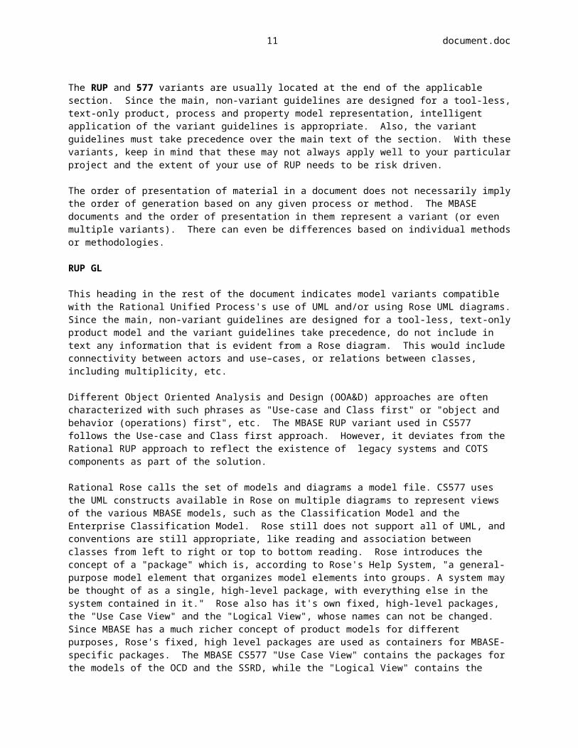


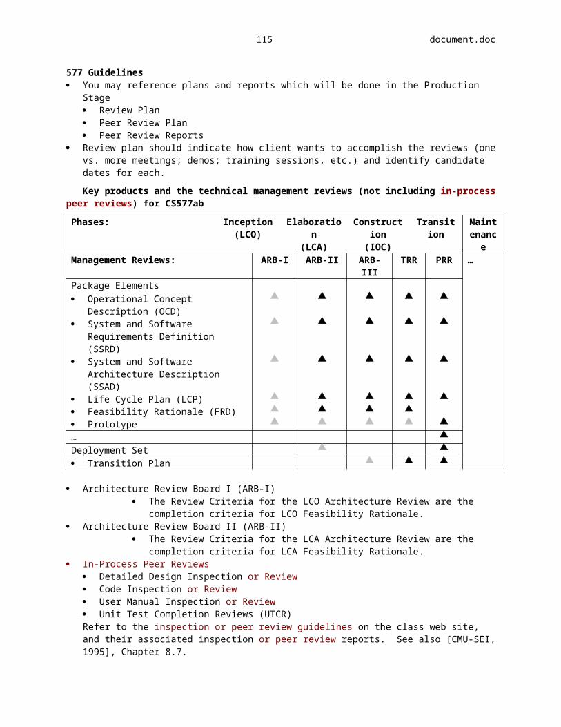


![interoperability.blob.core.windows.netinteroperability.blob.core.windows.net/.../[MS-OXRTFEX] … · Web viewThis protocol documentation is covered by Microsoft copyrights. Regardless](https://static.documents.pub/doc/80x56/5a79e8977f8b9a99188d4035/ms-oxrtfex-web-viewthis-protocol-documentation-is-covered-by-microsoft-copyrights.jpg)
![interoperability.blob.core.windows.netinteroperability.blob.core.windows.net/.../[MS-OXRTFCP] … · Web viewThis protocol documentation is covered by Microsoft copyrights. Regardless](https://static.documents.pub/doc/80x56/5af90fb37f8b9aac248df14c/ms-oxrtfcp-web-viewthis-protocol-documentation-is-covered-by-microsoft-copyrights.jpg)


