20
August, 2012 San Bernardino County Web Site: cms.sbcounty.gov

August, 2012 San Bernardino County Web Site: cms.sbcounty.gov

NOTE: Please be advised sections in this Guidelines booklet are subject to change without notification. Contact the Building and Safety Division if you have questions.
NOTICE TO MOUNTAIN AREA RESIDENTS
AN EROSION AND SEDIMENT CONTROL
ORDINANCE WHICH APPLIES TO YOUR
AREA, REQUIRES THE SUBMISSION OF AN
EROSION CONTROL PLAN FOR ANY
CONSTRUCTION WHICH INVOLVES A LAND
DISTURBING ACTIVITY. ALSO, SPECIAL
SNOWLOADS APPLY TO MOUNTAIN
CONSTRUCTION. CONTACT YOUR LOCAL
BUILDING AND SAFETY OFFICE FOR A COPY
OF THE SNOWLOAD RAFTERS/JOIST
FRAMING TABLE FOR YOUR SPECIFIC AREA.

COUNTY OF SAN BERNARDINO
BUILDING AND SAFETY DIVISION
This booklet provides general information necessary to
build or alter a dwelling in compliance with the San
Bernardino County Codes. Please contact any of our
offices for specific questions or additional information.
PERMITS: Permits are required to build, alter, repair,
move or demolish any building and to do electrical,
plumbing, heating, solar, and air conditioning work.
Earthwork grading and driveway approaches also require
permits. Permits may be obtained at your local Building
and Safety Office (listed on the inside of the back cover).
Be sure you have all the necessary permits before you
start work.
Prior to any construction and/or land disturbing activity,
obtain a Preconstruction Inspection or Erosion Control
Permit and request an on-site inspection of your lot in
order to obtain approval or clearance for subsequent
building permits. Some areas are within zones where
special studies may be needed. The specific requirements
for your project can be obtained from your local Building
and Safety office.
After the preconstruction or erosion control inspection is
approved and the building permit is issued, any
excavation that is less than two feet (2’) in depth or does
not create a cut slope greater than five feet (5’) in height
is exempt from a grading permit. Fills less than one foot
(1’) in depth or that do not exceed 50 cubic yards when
less than three feet (3’) in depth, not intended to support
structures and do not obstruct a drainage course are also
exempt from grading permits. Other grading projects not
exempt will require permits. To obtain a grading permit,
bring your grading plan into one of our offices for review.
You'll need plans prepared by a civil engineer if your job
is over 5,000 cubic yards. Stop by for an information
sheet describing when grading plans are required and the
features needed on them.
PERMIT FEES: Permit fees for residential buildings
and accessory buildings are based on the size of the
building being built. We will be happy to provide more
detailed fee information. There may be other fees, such
as school fees, traffic fees or drainage fees due in your
area. We can provide you with that information also.
ALTERATIONS AND ADDITIONS: If you intend to
add to or otherwise remodel a building, contact your local
Building and Safety office for a Prealteration Inspection
before you apply for the permit. There is no charge for
the prealteration inspection and it can help avoid
problems that might occur during construction.
MOVING PERMITS: When a building is moved, there
are a few additional steps in the application process. We
need two photos (one of the front) and a termite certificate
showing the building is free of termites. Be sure to bring
them in when you apply for the relocation inspection.
The permits for the location work can be obtained
anytime before the building is moved. Ask your local
office for a relocation application package.
PLANS: A set of plans includes a plot plan, foundation,
floor, framing and roof plans; elevations, sections, details,
specifications and energy information which consists of
an energy compliance package, heating and cooling
calculations and a list of mandatory features and devices.
More detailed requirements for a set of plans can be
obtained from any of our offices.
LEGAL DESCRIPTION: The legal description of your
lot or parcel is a part of the application to build and can be
found on your deed, title policy, escrow instructions or
contract of sale. Lot surveys are recommended and often
required. Your Assessor's Parcel Number is required in
addition to the legal description and needs to be written
on the application.
LOCATION ON PROPERTY: Yards are required
around all dwellings. The front yard and other yards
fronting on streets are determined by the width of the
right of way. Side yards vary with the zone, fire hazard
area and lot width. This information may be obtained at
one of our offices.
PARKING AND GARAGES: All dwellings need to
have two parking spaces. In most areas, those spaces and
the driveway to them are paved. A parking space is 9 feet
x 19 feet and at least one is required to be covered, (a
minimum of 10 feet x 20 feet) except in the mountain
areas. There are some exceptions that you may want to
check on.
The private garage shall be separated from the dwelling
unit and its attic area by means of a minimum ½-inch
gypsum board applied to the garage side. Garages
beneath habitable rooms shall be separated from all
habitable rooms above by not less than a 5/8-inch Type X
gypsum board or equivalent. Door openings between a
private garage and the dwelling unit shall be equipped
with either solid wood doors or solid or honeycomb core
steel doors not less than 1-3/8 inches (34.9 mm) thick.
Openings from a private garage directly into a room used
for sleeping purposes shall not be permitted. Doors shall
be self-closing and self-latching.
1

BUILDING SIZES: Residential structures located on
lots greater than thirty feet (30’) in width and greater than
five thousand (5,000) sq. ft. in area, require a minimum
living area of seven hundred twenty-five (725) sq. ft., with
a minimum floor width and depth each averaging twenty
feet (20’). All measurements are from the exterior of the
structure.
Residential structures located on lots of thirty feet (30’) or
less in width or five thousand (5,000) sq. ft. or less in
area, require a minimum living area of six hundred (600)
sq. ft., with a minimum floor width of fifteen feet (15’).
All measurements are from the exterior of the structure.
Some exceptions are allowed under our Alternate
Housing Standards, check with your local Building and
Safety Office to see if they apply.
ROOM SIZES: The main room in a dwelling needs to
have a minimum 120 sq. ft. of floor area. Other rooms
except kitchens need only be 70 sq. ft. in area exclusive of
cabinets or other built-ins. These rooms need not be
wider than 7 ft. A 30 in. wide compartment with 24 in. of
clear space in front of the toilet is necessary for a toilet
compartment.
CEILING HEIGHT: The ceiling in living rooms,
bedrooms and other habitable rooms is at least 7 ft. above
the floor including halls, laundries, kitchens and
storerooms. Bathrooms need only be 6 ft. 8 in. For
rooms with sloping ceilings, the code requires only that
the prescribed ceiling height be maintained in one-half the
area of the room. However, no portion of the room which
has a ceiling height of less than 5 feet shall be used in the
computations for minimum floor area. In the case of a
room with a furred ceiling, the code requires the
prescribed ceiling height in two thirds of the area and, as
in all cases for projections below the ceiling, the furred
area may not be less than 7 feet above the floor.
ATTIC ACCESS AND VENTILATION: In order to
get into the attic for repairs and maintenance, a 20 in. x 30
in. scuttle is required for attics 30 in. or more in height.
Enclosed attics and enclosed rafter spaces shall have cross
ventilation for each separate space by ventilated openings
protected against the entrance of rain and snow. A
minimum of 1” air space shall be provided between the
insulation and the roof sheathing. The net free ventilating
area shall not be less than 1/150 of the area of the space
ventilated. The required ventilation may be decreased to
1/300 provided a vapor retarder having a transmission rate
not exceeding 1 perm is installed. If the attic is used as a
source of combustion air for gas fired appliances refer to
the combustion air requirements under the heating and air
conditioning section in this booklet. Cover these
openings with rust resistant wire netting with ¼ inch mesh
or in the fire safety overlay areas, use 1/8” mesh.
WINDOWS: All habitable rooms need windows for
natural light. Kitchen and bathrooms are an exception
and may use artificial light. To determine the area of the
required windows, multiply the floor area of the room by
8% (0.08).
An exterior exit door out of a bedroom is not required if
one of the windows has a 20 in. wide openable area of at
least 5.7 sq. ft. The opening height needs to be at least 24
in. and the sill no more than 44 in. above the floor (the
two dimensions alone, 20 x 24, do not provide the
required 5.7 sq. ft. of openable area). See Table below.
If the sill height of the required net opening is no more
than 44” above or below the finish grade, a 5.0 sq. ft. net
opening is allowed.
MINIMUM NET CLEAR OPENING TABLE
FOR ESCAPE/RESCUE WINDOWS
NET WIDTH X NET HEIGHT = TOTAL SQ. FT.
20” min. X 41¼“ = 5.73
21” X 39¼“ = 5.72
22” X 37½“ = 5.73
23” X 36¾“ = 5.72
24” X 34¼“ = 5.71
25” X 33” = 5.73
26” X 31¾“ = 5.73
27” X 30½“ = 5.72
28” X 29½“ = 5.74
29” X 28½“ = 5.74
30” X 27½“ = 5.73
31” X 26½“ = 5.70
32” X 25¾“ = 5.72
33” X 25” = 5.73
34¼“ X 24” min. = 5.71
NET WIDTH X NET HEIGHT = TOTAL SQ. FT.
Ventilation may be by either mechanical or natural means.
To determine the area of openable exterior openings for
natural ventilation, multiply the floor area of each room
by 4% (0.04). (See above for bedroom exits.) For
mechanical ventilation, provide a system that will
completely change the air in each room every 30 minutes,
with a minimum of 15 cubic feet per minute of outside air
per occupant in dwellings (the occupant load of a
dwelling will be based on 200 sq. ft. per occupant). For
bathrooms, the minimum opening is 4% of the floor area.
Manually switched mechanical ventilation for bathrooms
shall be exhaust ventilated with at least 50 cubic foot per
minute to the outside.
STAIRWAYS: Stairs in dwellings need only be 36 in.
wide. The height of the risers should not exceed 7 ¾ in.
and the tread should be at least 10 in. Open sides of
stairways and landings more than 30 in. above floor or
grade below require guards with balusters or ornamental
patterns such that a 4-inch-diameter sphere cannot pass
through any opening. On landings and balconies guards
shall be 42 in. high and on stairs 34 to 38 in. high.
2

Openings for required guards on the sides of stair treads
shall not allow a sphere of 4.375 inches (4 3/8”) to pass
through. It can also serve as the handrail for stairs if the
top rail has an approved gripping surface. The headroom
clearance, measured vertically from the nosings of the
treads, must be at least 6 ft. 8 in.
FIRE SPRINKLER REQUIREMENTS
R313.2 One- and two-family dwellings automatic fire
systems. An automatic residential fire sprinkler system
shall be installed in one- and two-family dwellings.
Exception: An automatic residential fire sprinkler
system shall not be required for additions or
alterations to existing buildings that are not already
provided with an automatic residential sprinkler
system.
R313.2.1 Design and installation. Automatic residential
fire sprinkler systems shall be designed and installed in
accordance with Section R313.3 or NFPA 13D.
R313.3 Dwelling Unit Fire Sprinkler Systems.
R313.3.1 General. Where installed, residential fire
sprinkler systems, or portions thereof, shall be in
accordance with NFPA 13D or Section R313.3, which
shall be considered equivalent to NFPA 13D. Section
R3313.3 shall apply to stand-alone and multi-purpose
wet-pipe sprinkler systems that do not include the use of
antifreeze. A multipurpose fire sprinkler system shall
supply domestic water to both fire sprinklers and
plumbing fixtures. A stand-alone sprinkler system shall
be separate and independent from the water distribution
system. A backflow flow preventer shall not be required
to separate a stand-alone sprinkler system from the water
distribution system.
FIRE WARNING SYSTEMS: To warn you when a fire
starts while you are sleeping, an approved smoke detector
with an audible alarm is required. Install the detectors in accordance with the approved manufacturer’s instructions. Locate the detectors in each bedroom, in the
hallway or area leading to bedrooms, in basements, and at
least one on each floor. When bedrooms are above the
first floor, a detector is required to be placed at the ceiling
of the upper level in close proximity to the stairway.
Other conditions such as ceilings of different height
require special treatment. Contact us for these additional
requirements.
CARBON MONOXIDE ALARMS
R315.1 CARBON MONOXIDE ALARMS: For new
construction, an approved carbon monoxide alarm shall
be installed in dwelling units and in sleeping units within
which fuel-burning appliances are installed and in
dwelling units that have attached garages.
FIRE SAFETY OVERLAY AREAS: In high fire
hazard areas, there are special requirements for roofing
and exterior construction. Check with us to see if your
property is located in one of these designated areas. The
Fire Department may place conditions on the
construction. A Fire Department Project Condition Letter
is required for most construction activity.
ENERGY CONSERVATION: Energy conservation
standards have been established by the State. Due to the
climatic extremes in our County, there are no typical
designs which would apply to all locations. The standards
for insulation, windows and orientations will vary
according to the compliance approach chosen as well as
the climate zone. Contact any of our offices for
clarification of the minimum information necessary for
compliance.
Mandatory features for all residential buildings:
1. Weather-strip exterior doors and windows.
2. Caulk and seal joints and penetrations to
unconditioned areas.
3. Manufactured doors and windows to be certified and
labeled.
4. Exhaust fans need damper controls.
5. For fireplaces:
a) Tight-fitting, closeable metal or glass door(s).
b) Outside air intake with dampers and controls in
fireplaces located on the outside walls or over
wood floors.
c) Flue dampers and controls.
d) No continuous burning gas pilots.
6. Vapor barriers in Upper Desert and Mountain areas.
7. Insulate heating and air conditioning ducts.
8. Automatic setback thermostats for heating and
cooling system.
9. Wrap storage type water heater and storage and
backup solar water heaters with R-12 insulation.
10. Insulate the first 5 feet of hot and cold water pipes
closest to the water heater with R-12 insulation.
11. Gas cooking appliances equipped with intermittent
ignition devices.
12. Use fluorescent fixtures or another approved energy
saving means for all lighting.
13. Slab edge insulation should be water and vapor
resistant.
14. Heating and air conditioning equipment, water
heaters, shower heads and faucets to be certified by
the California Energy Commission (CEC).
15. Insulation to meet CEC standards and be listed.
3

NOISE INSULATION: Noise insulation is necessary in
the floors and walls between various units in multiple
family dwellings. Contact us for detailed requirements.
WOOD FRAME CONSTRUCTION
SITE PREPARATION AND FOUNDATIONS: In
order to protect your building from termites, be sure that
all roots, stumps, wood forms and wood scraps are
removed from under the building to a depth of 12 in.
below the ground.
A continuous concrete foundation is needed for bearing
walls. See the framing detail provided on page 5 for size
and framing attachment. If your lot slopes more than 1 ft.
in 10 ft., the foundation should be stepped with the top
and bottom level.
CONCRETE MIX: When ordering ready-mix concrete
specify at least 2500 psi concrete. When mixing your
own, use 1 and 1/3 sacks of cement to 3 cu. ft. of sand and
4 cu. ft. of crushed rock or gravel.
UNDERFLOOR VENTILATION AND ACCESS:
Areas under the first floor of a wood frame house need
cross ventilation openings on at least two (2) opposite
sides of the building. The total area in square feet of all
openings needs to be 1 sq. ft. for each 150 sq. ft. of
underfloor area. Cover these openings with rust-resistant
wire netting with ¼ inch mesh or in the fire safety overlay
areas, use 1/8” mesh. An 18 in. x 24 in. access can be
either through the floor or through the outside wall.
MUDSILLS: Foundation plates and other members in
contact with the foundation are to be either approved
treated lumber or foundation grade redwood.
FOUNDATION STUDS: Foundation studs 14 in. or
less in height can be the same size as the studs above.
When over 14 in. they are to be sized as for an additional
story. Studs less than 14 inches in height are to be braced
by solid blocking or structural wood panel sheathing.
GIRDERS: Floor joists may be supported on girders
with piers. Girder ends resting on concrete requires 3 in.
bearing and if in a girder pocket, provide ½ in. air space at
the tops, sides and end.
FLOOR JOISTS: Floor joists bearing on sills and
girders shall have 1½ in. of bearing. Be sure to lap them
3 in. and nail to the joist coming from the other side.
If a header joist is over 4 ft. long, it and the trimmer joists
are required to be doubled. Use joist hangers when the
header joist is over 6 ft. long and/or when the tail joists
are over 12 ft. long.
To prevent floor joists from turning, the ends are required
to be blocked solid. Also block them at each support.
Be sure to double the joists under and parallel to bearing
walls. Bearing walls perpendicular to the joist do not
have to line up exactly with the wall or beam below as
long as they are not more than one (1) joist depth offset.
WALLS AND PARTITIONS: The top plate on a frame
wall should be doubled to tie all the walls in the building
together. This is done by lapping all the corners and
intersections and by lapping splices at least 4 feet. These
plates also serve as fireblocks. Other places still need
fireblocks. Some of them are between the studs in line
with stair stringers, at the top and bottom riser, at dropped
ceilings, bay windows and raised floors.
Openings for windows and doors are allowed in bearing
walls if the load above them is supported by a properly
sized header. A king stud and trimmer is needed at each
end of the header.
BRACING: Your home must be constructed with
adequate bracing to resist wind and seismic forces.
Braced wall panels are required at each corner and along
the building perimeter, not more than 25 ft. end to end.
To meet this requirement, typical light-frame construction
usually incorporates plywood braced wall panels on
exterior walls. 1” x 4” diagonal braces are no longer
considered adequate bracing for wind and seismic forces
in San Bernardino County. Refer to the “Guide to
Conventional Light Frame Bracing” or contact us for
additional information on braced wall panel requirements
and options.
WALLS AND PARTITIONS TABLE
SIZE, HEIGHT AND SPACING OF WOOD STUDS1
BEARING WALLS
NONBEARING
WALLS
STUD
SIZE
(Inches)
LATERALLY
UNSUPPORTED
STUD
HEIGHT3
(Feet)
SUPPORTING
ROOF AND
CEILING
ONLY
SUPPORTING
ONE FLOOR,
ROOF AND
CEILING
SUPPORTING
TWO FLOORS,
ROOF AND
CEILING
LATERALLY
UNSUPPORT
ED
STUD
HEIGHT3
(Feet)
SPACING
(Inches)
SPACING (Inches)
1. 2x32 10 16
2. 2x4 10 24 16 14 24
3. 3x4 10 24 24 16 14 24
4. 2x5 10 24 24 16 24
5. 2x6 10 24 24 16 20 24
1Utility grade studs shall not be spaced more than 16 inches on
center, nor support more than a roof and ceiling, nor exceed 8 feet
in height for exterior walls and load bearing or 10 feet for interior
nonload-bearing walls. 2Shall not be used in exterior walls. 3Listed height are distances between points of lateral support placed
perpendicular to the plane of the wall. Increases in supported height
are permitted where justified by an analysis.
4 4

MECHANICAL FASTENERS:
Connections depending upon joist hangers or framing
anchors, ties and other mechanical fastenings may be
used where approved.
ROOF CONSTRUCTION: Hips, valleys and ridges
are required to be one size larger than the common
rafters. Ridge board may be 1 in. nominal thickness.
Since valleys are about the weakest point in the roof
they need special attention to bracing.
When the roof slope is less than 3:12, members
supporting rafters and ceiling joists such as ridges, hips
and valleys are required to be designed as beams.
Roofing materials are to comply with Cool Roof
Requirements per the California Energy Code (CEC).
5

6
3) Where the slab is not cast monolithically with the footing, No. 3 or larger vertical dowels with standard hooks on each end shall be provided. Ask for detail from Figure R403.1.3.2 and R611.5.4.5 of the 2010 California Residential Code.

RAFTER AND JOIST TABLES - VALLEY AND DESERT AREAS (no snow loads)
These tables are based on Douglas Fir or Larch lumber of No. 2 grade. Roofing material such as rock, gravel, tile or shake shingles are heavy roofs. Composition
shingles and wood shingles are light roofs. High slope roofs are those with a slope greater than 3 inches in 12 inches. The spans are the clear horizontal distance
between supports, in feet and inches. Cantilevered rafters have a 1½ in. notch. If you are in a snow area, obtain a Snow Load Table for your area.
2 x RAFTERS 4 x RAFTERS
ALL SLOPES LOW SLOPES HIGH SLOPES Size Spacing Span Cantilevered
With Drywall Ceiling 4 x 4 24 10-4 -
Size Spacing Light Heavy Cantilevered Light Heavy Light Heavy 32 9-1 -
2 x 4 12 9-10 9-9 2-7 9-10 9-10 10-7 10-7 36 8-7 -
16 8-11 8-5 2-4 8-11 8-11 9-7 9-7 48 7-5 -
24 7-4 6-11 2-1 7-9 7-4 8-4 7-10
4 x 6 24 16-3 3-11
2 x 6 12 15-4 14-4 5-3 15-5 15-4 16-7 16-3 32 13-4 3-2
16 13-3 12-5 4-9 14-0 13-3 15-1 14-1 36 12-7 3-0
24 10-10 10-1 3-11 11-8 10-10 12-7 11-6 48 10-11 2-5
2 x 8 12 19-5 18-2 7-7 20-4 19-5 21-11 20-7 4 x 8 24 21-5 5-8
16 16-10 15-8 6-8 18-2 16-10 19-6 17-10 32 17-7 4-7
24 13-8 12-10 5-5 14-10 13-8 15-11 14-7 36 16-7 4-3
48 14-4 3-9
2 x 10 12 23-9 22-2 9-11 25-7 23-9 26-0 25-2
16 20-6 19-2 8-7 22-2 20-6 23-10 21-10 4 x 10 24 26-0 7-4
24 16-9 15-8 7-0 18-1 16-9 19-5 17-10 32 21-7 5-11
36 20-4 5-7
2 x 12 12 26-0 25-9 11-11 26-0 26-0 26-0 26-0 48 17-7 4-10
16 23-10 22-3 10-4 25-9 23-10 26-0 25-4
24 19-5 18-2 8-5 21-0 19-5 22-7 20-8 4 x 12 24 26-0 8-10
32 25-2 7-1
36 23-9 6-9
48 20-6 5-10
CEILING JOISTS
W/O STORAGE
PATIO RAFTERS 2 x FLOOR JOISTS 4 x FLOOR JOISTS
Light Aluminum or Other
(40 lb. Live Load) (40 lb. Live Load)
Size Spacing Span Size Spacing Fiberglass Roofs Size Spacing Span Cantilevered Size Spacing Span Cantilevered
2x4 12 12-5 2x4 16 8-7 8-2 2x6 12 10-8 4-4 4x6 24 11-3 4-7
16 11-3 24 7-11 7-4 16 9-8 4-0 32 10-0 4-2
24 9-10 32 6-11 6-3 24 8-1 3-5 36 9-5 3-11
48 8-2 3-5
2 x6 12 19-6 2x6 16 14-7 13-7 2x8 12 14-1 5-9
16 17-8 24 13-2 12-0 16 12-7 5-3 4x8 24 14-10 6-1
24 14-10 32 11-1 9-10 24 10-3 4-4 32 13-2 5-6
36 12-5 5-3
2x8 12 25-8 2x8 16 20-0 18-6 2x10 12 17-9 7-4 48 10-9 4-6
16 23-0 24 17-11 15-10 16 15-4 6-5
24 18-9 32 14-7 12-11 24 12-6 5-3 4x10 24 18-11 7-9
32 16-2 6-10
2x10 12 26-0 4x4 16 12-1 11-3 2x12 12 20-7 8-8 36 15-3 6-5
16 26-0 24 10-11 10-2 16 17-9 7-6 48 13-2 5-7
24 22-11 32 10-2 9-4 24 14-6 6-1
4x12 24 23-1 9-5
2x12 12 26-0 32 18-10 7-11
16 26-0 36 17-9 7-6
24 26-0 48 15-4 6-6
VALLEY / MOUNTAIN PLYWOOD ROOF SHEATHING ALLOWABLE UNIFORM ROOF LIVE LOADS FOR APA RATED SHEATHING WITH LONG DIMENSION PERPENDICULAR TO SUPPORTS
1, 2
APA RATED SHEATHING ROOF
SPAN RATING PANEL THICKNESS MAXIMUM SPAN (Inches) ALLOWABLE LIVE LOADS (psf)
With Edge Without Edge Spacing of Supports Center-to-Center (Inches)
Roof/Floor Span (Inch) Support3 Support 12 16 20 24 32 40 48 54 60
12/0 5/16 12 12 30
16/0 5/16, 3/8 16 16 70 30
20/0 5/16, 3/8 20 20 120 50 30
24/0 3/8, 7/16, 1/2 24 204 190 100 60 30
24/16 7/16, 1/2 24 24 190 100 65 40
32/16 15/32, 1/2, 5/8 32 28 325 180 120 70 30
40/20 9/16, 19/32, 5/8, 3/4, 7/8 40 32 305 205 130 60 30
48/24 23/32, 3/4, 7/8 48 36 280 175 95 45 35
54/32 7/8, 1 54 40 245 130 75 50 35
60/32 7/8, 1 60 40 305 165 100 70 50 35
60/48 7/8, 1, 1-1/8 60 48 305 165 100 70 50 35
1
The allowable live loads were determined using a dead load of 10 psf. If the dead load exceeds 10 psf then the live load shall be reduced accordingly. 2
Applies to panels 24 inches or wider. 3
Tongue-and-groove edges, panel edge clips (one midway between each support, except two equally spaced between supports 48 inches on center), lumber blocking, or other. Only lumber blocking will satisfy blocked
diaphragm requirements. 4
Twenty-four inches for 1/2 inch panels.
7
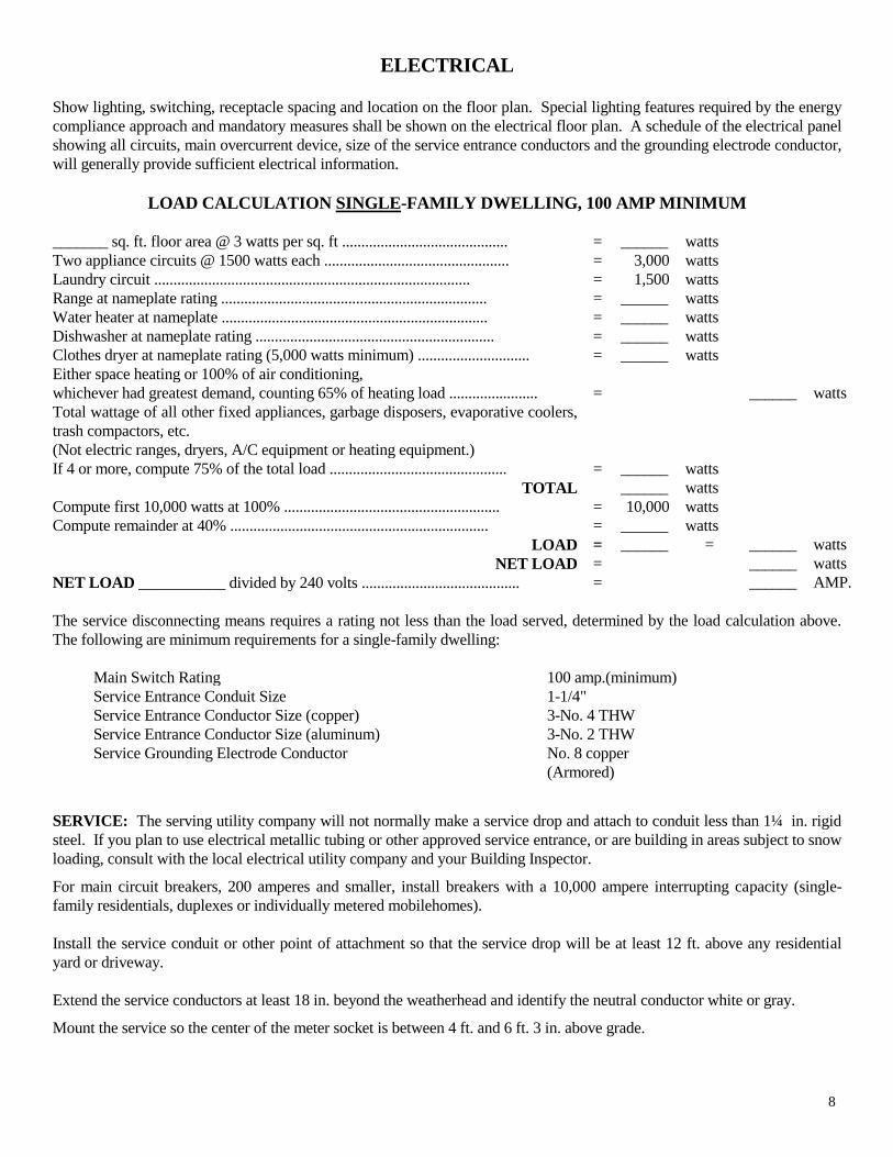
ELECTRICAL Show lighting, switching, receptacle spacing and location on the floor plan. Special lighting features required by the energy
compliance approach and mandatory measures shall be shown on the electrical floor plan. A schedule of the electrical panel
showing all circuits, main overcurrent device, size of the service entrance conductors and the grounding electrode conductor,
will generally provide sufficient electrical information.
LOAD CALCULATION SINGLE-FAMILY DWELLING, 100 AMP MINIMUM
_______ sq. ft. floor area @ 3 watts per sq. ft ........................................... = ______ watts
Two appliance circuits @ 1500 watts each ................................................ = 3,000 watts
Laundry circuit .................................................................................. = 1,500 watts
Range at nameplate rating ..................................................................... = ______ watts
Water heater at nameplate ..................................................................... = ______ watts
Dishwasher at nameplate rating .............................................................. = ______ watts
Clothes dryer at nameplate rating (5,000 watts minimum) ............................. = ______ watts
Either space heating or 100% of air conditioning,
whichever had greatest demand, counting 65% of heating load ....................... = ______ watts
Total wattage of all other fixed appliances, garbage disposers, evaporative coolers,
trash compactors, etc.
(Not electric ranges, dryers, A/C equipment or heating equipment.)
If 4 or more, compute 75% of the total load .............................................. = ______ watts
TOTAL ______ watts
Compute first 10,000 watts at 100% ........................................................ = 10,000 watts
Compute remainder at 40% ................................................................... = ______ watts
LOAD = ______ = ______ watts
NET LOAD = ______ watts
NET LOAD ___________ divided by 240 volts ......................................... = ______ AMP.
The service disconnecting means requires a rating not less than the load served, determined by the load calculation above.
The following are minimum requirements for a single-family dwelling:
Main Switch Rating 100 amp.(minimum)
Service Entrance Conduit Size 1-1/4"
Service Entrance Conductor Size (copper) 3-No. 4 THW
Service Entrance Conductor Size (aluminum) 3-No. 2 THW
Service Grounding Electrode Conductor No. 8 copper
(Armored)
SERVICE: The serving utility company will not normally make a service drop and attach to conduit less than 1¼ in. rigid
steel. If you plan to use electrical metallic tubing or other approved service entrance, or are building in areas subject to snow
loading, consult with the local electrical utility company and your Building Inspector.
For main circuit breakers, 200 amperes and smaller, install breakers with a 10,000 ampere interrupting capacity (single-
family residentials, duplexes or individually metered mobilehomes).
Install the service conduit or other point of attachment so that the service drop will be at least 12 ft. above any residential
yard or driveway.
Extend the service conductors at least 18 in. beyond the weatherhead and identify the neutral conductor white or gray.
Mount the service so the center of the meter socket is between 4 ft. and 6 ft. 3 in. above grade.
8

GROUNDING AND BONDING: The 100 amp. service
ground may be No. 8 if armored or in conduit, or No. 6
bare if it follows closely along the building finish.
Use a UL listed ground clamp to attach the grounding
electrode conductor to an approved electrode in a location
which will remain accessible without crawling when the
building is completed.
Where aluminum grounding conductors are used, install
one (1) size larger than required for copper and maintain
at least 18 in. above ground. Provide protection for any
aluminum grounding conductor run through stucco or
concrete.
When using a metallic water service for the service
ground, supplement it with an additional electrode.
Contact your local Building Inspector for information on
the "UFER" (concrete encased) electrode before placing
your foundation.
Bond interior water and gas piping to the grounding
conductor’s terminal at the service. Isolate neutral wires
from the bond wires in subpanels in the same building.
All subpanels require bonding back to the main panel
ground. Contact the building inspector for details of
subpanels installed in separate buildings.
WORKING SPACE: Maintain at least a 30 in. wide x
36 in. deep work space in front of the electrical service
equipment.
WIRING: Use approved raintight equipment in exposed
areas outside of a building.
If nonmetallic sheathed cable is installed in exposed
locations it must be run on the inside edge of framing
members. Provide running boards at any location where
cables are subject to damage. (See Article 300 of the
NEC for additional wiring requirements.)
Neutral conductors No. 6 and smaller require white or
gray insulation along their entire length. Conductors No.
4 or larger may be identified where terminating in
enclosures with a white or gray color paint or tape.
When the white wire in nonmetallic sheathed cable is
used as a hot wire, as in a 240-volt circuit, identify the
conductor red or black where it is visible.
Install a properly sized outlet or junction box at each
outlet, switch or junction point. A junction box may be
installed in an attic where there is at least 30 in. of
headroom.
Leave at least 6 in. of "make-up" wire at each outlet
(receptacle, switch, fixture or junction box).
Use nonmetallic sheathed cable with 15 or 20 and 30
ampere capacity circuits with a grounding conductor of
the same size as the circuit conductors. For cable with 40 and 60 ampere capacity, the grounding conductor needs to
be 30 ampere capacity.
For lighting or convenience outlet circuits, install wiring
with a minimum 15 ampere capacity (No. 14 copper).
Install at least two small appliance circuits, rated at 20
amperes each, in the kitchen/dining area (No. 12 copper).
Provide separate circuits for garbage disposals, trash
compactors and dishwashers. Their recommended circuit
ampacities are 15, 15 and 20 amperes respectively.
Provide receptacles at any wall space 2 ft. or more in
width in livable rooms, including the wall space occupied
by fixed panels (i.e. fixed panel of sliding glass door) in
exterior walls, so that no point on any wall is over 6 ft.
from an outlet in that space (one receptacle every 12 ft).
Include fixed room dividers or free-standing bar-type
counters in the 6 ft. measurement. In kitchen and dining
areas, install a receptacle at each counter space 12 in. or
wider. Any outlet rendered inaccessible by the
installation of stationary appliances, including
refrigerators, are not counted as one of these required
receptacles. Any receptacle which is part of a fixture or
appliance, or is located over 5½ ft. above the floor, is
also not counted as one of the required outlets.
All branch circuits that supply 125-volt, single phase, 15-
and 20-ampere outlets in dwelling unit family rooms,
dining rooms, living rooms, parlors, libraries, dens,
bedrooms, sunrooms, recreation rooms, closets, hallways
or similar rooms or areas are required to be protected by
an ARC-Fault Circuit Interrupter (AFCI) type circuit
breaker.
All 125-volt, single-phase, 15 and 20 ampere receptacles
installed to serve kitchen counter top surfaces need
ground-fault circuit-interrupter (GFCI) protection for
personnel.
Install receptacles within 36 in. to each washbasin, in each
basement, attached garage, detached garages with electric
power and at least one receptacle in hallways 10 ft. or
more in length and one exterior receptacle at the front and
rear of one and two family dwellings.
Install grounding-type receptacles throughout. Ground-
fault circuit-interrupters (GFCI) are required for all
receptacles located outdoors, in crawl spaces under
building, in kitchens and bathrooms, within 6 ft. of wet
bar, laundry and utility sinks and for the required
convenience work with receptacles in garages.
9

LIGHTING OUTLETS: Provide lighting outlets as
follows:
At least one (1) wall-switch controlled light in every
habitable room, hallway, stairway, attached garage,
detached garage with electric power, bathrooms, and at all
outdoor entrances. A wall-switched receptacle in lieu of a
lighting outlet is permitted in all habitable rooms except
kitchens and bathrooms. Install at least one (1) lighting
outlet in the attic, underfloor space, utility room or
basement suitable for storage or if it contains equipment
which requires service.
Lighting fixtures maintaining at least a 12 in. horizontal
clearance in clothes closets from any area where
combustible material may be stored is a proper
installation (storage shelf area is considered to continue
vertically to the closet ceiling). A flush recessed fixture
with a solid lens or ceiling mounted fluorescent fixture
requires 6 in. horizontal clearance from any area where
combustible materials may be stored. Incandescent
fixtures with open or partially enclosed lamps and
hanging lights (pendant fixtures) are not allowed in
clothes closets.
LAUNDRY AND BATHROOM CIRCUITS: Provide
separate 20 ampere circuits for laundry and bathroom
receptacle outlets. If there is only one (1) receptacle on
the circuit, install a 20 ampere rated receptacle.
OUTLET/JUNCTION BOXES: Plastic boxes are
usually marked on the inside with their volume (in cubic
inch capacity) along with the maximum number and size
of conductors allowed in the box.
CENTRAL HEATING EQUIPMENT: Central heating
equipment requires an individual branch circuit sized per
the manufacturer’s installation instructions.
Use the following table and rules to size plastic or metal
boxes that are not marked with their volumes and number
of conductors allowed.
AREA REQUIRED FOR EACH
CONDUCTOR IN OUTLET BOXES
A.W.G. Free Space For
Size Each Conductor #18 1.5 cu. in.
#16 1.75 cu. in.
#14 2 cu. in.
#12 2.25 cu. in.
#10 2.50 cu. In.
# 8 3 cu. in.
# 6 5 cu. in.
Add the area of two (2) conductors for the following:
Each yoke or strap containing one or more devices
(switch or receptacles) mounted in the box. (The
free space will be based on the largest conductor
connected to the device.)
Conductors spliced together (with wire nuts, etc.).
Add the area of one (1) conductor for the following:
Each type of fixture stud, hickey, or cable clamp.
The free space will be based on the largest
conductor entering the box. (Romex connectors
attached to the outside of the box do not count.)
One or more equipment grounding conductors (the
free space will be based on the largest equipment
grounding conductor entering the box).
Isolated equipment grounding conductors.
Unspliced conductors running through the box.
Each conductor originating outside of the box and
terminating inside the box.
No additional area required for the following:
Maximum 4 fixture wires not larger than No. 16
plus ground from fixture canopy.
Conductors that do not leave the box.
Make sure all work is inspected and passed by the
Building Inspector before concealing.
Your local Building Inspector is prepared to assist you
with any construction questions that may arise.
HEATING AND AIR CONDITIONING
ACCEPTANCE: Appliances are designed for the use of
a particular type of fuel. Be sure they are only connected
to the type of fuel specified on the label. Some appliances
can be converted to use another fuel provided it is
re-labeled to indicate that such a conversion has been
made.
GAS-FIRED WATER HEATERS: Water heaters are
allowed in their own closet in a bedroom or bathroom if it
is a direct vent type water heater or the closet has a
gasketed self-closing door and all the combustion air
comes from outdoors. Water heater installations are
routinely made with a minimum 3/4 in. cold water supply
line and a 3/4 in. gate valve installed ahead of the
transition connection. (See illustration on next page for
earthquake anchorage requirements).
10

VENTING AND VENT CONNECTORS: Typically,
gas-fired appliances, such as water heaters and
blower-type warm air furnaces, are vented using type "B"
venting materials which are listed, generally by
Underwriters Laboratory (UL) and are installed with not
less than the minimum clearances indicated in the label.
When single-wall vent connector material is used for
connecting a gas-fired appliance to a type "B" vent, a
minimum of 6 in. from combustibles is maintained for the
connector installation.
CONDENSING FURNACES: A plastic pipe venting
system which is an integral part of a listed condensing
appliance shall be installed in accordance with the
appliance listing, manufacturer's installation instructions
and applicable local requirements. Provide the instruction
booklet with the unit when calling for inspection.
BLOWER-TYPE WARM AIR FURNACES: Warm
air furnaces are not allowed to be installed in a room used
or designed to be used as a bedroom, bathroom or clothes
closet. Furnaces may be installed in a closet located in
the bedroom or bathroom provided combustion air is
obtained from outdoors and the closet is equipped with a
listed, gasketed door assembly and a listed, self closing
device. Furnaces installed in attics and under floor spaces
may have access through a closet. For conventional
installations, (as illustrated on the next page) the room or
space is 12 in. wider than the furnace(s). Provide clear
spaces of 3 in. along the sides and back of the furnace
with 6 in. in front when the access door is closed.
Sufficient working space, generally not less than 30 in. in
the least dimension is provided along the entire front or
firebox side of the furnace when the door of the furnace
enclosure is fully opened.
11
1

NOTES:
1. Combustion Air: One-half within 12” of ceiling and one-half within 12” of floor.
2. Ducts:
Supply and Return — Insulated galv. steel or approved equal, or approved factory made airducts.
Combustion Air — Galv. steel — 26 gauge. Unlined stud and joist spaces also permitted, provided:
a. Not more than one required fire stop is removed.
b. The space used forms a continuous sealed air passage to the opening into the compartment.
3. Front Working Space: 30” in front of furnace when door is open.
4. Vent: U. L. approved type “B” gas vent.
5. Vent Connector: Galv. Steel
To 5” diameter ................. .28 ga. min.
5” to 9” diameter ...........…26 ga. min.
6. Clearances: Manufacturer’s recommended clearances shall apply when greater than those shown.
WATER HEATER ANCHORAGE REQUIREMENTS
The California Plumbing Code requires water heaters to be anchored for earthquakes. One of the following methods shall be deemed
to meet that requirement:
A. Anchor the water heater to an
adjacent wall with a minimum
of two, one inch wide, 18
gauge, galvanized steel straps.
Straps to be within the upper
one-third (1/3) and lower one-
third (1/3) of the water heater.
At the lower point, a
minimum distance of four (4)
inches shall be maintained
above the controls with the
strapping. Provide a two inch
long by 1/4 inch diameter lag
screw at each end of each
strap. The lag screws shall
penetrate a minimum of one
and one quarter inches into a
minimum two by four framing
member in the adjacent wall.
B. Where there is no solid
construction for attaching the
straps, a 4 x 4 redwood post or
equal shall be imbedded in a
concrete foundation, (minimum
twelve inch diameter by three
feet in depth). The length of post
shall equal at least the height of
the water heater after the
imbedment. And the straps shall
then be anchored to the post (see
adjacent illustration).
C. Other method(s), when found
to be equal.
12

COMBUSTION AIR TO FUEL-BURNING
APPLIANCES: Insufficient oxygen for combustion will
result in the formation of carbon monoxide. This gas is
poisonous and, if it remains within a building, it can cause
illness or even death to the occupants. Incomplete
combustion can also cause soot to build up in the heat
exchanger, flues, and vents.
Energy conservation regulations now require that
buildings be more tightly sealed, weather stripped, and
insulated to avoid infiltration of outside air to the interior
of the building. It is, therefore, more essential than it used
to be to make accurate calculations and adequate
provision for the supply of air to fuel-burning appliances.
Combustion air ducts must be constructed to allow an
unrestricted flow of air and to prevent the spread of fire
and the entry of foreign material and living creatures into
the building. Caution must be exercised to void negative
pressures that can be created by exhaust fans or the
natural draft of large appliances. If smaller appliances are
located in the same room, air will flow downward through
the vents or flues, carrying poisonous flue gas into the
room. The vents, flues, and combustion air ducts must be
adequately sized to maintain atmospheric pressure and
adequate ventilation for combustion.
The following are methods of supplying the required
combustion air.
ALL AIR SUPPLIED FROM INDOORS: The volume
of the room or space must be at least 50 cu. ft. per 1,000
btu input rating of all appliances in the room or space.
Rooms or spaces that communicate through at least two
fixed openings, each of which are a minimum of 1 sq. in.
per 1,000 btu input rating of all appliances in the room but
not less than 100 sq. in. and that are within 12” of the top
and bottom of the enclosure may be counted as part of the
required volume.
ALL AIR SUPPLIED FROM OUTDOORS: Two
Openings, within 12” of the top and bottom of the
enclosure that communicate directly or through ducts with
the outdoors sized as follows: Vertical ducts – 1 sq. in.
per 4,000 btu input rating of all equipment in the
enclosure. Horizontal ducts – 1 sq. in. per 2,000 btu input
rating of all equipment in the enclosure.
OR
One opening, within 12” of the top of the enclosure that
communicates directly or through a duct with the
outdoors that is 1 sq. in. per 3,000 btu input of all
equipment in the enclosure and not less than the total area
of all vent connectors in the space. The equipment must
have clearances of 1” min. from the sides and back and 6”
in the front.
COMBINATION INDOOR AND OUTDOOR
COMBUSTION AIR: When indoor openings are sized
and located as in “all air supplied from indoors” and
adequate volume does not exist, additional openings to
obtain combustion air from the outside are required. The
size of the outdoor openings are located as in “all air
supplied from outdoors” but is calculated as follows:
1. The ratio of interior spaces shall be the available
volume of all communicating spaces by fixed
openings divided by the required volume.
2. The outdoor size reduction factor shall be 1
minus the ratio of interior spaces.
3. The minimum size of outdoor openings shall be
the full size of outdoor openings calculated in
accordance with the size requirements above and
multiplied by the reduction factor. The minimum
dimension of air openings shall not be less than
3”.
COMBINATION INDOOR AND OUTDOOR AIR
EQUATION:
A = X 1 - X =Reduction Allowed
R
A = Cubic Feet Available.
R = Cubic Feet Required.
Combustion air ducts shall comply with the following:
1. Ducts shall be of galvanized steel or a material
having equivalent corrosion resistance, strength,
and rigidity.
Exception: Within dwelling units, unobstructed
stud and joist spaces shall not be prohibited from
conveying combustion air, provided that not more
than one fireblock is removed.
2. Ducts shall terminate in an unobstructed space,
allowing free movement of combustion air to the
appliances.
3. Ducts shall serve a single space.
4. Ducts shall not service both upper and lower
combustion air openings where both such
openings are used. The separation between ducts
serving upper and lower combustion-air openings
shall be maintained to the source of combustion
air.
5. Ducts terminating in attics shall not be screened.
13

6. Intakes for combustion-air ducts located exterior
to the building shall have the lowest side of the
combustion-air intake openings located at least
twelve (12) inches vertically from the adjoining
grade level.
7. Horizontal upper combustion-air ducts shall not
slope downward toward the source of combustion
air.
8. The remaining space surrounding a chimney
liner, gas vent, special gas vent, or plastic piping
installed within a masonry chimney flue metal or
factory-built chimney shall not be used to supply
combustion air unless it is listed and shown in the
manufacturer’s installation instructions.
9. Where not otherwise prohibited, the combustion
air supply may be obtained from an attic area
provided:
A. Attic ventilation if properly sized is
sufficient to provide the required volume
of combustion air.
B. The combustion air opening is provided
with a galvanized sleeve of not less than
No. 26 gauge extending from the
appliance enclosure to at least 6 in. above
the top of the ceiling joists and
insulation. (See illustration on page 11).
AIR RETURN: Circulating air may be taken from
outside the building, from rooms used for living quarters
or from both. The minimum unobstructed total area of the
circulating-air opening or ducts to a heat pump is 6 sq. in.
per 1,000 Btu/h nominal output rating or as indicated by
the conditions of listings of the heat pump. The minimum
unobstructed total area of the circulating air openings or
ducts to a blower-type warm air furnace is never less than
two (2) sq. in. for every 1,000 Btu/h output rating of the
furnace. Such air shall be conducted into the blower
housing from outside the furnace space by continuous
airtight ducts. The practice of using drywall materials or
concealed construction spaces as the interior surface of a
duct or plenum is not allowed. Circulating air ducts and
fittings are insulated to a minimum installed thermal
resistance level of R-4.2, or greater when required by the
California Energy Code. Locate circulating air inlet so it
will not be in the following positions:
1. Closer than ten feet (10’) from any appliance
firebox or draft diverter which is located in the
same enclosed space as the air supply inlet.
2. Closer than ten feet (10’) from any appliance vent
or plumbing vent outlet.
3. Where it will pick up objectionable odors, fumes
or flammable vapors.
4. Where it is located in: the same enclosed space as
the combustion air inlet, a closet, bathroom, toilet
room or kitchen.
AIR SUPPLY: The combined area of not less than two
(2) sq. in. for every 1,000 Btu of the output rating of a
blower-type warm air furnace is the minimum size for
conditioned air duct, but never less than the area of the
furnace outlet plenum collar. Use only approved ducts or
duct materials for the ducts. Pipes, ducts, boxes and
fittings for the conditioned air system are to be insulated
as designated by the California Energy Code. Supports
for ducts and pipes may be of acceptable strapping
material. Do not puncture the conditioned air supply
system.
UL LISTED METALLIC OR NONMETALLIC
DUCTS: Underwriters Laboratories listed, type 1 or 2 air
ducts may be installed in accordance with the conditions
of listing. The manufacturer's installation instructions
must be available to the inspector at the time of
inspection.
EQUIPMENT LOCATIONS AND ACCESSIBILITY
HORIZONTAL AND ATTIC FURNACES: Generally
an attic access opening and passageway of not less than
30” x 30” with continuous flooring of 24 in. wide from
the opening to the furnace will accommodate servicing or
replacing the equipment. If the height of the passage is
less than six feet, the distance from the access to the
appliance shall not exceed 20 ft. and provide a light at the
furnace with the switch at the access.
EXCEPTION: The access opening and passageway into
the space may be 22 in. by 30 in., provided the largest
piece of equipment can be removed through the opening.
Provide documentation to use the exception on the plans.
FLOOR FURNACE: Locate a 24 in. x 18 in. access
opening in the foundation or through the floor within 20
ft. of the furnace. Floor furnaces are not intended for
installation on concrete floors. Clearances for floor
furnaces are as follows:
1. All sides - 12 in.
2. From ground - 6 in. (for sealed units, 2 in.).
3. Nearest wall(s) and corners - 24 in. on two (2)
adjoining sides and 6 in. from walls.
4. Doors - not closer than 12 in. to any portion of
furnace register.
14

VENTED WALL HEATERS: Wall heaters are
installed in walls between studs (2 in. x 4 in.) spaced 16
in. on center and are vented to an approved type "BW"
vent. Doors should be arranged to swing no closer than
12 in. of the furnace register. There are several conditions
with which the “BW” vent must comply. Check your
installation instructions and consult with your inspector if
necessary.
ROOM HEATERS: To prevent accidental
displacement, freestanding room heaters are secured as
permanent installations. Such heaters shall be so placed
as not to cause a hazard to walls, floors or doors. Room
heaters designed and marked "For use in incombustible
fire-resistive fireplace only," shall not be installed
elsewhere.
RANGES: ¾ in. minimum gas piping is recommended to
freestanding kitchen ranges.
CLOTHES DRYER: Moisture-exhaust ducts for
clothes dryers are required to terminate on the outside of
the building and be equipped with a back-draft damper.
The duct must not be connected or installed with sheet
metal screws or similar fasteners which may obstruct the
flow. Clothes dryer moisture-exhaust duct shall not be
connected to a gas vent connector, gas vent or chimney.
The maximum duct length cannot exceed a total
combined horizontal and vertical length of 14 ft.,
including two (2) 90 degrees elbows. Two ft. (2’) shall be
deducted for each 90-degree elbow in excess of two (2).
When a compartment or space for domestic clothes dryer
is provided, a minimum 4-in. diameter moisture-exhaust
duct of rigid metallic material shall be installed. When
installed in a closet or room with a volume of less than
1,750 cubic feet, a 100 square inch opening is required in
the door or other approved location for make-up air.
APPLIANCES IN GARAGES: Except for laundry
appliances (washer and dryer), appliances generating a
glow, spark or flame capable of igniting flammable vapors
may be installed in a garage, if the pilots and burners or
heating elements and switches are at least 18 in. above the
floor level.
LIQUEFIED PETROLEUM GASES: Liquefied
petroleum gas-burning appliances, except range-top
burners, shall be capable of automatically shutting off the
gas to the pilot and main burner in the event of ignition
failure. Liquefied petroleum gas appliances shall not be
located in a pit or basement where heavier-than-air gas
might collect to form a flammable mixture. Appliances
using liquefied petroleum gas, installed under first floor
construction and similar locations, or in attics, shall be
equipped with a minimum 3 in. high vapor-tight pan and a
three in. (3”) drain, graded to the outside of the building.
AIR CONDITIONING AND COOLING
EQUIPMENT: Care should be taken to install air intake
openings of air conditioning and cooling equipment ten
ft. (10’) from any plumbing fixture vent outlet or
fuel-burning combustion products vent outlet, unless the
outlet is three ft. (3’) above the air intake.
ROOF OR WALL-MOUNTED EQUIPMENT:
Heating or cooling equipment located on exterior walls, or
roofs having a slope greater than four in. (4”) in twelve in.
(12”), is subject to special weather protection, platform
and access requirements. All equipment must be secured
to prevent seismic displacement. Consult your Building
Inspector for detailed instructions.
OPEN TOP BROILER UNITS: Listed open top broiler
units and hoods shall be installed in accordance with their
listing and the manufacturer's instructions.
An exhaust duct and fan having a minimum capacity of
100 cu. ft. per sq. ft. of hood intake area shall be installed
for a barbecue unit and when such duct penetrates a
ceiling or a floor, it shall be enclosed in a fire-restrictive
shaft covered on one (1) side as required for one-hour
fire-resistive construction with no combustible material
used inside the fire protection.
Such shaft shall be separated from the duct by a minimum
one in. (1”) air space vented to the outside air and the duct
shall terminate not less than 18 in. above the roof surface.
A minimum clearance of 24 in. shall be maintained
between the cooking top and the combustible material,
and the hood shall be as wide as the open-top broiler unit
and be centered over the unit.
PREFABRICATED FIREPLACES AND
FIREPLACE STOVES: Prefabricated fireplaces,
fireplace stoves, and their chimneys may be used when
listed and installed in accordance with their listing.
PLUMBING
MATERIALS: Plumbing materials and fixtures have
been tested for your safety. Any labeled approved
materials and fixtures may be used in accordance with
their approval. You may contact your Building Inspector
to verify acceptance of new or unique plumbing products
and applications.
SOIL AND WASTE LINES: Soil and waste lines
usually require a minimum fall of 1/4 in. to the foot. Cast
iron, ABS-DWV, or PVC-DWV are used under
structures. ABS-DWV, or PVC-DWV plastic are limited
to three stories. ABS and PVC are not to be exposed on the outside of a building, except for vents projecting
through the roof. Such vents are to be painted with vinyl
paint.
15
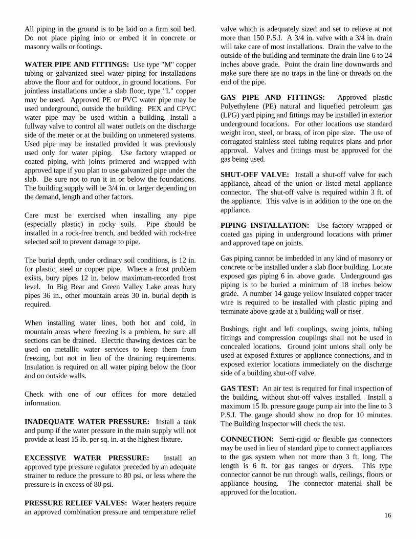
All piping in the ground is to be laid on a firm soil bed.
Do not place piping into or embed it in concrete or
masonry walls or footings.
WATER PIPE AND FITTINGS: Use type "M" copper
tubing or galvanized steel water piping for installations
above the floor and for outdoor, in ground locations. For
jointless installations under a slab floor, type "L" copper
may be used. Approved PE or PVC water pipe may be
used underground, outside the building. PEX and CPVC
water pipe may be used within a building. Install a
fullway valve to control all water outlets on the discharge
side of the meter or at the building on unmetered systems.
Used pipe may be installed provided it was previously
used only for water piping. Use factory wrapped or
coated piping, with joints primered and wrapped with
approved tape if you plan to use galvanized pipe under the
slab. Be sure not to run it in or below the foundations.
The building supply will be 3/4 in. or larger depending on
the demand, length and other factors.
Care must be exercised when installing any pipe
(especially plastic) in rocky soils. Pipe should be
installed in a rock-free trench, and bedded with rock-free
selected soil to prevent damage to pipe.
The burial depth, under ordinary soil conditions, is 12 in.
for plastic, steel or copper pipe. Where a frost problem
exists, bury pipes 12 in. below maximum-recorded frost
level. In Big Bear and Green Valley Lake areas bury
pipes 36 in., other mountain areas 30 in. burial depth is
required.
When installing water lines, both hot and cold, in
mountain areas where freezing is a problem, be sure all
sections can be drained. Electric thawing devices can be
used on metallic water services to keep them from
freezing, but not in lieu of the draining requirements.
Insulation is required on all water piping below the floor
and on outside walls.
Check with one of our offices for more detailed
information.
INADEQUATE WATER PRESSURE: Install a tank
and pump if the water pressure in the main supply will not
provide at least 15 lb. per sq. in. at the highest fixture.
EXCESSIVE WATER PRESSURE: Install an
approved type pressure regulator preceded by an adequate
strainer to reduce the pressure to 80 psi, or less where the
pressure is in excess of 80 psi.
PRESSURE RELIEF VALVES: Water heaters require
an approved combination pressure and temperature relief
valve which is adequately sized and set to relieve at not
more than 150 P.S.I. A 3/4 in. valve with a 3/4 in. drain
will take care of most installations. Drain the valve to the
outside of the building and terminate the drain line 6 to 24
inches above grade. Point the drain line downwards and
make sure there are no traps in the line or threads on the
end of the pipe.
GAS PIPE AND FITTINGS: Approved plastic
Polyethylene (PE) natural and liquefied petroleum gas
(LPG) yard piping and fittings may be installed in exterior
underground locations. For other locations use standard
weight iron, steel, or brass, of iron pipe size. The use of
corrugated stainless steel tubing requires plans and prior
approval. Valves and fittings must be approved for the
gas being used.
SHUT-OFF VALVE: Install a shut-off valve for each
appliance, ahead of the union or listed metal appliance
connector. The shut-off valve is required within 3 ft. of
the appliance. This valve is in addition to the one on the
appliance.
PIPING INSTALLATION: Use factory wrapped or
coated gas piping in underground locations with primer
and approved tape on joints.
Gas piping cannot be imbedded in any kind of masonry or
concrete or be installed under a slab floor building. Locate
exposed gas piping 6 in. above grade. Underground gas
piping is to be buried a minimum of 18 inches below
grade. A number 14 gauge yellow insulated copper tracer
wire is required to be installed with plastic piping and
terminate above grade at a building wall or riser.
Bushings, right and left couplings, swing joints, tubing
fittings and compression couplings shall not be used in
concealed locations. Ground joint unions shall only be
used at exposed fixtures or appliance connections, and in
exposed exterior locations immediately on the discharge
side of a building shut-off valve.
GAS TEST: An air test is required for final inspection of
the building, without shut-off valves installed. Install a
maximum 15 lb. pressure gauge pump air into the line to 3
P.S.I. The gauge should show no drop for 10 minutes.
The Building Inspector will check the test.
CONNECTION: Semi-rigid or flexible gas connectors
may be used in lieu of standard pipe to connect appliances
to the gas system when not more than 3 ft. long. The
length is 6 ft. for gas ranges or dryers. This type
connector cannot be run through walls, ceilings, floors or
appliance housing. The connector material shall be
approved for the location.
16

17

COUNTY OF SAN BERNARDINO
BUILDING AND SAFETY DIVISION
San Bernardino County Web Site: cms.sbcounty.gov
AREA OFFICE LOCATION OFFICE HOURS TELEPHONE
BARSTOW
Daggett
Hinkley
Newberry Springs
301 East Mt. View Avenue
Barstow, CA 92311
Monday-Friday
8:00 a.m. – 8:30 a.m.
Phone: (760) 256-4750
Fax: (760) 256-4755
BIG BEAR
Fawnskin
477 Summit Boulevard
P.O. Box 2835
Big Bear Lake, CA 92315
Tuesday
8:00 a.m. to 4:30 p.m.
Closed ½ hr. for lunch.
Phone: (909) 866-0170
Fax: (909) 866-0172
SAN BERNARDINO
Angelus Oaks
Barton Flats
Bloomington
Chino
Fontana
Forest Falls
Lytle Creek
Muscoy
Ontario
San Antonio Heights
Rancho Cucamonga
Upland
Yucaipa
San Bernardino Government Center
385 North Arrowhead Avenue
San Bernardino, CA 92415-0187
Monday - Friday
8:00 a.m. to 5:00 p.m.
Phone: (909) 387-8311
Fax: (909) 387-4301
TWIN PEAKS
Crestline
Lake Arrowhead
Running Springs
26010 State Highway 189
P.O. Box 709
Twin Peaks, CA 92391
Monday, Wednesday &
Thursday
8:00 a.m. to 4:30 p.m.
Closed ½ hr. for lunch.
Phone: (909) 336-0640
Fax: (909) 336-0616
NORTH DESERT
Apple Valley
Argus
Boron
Hesperia
Kramer
Lucerne Valley
Phelan
Trona
Victorville
Wrightwood
High Desert Government Center
15900 Smoke Tree Street
Hesperia, CA 92345
Monday - Friday
8:00 a.m. to Noon
1:00 p.m. to 5:00 p.m.
Phone: (760) 995-8140
Fax: (760) 995-8170
SOUTH DESERT
Joshua Tree
Landers
29 Palms
Yucca Valley
63655 29 Palms Hwy.
Joshua Tree, CA 92252
Wednesday
8:00 a.m. to Noon
1:00 p.m. to 4:30 p.m.
Phone: (760) 366-4160
Fax: (760) 366-4111
18 Rev. 8/17/12


