27
GUIDELINES FOR THE PUMPING OF BULK, WATER-BASED EXPLOSIVES Revised May 2010 1120 Nineteenth Street, N.W. Suite 310 Washington, DC 20036-3605 (202) 2429-9280 www.ime.org

GUIDELINES FOR THE PUMPING OF
BULK, WATER-BASED EXPLOSIVES
Revised May 2010
1120 Nineteenth Street, N.W. Suite 310
Washington, DC 20036-3605 (202) 2429-9280
www.ime.org

TABLE OF CONTENTS
CHAPTER 1 – GENERAL ........................................................................................................................................... 4
SECTION 1.1 SCOPE ................................................................................................................................................ 4 SECTION 1.2 BACKGROUND ................................................................................................................................... 4
CHAPTER 2 – TYPES AND PROPERTIES OF BULK, WATER-BASED EXPLOSIVE MATERIALS ....................................... 5
SECTION 2.1 TYPES ................................................................................................................................................. 5 SECTION 2.2 INCOMPATIBILITIES ........................................................................................................................... 5
CHAPTER 3 – PUMPING EQUIPMENT ............................................................................................................... 6
SECTION 3.1 MATERIALS OF CONSTRUCTION ........................................................................................................ 6 SECTION 3.2 PUMP BODIES .................................................................................................................................... 6 SECTION 3.3 STATORS AND ROTORS ...................................................................................................................... 6 SECTION 3.4 SEALS ................................................................................................................................................. 6 SECTION 3.5 PRODUCT HOSES ............................................................................................................................... 6 SECTION 3.6 FACTORS AFFECTING PUMP SELECTION ............................................................................................ 7 SECTION 3.7 OPERATING TEMPERATURES ............................................................................................................ 7 SECTION 3.8 OPERATING PRESSURES .................................................................................................................... 7 SECTION 3.9 PRODUCT VISCOSITY ......................................................................................................................... 7 SECTION 3.10 PUMP WEAR CONSIDERATIONS ........................................................................................................ 7 SECTION 3.11 TYPES OF PUMPS ............................................................................................................................... 7 SECTION 3.12 PROGRESSIVE CAVITY PUMPS ........................................................................................................... 8 SECTION 3.13 GEAR PUMPS ..................................................................................................................................... 8 SECTION 3.14 PISTON PUMPS .................................................................................................................................. 9 SECTION 3.15 LOBE PUMPS (ROTARY) ................................................................................................................... 10 SECTION 3.16 DIAPHRAGM PUMPS ....................................................................................................................... 10 SECTION 3.17 CENTRIFUGAL PUMPS ..................................................................................................................... 11 SECTION 3.18 PERISTALTIC PUMPS ........................................................................................................................ 11 SECTION 3.19 PUMP SYSTEM PROTECTION ........................................................................................................... 12
CHAPTER 4 – STANDARD OPERATING AND MAINTENANCE PROCEDURES .......................................................... 14
SECTION 4.1 OPERATING PROCEDURES ............................................................................................................... 14 SECTION 4.2 MAINTENANCE PROCEDURES ......................................................................................................... 16 SECTION 4.3 TROUBLESHOOTING ........................................................................................................................ 16
CHAPTER 5 – PROCESS HAZARD REVIEW ...................................................................................................... 17
SECTION 5.1 PROCESS HAZARD REVIEW ..................................................................................................................... 17
CHAPTER 6 – TRAINING ................................................................................................................................. 17
SECTION 6.1 TRAINING PROGRAMS ..................................................................................................................... 17 SECTION 6.2 DOCUMENTATION OF TRAINING..................................................................................................... 17
CHAPTER 7 – SAFETY ..................................................................................................................................... 18
SECTION 7.1 SAFETY TRAINING ............................................................................................................................ 18 SECTION 7.2 CONTACT WITH EXPLOSIVES MATERIALS ........................................................................................ 18 SECTION 7.3 PERSONNEL ..................................................................................................................................... 18 SECTION 7.4 MAINTENANCE ................................................................................................................................ 19
CHAPTER 8 – TRANSPORTATION OF EXPLOSIVE MATERIALS ON HIGHWAYS ................................................. 20
FIGURES AND CHARTS ......................................................................................................................................... 21
APPENDIX 1 ........................................................................................................................................................ 22 APPENDIX 2 ........................................................................................................................................................ 23 APPENDIX 3 ........................................................................................................................................................ 24 APPENDIX 4 ........................................................................................................................................................ 25 APPENDIX 5 ........................................................................................................................................................ 26 APPENDIX 6 ........................................................................................................................................................ 27
Copyright © 2010 Institute of Makers of Explosives. Originally published in 1998 and updated in 2010. No portion of this document may be reproduced without written
consent from the Institute of Makers of Explosives.

4
PUMPING OF BULK, WATER-BASED EXPLOSIVE PRODUCTS
CHAPTER 1 – GENERAL Section 1.1 SCOPE 1.1.1 These guidelines cover the pumping of bulk, water-based explosive and precursor products from
mobile bulk pumping equipment. The products are limited to emulsions, slurries, watergels, and blends classified by DOT as Explosive 1.5D, UN0332 or, Ammonium Nitrate Emulsion (ANE) Oxidizer, 5.1, UN3375.
1.1.2 These guidelines do not cover mixing, blending, or pumping operations at fixed explosive
materials manufacturing plants.
1.1.3 These guidelines are intended to provide safety related recommendations in the pumping of bulk, water-based explosive products from mobile bulk pumping equipment.
Section 1.2 BACKGROUND 1.2.1 The unique characteristics of water-based explosive materials has permitted them to be pumped
into boreholes or to be blended with ammonium nitrate/fuel materials for loading into boreholes. All pumping techniques used for the loading of explosives require that particular attention be paid to the products being pumped, the selection, design and development of pumping equipment, implementation of operating procedures, development of maintenance practices, and training of operating personnel.
Management should implement the following:
a. Regularly scheduled inspection programs to identify and correct potential problem areas. b. Periodic reviews of operating procedures to identify and correct unapproved changes that
may have occurred over time. c. An effective preventive maintenance program to assure adequate routine maintenance. d. A training program to assure adequate training of new employees and proper evaluation
and refresher training of experienced employees.

5
CHAPTER 2 – TYPES AND PROPERTIES OF BULK, WATER-BASED EXPLOSIVE MATERIALS Section 2.1 TYPES
a. Emulsions b. Water gels c. Slurries d. Blends e. Suspensions
2.1.1 The products covered in these guidelines are typically classified by DOT as Explosive, 1.5D or
Oxidizer, 5.1.
2.1.2 The products may be unsensitized, sensitized, or may be further sensitized by mechanical or chemical means including the use of microballoons, air injection, or chemical gassing techniques.
2.1.3 Temperatures at which the products are pumped should not exceed explosive manufacturer's
recommendations.
2.1.4 Pressures at which the products are pumped should not exceed explosive manufacturer's recommendations.
2.1.5 Typical viscosities of products to be pumped generally range from 5,000 to 100,000 centipoise
(cP) as determined by Brookfield Viscometer methods. This may vary with manufacturer. Section 2.2 INCOMPATIBILITIES 2.2.1 Emulsions, slurries water gels and blend type bulk explosive materials are generally incompatible
with strong acids, bases, copper and some elastomers.
CAUTION: Care must be exercised to insure that products are kept separated from materials with which they are incompatible.

6
CHAPTER 3 – PUMPING EQUIPMENT Section 3.1 MATERIALS OF CONSTRUCTION
NOTE: The following are typical examples only. Other materials may be used if approved by the equipment and explosive manufacturers.
AVOID THE USE OF COPPER OR COPPER Containing ALLOYS and ZINC COATED MATERIALS.
Section 3.2 PUMP BODIES Pump bodies are typically made of aluminum, stainless steel, cast iron or carbon steel. Section 3.3 STATORS AND ROTORS For progressive cavity pumps, stators are typically constructed with external walls made of aluminum, carbon steel, or stainless steel, and with internal walls of an elastomer that is compatible with the product being pumped. Rotors should have a solid shaft to prevent undetected accumulation of explosive product which could occur in a hollow shaft. In progressive cavity pumps any knuckle joint, U joint, or connector joint connectors should be protected from the product being pumped by some type of knuckle boot, or elastomer covering to prevent inclusion of product into the knuckle joint.
NOTE: To protect against wear from exposure to product, rotors may be chrome plated. Also, rotors on gear pumps are covered with an elastomer to prevent "metal-to-metal" contact. Certain elastomers degrade with time, especially when exposed to sunlight. Proper storage should be maintained.
Section 3.4 SEALS Seals are typically made of Buna-N, Teflon or Viton. Mechanical seals should be made of ceramic-to-ceramic or ceramic-to-carbon working faces.
NOTE: Lip or mechanical seals are recommended. (Avoid the use of packing glands). Section 3.5 PRODUCT HOSES All hoses should be made of materials that are compatible with the products being pumped. Discharge hoses should have the capability to withstand the temperature and pressure requirements of the pumping system. In addition, suction hoses should be constructed in such a manner to prevent collapse. Always maintain full flow to pump inlet.
7
Section 3.6 FACTORS AFFECTING PUMP SELECTION Section 3.7 OPERATING TEMPERATURES 3.7.1 Pump systems should be designed to operate at the temperature extremes encountered at blast
sites where bulk pumping operations are to be performed.
3.7.2 Product temperatures during pumping operations may cover a wide range. However, temperatures of the product as emplaced in the borehole must be compatible with the primers and detonators in use.
NOTE: For specific information on temperature compatibility consult the explosives manufacturer.
3.7.3 Heated pump jackets are not recommended for pumps that are used to pump bulk 1.5D or 5.1
materials. Section 3.8 OPERATING PRESSURES 3.8.1 Pump discharge pressures should not exceed the explosives manufacturer's recommended
pressures for the product, nor the pump manufacturer's recommended pressures for the pump.
3.8.2 Always maintain full flow to pump inlets. Section 3.9 PRODUCT VISCOSITY 3.9.1 Cold weather may raise the viscosity of bulk products to a point where they cannot be pumped
without rewarming. A danger in pumping high viscosity products is the potential to restrict flow into the pump suction cavity and entrap air, causing a no flow situation.
CAUTION: Bulk, water-based explosive products should not be pumped when the product viscosity restricts flow to the pump. Always maintain full flow to pump inlets.
Section 3.10 PUMP WEAR CONSIDERATIONS 3.10.1 Wear of pump parts over an extended period of normal operations will affect the capacity to
maintain pressure and discharge rates.
3.10.2 Small, gradual increases in pump speed will compensate for loss of pressure and capacity due to pump wear. These increases may result in slight degradation of the product being pumped. Before significant degradation of the product occurs, repair or replacement of the worn parts should be made.
3.10.3 Pump speed should be monitored and controlled by operating personnel.
3.10.3.1 On bulk pumping trucks with hydraulic systems which rely on the transmission/PTO for primary power, selection of hydraulic components during the design stage should address limiting the potential for over speed conditions.
3.10.3.2 Pumping Systems that are compressed air/hydraulic powered must be controlled by the operator to prevent excessive operating speeds.
Section 3.11 TYPES OF PUMPS Operating principles – potential problem areas – specific safety safeguard and operational recommendations.

8
Section 3.12 PROGRESSIVE CAVITY PUMPS
(See Appendix 1, Page 23, Figure 1) 3.12.1 Operating Principles
3.12.1.1 The progressive cavity pump is made up of a single helical rotor within a double threaded helical stator. As one cavity diminishes, the opposite cavity forms at the same rate to provide constant, uniform, low pulsating flow and positive displacement. The rotor is solid metal; the stator is an elastomer encased in metal housing and forms cavities with the rotor 180 degrees apart. The rotor may be connected to the drive shaft by a flexible shaft, a double U-joint, gear joints or other manufacturer's designs.
3.12.2 Potential Problems
3.12.2.1 The major concern for PC pumps is the potential for “no flow” situations while the pump is running. This condition causes the heat generated from friction of the rotor and stator to build up in the presence of potentially explosive material that can lead to detonation of said material. Depending on the speed of the pump and other conditions, critical explosive temperatures can typically be reached in 10-30 minutes. “Dead heading”, dry running, cavitation of product, air entrapment, and damage caused by unwanted material are examples of problems that could occur. Other problems that could be encountered include:
a. Friction in pump or seal, speed too high, bearing failure, confined product. b. Rotor/drive connection failure (if internal). c. Joint seal failure or flex shaft failure. d. Excessive slip because of over pressure conditions or pump wear. e. Solids build-up in suction casing that will not allow joints to rotate freely. f. Foreign materials passing through the truck storage tank and into the pump.
3.12.2.2 Avoid the use of packing glands. Lip seals or mechanical seals are recommended.
3.12.3 Specific Recommendations
3.12.3.1 Do not "deadhead" or run a pump dry. (Provide adequate protective devices.) 3.12.3.2 A preventive maintenance program is recommended for critical components
(such as bearings, internal connections, seals, flex shaft). 3.12.3.3 Lock mechanisms are recommended on internal bolts. 3.12.3.4 Flexible drive shafts may be used in place of various internal joint designs.
Section 3.13 GEAR PUMPS 3.13.1 Operating Principles (See Appendix 2, Page 24, Figure 2)
3.13.1.1 Gear pumps are made up of internal gears; one or both may be driven. Enmeshing of gears causes a vacuum to be created inducing product into the spaces between the teeth. Product is carried between the teeth and the pump housing to the discharge port. Gear pumps are classified as positive displacement type with slip depending on tolerance between casing fit to sides and diameters of the gears (for specific product and flow conditions). Pumps may have sleeves and/or side gear plates of various materials. Pump flow is pulsating, but due to speed, the number of teeth, and relatively small cavities the pulsations are usually not significant.

9
3.13.2 Potential Problems
3.13.2.1 Running the pump dry, "deadheading", cavitation of product, air entrainment, and damage caused by unwanted objects or materials are examples of problems that could occur. Other problems that could be encountered include:
a. High friction, insufficient side plate clearance. b. Product confinement in bushing area, generating heat due to high speed operation. c. Bearing failure (bearing may be located close to product on some pumps.) d. Non-compatible materials of construction. e. Bushing not lubricated. f. Delamination of rubber from steel gears; hot fresh repumpable product may cause rubber
gear coverings to wear and break apart. g. Lip seal failure on outboard bearing pumps. h. Never use a packing seal in an explosive pump.
3.13.3 Specific Recommendations
3.13.3.1 Avoid packing glands if possible. Internal components should be inspected on a routine basis. 3.13.3.2 Pumps must be lubricated in accordance with a preventive maintenance program established by the explosive manufacturer. 3.13.3.3 Pumping rate should be checked frequently against the calibrated pumping rate of new pump to determine wear. 3.13.3.4 Bare metal gears in a metal case should not be used with explosives or explosives precursors, solid rubber or elastomer covered metal gears are recommended.
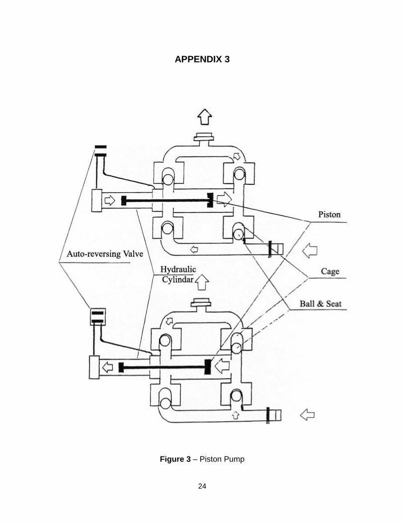
Section 3.14 PISTON PUMPS 3.14.1 Operating Principles (See Appendix 3, Page 25, Figure 3)
3.14.1.1 Piston pumps are composed of a piston in a cylinder with a back flow prevention device (typically ball check valves). A fixed volume of product is trapped inside the cylinder at suction conditions and as the piston travels forward, the product is compressed to discharge pressure and forced out the discharge nozzle of the pump. Pulsating flow is typical with single piston pumps. Flow in one direction can be controlled by internal check valves, external check valves or with an externally activated directional valve. Double-acting piston pumps will reduce the undesirable pulsation.
3.14.2 Potential Problems
3.14.2.1 "Deadheading", dry running, cavitation of product, air entrapment, and damage caused by unwanted material are examples of problems that can occur.
NOTE: Under abnormal circumstances, i.e., excessive piston seal leakage, a piston pump can be "dead-headed" by internal cycling of product from one side of the piston chamber to the other. Heat will be generated causing a potentially hazardous condition.
Other problems that can be encountered include:
a. Overheating if cycle rate is too high (resulting from friction). b. Adiabatic compression (When using piston pumps for products that contain
volatiles, care should be taken to limit pump speed in order to reduce excessive heat produced from adiabatic compression).
c. Non-compatible materials of construction. d. Over pressure
10
3.14.3 Specific Recommendations
3.14.3.1 Do not run the pump dry: Provide adequate protective devices. 3.14.3.2 Prevent introduction of unwanted material. 3.14.3.3 Clean thoroughly prior to storage.
3.14.4 Ensure metal-to-metal components are constructed in accordance with design specifications. Section 3.15 LOBE PUMPS (ROTARY) 3.15.1 Operating Principles (See Appendix 4, Page 26, Figure 4)
3.15.1.1 Rotary lobe pumps are similar in principle to gear pumps in operation. As the lobes separate, a vacuum is created drawing product into the spaces between the lobes. Product is carried between the lobes and the housing to the discharge port. Lobe Pumps are positive displacement; leakage or slip is dependent upon the internal clearance between the lobes and the casing. The pump may have sleeves and/or side wear plates. The flow is pulsating. Unlike a gear pump, the lobes are not self actuating; both lobes must be driven.
3.15.2 Potential Problems
3.15.2.1 “Deadheading”, dry running, cavitation of product, air entrapment and damage caused by unwanted material are examples of problems that could occur. Other problems that can be encountered include:
a. Product confinement in the bushing area. b. Bearing failure. c. Non-compatible materials of construction. d. Delamination of rubber covering of steel lobes. e. Over pressure of pump beyond manufacturer's recommendations.
3.15.3 Specific Recommendations
3.15.3.1 Internal components should be inspected on a routine basis. 3.15.3.2 Pumps must be lubricated in accordance with a preventive maintenance program established by the explosive manufacturer. 3.15.3.3 Pumping rate should be checked frequently against the calibrated pumping rate
of a new pump to determine wear. 3.15.3.4 Bare metal lobes in a metal case should not be used with explosives or
explosives precursors, rubber or other elastomer covered gears are recommended.
3.15.3.5 Internal components must be inspected and the drive mechanism lubricated in
accordance with a preventative maintenance schedule established by the explosive manufacture.
Section 3.16 DIAPHRAGM PUMPS 3.16.1 Operating Principles (See Appendix 5, Page 27, Figure 5)
3.16.1.1 Most diaphragm pumps have "double" diaphragms which are connected by a shaft which moves endwise. An air supply is directed through an air control valve which pressurizes one diaphragm chamber while simultaneously exhausting the opposite chamber creating a suction condition. Air pressure is applied over the entire diaphragm surface to force product to be discharged from within the pump housing. Back flow prevention is

11
typically provided by ball check valves which are manifolded to ensure flow in one direction. A four-way air distribution valve (typically externally mounted, pilot operated) directs the air pressure supply and exhaust for each chamber. Typically, diaphragm pumps will provide pulsating flow; displacement will normally equalize from each chamber. Accumulators can be used to dampen pulsations. Some pumps may contain a barrier fluid.
3.16.2 Potential Problems
3.16.2.1 Problems that may be encountered include:
a. Metal to metal contact between the outer piston or piston retainer and the casing. b. Poor "casting" quality with potential for ball check valve guide failure. c. Diaphragm failure. d. Non-compatible materials of construction. e. Air entrainment of product. f. Damage caused by unwanted materials. g. Air valves may freeze under certain operating conditions due to cooling on expansion.
3.16.3 Specific Recommendations
3.16.3.1 Inspect pump clearances prior to use and modify if necessary to prevent metal-to-metal contact.
3.16.3.2 Adjust ball check valve guide length on severely cantilevered guides (some
models).
3.16.3.3 Inspection and maintenance should be in accordance with a preventative maintenance schedule established by the explosive manufacturer.
3.16.3.4 Ensure that all materials are compatible with products being pumped.
Section 3.17 CENTRIFUGAL PUMPS
NOTE: Designs available at the time of this documents printing, are not recommended by IME member companies for pumping of explosive materials.
Section 3.18 PERISTALTIC PUMPS 3.18.1 Operating Principles (See Appendix 6, Page 28, Figure 6)
3.18.1.1 Peristaltic pumps are made up of a resilient hose inside a metal housing; the hose is squeezed by a rotor element. Pumping results from the action of alternately compressing and relaxing the hose. Product is in contact only with the inner wall of the hose. Configuration of the rotor can consist of rollers or sliding shoe mechanisms. A liquid lubricant in the housing is used to minimize friction between the rotor and hose wall. Suction capability and discharge pressure can be controlled by the amount of hose compression. "The flow is pulsating."
3.18.2 Potential Problems
3.18.2.1 Running the pump dry, "deadheading", cavitation of product, air entrapment and damage caused by unwanted material are some problems that may occur. Other problems that may be encountered include:
a. Non-compatible materials of construction. b. Loss of lubricant or incompatible lubricant. c. Tube/hose failure.
12
3.18.3 Specific Recommendations
3.18.3.1 Do not run the pump dry and do not "deadhead" the pump. (Provide adequate protective devices.) 3.18.3.2 A preventive maintenance program for critical components (i.e. shoes on rotor, rollers on rotor, flexible tube, lubricant level and condition) should be established in accordance with recommendations of the explosives manufacturer and pump manufacturer.
Section 3.19 PUMP SYSTEM PROTECTION This section 3.19 outlines general recommendations that may be considered and employed for protecting pump systems used in the delivery of bulk, water-based explosives. The properties of bulk, water-based explosives may be affected differently under certain pumping conditions. For specific explosives or materials used for manufacturing explosives, specific pumping systems, or specific requirements, consult the explosives manufacturer for its recommendations. 3.19.1 Protective Devices
Protective devices are used to prevent build up of heat in a pump system that can lead to an explosive decomposition of the product.
3.19.1.1 Pumping systems may include protective devices designed to prevent the occurrence of AN UNSAFE pumping condition. Warning devices may also be incorporated. “Dead heading”, dry running, or high pressure and temperature are examples of conditions which should be addressed in selecting protective devices. The protective devices could include any or all of the following:
a. Flow monitor/sensors/shutoff switch b. Thermocouples c. Thermofuses d. High pressure sensors and gages and/or alarms/shutoff switch e. Low pressure sensors and gages and/or alarms/shutoff switch f. Timing devices/shutoff switch g. Rupture discs (Bursting discs) h. Fusibly linked rotors
As a minimum requirement, any pumping system using progressive cavity pumps should be protected against "dead-heading", dry running or high pressure conditions. Redundancy may be desired in the pumping system protective circuits and is recommended as a good practice.
3.19.2 Discharge Side of Pump A pressure sensor may be located at pump discharge in a location where pressure in the pump can be accurately measured. The pressure readings should be accessible to the operator.
3.19.2.1 Thermocouples may be located in pump bodies to detect increases in pumping temperatures. Increases in product temperature beyond specified limits mandates immediate shutdown of pumping operations. Care must be taken to prevent metal-to-metal contact between the thermocouple and rotating pump components. Thermocouples should be installed at the location where the highest temperatures are expected.
3.19.3 Rupture Discs (Bursting Discs)
3.19.3.1 Rupture discs could potentially relieve pressure in a slow burning or single point ignition event. They can also be used to limit pumping pressure and to protect pumps against dead heading if the latter can generate at least the bursting pressure of the disc. 3.19.3.2 Standard bursting discs are made to rupture within plus or minus 10% of their designed pressure. When ordering a disc for a specific application, the operating

13
temperature must also be specified. The nominal bursting pressure should be chosen equal to the maximum safe pumping pressure minus bursting tolerance.
3.19.3.3 Personnel should be protected from the consequences of a disc bursting (deflector plate).
CAUTION: Care must be taken to install the rupture discs in accordance with the manufacturers' recommendation. Improper installation can severely affect the bursting pressure of the rupture disc. Build up and crystallization of emulsion on disks can increase the burst pressures significantly.
3.19.3.4 There is no inspection procedure to test the proper operating pressure of rupture discs. The manufacturer's rating label must be relied upon for bursting pressure information.
NOTE: Rupture disc failure rate may change over temperature and time cycles. Discs should be changed on schedule as established by the explosive manufacturer.
3.19.3.5 Piping to the rupture disc and vent piping from the rupture disc must be checked on a regular basis. Rupture disc vent pipes should be shielded or directed away from the operator's station to prevent injury from hot or pressure-vented product. Frequency of maintenance will depend upon the type of product being pumped. Pumping of blends or aluminized products will require more frequent maintenance. Inspection of protective devices should be done at the same frequency as inspection of the pump.
3.19.4 Speed and Horsepower Limiters
3.19.4.1 Hydraulic and air driven motors should be selected so that horsepower inputs are limited and speeds cannot exceed those recommended by the manufacturer. This will serve to eliminate the need for mechanical or electrical devices to control speed or limit horsepower. 3.19.4.2 Pumping conditions normally dictate the type of pump chosen for a particular application. In designing the drive system for the pump selected, manufacturer's recommendations should be followed. 3.19.4.3 To insure that speed and horsepower limits are not exceeded, equipment must be properly maintained and all defective parts must be replaced with parts that are equal to the original specified components.
3.19.5 Counters (Tachometers/Totalizers)
3.19.5.1 Counters can be used to record pump revolutions. During calibration procedures the weight of product pumped per revolution is determined. Recorded pump outputs can be compared with the output of new pumps to determine state of wear of pumps. Recorded pump output can also be used to check loading density or column buildup in boreholes.
3.19.6 Timers
3.19.6.1 Down hole delivery trucks can be fitted with a timer to automatically shut down the system once a predetermined amount of time has elapsed. This can be a very effective method to prevent heat build-up in a pump from no-flow conditions.
3.19.7 Control Systems
3.19.7.1 Down hole delivery trucks can be fitted with control systems that shut down the pump when a pre-set quantity of explosives has been delivered. This can be a very effective method to prevent running of pumps for long periods that can create excessive heat conditions.
14
CHAPTER 4 – STANDARD OPERATING AND MAINTENANCE PROCEDURES Section 4.1 OPERATING PROCEDURES 4.1.1 Pre-Operation Checks
4.1.1.1 New equipment 4.1.1.2 All pump/blend units should be checked for presence of foreign material (welding slag, gasket material, metal filings, trash, or grit) in tanks, bins and lines before being put into operation.
CAUTION: Do not use pump to flush system.
4.1.1.3 Check system with water to assure that all pipe and hose connections are tight and leak free. 4.1.1.4 Check and/or test the installed safety and operating systems such as:
a. Pump lubrication – must conform to manufacturer's specifications and must be
compatible with products being pumped. b. All guards must be in place and secure. c. Hydraulic fluid levels. d. Pressure relief system is in place and is of specified failure rating. Rupture disc vent pipe
must be clear and open if used. e. Alarms must be in working order and adjusted to proper setting. f. Pump calibration (See Section 4.1.4) g. Water ring spray system.
4.1.2 Equipment in use
4.1.2.1 Operators should be trained in proper procedures of operation, troubleshooting and maintenance and should not attempt to operate any pumping equipment until they have received adequate training. Operators should review written operating procedures before operating pumping equipment. 4.1.2.2 Check and/or visually inspect the following:
a. Hydraulic controls – must be in OFF position. b. Hydraulic fluid levels. c. Pump suction lines – possible leaks d. Pump discharge line – wear, leaks or damage. e. High pressure rupture disc. Verify that a properly rated rupture disc is in place and is
properly installed if used. f. Product tank valve – must be open to pump. g. Rupture disc vent pipe must be clear and open if used. h. Vessel vent line – ensure it is clear before pumping begins i. Discharge hose – ensure that all kinks are removed before pumping.
NEVER operate a pump against a closed valve or plugged line. Carefully evaluate any valves in the discharge lines of the pumping system.
4.1.2.3 Pumping systems equipped with a water ring designed to reduce pumping pressure by lubricating the discharge hose should be checked for proper fluid level and flow rate.

15
4.1.3 Pump operation
4.1.3.1 Always assure all fitted safety devices are operational. CAUTION: It is not recommended to operate a pump at pressures above the pump manufacturer's recommended limits. Never operate a pump at pressures above explosive manufacturer's recommended limits.
4.1.3.2 NEVER disconnect any type of alarm on a pumping system. Upon activation of an alarm, pumping operations should be shut down and not resumed until the problem has been corrected. Never override a timeout shutdown device on a pump, or continually restart the pump upon a timed-out condition.
4.1.3.3 All operators of pump or pump/blend equipment must be thoroughly trained in all phases of the operation, including starting, operating and stopping.
4.1.4 Pump calibrations
4.1.4.1 Pumps should be calibrated at the time of installation and recalibrated periodically in accordance with explosive manufacturer's recommendations.
4.1.4.2 Tolerances for pump calibration checks should be established. Pumps which do not meet calibration checks should not be used.
CAUTION: Failure of a pump to pass a calibration check could indicate excessive wear, an air leak in suction lines or a partially blocked suction or discharge hose.
4.1.4.3 Pumps that have been out of service for an extended period of time should be recalibrated before being returned to operation.
4.1.5 Loading boreholes
NOTE: Operators must be familiar with and comply with all applicable federal, state, and local regulations and recommendations.
4.1.5.1 Care must be taken when maneuvering pump or blend trucks on a blast site.
4.1.5.2 Bulk explosive materials should not be loaded into a borehole unless the hole has been properly checked and prepared and is ready for loading. 4.1.5.3 Auger booms should be returned to a cradle position prior to moving between blast sites. 4.1.5.4 Augers should be emptied of bulk explosive materials at the last borehole to be loaded before moving over public highways, or prior to idle periods.
4.1.6 Clearing loading hoses
Follow explosive manufactures and equipment manufactures recommendations. Precautions should be taken to prevent excessive pressures in the system, potential environmental spills or uncontrolled high volume air/product discharges from the hose.
4.1.7 Shutdown and Restart
4.1.7.1 Prior to an extended shutdown of a pumping unit, product tanks should be emptied, hoses cleared; and augers emptied of any product buildup.
4.1.7.2 Product removed from a pumping unit prior to or after shutdown should be inspected and disposed of properly in accordance with the explosives manufacturer’s recommendations, and local, state and federal regulations.
4.1.7.3 To restart pumping after a lengthy shutdown: Follow explosive manufactures and pump operating specifications.
16
Section 4.2 MAINTENANCE PROCEDURES 4.2.1 Accepted Practices
4.2.1.1 Only qualified pump mechanics should perform maintenance on pumps other that routine operating checks and lubrication.
4.2.1.2 A formal maintenance schedule should be established and followed.
4.2.1.3 Proper maintenance practices should be a basic part of the bulk pump operator's training program.
4.2.1.4 Maintenance records should be kept for each pumping unit and used to determine preventive maintenance cycles and service requirements.
4.2.1.5 Caution should be used to ensure overlubrication does not occur and could cause seal damage.
Section 4.3 TROUBLESHOOTING See explosive manufactures and pump procedures.

17
CHAPTER 5 – PROCESS HAZARD REVIEW Section 5.1 Process Hazard Review A process hazards review should be conducted for each pumping system design to investigate operating processes and determine possible hazards. 5.1.1 Process Hazard Review A process hazard review of pumping of bulk, water-based explosive materials should consider the following aspects of the operation:
a. Nature of the product being pumped. b. Conditions at the pump inlet and outlet. c. The pump and the power source. d. Pump controls, including speed, pressure, temperature and flow. e. The environment around the pump. f. The operator and operating procedures.
5.1.2 A process hazard evaluation should be re-evaluated on a predetermined interval. 5.1.3 Whenever a new or modified pumping system design is introduced (including changes in product, equipment design, process materials, or procedures), the pumping system design operation should be included in a Management of Change program and additional process hazard evaluation completed.
CHAPTER 6 – TRAINING Section 6.1 TRAINING PROGRAMS
A training program should be instituted and specific for each type of pump. Refer to IME Safety Library Publication No. 25, Explosives Manufacturing & Processing Guideline to Safety Training, for reference 6.1.
Section 6.2 DOCUMENTATION OF TRAINING 6.2.1 All training should be documented.

18
CHAPTER 7 – SAFETY Section 7.1 SAFETY TRAINING A formal safety training and retraining program addressing personal safety, explosive materials handling, operating procedures and equipment should be instituted and maintained. 7.1.1 Personnel working around bulk loading equipment should wear safety glasses or safety goggles
and safety shoes at all times. Proper safety equipment must be in accordance with practices mandated by MSHA, OSHA, and state and local agencies. Hard hats should always be worn when working around equipment where items could fall or a head bump hazard exists.
7.1.2 Loose clothing, necklaces, chains, or bracelets should not be worn when operating or working
around bulk loading equipment. Exception: when driving the bulk truck and no loading, mixing, or pumping is involved.
7.1.2.1 Gloves should be worn when hand contact with materials used in product formulation cannot be avoided. 7.1.2.2 Safety glasses (with eye shields) or goggles should be worn at all times. 7.1.2.3 Open cuts should be protected to prevent contact with explosives materials or ingredients.
Section 7.2 CONTACT WITH EXPLOSIVES MATERIALS Contact with explosives materials or ingredients, especially prolonged contact, may cause a stinging sensation, burning, or dermatitis. Consult MSDS's for product involved. 7.2.1 Contact with eyes may cause a burning sensation – flush eyes with water for at least 15 minutes
– Consult a doctor immediately. 7.2.2 If a rash or other signs of dermatitis appear consult a doctor immediately. 7.2.3 Ingestion of explosives materials or ingredients may cause nausea or other symptoms of illness.
Consult a doctor immediately. 7.2.4 Contaminated clothing could be a fire hazard or could cause dermatitis through prolonged
contact. Contaminated clothing should be removed and cleaned before reusing. 7.2.5 Spills should be cleaned up immediately, especially on ladders and walking areas as products are
often slippery. Spills should be disposed of in accordance with applicable regulations. 7.2.6 When large spills of explosives materials occur the manufacturer should be contacted for advice
and recommendations. Section 7.3 PERSONNEL Personnel operating bulk loading equipment should understand and practice standard operating safety procedures before the equipment is put into operation. 7.3.1 Protective guards MUST be in place over rotating joints. 7.3.2 Clean-out doors MUST be closed and latched before starting augers. 7.3.3 Power take off must be DISENGAGED before any attempt is made to clean out jammed augers
or make any repairs to augers involving potential operator contract. 7.3.4 "LOCKOUT AND TAG OUT" procedures MUST be followed when performing maintenance. 7.3.5 Check for snags or burrs on ends of auger flights. Repair before starting operations.
19
7.3.6 Clear personnel away from augers before starting operation. 7.3.7 Make visual check of hydraulic motor mounts and pump mounts. Secure if necessary. 7.3.8 Visually check condition of hoses. Replace worn or damaged hoses immediately. Avoid pinch
points around hose reel. 7.3.9 Visually check high pressure rupture disc. Make sure that proper disc is in place and that rupture
disc vent pipe is clear and open if so equipped. 7.3.10 NEVER RUN A PUMP “DEAD-HEADED” or dry unless under controlled test procedures. 7.3.11 Smoking, matches, flame producing devices, open flames, or firearms and ammunition are
prohibited within 50 feet of the equipment or the blast site. Section 7.4 MAINTENANCE Operators should follow prescribed safety procedures when performing routine maintenance or making repairs to bulk trucks. 7.4.1 Prior to routine maintenance or minor repairs, the exterior of the bulk truck should be cleaned. 7.4.2 Before making major repairs, all product piping and product transfer pumps should be
thoroughly cleaned. Transfer augers should be washed out. 7.4.3 No welding or open flames are to be used on or around any part of a bulk truck or other bulk
pumping equipment until all oxidizing materials, fuels, and explosive materials have been removed and the equipment has been thoroughly cleaned by washing down or steam cleaning.
7.4.4 Before welding or making repairs to hollow auger shafts, all fuels and oxidizing materials shall be
removed from the outside and inside of the shaft by a thorough washing or steam cleaning and the shaft has been vented with a minimum of ½ -inch diameter opening at each end. For hollow shafts with an outside diameter of less than ½ -inch, the diameter of the vent holes should be not less than one-third the outside diameter of the shaft.

20
CHAPTER 8 – TRANSPORTATION OF EXPLOSIVE MATERIALS ON HIGHWAYS
NOTE: All transportation must comply with applicable federal, state or local regulations.

21
FIGURES AND CHARTS Page Number
Figure 1 Progressive Cavity Pump (Appendix 1) 23
Figure 2 Gear Pump (Appendix 2) 24
Figure 3 Piston Pump (Appendix 3) 25
Figure 4 Lobe Pump (Rotary) (Appendix 4) 26
Figure 5 Diaphragm Pump (Appendix 5) 27
Figure 6 Peristaltic Pumps (Appendix 6) 28

22
APPENDIX 1
Figure 1– Cross-sectional view: progressing cavity pump of a modern modular type.

23
APPENDIX 2
Figure 2 – Gear Pump
24
APPENDIX 3
Figure 3 – Piston Pump

25
APPENDIX 4
Figure 4 – Lobe Pump (Rotary)

26
APPENDIX 5
Figure 5 – Diaphragm Pump

27
APPENDIX 6
Figure 6 – Peristaltic Pump


