36
Guidelines for the Safe Operation and Maintenance of Marinas by the National Water Safety Congress 2001 Revision of 1988 Guidelines

Guidelines for the Safe Operation and Maintenance of Marinas by the
National Water Safety Congress
2001 Revision of 1988 Guidelines
Guidelines for the Safe Operation and Maintenance of Marinas by theNational Water Safety Congress
2001 Revision of 1988 GuidelinesNational Water Safety Congress Incorporated
2000-2002 Officers
PRESIDENTStephen B. Fairbanks
5600 NW 78th Ave.Johnson, IA
50131
EXECUTIVE VICE PRESIDENTRonald Riberich
400 West Summit Hill Dr.Knoxville, TN
37923
TREASURERToni M. Rushing
1433 Laurel Lake Rd.London, KY40744-9739
EXECUTIVE SECRETARYArlyn Hendricks
Rt. 1, Box 260Copan, OK
74022
i
Guidelines for the Safe Operation and Maintenance of Marinas
2001 Acknowledgments
NWSC Board Members Brenda A. Warren and Emmett E. Forte prepared this update to the original guidelinespublished in 1988. Lu P. Christie, NWSC Board Member, Kristina M. Meredith, National Park Service, JosephMorgan, Federal Energy Regulatory Commission, Betsy Woods, Tennessee Wildlife Resources Agency, LindaHarris, Tennessee Valley Authority, and Dr. Thomas W. Olson, US Army Corps of Engineers provided assistance.The contributions of time, effort, and information to review the revision by the following are acknowledged with deepappreciation:
Alabama Power CompanyChelan Public Utility DistrictEntergy Incorporated Pacific Gas and Electric CompanyRecreation Safety InstituteTennessee Valley AuthorityU.S. Army Corps of EngineersU.S. Coast Guard
1986-1988 OFFICERS
PRESIDENTAllan G. Bailey
PO. Box 1159Cincinnati, OH
45201
EXECUTIVE VICE PRESIDENTBrad J. Keshlear
510 Title Bldg., 30 Pryor St. SWAtlanta, GA30335-6801
TREASURERRay Miller
5380 Franklin RoadBoise, ID
83705
EXECUTIVE SECRETARYCarl A. Bishop
P. O. Box 1137Warrenton, VA
22186
ii
Guidelines for the Safe Operation and Maintenance of Marinas

1988 Acknowledgments
These recommendations were developed with the support and assistance of several organizations interested inwater safety and in safe marinas. The contributions of time, effort, and information by the following are acknowledged with deep appreciation:
American Red CrossGeorgia Power CompanyNational Park ServiceOhio Department of Natural ResourcesOutdoor Empire Publishing, Inc.Rolyan Mfg. CompanyTennessee Valley AuthorityU.S. Army Corps of EngineersU.S. Coast GuardU.S. Forest Service
iii
Guidelines for the Safe Operation and Maintenance of Marinas
Foreword
The National Water Safety Congress (NWSC) was formed in 1951 to promote the safe use of the nation's watersfor recreational purposes. Its membership consists of a broad base of individuals and organizations interested inwater safety, including many of the top water safety professionals in the United States.
The NWSC encourages participants in water activities-i.e., boaters, swimmers, divers, skiers, anglers, commercialboat operators, etc.-to obtain safety instruction in their field of endeavor. The NWSC promotes water safety throughthe press, radio, television, and films and through promotion of the work of other organizations such as theAmerican Red Cross, U.S. Coast Guard and U.S. Coast Guard Auxiliary, U.S. Power Squadron, U.S. Army Corps ofEngineers, National Park Service, U.S. Forest Service, Tennessee Valley Authority, and others.
The NWSC develops, publishes, and distributes boating safety education courses and materials; collects, compiles,and distributes water accident statistics; encourages state governments to establish water safety programs;promotes uniform legislation and encourages reciprocity of laws among states; and publicly recognizes individuals,organizations, and business firms for their efforts in promoting boating and general water safety. The NWSCannually co-sponsors with the National Safe Boating Council the International Boating and Water Safety Summit,which provides professional boating and water safety training for federal, state, and local boating and water safetyeducation and management personnel.
Introduction
These recommendations provide a guide for minimum safety requirements for the operation and maintenance ofmarinas to ensure adequate protection of the public from mishaps. Compliance is required with the followingfederal, state, and local codes: the National Fire Protection Association Codes, particularly but not limited to #7(National Electric Code); #30 (Flammable and Combustible Liquids Code), 30A (Code for Motor Fuel DispensingFacilities and Repair Garages), #302 (Fire Protection Standard for Pleasure and Commercial Motor Craft), #303(Fire Protection Standard of Marinas and Boatyards), #307 (Standard for the Construction and Fire Protection ofMarine Terminals, Piers, and Wharves), #312 (Standard for the Fire Protection of Vessels During Construction,Repair, and Lay-up), #325 (Guide to Fire Hazard Properties of Flammable Liquids, Gases, and Volatile Solids),#326 (Standard for the Safeguarding of Tanks and Containers for Entry, Cleaning, and Repair), #329(Recommended Practices for Handling Releases of Flammable and Combustible Liquids and Gases), and #820(Standard for Fire Protection in Wastewater Treatment and Collection Facilities); and Code of Federal Regulations,Title 40, Subchapters D (Water Programs), H (Ocean Dumping), I (Solid Wastes), J (Superfund, EmergencyPlanning, and Community Right-To-Know Programs), N (Effluent Guidelines and Standards), O (Sewer Sludge),and R (Toxic Substances Control Act).
The involvement of professional planners and designers in marina facilities is of vital importance to public safety. Itis equally important to public safety that capable and qualified personnel are involved in the management of marinaoperations and maintenance.
iv
Guidelines for the Safe Operation and Maintenance of Marinas
Table of Contents
1. Boat Launching Ramps . . . . . . . . . . . . . . . . . . . . . . . . . . . . . . . . . . . . . . . . . . . . . . . . . . . . . . . . .1
2. Dock Flotation . . . . . . . . . . . . . . . . . . . . . . . . . . . . . . . . . . . . . . . . . . . . . . . . . . . . . . . . . . . . . . . .2
3. Anchorage . . . . . . . . . . . . . . . . . . . . . . . . . . . . . . . . . . . . . . . . . . . . . . . . . . . . . . . . . . . . . . . . . . .2
4. Fuel Dispensing Areas . . . . . . . . . . . . . . . . . . . . . . . . . . . . . . . . . . . . . . . . . . . . . . . . . . . . . . . . . .3
5. Fire Protection . . . . . . . . . . . . . . . . . . . . . . . . . . . . . . . . . . . . . . . . . . . . . . . . . . . . . . . . . . . . . . . .5
6. Bulk Fuel Tank Storage . . . . . . . . . . . . . . . . . . . . . . . . . . . . . . . . . . . . . . . . . . . . . . . . . . . . . . . . .6
7. Storage of Flammable Liquids . . . . . . . . . . . . . . . . . . . . . . . . . . . . . . . . . . . . . . . . . . . . . . . . . . .8
8. Battery Storage and Charging Areas . . . . . . . . . . . . . . . . . . . . . . . . . . . . . . . . . . . . . . . . . . . . . . .9
9. Electrical Systems . . . . . . . . . . . . . . . . . . . . . . . . . . . . . . . . . . . . . . . . . . . . . . . . . . . . . . . . . . . .10
10. Grounding . . . . . . . . . . . . . . . . . . . . . . . . . . . . . . . . . . . . . . . . . . . . . . . . . . . . . . . . . . . . . . . . . .14
11. Walkways . . . . . . . . . . . . . . . . . . . . . . . . . . . . . . . . . . . . . . . . . . . . . . . . . . . . . . . . . . . . . . . . . .15
12. Handrails . . . . . . . . . . . . . . . . . . . . . . . . . . . . . . . . . . . . . . . . . . . . . . . . . . . . . . . . . . . . . . . . . . .15
13. Throwable Lifesaving Devices and First Aid . . . . . . . . . . . . . . . . . . . . . . . . . . . . . . . . . . . . . . . . .16
14. Housekeeping . . . . . . . . . . . . . . . . . . . . . . . . . . . . . . . . . . . . . . . . . . . . . . . . . . . . . . . . . . . . . . .16
15. Sewage Management . . . . . . . . . . . . . . . . . . . . . . . . . . . . . . . . . . . . . . . . . . . . . . . . . . . . . . . . .17
Appendix A: Minimum Design Criteria for Fixed and Floating Structures . . . . . . . . . . . . . . . . . . . . . . .19
Appendix B: Recommended Safeguards for Installation of Underground Tanks . . . . . . . . . . . . . . . . . .23
Appendix C: Sample Marina Inspection Checklists . . . . . . . . . . . . . . . . . . . . . . . . . . . . . . . . . . . . . . .25
v
Guidelines for the Safe Operation and Maintenance of Marinas

vi
Guidelines for the Safe Operation and Maintenance of Marinas
1. Boat Launching Ramps
1.1 Launching ramps should be designed to require a deliberate turn from the access road onto the ramp. Trafficcontrol devices, such as barricades, traffic islands, berms, or other architectural barriers, may be used toensure access roads are not in direct alignment with the ramp. This will prevent direct access to the rampand keep unaware persons from driving directly into the water. Where turns or control devices are notfeasible, rumble strips, signs, and street lights should be installed.
1.2 Ramps should be from 12 to 14 feet wide per anticipated lane and should extend at least 4 feet below thelow water level.
1.3 Slope should be between 12 and 16 percent above the water line and 15 to 20 percent below the water line.
1.4 Each ramp should include a minimum of one, 75-foot-diameter vehicular turnaround.
1.5 Ramps should have retaining curbs at the lower end of the ramp and on the outside edges of ramps wheredrop-offs exist or could form.
1.6 Ramp surfaces should be scored or patterned to provide adequate traction.
1.7 Where feasible, chock blocks should be provided at each launching ramp and a sign placed to encouragetheir use.
1.8 Ramps should be kept free of algae growth and silt build-up, which could create slipping hazards.
1.9 A sign should be located at the launching area and should include appropriate statements, such as:
l No swimming or wading.l Get all passengers out of vehicle.l Leave door open on driver's side. Unfasten boat hold-down strap.l Is your drain plug in?l Do you have the necessary safety equipment in your boat?l Alcohol and boating don't mix.l Boat safety - make sure someone knows where you are boating and when you will
return or file a float plan.l The phone number for emergency services is ------_________________.l No wake or appropriate boat operating instructions.
1.10 Boat launching, rigging, and parking areas and access roads to boat ramps should be free of overheadpower lines. Where overhead power lines are present at launching, rigging, and parking areas, warningsigns should be posted.
1.11 Launching ramps should have a security light for safety.
1.12 Courtesy loading docks should be provided at boat ramps. This will allow for safe loading and unloading ofpersons and gear.
1
Guidelines for the Safe Operation and Maintenance of Marinas

2. Dock Flotation
2.1 Flotation should be of materials fabricated for marine use. The flotation material should be expanded,encased, or encapsulated and 100 percent warranted for a minimum of 8 years against sinking, becomingwaterlogged, cracking, peeling, fragmenting, or losing beads. All flotation material should resist puncture andpenetration and should not be subject to damage by animals under normal conditions for the area. Allflotation material should be fire resistant. The use of new or recycled plastic or metal drums or non-compart-mentalized air containers for encasement should be prohibited.
2.2 Repair or replacement should be required when flotation material no longer performs its designated functionor it fails to meet the specifications for which it was originally warranted.
2.3 Flotation should be adequate to maintain a stabilized and safe structure capable of supporting use loads. Atleast 40 percent of the flotation should be above the waterline under all conditions.
2.4 Flotation should be securely fastened to the dock using galvanized steel straps, treated wood dowels,galvanized bolts, or other acceptable methods.
2.5 Type GR-gasoline resistant flotation - should be required on all new gas docks and within 40 feet of a linecarrying fuel or when replacing flotation under existing gas docks.
3. Anchorage
3.1 An anchorage system should be provided for mooring all floating structures, taking into consideration waterdepth, fluctuation, and exposure to wave and wind action. Anchorage systems, such as dead man or groundstakes, should be installed flush with existing grade. Anchor cables or other securing devices should not beattached to trees, stumps, power poles, or guardrail posts. Anchor cables should be fastened with aminimum of three U-bolts or fist grip clamps. All anchor lines should be installed in a manner that will notcreate a tripping hazard. Anchorage systems should be so situated, marked, and/or guarded so they do notconstitute a navigation or other hazard. Floating facilities should be securely anchored to prevent them fromfloating free during major floods.
3.2 Winches located on docks should have cable guards and be mounted so they do not create a hazard.
2
Guidelines for the Safe Operation and Maintenance of Marinas

4. Fuel Dispensing Areas
4.1 The fuel dispensing area should be located a sufficient distance from other structures to allow adequateroom for safe ingress and egress of craft to be fueled. Dispensing units should be at least 25 feet from anyactivity not associated with the handling of fuel.
4.2 Approved dispensing units, with or without integral pumps, should always be used. Units may be located onopen piers, wharves, floating docks, on shore, or on piers of the solid fill type.
4.3 Tanks and pumps not integral with the dispensing unit should be on shore or on a pier of the solid fill typeand located above the maximum water level elevation.
4.4 In a situation where shore location would require excessively long supply lines to dispensers, the authorityhaving jurisdiction may grant permission for installation of tanks on a pier. Applicable portions of the BulkFuel Tank Storage section of this manual (Section 6) relative to spacing, diking, and piping should beadhered to, and the quantity so stored should not exceed 1,100 gallons aggregate capacity.
4.5 Shore tanks supplying marine service stations may be located above ground where rock ledges, limitedspace, or a high water table make underground tanks impractical. Applicable portions of Section 6, Bulk FuelTank Storage, of this manual relative to spacing, diking, and piping should be adhered to. All federal, state,and local regulations concerning aboveground storage tanks must be followed, including the spill preventioncontrol and countermeasure (SPCC) regulations found in 40 CFR, Part 112.
4.6 In a situation where tanks are at an elevation that would produce gravity head on the dispensing unit, thetank outlet should be equipped with a pressure control valve positioned adjacent to and outside the tankblock valve, and it should be adjusted so liquid cannot flow by gravity from the tank in case of piping or hosefailure.
4.7 Piping between shore tanks and dispensing units should be as specified in Section 6, Bulk Fuel TankStorage, except that, where dispensing is from a floating structure, suitable lengths of oil-resistant flexiblehose may be employed between the shore piping and the piping on the floating structure as madenecessary by change in water level or shoreline.
4.8 A readily accessible and posted valve to shut off the fuel supply from shore should be provided in eachpipeline at or near the approach to the pier and at the shore end of each pipeline adjacent to the point whereflexible hose is attached.
4.9 Piping should be located so it is protected from physical damage. Corrosion protection for piping is alsorequired (details are provided in Section 6 of this manual).
4.10 Pipes that handle Class I liquids should be grounded to control stray currents.
4.11 STORAGE AND HANDLING OF FUELS: The fueling station should be located to minimize the exposure ofall other plant facilities. Where tide and weather exposure conditions permit, all fuel handling should beoutside the main berthing area.
3
Guidelines for the Safe Operation and Maintenance of Marinas

4.12 Inside fueling stations should be located near an exit by water from the berthing area or at some otherlocation from which, in case of fire aboard a boat alongside, the stricken craft may be quickly removedwithout endangering other boats or structures nearby.
4.13 When practical, fueling station docks, including the fuel system piping, should be detachable by means ofquick disconnect systems that allow complete removal of the dock by pushing or towing it to a safe locationshould it catch fire, and piping disconnects that should prevent spillage of any fuel.
4.14 Dispensing units for transferring fuels from storage tanks should be in accordance with provisions of theFlammable and Combustible Liquids Code (NFPA No. 30). Every fuel delivery nozzle should be equippedwith a self-closing control valve, which will shut off the flow of fuel when the operator's hand is removed fromthe nozzle. THE USE OF ANY AUTOMATIC NOZZLE WITH A LATCH-OPEN DEVICE SHOULD BEPROHIBITED. In the construction of the fuel hose assembly, provisions should be made so the fuel deliverynozzle is properly bonded to the shore electric grounding facilities.
4.15 All boat fueling operations should be carefully accomplished in accordance with NFPA 302, "Fire ProtectionStandard for Pleasure and Commercial Motor Craft."
4.16 Fueling from cans should be discouraged.
4.17 For the purpose of this section, fuel pipes shall mean all pipelines, tubing, or hoses that are conductors offuel from the deck filling plate to the engine connection. Related accessories should include any attachmentsto fuel pipes, such as valves, strainers, pumps, connecting fittings, etc.
4.18 Fuel pipes should be accessible. Fuel pipe connections and accessories should be readily accessible.
4.19 Fuel pipes should be adequately secured against excessive movement or vibration, protected from potentialdamage, and should have several piping disconnects with automatic shut-off valves in case the piping getsbroken or separated.
4.20 Outlets for drawing gasoline below deck for any purpose should be prohibited.
4.21 When making up threaded pipe connections, an approved sealing compound, resistant to gasoline, shouldbe used.
4.22 When making flared tube connections, it is essential that tubing be cut squarely and be truly flared by toolsdesigned for those purposes.
4.23 SIGNS. It is recommended that locations such as fueling stations, areas used for the storage and handlingof fuel or other flammable liquids, boat storage sheds, paint and woodworking shops, sail lofts, batterycharging rooms, boat locker rooms, and storage rooms, display the sign:
"SMOKING AND OPEN FLAMES PROHIBITED."
4.24 A means of notifying appropriate authorities must be available should a fire break out or another emergency occurs.
4.25 A means of extinguishing small fires quickly must be readily available. See Section 5.
4
Guidelines for the Safe Operation and Maintenance of Marinas

5. Fire Protection
5.1 Portable fire extinguishers of approved type 2A:20-B:C and suitable to the hazards and circumstancesshould be provided throughout the property and located so an extinguisher is within 50 feet of any point. Aminimum of two, 4-A:40-B:C should be located outside of and within 30 feet of each fuel pump and in clearview in the gas dock area. These fire extinguishers should be placed at least 15 feet apart, if possible. Fireextinguishers should be inspected monthly.
5.2 The gasoline dispensing and other areas where flammable materials are stored or used should be posted asidentified in Section 4.23.
5.3 A clearly identified and readily accessible emergency shutoff switch that can be used to shut off the supplyof power to gasoline pumps should be located on land and near the dispensing pumps should a leakdevelop.
5.4 Hoses and nozzles should be in accordance with Section 4.14.
5.5 At least one Coast Guard approved throw-type flotation device (with at least 60 feet of ¾-inch diameter rope attached or a reach pole) should be located in clear view on the gas dock and every 200 feet on other docks.
5.6 Immediate notification to the nearest fire department in the event of fire should be the established operatingprocedure. An approved means for sounding an alarm to notify yard personnel and others of a fire on thepremises should be provided.
5.7 All fire extinguisher locations should be clearly marked and within easy access. Fire extinguishers should beinspected monthly to ensure they operate properly, when needed.
5.8 Emergency phone numbers should be posted conspicuously near the telephone.
5.9 Combustible waste material and residues should be kept to a minimum, stored in covered metal receptacles,and disposed of daily.
5.10 National Fire Protection Codes should be consulted for specific details. (See Introduction to this manual forlist of codes.)
5.11 Local fire department personnel should be invited to inspect the facility with special emphasis on access todifferent areas of the marina in order to fight a fire.
5.12 A safety skiff should be available and ready for use. The skiff should be equipped with a wire rope and anattached grabble hook. This skiff should be used to tow a vessel that may be on fire to open water and awayfrom other craft or structures.
5
Guidelines for the Safe Operation and Maintenance of Marinas
6. Bulk Fuel Tank Storage
(See Appendix B for additional information)
6.1 TANK PLACEMENT. The excavation for an underground tank should provide a firm level base. Ledges or highspots, which might stress the tank, should be avoided. Particular care must be taken when an underground oraboveground tank is to be placed on fill or rocky ground. Fuel storage tanks should be installed in accordancewith the Flammable and Combustible Liquids Code and all federal, state, and local ordinances. Dropping the tankor rolling it into the hole should not be permitted. Such handling may break a weld, puncture or damage the tankmetal, and may scrape off the protective coating if the tank has been coated.
6.2 LOCATION. Excavations for underground storage tanks should be made with care to avoid underminingfoundations of existing structures. Underground tanks or tanks under buildings should be located withrespect to existing building foundations and supports so that loads carried by the latter cannot be transmittedto the tank. Aboveground tanks should be located such that they are protected against unauthorized accessand vehicular collisions. Bulk storage of fuel on floating docks is not recommended. Tanks should be locatedon land above maximum water level elevation.
6.3 DEPTH AND COVER. Underground tanks should be set on firm foundations and surrounded with at least 6inches of non-corrosive, inert materials, such as clean sand, earth, or gravel, well tamped in place. Tanksshould be covered with a minimum of 2 feet of earth, or be covered with not less than 1 foot of earth, on topof which should be placed a slab of reinforced concrete not less than 4 inches thick. When undergroundtanks are, or are likely to be, subject to traffic, they should be protected against damage from vehiclespassing over them by at least 3 feet of earth cover or 18 inches of well tamped earth, plus 6 inches ofreinforced concrete or 8 inches of asphaltic concrete. When asphaltic or reinforced concrete paving is usedas part of the protection, it should extend at least 1 foot horizontally beyond the outline of the tank in alldirections.
6.4 CORROSION PROTECTION. One or more of the following methods should provide corrosion protection forthe tank and its piping:
a. Use of protective coatings or wrappings,
b. Cathodic protection, or
c. Corrosion-resistant materials.
NOTE: Selection of the type of protection to be employed should be based upon the corrosion history of the area.
6.5 LOCATION AND ARRANGEMENT OF VENTS. Vent pipes from tanks should be located so the dischargepoint is outside of buildings, higher than the fill pipe opening, and not less than 12 feet above the adjacentground level. Vent pipes should discharge only upward to disperse vapors. Vent pipes, 2 inches or less ininside diameter, shall not be obstructed by devices that will cause excessive back pressure. Vent pipeoutlets should be located so flammable vapors will not enter building openings or be trapped under eaves orother obstructions. If the vent pipe is less than 10 feet long or greater than 2 inches in inside diameter, theoutlet should be provided with a vacuum and pressure relief device, or there should be an approved flamearrestor in the vent line at the outlet or within the approved distance from the outlet. In no case should aflame arrestor be located more than 15 feet from the outlet end of the vent line.
6
Guidelines for the Safe Operation and Maintenance of Marinas
6.6 STORAGE TANK ANCHORAGE. Each tank should be safeguarded against movement when empty andsubmerged by high ground water or floodwaters by anchoring, weighting with concrete or other approvedsolid loading material, or securing by other means. Each such tank should be constructed and installed so itwill safely resist external pressures due to high ground water or floodwaters.
6.7 DRAINAGE AND DIKED AREAS. The area surrounding an aboveground tank or a group of abovegroundtanks should be diked to provide secondary containment in prevention of discharging liquid from the tank(s),endangering adjoining property, or reaching waterways. The volume of the diked area shall comply with thefollowing requirements:
a. The volumetric capacity of the diked area or secondary containment basin should not be less than 110percent of the largest tank within the diked area, assuming a full tank. The capacity of the diked areaenclosing more than one tank should have a capacity at least equal in volume to that of the largest tankplus 10 percent of all other tanks enclosed.
b. Walls of the diked area or secondary containment basin should be of earth, steel, concrete, solidmasonry, or an approved material for tanks that is compatible with fuels, designed to be liquid tight andto withstand a full hydrostatic head. Earthen walls should be compacted and 3 feet or more in height,having a flat section at the top of not less than 2 feet wide. The slope of earthen walls should beconsistent with the angle of repose of the material of which the walls are constructed.
c. The walls of the diked area should be restricted to an average height of 6 feet above the interior grade.
d. Secondary containment can be constructed as a "tank in a tank" or a "tank in a box."
e. When provision is made for draining water from diked areas, drainage should be provided at a uniformslope of not less than 1 percent away from tanks toward a sump, drainbox, or other safe means ofdisposal located at the greatest practical distance from the tank. Such drains should normally becontrolled in a manner so as to prevent flammable or combustible liquids from entering natural water-courses, sewers, or drains if their presence would constitute a hazard. Drainage controls should beaccessible under fire conditions. No loose combustible material, either empty or full drum or barrel,should be permitted within the diked area.
6.8 FUEL PIPELINES. Fuel pipelines should be installed in accordance with the provisions of the Flammableand Combustible Liquids Code (NFPA No. 30) and any other applicable federal, state, or local regulation orcode.
a. Piping materials should be steel, of non-corrosive materials if used underground, or as specified by theproperties of the flammable or combustible liquid handled. Piping built of materials other than steelshould be designed to specifications embodying principles recognized as good engineering design forthe material used.
b. Piping should be installed free of leaks and in a manner to prevent leaks from developing. Welded,screwed joints, or approved connectors should be used. Flanged joints are not recommended forunderground service, but, if used, they should be of steel. Threaded joints and connections should betight with a suitable lubricant or piping compound. Hard setting compounds, such as litharge or red lead,are prohibited.
7
Guidelines for the Safe Operation and Maintenance of Marinas

c. Pipes passing through concrete or under paved areas (roads, sidewalks, parking lots, etc.) should be inpipe sleeves, mastic, or be otherwise free to allow for settlement, frost action, vibration, or traffic.
d. Where dispensing is from a floating structure, suitable lengths of oil-resistant flexible hose may beemployed between the shore piping and the piping on the floating structure as necessary by change inwater level.
e. It is recommended that secondary containment of piping be used. Examples include piping sleeves,double-walled piping, impermeable trenches, and piping chase.
6.9 VALVES.
a. Readily accessible valves to shut off the fuel supply from shore should be provided on each pipelineadjacent to the point where flexible hose is attached.
b. Where tanks are at an elevation that would produce gravity head on the dispensing unit, the tank outletshould be equipped with a pressure solenoid control valve positioned adjacent to and outside the tankblock valve, adjusted so liquid cannot flow by gravity from the tank in case of piping or hose failure.
7. Storage of Flammable Liquids
7.1 Rooms where flammable liquids are stored should be ventilated so there is no accumulation of flammablevapors. As a minimum, natural ventilation should be provided by air intake and exhaust vents located onopposite walls approximately 12 inches off the floor.
7.2 Smoking should be prohibited, and "No Smoking" signs should be posted in the storage rooms and on theoutside walls of the room.
7.3 Batteries should not be stored in the same room with flammable liquids.
7.4 Storage of all flammable liquids in portable containers should be ONLY in approved type safety containerswith flame arrestors and labeled for contents.
7.5 Fire extinguishers should be located in conspicuous and easily accessible locations.
7.6 Metal containers and portable tanks (less than 2.5 cubic meters/660 gallons individual capacity) meeting therequirements of and containing products authorized by Chapter 1, Title 49 of the Code of FederalRegulations (US DOT Hazardous Materials Regulations), Chapter 9 of the United Nations Rules for theTransportation of Dangerous Goods, or NFPA 386, Standard for Portable Shipping Tanks for Flammable andCombustible Liquids, should be used for transportation or storage of flammable or combustible liquids.
7.7 Portable tanks (less than 2.5 cubic meters/660 gallons individual capacity) should be provided with one ormore devices installed in the top with sufficient emergency venting capacity to limit internal pressure underfire exposure conditions to 69 kPa (10 psig) or 30 percent of the bursting pressure of the portable tank,whichever is greater.
8
Guidelines for the Safe Operation and Maintenance of Marinas
a. At least one pressure-activated vent having a minimum capacity of 170 cubic meters (6,000 cubic feet) offree air per hour should be used; it should be set to open at not more than 35 kPa (5 psig).
b. If fusible vents are used, they should be actuated by elements that operate at a temperature notexceeding 115 degrees Centigrade (300 degrees Fahrenheit).
c. Where plugging of a pressure activated vent can occur, fusible plugs or venting devices that soften to failure at a maximum of 115 degrees Centigrade (300 degrees Fahrenheit) under fire exposure shouldbe permitted to be used for the entire emergency venting requirement.
8. Battery Storage and Charging Areas
8.1 Rooms where batteries are charged should be well ventilated near the ceiling to disperse accumulation ofgases.
8.2 Flammable liquids should not be stored in battery storage and charging rooms.
8.3 All metal parts in the battery room should be of corrosion-resistant material or suitably protected from corrosion.
8.4 Smoking should be prohibited and "No Smoking" signs should be posted in the charging and storage roomand on the outside of the room.
8.5 A fully charged 2-A:40-B:C fire extinguisher should be located on the outside wall of all battery storage andcharging rooms.
8.6 Facilities in compliance with 29 CFR, Part 1910.151, "Emergency Services and First Aid," for quick drenching of the eyes and body should be provided for emergency use in the work area.Examples include an eye wash and safety shower.
8.7 When charging batteries, battery vent caps should be tightly screwed to avoid electrolyte spray.
8.8 Personal protective equipment (PPE) and apparel should be available for employees.
9
Guidelines for the Safe Operation and Maintenance of Marinas
9. Electrical Systems
All electrical work should be performed and annually inspected by a licensed electrician. All electrical installationsshould meet the requirements of all state and local codes and the National Electric Code. Particular attentionshould be given to articles 339 and 555 of the National Electric Code, which pertain to marinas and boat yards.
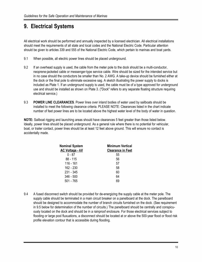
9.1 When possible, all electric power lines should be placed underground.
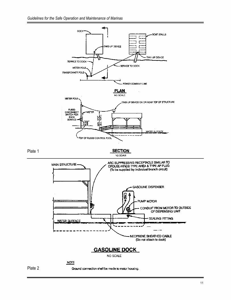
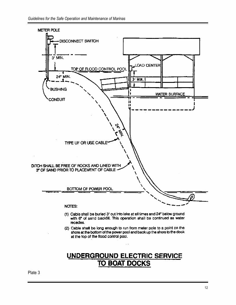
9.2 If an overhead supply is used, the cable from the meter pole to the dock should be a multi-conductor,neoprene-jacketed cable or messenger-type service cable. Wire should be sized for the intended service butin no case should the conductors be smaller than No. 2 AWG. A take-up device should be furnished either atthe dock or the final pole to eliminate excessive sag. A sketch illustrating the power supply to docks isincluded as Plate 1. If an underground supply is used, the cable must be of a type approved for undergrounduse and should be installed as shown on Plate 3. ("Dock" refers to any separate floating structure requiringelectrical service.)
9.3 POWER LINE CLEARANCES. Power lines over inland bodies of water used by sailboats should beinstalled to meet the following clearance criteria. PLEASE NOTE: Clearances listed in the chart indicatenumber of feet power lines are to be located above the highest water level of the body of water in question.
NOTE: Sailboat rigging and launching areas should have clearances 5 feet greater than those listed below. Ideally, power lines should be placed underground. As a general rule where there is no potential for vehicular, boat, or trailer contact, power lines should be at least 12 feet above ground. This will ensure no contact is accidentally made.
Nominal System Minimum VerticalAC Voltage - kV Clearance in Feet
0 - 87 5588 - 115 56116 - 161 57162 - 230 58231 - 345 60346 - 500 64501 - 765 69
9.4 A fused disconnect switch should be provided for de-energizing the supply cable at the meter pole. Thesupply cable should be terminated in a main circuit breaker on a panelboard at the dock. The panelboardshould be designed to accommodate the number of branch circuits furnished on the dock. (See requirementin 9.5 below for determination of the number of circuits.) The panelboard should be centrally and conspicu-ously located on the dock and should be in a rainproof enclosure. For those electrical services subject toflooding or large pool fluxuations, a disconnect should be located at or above the 500-year flood or flood riskprofile elevation contour that is accessible during flooding.
10
Guidelines for the Safe Operation and Maintenance of Marinas
11
Guidelines for the Safe Operation and Maintenance of Marinas
Plate 1
Plate 2
12
Guidelines for the Safe Operation and Maintenance of Marinas
Plate 3

9.5 Receptacles should be rated not less than 20 amperes and should be of the grounding type, mounted atleast 3 feet above the floor. Ground-fault circuit interrupters should protect 120-volt receptacles other thanthose supplying shore power to boaters. An individual branch circuit should supply each receptacle, whichsupplies shore power to boats. Also, receptacles supplying shore power should be rated not less than 20amperes and should be single and of the locking and grounding type. Convenience outlets provided forbattery charging and pumping small craft are not considered shore power. Outside receptacles should beweatherproof and installed in corrosion-resistant boxes having threaded hubs. Other circuits should bedesigned for the intended use, and individual branch circuits should be provided for all continuous loadsexcept lighting. The dock lighting fixtures should be so constructed and installed that water cannot enter oraccumulate in the lampholders or other electrical parts. The fixtures should be "Suitable for Damp (or Wet)Locations" as set out in the National Electrical Code. Each fixture should be mounted on a corrosion-resistant box equipped with a neoprene gasket and threaded hub. Fixtures should be mounted at least 7 feetabove walkways.
9.6 The following items should be grounded by a conductor and run with other circuit conductors:
a. Boxes, cabinets, and all other metallic enclosures.
b. Metal frames of utilization equipment (drink dispensing machines, ice machines, freezers, minnow vats,gasoline pumps, etc.).
c. Grounding terminals of receptacles (all receptacles should be grounding type).
d. All metal utilization equipment (drink dispensing machines, minnow vats, gasoline pumps, etc.) that aresupplied with electric power should be solidly grounded to prevent electric shock.
9.7 All dock wiring should be installed in conduit except non-metallic sheathed cable approved for continuousflexibility and wiring installed in areas that are inaccessible, such as above ceilings and in dry walls. Conduitmay be galvanized steel, PVC, or electrical metallic tubing.
9.8 The meter pole location should be such that the meter and pole-mounted service equipment are installed atleast 3 feet above the top of the high water level and accessible during high water events.
9.9 Minimum wire size should be: No. 2 AWG for service conductors, No. 8 AWG for feeder conductors, and No. 12 AWG for branch circuit conductors.
9.10 Special care should be employed in the wiring of gasoline dispensing pumps. In cases where a separate (or separable) gas dock is provided, the wiring for it should comply with the sketch shown as Plate 2. If thepumps are integral with the main dock, each circuit leading to the pumps should be provided with a switch todisconnect simultaneously from the source of supply all conductors of the circuit, including the groundedneutral. The switch should be readily accessible and in view of the pumps.
9.11 ELECTRICAL SIGNS. A special sign, stating the maximum voltage and current (in amperes) available fromthe shore service connection outlets should be permanently located at the shore end of each pier on whichelectrical outlets for shore service connections are provided, and on a wall visible to all within the officewhere arrangements are made for berthing facilities. Each such sign should contain the following additionalmessage in large letters:
13
Guidelines for the Safe Operation and Maintenance of Marinas
"CAUTION"
"CONNECTION SHALL NOT BE MADE TO ANY SHORE POWER OUTLET WITHOUT PERMISSION OF THE MANAGEMENT"
9.12 Exposed light bulbs should be covered or guarded.
9.13 Lighting sufficient for the anticipated activities should be provided for all marina areas but should be lowintensity and pointed in a downward direction to prevent interference with boat navigation.
9.14 Marina electrical systems should be inspected annually by a licensed electrician.
10. Grounding
10.1 Effective grounding of all non-current carrying metal parts of the electrical system, and provision of suitableequipment grounding facilities at all outlets provided for the connection of portable equipment, includingoutlets provided for the connection of shore power to vessels afloat, are of utmost importance in marinas,boatyards, boat basins, and similar establishments. This is due to the exposure of electrical systems andequipment to water, damp or wet earth, and to other grounded or partially grounded conductive parts andthe consequent danger to life and possibility of high energy sparking adjacent to combustible materials.
10.2 A grounding conductor separate from the neutral conductor of the electrical service should be installed withthe service conductors and connected to a suitable grounding electrode on the shore. This groundingconductor should be terminated in the distribution panelboard on the dock to provide positive grounding.
10.3 The method of providing an effective ground to the non-current-carrying metal parts of the electrical system,and for equipment and portable appliances connected thereto, should comply with the requirements of theNational Electrical Code.
10.4 In addition to the grounding provided by the conduit system, there should be installed a common groundingconductor of not less than No. 14 AWG arranged in accordance with the requirements of the NationalElectrical Code, properly attached to the interior of all metallic boxes, housings, and enclosures and properlyconnected to the grounding facility of the receptacle. Said grounding conductor should terminate at the distribution panel ground.
10.5 The partial or complete burial of a metal enclosure in earth is not accepted as a substitute for the groundingrequirements listed above.
10.6 In any slip or berthing space where metal hulls are stored or berthed, an anode of suitable material andcapacity connected to the equipment ground conductor of the electrical system should be suspended in thewater.
10.7 Portable power tools should be double insulated and only used with ground fault circuit interrupter (GFCI)protected circuits.
14
Guidelines for the Safe Operation and Maintenance of Marinas

11. Walkways
11.1 Main walkways should not be less than 4 feet wide. The minimum width between berthing slips should notbe less than 3 feet when used as access to boats.
11.2 Walkways should be kept free from mud, ice, snow, grease, or any other material or obstruction that couldcreate a slipping or tripping hazard.
11.3 Walkways should be structurally sound. Flooring or decking should not be less than 1-inch rough, 2 inch by6 inch S3S, 3/4 inch exterior plywood, or other material capable of supporting a minimum design load of 50pounds per square foot.
11.4 Walkways should be even, free from protruding bolts and nails, and have a slip-free surface. Carpetingshould not be used to provide a non-slip surface.
11.5 Walkways from shore-to-dock should have a maximum slope of 3 to 1; be free from excessive spring,deflection, and lateral movement; and be adequately supported with flotation.
11.6 Walkways should be above the water level at all times.
11.7 Shore-to-dock walkways should have a standard 42-inch high solid handrail with an intermediate rail securely installed on each side.
11.8 Where feasible, walkways from shore-to-dock should be constructed to allow access by the handicapped.
11.9 Accessways should be adequate for fighting fire as determined by local firefighting personnel.
11.10 Marinas at the beginning at the access walkway should be signed to prohibit swimming, diving, and running.Additionally emergency contact numbers should be posted.
11.11 Where security is an issue, a gate system to prevent unwelcome visitors, trespassers, and wanderingchildren should be provided.
12. Handrails
12.1 Handrails should be provided on all stairways, walkways, and all office and service docks that are open tothe general public.
12.2 Handrails should be 42 inches in height, with an intermediate rail approximately 22 inches in height. Wherechildren may be present, a guard between the deck and the lower rail is recommended.
12.3 Handrails must be capable of withstanding loads of 200 pounds applied in any direction at any point with aminimum of deflection. They must be structurally sound, maintained in a state of good repair, and a
15
Guidelines for the Safe Operation and Maintenance of Marinas
minimum size of 2 inch by 4 inch S4S, or equivalent strength material. Posts for handrails should be spacedon no more than 8-foot centers. Handrails should be smooth-surfaced with no protruding upright posts.
12.4 Stairways and walkways from shore-to-dock should have handrails on each side of the stairway or walkway.
12.5 Office and service docks should have handrails around the outside perimeter of the dock with appropriateopenings for boarding and fueling boats. Handrails are required where public exposure warrants them. Forexample, places on the dock where people tend to congregate or where the walkway is so narrow that twopeople carrying gear could not pass each other safely should have handrails. Also, handrails are requiredwhere walkways end or make sharp turns that would lead people to walk directly into the water. Handrailsare required at the main walkway end of boat storage stalls whenever the dock layout requires shore visitorsto pass these openings on their way to other public use facilities.
12.6 Gates and signs should be installed to limit access to boat storage and repair areas to authorized personnelonly.
13. Throwable Lifesaving Devices and First Aid
13.1 At least one throw-type lifesaving device with 60 feet of 3/8-inch diameter rope attached and/or a reach poleshould be available on each dock. On docks more than 200 feet long, one device should be located every200 feet along the dock. Rope should be made of polypropylene or some other floating material.
13.2 A minimum of one, 16-unit first aid kit should be available at each marina.
14. Housekeeping
14.1 Maintenance and operating practices should be in accordance with established procedures to control leakage and prevent accidental escape of flammable or combustible liquids. Spills should be cleaned up promptly.
14.2 Adequate aisles should be maintained for unobstructed movement of personnel and fire protection equipment.
14.3 Combustible waste material and residues in a building or unit operating area should be kept to a minimum, stored in covered metal receptacles, and disposed of daily.
14.4 Ground areas around buildings and unit operating areas should be kept free of weeds, trash, or other unnecessary combustible materials.
14.5 All floors should be covered with a slip-free surface and kept free of any tripping or slipping hazard. Loose orrotten boards should be repaired or replaced.
16
Guidelines for the Safe Operation and Maintenance of Marinas

14.6 The entire marina area should be kept neat and clean with equipment properly stored so it does not poseany type of safety hazard to the public or marina employees.
15. Sewage Management
15.1 Each marina should have a sewage management plan that is in compliance with all federal, state, and localwastewater outfall and septic system requirements.
15.2 Marinas should be designated as "no sewage discharge" areas, and sewage discharge should be prohibitedwithin the marina basin.
15.3 Marinas should provide a pumpout system (fixed point system, portable/mobile system, or dedicated slipsidesystem) that meets the needs of the marina users at either a free or reasonable cost.
15.4 The marina should have a dump station or wand attachment to the pumpout system to empty portable toilets.
15.5 Pumpout stations should be clean and easily accessible and/or have marina staff to perform pump outs.
15.6 Sewage facilities should be regularly inspected and maintained.
15.7 Marinas should prohibit the use of y-valves on marine sanitation devices (MSDs).
15.8 Marinas should maintain a sign-in sheet for users of pumpout stations.
15.9 Marinas should have clean, functioning restrooms available 24 hours per day.
17
Guidelines for the Safe Operation and Maintenance of Marinas

18
Guidelines for the Safe Operation and Maintenance of Marinas

Appendix A: Minimum Design Criteria for Fixed and Floating Structures
NOTE: Design should meet all Americans with Disabilities Act (ADA) criteria.
1. FIXED STRUCTURES
A. As a minimum, fixed, covered facilities should be designed to prevent damage to stored boats by forcingthem against the roof during a 100-year flood event.
B. The floor elevation of fixed docks and piers should be a minimum of 2 feet above the normal high pool elevation.
2. FLOATING STRUCTURES
A. DESIGN CRITERIA.
1. Wood Material - When wood material is used, it should be designed in accordance with Chapter 25 ofThe Uniform Building Code, latest edition, as applicable. However, all connections should be securedwith galvanized sheet metal, steel plates, metal straps, or treated plywood gussets to resist movementthat would otherwise tend to dismantle the structural connections. All wood material in the substructure,including the deck, must be pressure treated with a non-skin-irritating preservative. Wood material in thesuperstructure should not require preservative treatment, but the exposed exterior should be painted withnot less than two coats of exterior oil paint.
2. Steel Material - When steel material is used, it should be designed to comply with Chapters 27 and 28 ofthe latest edition of the Uniform Building Code, as applicable, depending on the type of steel used.Welded or bolted connections are optional. New metal on the exposed exterior of the superstructure isdesired. Used steel may be adequate if it is in good condition; however, if the used steel is of a dull color,application of paint may be required.
3. Bracing - Wood or steel material or a combination thereof: All columns and studwalls should beadequately braced to resist windloads of at least 20 pounds per square foot. Bracing should be designedand constructed to counteract design loads. The structure should have sufficient flexibility whereby waveactions will not damage the structural or roof system.
B. DESIGN LOADS. (Minimum)
1. Deck loads (substructure) 50 lb/ft2
2. Approach bridges or walkways 50 lb/ft2
3. Windloads (substructures and superstructures) 20 lb/ft2
4. Roof loads (superstructures) 10 lb/ft2 (to provide for a 2-inch ice load or an equivalent amount of snow [where applicable]).
19
Guidelines for the Safe Operation and Maintenance of Marinas
5. Flotation must be provided under all areas of the substructure having 25 square feet or greater.
C. SIDING ON SUPERSTRUCTURE. Siding on the superstructure may consist of wood, corrugated orflat galvanized steel, or corrugated or flat aluminum.
D. ROOFS. (superstructure)
1. Roofs may be gabled or non-sloped.
2. Wood roof joists or rafters should not be less than 2 inches by 5 inches and spaced not more than 2 feetcenter-to-center. Consideration should be given to 4-foot spacing where sufficient vertical supports andbracing are provided. Purlins should be not less than 2 inches by 4 inches and spaced not more than 30inches center-to-center.
3. Wood roofs must consist of 1 inch nominal tongue and groove, shiplap or 1/2-inch plywood sheathingcovered with 30 pound asphalt roll roofing, or asphalt shingles. (When asphalt shingles are used, theroof slope must be 4 on 12 or steeper.)
4. Metal roof joists or rafters should not be less than 1-1/4 inch ID standard pipe or structural aluminumtubing, either round, square, or rectangular and spaced not more than 2 feet center-to-center.Consideration should be given to 4-foot spacing where sufficient vertical supports and bracing areprovided. Purlins should not be less than 1-inch ID pipe or structural aluminum tubing and spaced notmore than 2 feet center-to-center. Other standard steel or structural aluminum shapes may be adequateif designed for the minimum design loads.
5. Metal roofs should be steel, with a minimum gauge of 28, or aluminum with a minimum thickness of0.032 inch.
6. Roofs should be securely fastened to the superstructure to resist wind uplift.
E. WOOD CONSTRUCTION.
1. Floor joists and flotation frames should be not less than 2 inch by 8 inch, and stringers should notexceed 24 inches center-to-center.
2. Framing for wood columns should be no less than 4 inches by 4 inches and/or double 2 inches by 4inches, spaced no more than 4 feet center-to-center, or 2 inches by 4 inches, spaced no more than 2feet center-to-center. Subject to the stability of the roof structure, including adequate bracing, the 4-inchby 4-inch vertical supports may be spaced up to 8 feet on centers. Columns should in every case bespaced symmetrically on each side of the walkway equal to their width. Flooring or decking should not beless than 1-inch rough or 2 inches by 6 inches S45 material and spaced to allow for expansion. Concreteor similar flooring types and decking are allowable. Wood columns will be bolted through a 4-inchdimension to 2 inches by 8 inches stringers or flotation frames.
F. METAL CONSTRUCTION.
1. Floor joists and flotation frames should not be less than 2 inches ID standard pipe. Other standard structural steel sections are acceptable.
20
Guidelines for the Safe Operation and Maintenance of Marinas

2. Framing for pipe construction should be no less than 1-1/4 inch H7 standard pipe or structural aluminum,round, square or rectangular tubing. Studs should not exceed 48 inches center-to-center. Other standardsteel or structural aluminum sections are acceptable.
G. WALKWAYS.
1. Walkways should be not less than 3 feet wide and structurally sound.
2. Flotation material should be determined on length of walkway in the water and/or connections on thefloating craft and the shore.
3. The method of anchoring the walkway to the floating structure and the shore should allow for adequatewater level fluctuations and should not create a tripping hazard.
H. STABILIZED OR UNDERWATER BRACE.
1. A stabilized or underwater metal brace is recommended on the front (lake side) of a boat house betweendock walkways.
2. The size of the metal brace should be determined on the width between the dock walkways.
3. The depth of the metal brace below the water line should be determined on the draft of the floating craftto be stored in the boat house.
I. FLOTATION. Flotation should be of materials fabricated for marine use. The flotation material should beexpanded, encased, or encapsulated and 100 percent warranted for a minimum of 8 years against sinking,becoming waterlogged, cracking, peeling, fragmenting, or losing beads. All flotation material should resistpuncture and penetration and should not be subject to damage by animals under normal conditions for thearea. All flotation material should be fire resistant. Use of new or recycled plastic or metal drums or non-compartmentalized air containers for encasement should be prohibited.
J. MARINE MARKINGS. Aids to navigation in and around marinas should be consistent with U.S. Aids toNavigation.
21
Guidelines for the Safe Operation and Maintenance of Marinas

22
Guidelines for the Safe Operation and Maintenance of Marinas
Appendix B: Recommended Safeguards for Installation of Underground Tanks
** Performance standards for new underground storage tanks may be found in the Code of Federal Regulations,Title 40-Protection of Environment, Chapter I-Environmental Protection Agency, Subchapter I-Solid Wastes, Part280-Technical Standards and Corrective Action Requirements for Owners and Operators of Underground StorageTanks (UST), Subpart B-UST Systems: Design, Construction, Installation, and Notification.
1. The design, construction, and use of storage tanks whose capacity exceeds 660 gallons should be asspecified in Section 2 of NFPA 30, Flammable and Combustible Liquids Code.
2. Underground tanks provide a widely accepted method for storage of flammable and combustible liquids.Such storage is frequently under buildings or driveways, permitting other uses of the area above the tanks.In all cases tanks should be located above the maximum water level elevation.
3. These liquids in underground tanks seldom become involved in fires even when buildings above them burnto the ground. However, when a tank is buried, it is not like an aboveground tank, accessible for inspection,maintenance, and painting.
4. The labor of replacing an underground tank is often much greater than the cost of installation of the originaltank or the value of the replacement tank. Therefore, securing maximum leak-free life from a tank is goodeconomics. The entrance of water into a tank, or leakage of product out of a tank or its connected piping,can also cause serious economic loss and possible hazards to adjacent property.
5. Because visual inspection of underground tanks is impossible, minor leaks may go undetected for sometime, particularly if inventory control is inadequate. Small quantities, which might evaporate harmlesslyabove ground, may be protected from evaporation by ground cover. In well drained areas, such liquidsusually dissipate harmlessly. However, where a high water table exists, or where the liquid follows natural orsewer drains, underground piping or conduits escaping liquid may travel some distance underground.
6. A low flash point flammable liquid may create a hazard if it enters a basement, utility manhole, or similarsubgrade enclosure where vapors may accumulate and a source of ignition may exist. Fortunately, inoccupied premises these vapors usually manifest themselves by odor at concentrations below the flammablerange.
7. Fire prevention and economics both require high standards of fabrication and installation to extend the life ofthe tank and to prevent leakage. Therefore, operating methods that will detect leaks promptly should beemployed. Reliable methods for locating the source of spillage or leakage should be employed, and respon-sibility for each investigation should be established. An effective and safe method should be used for testingeach individual tank suspected of leaking.
23
Guidelines for the Safe Operation and Maintenance of Marinas

24
Guidelines for the Safe Operation and Maintenance of Marinas
Appendix C: Sample Marina Inspection Checklists
These checklists are not all inclusive, will not be specifically applicable to all marinas, and are included forinformation only.
SAMPLE MARINA SELF INSPECTION CHECKLISTGENERAL APPEARANCE# YES NO N/A ITEM1 Is the facility attractive?2 Is the facility well organized?3 Is the facility neat and tidy?4 Is the facility well maintained?
SANITATION# YES NO N/A ITEM5 Is trash picked up and in proper containers?6 Is refuse/trash removed daily?7 Are restroom facilities clean and maintained?8 Are outlets for non-potable water supply posted clearly?
ACCESS# YES NO N/A ITEM9 Are all ramps, docks, and decks (excluding fingers) at least 36 wide?10 Do stairs with more than 4 steps have handrails?I1 Are gangways protected by guardrails?12 Are nails and screws recessed or flush with the surface?13 Is planking laid close together? (Gaps no more than 3/8 inch)14 Is planking braced? (No excess springiness)15 Are tripping hazards marked yellow?16 Are warning signs placed on public hazards?17 Where dock sections join, are they securely lashed/fastened?18 Are accessways free of materials, obstructions?19 Are dock anchor cables identified if they are hazardous?
ELECTRICAL# YES NO N/A ITEM20 Switches, fuses, circuit breakers marked and labeled?21 Is grounding provided for non-current carrying metal parts?22 Are outdoor switches, circuit breakers,
and panel boxes in weatherproof enclosures?23 Do portable and semi-portable electrical tools and equipment
have a conductor cord with a ground plug(except for UL/FM approved double insulated tools)?
24 Is a ground fault circuit interrupter (GFCI) provided on all non-permanent 120 volt 15/20 amp receptacles?
25 Is there a designated separate battery charging station?26 Does an extension cord run items that are supposed to be hard-wired?
25
Guidelines for the Safe Operation and Maintenance of Marinas

ELECTRICAL (Cont’d)# YES NO N/A ITEM27 Are there any frayed cords or wires?28 Are boats permanently connected when they're not supposed to be?29 Are permanently connected boats using a power cord?30 Are permanently connected boats using a proper outlet?3l Are there any cords that can be walked on, driven over,
or chafed by boat or dock movement?32 Is there any unknown wiring coming from boxes?33 Are there any damaged or inoperative switches, lighting fixtures,
or receptacles?34 Is electrical certification current?
INSPECTION FOR THE MONTHOF_________________________________________________________________YEAR____________________
FACILITY_____________________________________________________________________________________
INSPECTED BY ______________________________________________________DATE____________________
REVIEWED BY _______________________________________________________DATE____________________
APPROVED BY _______________________________________________________DATE___________________
EMERGENCY/FIRST AID# YES NO N/A ITEM35 Is at least one 16-unit first aid kit provided?36 Are emergency numbers posted?
WATER SAFETY# YES NO N/A ITEM37 Is there a throwable (Type IV ) PFD available at intervals
of not more than 60 m (200 ft) on walkways?38 Do ring buoys have at least 21 m (70 ft) of 1 cm (3/8 inch) solid braid
polypropylene line attached?39 Is the maximum capacity posted on each boat?40 Are the boat capacity levels sufficient for stability when loaded?41 Is a wearable PFD (Type I, II, III, or V) provided for each passenger?42 Is a throwable (Type IV) PFD provided for each boat?
FIRE PROTECTION# YES NO N/A ITEM43 Are NO SMOKING signs posted in areas where there are flammables?44 Is a fire plan posted?45 Are pay telephones accessible and marked?46 Are portable fire extinguishers readily available and provided where needed?47 Are portable fire extinguishers distinctly marked?
26
Guidelines for the Safe Operation and Maintenance of Marinas

FIRE PROTECTION (Cont’d)# YES NO N/A ITEM48 Are portable fire extinguishers fully charged?49 Are portable fire extinguishers checked monthly for charge,
mud dauber nests, and loose powder?50 Is staff trained in fire extinguisher use?51 Are portable fire extinguishers examined yearly?52 Are spare/replacement extinguishers available?53 Are all rags/waste soiled by oil/grease disposed of daily in
tight-closing UL cans?54 Are exhaust pipes from heating systems insulated where
they pass through roofs or walls?55 Are drums/barrels/containers of flammable liquids stored properly?56 Are flammable liquids/gas storage tanks grounded and bonded?57 Do flammable liquid dispensing outlets have quick-closing/self-closing valves?58 Are portable flammable liquid containers UL approved?59 Liquid propane systems do not have aluminum or PVC tubing.
GENERAL# YES NO N/A ITEM60 Are parking areas delineated and laid out to prevent traffic congestion?61 Are parking spaces on sloping terrain provided with barriers to prevent rolling?62 Are guardrails 42 inches high?63 Are moving parts of equipment guarded to prevent pinching?64 Is adequate lighting provided for operations that run into hours of darkness?
SUGGESTED ELECTRICAL INSPECTION CHECKLIST INCOMING SERVICE LINEYES NO N/A ITEM
Clearance > 12 ft. - walksClearance > 18 ft. - roadsClear of trees/limbsApproved conductors
SERVICE POLEYES NO N/A ITEM
3' above top datum planeGuy wire tightYellow cover on guy wire (marking it as a hazard)In Weather Head/ConduitBelow 8' above groundApproved drip loopConduit secured < 3'/10'Panel/Switch secured and cleanWeatherproof/sealed (NEMA 4 or 3R type Encl)Panel grounded properly with ground lug (#8 CU/#6 AL to Ground Rod)Ground Rod installedBushings installed A/RProper OperationLugs (AL/CU labeled) for AL wire
27
Guidelines for the Safe Operation and Maintenance of Marinas

DOCK FEEDERYES NO N/A ITEM
Clearance > 12 ft. - walksClearance > 18 ft. - roadsClearance > 55 ft. - sailsClearance > 18 ft. - boatsWith barriers < 12 feet - water (consider party barges w/antenna & running lights raised) Take-up reel/weather headRoof penetration sealedBusing at roof and panel entrancesGuy wire/supports tightConductors Quadplex (3 insulated conductors)Conductors #8 CU/#6 AL min.In conduit < 24" burial to 3" below power/navigation pool?Conduit is "RIGID" type (RGS, schedule 40/80 PVC) stamped on conduitConduit secured < 3" of all unions, panels, boxes, fittings and 10' Min.Underwater feeder secured by Kellums Grips or other approved grip to dock structureFeeder in conduit where exposed to damageBushings installed at conduit J-box entry point, sealed, waterproofCheck for damaged insulationFlex conduit is sealtight/waterproof type
EXTENSION/FLEXIBLE CORDSYES NO N/A ITEM
Hard to Extra Hard usageNot in waterNot across roadwaysNot across sharp objectsNot across walkways
DOCKYES NO N/A ITEM
Panel properly secured and clean insideCircuit breakers secured to bus barsConnections tight (AL will creep and work loose)Circuit breakers labeled clearly (numbered IAW legend)Panel to elevation < 6' 6" above deckPanel enclosure NEMA 4 or NEMA 3R rated weatherproofUnused openings sealed with plugs or silicone sealantNo openings larger than 1/8"Wiring in conduit (new docks)Proper bushingsWiring < 8' above deck (old docks)Insulated staples @ 4 ½' intervalsDevices and panels secured to sound structure of dockConduit secured < 3' of all unions, panels, boxes, fittings and 10' minConduits secured to panels and boxes tightly for electrical bonding/continuity.
28
Guidelines for the Safe Operation and Maintenance of Marinas

DOCK (Cont’d)YES NO N/A ITEM
Double lock nuts (required for EMT)Rigid and IMC threaded.Lights minimum of 8' above deckLights with guard and globeLights UL listed for damp/weatherproofLight gasketedBulbs not brokenLights clear of flammable members (12" incandescent, 6" fluorescent)Outlet boxes containing receptacles, switches, lights must be secured to structureJ boxes must be secured to threaded conduit (IMC or Rigid)For EMT and Flex, J-Boxes secured to the structureReceptacles/switches > 30" elevation above water and 12" above deckConductors-three to each device: hot, neutral and ground -"EGC"Bushings installed A/R - Check for conductors in contact with sharp edges of conduit or panelsConductors not skinned or cracked and in good conditionConductor insulation approved for damp or wet locations (THW, THHN, THWN)Conduit supports UL approved nails, straps not allowed in most cases)Boxes NEMA 4 weatherproof/drip proof NEMA 3R (No boxes with knockouts)Receptacles properly grounded (check for pigtail ground to box or continuity device on yoke)Receptacles or Circuit Breakers equipped with GFCI's (Test or reset button on the device)Receptacles equipped with weatherproof covers (must be closed when unattended unless rated)
29
Guidelines for the Safe Operation and Maintenance of Marinas


