I:\SDC\04\WP\SDC 4-WP 5 (E).docx E SUB-COMMITTEE ON SHIP DESIGN AND CONSTRUCTION 4th session Agenda item 12 SDC 4/WP.5 15 February 2017 Original: ENGLISH GUIDELINES FOR USE OF FIBRE REINFORCED PLASTIC (FRP) WITHIN SHIP STRUCTURES Report of the Working Group on Fire Protection General 1 The Working Group on Fire Protection met from 13 to 15 February 2017 under the chairmanship of Mr. G. Szemler (Sweden). 2 The group was attended by delegations from the following Member States: BAHAMAS BELGIUM BRAZIL CANADA CHINA DENMARK FINLAND FRANCE GERMANY INDONESIA IRAN (ISLAMIC REPUBLIC OF) ITALY JAPAN LIBERIA MARSHALL ISLANDS NETHERLANDS NORWAY PERU PHILIPPINES REPUBLIC OF KOREA RUSSIAN FEDERATION SINGAPORE SWEDEN TURKEY UNITED KINGDOM UNITED STATES observers from the following intergovernmental organization: EUROPEAN COMMISSION (EC) and observers from the following non-governmental organizations in consultative status: INTERNATIONAL CHAMBER OF SHIPPING (ICS) INTERNATIONAL ASSOCIATION OF CLASSIFICATION SOCIETIES (IACS) COMMUNITY OF EUROPEAN SHIPYARDS' ASSOCIATIONS (CESA) ROYAL INSTITUTION OF NAVAL ARCHITECTS (RINA) INTERNATIONAL TRANSPORT WORKERS' FEDERATION (ITF)
Transcript
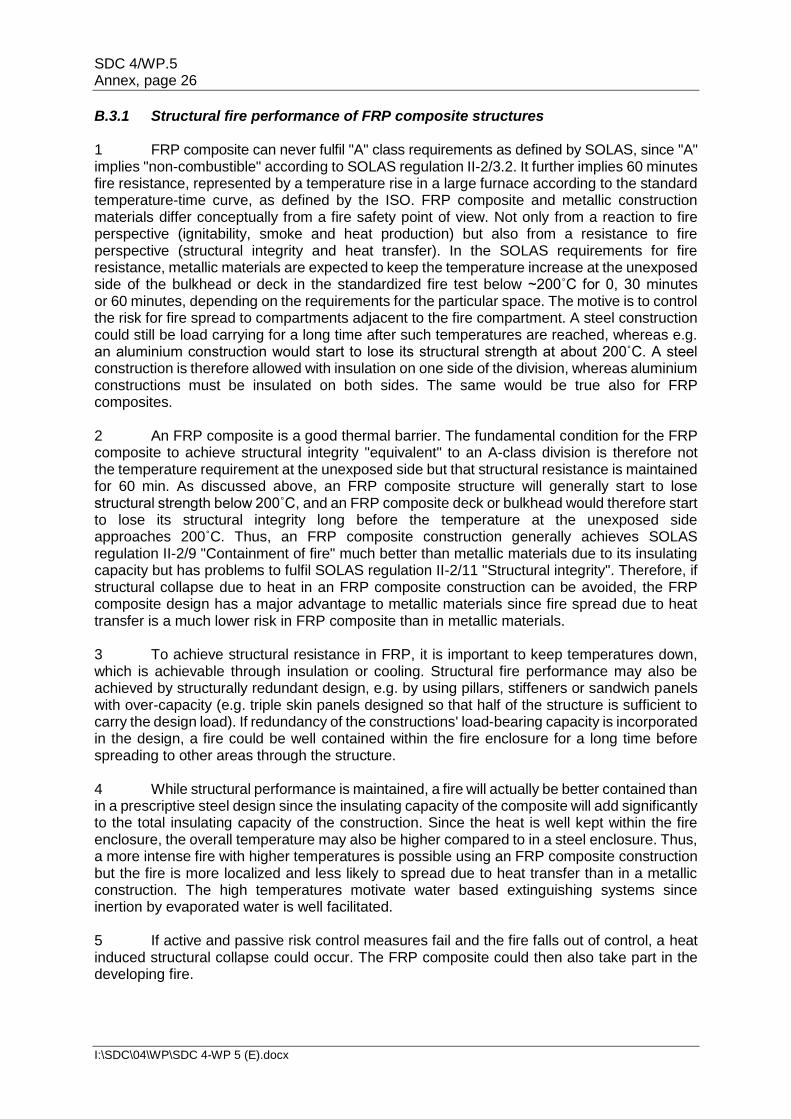
I:\SDC\04\WP\SDC 4-WP 5 (E).docx
E
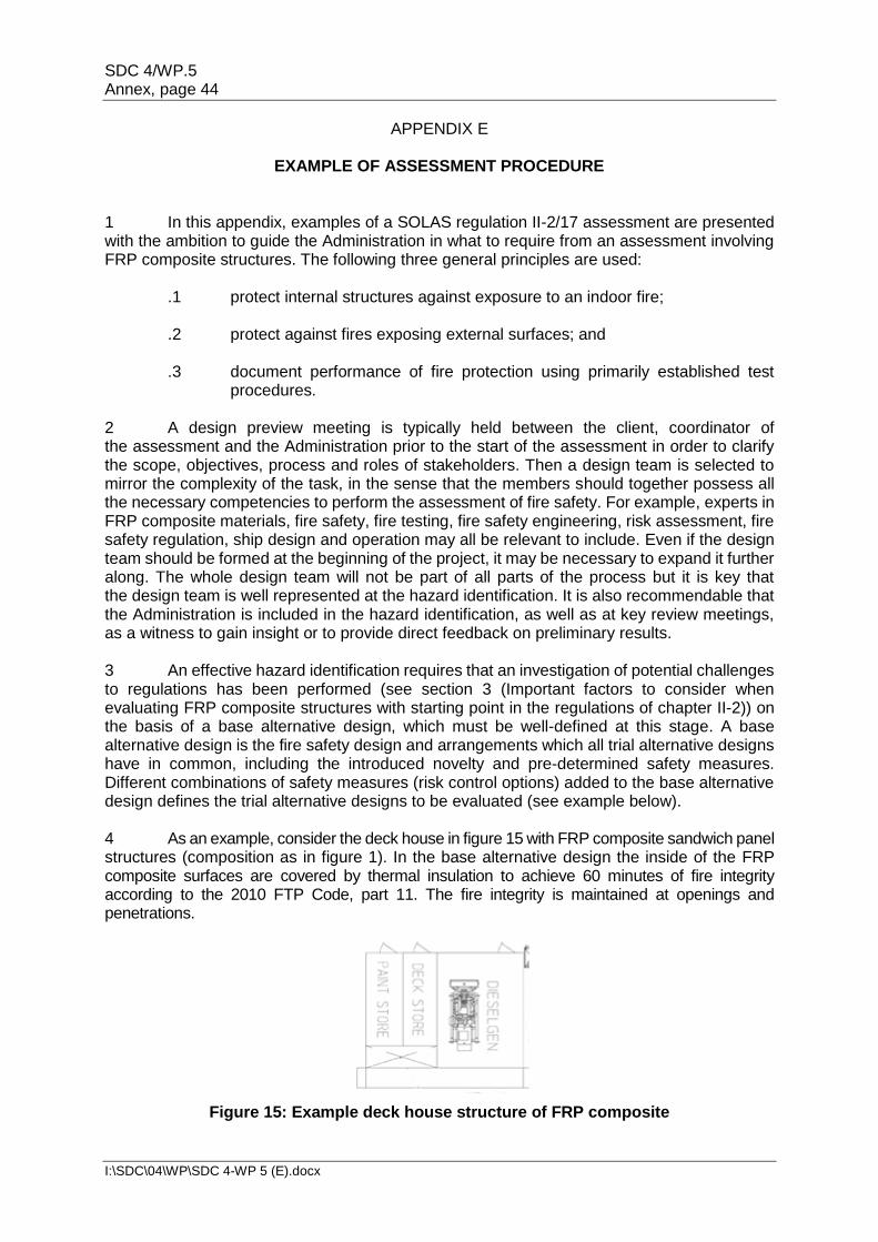
SUB-COMMITTEE ON SHIP DESIGN AND CONSTRUCTION 4th session Agenda item 12
SDC 4/WP.5
15 February 2017 Original: ENGLISH
GUIDELINES FOR USE OF FIBRE REINFORCED PLASTIC (FRP)
WITHIN SHIP STRUCTURES
Report of the Working Group on Fire Protection
General
1 The Working Group on Fire Protection met from 13 to 15 February 2017 under the chairmanship of Mr. G. Szemler (Sweden).
2 The group was attended by delegations from the following Member States:
BAHAMAS BELGIUM BRAZIL CANADA CHINA DENMARK FINLAND FRANCE GERMANY INDONESIA IRAN (ISLAMIC REPUBLIC OF) ITALY JAPAN
LIBERIA MARSHALL ISLANDS NETHERLANDS NORWAY PERU PHILIPPINES REPUBLIC OF KOREA RUSSIAN FEDERATION SINGAPORE SWEDEN TURKEY UNITED KINGDOM UNITED STATES
observers from the following intergovernmental organization:
EUROPEAN COMMISSION (EC) and observers from the following non-governmental organizations in consultative status:
INTERNATIONAL CHAMBER OF SHIPPING (ICS) INTERNATIONAL ASSOCIATION OF CLASSIFICATION SOCIETIES (IACS) COMMUNITY OF EUROPEAN SHIPYARDS' ASSOCIATIONS (CESA) ROYAL INSTITUTION OF NAVAL ARCHITECTS (RINA) INTERNATIONAL TRANSPORT WORKERS' FEDERATION (ITF)
SDC 4/WP.5 Page 2
I:\SDC\04\WP\SDC 4-WP 5 (E).docx
Terms of reference 3 Taking into account the comments made and decisions taken in plenary, the working group was instructed to:
.1 finalize the draft Interim guidelines for use of Fibre Reinforced Plastic (FRP)
elements within ship structures and the associated draft MSC circular, based on the annex to document SDC 4/12, taking into account document SDC 4/12/1; and
.2 submit a written report by Thursday, 16 February 2017.
Definition of the term "element" 4 The group considered the definition of the term "element" and the text in square brackets in paragraph 1.2 of the draft Interim guidelines for use of Fibre Reinforced Plastic (FRP) elements within ship structures (draft Interim guidelines) (SDC 4/12, annex). Following discussion, the group agreed to the following amended definition:
"An element, for the purpose of these guidelines, is a structure which may be removed without compromising the safety longitudinal strength of the ship." (annex, paragraph 1.3).
5 The group also agreed to insert a new paragraph immediately under the definition of the term "element", highlighting that safety-critical spaces (e.g. control stations, evacuation stations and escape routes) should be given special consideration (within the assessment) if the use of FRP elements was being considered (annex, paragraph 1.4). Categories of FRP elements 6 The group extensively discussed the proposal in paragraph 6 of document SDC 4/12/1 regarding structures below and above the main deck, in conjunction with the categorization of FRP elements, as set out in the second set of square brackets in paragraph 1.2 of the draft Interim guidelines (SDC 4/12, annex). 7 Several attempts were made to clarify the term "main deck". Although there was a common understanding that in simple cases the main deck was to be understood as the strength deck, freeboard deck or bulkhead deck, the group acknowledged that the aforementioned understanding did not hold for certain types of ships (e.g. ro-ro and passenger ships) where several decks above the bulkhead deck contributed by various degrees to the structural integrity and the strength of the ship. Furthermore, there were divergent opinions as to what types of structures above the main deck could be considered. 8 The group agreed that the list of FRP element categories was intended to provide examples of some of the possible FRP element categories that could be considered when applying the Interim guidelines, rather than a complete and fixed enumeration of categories. In this context, taking into account the difficulties in reaching a consensus with regard to the first category (i.e. "structures"), the group further agreed to list two categories (i.e. "integrated structures" and "components") rather than three in the penultimate paragraph of chapter 1 of the draft Interim guidelines (annex, paragraph 1.7), separate from the definition of the term "element", with the understanding that during a future review the list of categories could be refined and/or expanded, based on experience gained from the use of the Interim guidelines.
SDC 4/12 Page 3
I:\SDC\04\WP\SDC 4-WP 5 (E).docx
Additional tests 9 Having considered the small-scale "Purser Furnace" method for FRP, the group concluded that the test was not suitable for FRP and agreed to delete paragraph 3 of section D.8 in appendix D, set out in the annex to document SDC 4/12. Timeframe for the review of the Interim guidelines 10 Having recalled that the Sub-Committee had agreed to propose to the Committee to keep the output on "Guidelines for use of Fibre Reinforced Plastic (FRP) within ship structures" on its post-biennial agenda, the group agreed that four years was a suitable period, following the approval of the Interim guidelines, allowing Administrations to gather experience in the use of the Interim guidelines with a view to reviewing them. The group modified paragraph 4 of the associated draft MSC circular accordingly and invited the Sub-Committee to endorse the group's recommendation in this regard. 11 In this context, the group further modified the draft MSC circular to include a paragraph inviting Member States and international organizations to submit information, observations, comments and recommendations based on the practical experience gained through the application of the Interim guidelines to the Sub-Committee under the agenda item "Any other business". Finalization of the draft Interim guidelines 12 To finalize the draft Interim guidelines, the group reviewed the draft text set out in the annex to document SDC 4/12 and, after making minor modifications and editorial corrections, prepared a final clean version of the Interim guidelines and the associated draft MSC circular, as set out in the annex, for consideration by the Sub-Committee. Action requested of the Sub-Committee 13 The Sub-Committee is invited to approve the report in general and, in particular, to: .1 endorse the group's recommendation that four years was a suitable period
for Administrations to gather experience in the use of the Interim guidelines for use of Fibre Reinforced Plastic (FRP) elements within ship structures: Fire safety issues, with a view to reviewing them (paragraph 10 and annex); and
.2 endorse the draft Interim guidelines for use of Fibre Reinforced Plastic (FRP)
elements within ship structures and the associated draft MSC circular, for submission to MSC 98 for approval (paragraph 12 and annex).
***
SDC 4/WP.5 Annex, page 1
I:\SDC\04\WP\SDC 4-WP 5 (E).docx
ANNEX
DRAFT MSC CIRCULAR
INTERIM GUIDELINES FOR USE OF FIBRE REINFORCED PLASTIC (FRP) ELEMENTS WITHIN SHIP STRUCTURES: FIRE SAFETY ISSUES
1 The Maritime Safety Committee, at its [ninety-eighth session (7 to 16 June 2017)], having considered a proposal by the Sub-Committee on Ship Design and Construction at its [fourth] session, approved the Interim guidelines for use of Fibre Reinforced Plastic (FRP) elements within ship structures: Fire safety issues, as set out in the annex. 2 The annexed Interim guidelines should be used as a supplement to the Guidelines for the approval of alternatives and equivalents as provided for in various IMO instruments (MSC.1/Circ.1455) and the Guidelines on alternative design and arrangements for fire safety (MSC.1/Circ.1002, as amended by MSC.1/Circ.1552) when approving FRP elements within ship structures. 3 Member States are invited to apply the annexed Interim guidelines when approving alternative designs and arrangements for FRP elements in ship structures in accordance with SOLAS regulation II-2/17 (Alternative design and arrangements). The Interim guidelines are intended to ensure that a consistent approach is taken with regard to standards of fire safety of ships making use of FRP elements in their structures and that the level of fire safety afforded by the provisions of SOLAS chapter II-2 is maintained. 4 These guidelines have been issued as "interim guidelines" in order to gain experience in their use. They should be reviewed four years after their approval in order to make any necessary amendments based on experience gained. 5 In the meantime, Member States and international organizations are invited to submit information, observations, comments and recommendations based on the practical experience gained through the application of these Interim guidelines to the Sub-Committee on Ship Design and Construction under the agenda item "Any other business". 6 Member States are invited to bring the annexed Interim guidelines to the attention of all parties concerned.
SDC 4/WP.5 Annex, page 2
I:\SDC\04\WP\SDC 4-WP 5 (E).docx
ANNEX INTERIM GUIDELINES FOR USE OF FIBRE REINFORCED PLASTIC (FRP) ELEMENTS
WITHIN SHIP STRUCTURES: FIRE SAFETY ISSUES
Chapter 1 General
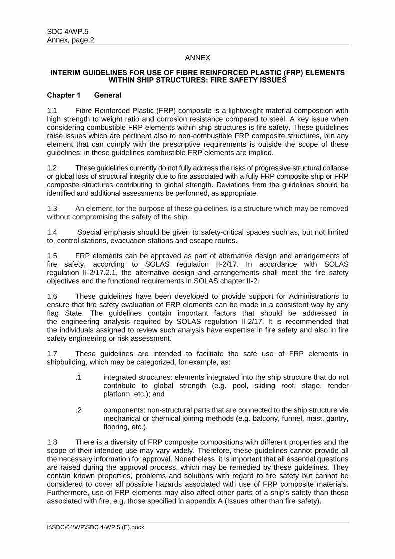
1.1 Fibre Reinforced Plastic (FRP) composite is a lightweight material composition with high strength to weight ratio and corrosion resistance compared to steel. A key issue when considering combustible FRP elements within ship structures is fire safety. These guidelines raise issues which are pertinent also to non-combustible FRP composite structures, but any element that can comply with the prescriptive requirements is outside the scope of these guidelines; in these guidelines combustible FRP elements are implied.
1.2 These guidelines currently do not fully address the risks of progressive structural collapse or global loss of structural integrity due to fire associated with a fully FRP composite ship or FRP composite structures contributing to global strength. Deviations from the guidelines should be identified and additional assessments be performed, as appropriate.
1.3 An element, for the purpose of these guidelines, is a structure which may be removed without compromising the safety of the ship.
1.4 Special emphasis should be given to safety-critical spaces such as, but not limited to, control stations, evacuation stations and escape routes.
1.5 FRP elements can be approved as part of alternative design and arrangements of fire safety, according to SOLAS regulation II-2/17. In accordance with SOLAS regulation II-2/17.2.1, the alternative design and arrangements shall meet the fire safety objectives and the functional requirements in SOLAS chapter II-2.
1.6 These guidelines have been developed to provide support for Administrations to ensure that fire safety evaluation of FRP elements can be made in a consistent way by any flag State. The guidelines contain important factors that should be addressed in the engineering analysis required by SOLAS regulation II-2/17. It is recommended that the individuals assigned to review such analysis have expertise in fire safety and also in fire safety engineering or risk assessment.
1.7 These guidelines are intended to facilitate the safe use of FRP elements in shipbuilding, which may be categorized, for example, as:
.1 integrated structures: elements integrated into the ship structure that do not contribute to global strength (e.g. pool, sliding roof, stage, tender platform, etc.); and
.2 components: non-structural parts that are connected to the ship structure via mechanical or chemical joining methods (e.g. balcony, funnel, mast, gantry, flooring, etc.).
1.8 There is a diversity of FRP composite compositions with different properties and the scope of their intended use may vary widely. Therefore, these guidelines cannot provide all the necessary information for approval. Nonetheless, it is important that all essential questions are raised during the approval process, which may be remedied by these guidelines. They contain known properties, problems and solutions with regard to fire safety but cannot be considered to cover all possible hazards associated with use of FRP composite materials. Furthermore, use of FRP elements may also affect other parts of a ship's safety than those associated with fire, e.g. those specified in appendix A (Issues other than fire safety).
SDC 4/WP.5 Annex, page 3
I:\SDC\04\WP\SDC 4-WP 5 (E).docx
Chapter 2 Assessing fire safety of FRP composite structures
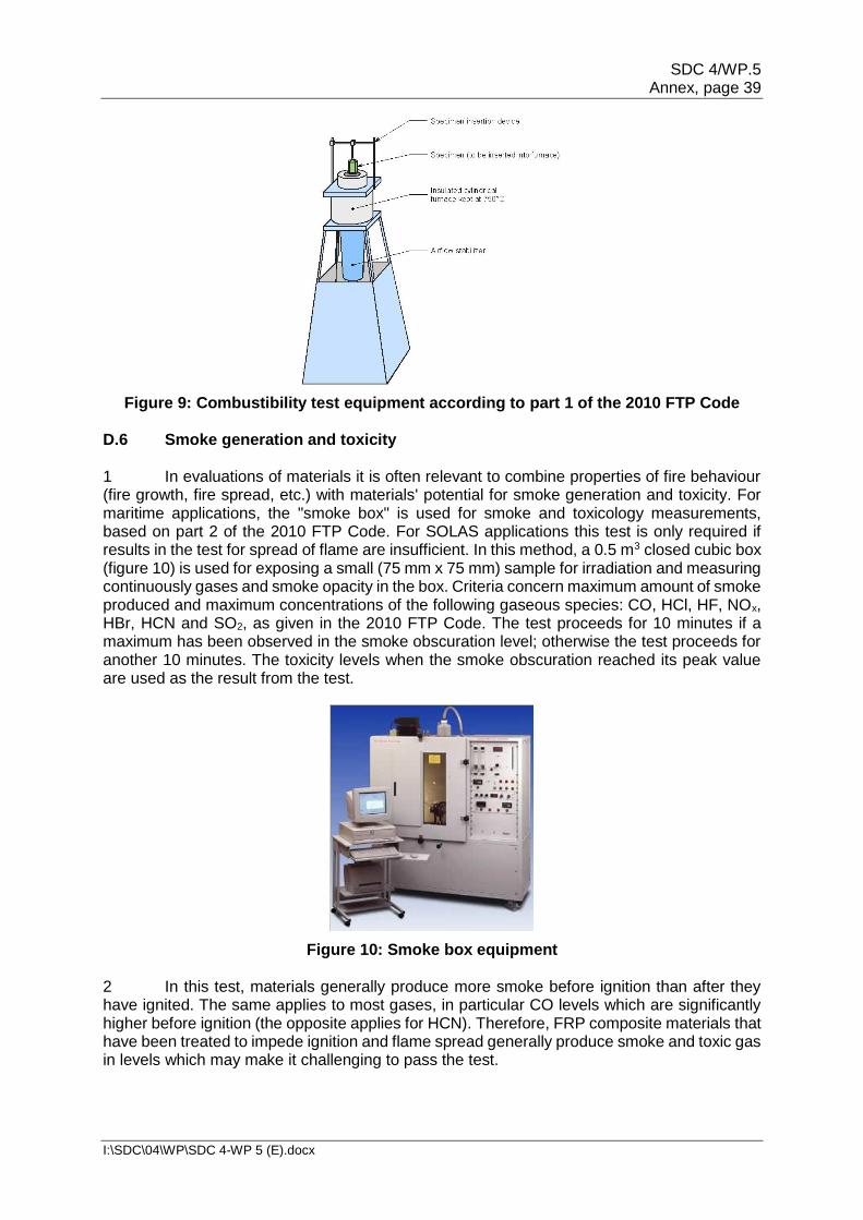
2.1 Laminates, sandwich panels and stiffeners formed by polymers, fibres and core materials may be combined in different ways to make up FRP elements on ships. Within these guidelines, FRP is defined as multi-material compositions of monolithic or sandwich constructions. Monolithic constructions and skin layers of sandwich constructions are based on long-fibre reinforced resins. Reinforcements can be for example fabrics of glass, carbon, aramide or basalt fibres. Resins shall be based on duromer (thermoset) resin. Sandwich core materials are typically based on structural foams or honeycombs. Coatings (gelcoats, topcoats or paints), casting masses and adhesives are handled under these guidelines as well. Some typical FRP composite materials and compositions used in shipbuilding are further described in appendix B (FRP composite materials and compositions used in shipbuilding). It also exemplifies fire behaviour of typical FRP composite constituents and compositions. Relevant fire properties of the particular materials considered in an alternative design must be derived by tests for each specific design case (see appendix D (Fire testing of FRP composite)).
2.2 Use of FRP composites on SOLAS vessels is generally not allowed due to prescriptive requirements on use of non-combustible materials. However, when design or arrangements deviate from the prescriptive requirements of SOLAS chapter II-2, review and approval can be carried out in accordance with SOLAS regulation II-2/17. Combustible FRP elements and related safety measures can thus be treated as alternative fire safety design and arrangements. Engineering analysis, evaluation and approval shall then be carried out based on a procedure summarized in the regulation, whilst more detailed descriptions are contained in the Guidelines on alternative design and arrangements for fire safety (MSC/Circ.1002, as amended by MSC.1/Circ.1552). Life safety performance criteria are contained in MSC.1/Circ.1552. These guidelines support the use of performance-based methods of fire safety engineering to verify that the fire safety of a ship with alternative design and arrangements is equivalent to the fire safety stipulated by prescriptive requirements, a concept often referred to as the "equivalence principle". Briefly, the procedure can be described as a two-step deterministic risk assessment carried out by a design team. The two major parts to be performed are:
.1 the preliminary analysis in qualitative terms; and
.2 the quantitative analysis.
In the first part, the design team is to define the scope of the analysis, identify hazards and, from these, develop design fire scenarios as well as develop trial alternative designs. The different components of the preliminary analysis in qualitative terms are documented in a preliminary analysis report which needs consent by the design team before it is sent to the Administration for review. With the Administration's approval, the preliminary analysis report documents the inputs to the next step of the assessment, the quantitative analysis. At this stage, the design fire scenarios are quantified and outcomes are compared with performance criteria determined based on the fire safety objectives and the functional requirements of the SOLAS regulations. The criteria are quantified with reference to relevant prescriptive requirements or by comparison to the performance of an acceptable prescriptive design. The documented level of fire safety of the alternative design and arrangements may therefore not be absolute but relative to the fire safety of a traditional design, which is a product of the fire safety implied by prescriptive regulations. Accounting for uncertainties when comparing levels of fire safety, the final documentation of the engineering analysis based on SOLAS regulation II-2/17 (hereafter referred to as "SOLAS regulation II-2/17 assessment") should with reasonable confidence demonstrate that the fire safety of the alternative design and arrangements is at least equivalent to that of a prescriptive design.
SDC 4/WP.5 Annex, page 4
I:\SDC\04\WP\SDC 4-WP 5 (E).docx
2.3 According to SOLAS regulation II-2/17, alternative design and arrangements for fire safety should provide a degree of safety at least equivalent to that achieved by compliance with the prescriptive requirements. It is therefore important that the approach used to assess safety can properly describe the effects on fire safety posed by the alternative design and arrangements, i.e. descriptions of uncertainties must be sufficient to establish appropriate safety margins. This is a particularly relevant consideration when evaluating FRP composite structures. Depending on the scope, an assessment in accordance with MSC/Circ.1002, as amended by MSC.1/Circ.1552, could appear overly complex or insufficient. Recommendations and requirements for the method used to assess the safety of an alternative design involving FRP composite structures are discussed in appendix C (Recommendations regarding the assessment). It may also be relevant to consider the Guidelines for the approval of alternatives and equivalents as provided for in various IMO instruments (MSC.1/Circ.1455), which describe an approach which is more adaptable to the scope of the alternative design and arrangements. MSC.1/Circ.1455 was developed to provide a consistent process for the coordination, review and approval of alternative design and arrangements in general, i.e. not only concerning fire safety. It may therefore provide additional guidance when the use of FRP composite structures affects other aspects of safety than those related to fire (see appendix A (Issues other than fire safety)). In detail it also describes the risk-based approval process surrounding the assessment. As referred to in SOLAS, the guidelines in this document take basis in MSC/Circ.1002, as amended by MSC.1/Circ.1552. 2.4 One of the first and most foundational steps in the SOLAS regulation II-2/17 assessment is to form an approval basis. This is done by identifying the prescriptive requirement(s) deviated by the alternative design and arrangements (SOLAS regulation II-2/17.3.2). With an understanding of their associated functional requirements, the deviated prescriptive requirements are then used to define performance criteria, as described in MSC/Circ.1002, as amended by MSC.1/Circ.1552, paragraphs 4.4, 5.1.2 and 6.3.2 and in SOLAS regulation II-2/17.3.4. However, due to limitations in the current regulations, identification of deviated prescriptive requirements may not form a sufficient basis to ensure equivalent safety. When considering FRP composite structures, deviations fundamentally concern the required non-combustibility of structures. With the assumption that non-combustible structures are used, the fire safety regulations include unwritten (implicit) safety requirements. In order to establish an appropriate approval basis, it is therefore required in each design case to perform the necessary investigations to identify all relevant effects on fire safety. This is further described in appendix C (Recommendations regarding the assessment). In particular, the achievement of each fire safety objective and functional requirement should be judged independently, including the functional requirements in purpose statements at the beginning of the regulations. Potential challenges to fire safety objectives, functional requirements, purpose statements and prescriptive requirements in SOLAS chapter II-2 when considering FRP elements are exemplified in chapter 3 (Important factors to consider when evaluating FRP elements with starting point in the regulations of SOLAS chapter II-2). Further recommendations regarding an assessment of fire safety involving FRP elements are presented in appendix C (Recommendations regarding the assessment). 2.5 A number of fire hazards may be introduced by the use of FRP elements. A useful starting point for the hazard identification is the investigation of challenges to regulations and thus chapter 3 (Important factors to consider when evaluating FRP elements with starting point in the regulations of SOLAS chapter II-2). Fire hazards relevant for further investigation, categorized according to the regulations in SOLAS chapter II-2, are particularly:
.1 probability of ignition; .2 fire growth potential;
SDC 4/WP.5 Annex, page 5
I:\SDC\04\WP\SDC 4-WP 5 (E).docx
.3 potential to generate smoke and toxic products; .4 containment of fire; .5 firefighting; and .6 structural integrity.
2.6 The fire hazards and performance of safety measures may be quantified by tools for fire safety engineering and risk assessment and with reference to fire tests (see appendix D (Fire testing of FRP composite)). Sufficient safety may be assured within delimited areas separately, e.g. covered by functional requirements or regulations, or included in a holistic estimation of effects on safety. The former is illustrated along with further examples of an assessment in appendix E (Assessment examples). 2.7 Key terms are defined in MSC/Circ.1002, as amended by MSC.1/Circ.1552, and MSC.1/Circ.1455, as well as in fire safety engineering guidelines for buildings, e.g. ISO 23932. Chapter 3 Important factors to consider when evaluating FRP elements with starting
point in the regulations of SOLAS chapter II-2 The different fire safety regulations in SOLAS chapter II-2 have been analysed with the intention to identify important factors that could be necessary to address when using FRP elements in ship structures. These factors are described in the following paragraphs. Each of the regulations with prescriptive requirements (regulations 4 to 23) starts with a purpose statement. Each purpose statement consists of a regulation objective and one or several regulation functional requirements. The purpose statements have been reproduced for each regulation followed by comments on how a ship with FRP elements may challenge the regulation. The regulations are not only investigated based on potential deviations and how these may have an effect on safety but also in a broader sense, i.e. how a ship with FRP composite structures could affect the regulations' purpose statements or envisioned purpose. Note that this investigation of the regulations is not complete and may not cover all relevant effects on fire safety for a certain design and arrangements with FRP composite structures. The intention is for these guidelines to be developed, concretized and updated based on the regulations. In particular, some of the regulations could be investigated in more detail and from different perspectives. 3.1 Regulation 1 – Application There are currently no comments to this regulation with regard to FRP composite. 3.2 Regulation 2 – Fire safety objectives and functional requirements Paragraph 2 states a number of functional requirements which are embodied in the regulations of the fire safety chapter in order to achieve the fire safety objectives set out in paragraph 1. In particular, the third functional requirement (regulation 2.2.1.3) requires restricted use of combustible material. The fire safety objectives and the functional requirements can be achieved by ensuring compliance with all prescriptive requirements in parts B, C, D, E and G or by alternative design and arrangements which comply with part F (regulation 17). Approval in accordance with regulation 17 still requires that the alternative design and arrangements meet the fire safety objectives and the functional requirements but allows doing so in a different way than in accordance with the prescriptive requirements.
SDC 4/WP.5 Annex, page 6
I:\SDC\04\WP\SDC 4-WP 5 (E).docx
In evaluating the achievement of the fire safety objectives and the functional requirements from a broad perspective, it may be stated that a ship with FRP elements may achieve some better and some worse than a traditional design. The focus on safety of human life in the fire safety objectives makes it topical to address not only the safety of passengers, but also the safety of firefighters and crew. Consideration of the functional requirements especially indicates that risks from adding combustible materials need to be accounted for.
3.3 Regulation 3 – Definitions
From the definitions in this regulation a few details may be useful to recapitulate with regard to FRP composite:
3.2 From the definition of "A" class divisions it should be noted that such divisions are described to be constructed of "steel or other equivalent material" and that they should be so constructed as to be capable to preventing the passage of smoke and flame to the end of the one-hour standard fire test.
3.4 From the definition of "B" class divisions it should be noted that such divisions are described to be constructed of "approved non-combustible materials" and that they should be so constructed as to be capable to preventing the passage of smoke and flame to the end of the first half hour of the standard fire test.
3.10 From the definition of "C" class divisions it should be noted that such divisions are described to be constructed of "approved non-combustible materials" and that no other requirements apply.
3.33 From the definition of non-combustible material it should be noted that such material is described to neither burn nor to give off flammable vapours in sufficient quantity for self-ignition when heated to approximately 750°C.
3.43 From the definition of steel or other equivalent material it should be noted that the phrase refers to any non-combustible material which, by itself or due to insulation provided, has structural and integrity properties equivalent to steel at the end of the applicable exposure to the standard fire test. Therefore, there are requirements regarding non-combustibility as well as structural and integrity properties. Note that the former is not limited in time but the latter requirements need only be achieved until the end of the applicable exposure of the standard fire test. An aluminium alloy with appropriate insulation is used to exemplify an equivalent material to steel.
3.47 From the definition of a standard fire test it is described to be a test in which specimens of the relevant bulkheads or decks are exposed in a test furnace to temperatures corresponding approximately to the standard time-temperature curve.
3.4 Regulation 4 – Probability of ignition
Purpose statement:
The purpose of this regulation is to prevent the ignition of combustible materials or flammable liquids. For this purpose, the following functional requirements shall be met:
.1 means shall be provided to control leaks of flammable liquids;
.2 means shall be provided to limit accumulation of flammable vapours;
.3 the ignitability of combustible materials shall be restricted;
SDC 4/WP.5 Annex, page 7
I:\SDC\04\WP\SDC 4-WP 5 (E).docx
.4 ignition sources shall be restricted; .5 ignition sources shall be separated from combustible materials and
flammable liquids; and .6 the atmosphere in cargo tanks shall be maintained out of the explosive
range. Comments: 1 Using combustible materials for structures is not in conflict with the objective of this regulation. However, it states to aim at preventing the ignition of combustible materials. Looking at the prescriptive requirements, they prevent the occurrence of fire by restricting ignition sources and some combustibles. Mainly fuels and the handling of highly flammable substances are concerned, but also a few miscellaneous items in enclosures. Most are ignition sources and the only actual combustible material concerned is primary deck coverings. If applied within accommodation, service or control spaces or on cabin balconies, they shall not readily ignite (regulation 4.4.4). This requirement may seem a bit illogical since a primary deck covering is the first layer fitted on a deck, used to smooth out unevenness, and covered by a floor construction. It is rather the surface of the floor construction which may be exposed to a potential ignition source. Furthermore, the requirement implies the primary deck coverings should have low flame-spread characteristics, which is a requirement that fits better in regulation 5. However, apart from this requirement, there are no other prescriptive requirements to be found on how the ignitability of combustible materials shall be restricted, as stated amongst the functional requirements in the purpose statement. 2 New hazards may be introduced where FRP composite is used close to significant ignition sources, such as exhaust pipes or other high-temperature surfaces. It may be argued that this challenges the functional requirement on separation of ignition sources from combustible materials. Due to assumptions regarding the use of non-combustible structures, this safety function is not clearly stated in prescriptive requirements of this regulation. It is nevertheless important to identify ignition sources and ensure that FRP composite surfaces are properly protected. 3 It may be argued that leaving combustible FRP composite surfaces unprotected is not in line with the functional requirement concerning restricted combustibility. However, this rather concerns ignition sources and easily ignitable (e.g. by a small flame) combustibles and flammable substances whilst combustible materials which have restricted ignitability, such as FRP composite, are managed in regulation 5. It is noted that an IMO test method for evaluation of restricted ignitability of products does not exist. 3.5 Regulation 5 – Fire growth potential Purpose statement: The purpose of this regulation is to limit the fire growth potential in every space of
the ship. For this purpose, the following functional requirements shall be met: .1 means of control for the air supply to the space shall be provided; .2 means of control for flammable liquids in the space shall be provided; and
.3 the use of combustible materials shall be restricted.
SDC 4/WP.5 Annex, page 8
I:\SDC\04\WP\SDC 4-WP 5 (E).docx
Comments:
1 This regulation oversees materials and other items in spaces with the intention to limit the fire growth potential. Looking at the functional requirements, neither of the first two is affected by use of FRP elements in ship constructions. However, the third functional requirement must be taken into account as it states that the use of combustible materials shall be restricted. The definition of a non-combustible material is given in regulation 3.33 and defines it as a material that neither burns nor gives off flammable vapours when heated to 750°C. For example, vinyl ester, which is often used as resin in FRP composite, will give rise to pyrolysis gases above 500°C.
2 In the prescriptive requirements, use of non-combustible and combustible materials is primarily managed in paragraph 3. Except interiors and furnishings, the requirements concern linings, grounds, draught stops, ceilings, faces, mouldings, decorations, veneers, insulation materials, partial bulkheads etc. These are also the materials that will govern the growth phase of a fire, together with, for example, luggage and other loose fittings. In general, all surfaces and linings in accommodation and service spaces must fulfil requirements of a maximum calorific value of 45 MJ/m2, a maximum volume of combustible material and have low flame-spread characteristics according to the FTP Code. However, since the regulations assume that the bulkhead plate behind any wall construction is steel, there are no requirements regarding the materials behind the wall construction.
3 The requirements in this regulation could be claimed to apply to surfaces of any sort. Therefore, if the same approved materials for linings, grounds, draught stops, ceilings, faces, mouldings, decorations, veneers, etc. are used in a ship with FRP composite constructions as in a traditional (prescriptive) design, it could be claimed that the design complies with the prescriptive requirements in regulation 5. This would generally not increase the fire growth potential in the spaces in the initial stages during evacuation. However, if the FRP composite surfaces are left uncovered or if divisions are constructed with combustible FRP composite just underneath surfaces of low flame-spread characteristics, it can be argued that the surface laminate in fact represents the surface lining, to which requirements regarding low flame-spread characteristics and maximum volume of combustible material apply; the requirement on maximum calorific value would then apply to the core. With this reasoning all of these requirements would generally be deviated.
4 As mentioned above, thermal insulation may be used to provide structural integrity, which will also protect the combustible FRP composite surfaces from fire involvement, e.g. for 60 minutes. In this case the FRP composite will not add to the fire growth potential in the space within the first hour of a fire having the same intensity as a standard fire test curve.
5 As mentioned above, this regulation covers materials and other items in spaces with the intention to limit the fire growth potential. All discussions above have considered internal spaces. Since external surfaces on ships are typically made up of painted steel there has not been any reason to regulate this matter. This is another example of where the FRP composite goes beyond the steel-based regulations. Making exterior surfaces in combustible FRP composite will affect the fire growth potential and could cause vertical fire spread between decks, which is a hazard that must be addressed on these ships. Hazardous exterior surfaces could for example be protected to achieve low flame-spread characteristics or be protected with drencher system. An indirect way to manage the problem is to use fire rated windows, which could avoid fire spread.
SDC 4/WP.5 Annex, page 9
I:\SDC\04\WP\SDC 4-WP 5 (E).docx
3.6 Regulation 6 – Smoke generation potential and toxicity Purpose statement: The purpose of this regulation is to reduce the hazard to life from smoke and toxic
products generated during a fire in spaces where persons normally work or live. For this purpose, the quantity of smoke and toxic products released from combustible materials, including surface finishes, during fire shall be limited.
Comments: 1 Similarly to regulation 5, the prescriptive requirements of regulation 6 mostly concern enclosures. All materials involved in a fire will contribute to the production of toxic smoke but during the first stages of a fire it is mainly the exposed surface that will contribute to the generation and toxicity of smoke. This regulation generally controls exposed surface finishes and primary deck coverings. 2 FRP composites could either be covered with approved surface materials or left unprotected. In spaces where the FRP composite is left unprotected, it could be difficult to fulfil regulation 6.2.1. Furthermore, if an approved surface material is used on the FRP composite, it may be argued that the regulations are predicated on that a non-combustible material is used for the ship structures that are underneath. The generation and toxicity of smoke may, depending on the construction, therefore not be limited to the same extent as in a prescriptive design during an enclosure fire. 3 When scrutinizing regulations 5 and 6, it is important to realize that both regulations manage smoke production but where the latter mainly has to do with the individual material characteristics, it could be said that regulation 5 manages so that an unlimited area of combustible materials does not catch fire and produce smoke and that regulation 6 manages the potential of each square meter that can be involved in a fire. 4 Thermal insulation may be used to protect the combustible FRP composite surfaces from becoming involved in a fire. For the time that the construction is thermally protected, the FRP composite will not add to the generation or toxicity of the produced smoke. In the event of a fire lasting long enough to involve the FRP composite divisions, an increased generation and toxicity of smoke could be argued to occur, in comparison with a steel ship. This will depend on the selection of plastic materials. For instance, PVC is known to release highly toxic hydrochloric acid (HCl) during combustion. 5 It is hard to predict whether the smoke generation and toxicity at a given time would be worse in a ship with FRP elements compared to a steel ship depending on the insulating capacity of the construction. If thermal insulation is used to protect the FRP composite, fire spread will likely be delayed. It could be noted that when a fire starts to involve the protected FRP composite divisions, conditions will already have been uninhabitable for a while. An increased smoke generation or toxicity could be hazardous to persons on the embarkation deck depending on wind direction. 6 Fires on open deck and involving exterior surfaces in FRP composite could also be affected by the smoke generation and toxicity. However, this problem may not be as relevant when considering exteriors, since smoke management is not critical.
SDC 4/WP.5 Annex, page 10
I:\SDC\04\WP\SDC 4-WP 5 (E).docx
3.7 Regulation 7 – Detection and alarm Purpose statement:
The purpose of this regulation is to detect a fire in the space of origin and to provide for alarm for safe escape and firefighting activity. For this purpose, the following functional requirements shall be met:
.1 fixed fire detection and fire alarm system installations shall be suitable for the
nature of the space, fire growth potential and potential generation of smoke and gases;
.2 manually operated call points shall be placed effectively to ensure a readily
accessible means of notification; and .3 fire patrols shall provide an effective means of detecting and locating fires
and alerting the navigation bridge and fire teams. Comments: In general, use of FRP composite does not present any deviations from prescriptive requirements. However, the functional requirements give reason to oversee the need for detection. Considering the first regulation functional requirement, there is no reason to believe that significantly less smoke is produced by FRP composites than organic materials in general. However, since the fire growth potential in some areas may be affected, there may also be an additional need for detection. For areas where non-insulated FRP elements are used, it is particularly critical to provide early activation of an extinguishing system with quick detection. It may therefore be relevant with faster or more reliable smoke detection or to provide it in additional areas of the ship, possibly even in open spaces or void spaces. The potential increased need for detection should be considered in the fire risk assessment and depends on how FRP composite is used. 3.8 Regulation 8 – Control of smoke spread Purpose statement: The purpose of this regulation is to control the spread of smoke in order to minimize
the hazard from smoke. For this purpose, means for controlling smoke in atriums, control stations, machinery spaces and concealed spaces shall be provided.
Comments: As discussed in 3.6 (regulation 6 – Smoke generation potential and toxicity) the amount of smoke generated in a fire test with FRP composite structures (glass fibre reinforced polyester with PVC core) was only slightly larger than that from a fire in a steel ship. If this is the case for the alternative design and arrangements being evaluated, this would indicate that the current requirements for control of smoke spread could be met. 3.9 Regulation 9 – Containment of fire Purpose statement:
The purpose of this regulation is to contain the fire in the space of origin. For this purpose the following requirements shall be met:
SDC 4/WP.5 Annex, page 11
I:\SDC\04\WP\SDC 4-WP 5 (E).docx
.1 the ship shall be divided by thermal and structural boundaries; .2 thermal insulation boundaries shall have due regard to the fire risk of the space
and adjacent spaces; and .3 the fire integrity of the division shall be maintained at openings and
penetrations. Comments: 1 This regulation prescribes main vertical and horizontal zones and, where necessary, internal bulkheads to be made up by divisions of "A" class standard. "A" class means that steel or other equivalent material shall be used. Regulation 3.43 defines steel or other equivalent material as a non-combustible material which, by itself or by insulation provided, has structural and integrity properties equivalent to those of steel at the end of the standard fire test. Unprotected FRP composite generally ignites when exposed to significant fire but could for example be combined with thermal insulation in order to gain fire integrity comparable with "A" class standard. Tests have demonstrated that the temperature rise at the unexposed side of a FRD60 (cf. HSC Code) division will be as low as 45°C after 60 minutes of fire exposure (temperature rise and integrity test in accordance with the standard test for bulkheads and decks, see the Test procedures for fire-resisting divisions of high-speed craft (MSC 45(65)). This low conduction of heat will prevent heat from being transferred long distances through the ship structure, which may be a fire risk in conventional ships. 2 The low conductivity of a FRD60 division can also give rise to a faster fire development within the enclosed space, equivalent to an insulated aluminium structure or a heavily insulated steel structure (e.g. "A-60" class). When insulation or any protective surface layer is deteriorated and the surface temperature of the FRP composite reaches its ignition temperature, the FRP composite will start contributing to the fire, which could also accelerate the fire development if additional oxygen is available. 3 Specific fire integrity and insulation requirements for internal decks and bulkheads depend on a classification made of the spaces and are given in tables in regulation 9. The way spaces are assigned fire categories may need to be reconsidered, in particular for spaces with added fire load by exposed untreated FRP composite. This includes open decks. 4 If FRP composite is used on open deck, all connections between interior and external spaces must be reconsidered. Design of windows, doors and ventilation systems may, for example, need to be reconsidered due to the potential external fire hazards, i.e. due to potential spread of smoke and fire into the ship or out to external surfaces.
5 Regarding penetrations in fire-resisting divisions, doors, pipes, window frames etc. are generally also required to be non-combustible when penetrating "A" class divisions. The integration of such penetrations into an FRP composite division must be documented by fire tests or potentially by engineering judgement. The integration of doors, windows, cable glands, ducts, fire dampers and pipes in FRP composite fire divisions has been successfully demonstrated in tests. 6 A robust integration of the insulation systems onto an FRP composite fire division is crucial. The effect of voids between insulation and the composite structure could be further evaluated. Essential systems in a fire situation, such as sprinkler systems, piping, ducts, etc., must have a fastening/support system that is designed not to fail in case of a fire.
SDC 4/WP.5 Annex, page 12
I:\SDC\04\WP\SDC 4-WP 5 (E).docx
3.10 Regulation 10 – Firefighting Purpose statement: The purpose of this regulation is to suppress and swiftly extinguish fire in the space
of origin. For this purpose the following requirements shall be met:
.1 fixed fire-extinguishing systems shall be installed, having due regard to the fire growth potential of the spaces; and
.2 fire-extinguishing appliances shall be readily available.
Comments: 1 The first functional requirement states that the fixed fire-extinguishing systems shall have due regard to the fire growth potential of the space. It is only if the fire growth potential differs significantly that it is necessary to take into account FRP composites when designing the fire-extinguishing systems. In most cases, fire growth in the FRP composite will not be dimensioning for the fire-extinguishing system since more rapid fire developments can generally occur in other combustibles and since the size of a fire depends on the oxygen supply. The fire pump capacity and pressure requirements should therefore generally not need to be changed. However, since early extinguishment is important, it may still be suitable to oversee the firefighting systems and that extinguishment is managed properly. 2 It may also be necessary to consider fire-extinguishing systems and equipment in additional places of a ship with FRP composite constructions. If exterior surfaces are made of FRP composite they may need to be protected in order to prevent an enclosure fire from spreading to the exteriors if a door or window is left open or broken, e.g. by a sprinkler above the openings. It may also be relevant to install drencher systems covering essential parts of the hull or exteriors of superstructure, if there is a risk of fire spread or deterioration of structural performance. 3 Even though the purpose statements and prescriptive requirements of this regulation only cover fire-extinguishing systems and appliances, it is in the context of the regulation title also relevant to consider effects on manual firefighting routines. There are a few significant differences:
.1 First and foremost, the need to perform defensive boundary cooling from the outside of a fire enclosure is removed. It is instead important to have an offensive strategy to provide direct cooling of the fire. Boundary cooling is a strategy that requires many resources without actually fighting the fire, but mainly hindering fire spread. A much more efficient way to fight a fire is to quickly reach inside the enclosure. With traditional equipment this may not be possible due to the heat or risk of fire spread if a door is opened. However, there is more suitable firefighting equipment already in use, such as the Cutting Extinguisher or Fog Spear. Tests have demonstrated that firefighting by such equipment through small holes in the FRP composite boundaries is very effective. The holes may be pre-fabricated or made by equipment on site. This will allow dampening the fire from outside of the fire origin. Suitable equipment in combination with a rerouting of firefighting resources relieved from boundary cooling to either assist in active combat of the fire may increase both effectiveness and efficiency.
SDC 4/WP.5 Annex, page 13
I:\SDC\04\WP\SDC 4-WP 5 (E).docx
.2 Furthermore, a fire which has taken root in the FRP composite may be difficult to fully extinguish. This implies more resources will be needed to keep watch over fire-scorched areas to ensure that the FRP composite does not reignite. This may not significantly interfere with the critical stages of taking control of the fire.
.3 Another aspect of how firefighting routines could be affected is that the improved thermal resistance of FRP composite structures could imply difficulties in finding the seat of the fire from adjacent compartments with a commonly used thermal imaging camera.
.4 Routines regarding potential collapse must also be developed in order to insure the safety of passengers and firefighting crew.
4 All in all, the ability to focus more resources on actively fighting the fire, combined with the introduction of tools to cool hot fire gases from an adjacent compartment could improve the efficiency and effectiveness of firefighting in ships with FRP composite structures. In any case, effects on firefighting routines must be taken into consideration when making ship structures in FRP composite.
5 Additional equipment for manual firefighting could also be necessary, e.g. in open deck spaces surrounded by FRP composite surfaces.
3.11 Regulation 11 – Structural integrity
Purpose statement:
The purpose of this regulation is to maintain structural integrity of the ship, preventing partial or whole collapse of the ship structures due to strength deterioration by heat. For this purpose, the materials used in the ships' structure shall ensure that the structural integrity is not degraded due to fire.
Comments:
1 This regulation intends to ensure that structural integrity is maintained in case of a fire. After the purpose statement of the regulation, paragraph 2 of regulation 11 states that:
"The hull, superstructures, structural bulkheads, decks and deckhouses shall be constructed of steel or other equivalent material. For the purpose of applying the definition of steel or other equivalent material as given in regulation 3.43, the "applicable fire exposure" shall be according to the integrity and insulation standards given in tables 9.1 to 9.4. For example, where divisions such as decks or sides and ends of deckhouses are permitted to have "B-0" fire integrity, the "applicable fire exposure" shall be half an hour."
2 Structures shall thus be constructed of steel or other equivalent material, i.e. any non-combustible material which, by itself or due to insulation provided, has structural and integrity properties equivalent to steel at the end of the standard fire test. This prescriptive requirement cannot be complied with if combustible FRP composite structures are used. The existing fire tests within the FTP Code for A and B class divisions are conducted over a period of up to 60 minutes. Structural and integrity properties equivalent to steel may be achieved for such a time of fire exposure in the standardized test, for example if the FRP composite is sufficiently insulated. However, unlike the requirements on structural and integrity properties, the requirement on non-combustibility is not time-limited. The fire tests do not assess the performance of the material after the end of the test, nor when subject to load.
SDC 4/WP.5 Annex, page 14
I:\SDC\04\WP\SDC 4-WP 5 (E).docx
3 Insulated steel divisions may lose fire integrity after for example 60 min; not due to strength deterioration by heat but due to possible fire spread to adjacent compartments by heat transfer. A prolonged fire could involve and deteriorate an FRP composite structure when thermal insulation or other means are no longer enough to provide structural and integrity performance. A large enough fire could then bring about a local collapse.
4 Steel generally loses its structural strength at about 400°C to 600°C and an unstiffened FRP composite sandwich panel may lose bonding between core and laminate, and thereby structural performance, when heated to about 150°C (or a temperature where the bonding between core and laminate starts to soften). Improved structural integrity of FRP composite structures may be achieved by use of e.g. stiffeners, pillars or additional layers but steel ships have proved to be able to survive fire for several days without progressive structural collapse occurring. This is particularly important when considering that the ship shall retain safe areas for the refuge of passengers (SOLAS regulation II-2/21.5), including control stations to remain intact and habitable for command and control activities necessary during an incident. This can for example affect the measures required to achieve successful evacuation of the ship (cf. HSC Code). It is crucial that fire hazards introduced in case of a long-lasting fire (lasting for more than 60 minutes) are addressed in the SOLAS regulation II-2/17 assessment.
5 Deviations from prescriptive requirements are found in regulation 11.4 if steel (not "steel or other equivalent material") is not used for structures forming crowns, casings and floor plating of machinery spaces of category A. Use of FRP composite for such structures may need special consideration.
6 Further to the above, steel-FRP joints need to be assessed in detail to ensure that structural fire integrity is achieved (see also section B.3.4 of appendix B).
3.12 Regulation 12 – Notification of crew and passengers
Purpose statement:
The purpose of this regulation is to notify crew and passengers of a fire for safe evacuation. For this purpose, a general emergency alarm system and a public address system shall be provided.
Comments:
There are no obvious challenges posed to this regulation by the use of FRP composite. However, a public address system may be indirectly affected if special instructions must be made to avoid passengers to reside in certain areas where there is a risk of collapse. An exterior fire could also affect the possibility of using certain exterior areas or life-saving appliances.
3.13 Regulation 13 – Means of escape
Purpose statement:
The purpose of this regulation is to provide means of escape so that persons on board can safely and swiftly escape to the lifeboat and liferaft embarkation deck. For this purpose, the following functional requirements shall be met:
.1 safe escape routes shall be provided;
.2 escape routes shall be maintained in a safe condition, clear of obstacles; and
SDC 4/WP.5 Annex, page 15
I:\SDC\04\WP\SDC 4-WP 5 (E).docx
.3 additional aids for escape shall be provided as necessary to ensure accessibility, clear marking, and adequate design for emergency situations.
Comments: 1 This regulation aims to provide means for persons to safely and swiftly escape a fire, assemble and proceed to their embarkation station. Considering the prescriptive requirements, regulation 13.3.1.3 requires all stairways in accommodation spaces, service spaces and control stations to be of steel frame construction or other equivalent material sanctioned by the Administration. If they are made of FRP composites they need to be evaluated in the fire safety analysis. The same applies to stairways and ladders in machinery spaces (regulation 13.4.1). However, such constructions are generally not considered in other materials than steel, even on ships in FRP composite. It may be noted that safe havens and escape ways manufactured from composites are used in the offshore industry. 2 In order to achieve safe escape routes, regulation 13 requires fire integrity and insulation in several places, referring to values in regulation 9 (tables 9.1 to 9.4). A sufficiently insulated FRP composite division could be claimed to achieve these requirements (since non-combustibility is not required). 3 In an FRP composite structure the temperature on the unexposed side could, due to the high insulation capacity of the composite construction, be very low even after 60 minutes of fire. The heat from a fire will therefore to a larger extent stay in the fire enclosure and not easily be transmitted to adjacent spaces. This could be advantageous in an escape situation. 3.14 Regulation 14 – Operational readiness and maintenance Purpose statement:
The purpose of this regulation is to maintain and monitor the effectiveness of the fire safety measures the ship is provided with. For this purpose the following functional requirements shall be met:
.1 fire protection systems and firefighting systems and appliances shall be
maintained ready for use; and .2 fire protection systems and firefighting systems and appliances shall be
properly tested and inspected. Comments: The functional requirements are not affected by use of FRP composite. The fire protection systems and firefighting systems and appliances must be maintained ready for use and should be properly tested and inspected on a ship with FRP composite structures, as on any ship. Even if the regulation may be directly applied and no deviations are posed, the content covered by this regulation may be affected. Depending on the alternative design and arrangements, there may be a need for faster extinguishment, increased capacity or improved reliability and consequently more maintenance.
SDC 4/WP.5 Annex, page 16
I:\SDC\04\WP\SDC 4-WP 5 (E).docx
3.15 Regulation 15 – Instructions, onboard training and drills Purpose statement:
The purpose of this regulation is to mitigate the consequences of fire by means of proper instructions for training and drills of persons on board in correct procedures under emergency conditions. For this purpose, the crew shall have the necessary knowledge and skills to handle fire emergency cases, including passenger care.
Comments: Except for the need for increased knowledge of firefighters considering strategies, techniques, routines, etc. (see 4.10), there are no direct differences on a ship with FRP composite structures in comparison with a traditionally built ship. In similarity with regulation 14, the content covered by this regulation may be affected depending on the systems considered in the alternative design and arrangements. 3.16 Regulation 16 – Operations Purpose statement:
The purpose of this regulation is to provide information and instructions for proper ship and cargo handling operations in relation to fire safety. For this purpose, the following functional requirements shall be met:
.1 fire safety operational booklets shall be provided on board; and .2 flammable vapour releases from cargo tank venting shall be controlled.
Comments: There are no known challenges posed to this regulation for a ship with FRP composite structures. In similarity with regulation 14, the content covered by this regulation may nevertheless be affected depending on the solutions considered in the alternative design and arrangements. 3.17 Regulation 17 – Alternative design and arrangements Purpose statement:
The purpose of this regulation is to provide a methodology for alternative design and arrangements for fire safety.
Comments: The method described in regulation 17 (and MSC/Circ.1002, as amended by MSC.1/Circ.1552) and its suitability when assessing fire safety in FRP composite constructions is discussed in chapter 6 of these guidelines.
The purpose of this regulation is to provide additional measures in order to address the fire safety objectives of this chapter for ships fitted with special facilities for helicopters. For this purpose, the following functional requirements shall be met:
.1 helideck structure shall be adequate to protect the ship from the fire hazards
associated with helicopter operations; .2 firefighting appliances shall be provided to adequately protect the ship from
the fire hazards associated with helicopter operations; .3 refuelling and hangar facilities and operations shall provide the necessary
measures to protect the ship from the fire hazards associated with helicopter operations; and
.4 operation manuals and training shall be provided.
Comments: Helicopter decks have previously been built with FRP composite materials on non-SOLAS ships but will require special evaluations, including testing, and tailored detection and extinguishment. 3.19 Regulation 19 – Carriage of dangerous goods Purpose statement:
The purpose of this regulation is to provide additional safety measures in order to address the fire safety objectives of this chapter for ships carrying dangerous goods. For this purpose, the following functional requirements shall be met: .1 fire protection systems shall be provided to protect the ship from the added
fire hazards associated with carriage of dangerous goods; .2 dangerous goods shall be adequately separated from ignition sources; and .3 appropriate personnel protective equipment shall be provided for the hazards
associated with the carriage of dangerous goods. Comments: None of the prescriptive requirements are likely to be affected by use of FRP composite constructions. However, there may be reason to evaluate potential hazards from leakage of dangerous goods onto an FRP composite deck, not only from a fire perspective. Certain dangerous goods may for example cause the FRP composite to deteriorate if they come in contact. These and other hazardous non-fire related scenarios must be considered. With regard to fire, the time to collapse may change due to a potentially larger fire involving combustible surrounding exterior FRP composite surfaces.
SDC 4/WP.5 Annex, page 18
I:\SDC\04\WP\SDC 4-WP 5 (E).docx
3.20 Regulation 20 – Protection of vehicle, special category and ro-ro spaces Purpose statement:
The purpose of this regulation is to provide additional safety measures in order to address the fire safety objectives of this chapter for ships fitted with vehicle, special category and ro-ro spaces. For this purpose, the following functional requirements shall be met:
.1 fire protection systems shall be provided to adequately protect the ship from
the fire hazards associated with vehicle, special category and ro-ro spaces; .2 ignition sources shall be separated from vehicle, special category and ro-ro
spaces; and .3 vehicle, special category and ro-ro spaces shall be adequately ventilated.
Comments: This regulation describes requirements for ventilation, alarm and detection systems, fire-extinguishing equipment and structural requirements for spaces with vehicles. In passenger ships carrying more than 36 passengers, the boundary bulkheads or decks of the ro-ro space are by regulation 20.5 required to achieve A-60 (with some exceptions where the structural fire protection can be reduced to A-0). This cannot be achieved if such divisions are made of FRP composite. Furthermore, even if not required by prescriptive requirements, it may prove necessary to better address the first regulation functional requirement by passive or active measures, e.g. by an additional active fire-extinguishing system on exterior surfaces. For ro-ro spaces which are not of special category, the fire safety requirements are different and in generally considered less stringent. 3.21 Regulation 21 – Casualty threshold, safe return to port and safe areas Purpose statement:
The purpose of this regulation is to establish design criteria for a ship's safe return to port under its own propulsion after casualty that does not exceed the casualty threshold stipulated in paragraph 3 and also provides functional requirements and performance standards for safe areas.
Comments: Passenger ships constructed on or after 1 July 2010 having a length of 120 m or above or having three or more main vertical zones, shall comply with this regulation. However, FRP composite may be used in superstructures of the ship. In any case, it may be relevant to evaluate e.g. whether the definition of the casualty threshold in regulation 21.3 is appropriate for ships in FRP composite. Furthermore, structural integrity is important to consider (see section 3.11) when considering safe areas for the refuge of passengers (regulation 21.5), including control stations to remain intact and habitable for command and control activities necessary during an incident.
SDC 4/WP.5 Annex, page 19
I:\SDC\04\WP\SDC 4-WP 5 (E).docx
3.22 Regulation 22 – Design criteria for systems to remain operational after a fire casualty
Purpose statement:
The purpose of this regulation is to provide design criteria for systems required to remain operational for supporting the orderly evacuation and abandonment of a ship, if the casualty threshold, as defined in regulation 21.3, is exceeded.
Comments:
Passenger ships constructed on or after 1 July 2010 having a length of 120 m or above or having three or more main vertical zones, shall comply with this regulation. However, FRP composite may be used in superstructures of the ship. In any case, it may be relevant to evaluate e.g. whether there are additional hazards from the potential fire size and potential smoke production from FRP structures with regard to evacuation and abandonment.
3.23 Regulation 23 – Safety centre on passenger ships
Purpose statement:
The purpose of this regulation is to provide a space to assist with the management of emergency situations.
Comments:
Passenger ships constructed on or after 1 July 2010 shall have a safety centre on board complying with the requirements of this regulation. From the safety centre all fire safety systems should be available, such as ventilation systems, alarm systems, fire detection and alarm systems, fire and emergency pumps etc. In general, this is not affected by the FRP composite construction material, but it may be necessary to consider collapse when determining the location of the safety centre.
SDC 4/WP.5 Annex, page 20
I:\SDC\04\WP\SDC 4-WP 5 (E).docx
APPENDIX A
ISSUES OTHER THAN FIRE SAFETY 1 Use of FRP composite may affect other parts of a ship's safety than those associated with fire. Potential issues are listed below, categorized as issues which are indirectly related to fire safety and issues which are unrelated to fire safety. It should be noted that the list of issues in this appendix is not exhaustive and is meant to be used as an example. 2 An example of an issue indirectly related to fire safety is:
If, for example, additional drencher systems are installed in combination with FRP composite, drainage and pumping arrangements may need to be installed in the same manner as in SOLAS regulations II-2/19 and II-2/20.
3 Issues unrelated to fire safety are:
.1 Water intrusion over time in FRP elements:
Experience with FRP has demonstrated that resin-fibre construction may absorb water over the years. This moisture is believed to be the source of free water found in otherwise sound voids.
.2 Required use of steel or other equivalent material in the International
Convention on Load Lines 1966 (1966 LL Convention), which states:
i) Regulation 12: All access doors in bulkheads at ends of enclosed superstructures shall be fitted with doors of steel or other equivalent material.
ii) Regulation 15: Pontoon hatch covers: Gives criterion for deflection
(z-direction) due to uniformly distributed load on pontoon hatch covers. The formula (criterion) is assuming steel as material in the hatches.
iii) Regulation 16: Hatchways closed by weather tight covers of steel or
other equivalent materials: gives criterion for deflection (z-direction) due to uniformly distributed load on pontoon hatch covers. The formula (criterion) is assuming steel as material in the hatches. In addition, hatch covers as per regulation 16 shall be made of steel or other equivalent materials.
iv) Regulation 19: Ventilators "shall be made of steel or other
equivalent materials". v) Regulation 20: Air pipes "exposed parts of air pipes shall be of
substantial construction". These issues could be managed through the opening for performance-based design provided in regulation 2.4 of the 1966 LL Convention, which states "Ships of wood or of composite construction, or of other materials the use of which the Administration has approved, or ships whose construction features are such as to render the application of this annex unreasonable or
SDC 4/WP.5 Annex, page 21
I:\SDC\04\WP\SDC 4-WP 5 (E).docx
impracticable, shall be assigned freeboards as determined by the Administration."
.3 Electromagnetic compatibility (EMC)
In a ship made of steel the hull acts as a counterpoise to external and internal electrical and radio interferences, e.g. lightning or EMC. In an FRP structure the same grounding mechanism is not present, which could interfere and cause problems for the radio communication, radar, fire detection system, automation, etc. Special consideration is needed for addressing compliance with standards such as IEC-60533, stating for example that "complex electric and/or electronic systems require EMC planning in all phases of design and installation, considering the electromagnetic environment, any special requirements and the equipment performance."
.4 Radio communications. .5 Radar issues might need reconsideration. For instance the radar might need
adjustments and should be set up for sector transmission, due to radio wave transparency of the structure and radio frequency hazards.
.6 Electrical issues need to be reconsidered, for instance:
.1 grounding points (FRP structure being non-conductive), i.e reconsider
grounding of the equipment installed on board; .2 insulation measurements; and .3 lightning arrestors.
.7 Damage stability with regard to grounding and collision, floatability, structural integrity and impact strength:
.1 deformation due to unexpected high sea loads (same resistance to
lateral pressure as implied by minimum thickness requirements may conservatively be provided); and
.2 deformations or other damage due to local contacts (same
resistance to lateral pressure as implied by minimum thickness requirements may conservatively be provided).
Experience with the operation of HSLC of composite construction has demonstrated that, when minimum scantling requirements are complied with, no particular problems concerning robustness to local loads have been experienced.
.8 CO2 emissions and fuel efficiency.
.9 Life-saving arrangements.
SDC 4/WP.5 Annex, page 22
I:\SDC\04\WP\SDC 4-WP 5 (E).docx
APPENDIX B
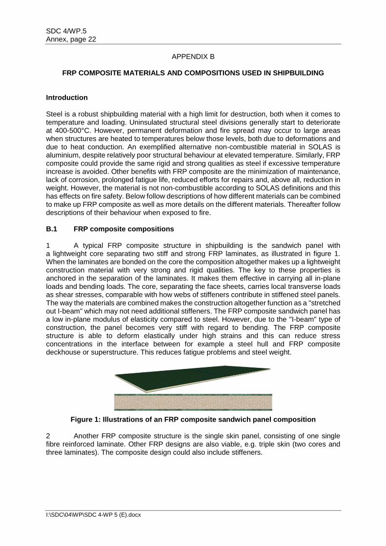
FRP COMPOSITE MATERIALS AND COMPOSITIONS USED IN SHIPBUILDING Introduction Steel is a robust shipbuilding material with a high limit for destruction, both when it comes to temperature and loading. Uninsulated structural steel divisions generally start to deteriorate at 400-500°C. However, permanent deformation and fire spread may occur to large areas when structures are heated to temperatures below those levels, both due to deformations and due to heat conduction. An exemplified alternative non-combustible material in SOLAS is aluminium, despite relatively poor structural behaviour at elevated temperature. Similarly, FRP composite could provide the same rigid and strong qualities as steel if excessive temperature increase is avoided. Other benefits with FRP composite are the minimization of maintenance, lack of corrosion, prolonged fatigue life, reduced efforts for repairs and, above all, reduction in weight. However, the material is not non-combustible according to SOLAS definitions and this has effects on fire safety. Below follow descriptions of how different materials can be combined to make up FRP composite as well as more details on the different materials. Thereafter follow descriptions of their behaviour when exposed to fire. B.1 FRP composite compositions 1 A typical FRP composite structure in shipbuilding is the sandwich panel with a lightweight core separating two stiff and strong FRP laminates, as illustrated in figure 1. When the laminates are bonded on the core the composition altogether makes up a lightweight construction material with very strong and rigid qualities. The key to these properties is anchored in the separation of the laminates. It makes them effective in carrying all in-plane loads and bending loads. The core, separating the face sheets, carries local transverse loads as shear stresses, comparable with how webs of stiffeners contribute in stiffened steel panels. The way the materials are combined makes the construction altogether function as a "stretched out I-beam" which may not need additional stiffeners. The FRP composite sandwich panel has a low in-plane modulus of elasticity compared to steel. However, due to the "I-beam" type of construction, the panel becomes very stiff with regard to bending. The FRP composite structure is able to deform elastically under high strains and this can reduce stress concentrations in the interface between for example a steel hull and FRP composite deckhouse or superstructure. This reduces fatigue problems and steel weight.
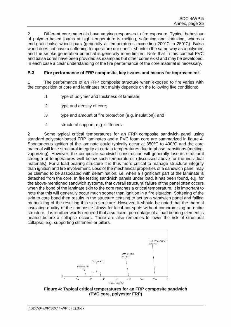
Figure 1: Illustrations of an FRP composite sandwich panel composition 2 Another FRP composite structure is the single skin panel, consisting of one single fibre reinforced laminate. Other FRP designs are also viable, e.g. triple skin (two cores and three laminates). The composite design could also include stiffeners.
SDC 4/WP.5 Annex, page 23
I:\SDC\04\WP\SDC 4-WP 5 (E).docx
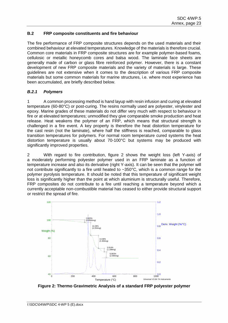
B.2 FRP composite constituents and fire behaviour The fire performance of FRP composite structures depends on the used materials and their combined behaviour at elevated temperatures. Knowledge of the materials is therefore crucial. Common core materials in FRP composite structures are for example polymer-based foams, cellulosic or metallic honeycomb cores and balsa wood. The laminate face sheets are generally made of carbon or glass fibre reinforced polymer. However, there is a constant development of new FRP composite materials and the variety of materials is large. These guidelines are not extensive when it comes to the description of various FRP composite materials but some common materials for marine structures, i.e. where most experience has been accumulated, are briefly described below. B.2.1 Polymers 1 A common processing method is hand layup with resin infusion and curing at elevated temperature (60-80°C) or post-curing. The resins normally used are polyester, vinylester and epoxy. Marine grades of these materials do not differ very much with respect to behaviour in fire or at elevated temperatures; unmodified they give comparable smoke production and heat release. Heat weakens the polymer of an FRP, which means that structural strength is challenged in a fire event. A key property is therefore the heat distortion temperature for the cast resin (not the laminate), where half the stiffness is reached, comparable to glass transition temperatures for polymers. For normal room temperature cured systems the heat distortion temperature is usually about 70-100°C but systems may be produced with significantly improved properties. 2 With regard to fire contribution, figure 2 shows the weight loss (left Y-axis) of a moderately performing polyester polymer used in an FRP laminate as a function of temperature increase and also its derivative (right Y-axis). It can be seen that the polymer will not contribute significantly to a fire until heated to ~350°C, which is a common range for the polymer pyrolysis temperature. It should be noted that this temperature of significant weight loss is significantly higher than the point at which aluminium is structurally useful. Therefore, FRP composites do not contribute to a fire until reaching a temperature beyond which a currently acceptable non-combustible material has ceased to either provide structural support or restrict the spread of fire.
Figure 2: Thermo Gravimetric Analysis of a standard FRP polyester polymer
3 The resins referred to above are all combustible and with comparable smoke production and heat release. There are also numerous modified resin systems that can provide better fire performance in terms of fire, smoke and toxic gas formation properties, sometimes at penalty of processing properties, mechanical properties or increased fire smoke production.
B.2.2 Fibres and reinforcements
1 When it comes to reinforcing fibres, E-glass and carbon fibres are currently most common. Polymeric fibres such as aramids (e.g. Kevlar and Twaron) are also used and other fibre types may be developed in the future.
2 E-glass fibres have been common mainly due to a good strength to cost ratio. E-glass fibres remain unaffected in fire until heated to about 830°C when viscous flow starts. Nonetheless, mechanical properties such as strength and stiffness decrease from around 500°C.
3 Carbon fibres are more heat resistant than glass fibres and are also common. They are unaffected by temperatures up to about 350°C and oxidize at a temperature of 650°C to 700°C (i.e. far above the temperature at which typical resins decompose). In addition, carbon fibre mats exhibit better heat distribution properties than glass fibres, which can avoid the occurrence of "hot spots".
4 While the polymer may contribute to the fire and increase its severity, the reinforcing fibres do not normally add to the fire intensity. On the contrary, as they often are quite inert, they serve as a temperature barrier and thermal insulator. However, a hazard is the possibility of fibres being spread to the environment from a fire event. Such fibres are known to cause skin/throat/eye irritation in the vicinity of a fire.
B.2.3 Core materials
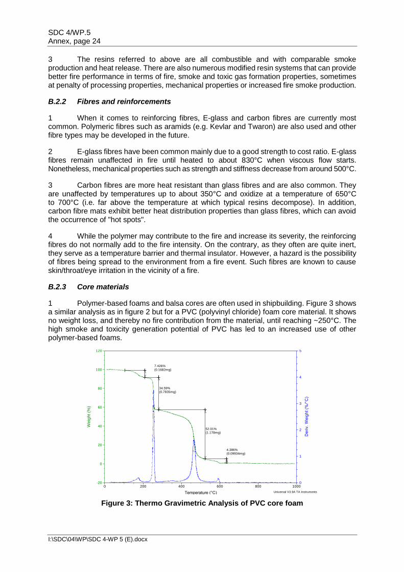
1 Polymer-based foams and balsa cores are often used in shipbuilding. Figure 3 shows a similar analysis as in figure 2 but for a PVC (polyvinyl chloride) foam core material. It shows no weight loss, and thereby no fire contribution from the material, until reaching ~250°C. The high smoke and toxicity generation potential of PVC has led to an increased use of other polymer-based foams.
Figure 3: Thermo Gravimetric Analysis of PVC core foam
7.426%(0.1682mg)
34.59%(0.7835mg)
52.01%(1.178mg)
4.386%(0.09934mg)
0
1
2
3
4
5
De
riv.
We
igh
t (%
/°C
)
-20
0
20
40
60
80
100
120
We
igh
t (%
)
0 200 400 600 800 1000
Temperature (°C)
Sample: BR intergard cellplastSize: 2.2650 mgMethod: High Resolution Dynamic
2 Different core materials have varying responses to fire exposure. Typical behaviour of polymer-based foams at high temperature is melting, softening and shrinking, whereas end-grain balsa wood chars (generally at temperatures exceeding 200°C to 250°C). Balsa wood does not have a softening temperature nor does it shrink in the same way as a polymer, and the smoke generation potential is generally more limited. Note that in this context PVC and balsa cores have been provided as examples but other cores exist and may be developed. In each case a clear understanding of the fire performance of the core material is necessary.
B.3 Fire performance of FRP composite, key issues and means for improvement
1 The performance of an FRP composite structure when exposed to fire varies with the composition of core and laminates but mainly depends on the following five conditions:
.1 type of polymer and thickness of laminate;
.2 type and density of core;
.3 type and amount of fire protection (e.g. insulation); and
.4 structural support, e.g. stiffeners.
2 Some typical critical temperatures for an FRP composite sandwich panel using standard polyester-based FRP laminates and a PVC foam core are summarized in figure 4. Spontaneous ignition of the laminate could typically occur at 350°C to 400°C and the core material will lose structural integrity at certain temperatures due to phase transitions (melting, vaporizing). However, the composite sandwich construction will generally lose its structural strength at temperatures well below such temperatures (discussed above for the individual materials). For a load-bearing structure it is thus more critical to manage structural integrity than ignition and fire involvement. Loss of the mechanical properties of a sandwich panel may be claimed to be associated with delamination, i.e. when a significant part of the laminate is detached from the core. In fire testing sandwich panels under load, it has been found, e.g. for the above-mentioned sandwich systems, that overall structural failure of the panel often occurs when the bond of the laminate skin to the core reaches a critical temperature. It is important to note that this will generally occur much sooner than ignition in a fire situation. Softening of the skin to core bond then results in the structure ceasing to act as a sandwich panel and failing by buckling of the resulting thin skin structure. However, it should be noted that the thermal insulating quality of the composite allows for local hot spots without compromising an entire structure. It is in other words required that a sufficient percentage of a load bearing element is heated before a collapse occurs. There are also remedies to lower the risk of structural collapse, e.g. supporting stiffeners or pillars.
Figure 4: Typical critical temperatures for an FRP composite sandwich (PVC core, polyester FRP)
SDC 4/WP.5 Annex, page 26
I:\SDC\04\WP\SDC 4-WP 5 (E).docx
B.3.1 Structural fire performance of FRP composite structures 1 FRP composite can never fulfil "A" class requirements as defined by SOLAS, since "A" implies "non-combustible" according to SOLAS regulation II-2/3.2. It further implies 60 minutes fire resistance, represented by a temperature rise in a large furnace according to the standard temperature-time curve, as defined by the ISO. FRP composite and metallic construction materials differ conceptually from a fire safety point of view. Not only from a reaction to fire perspective (ignitability, smoke and heat production) but also from a resistance to fire perspective (structural integrity and heat transfer). In the SOLAS requirements for fire resistance, metallic materials are expected to keep the temperature increase at the unexposed side of the bulkhead or deck in the standardized fire test below ~200˚C for 0, 30 minutes or 60 minutes, depending on the requirements for the particular space. The motive is to control the risk for fire spread to compartments adjacent to the fire compartment. A steel construction could still be load carrying for a long time after such temperatures are reached, whereas e.g. an aluminium construction would start to lose its structural strength at about 200˚C. A steel construction is therefore allowed with insulation on one side of the division, whereas aluminium constructions must be insulated on both sides. The same would be true also for FRP composites. 2 An FRP composite is a good thermal barrier. The fundamental condition for the FRP composite to achieve structural integrity "equivalent" to an A-class division is therefore not the temperature requirement at the unexposed side but that structural resistance is maintained for 60 min. As discussed above, an FRP composite structure will generally start to lose structural strength below 200˚C, and an FRP composite deck or bulkhead would therefore start to lose its structural integrity long before the temperature at the unexposed side approaches 200˚C. Thus, an FRP composite construction generally achieves SOLAS regulation II-2/9 "Containment of fire" much better than metallic materials due to its insulating capacity but has problems to fulfil SOLAS regulation II-2/11 "Structural integrity". Therefore, if structural collapse due to heat in an FRP composite construction can be avoided, the FRP composite design has a major advantage to metallic materials since fire spread due to heat transfer is a much lower risk in FRP composite than in metallic materials. 3 To achieve structural resistance in FRP, it is important to keep temperatures down, which is achievable through insulation or cooling. Structural fire performance may also be achieved by structurally redundant design, e.g. by using pillars, stiffeners or sandwich panels with over-capacity (e.g. triple skin panels designed so that half of the structure is sufficient to carry the design load). If redundancy of the constructions' load-bearing capacity is incorporated in the design, a fire could be well contained within the fire enclosure for a long time before spreading to other areas through the structure. 4 While structural performance is maintained, a fire will actually be better contained than in a prescriptive steel design since the insulating capacity of the composite will add significantly to the total insulating capacity of the construction. Since the heat is well kept within the fire enclosure, the overall temperature may also be higher compared to in a steel enclosure. Thus, a more intense fire with higher temperatures is possible using an FRP composite construction but the fire is more localized and less likely to spread due to heat transfer than in a metallic construction. The high temperatures motivate water based extinguishing systems since inertion by evaporated water is well facilitated. 5 If active and passive risk control measures fail and the fire falls out of control, a heat induced structural collapse could occur. The FRP composite could then also take part in the developing fire.
SDC 4/WP.5 Annex, page 27
I:\SDC\04\WP\SDC 4-WP 5 (E).docx
B.3.2 Firefighting of FRP composite structures 1 The high insulation capacity also affects the way of fighting fires in the construction material. In general when a fire appears on a vessel, water cooling of boundary surfaces of the fire enclosure is a basic strategy in maritime firefighting. When using FRP composites instead of metallic materials, such cooling is more or less meaningless since the outer surfaces of the fire room will have very low temperatures for a long time and also, the insulating capacity of the material will make such construction cooling ineffective. Instead, firefighting must take place inside the fire enclosure. Suitable firefighting equipment is already in use, such as the Cutting Extinguisher or small pre-fabricated inlets for nozzles which allow firefighting without entering the room. This is further discussed in 3.10 (regulation 10 – Firefighting). 2 The combustion of FRP composites is dependent on a thermal breakdown of organic molecules in the material. The insulating quality of the material will initially create a very steep temperature gradient in the material when subjected to a fire. If the material is cooled down, the production of combustible gases is hindered and the fire is stopped. This cooling should be applied to the hot surface. Empirical testing has shown that early application of water (which also requires fast detection) on a burning surface will quench the pyrolysis reactions in the FRP composite quite quickly. 3 If the fire has given sufficient heat exposure for the FRP composite to reach pyrolysis temperatures also deeply within the construction, fire tests have shown that continuous cooling may be necessary to prevent re-ignition. In particular, the core works as a thermal barrier, both in heat exposure and during cooling. Thus, for efficient firefighting it is beneficial if surfaces within a fire enclosure are cooled down as soon as possible. Active systems with quick response could therefore be useful. 4 A gaseous extinguishing system should be avoided since it will not provide the necessary cooling of the material at the surface. See also the discussion in section B.3.1 concerning evaporation advantages in well-insulated enclosures. B.3.3 Exterior surfaces in FRP composite 1 Exchanging traditional external steel surfaces for combustible FRP composite will give a fire the ability to propagate vertically if a window breaks or if an external door is left open. The fire can then potentially spread between decks and fire zones. This issue has been given much attention and full scale tests have been carried out in order to find suitable mitigating measures. Producing FRP face sheets with low flame-spread characteristics or installing a drencher system for external surfaces are alternatives to avoid fire spread. Fire rated windows and doors are other fire safety measures that could be relevant. It may also prove necessary to provide some kind of structural redundancy, as described above, addressing external fire exposure. B.3.4 Steel-FRP joints 1 An important area for an assessment of fire safety of FRP elements is the steel-FRP joints. A hazard associated with steel-FRP joints is the possibility of conduction of fire induced heat in the steel structure to an adhesive joint. If the adhesive reaches a critical temperature, the joint will fail. Furthermore, there are combined effects of differences in thermal expansion and other properties (e.g. heat conductivity, elastic modulus, combustibility) which could cause loss of structural and fire integrity.
SDC 4/WP.5 Annex, page 28
I:\SDC\04\WP\SDC 4-WP 5 (E).docx
2 Steel-FRP joints must be properly assessed to ensure that they are sufficiently protected from fire and heat deterioration. The assessment of steel-FRP joints should be part of the SOLAS regulation II-2/17 assessment and can include performance of fire tests. 3 Furthermore, it must be ensured that the structural fire integrity of the steel-FRP joint is maintained throughout its service life.
SDC 4/WP.5 Annex, page 29
I:\SDC\04\WP\SDC 4-WP 5 (E).docx
APPENDIX C
RECOMMENDATIONS REGARDING THE ASSESSMENT Introduction When assessing against SOLAS chapter II-2, regulation 17, an analysis shall show that an equivalent level of safety is achieved by the alternative design and arrangements with regard to introduced fire hazards. Guidelines for such analysis are found in MSC/Circ.1002, as amended by MSC.1/Circ.1552. However, when considering FRP composite structures, it may also be relevant to consider MSC.1/Circ.1455 which contains guidelines that have been developed to provide a consistent process for the coordination, review and approval of alternative design and arrangements in general, i.e. not only fire safety. This may be particularly appropriate when the use of FRP composite affects other aspects of safety than those related to fire. Further assistance may be found in guidance notes for MSC/Circ.1002, as amended by MSC.1/Circ.1552 and in guidelines on fire safety engineering applied to buildings. Below follow discussions on the required method for analysis, evaluation and approval of FRP composite structures, with regard to uncertainty treatment, sophistication and the practical process. Reference is made to the guidelines referenced in SOLAS, MSC/Circ.1002, as amended by MSC.1/Circ.1552, and also to MSC.1/Circ.1455. It is particularly pointed out that the assessment must stand in relation to the current scope of the proposed design and arrangements; a simple and well-protected structure in FRP composite should not require a complicated or time-consuming assessment. C.1 Uncertainty treatment 1 Even the most detailed risk assessment contains limitations; uncertainties are involved throughout the whole process. The uncertainties that arise when determining the frequencies and probabilities of events are often perceived as the dominating sources of error. Data is insufficient or not fully relevant for the particular events. Common reasons are that statistics have simply not been recorded or that the data is aged and does not comprise updates in legislation and novel technology. However, even if statistical information is often considered to be "the truth", it should be handled with care since the figures are always changing and may have great errors. Furthermore, statistics can give an image of something that has happened in the past but evaluations of novel ship designs need to be carried out before the ship is put into practice, which implies that statistical data will not be available for such parts of the ship. A general statistical representation may be available for the prescriptive design but the fire risk of the alternative design and arrangement needs to be calculated from knowledge. 2 Attempting to compare a calculated risk of alternative design and arrangements with a statistical representation of a prescriptive design, or an absolute risk criterion, may become extremely uncertain since the different approaches contribute with fundamentally different uncertainties. It could therefore be recommendable to carry out a relative risk assessment, as described in MSC/Circ.1002, as amended by MSC.1/Circ.1552, even when carrying out a SOLAS regulation II-2/17 assessment at a more sophisticated level. Thereby, uncertainties can be minimized by founding the risk estimations of the ship designs on similar assumptions (e.g. in models, expert judgement, statistical data, etc.). In order to expose the differences in fire safety it is also recommendable that the assessment concerns only the alternative design and arrangements and thereby relevant parts of the ship (a risk measure for the ship as a whole may give a wrong representation of the safety).
SDC 4/WP.5 Annex, page 30
I:\SDC\04\WP\SDC 4-WP 5 (E).docx
3 When determining consequences of events, uncertainties depend on how systematic and detailed the approach is. Models used when estimating the consequences and the experience in the expert group are also sources of uncertainties. In the hazard identification, uncertainties are also often linked to the method used, how detailed it is and the competence of the expert group examining the systems. Lack of routines, knowledge and experience are drawbacks which need to be considered when designing a ship with novel technology. The uncertainties can result in missing or wrong scenarios when identifying hazardous events, which can have great effects on the proceeding analysis. A common feature of all the steps of the risk assessment is that many simplifications are made in order to model complicated systems. Much because of the complex matter of assessing the impact of human behaviour when modelling, they tend to be focused on machines and technical components. Leaving the effects of organizational aspects, safety management systems and operator actions outside the scope of the risk assessment will, however, not reduce uncertainties. C.2 Required method 1 Many different methods for risk assessment, of varying sophistication, can be used to evaluate uncertainties in a ship design, which is the focus when adopting a risk-based approach. All ship designs contain uncertainties and all risk assessments contain uncertainties. As a result, all decisions will be made under some measure of uncertainty. If a risk assessment would result in an absolute certain probability density function of the possible consequences, a decision would be truly "risk-based". However, since uncertainties cannot be eliminated, it is important to analyse them and to appraise the effects of uncertainties on the result and the total effect when these uncertainties are considered. Methods for risk assessment are often classified based on the inclusion of quantitative measures (qualitative-quantitative) or on the consideration of the likelihood of outcomes (deterministic-probabilistic). A more suitable classification includes the previous features but depends on how uncertainties are treated with varying thoroughness. 2 The guidelines in MSC/Circ.1002, as amended by MSC.1/Circ.1552, outline a plausible worst-case approach for analysis and evaluation which can be described as a deterministic risk assessment. This kind of consequence analysis, commonly referred to as "engineering analysis", is described in several engineering guides to performance-based analysis of fire protection in buildings, which have formed the basis for the guidelines. MSC/Circ.1002, as amended by MSC.1/Circ.1552, makes clear that the scope of the analysis depends on the extent of deviations from prescriptive requirements and on the extent of the alternative design and arrangements. However, increased uncertainties do not only increase the scope of the analysis but also affect the required accuracy and sophistication of the method for verification of safety. A more sophisticated approach will further increase the engineering efforts but may be necessary if safety margins are to be kept reasonable and risks are to be properly managed when for example deviations are numerous, significant or concern many areas or when the design and arrangements are large, complex, novel or outside the scope of prescriptive requirements. Therefore, the approach outlined in MSC/Circ.1002, as amended by MSC.1/Circ.1552, may or may not be sufficient to adequately assess fire safety. Furthermore, if the case is simple, a less complicated kind of risk assessment should be sufficient. Therefore, MSC/Circ.1002, as amended by MSC.1/Circ.1552, "only" presents guidelines; the required sophistication of the method used to assess safety depends on whether it is sufficient to describe the current design and arrangements in terms of fire safety. The adaptability of the method used to verify fire safety and its dependence on the current scope is clearer in MSC.1/Circ.1455 (paragraph 4.13.2). Since the term "engineering analysis" refers to a certain kind of risk assessment, the more general term "SOLAS regulation II-2/17 assessment" is used in these guidelines.
SDC 4/WP.5 Annex, page 31
I:\SDC\04\WP\SDC 4-WP 5 (E).docx
3 Moving to SOLAS regulation II-2/17, the stated ultimate requirement for alternative design and arrangements is sufficient safety; an alternative design and arrangements shall be at least as safe as if prescriptive requirements were complied with (regulation II-2/17.3.4.2). If the scope of the deviations posed by the alternative design and arrangements is great it may be relevant to carry out an assessment at a higher level and determine an index of safety for the whole (or a considered part of the) ship. However, if effects on safety can be managed within the areas of one or a few regulations separately, this will allow for an assessment at a lower level (e.g. limited to evaluations of fire growth potential or containment of fire). This is also why it was decided to have regulation II-2/17.2.1 read: "provided that the design and arrangements meet the fire safety objectives and the functional requirements", without mentioning whether it is the functional requirements in SOLAS regulation II-2/2 or in any other regulation. "Minor" alternative design and arrangements should be possible to analyse and compare to single affected functional requirements of deviated regulations. As long as those functional requirements are met it may not be necessary to evaluate safety at a higher level through the overall fire safety objectives and functional requirements. However, this requires that risk control measures are found which target potential deficiencies in the areas of the individual deviated regulations. 4 It should be noted when considering FRP composite structures that a sole ASET-RSET evaluation, common in fire safety engineering, may provide an insufficient assessment. Effects on safety from use of FRP composite may go beyond what is captured by such assessment, e.g. effects appearing after escape from the fire or disproportionate damage. In any case, it should be proven that the ship can survive a set of relevant design fires and be its own lifeboat. The design fire scenarios must be specified to represent all the affected safety barriers, i.e. not only those presented as functional requirements in SOLAS, as further elaborated below. C.3 Establishment of approval basis 1 Modern ships (in particular passenger ships) are built with several fire safety functions or barriers. This will provide an integrated and redundant system that takes into account that some safety systems do not work as intended. A ship (partly) built of FRP composite structures should provide similar robustness and the design process should document that safety system can fail without loss of important safety functions or disproportionate consequences. However, all safety barriers are not clearly stated in the regulations and may be hard to identify. 2 According to SOLAS regulation II-2/17, alternative design and arrangements for fire safety should provide a degree of safety at least equivalent to that achieved by compliance with the prescriptive requirements. To form an approval basis, it is stated that the SOLAS regulation II-2/17 assessment should include an identification of the prescriptive requirement(s) with which the alternative design and arrangements will not comply (regulation II-2/17.3.2). This is also a foundational part in MSC/Circ.1002, as amended by MSC.1/Circ.1552, where it is stated that the regulations affecting the proposed alternative design and arrangements, along with their functional requirements, should be clearly understood and documented (paragraph 5.1.2). This is further stressed in paragraph 4.3.4, where it is stated that the preliminary analysis should include a clear definition of the regulations which affect the design and a clear understanding of the objectives and functional requirements of the regulations (i.e. the purpose statement in figure 5). The objectives and functional requirements of the deviated prescriptive requirements can thereafter be used (along with the fire safety objectives) to define performance criteria, as described in paragraphs 4.4 and 6.3.2 of the Guidelines on alternative design and arrangements for fire safety (MSC.1/Circ.1002, as amended by MSC.1/Circ.1552) and in regulation II-2/17.3.4.
SDC 4/WP.5 Annex, page 32
I:\SDC\04\WP\SDC 4-WP 5 (E).docx
3 When FRP composite is used, the fundamental deviations concern requirements on non-combustibility. However, due to limitations in current regulations, an identification of deviated prescriptive requirements and their associated purpose statements may not form a sufficient basis to evaluate the safety of FRP composite ship designs. The regulations are based on assumptions regarding the design and arrangements and therefore not all safety requirements are apparent. In particular, many requirements are made up around steel designs, leaving many implicit requirements unwritten. Therefore, use of FRP composite will affect fire safety in many ways, some of which are not covered by the fire safety regulations. An approval basis for equivalent safety may therefore not be sufficiently defined based only on deviations from prescriptive requirements, which is clearer in MSC.1/Circ.1455 (paragraph 4.7.1) than in MSC/Circ.1002, as amended by MSC.1/Circ.1552 (paragraph 5.1.2). 4 Depending on the scope of the proposed alternative design and arrangements, additional investigations may be called for to consider how the implicit level of fire safety represented in the Convention is affected. This may be relevant for an assessment of any design and arrangements which are truly novel (not simple extensions of the corresponding prescriptive requirements) since all hazards are not addressed by the Convention. A simple comparison with existing prescriptive requirements may not be sufficient and the assessment may therefore require special attention. 5 Investigations of effects on the implicit level of fire safety, or identification of missing requirements, can also be claimed necessary regardless of the novelty of the proposed alternative design and arrangements. To further complicate the comparison of safety levels, many prescriptive requirements have unclear connections with the purpose statements of their regulations and with the fire safety objectives of the fire safety chapter, which are supposed to define "fire safety". Some functional requirements could, for example, be claimed missing based on the prescriptive requirements and for some functional requirements listed at the beginning of regulations there are no associated prescriptive requirements. Deviation from one prescriptive requirement may affect the achievement of a functional requirement of a different regulation, etc. 6 A SOLAS regulation II-2/17 assessment involving FRP composite structures, as any SOLAS regulation II-2/17 assessment, must be sufficient to describe the introduced novelty in terms of fire safety. Determining the approval basis only based on deviated prescriptive requirements may not be sufficient and additional investigations of effects on the implicit level of fire safety may be necessary. These guidelines attempt to clarify such potential explicit and implicit effects on fire safety when using FRP composite compared to what is implied by the prescriptive requirements from a broad perspective in section 3 (Important factors to consider when evaluating FRP composite structures with starting point in the regulations of SOLAS chapter II-2). However, it could also be the case that further investigations are needed regarding how the proposed design and arrangements affect the fire safety implied by prescriptive requirements. Investigations could, for example, be carried out to clarify effects on the fire safety objectives and functional requirements of the fire safety chapter, effects on the structure of the fire safety (effects on the source, exposure or effect on part of the fire protection), effects on properties of the fire protection (e.g. effects on the flexibility, sensitivity, complexity, vulnerability, reliability or human intervention) or effects on fire development (effects on a fire in the incipient, growth, fully developed or decay phase). There are also many established methods for hazard identification which may be used.
SDC 4/WP.5 Annex, page 33
I:\SDC\04\WP\SDC 4-WP 5 (E).docx
7 In order to manage all the identified pros and cons of the alternative design and arrangements with regard to fire safety, it is also suggested that they are managed in a better way than the way in which it is described in MSC/Circ.1002, as amended by MSC.1/Circ.1552 (paragraphs 5.2.1.2 and 5.2.1.3), e.g. by collection and rating in a risk-based presentation, such as a ProCon List or Risk Matrix. This will be of significant value when forming fire scenarios. In general, when novel design and arrangements are managed, it is recommendable to have a larger focus on the initial stages of the SOLAS regulation II-2/17 assessment, particularly on the identification, collection, rating and selection of fire hazards. C.4 Approval process It should be stressed that the sophistication of the risk assessment may vary depending on the scope of the proposed design and arrangements, so may the practical process of the assessment. MSC/Circ.1002, as amended by MSC.1/Circ.1552, describes an approach where the assessment is reviewed at two stages by formal approval of reports. The guidelines in MSC.1/Circ.1455 include the Administration more in the process by putting a larger focus on monitoring and having review and approval of the assessment in several more but smaller stages. Regardless of which guidelines are referred to, it should be emphasized that the actual process may include more steps than in the guidelines but it may also be significantly simplified. For example, proposing the use of FRP composite for interior structures, a limited part of the ship or structures which are ubiquitously thermally insulated, may not require a lengthy, detailed or very time-consuming assessment.
SDC 4/WP.5 Annex, page 34
I:\SDC\04\WP\SDC 4-WP 5 (E).docx
APPENDIX D
FIRE TESTING OF FRP COMPOSITE
Introduction
Many of the fire safety regulations in SOLAS stand in correlation with performance in fire tests. Some relevant characteristic parameters which are currently measured are:
.1 spread of flames;
.2 evolved effect and energy;
.3 combustibility;
.4 smoke generation;
.5 toxicity; and
.6 structural resistance to fire.
These parameters are measured in different ways depending on the represented fire risk scenarios and with various criteria depending on the hazards involved. The different tests have not developed with particular attention to FRP composite constructions but may still be applicable, even if certain considerations may be necessary. However, there is already a market for FRP composite constructions in naval and commercial maritime applications, particularly for high-speed crafts (HSC). For this purpose, new regulations and standardized tests applying to such materials have been implemented in the International Code of Safety for High-Speed Craft (HSC Code). It includes several significant differences with regard to the safety organization, available egress time and requirements for the materials, but it may still be relevant to refer to the related fire tests when considering FRP composite structures in SOLAS ships. Any standardized or experimentally set up test may be referred to as a SOLAS regulation II-2/17 assessment but may require evaluations of the test results. Assessments by experts may also allow the transfer of test results from one FRP composite composition to another.
Below follows a discussion on the limitations of safety validation through tests in general and on uncertainties that need to be considered when using current fire test procedures to validate FRP composite in particular. Thereafter, the most relevant fire tests prescribed by SOLAS and the HSC Code are briefly described, with focus on the particularities with testing FRP composite. For some FRP composite constructions it may be necessary to look beyond the approved fire test procedures and consider other standardized tests or tailored experimental tests, which are discussed at the end of this chapter.
D.1 Uncertainties when using tests to validate FRP composite
1 Testing is a good tool to evaluate whether a construction performs satisfactorily in a certain situation. Full-scale testing is the method that typically will give the most accurate results on how a design will perform, even if natural variations are always present. Since it would be very costly to evaluate all possible scenarios in full-sized tests, some characteristic parameters are generally investigated in certain ways during exposure to plausibly worst-case scenarios. The overall safety performance is therefore assumed to stand in correlation with the performance in these characteristic tests, derived from knowledge of fire dynamics and behaviour of materials when exposed to fire.
SDC 4/WP.5 Annex, page 35
I:\SDC\04\WP\SDC 4-WP 5 (E).docx
2 However, FRP composite and steel, which it generally replaces, are inherently very different. Some general particularities with FRP composites are the anisotropy and inhomogeneity, which may give variations in test results depending on the positioning. Another potential difficulty is that the different plies of resin impregnated fibre cloths might delaminate during testing. Produced gases will strengthen this tendency as they seek the outlet of "least resistance". The latter effect will not be captured in a small-scale test since the maximum travel distance for gases in the real fire will be much longer than in, e.g. a "Cone Calorimeter" test where the maximum "travel" distance is 5 cm. The "edge" effect will therefore be much more important in a small-scale test than in a full-sized test. Different remedies to problems related to scale are given in the literature and they include edge protection, which in the Cone Calorimeter could be the use of a sample holder that covers the edges completely or to vary the sample size or orientation. 3 Evaluation of two such diverse construction materials through the same tests may be claimed to be quite obtuse. Today's fire tests are generally constructed to measure some key properties reflecting different disadvantages of traditional (steel) constructions and ideally represent the performance of such constructions when exposed to a severe fire. However, some characteristics are left out in the tests because of the implicit benefits of traditional solutions. Therefore, implicit advantages may not be represented in the tests and may not be possible to evaluate. What must be considered further is also the uncertainty associated with performance criteria generally being binary, i.e. pass or fail. When evaluating designs through tests there is always a lowest level for passing the test, an acceptance criterion. Assurance of identical set-ups and measurements are obviously of greatest significance when tests are carried out by different people and at different labs in countries throughout the whole world. However, even without those uncertainties, a test says nothing about the performance not represented in the test, i.e. the performance of the sample if the load, temperature or time in the test increases by 10%, 20% or 50%. In general, the prescriptive fire tests of the International Code for Application of Fire Test Procedures, 2010 (2010 FTP Code) only give pass or fail. Therefore, no information is given on how the construction performed during the test or how long it could have performed with satisfaction. An example of this is the ability of steel bulkheads to withstand high temperatures before structural deterioration. It is because of the implicit advantages of steel, not visible in standardized tests, that there is an additional requirement for many structures to be made of steel or other equivalent material. However, when aluminium was introduced to merchant shipbuilding, it was necessary to address this in a better way. Aluminium was, according to regulations, considered as an alternative non-combustible material to steel. However, the relatively poor structural behaviour at elevated temperatures (aluminium does not burn but nevertheless melts in the non-combustibility test) highlighted the simplistic nature of the non-combustibility requirement. Aluminium structures were therefore generally required to be fitted with double sided insulation and were thereby considered equivalent to steel in this regard. Furthermore, when non-metal load-bearing structures are considered for HSC, they are subjected to an additional load during structural fire resistance tests in order for the structure to be considered equivalent to a metal construction. Therefore, there may be reason to assess whether the standardized tests fully reflect the risks and benefits of FRP composite structures in case of fire. Implicit properties beyond the tests need to be identified, which is one of the objectives behind these guidelines, and may require verification through additional tests.
SDC 4/WP.5 Annex, page 36
I:\SDC\04\WP\SDC 4-WP 5 (E).docx
D.2 Low flame-spread characteristics 1 The potential for flame spread of a material is tested in equipment where an irradiating panel provides heat input to a surface in order to initiate flaming combustion. The IMO typical example of such equipment is shown in figure 5. Fire is initiated where the distance between panel and sample is the shortest, i.e. where the irradiation intensity is the highest. The radiation level decreases at the test specimen from left to right in figure 5, and the extreme burning point to the right, i.e. the point with the lowest irradiation level for sustained combustion, is given as a measure of flame spread for the material. The speed of the flame front movement is also quantified in an appropriate way. There are also criteria regarding the peak heat release as well as of the total evolved effect.
Figure 5: Test for flame spread according to part 5 of the 2010 FTP Code 2 When testing FRP composite according to this procedure, it is important to comply with the requirement to test the specimen with end-use conditions. The material behind the tested surface material will significantly affect the fire behaviour. A well-insulating material behind a thin ply will keep much more of the heat at the surface and generally worsen the conditions for the tested surface material. Therefore, if the end-use is a sandwich panel, it is not appropriate to test only the surface laminate on a steel plate or directly in the sample holder. The equipment normally fits a 50 mm thick sample and for FRP composite it is recommendable to include as much of the composite material as possible in the sample holder. D.3 Generated effect and smoke in small scale 1 The HSC Code includes regulations for furniture and other components which require investigating fire behaviour on a small scale in the "Cone Calorimeter" test equipment defined in the standard ISO 5660 (shown in the schematic picture in figure 6). The 0.1 x 0.1 m specimen is horizontally positioned and subjected to irradiation from electrically heated surfaces above the tested material. Irradiation levels are typically in the range of 25 to 50 kW/m2.
SDC 4/WP.5 Annex, page 37
I:\SDC\04\WP\SDC 4-WP 5 (E).docx
Figure 6: Schematic picture of a Cone Calorimeter 2 Except from time to ignition, the standard ISO 5660 Cone Calorimeter test includes measurement of smoke (obscuration) and heat release under different radiant fluxes. There is a criterion for the peak heat release rate. The time integrated HRR signal provides the total heat release (THR), which must be limited and is a very important material fire characteristic. The HRR curve for such an experiment on a carbon fibre based composite laminate is shown in figure 7.
Figure 7: Small-scale experimental results from carbon FRP composite material D.4 Generated effect and smoke on a large scale 1 The criteria for the Cone Calorimeter are designed to correlate with a large scale "Room Corner" test scenario according to the standard ISO 9705. It is an important standardized piece of equipment for testing material potential for HRR and smoke, schematically pictured in figure 8. In this test, the material to be tested is mounted on walls and ceiling and a propane gas burner positioned in a corner of a full-scale room provides a 100 kW power output for 10 min, followed by a 300 kW output for an additional 10 minute period. The HRR and smoke production rate are continuously measured and the criteria that apply are similar to those in the Cone Calorimeter.
HRR for Carbon fibre based FRP in Cone Calorimeter experiment
0
50
100
150
200
250
300
0 50 100 150 200 250 300 350 400 450
time (s)
Eff
ect
(kW
/m2
SDC 4/WP.5 Annex, page 38
I:\SDC\04\WP\SDC 4-WP 5 (E).docx
Figure 8: Schematic view of ISO 9705 Room-Corner experimental set-up 2 The standard ISO 9705 test is important for marine applications as it is used in the 2010 FTP Code for experimental verification of FRM, "Fire Restricting Materials", used on HSC. On SOLAS ships requirements are more relaxed and surfaces are often coated with combustible paints that would not pass FRM requirements, in particular if applied to an FRP composite surface. The material behind the surface finish has a major impact on the test results and, due to the high thermal conductivity of FRP composite, this test is therefore rather challenging for FRP composite systems. Furthermore, droplets and debris must also be considered according to the test requirements. It is thus crucial that FRP composite materials are tested in end-use conditions. It should be noted that, in comparison with the test for surface flammability, the room corner test is not only full scale but also includes further complexities, in particular with regard to effects of enclosure fire dynamics. Flames and smoke are collected in the room and heat up surfaces in a different way. These reradiate between each other. The effects from enclosure fire dynamics also generally make the test harder to pass than the test for spread of flame; that is, materials that pass the room corner test generally also pass the test for spread of flame. For exterior combustible surfaces, the ability to manage effects from enclosure fires could be claimed irrelevant, as these effects will not appear out in the open on exterior surfaces. Therefore, for such areas a different test could be more suitable.
D.5 Non-combustibility
The previously described test methods have been presented in an approximate order of difficulty with regard to fire behaviour of the materials. The ultimate fire-related material quality is non-combustibility, determining whether the material is at all considered combustible. An accepted method for measuring combustibility is the fire test given in part 1 of the 2010 FTP Code (see figure 9). A specimen is exposed to 750°C in a cylindrical furnace where temperature increase, flames and weight loss are measured to determine combustion.
SDC 4/WP.5 Annex, page 39
I:\SDC\04\WP\SDC 4-WP 5 (E).docx
Figure 9: Combustibility test equipment according to part 1 of the 2010 FTP Code D.6 Smoke generation and toxicity 1 In evaluations of materials it is often relevant to combine properties of fire behaviour (fire growth, fire spread, etc.) with materials' potential for smoke generation and toxicity. For maritime applications, the "smoke box" is used for smoke and toxicology measurements, based on part 2 of the 2010 FTP Code. For SOLAS applications this test is only required if results in the test for spread of flame are insufficient. In this method, a 0.5 m3 closed cubic box (figure 10) is used for exposing a small (75 mm x 75 mm) sample for irradiation and measuring continuously gases and smoke opacity in the box. Criteria concern maximum amount of smoke produced and maximum concentrations of the following gaseous species: CO, HCl, HF, NOx, HBr, HCN and SO2, as given in the 2010 FTP Code. The test proceeds for 10 minutes if a maximum has been observed in the smoke obscuration level; otherwise the test proceeds for another 10 minutes. The toxicity levels when the smoke obscuration reached its peak value are used as the result from the test.
Figure 10: Smoke box equipment 2 In this test, materials generally produce more smoke before ignition than after they have ignited. The same applies to most gases, in particular CO levels which are significantly higher before ignition (the opposite applies for HCN). Therefore, FRP composite materials that have been treated to impede ignition and flame spread generally produce smoke and toxic gas in levels which may make it challenging to pass the test.
SDC 4/WP.5 Annex, page 40
I:\SDC\04\WP\SDC 4-WP 5 (E).docx
3 There is no requirement to test insulations, bulkhead panels and similar items for smoke and toxicity, since they are assumed to be non-combustible. However, regardless of whether a fire restricting material is used on top of an FRP composite panel, if a surface with low flame-spread characteristics is applied or if the FRP composite panel is left bare it could be claimed that it is the surface of the compartment which should be tested. End-use conditions apply also in this test method and as much of the FRP composite that fits in the 25 mm sample holder should then be included in the test. The long and significant heat exposure will cause materials underneath the potentially burning surface to thermally decompose. Even if the result is not the same as if the underlying materials were directly exposed, they will contribute to the generated smoke and toxic gases to an extent that is representable to the heat exposure in the test and in a fully developed fire.
D.7 Structural resistance
1 For load-bearing structures on SOLAS ships, structural resistance to fire is tested by exposing the sample to a well-defined temperature that increases over time. Typical standardized time-temperature curves are used as reference for the temperature in the furnace as depicted in figure 11.
Figure 11: Time-temperature curves used for testing of structural resistance 2 In the structural resistance test the sample insulation properties are tested, i.e. its ability to withstand heat while keeping the temperature down at the unexposed side of the sample. The required performance time in a test and the demand for the backside temperature depends on type of test and type of classification. An example of a structural resistance test, used e.g. for walls, doors, bulkheads, etc., is illustrated in figure 12, where a load-bearing wall with a window is exposed to heat. Another test for a door construction is shown in figure 13.
Figure 12: Large-scale structural fire resistance test of a window
Fire exposure
0
200
400
600
800
1000
1200
1400
0 30 60 90 120 150 180 210 240 270 300
Time (minutes)
Tem
pera
ture
(C
)
X2000
HC-curve
Standard curve
SDC 4/WP.5 Annex, page 41
I:\SDC\04\WP\SDC 4-WP 5 (E).docx
Figure 13: Insulation test of a door where thermocouples measure the temperature of the unexposed side during the heat exposure
3 As discussed above, for SOLAS applications there is no requirement in the test procedures to evaluate the construction load-bearing capabilities. In the HSC Code the divisions corresponding to A-class divisions in SOLAS are referred to as Fire Resisting Divisions (FRD). The main difference is the requirement for an A-class division to be constructed with non-combustible material, which does not apply to an FRD. The structural fire resistance test is basically identical to the test required for A-class divisions, except for an additional load-bearing requirement. This requirement implies that FRD decks and bulkheads shall withstand the standard fire test while subjected to transverse and in-plane loading, respectively. A FRD deck or bulkhead structure must sustain the specified static loading whilst exposed to fire in a large-scale furnace for 30 minutes or 60 minutes in order to be certified as an FRD30 or FRD60 division, respectively. 4 Loading during fire resistance tests may be highly relevant when evaluating FRP composite constructions for SOLAS ships. However, research has shown that it is more suitable to apply the design load than the relatively low static load (in accordance with part 11 of the FTP Code) when testing insulated FRP sandwich panel bulkheads. It is likely that a similar fire test procedure is suitable also for other FRP composite design concepts (e.g. non-insulated FRP bulkheads, different deck concepts) but this must yet be verified. Penetrations in FRP composite structures could reduce the load-bearing capacity and may call for testing of penetrations in load-bearing structures as well. Tests have been performed with certain FRP composite panels with holes that did not show any such effects. However, effects clearly depend on the made penetrations and on the safety margins included in the design. Fire resistance tests for penetrations on HSC are not performed with applied load.
Figure 14: Small-scale furnace for structural resistance tests 4 Small-scale test methods for structural resistance exist but are used in R&D projects or for product quality control. The maximum size of the tested sample in the small-scale furnace is 0.5 m x 0.6 m (figure 14), which is to be compared to a typical full-sized test as shown in
SDC 4/WP.5 Annex, page 42
I:\SDC\04\WP\SDC 4-WP 5 (E).docx
figure 12, where a 3 m x 3 m sample is being tested. In a SOLAS regulation II-2/17 assessment it may be relevant to refer to standards other than IMO test standards to evaluate fire-resistance (e.g. ISO 834-12 Fire resistance tests – Elements of building construction, Part 12: Specific requirements for separating elements evaluated on less than full scale furnaces and ISO 30021 Plastics – Burning behaviour – intermediate-scale fire-resistance testing of fibre reinforced polymer composites).
D.8 Additional testing
1 Throughout different research projects many experimental tests have been carried out. Except for tests according to all of the standardized test procedures described above, tests have, for example, been carried out for divisions' structural integrity in vertical and horizontal furnaces with various time, integrity requirements and loads (nominal load according to the HSC Code, design load and realistic load). Many solutions for doors, windows and penetrations have also been certified in such tests and different outfitting solutions have been tested in experimental tests with corresponding fire exposure. Fire growth has been evaluated for external combustible FRP composite surfaces based on a standardized test method for testing reaction to fire properties of building façade systems.1 In the tests, the performance of FRP composite surfaces protected with different passive or active measures were compared with a completely non-combustible surface (hence the multiple layers of paint on a steel ship were ignored). Performance criteria have been developed for external drencher systems to determine under which conditions a drencher may be effective when using FRP composite on external surfaces. Tests have also been performed based on the Guidelines for the approval of fixed pressure water-spraying and water based fire-extinguishing systems for cabin balconies (MSC/Circ.1268) which showed that a balcony sprinkler prevented a fully developed cabin fire from spreading to FRP composite surfaces on the balcony and on outboard sides of the ship.
2 Depending on the intended use of FRP composite further tests may be relevant, e.g.:
.1 a joint between steel and FRP composite could be fire tested to ensure that collapse will not occur due to heat conduction from fire in an underlying steel compartment;
.2 if insulation is used, it may be relevant to test FRP composite which is insufficiently insulated, e.g. a small or large-scale furnace test with 0.1 m x 0.1 m or 0.5 m x 0.5 m lack of insulation, or emergency repaired/modified; and
.3 structural integrity test of a composite deck exposed to fire from above.
3 It may also be claimed necessary to prove that an FRP composite material is not easily ignited. Even though restricted ignitability is required by functional requirements in SOLAS regulations, there is no IMO certifying test to show this property. However, EN ISO 11925-2, Reaction to fire tests – Ignitability of building products subjected to direct impingement of flame – Part 2: Single-flame source test or the Guidelines on fire test procedures for acceptance of fire-retardant materials for the construction of lifeboats (MSC/Circ.1006) provide possible test methods. EN ISO 11925-2 specifies a test method which measures the ignitability of building products when exposed to a small flame. Based on numerous fire tests with various FRP composite materials2, it has, however, been judged very
1 SP FIRE 105-External Wall Assemblies and Façade Claddings – Reaction to Fire
2 Fire Tests of FRP Composite Ship Structures, SP Technical Research Institute of Sweden,
likely that most exposed surfaces of untreated FRP composite (i.e. the laminate) would pass such a test. This can also be distinguished from the Cone Calorimeter test data in figure 7. The graph does not only show that the FRP composite may become involved in a significant fire but also that it resists the rather significant irradiation of 50 kW/m2 for at least one minute before becoming involved in a large fire. For reference, 15 to 20 kW/m2 towards the floor is often referred to as a criterion for when flashover is determined in an enclosure fire. A Molotov cocktail has, for example, been concluded not to be able to ignite the particular FRP composite surface tested in figure 7. In the aforementioned test method for ignitability of building products, the material is exposed to a flame the size of a match for 15 or 30 seconds. It can thereby be concluded that FRP composite surfaces generally have restricted ignitability and what could rather be a problem is fire spread if the surface is exposed to an already established fire. If considered relevant, the ignitability of various FRP composite surfaces may be evaluated through a test, e.g. according to the standard EN ISO 11925-2 or MSC.1/Circ.1006.
SDC 4/WP.5 Annex, page 44
I:\SDC\04\WP\SDC 4-WP 5 (E).docx
APPENDIX E
EXAMPLE OF ASSESSMENT PROCEDURE 1 In this appendix, examples of a SOLAS regulation II-2/17 assessment are presented with the ambition to guide the Administration in what to require from an assessment involving FRP composite structures. The following three general principles are used:
.1 protect internal structures against exposure to an indoor fire; .2 protect against fires exposing external surfaces; and .3 document performance of fire protection using primarily established test
procedures. 2 A design preview meeting is typically held between the client, coordinator of the assessment and the Administration prior to the start of the assessment in order to clarify the scope, objectives, process and roles of stakeholders. Then a design team is selected to mirror the complexity of the task, in the sense that the members should together possess all the necessary competencies to perform the assessment of fire safety. For example, experts in FRP composite materials, fire safety, fire testing, fire safety engineering, risk assessment, fire safety regulation, ship design and operation may all be relevant to include. Even if the design team should be formed at the beginning of the project, it may be necessary to expand it further along. The whole design team will not be part of all parts of the process but it is key that the design team is well represented at the hazard identification. It is also recommendable that the Administration is included in the hazard identification, as well as at key review meetings, as a witness to gain insight or to provide direct feedback on preliminary results. 3 An effective hazard identification requires that an investigation of potential challenges to regulations has been performed (see section 3 (Important factors to consider when evaluating FRP composite structures with starting point in the regulations of chapter II-2)) on the basis of a base alternative design, which must be well-defined at this stage. A base alternative design is the fire safety design and arrangements which all trial alternative designs have in common, including the introduced novelty and pre-determined safety measures. Different combinations of safety measures (risk control options) added to the base alternative design defines the trial alternative designs to be evaluated (see example below). 4 As an example, consider the deck house in figure 15 with FRP composite sandwich panel structures (composition as in figure 1). In the base alternative design the inside of the FRP composite surfaces are covered by thermal insulation to achieve 60 minutes of fire integrity according to the 2010 FTP Code, part 11. The fire integrity is maintained at openings and penetrations.
Figure 15: Example deck house structure of FRP composite
SDC 4/WP.5 Annex, page 45
I:\SDC\04\WP\SDC 4-WP 5 (E).docx
5 Since the structures are not made of non-combustible material, deviations to prescriptive requirements are found in SOLAS regulations II-2/9 and II-2/11. Regulation II-2/9 requires A-class divisions with 0 to 60 minutes fire insulation capability and regulation II-2/11 requires deckhouses to be constructed of steel or other equivalent material. By evaluation of the purpose statements, several more challenges are identified, particularly when considering the unprotected external surfaces (see section 3 (Important factors to consider when evaluating FRP composite structures with starting point in the regulations of chapter II-2)). Affected functional requirements may be identified as:
.1 restrict ignitability of combustible materials; .2 restrict the amount of combustible materials; .3 restrict the fire growth potential of combustible materials; .4 limit the quantity of smoke and toxic products released from combustible
materials during fire; .5 boundaries shall provide thermal insulation and integrity with due regard to
the fire risk of adjacent spaces; and .6 materials used in the ships' structure shall ensure that the structural integrity
is not degraded due to fire. 6 During the hazard identification a number of potential ignition sources and fuels may be identified inside and outside the deck house. With a deterministic (worst-case) approach, two design fire scenarios are defined to evaluate the fire safety of the deck house: a flashover fire in the generator space and a significant exterior hydrocarbon fire. Trial alternative designs are said to be formed by adding any combination of risk control measures (RCMs), identified as:
.1 provision of stiffeners on the inside of the exterior bulkheads (to provide structural integrity along with the unexposed laminate in case of an external fire);
.2 use of double sandwich panels (triple skin sandwich panels), where only half
are necessary to carry the design load (to structural integrity along with the unexposed laminate in case of an external fire);
.3 provision of a drencher system covering the external surfaces; .4 redundant supply unit for the drencher system; .5 provision of low flame-spread characteristics on external surfaces; and .6 automatic surveillance of closure of doors.
7 In quantifying effects on safety there are different approaches (see appendix D (Recommendations regarding the assessment)). Here, an approach where the ambition is to perform at least as well as a prescriptive design in all areas where fire hazards are introduced independently is exemplified; this implies that a sufficient safety margin is sought which by conservative safety measures allows to keep the complexity of the assessment at a minimum.
SDC 4/WP.5 Annex, page 46
I:\SDC\04\WP\SDC 4-WP 5 (E).docx
8 Regarding ignitability, this is only considered affected at external surfaces. A fire test is performed in accordance with the standard ISO 11925-2, a test method to evaluate the ignitability of building products when exposed to a small flame, which shows that ignitability is not a problem. A full-scale experimental fire test is performed for different RCMs applied to an FRP composite panel constructed as one of the external sides of the deck house. They show that RCM e above or pre-activation of RCM c prevents ignition during 20 minutes of significant fire exposure during the fire tests. This is argued sufficient with regard to the potential for external fire exposure and the organization of manual firefighting. Tests according to part 11 of the 2010 FTP Code are used to demonstrate that fire integrity, fire growth potential and smoke production are managed in case of a fully developed fire inside the spaces. Event tree analysis shows that function of door closing devices is key to prevent an interior fire to grow and spread. It is therefore included in all risk control options (RCOs), which are now concretized as:
.1 RCO A: RCMs a + c + d + f; .2 RCO B: RCMs b + c + d + f; .3 RCO C: RCMs b + c + d + f + extended detection system; .4 RCO D: RCMs c + d + f + extended detection system; and .5 RCO E: RCMs e, f.
9 RCO A and RCO B require that the drencher system is activated if structural integrity is not to deteriorate and therefore includes a redundant supply unit (RCM c). Smoke production may not be a problem on deck but it can be argued that fire growth is not properly managed. This may be handled by an extended detection system, providing quick and reliable activation of the drencher system, which was therefore added in RCO C. The question is then if the over-capacity in structural integrity provided by RCM b is necessary, hence RCO D. Without further elaborating on these issues, it is decided to present RCO E as the suggested final alternative design, since it cost-effectively is considered to cost-effectively provide a reliable solution. The performance criteria to better achieve safety functions where fire hazards have been introduced are thereby considered to be met.