American Association of State Highway Transportation Officials National Steel Bridge Alliance AASHTO/NSBA Steel Bridge Collaboration G2.2‐2016 Guidelines for Resolution of Steel Bridge Fabrication Errors
Transcript
American Association of State Highway TransportationOfficials National Steel Bridge Alliance AASHTO/NSBA Steel Bridge Collaboration
G2.2‐2016
Guidelines for Resolution of SteelBridge Fabrication Errors
G 2.2 GUIDELINES FOR RESOLUTION OF STEEL BRIDGE FABRICATION ERRORS I
FOREWORD
Errors occurring during the fabrication of steel bridges need to be recognized and corrected according to the situation. To achieve practical solutions, engineers need not only knowledge of design, material, and construction (including fabrication) specifications but also experience and good understanding of fabrication practices and limitations. This expertise varies among individuals, with very few having a sufficiently broad background to address all circumstances.
This document provides suggested guidelines in a form intended to assist engineers, inspectors, and fabricators, introducing the issues necessary for structurally and economically viable resolutions of fabrication errors. This document has been prepared as a guide and thus, much of the information is general in nature, representing a consensus of various positions of owners as well as fabricators to provide guidance and improve confidence in solutions to unusual but non-unique problems. Recommendations should not be considered as hard and fast rules.
DISCLAIMER
The information presented in this publication has been prepared in accordance with recognized engineering principles and is for general information only. While it is believed to be accurate, this information should not be used or relied upon for any specific application without competent professional examination and verification of its accuracy, suitability, and applicability by a licensed professional engineer, designer, or architect.
The publication of the material contained herein is not intended as a representation or warranty of the part of the American Association of State Highway and Transportation Officials (AASHTO) or the National Steel Bridge Alliance (NSBA) or of any other person named herein, that this information is suitable for any general or particular use or of freedom from infringement of any patent or patents. Anyone making use of this information assumes all liability arising from such use.
Caution must be exercised when relying upon other specifications and codes developed by other bodies and incorporated by reference herein since such material may be modified or amended from time to time subsequent to the printing of this edition. The authors and publishers bear no responsibility for such material other than to refer to it and incorporate it by reference at the time of the initial publication of this edition.
G 2.2 GUIDELINES FOR RESOLUTION OF STEEL BRIDGE FABRICATION ERRORS III
HIGHWAY SUBCOMMITTEE ON BRIDGES AND STRUCTURES, 2016 GREGG FREDRICK, Chair
BRUCE V. JOHNSON, Vice Chair JOSEPH L. HARTMANN, Federal Highway Administration, Secretary
PATRICIA J. BUSH, AASHTO Liaison ALABAMA, Eric J. Christie, William “Tim” Colquett, Randall B. Mullins ALASKA, Richard A. Pratt ARIZONA, David B. Benton, David L.
Eberhart, Pe-Shen Yang ARKANSAS, Charles “Rick” Ellis CALIFORNIA, Susan Hida, Thomas A.
Ostrom, Dolores Valls COLORADO, Behrooz Far, Stephen
Harelson, Jessica Martinez CONNECTICUT, Timothy D. Fields DELAWARE, Barry A. Benton, Jason
Hastings DISTRICT OF COLUMBIA, Donald L.
Cooney, Konjit C. “Connie” Eskender, Richard Kenney
FLORIDA, Sam Fallaha, Dennis William Potter, Jeff Pouliotte
GEORGIA, Bill DuVall, Steve Gaston HAWAII, James Fu IDAHO, Matthew Farrar ILLINOIS, Tim A. Armbrecht, Carl
Puzey INDIANA, Anne M. Rearick IOWA, Ahmad Abu-Hawash, Norman L.
McDonald KANSAS, Mark E. Hoppe, John P. Jones KENTUCKY, Mark Hite, Marvin Wolfe LOUISIANA, Arthur D’Andrea, Paul
Fossier, Zhengzheng “Jenny” Fu MAINE, Jeffrey S. Folsom, Wayne
Frankhauser, Michael Wight MARYLAND, Earle S. Freedman, Jeffrey
L. Robert, Gregory Scott Roby MASSACHUSETTS, Alexander K.
Bardow, Thomas Donald, Joseph Rigney
MICHIGAN, Matthew Jack Chynoweth, David Juntunen
MINNESOTA, Arielle Ehrlich, Kevin Western
MISSISSIPPI, Austin Banks, Justin Walker, Scott Westerfield
MISSOURI, Dennis Heckman, Scott Stotlemeyer
MONTANA, Kent M. Barnes, David F. Johnson
NEBRASKA, Mark Ahlman, Fouad Jaber, Mark J. Traynowicz
NEVADA, Troy Martin, Jessen Mortensen NEW HAMPSHIRE, David L. Scott,
Peter Stamnas NEW JERSEY, Xiaohua “Hannah”
Cheng, Nagnath “Nat” Kasbekar, Eli D. Lambert
NEW MEXICO, Ted L. Barber, Raymond M. Trujillo, Jeff C. Vigil
NEW YORK, Wahid Albert, Richard Marchione
NORTH CAROLINA, Brian Hanks, Scott Hidden, Thomas Koch
NORTH DAKOTA, Terrence R. Udland OHIO, Alexander B.C. Dettloff, Timothy
J. Keller OKLAHOMA, Steven Jacobi, Walter
Peters OREGON, Bruce V. Johnson, Tanarat
Potisuk, Hormoz Seradj PENNSYLVANIA, James M. Long,
Thomas P. Macioce, Lou Ruzzi PUERTO RICO, (Vacant) RHODE ISLAND, Georgette Chahine SOUTH CAROLINA, Barry W. Bowers,
Terry B. Koon, Jeff Sizemore SOUTH DAKOTA, Steve Johnson TENNESSEE, John S. Hastings, Wayne J.
G 2.2 GUIDELINES FOR RESOLUTION OF STEEL BRIDGE FABRICATION ERRORS V
ACKNOWLEDGEMENTS
The following individuals and organizations contributed the development of this document.
Regional Pooled Fund Study SPR-3 (083) and Technical Committee members. States participating: ID, IL, KS (Lead State), MI, MN, MO, MT, NH, NJ, NV, PA, TX, and WY. Principal investigator: Kim Roddis.
AASHTO/NSBA Steel Bridge Collaboration Task Group 5 (Repair) and Task Group 2 (Fabrication) members, including:
Kim Roddis, Chair TG5, George Washington University Heather Gilmer, Chair TG2, HRV Frank Adragna, TRC Engineering Camille Bernier, Canam Bridges Bob Bills, TUV Rheinland Frank Blakemore, Garver Brian Cavin, Wovt Industries Brandon Chavel, HDR, Inc. Robert Connor, Purdue University Steve Cook, Michigan DOT Chris Crosby, ISC Denis Dubois, HRV Steve Duke, Florida DOT Jon Edwards, DOT Quality Services Sammy Elsayed, MC Ironworks Behrooz Far, Colorado DOT Jamie Farris, Texas DOT Karl Frank, Hirschfeld Industries John Gast, ConWeld Rich Giusti, Jr., Haydon Bolts Jamie Hilton, KTA-Tator Bob Horwhat, Pennsylvania DOT
Joe Howard, St. Louis Screw & Bolt Mark Hurt, Kansas DOT Ken Hurst, Kansas DOT (retired) Adil Khan, Amec Foster Wheeler Brian Kozy, FHWA Paul Kulseth, Kansas DOT Al Laffoon, Missouri DOT (retired) Teresa Michalk, Texas DOT Ronnie Medlock, High Steel Russ Panico, Quality Management Company Duncan Paterson, HDR, Inc. Anna Petroski, DOT Quality Services Max Puchtel, AISC Buck Roberds, Industrial Steel Construction Ron Runk, High Steel Structures Tom Schlafly, AISC Calvin Schrage, NSBA Bob Stachel, HRV Brad Streeter, DS Brown Karl Svaty, MKEC Engineering Consultants Gary Wisch, DeLong’s Inc. Ryan Wisch, DeLong’s Inc. John Yadlosky, HDR, Inc
VI G 2.2 GUIDELINES FOR RESOLUTION OF STEEL BRIDGE FABRICATION ERRORS
TABLE OF CONTENTS LIST OF FIGURES ................................................................................................................... viii LIST OF ABBREVIATIONS ..................................................................................................... ix
FC .......................................................................................................................................... Fracture-Critical
FCM ......................................................................................................... Fracture-Critical Member FHWA ........................................................................................................ Federal Highway Administration
HAZ .................................................................................................................................Heat Affected Zone
MT ......................................................................................................................... Magnetic Particle Testing
MTR ...................................................................................................................................... Mill Test Report
NDE ................................................................................................................ Non-Destructive Examination
NSBA ............................................................................................................. National Steel Bridge Alliance
PT ................................................................................................................. Dye or Liquid Penetrant Testing
Q&T ........................................................................................................................ Quenched and Tempered
RCSC ....................................................................................... Research Council on Structural Connections
RCSC specification ............................. RCSC Specification for Structural Joints Using High Strength Bolts
UT ...................................................................................................................................... Ultrasonic Testing
G 2.2 GUIDELINES FOR RESOLUTION OF STEEL BRIDGE FABRICATION ERRORS 1
CHAPTER 1
INTRODUCTION
1.1—GUIDELINES
Fabrication errors in the steel bridge industry are seldom identical, but are often similar. These guidelines are intended to assist engineers, inspectors, and fabricators in categorizing situations and determining the optimal solutions for errors not specifically addressed in the governing contract documents. Fabricators or owners may propose actions suggested herein with adequate background information for evaluation and acceptance. Work must conform to the contract documents with designs usually based upon AASHTO LRFD Bridge Design Specifications or Standard Specifications for Highway Bridges, and fabrication governed by the AASHTO/AWS D1.5M/D1.5 Bridge Welding Code and the Owner’s specifications. However, some flexibility by the Owner may be required, permitting limited deviations from those documents to avoid unnecessary delays and potentially counterproductive rework. Some suggestions in this document involve the Owner permitting deviations from contract requirements, so the Owner needs to determine if such modifications would make the nonconformance acceptable.
This document covers common fabrication problem situations. Coverage of each topic begins with a statement of the problem issue, followed by a description of one or more recommended repair resolutions, and concludes with commentary on the issue and recommendations. If several recommendations are made on a single issue, they are presented in the order of preference.
This document does not provide an exhaustive listing of all possible repair options.
1.2—ERRORS
The term “error” in this document indicates a fabrication problem, not necessarily equivalent to the more specific application of “error” used in contractual language.
2 G 2.2 GUIDELINES FOR RESOLUTION OF STEEL BRIDGE FABRICATION ERRORS
Errors covered in this document may include, but
are not limited to: • material or weld discontinuities; • geometric and fit-up problems; • dimensional errors for holes, cuts, angles,
etc.; and • substandard materials. Coating problems are addressed in the appendices
to SBC S8.1, Guide Specification for Application of Coating Systems with Zinc-Rich Primers to Steel Bridges. Any deficiency serious enough to cause rejection is a “defect.” According to the AASHTO/AWS D1.5M/D1.5 “Terms and Definitions” annex, a defect is “a discontinuity or discontinuities that by nature or accumulated effect (for example, total crack length) render a part or product unable to meet minimum applicable acceptance standards or specifications. This term designates rejectability.” If a fabrication error occurs in a small element, such as a splice plate, unattached connection plate, or cross-frame piece, it is usually most economical to just replace the item if appropriate material is available. For major members, errors may be economically corrected using the methods described in this document.
Deficiencies may be discovered as the material is being handled, during various stages of the fabrication process, or during loading, shipping, and field erection operations. Some deficiencies are often only found after the material is blast cleaned. The surfaces and edges of members and inner perimeter of holes should be inspected for defects during various steps of fabrication.
The repairs suggested in this document are appropriate for occasional errors, but are not intended to allow wholesale changes to plan details. Extensive errors can be cause for rejecting a member.
While minor deficiencies or defects may not require repair, recurring minor items may be indicators of serious procedural or material problems.
Nonconformances are identified and documented as part of the quality control/quality assurance (QC/QA) process. AASHTO/AWS D1.5M/D1.5 and SBC Guide Specification S4.1, Steel Bridge Fabrication QC/QA Guide Specification, provide descriptions of the duties and activities of the fabricator’s and the owner’s inspectors.
G 2.2 GUIDELINES FOR RESOLUTION OF STEEL BRIDGE FABRICATION ERRORS 3
1.3—NONDESTRUCTIVE EXAMINATION
Based on the requirements of ASTM A6 and AASHTO/AWS D1.5M/D1.5, repairs to base metal and welds may require a formal repair plan approved by the Engineer or they may be performed by the mill using standard, industry-accepted operating procedures. (Mill weld repairs are prohibited for FC material, but the Owner has no control over weld repairs by the mill on non-FC material unless they are prohibited by the contract documents.) For shop welds correcting material defects, the repair process requires NDE, which always includes visual inspection. For material carrying design stresses, NDE may also include MT, PT, UT, RT, or other testing methods to evaluate the defect, its removal, and subsequent repair. For an overview of nondestructive examination in steel bridge fabrication, refer to Clause 6 in AASHTO/AWS D1.5M/D1.5, Volume 1 of the AWS Welding Handbook, and publications by the American Society for Nondestructive Testing (ASNT).
1.4—DEFINITIONS AND RESPONSIBILITIES
The term “error” in this document is defined at the beginning of Section 1.2, “Errors.”
Throughout this document, the terms “Contractor,” “Engineer,” “Fabricator,” and “Owner” are used frequently. the following definitions apply:
Contractor: the Contractor is responsible for
proper completion of all tasks required by the Contract. Subcontractors, including fabricators, erectors, and field painters, may be employed by the Contractor, but the Contractor retains responsibility for all material, operations, and the final product. The Contractor should permit direct subcontractor interaction with the Owner to expedite the project, but subcontractors must inform the Contractor of any proposed modifications to Contract requirements, and of subsequent acceptance by the Owner.
Engineer: In this document, the Engineer is the
Owner’s authorized representative, responsible for monitoring the Fabricator’s work. The Engineer has the authority to allow exceptions to Contract document requirements.
Fabricator: In this document, “Fabricator” refers
to the facility or facilities performing such shop
4 G 2.2 GUIDELINES FOR RESOLUTION OF STEEL BRIDGE FABRICATION ERRORS
activities as cutting, welding, drilling, punching, cleaning, and painting of structural steel. Some of these functions may be subcontracted. “Fabricator” also includes any agents of the Fabricator, such as those who prepare shop detail drawings. In some cases the Fabricator may also be the Contractor, but usually the Fabricator is a subcontractor or supplier.
Owner: In this document, “Owner” refers to the
entity paying the Contractor to fulfill the terms of the Contract. The Owner also encompasses the following: those preparing the Contract documents, including those responsible for the structure’s adequate design; and those authorized to represent the Owner during construction, commonly called the “Engineer” and the “Inspector.” the Engineer and Inspector may be employees either of the Owner or of professional firms contracted for the work.
1.5—STANDARD UNITS OF MEASUREMENT
This document makes use of both U.S. Customary Units and the International System of Units (SI) (i.e., the metric system). The default system for this document is U.S. units, with SI units shown within brackets [ ]. The measurements may not be exact equivalents, so each system is to be used consistently and independently of the other.
G 2.2 GUIDELINES FOR RESOLUTION OF STEEL BRIDGE FABRICATION ERRORS 5
CHAPTER 2
ERRANT HOLES
During the fabrication of steel bridge members or
components, holes are sometimes misplaced and drilled too close to the ends or edges of flanges, webs, or splice plates; to adjacent holes; or to other components. (See Figure 2-1.) These errors can occur because of shifted templates or layout dimension errors and sometimes due to CNC (computer-numerically controlled) equipment programming errors. When errant or mislocated holes are made in a bridge element, the Engineer should be notified and will determine if repair will be permitted or replacement of the steel member is required.
Consult the governing documents for fastener spacing, edge distance, and end distance requirements and for the definitions of standard, oversized, and slotted holes. The AASHTO LRFD Bridge Design Specifications do not distinguish between rolled, thermally cut, and planed edges. It does penalize sheared edges, but those are not generally allowed as final boundaries of load carrying elements. AASHTO Standard Specifications for Highway Bridges provide more conservative minimum for TCEs than for planed or milled edges, so required edge distances can be reduced if the TCEs are planed or milled. LRFD Bridge Design Specifications and Standard Specifications for Highway Bridges and have the same minimum edge distances for rolled beam flanges. Designers should be encouraged to specify edge distances about ¼" [6 mm] greater than the minimum clearances to provide some fabrication tolerance.
If the errant hole location is too close to another hole, bolt installation and tightening might be difficult or impossible, and the bolt may not be fully effective for ensuring load transfer. The clearance requirements for installing high-strength bolts are given in Part 7 of the AISC Steel Construction Manual.
6 G 2.2 GUIDELINES FOR RESOLUTION OF STEEL BRIDGE FABRICATION ERRORS
Figure 2-1—Errant Holes at a Bolted Field Splice
2.1—TOO CLOSE TO ADJACENT HOLE C2.1
Error: A mislocated hole is too close to an adjacent hole.
Repair Recommendation:
1. Evaluate the situation:
a. Determine whether the resulting hole spacing permits bolt installation in each hole. If bolts can be installed in all holes, determine whether the resulting spacing satisfies the RCSC specifications so each bolt individually develops a slip-critical
High strength bolted connections in steel bridges are often specified as slip-critical. In this type of connection, the prevention of slip in the service load range is the limit state. Since the load transfer mechanism is friction on the faying surfaces, the design assumption is that the slip resistance provided by the clamping force of each fastener is equal and additive with that at the other fasteners, provided the presumed areas of pressure transfer for the bolts do not overlap. See Figure C-3.1 in the RCSC specification. Slip resistance is also affected by the surface condition and hole size, so if any holes become oversize or slotted, the contribution by that
G 2.2 GUIDELINES FOR RESOLUTION OF STEEL BRIDGE FABRICATION ERRORS 7
connection. Use the RCSC specification to calculate reductions in clamping force.
b. For connections transferring moment and shear, such as web splices, determine whether the potential bolt pattern’s section modulus is adequate for the design moment and shear, considering reductions due to missing bolts or substandard spacing. This will not usually be a concern unless multiple bolts near the outside corners are involved.
2. If the calculated capacity based on the preceding evaluation is adequate, then the hole spacing may be accepted “as is.” If there is not room to install bolts in all the existing holes, unused holes may need to be covered or closed to address fatigue concerns, to prevent corrosion, or for aesthetics. See Chapter 3.
3. If the calculated capacity is inadequate (in recommended order of preference):
a. Determine whether there is sufficient
space within the existing bolt pattern for adding bolts to compensate for the deficiency.
b. Determine whether larger splice or connection plates with additional bolts could be employed. See Figure 2.2-1. Note that for web splices, increasing the number of vertical rows increases design requirements.
c. Determine whether repairing the errant holes by welding and redrilling the hole pattern correctly is appropriate. Weld-repaired holes may be more susceptible to fatigue damage and should not be used in high stress range areas. To restore the hole by welding and re-drilling, see Chapter 3.
d. Determine whether larger diameter
or higher strength bolts could add sufficient capacity, either with the existing connection or with a larger
bolt is reduced. Therefore, all locations must develop the slip force before a total joint slip can occur at that plane. However, although a slip-critical connection is designed to not slip into bearing under service loads, the connection must also meet the bearing requirements in an overload condition. This results in a final connection that does not slip under service loads, but also performs in bearing under extreme loads.
It is only for the bearing load transfer mechanism that the hole spacing is treated as a direct design parameter. The bearing strength is a function of the hole spacing, so inadequate hole spacing reduces the total bearing strength.
For the friction load transfer mechanism, the clamped areas of the plates in contact around each bolt must provide for friction load transfer. There must be enough room to correctly install the bolt.
8 G 2.2 GUIDELINES FOR RESOLUTION OF STEEL BRIDGE FABRICATION ERRORS
one. Changing bolt size or strength will adversely affect field installation and must be closely coordinated with the erector and clearly noted on erection framing drawings. Do not mix different strength bolts of the same size within a single connection.
If there is not room to install bolts in all the existing holes, unused holes may need to be covered or closed to address fatigue concerns, to prevent corrosion, or for aesthetics. See Chapter 3.
4. Relocating the splice or removing and
replacing part of the member are last-choice options because of their complexity and potential for defects. Costs of additional material, increased erection labor, engineering to design and verify alternates, fabrication, and NDE should be the Contractor’s responsibility.
G 2.2 GUIDELINES FOR RESOLUTION OF STEEL BRIDGE FABRICATION ERRORS 9
NSBAGRSB-1-E1: December 2016 Errata to G2.2, Guidelines for Resolution of Steel Bridge Fabrication Errors, 2016 Edition
2.2—HOLE TOO CLOSE TO FREE EDGE
Error: A hole is drilled closer to the free edge than
permitted by the applicable design specifications ordrawings. A “free edge” is a rolled or thermally cutboundary not welded to another component. Thisincludes the end or side edges of a flange, the end ofa web, or any edge of a splice plate.
Repair Recommendation:
1. If the hole is adjacent to a TCE and bolt
placement is based on criteria from theAASHTO Standard Specifications forHighway Bridges, for errors up to ⅛" [3 mm],grind the adjacent edge of the plate toapproximate a planed finish and allow asmaller clearance than for a TCE.
2. For errors reducing clearance belowAASHTO specified minimums but notbreaking the edge, determine whether thecontribution of the bolt to the connection’stotal capacity can be neglected.
a. If so, the connection may be used asis, but a bolt must still be inserted inthe errant hole to address fatigueconcerns, maintain the sealing pitch,and avoid confusion on futureinspections.
b. If neglecting the bolt makes theconnection inadequate, followRepair Recommendation 3 inSection 2.1, “Too Close to AdjacentHole.”
3. If the mislocated hole breaks through theedge of one element in the connection, itcannot be ignored, even if the connection hasadequate strength without it. If only a verysmall portion of the hole encroaches into thematerial, consider grinding 1:10 tapers to thesurface if the remaining material will beadequate.
If penetration is significant (more than ½ hole diameter or remaining material will not be adequate),the material must be replaced or repaired. If this
10 G 2.2 GUIDELINES FOR RESOLUTION OF STEEL BRIDGE FABRICATION ERRORS
occurs in a splice or gusset plate or a bracing member, it should be replaced if possible.
Elements that cannot be replaced (because of material availability or other considerations) need to be either repaired or strengthened. A welded repair may be done in accordance with Clause 3.2.3 of AASHTO/AWS D1.5M/D1.5 (and Clause 12 for FCMs). See also Chapter 3. 2.3—HOLE TOO CLOSE TO FACE OF INTERSECTING PLATE
Error: A hole is drilled through a flange and is too close
to the web to allow installation of the bolt without encroaching on the flange-to-web junction (weld, rolled fillet, etc.). If there is a splice plate on the inside face of the flange, an edge distance problem of the type addressed in Section 2.2, “Hole Too Close to Free Edge,” may also occur.
Repair Recommendation: 1. If the hole does not cut into the intersecting
plate, in order of preference:
a. Slot the hole transversely to allow the bolt to be installed further away from the web.
b. Determine whether the connection is adequate with the bolt omitted. i. If the bolt can be omitted, fill the
hole in accordance with Chapter 3. Filling the hole addresses fatigue concerns and also prevents confusion in the field.
ii. If the bolt is structurally necessary, consider enlarging the connection by adding bolts. (See Figure 2.3-1.)
2. An errant hole entering the intersecting plate
(e.g., goes through the flange-web fillet and into the web) may be a significant stress riser in a tensile stress area, and an in-situ welded repair would be very difficult. In this case, consider the following:
G 2.2 GUIDELINES FOR RESOLUTION OF STEEL BRIDGE FABRICATION ERRORS 11
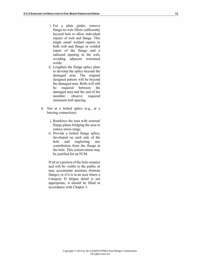
i. For a plate girder, remove flange-to-web fillets sufficiently beyond hole to allow individual repairs of web and flange. This might entail welded repairs to both web and flange or welded repair of the flange and a radiused opening in the web, avoiding adjacent restrained welds.
ii. Lengthen the flange splice plate to develop the splice beyond the damaged area. The original designed pattern will be beyond the damaged area. Bolts will still be required between the damaged area and the end of the member; observe required minimum bolt spacing.
b. Not at a bolted splice (e.g., at a
bracing connection):
i. Reinforce the area with external flange plates bridging the area to reduce stress range.
ii. Provide a bolted flange splice, developed on each side of the hole and neglecting any contribution from the flange at the hole. This conservatism may be justified for an FCM.
If all or a portion of the hole remains and will be visible to the public or may accumulate moisture (bottom flange), or if it is in an area where a Category D fatigue detail is not appropriate, it should be filled in accordance with Chapter 3.
12 G 2.2 GUIDELINES FOR RESOLUTION OF STEEL BRIDGE FABRICATION ERRORS
Figure 2.3-1—Hole Too Close to Face of Intersecting Plate
2.4—ELONGATED AND OVERSIZE HOLES C2.4
Error: A standard hole is improperly drilled, resulting in
an oversized, misshaped, or elongated hole.
Repair Recommendation: Standard and oversized holes are defined in the
AASHTO bridge design standards. In main members, investigate whether the connection can tolerate the reduced capacity of an oversized hole.
1. For most cases, where the oversize dimension
is not severe and is limited to a small portion of the holes at any location, it may be acceptable to leave the hole(s) “as is.” If many (or most) of the holes at a connection are oversized, evaluate whether the oversize
Avoid changing to specialty bolts and washers for only certain holes in a connection since the field bolting crew will have equipment calibrated for a specific size, and the wrong bolts could easily be installed. Acquiring different bolts may require testing and approval, significantly delaying field work. If necessary, ream or re-drill the hole as necessary and increase the bolt one size (e.g., ¾" to ⅞") at those locations, documenting locations with notes on the erection sheets, and marking the locations of the larger bolt(s) clearly for field personnel. Using this approach in the shop for individual bolt locations has a high potential for field installation errors and is not recommended.
G 2.2 GUIDELINES FOR RESOLUTION OF STEEL BRIDGE FABRICATION ERRORS 13
holes are structurally acceptable, and if so, consider drilling new splice plates to match with core-type bits (to avoid further enlarging existing holes), using the holes in the member as a template. (Reaming or drilling the existing splice plates can lead to alignment problems.) This will not increase design capacity, but will provide a better connection and may justify slightly exceeding overload limitations. A hardened washer or ply must cover any exposed non-standard hole, as required by the RCSC specification.
2. If there are a number of non-conforming holes at a single splice location and calculations indicate that the design bolts in oversize holes will not be structurally adequate, consider using larger diameter bolts if spacing and edge distances permit. If the problem is discovered in the field, larger bolts may be provided for just the oversize holes, but if found in the shop, larger bolts should be used for the whole pattern to avoid field confusion. The larger bolts may theoretically provide more strength than the original bolts, but need only meet plan requirements. If spacing will not permit the use of larger diameter bolts, higher strength bolts may be considered, but the same strength bolt should be used for the whole connection. Mixing ASTM A325 bolts in standard holes and A490 bolts in oversize holes within the same connection may require sophisticated review and result in jobsite confusion. Changing bolt size or strength will adversely affect field installation and must be closely coordinated with the erector and clearly noted on erection framing drawings.
3. If there is poor hole quality and inadequate edge distance, then that splice may need to be re-designed (e.g., lengthen the flange splice or add rows of bolts to a web splice), considering the effect of oversize holes on capacity. If the problems are concentrated in a transverse row of holes in a member adjacent to the splice centerline, another alternative may be removing the end portion of the member with the “problem” row. This may entail revising splice geometry based on
14 G 2.2 GUIDELINES FOR RESOLUTION OF STEEL BRIDGE FABRICATION ERRORS
“good holes” to be used, and may be possible if the opposite end of one spliced member hasn’t been cut to length or if end bearing locations can vary. This may be desirable to avoid eccentricity in a web splice. However, if connections for bearings, bracing, etc. have been installed, such extensive modifications may make the approach not viable.
4. Relocating the splice or removing and
replacing part of the member are last-choice options because of their complexity and potential for defects. Costs of additional material, increased erection labor, engineering to design and verify alternates, fabrication, and NDE should be the Contractor’s responsibility.
2.5—PARTIALLY DRILLED HOLES
C2.5
Error: A hole is partially drilled in the wrong location.
Repair Recommendation: Sometimes a hole is started into a main member
in a wrong location. The Engineer can determine if the section loss requires a welded repair or if grinding a smooth transition (1:10) in the direction of primary stress is sufficient. If the section must be restored by welding, grind and restore the base metal in accordance with Clause 3.2 of AASHTO/AWS D1.5M/D1.5 (and Clause 12 for FCM). See also Chapter 3.
In secondary members, if the hole penetrates less than ⅛" when a core-type bit is used, or ¼" when a bit with a center point is used, it may be fixed by feathering out at a 10:1 slope (see Figure 2.5-1). For deeper penetrations, treat as a mislocated hole per Sections 2.1, “Too Close to Adjacent Hole,” 2.2, “Hole Too Close to Free Edge,” and 2.3, “Hole Too Close to Face of Intersecting Plate.”
This repair approach is only valid for isolated, shallow, partial-depth holes. If there are several adjoining errors, the feathering approach cannot be used if it would interfere with the contact areas of adjacent bolts. If the hole is deeper and the situation permits, it may be preferable to drill the hole completely and fill it with a bolt.
However, this may affect the design and must be approved by the Engineer. Small, shallow repair welds may create greater problems than just leaving the hole-start alone, so they should be avoided if the only concern is cosmetic.
G 2.2 GUIDELINES FOR RESOLUTION OF STEEL BRIDGE FABRICATION ERRORS 15
As FixedAs Fabricated
DesignHole Location Centerline
AuxiliaryPlate
Partially Drilled
Hole
Stiffeneror
ConnectionPlate
TopFlange
BottomFlange
10:1Slope
Figure 2.5-1: Partially Drilled Hole
2.6—HOLES IN WEB FOR INTEGRAL ABUTMENT OF PIER REINFORCEMENT
C2.6
Error: Girders embedded at integral or semi-integral
abutments or made continuous by concrete encasement at piers have holes in the web to allow the passage of the reinforcing steel through the member. These holes may be mis-sized or mislocated, especially with skewed supports.
Repair Recommendation:
1. If the holes are too small to install reinforcement, enlarge them. This often must be done in the field, and since the area is not highly stressed and will be encased in concrete, holes may be enlarged by drilling, reaming, or thermal cutting (oxy-fuel or plasma) using a template.
2. If the holes are mislocated by one hole diameter or less, extend the holes towards their intended locations, making them slotted (see Figure 2.6-1). Hole-making methods listed in recommendation 1 may be used, but clear edge distances should be at least 1" [25 mm].
3. If the holes are mislocated by more than one hole diameter, then leave the holes “as is,” fill
A common problem is plans specifying a hole too small, because the following considerations were overlooked:
• the bar’s deformations extending outside its
nominal diameter, • the effects of skew and cross slope with
holes drilled perpendicular, or • physical limitations of threading heavy, long
bars through holes in successive beams.
The mislocation of a hole is not a significant problem as long as it permits correct placement of the reinforcement cage between beams and does not come too close to the face of the encasement.
If holes are enlarged in the field, shavings or resolidified metal should not be left near forms for exposed faces, and nearby epoxy-coated bars should be protected. Freehand thermal cutting (without a guide) is discouraged.
G 2.2 GUIDELINES FOR RESOLUTION OF STEEL BRIDGE FABRICATION ERRORS 17
CHAPTER 3
FILLING HOLES
Leaving bolt holes unfilled can reduce the fatigue
performance of the member, confuse erection personnel or subsequent bridge inspectors, and alarm the public. If holes are covered (e.g., by a diaphragm connection angle), there may be no need to fill the hole as long as fatigue provisions are met. If the hole will be exposed after erection but filling with a bolt would interfere with other items, and it is not readily visible to the public, confusing to the erector, or a fatigue concern, it may remain unfilled, but for a painted structure, the inside (perimeter) of the hole must be painted. A hole through one or more plies of a multi-ply joint that cannot be filled with a bolt may need to be sealed to prevent moisture entrapment and acceleration of main member deterioration due to rust.
3.1—BOLTED REPAIR OF ERRANT HOLES C3.1
Error: Bolt holes were drilled at the wrong location. Repair Recommendation: For primary and secondary members, fill the hole
with a high-strength, fully-tensioned bolt when adequate clearance exists. For unpainted weathering steel situations (e.g., ASTM A709/A709M or AASHTO M 270M/M 270 or Gr. 50W [345W] or Gr. HPS 70W [HPS 485W]), ASTM A325 Type 3 bolts can be used for all locations. For painted or metallized structures, bolt surface treatment should be similar to that specified for permanent bolts, but substituting hot-dip galvanizing for mechanical galvanizing should be permitted. Although the bolts should be fully tensioned in accordance with normal installation requirements, rotational capacity testing should not be required.
For standard holes, the bolt may be either 1/16" [2 mm] smaller than the hole with a washer under the turned element or 3/16" [5 mm] smaller than the hole with appropriate hardened washers under both the head and nut. (For slotted holes, see the RCSC specification.)
Filling holes with high-strength, fully-tensioned bolts may be considered an aesthetic problem, but it also provides the structural benefit of pre-compressing the edge of the extraneous hole to minimize fatigue crack initiation. The use of button-head twist-off bolts (ASTM F1852 or F2280) may improve the aesthetics.
See also Sections 3.2, “Welded Repair of Errant Holes,” and 3.3, “Correcting Weld-Restored Holes.”
18 G 2.2 GUIDELINES FOR RESOLUTION OF STEEL BRIDGE FABRICATION ERRORS
3.2—WELDED REPAIR OF ERRANT HOLES C3.2
Error: The repair of a mislocated hole may require that
the base metal be restored by welding when there is insufficient clearance to install a high-strength bolt or when other considerations such as stress conditions dictate.
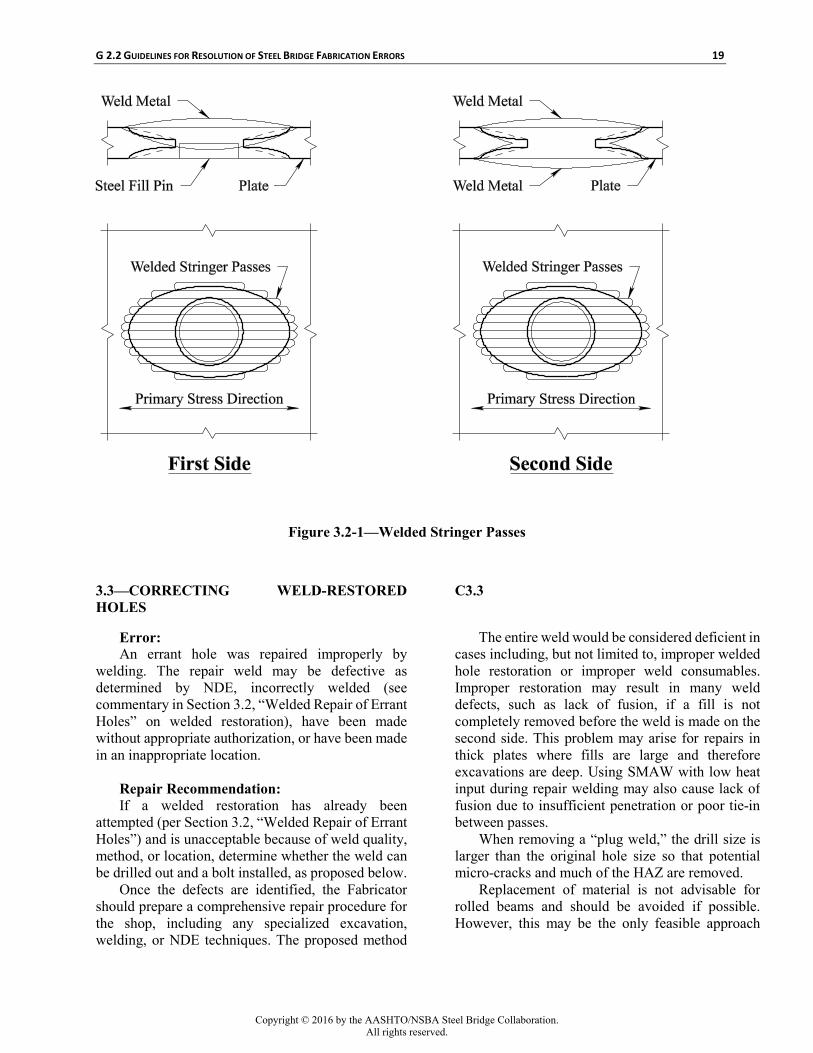
Repair Recommendation: See Figure 3.2-1. Insert a steel fill pin halfway
into the errant hole. Prepare the excavation into and out of the hole by grinding or gouging in an elliptical shape (long axis parallel to design stress if possible), and reweld with stringer passes along the length of the excavation. On the second side of the hole, grind or gouge out the fill pin to sound weld metal and contour the base metal and then weld with stringer passes as above. Grind both sides flush and UT or RT. (See Clause C-3.7.7 in AASHTO/AWS D1.5M/D1.5.)
The recommended weld repair procedure uses parallel stringer passes to avoid trapping slag or high residual stresses. Plug welding or spiral or circular weld passes are not to be used. Although removed during the second side weld, the steel fill pin should be similar to the material being repaired for equivalent weldability and chemistry. It can be a steel rod or even a punch-out, but its diameter should be within ⅛" [3 mm] (1/16" [2 mm] is preferred) of the hole size for weld continuity. The fill may be tacked inside the hole on the first side, since that tack will be subsequently consumed or removed, or on the second side in an area that will be removed while preparing that side. Gouging and grinding should provide a smooth transition into and out of the original hole so the weld can be continuous. Longitudinal slopes (parallel to primary stress) should be about 1:6 for shallow excavations (up to approximately ¼" [6 mm]), 1:4 from ¼" [6 mm] to ½" [12 mm] material, and 1:2 for over ½" [12 mm]. Transverse slopes (perpendicular to primary stress) can be steeper, about 1:1, if weld passes can be deposited with full fusion and not trap slag. Welds should continue onto the original surface before terminating, and the surface is ground to its required configuration after welding.
Although sometimes mistakenly referred to as “plug welding,” properly executed welded repairs of holes can restore the full section of the member. Plug welding is discouraged by AASHTO/AWS D1.5M/D1.5, and not permitted in tension or stress reversal areas. Plug welds usually start around the perimeter of the hole and spiral to the center, with either backing or another member behind the hole. The weld is made quickly so the adjacent weld more easily melts slag, but slag inclusions are common. The greatest problem is the weld shrinkage during solidification and cooling, generating extremely high residual stresses at the center of the plug, which is the last to solidify. This results in micro-cracks in the initial weld, coupled with near yield point residual stresses that may initiate cracking due to applied stresses on the structure that are far less than the predicted fatigue limit. Proper welded repairs of holes are NOT plug welds.
Welded repairs for high-stress situations or on thick material (over 2" [50 mm]) may require post-weld heating or thermal stress relief. Post-weld heating holds the material at an elevated temperature, allowing hydrogen to escape and reducing residual stress. This may be relatively low, such as 200 to 250°F [95 to 120°C] for 30 minutes in relatively thin material (e.g., up to 1" [25 mm]) or higher and longer for heavy or critical sections. Thermal stress relief involves higher temperatures for longer durations, as noted in Clause 12 of AASHTO/AWS D1.5M/D1.5, and requires sophisticated equipment and planning to avoid significant distortion. The Engineer and Fabricator should agree on this before initiating the repair, so that stress relief can immediately follow welding.
UT is the preferred method to assess full-thickness weld repairs, but MT may be used with the Engineer’s concurrence on thin material (up to ¼" [6 mm]), and RT may be required for FCM depending on the repair location and extent.
G 2.2 GUIDELINES FOR RESOLUTION OF STEEL BRIDGE FABRICATION ERRORS 19
Figure 3.2-1—Welded Stringer Passes
3.3—CORRECTING WELD-RESTORED HOLES
C3.3
Error: An errant hole was repaired improperly by
welding. The repair weld may be defective as determined by NDE, incorrectly welded (see commentary in Section 3.2, “Welded Repair of Errant Holes” on welded restoration), have been made without appropriate authorization, or have been made in an inappropriate location.
Repair Recommendation: If a welded restoration has already been
attempted (per Section 3.2, “Welded Repair of Errant Holes”) and is unacceptable because of weld quality, method, or location, determine whether the weld can be drilled out and a bolt installed, as proposed below.
Once the defects are identified, the Fabricator should prepare a comprehensive repair procedure for the shop, including any specialized excavation, welding, or NDE techniques. The proposed method
The entire weld would be considered deficient in cases including, but not limited to, improper welded hole restoration or improper weld consumables. Improper restoration may result in many weld defects, such as lack of fusion, if a fill is not completely removed before the weld is made on the second side. This problem may arise for repairs in thick plates where fills are large and therefore excavations are deep. Using SMAW with low heat input during repair welding may also cause lack of fusion due to insufficient penetration or poor tie-in between passes.
When removing a “plug weld,” the drill size is larger than the original hole size so that potential micro-cracks and much of the HAZ are removed.
Replacement of material is not advisable for rolled beams and should be avoided if possible. However, this may be the only feasible approach
20 G 2.2 GUIDELINES FOR RESOLUTION OF STEEL BRIDGE FABRICATION ERRORS
should be discussed with the Engineer’s representative before proceeding.
1. If welded restoration of the errant hole location is required but there are defects in the previous attempt, the defective portions of the earlier repair must be removed and a new welded repair must be made per Section 3.2, “Welded Repair of Errant Holes”). If defects are concentrated in the original hole, it may be removed by drilling a single hole. If they are more widespread (e.g., wrong consumables, base metal defect), excavation and drilling may both be needed. 2. If a hole was “plug welded,” and a bolt may be installed, drill out the entire weld and inspect the area. The drill bit must be slightly (⅛" [3 mm]) larger than and centered on the original hole’s location. A core bit is recommended because of disparities in the base and weld metal hardness. The remaining area should be inspected with MT. Install a high-strength bolt per Section 3.1, “Bolted Repair of Errant Holes.” Other options may be considered, including
removal and replacement of that portion of the member (see Chapter 6, “Web or Flange Replacement or Repair”), but their effect on the service life of the structure (including inspectability and maintenance) must be taken into account.
when multiple unacceptable weld restorations occur in one area.
3.4—COSMETIC REPAIR OF ERRANT HOLES USING STEEL PINS
C3.4
Error: A mislocated hole will be objectionably visible
in the final structure, or may cause confusion during erection, but installing a bolt is not practical and structurally restoring the hole is not required for strength or fatigue considerations.
Repair Recommendation: Fill the errant hole with a steel pin secured by
epoxy or other non-stress-concentrating methods. Then grind flush.
Welding the steel pin in place is NOT RECOMMENDED. Welding a plug into the hole is unacceptable from a fatigue standpoint. Installing a pin with very small welds may result in high residual stresses and defects that could initiate cracking in otherwise lightly loaded members. Web and bracing members are seldom more than ½" [12 mm] thick, so the AASHTO/AWS D1.5M/D1.5 ¼" [6 mm] minimum weld size from both sides would result in a full welded repair. Brazing may also be considered. The pin should be approximately 1/16" [2 mm] smaller than the hole diameter and of a compatible material. For exposed, unpainted steel, an ASTM A588 round bar may be used for areas visible to the public, and either A588 or other corrosion-resistant material (e.g., stainless steel) may be used elsewhere.
G 2.2 GUIDELINES FOR RESOLUTION OF STEEL BRIDGE FABRICATION ERRORS 21
3.5—COSMETIC REPAIR OF ERRANT HOLES USING MOLTEN ZINC
C3.5
Error: A mislocated hole will be objectionably visible
in the final structure, or may cause confusion during erection, but installing a bolt is not practical and structurally restoring the hole is not required for strength or fatigue considerations.
Repair Recommendation: If the Owner permits, a plug of molten zinc may
be used instead of the steel pin in Section 3.4, “Cosmetic Repair of Errant Holes Using Steel Pins.” This may be preferred since there will be no question about the type or setting time for epoxy, or qualifications required for brazing. The zinc will also provide corrosion protection.
The first step is to make 45° chamfers, ⅛" [3 mm] deep into the plate on each side (see Figure 3.5-1). Then clean and coat the inside of the hole with a zinc-rich primer or a flux that will permit adhesion. Next, preheat the member and backing to 200° F [95° C] and fill the hole with molten zinc. Finally, remove the backing plate, grind flush, and clean and coat the area.
This repair approach may not be aesthetically appropriate for errant holes in weathering steel that will be highly visible to the public. Filling a hole with molten zinc is a viable fix for some owners. This type of repair is especially effective when a plate partially covers the errant hole, as it will seal the joint against water.
After painting, it is difficult to tell where the misdrilled hole was. Also, grinding and blast-cleaning are unlikely to dislodge the plug.
22 G 2.2 GUIDELINES FOR RESOLUTION OF STEEL BRIDGE FABRICATION ERRORS
CHAPTER 4
STIFFENERS AND CONNECTION PLATES
Stiffeners and connection plates have different structural purposes, but the same plate can fulfill both functions. Differing design requirements create possibilities for errors.
AASHTO requires that cross-frame and diaphragm connection plates welded to the web be positively connected to both flanges, preventing fatigue induced by out-of-plane distortion.
Transverse intermediate stiffeners not used as connection plates are either placed in pairs on opposite sides of the web and tight fit to the compression flange, or used singly and positively connected to the compression flange, but do not need to contact or connect to the tension flange in either case.
Common types of errors related to stiffeners or connection plates are improper flange attachment, mislocation, and incorrect hole placement. Repairs depend on the error and whether a stiffener or a connection plate is involved. The stage of fabrication may also affect repairs.
4.1—ERRONEOUS WELD C4.1
Error: A connection plate or stiffener is welded to a
flange where welding is not specified. Repair Recommendation: If a connection plate or stiffener is welded to the
tension flange instead of the compression flange, evaluate the location’s stress range and, if acceptable for fatigue category C', consider leaving the tension flange welds and, if a connection plate, welding to the compression flange as well. MT the tension flange welds 100 percent.
Depending on the situation, the weld may need to be removed and, if called for on the shop drawings, a bolted connection to the tension flange installed.
If fatigue stresses at the connection plate- or stiffener-to-tension flange weld exceed the allowable, check the calculated range at the closest portion of the
If the welds are good quality and the fatigue range is below the limit for Category C', the Owner should consider allowing the errant weld to remain. This avoids potential problems caused by removing a weld, which still may leave some weld effects at the flange surface.
Welds to the tension flange may be prohibited by Owner policy or because of fatigue stresses exceeding those permitted for Category C' (flange-to-web welds are Category B; stiffener or connection plate welds to flanges and webs are Category C'). If steel with a yield strength of 100 ksi [690 MPa] is present, perform hardness testing to ensure sufficient removal, so any remaining weld HAZ has approximately the same hardness as the adjacent base metal surface. Brinell, Rockwell, or Vickers hardness testing may be used.
G 2.2 GUIDELINES FOR RESOLUTION OF STEEL BRIDGE FABRICATION ERRORS 23
connection plate- or stiffener-to-web weld to verify what portion of it, if any, also exceeds the category C' limit. Fillet welds must be removed from areas where stress range is excessive, and this may be done by carefully removing the welds from those areas without significantly damaging the flange or web, or by removing the entire plate in accordance with Section 4.10, “Plate Removal.” AASHTO does not permit a higher stress range category if a complete joint penetration weld replaces the fillet, so that is not an option.
To remove a fillet weld without removing the stiffener or connection plate, the stiffener or connection plate may be thermally cut near the weld before weld removal, in accordance with Repair Recommendations in Section 4.10, “Plate Removal,” taking care not to damage the web or flange. The cut may go full length of the weld at a flange connection, but for a web connection, fatigue performance can be improved by pre-drilling a hole in the stiffener or connection plate at the point where the fatigue stress range no longer exceeds the category C' allowable. Use a core-type bit to produce a hole approximately tangent to the web (but without damaging the web), then terminate the cut at this hole. Pre-cutting simplifies removal of the weld or preparation for a bolted tab plate connection to the flange. See Figure 4.1-1.
Welds joining stiffeners or connection plates to the web are often made with an automatic, opposed head machine, welding both sides simultaneously. For plates up to ½" thick, this often effectively produces a complete joint penetration condition, further impeding removal and increasing the risk of damage to the web. Removal of such welds should be avoided if calculated stress ranges only slightly exceed those permitted for Category C'.
24 G 2.2 GUIDELINES FOR RESOLUTION OF STEEL BRIDGE FABRICATION ERRORS
Limited arc-gouging and careful grinding must be
aligned so that any base metal damage occurs in the stiffener or connection plate, not in the web or flange. Gouging should employ a guide or automated equipment to ensure linear motion stopping before the web-flange juncture, and the gouged groove must stay outside the flange or web. Grinding must also be controlled to avoid overheating permanent material. After welds are removed to the face of the stiffener or connection plate, a small grinder should be employed to sever the weld throats. The fragment of stiffener or connection plate is removed and the adjacent face of the flange or web is ground smooth as needed. Grind previous weld locations to slightly (1/16" [2 mm]) below the surface plane to remove part of the fusion zone and any accompanying weld anomalies. The surface is then 100 percent MT inspected. The cut edges of the stiffener or connection plate are also ground to remove significant irregularities, resolidified material, etc. and all surfaces are prepared and painted as required.
If a bolted angle connection to the tension flange is required, the face of the connection plate must be ground, cleaned, and primed as required by the contract before angles are installed.
If the connection plate is welded to a tab plate bolted to the flange, the contact face of the flange and tab plate are prepared and primed if appropriate, and the edge of the connection plate is cut, ground, and prepared for welding to the tab plate. The tab plate is then inserted, bolted, welded, cleaned, and painted per contract requirements.
4.2—MISLOCATED PLATE TACKED IN PLACE
C4.2
Error: A stiffener or connection plate has been tack-
welded at the wrong location. Repair Recommendation: If an error is noticed before the plate has been
completely welded, remove the plate, either by removing individual welds (see Section 4.1, “Erroneous Weld”) or by destroying the plate and removing the welds (see Section 4.10, “Plate Removal”) and replacing it in the correct location. Completely remove the tack welds and take the plate out of the assembly. Grind welds out approximately 1/16" [2 mm] below the base metal surface, and MT each removal area. If the base metal has a specified
The tack welds must be completely removed because they typically do not meet quality standards for permanent welds. The HAZ properties in tack welds are poorer than production welds because of poor shielding and rapid cooling and solidification. Other defects commonly associated with tack welds include arc strikes (see Section 7.5, “Arc Strikes”), inclusions, lack of fusion, and undercut.
When removing tack welds, grinding is preferable to gouging. Grinding avoids both excessive removal of material and high heat input. Small die grinders are used for final finishing and severing of the weld at the root. The majority of the weld must be severed by grinding. Do not try to break tacks by prying plates apart since cracks may
G 2.2 GUIDELINES FOR RESOLUTION OF STEEL BRIDGE FABRICATION ERRORS 25
minimum yield strength of 100 ksi [690 MPa], perform hardness testing to ensure sufficient removal, so the remaining weld area HAZ has approximately the same hardness as the adjacent base metal surface. Brinell, Rockwell, or Vickers hardness testing may be used.
initiate in the base metal or portions of base metal may be pulled out.
4.3—MISLOCATED INTERMEDIATE STIFFENERS
C4.3
Error: An intermediate stiffener is installed at the wrong
location.
Repair Recommendation: If the mislocated stiffener does not interfere with
any other members or attachments and its welds do not violate fatigue stress limits (see Section 4.1, “Erroneous Weld”), leave it in place. If allowed to remain, determine whether it is close enough to the specified position to provide the intended bracing effect. Otherwise, install a stiffener at the correct position.
If the stiffener at the present location interferes with other members or attachments, partially or completely remove the stiffener (see Section 4.10, “Plate Removal”) to provide necessary clearance without damaging the member. Partial removal may entail cutting away some of the outstanding portion while leaving the weld intact, but small fragments which might be stress concentrators or maintenance problems should not remain. 4.4—MISALIGNED BEARING STIFFENERS
Misplaced intermediate stiffeners usually do not present structural problems if only welded to the compression flange and web. Leaving all or most of the stiffener in place is preferred to removing the welds, especially those on the web (see Section 4.1, “Erroneous Weld,” Commentary).
If the Fabricator believes the mislocated stiffener is sufficiently close to the plan location that it will adequately brace the web without also installing a stiffener at the correct location, then preliminary calculations should be submitted to the Engineer for review. The Owner’s designer may compare the actual stiffener location with original calculations and code requirements to determine if the installed stiffener is sufficient.
C4.4
Error: A bearing stiffener is misaligned beyond the
tolerances described in AASHTO/AWS D1.5M/D1.5 Clause 3.5, but the bearing end is within the middle 50 percent of the bearing-to-flange contact area. This may include being out of plumb, not normal to the flange, or not perpendicular to the web.
Repair Recommendation: Determine the location and condition of the
bottom, bearing end of the stiffener and the overall alignment. If the bottom of the bearing stiffener is within the middle 50 percent of the sole (top) plate of the bearing (see Figure 4.4-1A), the finished end is in direct contact with the flange, the lateral misalignment (skew to the web) is within 15° of
The primary role of the bearing stiffeners is to act with a portion of the web and form a column to transfer gravity-induced forces through the sole plate. Therefore, the location of the bottom of the bearing stiffener with respect to the sole plate is more important than the location of the top of the bearing stiffener.
Exact vertical alignment is not critical to the capacity of the web-stiffener column, so bearing stiffeners typically may be either plumb (i.e., truly vertical) or normal to the bottom flange, even for structures on profile grades of 10 percent. Misalignments up to 5 percent of member depth should not significantly affect total vertical load carrying capacity.
26 G 2.2 GUIDELINES FOR RESOLUTION OF STEEL BRIDGE FABRICATION ERRORS
specified, and the vertical misalignment is less than 5 percent of the member depth, then consider leaving the bearing stiffener “as is.” If lateral misalignment creates angles of intersection outside the range of fillet welds (see AASHTO/AWS D1.5M/D1.5 Fig. 2.3), appropriate approved weld procedures must be employed. If the connection of other elements, such as bolt-on bearings, diaphragms, or cross-frames, is affected, the vertical and lateral misalignment must still permit a positive connection by the use of shims, modified elements, or other means.
Regardless of other factors, if the finish-to-bear end of the stiffener does not satisfy the flange contact requirements of AASHTO/AWS D1.5M/D1.5 Clause 3.5.1.9, either remove and replace the stiffener or provide a CJP weld between the stiffener and flange.
If the bottom location of the bearing stiffener is within the middle 50 percent of the sole plate-to-flange contact area but its vertical misalignment is greater than 5 percent of its height, determine if connections can still be completed. If so, then leave the stiffener “as is” and add a stiffener of the same cross section as close as practical to the specified bearing point (see Figure 4.4-1B). If the stiffener on the far side of the web is properly located and the inclined stiffener prevents installing an additional full-depth stiffener, a partial-depth stiffener along with the misaligned stiffener may adequately convey gravity loads to the bearing (see Figure 4.4-1C). If connections cannot be made, remove and replace the bearing stiffener (see Section 4.10, “Plate Removal”).
If the bottom of the bearing stiffener is completely outside the middle 50 percent of the sole plate-to-flange contact area, see Section 4.5, “Mislocated Bearing Stiffeners.”
Weld removal may be detrimental to remaining material and should be avoided if either the existing condition or adding other stiffeners will provide adequate capacity. If finished-to-bear (milled or ground) ends of stiffeners do not satisfy contact requirements, CJP welds effectively provide 100 percent bearing on the flange, but such welds are difficult and expensive, so they should not be specified on contract plans.
G 2.2 GUIDELINES FOR RESOLUTION OF STEEL BRIDGE FABRICATION ERRORS 27
Figure 4.4-1—Misaligned Bearing Stiffener
4.5—MISLOCATED BEARING STIFFENERS C4.5
Error: A bearing stiffener is placed at the wrong
location, outside the middle 50 percent of the bearing-to-flange contact area.
Leaving the stiffener in place poses less risk to the member than removal, which may damage the web or flanges. If a diaphragm or cross-frame is to be attached to a mislocated or added bearing stiffener, a viable connection scheme must be submitted.
28 G 2.2 GUIDELINES FOR RESOLUTION OF STEEL BRIDGE FABRICATION ERRORS
Repair Recommendation:
1. If the location varies from the design plans or approved shop drawings by a sufficient distance to allow welding (usually 8" [200 mm]) and completion of any connections, then leave the stiffener in place, fill any holes with bolts (see Section 3.1, “Bolted Repair of Errant Holes”), and add a new stiffener at the specified location.
2. Bearing stiffeners mislocated outside the middle 50 percent of the flange-to-bearing contact area but by less than about 8" [200 mm]) may not provide adequate clearance to weld a stiffener at the proper location. In this case, determine if a stiffener of the specified size can be added within the middle 50 percent of the flange-to-bearing contact area (see Figure 4.4-1B). The mislocated stiffener plus the added stiffener may provide adequate vertical load capacity, but calculations verifying this may be required by the Owner.
3. If neither of the above approaches is acceptable, the stiffener must be removed in a way that minimizes damage to the girder. If welds are large, sacrifice the mislocated stiffener to avoid excavating the web or flange. Follow the guidelines for removal per Section 4.10, “Plate Removal.”
4.6—MISLOCATED CONNECTION PLATES C4.6
Error: A connection plate is fit at the wrong location. Repair Recommendation: 1. When a connection plate is misplaced enough to permit welding at the specified location, the preferred solution is to leave the plate in place, fill any holes with bolts (see Section 3.1, “Bolted Repair of Errant Holes”), and add a new connection plate at the proper location. This solution also depends on the lack of interference with other elements and access for subsequent fabrication and erection. 2. Even small location errors may be unacceptable in situations such as a tightly curved structure, where the design depends upon bracing interaction to resist the horizontal forces due to
When unique diaphragms or crossframes are made for misaligned stiffeners, adequate piece marking is essential to avoid erection difficulties. If a stiffener is skewed incorrectly, a bent plate may be used to adapt the fit.
Where connection plates carry design loads, such as braces providing frame action in tightly curved structures or transverse members supporting terminating girders, modifications to connections and locations may have significant effects on structural behavior, so reanalysis would be needed.
G 2.2 GUIDELINES FOR RESOLUTION OF STEEL BRIDGE FABRICATION ERRORS 29
curvature. In these situations, the errant connection plate must be removed without damaging the girder. Follow the guidelines in Section 4.10, “Plate Removal.”
4. When connection plates are mislocated but prevent welding another plate at the specified location, the “as fabricated” condition may be structurally acceptable if bent gusset plates, fill plates, or other bracing modifications are acceptable. The gusset plates should be in full contact with the connection plates before final tightening of bolts.
4.7—MISLOCATED HOLE IN A CONNECTION PLATE OR BEARING STIFFENER
C4.7
Error: A hole is incorrectly located in a connection plate
or bearing stiffener. Repair Recommendation: When holes are mislocated in a connection plate
or a bearing stiffener, several options exist:
1. If the item has not been fit (tacked or welded) to the girder, the piece can be replaced.
2. If the item is already attached to the member, fill the hole with a bolt unless the bolt conflicts with other elements, and then either leave the hole open or fill. See Section 3.1, “Bolted Repair of Errant Holes,” Section 3.2, “Welded Repair of Errant Holes,” or Section 3.4, “Cosmetic Repair of Errant Holes Using Steel Pins.”
3. If the item is attached to the girder, additional
holes can be drilled if the errant holes do not interfere or else a new gusset plate, cross-frame, or diaphragm can be fabricated to match holes already drilled in the plate.
4. If the mislocated holes are close to their specified
locations, verify if slotting is acceptable based on the loading and number of mislocated holes. If so, slot the holes and provide plate washers and appropriate length bolts, with notification to the erector.
Similar errors include installing a plate with the wrong piece mark or upside down.
Investigate whether holes may be slotted vertically or horizontally, depending on anticipated loads, in the plate or in the connecting element. Slots may not be acceptable if cross-frames or diaphragms carry design loads, such as in a curved structure, so the Owner’s acceptance is necessary before adding slots or oversize holes not shown on the contract plans. Slots may be considered in both elements, or in one with the other having standard holes. Slots under the bolt head or nut must be completely covered by either individual plate washers or common bars with multiple holes. The RCSC specification defines washer requirements.
If a custom diaphragm or cross-frame is fabricated to fit in this location, the shop drawings’ detail sheet and erection (E) sheets are revised to reflect the “as fabricated” condition, where it is to be located, and the field bolt and washer requirements.
30 G 2.2 GUIDELINES FOR RESOLUTION OF STEEL BRIDGE FABRICATION ERRORS
5. If none of these options are acceptable and the
plate must be removed, follow the procedure in Section 4.10, “Plate Removal.”
4.8—INCORRECT FIT OF CONNECTION PLATE OR STIFFENER TO FLANGE
C4.8
Error: An installed stiffener or connection plate does not
provide the specified fit to the flange. Repair Recommendation: The recommended repair varies depending on
whether an intermediate stiffener, a connection plate, or a bearing stiffener is involved. If the stiffener is only tacked, remove and replace correctly. See Section 4.2, “Mislocated Plate Tacked in Plate.”
Intermediate stiffener: If a single stiffener is welded to the web but is too
far from the compression flange for the AASHTO/AWS D1.5M/D1.5 allowable fillet weld fitup gap, extend it with a fill plate between the stiffener and flange. For gaps of 3/16" to ¼" [5 to 6 mm], insert a bar the width of the stiffener and enlarge the fillet leg size accordingly (see Figure 4.8-1B). For gaps over ¼" [6 mm] up to 1" [25 mm], insert a tab plate and weld the stiffener to the tab and the tab to the flange with separate welds (see Figure 4.8-1C).
Intermediate stiffeners placed in pairs on both sides of the web are usually tight fit to the compression flange but not welded. After welding to the web, if one of a pair is short, the other can be welded to the compression flange, unless the area is subject to stress reversal under live load. If reversal may lead to tension in both flanges and the stress range exceeds fatigue category C' allowable, then extend both stiffeners by lap-splicing plates per the preceding paragraph, but do not weld to the flange.
Connection plate: If the contract requires a bolted connection at the
tension flange, and tab plates are specified, the tab thickness may be increased or a fill may be added between the tab and flange. If an angle connection is shown, a small increase (approximately the angle leg thickness) in the height of gap between the angles
Force fitting stiffeners or connection plates must be avoided, as this can result in bowing the installed plate, high residual stresses, and flange or web distortion.
G 2.2 GUIDELINES FOR RESOLUTION OF STEEL BRIDGE FABRICATION ERRORS 31
may be permitted, but a larger increase may lose connection rigidity or not leave room for bolts.
For connection plates to be welded, see preceding measures for welded intermediate stiffeners.
Bearing stiffeners: Bearing stiffeners at the non-load transfer end
(usually the top flange) are treated as described above for connection plates and intermediate stiffeners.
If the bearing stiffener is only tacked, consider removing it, preparing the finish-to-bear end by building up with weld if necessary, grinding or milling to proper geometry, and reinstalling.
If a “finish to bear” (“grind to bear,” “mill to
bear”) fit is specified and the stiffener is to be welded to the web, but the fitup criteria of Clause 3.5.1.9 in AASHTO/AWS D1.5M/D1.5 are not met:
1. For gaps from 1/16" to 3/16" [2 mm to 5 mm],
consider drive-fitting a machined fill the width of the stiffener to be covered by the appropriate size fillet weld (increased as required by AASHTO/AWS D1.5M/D1.5 for fitup gaps). See Figure 4.8-1B.
2. If the stiffener–flange gap is over 3/16" [5 mm], consider trimming and preparing the stiffener so a machined fill may be prepared to drive fit and extend approximately ⅜" [10 mm] beyond each face of the stiffener, allowing individual 5/16" [8 mm] fillets to join the stiffener, fill, and flange. See Figure 4.8-1C.
3. For gaps less than 1/16" [2 mm] (e.g., contact along
one edge), either the stiffener may be trimmed to permit inserting a machined fill, or the joint may have a CJP weld.
Both approaches have potential advantages and
shortcomings. Depending on the initial geometry of the gap, achieving a high-quality CJP weld may be problematic since terminations near the flange-to-web juncture have poor access for preparation and welding. Additionally, CJP welds may induce unacceptable distortion in thinner flanges. Trimming the end of the stiffener and achieving a finish-to-bear surface within the resulting small gap is also very difficult, but the final condition may impose lower residual stresses than a CJP weld. Therefore, at abutments where flange stresses are low and welding
32 G 2.2 GUIDELINES FOR RESOLUTION OF STEEL BRIDGE FABRICATION ERRORS
access is better, the CJP weld may be preferred, but at continuous piers, the machined fill may be more viable. The situation is typically at a compression flange, so unless the Owner has a specific concern, the Fabricator should be allowed either option.
Figure 4.8-1—Stiffener or Connection Plate Fit Repair Examples
4.9—MISPLACED PLATE ON EXTERIOR BEAM FACE
C4.9
Error: A transverse stiffener or connection plate is
erroneously installed on the outside face of an exterior girder.
If a stiffener is located on the wrong face of a girder, it will still function as intended and does not need to be relocated unless this is necessary for aesthetic or clearance reasons. A connection plate on the outside face of a girder may be allowed to remain if conditions permit, but another must be added on the correct side.
The recommendations for intermediate stiffeners do not address gaps over 1". Repairs other than removal and replacement, such as extension
G 2.2 GUIDELINES FOR RESOLUTION OF STEEL BRIDGE FABRICATION ERRORS 33
Repair Recommendation:
1. For areas where aesthetics are not significantly affected, leaving the element in place avoids potential damage from removal operations, as long as fatigue conditions are satisfied. Unused holes may be filled with bolts per Section 4.7, “Mislocated Hole in a Connection Plate or Bearing Stiffener.”
2. If the plate must be removed for appearance or to avoid interference with other items, follow the removal procedure in Section 4.10, “Plate Removal.”
plates, are possible, but this situation probably indicates a larger problem.
4.10—PLATE REMOVAL C4.10
Error: It has been determined that a stiffener or
connection plate must be removed. Repair Recommendation: Remove the plate using one or more of the
following:
1. Thermal-cut through the stiffener as close to the web or flange as possible without gouging the girder. Remove the remaining material by grinding or machining.
2. Remove most of the welds or cut the stiffener using air-carbon arc gouging, avoiding any damage to the web or flange.
3. Grind through the throat of the fillet welds—
either entirely or that remaining after gouging. 4. Grind or machine the fillet weld remnants smooth
and flush with the surrounding base metal. Final grinding should be parallel to the direction of primary applied stress (typically longitudinal on webs and flanges).
100 percent MT the weld removal areas.
Removal of plates may be required for a variety of reasons. However, leaving the plate in place is often a better solution to avoid the risk of damaging the girder. See the commentary in Section 4.2, “Mislocated Plate Tacked in Place,” regarding removal of welds. Cutting thick plates by arc gouging is difficult to control, removes more material, and applies more heat to surrounding material than thermal cutting methods (e.g., oxy-gas or plasma). Grinding through welds is less likely to damage adjacent material, but is slower than cutting or gouging. Grinding with high pressure can bring material to melting temperatures, so prolonged grinding may impart more heat than rapid thermal cutting or gouging. Grinding alone to remove large amounts of material (weld and plate) is not efficient, so if thermal cutting leaves significant material, machining (horizontal mill, etc.) may be more productive.
Special angled oxy-fuel cutting heads are available for cutting close to surfaces. Plasma heads and conventional oxy-fuel heads cannot get within about ½" [12 mm] of the surface while cutting parallel to it, and cutting diagonally toward the surface will damage the base metal.
34 G 2.2 GUIDELINES FOR RESOLUTION OF STEEL BRIDGE FABRICATION ERRORS
CHAPTER 5
MISCUT MEMBERS
5.1—PLATES C5.1
Error: A plate is cut incorrectly. Repair Recommendation: In order of preference:
1. Investigate whether the plate can be used as is in the designed location or in a different location. Refer to the contract plans, shop drawings, and material cutting sheets to study this alternative, including minor changes in bolt spacing.
2. If discovered early enough, cut an adjacent plate to compensate for the difference in length (similar to Section 5.2, “Entire Girder Cut Short”).
3. Splice on new material by butt-welding to
achieve the proper length.
NDE requirements for a butt-welded splice per AASHTO/AWS D1.5M/D1.5 apply. Note that CJP butt welds (with the weld reinforcement ground flush) have the same fatigue category (B) as flange-to-web fillets, so the permitted stress range for plate girders will not change. Butt welds should be located at least 6" [150 mm] from other transverse welds (e.g., web or flange butts, fillets on stiffeners or connection plates, etc.). The added material should be long enough to control distortion during welding, so 3' (1 m) is a desired minimum, even if most will subsequently be removed.
5.2—ENTIRE GIRDER CUT SHORT C5.2
Error: During burn-off for length, the girder was cut
shorter than the specified length. Repair Recommendation:
1. First, determine if other girders in the same line have sufficient additional length to compensate for the miscut piece. Relocation of a field splice up to a few feet [approximately 1 m] may not be structurally significant for most girders, but bearing stiffeners and connection plates may require relocation and final splice locations must clear cross-bracing connections. If other segments cannot satisfactorily compensate, then either the miscut section or another segment must be lengthened or replaced.
2. If the miscut member must be lengthened, (a) the webs and flanges may be either completely or
The repair depends on the member type and structural behavior required at that location. Usually, a butt-welded repair is suitable. However, an additional bolted splice (i.e., an extra splice within a member specified as a single member) may be acceptable to the Engineer and more practical for the shop, based on the situation. Small shops fabricating W-beam structures may not have the expertise, equipment or qualified procedures to make CJP welds that would satisfy AASHTO/AWS D1.5M/D1.5 or the Engineer.
Added bolted splices must be designed for the location in question; a splice design from another location cannot simply be transferred to the repair location. AASHTO requires bolted splices to be based on both the properties of the sections joined and also the maximum stresses at the splice location. If heavier material is spliced to lighter (i.e., thinner or narrower) material to extend a flange, or if the
G 2.2 GUIDELINES FOR RESOLUTION OF STEEL BRIDGE FABRICATION ERRORS 35
partially disconnected and new material welded on, or (b) an additional segment may be added with a bolted splice. For a relatively short girder, completely removing flange-to-web welds simplifies butt-welding extensions and permits the flange and web extensions to be located at opposite ends of the piece. For longer girders, partial removal of the flange-to-web welds is required to allow separation while welding flange and web extensions and expedites reassembly of the web and flanges. Reattaching the miscut segment using a bolted splice might be employed if a substantial portion of the girder is erroneously removed. This could be shop-bolted and avoids removing finished welds, but the splice will typically be designed by the Contractor’s engineer and submitted for the Owner’s approval, so delays and engineering costs may outweigh any benefits.
3. For partial removal of flange-to-web welds to add
material, arc-gouge the fillet welds well beyond the area of the welded butt splices. The flanges must be pulled far enough from the end of the web to permit joint preparation and welding, without kinking or permanently deforming the flange. Weld removal limits should be based on flange thickness, but it will usually be at least 6' [2 m] (see Figure 5.2-1). Either the flanges or web must be cut to provide at least 6" [150 mm] of offset between adjacent butt welds. Typically the web is left long to allow clearance for run-off tabs. Flanges usually have their inside face welded first so backgouging is uninterrupted on the outside face. The added sections of the newly fabricated web and flange sections should be a minimum of 3' [1 m] in length in order to control distortion during welding, even if portions of this are subsequently removed. Butt welds must be ground flush per AASHTO/AWS D1.5M/D1.5 Clause 3.6.3, as required, and then NDE of each is performed per governing specifications prior to rejoining the web and flanges. Remove temporary braces and bring the flanges and web into the required alignment. After aligning and tacking components, but prior to welding the flanges to the web, remove an additional 2" [50 mm] of flange-to-web weld at the “Point of Attachment” labeled in Figure 5.2-1 and MT 12" [300 mm] of fillet beyond the removal to ensure that any
bolted-splice location is some distance from an existing splice, the design requirements may change.
For a rolled beam or for a girder primarily loaded in shear, access holes may be allowed without separating the web and flanges or staggering the butt welds. A butt splice with access holes is often more suitable near end supports and when the length to be replaced is relatively small, especially if it will be near an existing bolted splice. If weld access holes need to be filled for cosmetic or moisture reasons, use a non-structural dimensionally stable filler (e.g., auto-body filler) suitable for painting and long-term exterior exposure, bolted covers, or other non-structural methods, but do not fill them with weld. See Section 3.2, “Welded Repair of Errant Holes,” and Section 3.3, “Correcting Weld-Restored Holes,” for discussion of problems associated with unnecessary welds.
36 G 2.2 GUIDELINES FOR RESOLUTION OF STEEL BRIDGE FABRICATION ERRORS
cracks are eliminated. Weld the flanges to the web and MT fillet welds 100 percent. Verify the dimensions and then trim the girder to the correct length.
3' (1 m) minimum
6' (2 m) minimum
2" (50 mm)
Point ofAttachment
StaggeredButt-Welds
Fillet Weld
Fillet Weld
6" (150 mm) minimum
Figure 5.2-1—Staggered Butt Weld Repair to Extend Length
4. Consider adding a complete section to the cut end if a rolled beam was cut short and must be weld-spliced (i.e., a bolted splice is not a viable alternative) or if a plate girder near a simple support (within 10 percent of the span length) and primarily carrying shear with low moment-induced stresses is miscut. See Figure 5.2-2. Make weld joint preparations on flanges and webs and cut weld access holes per applicable Figure 5.2 details in the AWS D1.1 Structural Welding Code—Steel (also see Figures 7.1 and 7.2 in SBC S2.1). The fatigue stress range limit in the AASHTO LRFD Bridge Design Specifications must be satisfied. Access holes are not to be closed by welding, but may be covered for aesthetic reasons if directed by the Owner. After all butt welds are completed, NDE each per governing specifications. For plate girders, wrap the ends of flange-to-web fillet welds at the access holes and grind smooth to required access hole configuration after the butt welds are complete. Inspect butt joints by 100 percent UT and fillet welds on permanent portion of extension by 100 percent MT, verify dimensions, and trim to the correct length.
Error: The web is cut short at one or both flanges and
already welded to flange(s). Repair Recommendation:
1. The entire member can be cut to “match” the error, if an adjacent connecting member can be lengthened to compensate for the error.
2. If error is small (up to about 1" [25 mm]) and bracing and bearing connection holes have already been made, consider shifting the member (or both members at a splice) to compensate, maintaining splice gaps but offsetting one or more bearing and bracing connection locations. The Engineer must verify whether bracing connections and bearings can deviate without erection or serviceability problems and approve the modifications.
3. If the miscut web is at a simply supported end
(e.g., an abutment):
When trimming girders to length with the web horizontal, the web may be cut before the flanges due to the weight of the flanges and low transverse strength of the web. The cut may be normal to the flanges or skewed slightly if the girder slope changes at the splice.
The option of shifting the bearing position or moving the girder line requires evaluating the effects on other bearing locations, alignment of cross-bracing members, the effects on modular or finger-type joints, and other ramifications of such changes.
38 G 2.2 GUIDELINES FOR RESOLUTION OF STEEL BRIDGE FABRICATION ERRORS
a. If it is an integral abutment or pier, or if the
web is cut correctly at the bottom flange but shorter above that (Figure 5.3-1A), consider leaving it “as is.”
b. If the web is cut short at the bottom flange, but in full contact with the bearing plate and proper positioning of the bearing stiffeners is possible (Figure 5.3-1B), it should be considered for acceptance based on the required stiffener web column capacity.
c. If the web is cut so short at the bottom flange that the bearing will not have full contact or the stiffener web column will be deficient (Figure 5.3-1C), consider either shifting the bearing position on the seat or moving the entire girder line slightly toward that support. See Section 4.5, “Mislocated Bearing Stiffeners,” for distances that this approach can accommodate. Assembly with items such as end frames must be resolved.
4. If the above alternatives are not viable, a butt-welded section will need to be added to correct the error (see Section 5.2, “Entire Girder Cut Short”).
40 G 2.2 GUIDELINES FOR RESOLUTION OF STEEL BRIDGE FABRICATION ERRORS
5.4—FLANGE TRANSITIONS C5.4
Error: A flange thickness or width transition is
fabricated at the wrong location. Repair Recommendation:
1. If a thicker or wider plate exceeds the length specified and will not cause interference or significantly affect structural behavior, leave “as is” because the beam section provides greater capacity than required. If it interferes with a bolted connection to the thinner plate and the bolted connection cannot be relocated slightly, a beveled fill may be used to square up the connection or the thicker plate may be ground to match the thinner plate (see Figure 5.4-1).
2. If a thicker or wider plate extends far beyond its intended termination, the girder’s structural properties and behavior change. Redistribution of loads and changes in deflection may not be acceptable. If heavier material extends more than a few percent of the span length beyond plan dimensions, the effects on the overall structure must be calculated.
Document the structural effects of the error to see if the flange can be left “as is.” For small errors of 1 percent to 2 percent of the span length, formal calculations may not be required.
The actual yield stress and ultimate strength of the flange material may also be documented based on MTRs. While mechanical properties vary within a plate, the MTRs give an indication of representative properties. Yield stresses are commonly 10 percent to 15 percent higher than the minimums required, especially for 36 ksi [250 MPa] material, so this may provide some justification for allowing a premature transition to a smaller plate.
Any additional welded joints require the same NDE as specified by the contract for designed joints.
Sometimes a flange width transition taper is cut in both top and bottom flanges when only one flange is specified. If a flange is tapered at a bolted splice where no transition was required, it may normally be left “as is” if the transition does not extend more than ½" [12 mm] under the splice plate and does not compromise the minimum edge distance for bolts.
If the contract plans detail either a straight taper or a radiused width transition, but the other is provided during fabrication, this should not require rework unless quenched and tempered material is involved. See AASHTO/AWS D1.5M/D1.5 Clause 2.17 and Figure 2.8.
If a radiused or straight taper flange width transition is mistakenly cut at an end to be butt-welded, investigate removing the tapered portion and relocating the butt weld. This will shorten the flange (e.g., usually about 5" to 10" [125−250 mm]), so determine if the two flanges have enough length to move the butt weld. If they do not, a short piece (at least 3' [1 m]) may be added, preferably near a free end, to lengthen the flange.
G 2.2 GUIDELINES FOR RESOLUTION OF STEEL BRIDGE FABRICATION ERRORS 41
Figure 5.4-1—Connection Interference Repair
3. If the piece transitions to lesser cross section sooner than specified (see Figure 5.4-2), consider using it regardless. If leaving the transition is structurally unacceptable because either the transition reduces section properties too much or the planned dimensions must align with other details, it must be either removed and replaced or corrected by welding or bolting additional material to provide the required properties. If the resulting girder would be structurally deficient, the transition must be removed and appropriate material installed to provide the planned section (see Section 5.1, “Plates,” and Section 5.2, “Entire Girder Cut Short”).
42 G 2.2 GUIDELINES FOR RESOLUTION OF STEEL BRIDGE FABRICATION ERRORS
ThickerPlate
ThinnerPlate
SpecifiedSplice Location
NarrowerPlate
WiderPlate
SpecifiedSplice Location
Thickness Transition Width Transition
Figure 5.4-2—Flange Transition Errors
4. If a misfabricated flange is welded to the web before the erroneous transition is discovered and it must be corrected, the flange-to-web fillet weld must be removed from one free end to well past the point where the transition splice can be removed and replaced. The flange section to remain in place is prepared for welding and a plate of correct thickness or width added (see Section 5.2, “Entire Girder Cut Short”). If repairs are extensive, it may be more desirable
to replace the entire flange.
5.5—FLANGE CORNERS C5.5
Error: The flange end corners are cut incorrectly or at
locations that are not specified. Repair Recommendation:
1. If the end of the flange is coped incorrectly (see Figure 5.5-1), determine whether the item can be used “as is,” including altering the connection or cutting both sides.
2. If the flange geometry must be restored for stability of the section or to support other items, but not to withstand primary bending loads, consider fillet welding a reinforcing plate to the miscut area or attaching an angle to stiffen the section (see Figure 5.5-2). The angle thickness should match the web thickness and extend beyond the cope by half a flange width. Repairs,
A flange corner may be clipped or coped at simple support ends to clear expansion joints, abutment backwalls, or other obstructions. There is usually low stress in the top flange at simple supports even if modular or finger-plate expansion joints are supported. Re-attaching the miscut piece using CJP welds is not recommended due to the potential problems, but may be considered when the flange must be restored and partial or full replacement is not viable.
Coping the flange on both sides of the web leaves the top of the web unbraced against buckling, so the repair may need to provide adequate lateral restraint. Stiffening may be accomplished with longitudinal stiffeners welded to the web, a channel or angle bolted or welded to the web, restoring the flange bracing by fillet welding a plate over the incorrectly removed area, or even just adding a flat plate against the web, increasing its effective
G 2.2 GUIDELINES FOR RESOLUTION OF STEEL BRIDGE FABRICATION ERRORS 43
including the bolts or welds used to attach them, must not interfere with intended function of the member.
3. If the original flange geometry must be restored,
refer to the partial flange replacement measures in Section 5.2, “Entire Girder Cut Short,” and if that is not appropriate (e.g., a rolled beam), investigate welding in a replacement piece (either the original or a piece cut to match). If the flange geometry must be restored for aesthetics or to support small loads with no calculated tension in the flange, re-attachment with partial penetration welds may be sufficient.
thickness. The method selected must not interfere with installation or function of the member. If longer bolts are needed for a location, they should be noted on the erection drawings and marked on the piece to alert workers.
Flanges of floor beams, diaphragms, or cross-frame members may be coped to provide planar contact surfaces, so the flange may not be needed close to the connection. If the member is detailed with gusset plates or to bolt directly to connection plates on the main girders, the member might be able to be installed on different faces of the connections plates. In this case, a bent gusset plate may be needed so the member is not twisted.
G 2.2 GUIDELINES FOR RESOLUTION OF STEEL BRIDGE FABRICATION ERRORS 45
CHAPTER 6
WEB OR FLANGE REPLACEMENT OR REPAIR
6.1—WEB OR FLANGE DAMAGE C6.1
Error: A web or flange is damaged during or after fabrication. Repair Recommendation: If a portion of the web or flange plate is damaged
prior to “shafting” or “shelling” the girder (i.e., fitting and welding the flanges to the web), repair or replace the damaged section. For replacing part of the plate, cut it full-width and add a new piece with a butt weld. Do not attempt to cut out a partial-width area and weld a “patch” by welding around its edge (either two or three sides or completely around its perimeter). (See Section 5.2, “Entire Girder Cut Short.”)
The damage may be corrected by methods given in AASHTO/AWS D1.5M/D1.5, ASTM A6, or other applicable criteria. Repairs may entail welded restoration, heat straightening, heat-assisted or cold straightening, reinforcing by bolted or welded plates, additional stiffeners, or other Owner-approved methods. Any welded repairs must use Owner-approved weld procedures and added elements must not interfere with intended use or be detrimental to the life of the structure, and must be reflected on as-built shop drawings.
If the damaged portion is incorporated into the member and cannot be repaired, it must be removed. If near the end of a member, removal and replacement is similar to the repair methods in Chapter 5, “Miscut Members.” If the damaged portion is not near the end, the Fabricator may consider suggesting one or more additional bolted splices (i.e., extra splices within a single member). A full or partial (e.g., flange portion only) splice could be bolted directly over the defect even though the member remained continuous. Additional splices, positioned to miss bracing connections, would be shop-bolted and the repaired member would be shipped as the original specified length, with revised lift weights supplied to the erector.
Common causes of such damage include inadvertent bending or kinking due to improperly handling long material without spreaders; impact damage during fabrication, transport or erection; cutting or welding errors; and material defects such as laminations or deep and extensive scabs that may be found after blast cleaning or during NDE. For material defects, see Chapter 7, “Material Defects, Nicks, and Gouges.”
46 G 2.2 GUIDELINES FOR RESOLUTION OF STEEL BRIDGE FABRICATION ERRORS
6.2—EXCESSIVE REMOVAL BY GRINDING C6.2
Error: Material thickness is reduced while grinding of
welds or while removing surface defects. Repair Recommendation: Investigate tolerances described in
AASHTO/AWS D1.5M/D1.5 for welded butt splices and AASHTO/AWS D1.5M/D1.5 and ASTM A6 for removing surface defects. AASHTO/AWS D1.5M/D1.5 and ASTM A6 provide criteria for acceptable material removal limits without requiring repair; AASHTO/AWS D1.5M/D1.5 defines weld profile tolerances. Then do one of the following:
1. Request the use of the piece “as is,” if the
reduction in thickness can be shown to be acceptable based on anticipated service conditions.
2. Using an approved repair weld procedure, add weld metal to restore the required section, and then finish-grind if necessary, followed by the appropriate NDE.
3. Remove and replace the excessively ground area.
This may entail new elements or removing a portion and creating a new joint with existing material.
Defect repairs are covered in Chapter 7, “Material Defects, Nicks, and Gouges.” Excess removal during grinding must not be confused with material defects removed and faired out by grinding or weld undercut transitioned to the surface to avoid unnecessary welded repairs.
6.3—SOLE PLATE IN THE WRONG LOCATION
C6.3
Error: A sole plate is welded to the bottom flange in the
wrong location. Repair Recommendation:
1. If the discrepancy is discovered in the shop, remove the sole plate and re-attach it in the correct location. The weld within ⅛" [3 mm] of the flange and sole plate should be removed by grinding to minimize base metal damage, especially to the girder. Large welds may be partially air-carbon arc gouged to remove the bulk of the deposit, but the final portion requires careful grinding. After removal of the sole plate, the girder flange should be ground smooth and
Minimize damage to the bottom flange of the girder during repair operations, even though it is typically in compression at continuous piers and has low stress at simple supports. Damage to the sole plate will usually be adequately corrected during rewelding to the flange, since it does not carry tensile stresses. (See Section 6.1, “Web or Flange Damage.”)
Anchor rods may be cast into the substructure, especially at fixed bearings, grouted in formed holes when bearings are set, or installed in holes drilled after bearings are positioned, especially at expansion bearings on large or curved structures. For built-in and cast hole methods, potential adjustment may be small, but if the seat is large enough, those could be abandoned (cut flush or holes filled) and holes could
G 2.2 GUIDELINES FOR RESOLUTION OF STEEL BRIDGE FABRICATION ERRORS 47
examined visually and the areas of weld removal MT inspected to ensure that no significant gouges or other defects resulted from the removal process. The edges of the sole plate should be ground to remove resolidified metal and foreign material, and visually examined to ensure a good weld face, but minor gouges or material loss will be covered during rewelding. Large or deep gouges must be repaired before final welding. Position the sole plate in the correct location, weld it to the flange, and perform NDE as required by the contract.
2. If the discrepancy is discovered in the field, determine if the base plate can remain and anchor bolts can be relocated to match small discrepancies up to about 2" [≤ 50 mm] that may not be structurally significant if there is sufficient seat width. If anchor rods are already installed and less than 1" (25mm) from matching, consider either leaving as is if other components can be adjusted accordingly or slotting holes and welding a plate washer to the base plate. Next consider extending the sole plate by welding tabs to the outside of the sole plate, allowing installation of new anchor rods to match the extensions. This may prevent significant delays to remove and reposition the sole plate. If no other options are feasible, the sole plate should be relocated, but the Contractor must use qualified welders and approved WPSs, and correct all damage at the bearing, especially with a painted structure.
be field drilled per the last option. Drilled holes must not damage primary reinforcement (usually longitudinal bars, especially with cantilever pier caps) and have at least one layer of reinforcement between the hole and the vertical face of the concrete. If bearings are to be offset more than a few inches, calculations may be required to be submitted for potential effects on the substructure and foundation.
6.4—ROLLING DIRECTION NOT PARALLEL TO PRIMARY STRESS
C6.4
Error: The primary rolling direction of a splice plate is
not parallel to the design tensile stress. Repair Recommendation: The rolling direction of webs and flanges will
normally be correct, but splice plates may be incorrectly oriented with their prime rolling direction transverse to the highest stress. Flange splices are the most critical, since they carry the higher tensile stresses, and are essentially loaded axially. Web splice plates for bending members carry shear (vertical and diagonal) as well as stress due to bending, so their orientation is not as critical. On
The contractor and Engineer must agree on whether “replacement material is available.” With sufficient time and money, acceptable material is “available,” but fabricators cannot order small amounts of material from a mill and warehouses do not stock certain thicknesses or material types, and typically do not have CVN-tested material. A possible alternative is using either a heavier plate or two thinner plates, but AASHTO’s stance on developing fills over 1/4" [6 mm] thick would probably entail extra bolts for multiple plates, and erectors do not appreciate extra loose plates.
Fracture toughness, as demonstrated by CVN specimens, for rolled steel plate is highest in its
48 G 2.2 GUIDELINES FOR RESOLUTION OF STEEL BRIDGE FABRICATION ERRORS
tension members (arch ties, truss chords), web splice plate rolling direction must be oriented longitudinally.
1. If the flange splices are cut transversely to the
long axis of the plate, the preferred solution is to replace them.
2. If this option is not practical because replacement material is not available or because of scheduling constraints, testing the transverse properties of the material may be acceptable. CVN toughness, tensile, and elongation samples must be taken from the same material that was used for the flange splice plates, with the test lab ensuring that coupons are cut in the transverse direction, and prepared in accordance with ASTM requirements.
longitudinal direction. This is due to the grain refinement that occurs during rolling. When plates are rolled, the majority of rolling occurs in the plate’s long dimension, so better properties result along that axis. The through-thickness direction has the lowest toughness.
In situations where the material properties are crucial (e.g., a tension flange splice in a fracture critical member), questionable properties would be unacceptable and would require replacement of the piece.
For plates wider than 24" [600 mm], tension test specimens are taken in the transverse direction for mill testing, but are taken in the longitudinal direction for all other structural products. CVN specimens are taken in the longitudinal direction. When a sample is sent to a lab for supplemental CVN testing of material, indicate the direction of rolling on the sample.
G 2.2 GUIDELINES FOR RESOLUTION OF STEEL BRIDGE FABRICATION ERRORS 49
CHAPTER 7
MATERIAL DEFECTS, NICKS, AND GOUGES
Refer to ASTM A6 (or other applicable specifications for pipe and tube) to verify the acceptability of as-received material, and to AASHTO/AWS D1.5M/D1.5 for fabricated item tolerances, repair procedures, and acceptance criteria. When necessary, welded repairs are permitted in accordance with ASTM A6 or AASHTO/AWS D1.5M/D1.5, using an approved WPS. Repairs discussed within this chapter are primarily based on those two references.
7.1—MATERIAL SURFACE QUALITY C7.1
Error: Structural steels are normally furnished in the “as
rolled” condition. Surface or internal imperfections or both may be present in the steel as delivered and may require conditioning.
Repair Recommendation: Consult ASTM A6 for required material quality
(i.e., permitted anomalies), conditioning (grinding, gouging, straightening), and repair by welding for as-rolled and post-defect removal areas. Clause 3 in AASHTO/AWS D1.5M/D1.5 addresses workmanship, including preparation of base metal, control of distortion and shrinkage, and dimensional tolerances.
Plate defects occur in a variety of forms including but not limited to burn gouges, corner deformations, bends, indents (clamp “dog marks”), deep scratches from handling, and mill-origin problems such as kinks, twist, pitting, rolling marks, fins (“fish scales”), or scabs (“beer tabs”).
7.2—BASE METAL DEFECTS C7.2
Error: An as-received base metal surface defect requires
repair for a non-fracture-critical application. (FC material repairs are covered in Clause 12 of AASHTO/AWS D1.5M/D1.5.)
Repair Recommendation: First, evaluate surface defects and repair options
covered by ASTM A6. If the deficiencies are within ASTM A6 limits, then “conditioning” permitted by ASTM A6 may be employed, and, if necessary, “repair by welding,” but WPSs must be approved by
Removal and repair are treated like similar fabrication processes, but special attention may be needed for defects incorporated into an assembly, increasing restraint or limiting acceptable distortion during the repair.
Base metal defects can occur from a variety of reasons and may include laminar discontinuities (either remaining internal or becoming visible at a cut edge or on the surface), fins, scabs, distortion, handling damage, or other defects listed in ASTM A6. For shallow surface defects, welding may not be required if the reduction in plate thickness from
50 G 2.2 GUIDELINES FOR RESOLUTION OF STEEL BRIDGE FABRICATION ERRORS
the Engineer and NDE will be based on contract requirements. If ASTM A6 conditioning limits for depth or area are exceeded, NDE should be employed to define the extent of defects, and then determine if repairs are preferable to replacement. If repairs are desired, a proposal showing defects, removal methods and resulting configuration, repairs (including welds and reinforcing material added), and NDE should be submitted for the Engineer’s acceptance.
If deficiencies are excessive (e.g., surface defects exceed the limits of ASTM A6, internal defects exceed the limits of AASHTO/AWS D1.5M/D1.5) or occur in a highly restrained area, or distortion (waves, twist, etc.) prevent proper assembly and cannot be corrected by normal machining or straightening, the affected portion of the member may have to be replaced entirely.
grinding is within limits permitted by ASTM A6 and affected areas are not at contact locations (weld joints, bolted splices, etc.). When determining permissible thickness reduction, consider that fabricators order plate by thickness rather than weight, so tolerances are small, as shown in ASTM A6. Plate received from the mills is usually over-thickness by around 0.02" [0.5 mm]. The ASTM A6 tolerances for plates ordered by weight and rolled shapes are larger, with variation in beam flange thickness not clearly defined.
ASTM A6 provides direction for plate conditioning with shallow defects.
Internal laminar discontinuities are typically planar and parallel to the surface so they are not usually discovered unless exposed at a cut edge or found by UT during NDE of a weld or prior to repairing a nearby edge defect. Laminations may occasionally intersect the surface as “cold laps,” and attempts to remove them may reveal they are too deep for grinding alone. If CJP welds are used at cruciform joints (i.e., plates welded on opposite sides of a common plate, forming a ╬), their residual stress may cause laminations to open and become delaminations. Residual stress at cruciform joints may also cause internal rupture of previously sound material in the center plate by lamellar tearing (see commentary to Section 6.4, “Rolling Direction Not Parallel to Primary Stress”). If delaminations or ruptures are discovered during UT of weld joints, thickness checks, or other investigations, document and report their extent. If a critical joint is involved, remedial actions may be considered, including adding high-strength bolts perpendicular to the defect, sandwiching the area between bolted plates, or replacement of the piece.
7.3—REPAIR OF INTERNAL BASE METAL DEFECTS
C7.3
Error: Repair is required for internal material defects
exposed by thermal cutting or found by NDE, based on the criteria in AASHTO/AWS D1.5M/D1.5 Clause 3.2.3.
Repair Recommendation: To repair laminations in base metal at cut edges,
follow the requirements of AASHTO/AWS D1.5M/D1.5.
Laminar defects may be exposed by thermal cutting as shown in AASHTO/AWS D1.5M/D1.5. Those laminar discontinuities often cause burn gouges by deflecting the cutting jet, and such gouges may be corrected as described in Section 7.4, “Gouges or Erroneous Cuts,” after the laminar defect is corrected per AASHTO/AWS D1.5M/D1.5.
AASHTO/AWS D1.5M/D1.5 prescribes
welding the outer 1" [25 mm] of the lamination adjacent to the edge to effectively seal the lamination
G 2.2 GUIDELINES FOR RESOLUTION OF STEEL BRIDGE FABRICATION ERRORS 51
For internal laminations that do not reach the surface (Type Z) but exceed the area limits in AASHTO/AWS D1.5M/D1.5, evaluate the service conditions for the plate (e.g., a CJP T-joint would create stresses perpendicular to the lamination, but a lamination in a flange not near a weld would have stress parallel to the lamination). Solutions may include:
1. Use the plate as is if the lamination is planar,
applied stresses will be parallel to it, and future expansion of the lamination would not jeopardize the structure.
2. Gouge out from the surface (or the edge) and weld per AASHTO/AWS D1.5M/D1.5.
3. Drill holes through the lamination area and the
perimeter surrounding it and install high strength bolts to precompress the area and prevent growth of the lamination. Holes in the perimeter area should be made with core-type bits so the cores can be examined to verify the lamination was contained.
4. Place plates above and below the lamination and
bolt through it, essentially “splicing” across it. 5. Replace all or part of the laminated plate.
and restrict it from opening to become a delamination. However, the AASHTO/AWS D1.5M/D1.5 limits for reducing the effective plate area still apply, and if these affect the capacity of the structure, the repairs shown for internal defects may be considered.
7.4—GOUGES OR ERRONEOUS CUTS C7.4
Error: One or more gouges or an unintended cut occurs. Repair Recommendation:
1. For extensive small gouges or for significant isolated gouges or erroneous cuts over 3/16" [5 mm] deep, determine if the defect can be omitted by relocating the cut line, either shifting the entire pattern or slightly revising the final configuration of the piece.
2. To repair occasional shallow gouges or cuts not exceeding 3/16" [5 mm] depth, follow the provisions of AASHTO/AWS D1.5M/D1.5.
3. For deep gouges or cuts that cannot be eliminated
by grinding:
Gouges and other damage can occur from a variety of reasons, including the cutting torch encountering an internal discontinuity (lamination, inclusion), manual cutting without a guide instead of automatic control, mislocating cutting equipment on the item, or equipment problems. Erroneous cuts can occur due to starting a cut at the wrong location, misprogramming automated equipment, attempting manual control without a guide, or equipment problems. Figure 7.4-1A shows an example of a cut extending beyond an intersection with a second cut, resulting in an erroneous cut and no radius at a re-entrant corner.
Refer to AASHTO/AWS D1.5M/D1.5 for specific guidance on base metal preparation and welded repairs. AASHTO/AWS D1.5M/D1.5 Clause 3 covers non-FCM situations and Clause 12 covers FCMs.
52 G 2.2 GUIDELINES FOR RESOLUTION OF STEEL BRIDGE FABRICATION ERRORS
a. For a miscut in a cope, determine whether the
cope can be revised to eliminate the miscut. (See 7.4-1B.)
b. If the miscut cannot be eliminated, restore the edge or cut by welding. Special attention is required at the interior weld termination for a deep cut repair. Deep cuts transverse to primary tensile stress may be too problematic for partial width repairs.
Gouges and through-thickness cuts up to about ½" [12 mm] deep can be ground to taper to the surface, then a series of parallel stringer passes along the edge can rebuild the area and grinding can restore the original configuration. For deeper gouges or cuts, especially on plates less than 1" [25 mm] thick, this approach may result in significant residual stress, distortion, and difficulty in welding. To repair deeper gouges or cuts, a CJP groove weld approach may be needed, welding either across the edge or across the top and bottom surfaces, perpendicular to the edge.
Frequent gouging of a thermally cut edge indicates defective material, improperly functioning equipment, or poor workmanship, all causes for rejection of the material.
Figure 7.4-1—Erroneous Cuts
7.5—ARC STRIKES C7.5
Error: An arc strike occurs on part of the final structure
that will not be subsequently covered by a weld. Repair Recommendation: Grind the arc strike location to bright metal and
for non-FCM situations, go approximately 1/32" [1 mm] to 1/16" [2 mm] below the original surface at the strike. For FCM situations, this depth is usually sufficient unless the Owner prefers the “Weld
Arc strikes occur when an electrode briefly contacts the work. Worker carelessness, such as pulling a cable to drag a “stinger” (energized SMAW weld rod and holder) across the piece or “walking” the arc to the weld groove to avoid lifting the welding hood, can leave a string of arc strikes. Other sources include inadvertent touchdown of a full-length SMAW rod or triggering of a wire-feed gun, cracked insulation on welding cables, removing MT prods before de-energizing, and poorly attached
G 2.2 GUIDELINES FOR RESOLUTION OF STEEL BRIDGE FABRICATION ERRORS 53
Removal” provisions in AASHTO/AWS D1.5M/D1.5 Clause 12. Arc strikes on Q&T material may be more problematic due to the hardenability and as-received properties of the material, so those should be handled on a case-by-case basis.
MT the area to assure the absence of cracks. Test for hardness if required by the Owner.
grounding. The arc melts base metal and may deposit a small amount of electrode or other metal that solidifies instantly, creating high localized residual stresses and possible microcracks. Since these can combine to initiate cracks, they must be removed before the structure is exposed to cyclic stress. However, arc strikes that will subsequently be incorporated into the final weld need not be removed. The effects usually only extend about 1/32" [1 mm] to 1/16" [2 mm] deep, so shallow grinding will suffice and no additional repairs are needed. Hardness testing may be inconclusive because of the shallow penetration of arc strikes, unlike mislocated welds (see Section 4.2, “Mislocated Plate Tacked in Place”). If arc strikes occur on quenched and tempered material, post-removal treatment and additional NDE may be required.
7.6—BENDING AND RESTRAINT-INDUCED CRACKING
C7.6
Error: Cracking occurred during fabrication, caused by
either bending or restraint. Repair Recommendation: Use NDE such as PT, UT, or MT to determine the
size and depth of the discontinuity. To avoid additional defects in similar details,
determine and correct or avoid the source of the problem. Sources may include:
• A bending radius too small for the plate
thickness and rolling direction, with or without heating the material
• Material defects in the bend area (laminations, inclusions, scabs, fins)
• Material properties in the through-thickness or lateral direction
• Unprepared corners of sheared or thermal cut edges in the bend area
• Improper use of equipment • Excessive internal or external restraint while
welding, due to design details • Sequence of welding and/or bending
If the cracks are shallow (less than 1/4" [6 mm]
deep) and on the surface in an area that will have low
Because of fatigue concerns, stress-induced cracks in tension or cyclically-stressed areas must be eliminated. Even secondary bracing members with initial cracks may experience problems due to small cyclic stresses.
To avoid cracking during fabrication, bending of material should be done in accordance with AASHTO and AISC guidance, including minimum bending radii for direction of rolling. Grind outside corners and sheared edges before bending to eliminate stress-concentrating discontinuities, and for thick plates, consider through-thickness heating of the bend area to approximately 1,000º F [540º C] to lower yield stress. Steel temperatures between 300º and 700º F [150º and 370º C] constitute the “blue brittle” range and should never be used for bending plates, and lower temperatures are ineffective in reducing yield. To avoid internal problems, temperatures should be uniform though-thickness, not just quickly brought to the specified reading at the surface. After bending, the plate should be allowed to cool slowly in still air.
High restraint forces may cause cracking during or following welding. Cruciform joints (i.e., plates welded to opposite sides of a common plate, forming a ╬ ) using CJP welds, a CJP repair within a plate, or welding a plate between two thick, highly restrained plates may lead to cracking in the welds
54 G 2.2 GUIDELINES FOR RESOLUTION OF STEEL BRIDGE FABRICATION ERRORS
in-service fatigue stresses, consider grinding per Section 7.2, “Base Metal Defects.”
For cracks in areas of high fatigue stress or deeper cracks (more than 1/4" [6 mm]), either material replacement or welded repairs are required. Other measures, such as post-weld stress relief, rounding corners, or strengthening, may be necessary to avoid subsequent re-cracking in service.
or lamellar tearing inside a plate loaded in the through-thickness direction (see the commentary in Section 7.2, “Base Metal Defects”). If the location is highly restrained during welding, the Contractor and the Owner need to agree on repair methods and what constitutes “success.” Except near an exposed edge, lamellar tearing cannot be repaired per se, but additional reinforcement or alternate load paths may be possible. Welding in highly restrained situations, either for assembly or repairs, may require higher preheat, special consumables (e.g., high nickel wire for greater ductility), post-heat, or stress relief. If additional similar assemblies are needed, consider changing plan details, modifying the assembly sequence to reduce restraint, reorienting plates, changing CJP welds to fillets, adding intermediate plates between components, changing weld procedures, UT of plates before welding, or stress relief.
7.7—MATERIAL SUBSTITUTION C7.7
Error: The Fabricator requests to substitute a different
material than that originally specified. Repair Recommendation: This is usually not an “error” or “repair” per se,
but is a frequent request.
In most cases, Owners should grant approval to substitute a higher or equal strength material if weld procedures accommodate both materials and required physical properties (e.g., CVN toughness, weathering) are provided. However, quenched and tempered material cannot usually be substituted for lower grades if that entails welding it to non-Q&T steel.
ASTM A709/A709M or AASHTO M 270M/M 270 Gr. 50W [345W] weld procedures are often qualified with a restrictive plate chemistry to cover A709/A709M Grades 36, 50, and 50S [250, 345, and 345S] (see AASHTO/AWS D1.5M/D1.5 Clause 5.4.2).
If the Fabricator requests substituting a lower grade, this may be permitted if the specified strength is not required. For example, if the contract stipulates, “all plates shall be Grade 50,” and the Fabricator requests Grade 36 be permitted for interior stiffeners on a straight, painted structure, this should be considered, since those are based on size effects, not strength. If the Fabricator mistakenly installs a lower grade and then requests it be allowed to remain, the Owner may consider design requirements and the approximate actual plate strength, based on MTRs, to avoid potential damage caused by replacing the element.
G 2.2 GUIDELINES FOR RESOLUTION OF STEEL BRIDGE FABRICATION ERRORS 55
7.8—RAW MATERIAL OUT OF TOLERANCE C7.8
Error: Steel products received by the Fabricator are
found to be out of dimensional, chemical, or mechanical property tolerance.
Repair Recommendation: ASTM A6 specifies the dimensional and quality
tolerances for as-rolled steel products supplied by mills to the Fabricator. Individual material specifications establish limits on chemical and mechanical properties. Normally, as-received material that is dimensionally out-of-tolerance or with surface or internal defects exceeding ASTM A6 limits should be rejected by the Fabricator and returned to the mill or supplier. If this approach is not feasible due to quantity involved or project schedule, consider conditioning the materials as described in Section 7.2, “Base Metal Defects,” to meet tolerances in ASTM A6 and AASHTO/AWS D1.5M/D1.5 Clause 3. If chemistry, yield, ductility, or tensile strength is outside material specification limits, assess the likely effects on long-term serviceability from the factors involved.
Although resolving out-of-tolerance raw material issues by refusing to accept the shipment seems logical, this is often not practical. Because of time constraints with project schedules, infrequent mill rolling dates, and potential impasses with complaints to the supplier, the Fabricator may not be able to return the material for replacement.
ASTM A6 tolerances are significantly different for plates than for rolled shapes (see the commentary in Section 7.2, “Base Metal Defects”). ASTM A6 sets tolerances for non-parallelism, overall depth, flange width, and web thickness of rolled I- and C-shapes (W-beams, H-piles, channels, etc.), but it does not specifically address flange thickness. Therefore, surface defects in beam flanges need to be evaluated based on the entire section, not just the flange thickness at that location.
The material producer should be contacted to note the discrepancy and for their expert opinion on potential effects.
56 G 2.2 GUIDELINES FOR RESOLUTION OF STEEL BRIDGE FABRICATION ERRORS
CHAPTER 8
HEAT APPLICATION
Heating is a valuable tool during fabrication. SBC S2.1 provides a discussion of heat application used during normal fabrication, particularly in Section 5 and its commentary. For the heating processes discussed in this chapter, all work should be performed in accordance with the AASHTO specifications and AASHTO/AWS D1.5M/D1.5.
“Heat-straightening Repair of Damaged Bridges,” Report No. FHWA-IF-99-004 (October, 1998) [Avent & Mukai], available from the FHWA Office of Technology Applications (400 7th St. SW, Washington, DC 20590, 202-366-7900) is a comprehensive document focused on field repairs and providing basic information for heating patterns, temperature limits, and restraint limitations. NCHRP Report 604, “Heat-Straightening Repair of Damaged Steel Bridge Girders: Fatigue and Fracture Performance,” published in 2008, focuses on the fatigue and fracture performance of various steel bridge details subjected to multiple damage and repair cycles. The report also makes recommended modifications to the 1998 FHWA guide.
This chapter is limited to the application of heat to correct dimensional errors. Heat-assisted bending is covered in Section 7.6, “Bending and Restraint-Induced Cracking.” Thermal stress relief and heat treatment (quenching and tempering or annealing) are not covered by this text.
To prevent problems resulting from improper application of heat, personnel must have training and follow a written procedure to avoid overheating. Monitoring equipment may include, but is not limited to, temperature-indicating crayons (e.g., for 50° F [10° C] above and below the maximum limit as well as other desired temperatures), surface pyrometers, or infrared non-contact thermometers. Maximum temperature limits for heat application depend on the grade of steel. Heat should not exceed 1,200° F [650º C] for grades 36 [250], 50 [345], 50S [345S], 50W [345W], and HPS 50W [HPS 345W]. Heat should not exceed 1,100° F [600° C] for grades HPS 70W [HPS 485W] and HPS 100/100W [HPS 690/690W] (SBC S2.1 Table 5.1). Heat should
G 2.2 GUIDELINES FOR RESOLUTION OF STEEL BRIDGE FABRICATION ERRORS 57
stay above 700° F [370° C] during any straightening or bending operation to avoid working the steel in its “blue brittle” range.
Ensuring that overheating does not occur is much more cost-effective than proving to the Owner that possibly overheated material is acceptable (see Section 8.5, “Improper Application or Inadequate Monitoring of Heating”). For this reason, proper control and supervision of heat application is essential. 8.1—CORRECTING GIRDER CAMBER C8.1
Error: The final camber of a girder segment is outside
tolerances. Repair Recommendation: First, determine if as-fabricated configuration can
be used without correction. The AASHTO/AWS D1.5M/D1.5 camber tolerance for common girders with flanges not embedded in the deck is +1.5" [38 mm] and –0; if the segment exceeds one of the limits but can still be incorporated without construction or serviceability problems, leaving it as is may be preferable.
If the camber must be adjusted, suggested steps for plate girders or rolled sections follow:
1. Girder or beam will be heated with the web in the
vertical position and with the flange intended to move downward toward the girder centerline placed on top. This uses the girder’s self-weight to assist movement. The girder’s self-weight plus any additional loads used to assist movement must not cause calculated stresses to exceed 50 percent of the material’s nominal yield stress at ambient temperature. Vertical blocking should be provided to prevent excessive overall or localized deflection of the member. The girder should also be secured to prevent lateral movement or buckling and provide stability during the process.
2. Heat patterns and sequences should be pre-planned, based on the documents cited, and be either marked on the member or defined on documents used by heat application personnel. Heat should not be applied to the same patterns heated during previous sequences, but some overlaps are acceptable. A “sequence” includes
This procedure has similar requirements and limitations to that in Section 8.2, “Sweep Adjustment,” with the heat patterns changed to be suitable for camber correction.
58 G 2.2 GUIDELINES FOR RESOLUTION OF STEEL BRIDGE FABRICATION ERRORS
all heating patterns applied before allowing the girder to cool to verify displacement achieved.
3. All work should be performed within temperature
limitations of SBC S2.1 Table 5.1, based on calibrated monitoring equipment. All heat measurements should be taken between 3 and 8 seconds after the flame has left the measured area. Any heating that results in excessive steel temperature may result in the rejection of the steel. See Section 8.5, “Improper Application or Inadequate Monitoring of Heating.”
4. Triangular (Deep-Vee) heating patterns should be
distributed based on the research documents and movement needed. Optimally, these may be at stiffener or connection plate locations to reduce web deformation.
5. For slight adjustments, one or more line heats
applied to the upper flange may suffice and avoid multiple V-heats. This produces uniform displacements rather than concentrated movements at V-heats, but is limited to small movements to avoid buckling the unheated portions of the web.
6. Quenching with water or a combination of air and
water is not permitted. Cooling with dry compressed air is permitted after the steel has been allowed to cool naturally to below 600° F [315° C].
7. MT of all welds in heated areas should be
performed after all heating is completed and the material returns to ambient temperature.
8.2—SWEEP ADJUSTMENT C8.2
Error: The sweep in the fabricated member is outside
tolerances. Repair Recommendation: First, determine if as-fabricated configuration can
be used without correction. The AASHTO/AWS D1.5M/D1.5 sweep tolerance is 1/8"/10' [1 mm/m], provided there is sufficient lateral flexibility to allow field assembly of members and bracing without damage. If a segment exceeds the limit but has sufficient flexibility to be erected without
This procedure has similar requirements and limitations to that in Section 8.1, “Correcting Girder Camber,” with the heat patterns changed to be suitable for sweep adjustment.
G 2.2 GUIDELINES FOR RESOLUTION OF STEEL BRIDGE FABRICATION ERRORS 59
construction or serviceability problems, leaving it as is may be preferable. I-girders with small flanges (e.g., 3/4" × 12" [20 mm × 300 mm]) can be displaced laterally by relatively small forces, which could be verified in the shop, but this must not lead to instability during erection.
If sweep must be adjusted, that may be accomplished either by heat and restraint or by cold bending, depending on the amount of displacement required and the cross section of the member. Small adjustments and laterally flexible members (lighter W-beams and I-girders with small flanges) may employ cold bending with loads and restraints at sequential locations along each flange. Large displacements and laterally stiff members (boxes, tubs, heavy W-beams, and I-girders with wide, thick flanges) usually require pre-planned heat patterns, pre-loads and sequences.
1. Before heating begins, the desired metal
temperature and anticipated pattern placement should be calculated based on the displacement required and the properties of the member. If available, the references cited in the introduction to this chapter provide guidance. For I-girders, heating with the web in the horizontal position and the flange edge intended to move downward (toward the web) placed on top is the preferred orientation. This uses the girder’s self-weight to assist movement. The girder’s self-weight plus any additional loads applied to assist movement must not cause calculated stresses to exceed 50 percent of the material’s nominal yield stress at ambient temperature. Girders are to be supported at their ends or at intermediate points, depending on the adjustment desired and the strength of the girder in this position, and catch blocks limiting total deflection can be set at additional intermediate locations to avoid exceeding the desired overall or local movement and to prevent flange buckling.
2. Heat should be applied to adjust the girder’s
sweep to meet contractual requirements. V-heats should not be applied to patterns heated during previous sequences, but some overlap is permitted. A “sequence” includes all heating patterns applied before allowing the girder to cool to verify displacement achieved. V-heat patterns may overlap within a sequence.
60 G 2.2 GUIDELINES FOR RESOLUTION OF STEEL BRIDGE FABRICATION ERRORS
3. All work should be performed within temperature
limitations of SBC S2.1 Table 5.1 as verified by calibrated monitoring equipment. All heat measurements should be taken between 3 and 8 seconds after the torch has moved from the area tested. Any heating that results in excess steel temperature may result in the rejection of the steel. See Section 8.5, “Improper Application or Inadequate Monitoring of Heating.”
4. Establish and mark heat patterns on the flanges at
locations throughout the length of the member. This may employ either linear strip or triangular V-heating patterns as described in the cited literature. Heat is applied concurrently to the top and bottom flanges in either strips along each flange or wedge-shaped areas having their base at the flange edge and spaced at appropriate intervals along each flange. For flanges more than 1-1/4" [30 mm] thick, both the outside and inside faces of the flange must be heated so through-thickness heating is quickly achieved. Heating both faces of the flange concurrently provides the maximum effect.
5. For V-type heating, to provide uniform radii less
(tighter) than 1000' [300 m], V-patterns on the outside of the flange will extend past the web centerline by 3" [75 mm] or 1/8 of the flange width, whichever is less. If the inside face of one or both flanges must be heated, the apex of the truncated triangular area on the inside surface occurs just before the flange-to-web fillet weld on plate girders, or before the rolled fillet on rolled beams.
6. For the continuous heat method, a strip of heat
about 2" [50 mm] wide is simultaneously applied to each flange (i.e., outside face or outside and inside face for over 1-1/4" [30 mm] thick) about 2" [50 mm] below the upper edge. For small radii, a wider strip may be needed, but heat should not be directly applied to the edge of the flange. Torches may be hand-held or carriage-mounted, but motor-driven mounts are recommended, especially for long, heavy flanges, to assure more uniform heating.
7. Quenching with water or a combination of air and
water is not permitted. Cooling with dry compressed air is permitted after the steel has
G 2.2 GUIDELINES FOR RESOLUTION OF STEEL BRIDGE FABRICATION ERRORS 61
been allowed to cool naturally to below 600º F [315º C].
8. MT of all welds in heated areas should be
performed after all heating is completed and the material returns to ambient temperature.
8.3—CORRECTING FLANGE DISTORTION OR TILT
C8.3
Error: During the process of welding the flange to the
web, the flange distorts or tilts out of specified alignment to the web, exceeding the tolerances in AASHTO/AWS D1.5M/D1.5.
Repair Recommendation: Depending on severity, location, and tolerance,
correction of either problem may be required along the full length of the girder, or only at specific locations, such as bearings and splices. First, determine the extent and magnitude of the problem and the ramifications of leaving it as is. If a few areas exceed tolerances, but the remainder are acceptable and no field splices or bearing contact areas will be affected, the potential effects of tilt or warping on structural behavior may favor leaving the flange as is. In such cases, remedial actions could degrade the fitness-for-purpose of the flange or the web-to-flange weld.
Warping distortion involves flange edges deflecting toward the web, sometimes referred to as “cupping,” due to weld shrinkage during solidification. This is most common when attaching light flanges (up to about 7/8" [22 mm] thick) to webs with 5/16" [8 mm] or larger fillets or by CJP welds. To reduce existing flange cupping, block flanges against further cupping and apply a strip heat approximately 1-1/2" [40 mm] wide, centered over the web (see Figure 8.3-1). To enhance effects, instead of blocking, install jacks and spreaders between flanges to apply distributed preloads before and during heating. Considering the flange as a cantilever, preloads should not induce tension exceeding about 5 ksi (35 MPa) at the toe of the flange-to-web weld.
If cupping is observed or anticipated, the Fabricator can take steps to reduce it on subsequent girders. These may include centerline strip heating the outside face of flanges before welding, causing outward cupping that will effectively neutralize subsequent post-weld cupping or increasing weld
Distortion or tilting in a flange can cause significant problems meeting the stringent AASHTO/AWS D1.5M/D1.5 criteria at field splices and bearings. Attempting to force flanges into position by jacking or driving in bearing stiffeners can cause severe web distortion and residual stresses that may later buckle stiffeners or fracture web-to-flange welds.
Both flange cupping and tilt are caused by weld solidification shrinkage, showing the high residual stresses this phenomenon can cause. Jacks or other restraints do not normally restrict flange motion due to solidifying welds, but if used, the Fabricator may also need to employ preheat, post-heat, or both to avoid weld cracking. Additional NDE may also be needed to verify that cracking did not occur in the weld or fusion zone. If modifications cannot be found to correct the problem within contract limitations, possible alternatives may be considered, including different joint configurations or consumables.
62 G 2.2 GUIDELINES FOR RESOLUTION OF STEEL BRIDGE FABRICATION ERRORS
preheat to reduce shrinkage stresses. If flange-to-web weld sizes larger than the minimums in Table 2.1 of AASHTO/AWS D1.5M/D1.5 are specified for flanges less than 1" thick, inquire if they may be decreased.
Another type of distortion is flange tilt, leaving the flange-to-web angle different than specified (see Figure 8.3-1). This usually occurs with heavy flanges and large fillet or CJP flange-to-web welds. The flange resists cupping, but the solidification shrinkage of the first side weld rotates the flange and second side stresses cannot overcome the first side’s restraint. If flange tilt must be corrected, heat-assisted jacking may permit small corrections, but removal of the second side weld and adjacent web material may be required to permit rotation for large adjustments.
Heat-assisted jacking without weld removal uses distributed force against the inward-tilted (acute angle side) edge of the flange while a strip heat is applied to the web near the web-flange weld on the opposite (obtuse angle) side. The force should not be sufficient to distort the web before heat is applied and metal temperature should be between 1,000°F and 1,100°F [540°C and 600°C].
If weld removal is required to permit correction, gouge through the weld throat on the obtuse side (edge to be pulled inward). For fillets, this will sever one weld, including the fusion zone in the root, but for CJP welds, go slightly beyond the centerline of the web. (For thick webs or large distortions, deeper removal may be required to permit adequate rotation.) Weld removal should extend slightly (1.5' to 3' [0.5 m to 1 m]) beyond areas requiring tilt correction. Gouged welds do not have to be completely removed, but grind the area to remove foreign material (copper, carbon) and prepare a suitable geometry for rewelding. Use jacks and heat as described above to bring the flanges within tolerance. When jacks are removed, the flange may spring back, but this will probably be recovered when the weld is replaced. Jacking alone must not be used to correct the tilt, since that could cause cracking or distort the web, and subsequent welding could over-correct the initial problem.
If tilt is observed or anticipated, problems should be reduced or avoided on subsequent girders by pre-positioning flanges to anticipate rotation and by changing welding procedures and sequences to balance forces.
G 2.2 GUIDELINES FOR RESOLUTION OF STEEL BRIDGE FABRICATION ERRORS 63
NSBAGRSB-1-E1: December 2016 Errata to G2.2, Guidelines for Resolution of Steel Bridge Fabrication Errors, 2016 Edition
Figure 8.3-1—Flange Cupping and Tilt (shown exaggerated)
8.4—CORRECTING WEB DISTORTION C8.4
Error: Web distortion such as waviness in as-received
plate and weld-induced deviations such as “oil-canning” requires correction either because the distortion is beyond the variations from flatness permitted by applicable specifications, or because it prevents assembly of adjoining elements.
Repair Recommendation: “Oil-canning” is caused by weld shrinkage
around the perimeter of a web “panel,” bounded by the flanges and interior stiffeners or connection plates, and depends on the web thickness, welding sequence, and panel dimensions. It is common for thin (less than ½" [12 mm] thick) webs, especially if 5/16" [8 mm] and larger welds are used. Although unsightly, “oil-canning” alone does not usually cause deviations exceeding those allowed by AASHTO/AWS D1.5M/D1.5. If tolerances are exceeded, usually with webs less than 7/16" [11 mm] thick or when combined with existing waviness, bringing correction requires judicious use of mechanical methods, heat patterns and/or welding or bolting vertical stiffeners to the member. If possible, the web is moved back before attaching the stiffeners, usually to the concave side of the web for welded and to both or just the convex side for bolted. The added stiffeners are to correct web distortion and prevent buckling, so single stiffeners should be connected to the compression flange and pairs sandwiching the
Weld-induced web distortion happens frequently on relatively thin webs, especially when the Fabricator uses high heat input tandem or parallel SAW processes.
The preferred technique to resolve this problem is the application of heat to the web. Sometimes corrections will result in distortion appearing in another panel section and it may take several attempts to correct the problem. AASHTO/AWS D1.5M/D1.5 is fairly lenient on the amount of web deflection (i.e., localized lateral bowing) allowed.
If “oil-canning” is observed or anticipated, it may be reduced on subsequent girders by changing the welding sequence (e.g., alternating sides to “balance” stresses), modifying the weld procedure (e.g., modifying preheat or adding post-heat), or determining whether smaller welds may be employed. Production workers should never apply heat to webs without controls or a firm plan, since distortions may increase or more serious defects may result.
64 G 2.2 GUIDELINES FOR RESOLUTION OF STEEL BRIDGE FABRICATION ERRORS
web should be tight fit against the compression flange.
Heating the web entails application of perimeter and/or spot heats to the web while limited jacking pressure is applied to the convex side. Excessive jacking and/or heating can lead to local buckling, which is a much worse problem than the “oil-canning.” Heat patterns should be planned based on Avent & Mukai (see the introduction to Chapter 8, “Heat Application”) and the Owner should review the Fabricator’s plan before implementation. Heat patterns may be used in conjunction with added stiffeners, depending on the amount and location of distortion.
If as-received plate waviness exceeds ASTM A6 limits, it should be returned to the mill and new plate obtained. When scheduling does not permit this, the plate should be brought within tolerance before the web is welded to the flanges. This may be done by combinations of heat and pressure, but if these are bulges within the plate rather than full-width undulations, correction must employ heat-shrink methods. If webs with excessive waviness are welded to flanges, analysis must show that the member has the required capacity, or else compensating measures must be proposed.
8.5—IMPROPER APPLICATION OR INADEQUATE MONITORING OF HEATING
C8.5
Error: The material is suspected to have been
overheated during heat application, with no evidence that temperature was monitored.
Repair Recommendation: Overheating may reduce ductility and toughness,
initiate or propagate discontinuities, cause local plastic distortion and high residual stresses, and adversely affect properties of quenched and tempered steel. Changes to certain properties may render material unacceptable, and accurately determining them in-situ with nondestructive methods may not be possible. If properties of a highly loaded, critical member are believed to have been degraded, most cannot be restored with certainty, so partial or complete replacement will be needed.
The material may be accepted if mutually agreed testing provides adequate assurance of its properties. Otherwise, it must be replaced unless either supplemental strengthening or restorative treatments
Possible visual indicators that the material has been overheated include, but are not limited to:
1. A bright (“cherry”) red color visible in the base
metal after heat application. However, a dull red that fades away within seconds after the torch is removed may be acceptable, subject to verification by temperature-indicating devices. Ambient lighting is critical to interpretation, since any red visible in full daylight after heat is removed implies overheating, but in a dimly lit shop, a dull red “glow” may persist a few seconds in steel heated to 1,100° F [600° C]. Also, a red color directly under the torch flame does not constitute overheating, as long as it disappears as the flame moves. If mill scale or rust is present, it quickly turns red, but this is not overheating.
2. Local distortion or melting of the base metal. Star-burst surface cracks or actual displacement
G 2.2 GUIDELINES FOR RESOLUTION OF STEEL BRIDGE FABRICATION ERRORS 65
(e.g., annealing, stress relief) are found to be acceptable. Test coupons removed from a member may prove the material is satisfactory but render it unusable; however, similar members may be accepted based on that test. Hardness tests, such as Brinell, Knoop, Vickers, or Rockwell, and NDE including but not limited to MT and UT, on both heated and unheated areas may indicate whether detrimental changes occurred. Yield, ductility, or CVN toughness tests can also be done, but they require removing material from the suspect area, after documenting its location and primary rolling direction, and a plan to replace the material and restore member properties. A metallographic analysis can determine if the microstructure has changed, but this is more difficult and, since it only covers isolated areas, less conclusive than ductility and toughness testing.
If the concern is not metallurgical damage, but rather high residual stresses due to constraint in a heated area, then stress relief, removing and replacing welds, or other measures may be appropriate, but this is not an overheating issue.
(flow) of the base metal indicate temperatures far in excess of those permitted. Melting of mill scale is not suitable evidence of overheating, since the torch may rapidly elevate it without bringing the base metal beneath it above the maximum permitted levels. Oxy-fuel flame temperatures vary from about 5,000° F [2,760° C] for natural gas to 5,700° F [3,150° C] for acetylene, so surface temperatures directly under the flame will exceed 1,200° F [650° C] in order to quickly bring the through-thickness temperature above 1,000° F [540° C]. Therefore, temperature testing is delayed 3 to 8 seconds after the torch leaves the area to better assess temperature below the heated surface.
3. Discoloration of the material’s surface. Based on
the chemistry (especially carbon content) of the steel, the color of “bluing” can provide an indication of the maximum temperature reached.
4. Hardness testing of heated areas. This has limited value in determining if temperatures exceeded specified limits since most modern bridge steels have very low carbon equivalents, and consequently are not very hardenable by heating the surface. Estimating final properties is problematic, since hardness is somewhat related to yield strength, but not directly correlated to ductility or toughness, which may be more critical parameters for fatigue. Hardenable (high carbon) steels’ physical properties may be more predictably related to heating temperatures and cooling rates. Removing material to perform physical testing should be viewed as a last option, probably reserved for situations where physical properties must be verified but members need to be salvaged. This entails either substantial welded repairs to restore an area where additional welds are undesirable or sacrificing one member to validate others. Although specimens must be from areas suspected of overheating, if the member is to be used (pending favorable test results), then coupons should be taken from locations that avoid highly restrained conditions (e.g., not surrounded by solid metal) and cut lines should permit continuous repair welds (e.g., no square or tight-radius re-entrant corners). (See Section 7.4, “Gouges or Erroneous Cuts,” regarding restoration.)