Asset Management Directorate Guidelines For The Design Of Water Distribution Networks In Al Ain Region GL.AM.01 Effective Date : 11 / 12 /2014 Guideline#: GL.AM.01 Issue : 1 Revision : 0 Page 1 of 38 Approved by: Managing Director This Document is the property of AADC, and cannot be used nor given to outside party without prior authorisation GUIDLINES FOR THE DESIGN OF WATER DISTRIBUTION NETWORKS IN AL AIN REGION Prepared by: Water Network Performance & Studies Section Head Reviewed by: Asset Management Director Endorsed by: Executive Operations Director Approved by: Managing Director Issued by: Integrated Management System Representative Effective Date: 11 / 12 / 2014
Transcript
Asset Management Directorate
Guidelines
For The Design Of Water
Distribution Networks In
Al Ain Region
GL.AM.01
Effective Date : 11 / 12 /2014
Guideline#: GL.AM.01
Issue : 1 Revision : 0
Page 1 of 38
Approved by:
Managing Director
This Document is the property of AADC, and cannot be used nor given to outside party without prior authorisation
GUIDLINES FOR THE DESIGN OF WATER
DISTRIBUTION NETWORKS IN AL AIN REGION
Prepared by:
Water Network Performance & Studies Section Head
Reviewed by:
Asset Management Director
Endorsed by: Executive Operations Director
Approved by:
Managing Director Issued by:
Integrated Management System Representative
Effective Date: 11 / 12 / 2014
Asset Management Directorate
Guidelines
For The Design Of Water
Distribution Networks In
Al Ain Region
GL.AM.01
Effective Date : 11 / 12 /2014
Guideline#: GL.AM.01
Issue : 1 Revision : 0
Page 2 of 38
Approved by:
Managing Director
This Document is the property of AADC, and cannot be used nor given to outside party without prior authorisation
TABLE OF CONTENTS (Page 1 OF 2 )
Item Description Page No.
1 Purpose
5
2 Scope 5
3 Definitions/terminology
5
4 References
6
5 Responsibilities
6
6 Design Guidelines For Water Distribution Networks in Al Ain Region
6
6.1 Introduction 6
6.2 Applied Standards and Design Approaches
7
6.3 Project Design Stages and Deliverables 8
6.3.1 Design Stages and Deliverables 8
6.3.2 Whole-life Costs 11
6.3.3 Other Requirements During the Design Stage 11
6.3.4 Data Provided by AADC 11
6.4 ADWEA Standard Specifications & AADC Particular Specifications
12
6.5 ADWEA and AADC Standard Detail Drawings 12
6.6 ADWEA Standard Bill of Quantities 13
6.7 Water Projects Designed for Third Party 13
6.8 Construction Supervision of Water Projects 13
6.9 Design Period and Working Life of New Assets 14
6.10 Water Demand 14
6.11 Peak and Minimum Demand Factors 16
6.12 Maximum and Minimum Velocities in Water Networks 17
6.13 Head losses in Networks 17
6.14 Minimum and Maximum Pressure in Networks 18
Asset Management Directorate
Guidelines
For The Design Of Water
Distribution Networks In
Al Ain Region
GL.AM.01
Effective Date : 11 / 12 /2014
Guideline#: GL.AM.01
Issue : 1 Revision : 0
Page 3 of 38
Approved by:
Managing Director
This Document is the property of AADC, and cannot be used nor given to outside party without prior authorisation
TABLE OF CONTENTS (Page 2 OF 2 ) Item Description Page No.
6.15 Material, Size and Pressure Rating of Pipelines 19
6.16 Size of Pipelines in Water Networks 21
6.17 Cover and Gradients of Water Pipelines 21
6.18 Water Network Configuration 22
6.19 Hydraulic Analysis of Distribution Networks 23
6.20 Rehabilitation and Replacement of Water Networks 24
6.21 Domestic Service Connections 24
6.22 Bulk Service Connections 25
6.23 District Area Meters (DMA) 26
6.24 Interface Points with Transco 27
6.25 Isolation Valves at Water Distribution 28
6.26 Air Release Valve 28
6.27 Washouts 29
6.28 Fire Hydrants 30
6.29 Fire Fighting Requirements 30
6.30 Resistivity Survey for Metal Pipelines 32
6.31 Storage at Customer’s Premises 32
6.32 Pumping Stations 33
6.32.1 Design of Pump Stations 33
6.32.2 Water Pumps Configuration 33
6.32.3 Pump Sizing 34
6.33 Water Reservoir 35
6.33.1 Design of Water Reservoirs 35
6.33.2 Sizing of Water Reservoirs 35
6.34 Water Quality in Distribution Networks 36
6.35 Protection and Diversion of Existing Pipelines.
37
6.35.1 Protection of Proposed and Existing Pipelines. 37
6.35.2
Diversion of Existing Pipelines. 37
6.36 Ducts for Future Water Pipelines. 38
Asset Management Directorate
Guidelines
For The Design Of Water
Distribution Networks In
Al Ain Region
GL.AM.01
Effective Date : 11 / 12 /2014
Guideline#: GL.AM.01
Issue : 1 Revision : 0
Page 4 of 38
Approved by:
Managing Director
This Document is the property of AADC, and cannot be used nor given to outside party without prior authorisation
AMENDMENTS SHEET
ISSUE/ REV. #
PAGE NUMBER
SUBJECT OF THE AMENDMENT
APPROVED BY SIGNATURE
DATE
Asset Management Directorate
Guidelines
For The Design Of Water
Distribution Networks In
Al Ain Region
GL.AM.01
Effective Date : 11 / 12 /2014
Guideline#: GL.AM.01
Issue : 1 Revision : 0
Page 5 of 38
Approved by:
Managing Director
This Document is the property of AADC, and cannot be used nor given to outside party without prior authorisation
1. PURPOSE
The purpose of this design guideline is to establish uniform procedure for the design of water distribution networks in Al Ain Region complying with the RSB requirements, ADWEA standards, AADC practices and the best engineering practice in water supply industry.
2. SCOPE
This design guidelines cover the design parameters and design assumptions to be applied in the design of the water distribution networks in Al Ain Region. Also it explains the design practice and approaches applied by AADC that to be followed by the designers.
3. DEFINITIONS/TERMINOLOGY
AADC Al Ain Distribution Company AAM Al Ain Municipality ADWEA Abu Dhabi Water & Electricity Authority AMD Asset Management Directorate, AADC B of Q Bill of Quantities CSD Customer Services Directorate, AADC DI Ductile Iron Dia Diameter DMA District Meter Area DN Diameter Nominal DOT Department of Transport, Abu Dhabi HDPE High Density Polyethylene PEA Maximum Allowable Test Pressure at Site PFA Allowable Operating Pressure PMA Allowable Maximum Operating Pressure PN Nominal Pressure (French) RSB Regulation & Supervision Bureau SDR Standard Diameter Ratio TPD Town Planning Department, Al Ain Municipality TRANSCO Abu Dhabi Transmission & Dispatch Company UPC Abu Dhabi Urban Planning Council WDC Water Distribution Code WNP&DD Water Network Planning & Development Department
Asset Management Directorate
Guidelines
For The Design Of Water
Distribution Networks In
Al Ain Region
GL.AM.01
Effective Date : 11 / 12 /2014
Guideline#: GL.AM.01
Issue : 1 Revision : 0
Page 6 of 38
Approved by:
Managing Director
This Document is the property of AADC, and cannot be used nor given to outside party without prior authorisation
4. REFERENCES
Water Distribution Code (WDC), version 3, July 2010, published by the RSB.
Guide to the Water Supply Regulations, version January 2009, published by the RSB
ADWEA Standard Specifications for Water Works.
5. RESPONSIBILITIES
The Water Network Planning & Development Department (WNP&DD) in the Asset Management Directorate is responsible for the implementation of these guidelines in the design of the water distribution networks in Al Ain Region.
6. GUIDLINES FOR DESIGNING THE WATER DISTRIBUTION NETWORKS IN AL AIN REGION
6.1 Introduction
The purpose of this design guideline is to establish uniform procedure for the design of water distribution networks in Al Ain Region complying with the RSB requirements, ADWEA, AADC standards and the best engineering practice in water supply industry. These design guidelines gathered and summarized the applied design standards and sources in one document and provided further details to the RSB requirements and ADWEA standards, however this document is not substituting these sources nor depriving the designer from referring to these sources and their amendments. The designer shall obtain the latest versions of the document referred to in this document. The relevant legislation and regulations applied in Abu Dhabi Emirate including legislated standards and regulations such as RSB requirements takes precedence over this Design Guidelines and shall be followed.
Asset Management Directorate
Guidelines
For The Design Of Water
Distribution Networks In
Al Ain Region
GL.AM.01
Effective Date : 11 / 12 /2014
Guideline#: GL.AM.01
Issue : 1 Revision : 0
Page 7 of 38
Approved by:
Managing Director
This Document is the property of AADC, and cannot be used nor given to outside party without prior authorisation
6.2 Applied Standards and Design Approaches
The designers of a water distribution system in Al Ain region are responsible to understand and to incorporate all the relevant government requirements for the planning, design, construction and operation of the water system that may impact the design consideration. The design of water distribution works in Al Ain region shall be carried out by a designer (i.e. Consulting Companies) approved by ADWEA for performing such works and obtained the required ADWEA registrations. The detailed design and tender document shall comply with the current ADWEA standard specifications and the design practice applied by AADC. All the construction works at site shall be carried out by Contractors and sub-contractors that are approved by ADWEA for carrying out such works. All the material specified and used in water supply projects shall be from suppliers that are approved for such works and listed in ADWEA approved vendor list.
The main resources for the design of distribution networks in Al Ain Region shall be the following documents with their latest amendments:-
Water Distribution Code (WDC), version 3, July 2010, published by the RSB.
Guide to the Water Supply Regulations, version January 2009, published by the
RSB
ADWEA Standard Specifications for Water Works.
ADWEC and AADC water demand forecast criteria and demand estimates.
This document “ Design Guidelines for Water Supply Works in Al Ain Region,
UAE”
The relevant planning standards and planning documents applied in Abu Dhabi
Emirates and UAE such as by UPC, Al Ain Municipality, etc.
The relevant laws, regulations and other statutory requirements applied in Abu
Dhabi Emirates and UAE such as by AAM, UPC, Civil Defence, etc..
Asset Management Directorate
Guidelines
For The Design Of Water
Distribution Networks In
Al Ain Region
GL.AM.01
Effective Date : 11 / 12 /2014
Guideline#: GL.AM.01
Issue : 1 Revision : 0
Page 8 of 38
Approved by:
Managing Director
This Document is the property of AADC, and cannot be used nor given to outside party without prior authorisation
The relevant International Standards such as ISO and EN BS particularly the
standards referred to in ADWEA specifications.
The practice applied by ADWEA and AADC for the design and construction of
the water supply schemes in Abu Dhabi Emirates.
The best engineering practice applied internationally for the design of water
supply systems
The designer shall obtain the latest versions of the above documents and the other relevant documents including the documents referred to in this Design Guidelines.
6.3 Project Design Stages and Deliverables
6.3.1 Design Stages and Deliverables
Unless otherwise specified, the design of the water distribution networks shall be carried out in three main stages as follows:-
1. Preliminary Design Stage A preliminary design report shall be submitted covering the following topics :-
Scope of works, objectives of the project and project area
Proposed design criteria and design assumption.
Possible design options with technical and financial evaluation of different
options and recommendations for the option to be applied.
Surveying and investigations (as applicable).
Water demand calculations.
Hydraulic analysis using suitable software.
Layout of proposed networks showing the tapping points to AADC system,
material, route and sizes of pipeline, DMA boundaries, DMA feeding points,
required pressure and flow at tapping points.
Cost estimate details.
Time frame for project design and construction stages and phases.
Risk analysis
Application of suitable Optimized Decision Making (ODM) tools such as Whole
Life Cycle Analysis to evaluate the possible design options (as applicable).
Asset Management Directorate
Guidelines
For The Design Of Water
Distribution Networks In
Al Ain Region
GL.AM.01
Effective Date : 11 / 12 /2014
Guideline#: GL.AM.01
Issue : 1 Revision : 0
Page 9 of 38
Approved by:
Managing Director
This Document is the property of AADC, and cannot be used nor given to outside party without prior authorisation
The water demand estimates for the new projects / developments shall be submitted and approved by AADC prior proceeding to the preliminary design of water networks.
2. Detailed Design Stage
After AADC approval of the preliminary design stage the designer shall proceed to the detailed design stage and shall submit a detailed design report.
The detailed design report shall discuss in more details the topics discussed in the preliminary design report with more concentration on the design option to be applied. Also the report shall incorporate AADC comments on the previous design stages. This shall include:-
Incorporation of received comments on the previous design stages
Discuss the deign option to be applied in more details.
Detailed hydraulic analysis using suitable software
Layout drawings for the proposed water networks including location of
chambers and other water facilities, road crossings, location of protection to
pipelines,
Pipeline profile (as applicable)
Standard detail drawings.
Structural calculations for buildings, water facilities such as chambers and
structures (as applicable), etc..
Detailed Cost estimate
Identification and assessment of associated risks and risk treatment
Value engineering assessment (as applicable).
3. Tender Document A typical tender document for water projects shall include 5 volumes as follows:- If the designer scope not include preparation of Tender document such as for the projects designed for third party (i.e. for real estate developers, etc..), the designer shall submit a construction document including most of the parts covered in tender document that clearly specify the works to be constructed and enable proper supervision of the construction stage.
Asset Management Directorate
Guidelines
For The Design Of Water
Distribution Networks In
Al Ain Region
GL.AM.01
Effective Date : 11 / 12 /2014
Guideline#: GL.AM.01
Issue : 1 Revision : 0
Page 10 of 38
Approved by:
Managing Director
This Document is the property of AADC, and cannot be used nor given to outside party without prior authorisation
Volume 1 : Conditions of Contract (hard + soft format)
The Conditions of Contract shall be prepared by using the latest AADC template and format for Volume 1of tender documents. Soft copy of Volume 1 template can be collected from AADC.
Volume 2 : Specifications
ADWEA standard specifications (soft copy only)
Particular specifications (hard + soft copy)
Technical data sheets (hard + soft copy) after filling the fields to be specified by the designer
ADWEA Approved Vendor List for suppliers (soft copy only). Latest copy can be collected from AADC.
Volume 3 : Bill of Quantities (hard + soft format)
Preamble to Bill of Quantities
Bill of Quantities
The B of Q and the preamble shall be based on ADWEA standard B of Q for water works that included in ADWEA standard specifications.
Volume 4 : Tender drawings (hard + soft format)
List of drawings
Project area and key map for layout drawings
Layout of water networks
Pipeline profile (for sizes 300 mm and above or as required by AADC)
Standard detail drawings
The tender drawings shall be based on ADWEA standard detail drawings for water works that included in ADWEA standard specifications and on AADC Standard detail drawings.
Volume 5 : Health and Safety, Quality Manual (hard + soft format)
Volume 5 shall be prepared by using AADC template and format for Volume 5. Soft copy of the Volume 5 template can be collected from AADC
Asset Management Directorate
Guidelines
For The Design Of Water
Distribution Networks In
Al Ain Region
GL.AM.01
Effective Date : 11 / 12 /2014
Guideline#: GL.AM.01
Issue : 1 Revision : 0
Page 11 of 38
Approved by:
Managing Director
This Document is the property of AADC, and cannot be used nor given to outside party without prior authorisation
6.3.2 Whole-Life Cost
In considering alternative investment options for network and storage planning, the designer shall demonstrate that his preferred options are the most economic through undertaking whole-life cost analyses. Whole-life costs shall be used to determine planning horizons and the appropriate phasing of development, taking account of growth in demand and changing operating conditions. In addition to size of mains in conjunction with their associated pumping stations to determine the most economical sizes. The designer shall use the discount interest rate stipulated by the RSB for whole-life costing.
6.3.3 Other Requirements During the Design and Construction Stage.
The designer shall obtain the required approval for the design stage form the concerned authorities other than AADC such as UPC (i.e. for pipeline route approval), Al Ain Municipality, Civil Defence, etc.
After the completion of the design stage the designer shall submit the layout of pipeline in CAD format suitable for incorporation in AADC GIS system.
After completing the construction works As Built drawings and O & M manuals shall be submitted to AADC as per ADWEA/AADC requirements.
Further design documents may be submitted, also site visits and investigations, data collection, regular meetings with AADC may be carried out as required during the different design stages
6.3.4 Data Provided by AADC
AADC may provide, upon request from the designer, the following data for the design of water project:-
Layout of the existing and proposed AADC water networks within and adjacent to the project area and the status of the pipeline (i.e. proposed, active, abandon, etc..). The layout will be provided in printout or soft abstract from ADWEA GIS.
Define in coordination with the designer the possible tapping points to AADC system and provide the required details of AADC system at the tapping points.
Define the existing and proposed boundaries and feeding points of DMA at the project area, the residual pressure upstream the DMA feeding points.
Asset Management Directorate
Guidelines
For The Design Of Water
Distribution Networks In
Al Ain Region
GL.AM.01
Effective Date : 11 / 12 /2014
Guideline#: GL.AM.01
Issue : 1 Revision : 0
Page 12 of 38
Approved by:
Managing Director
This Document is the property of AADC, and cannot be used nor given to outside party without prior authorisation
Hydraulic data at the tapping points to AADC system such as checking the adequacy of AADC system to supply the required demand from the proposed tapping points and the associated residual pressure at the tapping points.
Templates for volume 1 and 5 of tender documents.
Guidance and samples of particular specifications and standard drawings for works not covered in ADWEA specifications and ADWEA standard drawings. This shall not relieve the designer from his obligations in preparing these parts
ADWEA standard specifications. The designer shall have access (online access) to ADWEA standard specification
Latest copy of ADWEA/AADC approved vendors lists
6.4 ADWEA Standard Specifications And AADC Particular Specifications
ADWEA standard specifications for water works shall be used without any changes as standard specifications for all water works in Al Ain region. The Consultants and the Contractors registered with ADWEA are provided with online access to download the latest version of ADWEA standard specifications in non-editable format (PDF).
AADC developed Particular Specifications for water works to complete ADWEA specifications and to be used in conjunction with it.
The designer can request copy of AADC particular specifications and use it with or without modifications. The designer can modify and add to AADC particular specifications. Also he shall prepare particular specifications for the works that not covered in ADWEA and AADC specifications
The designer shall notify AADC and shall obtain AADC approval for the particular specifications proposed or modified by him that not comply with ADWEA and AADC particular specifications.
6.5 ADWEA and AADC Standard Detail Drawings
The standard detail drawings included in ADWEA standard specifications for water works (Volume 6) and the AADC Standard Detail Drawings for water works shall be used as main source for the water supply standard drawing. The Designer shall have copies
The designer shall prepare additional standard drawing for the works not included in ADWEA and AADC standard drawings or if he propose different details.
The designer shall notify AADC and obtain their approval for any drawing not complying with ADWEA and AADC standard drawings.
Asset Management Directorate
Guidelines
For The Design Of Water
Distribution Networks In
Al Ain Region
GL.AM.01
Effective Date : 11 / 12 /2014
Guideline#: GL.AM.01
Issue : 1 Revision : 0
Page 13 of 38
Approved by:
Managing Director
This Document is the property of AADC, and cannot be used nor given to outside party without prior authorisation
6.6 ADWEA Standard Bill of Quantities ( B of Q)
A standard Bill of Quantities and Preamble for water works are included in ADWEA standard specifications (Volume 1) ADWEA standard Bill of Quantities and the Bill of Quantities templates used by AADC can be utilized by the designer as guidance for preparing the Bill of Quantities for water works in Al Ain Region.
6.7 Water Projects Designed for Third Party
All the water supply projects designed for Third parties such as for Al Ain Municipality, Real Estate Developer, etc. shall be reviewed and approved by AADC. Also the design shall comply with ADWEA and AADC requirements and shall be carried out by a designer (Consultant) registered with ADWEA for carrying out the design of similar works. The tender document prepared for third party may include only volumes 2, 3 and 4 of AADC standard tender document. The relevant contents and requirements stated in Volumes 1 and 5 of AADC tenders may be added in the tenders documents prepared by Third Parties.
6.8 Construction Supervision of Water Projects
All the water works constructed for AADC or constructed by third party but it’s ownership or operation may be handed over to AADC in future shall be overseen / supervised by AADC during the construction stages. The AADC overseeing / supervision during the construction stage will be managed by the Projects Delivery Division, AADC.
The design and construction of this works shall be carried out by contractors and consultants registered with ADWEA for carrying out similar works. Also the construction supervision shall be carried out by consulting companies registered with ADWEA for similar works.
All the construction works shall be performed according to ADWEA specifications and requirements and the material used shall be procured from suppliers approved by ADWEA and listed in the approved vendor list for supplying such items.
Any change in design during the construction stage shall be approved by the Asset Management Directorate (AMD), AADC, however the change shall be raised to Project Delivery Division who shall forward it to AMD
Asset Management Directorate
Guidelines
For The Design Of Water
Distribution Networks In
Al Ain Region
GL.AM.01
Effective Date : 11 / 12 /2014
Guideline#: GL.AM.01
Issue : 1 Revision : 0
Page 14 of 38
Approved by:
Managing Director
This Document is the property of AADC, and cannot be used nor given to outside party without prior authorisation
6.9 Design Period and Working Life of New Assets
In general the water distribution networks shall be sized to cover the projected demand of 20 years period and a physical working life of 50 years before condition deterioration. Also the distribution networks may be sized assuming 100 % developments and population occupancy rate within the project area.
6.10 Water Demand
The water demand for new development shall be approved by AADC before proceeding to the preliminary design stage of new water distribution networks. The submission for water demand approval shall include the assumptions used to estimate the demand forecast with breakdown of the calculated demand. It is recommended to estimate the demand according to following demand categories applied by ADWEC/AADC:-
Domestic demand for villa, shabia, townhouse and apartment
Domestic landscape demand for villa, shabia and townhouse
Palace demand
Irrigation demand (if applicable)
Other demands (military, industry, etc)
Unaccounted for water (UFW). The design shall be carried out for a target NRW rate of 10 % of average demand.
The RSB recommended a demand criteria (Table 1.1, Guide to Water Supply Regulations, 2009, RSB) for calculating the size of customer storage tanks and for sizing the service connections. The RSB demand criteria is shown below in table 1.0.
Table 1: Demand Criteria Recommended by the RSB
Type of Premises & consumption
Categories
Description
Estimates of daily rate of
Consumption (imperial gallons)
Rounded estimates of daily rate of Consumption
(litres)
Hotel (1) hotel (per one bed) 100-150 450-650
Car wash station (CWS)
CWS (per channel) 1000 4500
Hospital Hospital (per one bed)
100 450
Common market
common market (per square metre)
1.1
5
Mosques
mosques (per squaremetre)
5.5
25
Workers Housing housing compounds (per capita)
44 200
Asset Management Directorate
Guidelines
For The Design Of Water
Distribution Networks In
Al Ain Region
GL.AM.01
Effective Date : 11 / 12 /2014
Guideline#: GL.AM.01
Issue : 1 Revision : 0
Page 15 of 38
Approved by:
Managing Director
This Document is the property of AADC, and cannot be used nor given to outside party without prior authorisation
Public toilets public toilets (per sanitary piece)
264 1200
Schools / universities
per student 5 / 10 25/45
Hostel per student 44 200
Villa & shabiat per capita 77 350
Villa / shabiat (2) general services 250 / 450 1100 / 2000
Villa & shabiat (3) per bedroom 110 500
Villa & shabiat swimming pool/m2 6.6 30
Services in a building
up to 5 floors 165 750
Services in a building
from 6 to 10 floors 330 1500
Services in a building (4)
above 10 floors 660 3000
Offices & shops (5) per sanitary piece per sanitary piece per sanitary piece
Offices & shops per square metre 1~2 5~
Offices & shops per person 10 45
Residential flat Studio 100 450
Residential flat 1 bedroom 120 550
Residential flat 2 bedroom 180 820
Residential flat 3 bedrooms 220 1000
Residential flat 4 bedrooms 280 1250
Residential flat 5 bedrooms 350 1600
Residential flat per capita 55 250
Temporary water connection
up to of 5 floors 1000 4500
Temporary water connection
from 6 to 10 floors 2000 9000
Temporary water Connection
from10 to 20 floors
2600 12000
Source: Table 1.1, Guide to Water Supply Regulations, 2009, RSB Notes : (Below notes are extracted from Table 1.1, Guide to Water Supply Regulations, 2009, RSB
1. Hotel category up to 5 stars. Hotels/resorts above 5 stars will be subject to assessment.
2. ‘General services’ means water used for internal gardening and general cleaning purposes for a standard-size
shabiat and villa. It may increase or decrease according to the type and size of villa. However, the estimated rate
of consumption for calculating additional quantities shall be between 1 and 1.5 gallons per square metre per day.
3. For the shabiat and villa category, a reduction factor may be applied for every additional bedroom according
to the Distribution Company’s own criteria.
4. Rates of consumption for buildings higher than 20 floors shall be adjusted proportionally.
5. All consumption rates for sanitary pieces shall be calculated based on water efficient plumbing fittings. It is
recommended that the flow rate for major sanitary pieces for residential uses such as W.C., kitchen sink and
washbasin should not exceed 0.2 l/s.
Asset Management Directorate
Guidelines
For The Design Of Water
Distribution Networks In
Al Ain Region
GL.AM.01
Effective Date : 11 / 12 /2014
Guideline#: GL.AM.01
Issue : 1 Revision : 0
Page 16 of 38
Approved by:
Managing Director
This Document is the property of AADC, and cannot be used nor given to outside party without prior authorisation
Note (a): Water consumption rates for other uses, e.g. swimming pools and cooling services, shall be determined
following consultation with the Distribution Company.
Note (b): For some of the categories, the Responsible Person has a choice of consumption rate. The Distribution
Company must approve the selected rate.
6.11 Peak and Minimum Demand Factors
The AADC and ADWEC demand forecast figures represent the average day peak month demand (i.e. peak month demand not absolute average demand) For the intermittent supply the distribution networks shall be designed for the peak day demand peak based on the supply period/hours. In the absence of accurate data the following peak and minimum demand factors shall be applied for the design of the water distribution networks.
Table 2: Peak and Minimum Demand Factors
Demand Peak Factor Minimum
Factor Remarks
Average Demand 1.00 1.00 Total yearly demand divided by 365 days
Typically the water pipelines downstream the storage facilities shall be designed for peak hour demand and the water pipelines upstream storage facilities shall be designed for peak day or peak month demand. The storage facility shall have sufficient capacity to tackle the demand fluctuation during the day.
Following the RSB recommendations the water distribution networks in Abu Dhabi Emirates shall be designed for the peak day demand due to the presence of customers tanks of sufficient capacity to tackle the demand fluctuation during the day. Also, it may be requested by AADC in some cases, to design the networks upstream the storage facilities (customers tanks) for peak month demand.
Asset Management Directorate
Guidelines
For The Design Of Water
Distribution Networks In
Al Ain Region
GL.AM.01
Effective Date : 11 / 12 /2014
Guideline#: GL.AM.01
Issue : 1 Revision : 0
Page 17 of 38
Approved by:
Managing Director
This Document is the property of AADC, and cannot be used nor given to outside party without prior authorisation
In the absence of customers tanks or if the tank capacity is not sufficient to tackle the demand fluctuation during the day, the water networks shall be designed for suitable peak hour demand factor considering the available storage capacity.
6.12 Head losses in Networks
The water distribution networks shall be sized for the following targeted maximum head losses at the peak design flow at normal operating conditions (i,e. without fire flow).
Table 3: Head losses in Networks (m/km)
No. Pipelines Size (mm)
Target head losses ranges
(m/km) Remarks
1 100 to 300 1.0 to 3.0 Different ranges are acceptable if hydraulically and economically justified
2 > 300 2.0 to 5.0 Different ranges are acceptable if hydraulically and economically justified.
As the available residual pressure at Transco interface points is generally much higher than the minimum required pressure of 1.25 bars and the distance from the interface points to the distribution networks is relatively short, therefore head losses (m/km) higher than the values shown above may be applied if technically and economically justified.
6.13 Maximum and Minimum Velocities in Water Networks
Ideally the distribution networks shall be designed to achieve minimum pressure criteria in the distribution system in a hydraulically and economically efficient manner. This will be generally achieved at water velocity of 0.4 m to 0.6 m/sec that give head losses of 1.0 to 5.0 m/km in pipelines.
The maximum target velocity shall be in a range of 1.0 to 2.0 m/s depending on size of pipeline. However, under certain and justified conditions such as at fire flows velocities up to 3.0 m/s shall be acceptable.
Asset Management Directorate
Guidelines
For The Design Of Water
Distribution Networks In
Al Ain Region
GL.AM.01
Effective Date : 11 / 12 /2014
Guideline#: GL.AM.01
Issue : 1 Revision : 0
Page 18 of 38
Approved by:
Managing Director
This Document is the property of AADC, and cannot be used nor given to outside party without prior authorisation
If possible, minimum velocities shall not fall below 0.3 m/s at low demand periods to ensure that the age of the water does not become excessive and that loose deposits in the main are not allowed to settle, only to be lifted into suspension again at peak demand periods.
Table 4: Velocities in Water Networks
No. Pipelines Size (mm)
Target velocity ranges
(m/s) Optimum target velocity (m/s)
1 100 to 150 0.3 to 1.0 0.4
2 200 to 300 0.4 to 1.5 0.5
3 >300 0.5 to 2.0 0.6
As the available residual pressure at the interface points is generally much higher than the minimum required pressure of 1.25 bars and the distance from the interface points to the distribution networks is relatively short, therefore the target velocities can be higher than the values shown above if technically and economically justified.
6.14 Minimum and Maximum Pressure in Networks
Water distribution system shall be sized to ensure that the minimum residual pressures at the customer connection boundary shall be generally not less than 12.5 meters head (1.25 bar) at all times. Lower pressures than 12.5 m may be accepted under certain conditions, such as at emergencies and during fire fighting;
Water distribution system shall be generally designed for a target residual pressure of 15m to 40 m with a maximum pressure less than 40 m in the networks downstream the DMA feeding point and 60 m in the networks upstream the DMA feeding points. including the connection part to the customers. The recommended pressure in the system is summarized below in Table 5.0:- Table 5: Recommended Residual Pressure In Distribution Networks
No. Description Minimum
Pressure (m) Target pressure Range (m)
Maximum target Pressure (m)
1 Downstream DMA 12.5 15 to 40 40
2 Upstream DMA and main pipelines
12.5 25 to 50 60
Asset Management Directorate
Guidelines
For The Design Of Water
Distribution Networks In
Al Ain Region
GL.AM.01
Effective Date : 11 / 12 /2014
Guideline#: GL.AM.01
Issue : 1 Revision : 0
Page 19 of 38
Approved by:
Managing Director
This Document is the property of AADC, and cannot be used nor given to outside party without prior authorisation
6.15 Material, Size and Pressure Rating of Pipelines
The water distribution networks shall be designed for Allowable Operating Pressure (PFA) of 10 bars. PFA, as defined by EN 545 and ISO 2531, is the internal pressure excluding water hammer that a component can safely and continuously withstand under permanent hydraulic service). Higher design pressure (PFA) may be considered in some cases defined by AADC. The maximum static pressure in network shall not exceed the design pressure at any point
Generally the pipes of water distribution networks shall be High Density Polyethylene (HDPE) PE100 of pressure rating PN 10 (SDR 17) for the sizes up to 600 mm. For the sizes above 600 mm Ductile Iron (DI) pipes shall be used. The pressure rating of the DI pipes and fitting shall be as per ADWEA standard specifications.
Table 6: Material and pressure rating of Water Distribution Pipelines
For ductile iron pipes suitable internal and external protection methods against corrosion shall be selected to achieve 50 years working life for pipelines. The selection of the required protection method shall be based on the available information on soil conditions or on geotechnical investigations such as soil resistivity test. All flanges in water distribution networks including the stub flanges at HDPE pipelines shall be drilled to PN 16. The pips and fittings used at connection to SDR 11 HDPE pipeline shall be also SDR 11.
Only Ductile Iron pipes and Ductile Iron/Metal Fittings shall be used inside chambers and exposed pipelines (i.e. pipeline laid above ground). The details of chambers at water distribution networks shall be as per ADWEA and AADC Standard Detail Drawings.
The working pressure of all types of valves, flow meters, strainers, fire hydrants shall be PN 16 as per ADWEA standard specifications.
No. Pipelines Size (mm)
Material
Pressure Rating
Remarks
1 100 to 600 HDPE PN 10 (SDR17) PN 16 (SDR11) may be used in certain justified condition.
2 > 600 Ductile Iron As per ADWEA Specifications
K9 or C Class for pipes,
Asset Management Directorate
Guidelines
For The Design Of Water
Distribution Networks In
Al Ain Region
GL.AM.01
Effective Date : 11 / 12 /2014
Guideline#: GL.AM.01
Issue : 1 Revision : 0
Page 20 of 38
Approved by:
Managing Director
This Document is the property of AADC, and cannot be used nor given to outside party without prior authorisation
The coating for DI pipes, DI fittings and valves shall be as per ADWEA standard specifications. The table below summarize ADWEA standard specifications for coating of DI pipes and fittings.
The DI and HDPE shall be generally connected by stub flanges.
The designer shall specify the test pressure at site which shall not exceed the PEA pressure of the selected pipe material and shall specify in details the site testing procedure including the test acceptance criteria for the different types of pipelines that used in the project.
Table 7: Internal and external coating to ductile iron Pipes and Fittings
No. DI Pipes and Fittings Internal and external coating
1 Internal coating (pipes and socket fittings)
Sulphate resisting cement mortar lining.
2 Internal / External coating (Fittings at chambers and flanged fittings)
Fusion bonded epoxy coating of DFT minimum 300 microns
3 Internal socket ends of pipe
-Zinc rich paint plus a layer of non-toxic bituminous paint OR - Epoxy coating (in case of external coating of polyurethane).
4 External Protection (Pipes)
Metallic zinc coating covered with a bituminous varnish coat OR Solvent free polyurethane.
5 External spigot ends of pipes
Metallic zinc plus layer of non-toxic bituminous paint OR Epoxy coating (in case of external polyurethane coating)
6 Flanges (Flanged branches of buried socket fittings)
Zinc rich paint with bituminous coating OR Epoxy coating for polyurethane coated pipes.
7 External Protection of Socketed Fittings
Zinc rich paint, plus layer of non-toxic bituminous paint OR Solvent free polyurethane min.
8 Additional external
protection on site
-Black polyethylene sleeve (250 microns).
-Heat shrinkable collars for all the joints (in case
of external coating f polyurethane)
When ADWEA specification or the design guideline specify more than one option for the design criteria (i.e. coating for pipes) , the designer shall select the optimum option for the considered project and shall justify technically and financially the selected option. Moreover the selected option shall be defined clearly in the tender document (i.e. in Technical Data Sheets, Bill of Quantities, etc...)
Asset Management Directorate
Guidelines
For The Design Of Water
Distribution Networks In
Al Ain Region
GL.AM.01
Effective Date : 11 / 12 /2014
Guideline#: GL.AM.01
Issue : 1 Revision : 0
Page 21 of 38
Approved by:
Managing Director
This Document is the property of AADC, and cannot be used nor given to outside party without prior authorisation
6.16 Size of Pipelines in Water Networks The sizes used for pipes, fittings and valves in the water networks shall comply with the relevant ISO /EN BS international standards. The recommended sizes to be used in Al Ain water distribution networks are listed below. The minimum size to be used in networks shall be 100 mm for DI and 110 mm for HDPE. HDPE pipelines shall be used for sizes up to DN 710 (600 mm internal dia) and DI shall be used for sizes above 600 mm internal diameters.
Table 8: Size of Pipelines to be used in Water Networks
DI pipes / Valves (mm)
Equivalent HDPE SDR 17, PN 10
(mm)
Equivalent HDPE SDR 11, PN 16
(mm) Remarks
100 110 125
150 160 180
200 225 250
250 280 315 Not a preferred size
300 355 355
400 450 500
500 560 630
600 630 710
700 - - Not a preferred size
800 - -
900 - - Not a preferred size
1000 - -
1100 - - Not a preferred size
1200 - -
6.17 Cover and Gradients of Water Pipelines
The depth of cover to water networks laid in normal condition shall not be less than 1000 mm. Suitable depth greater than 1000 mm may be applied at road crossings and at other non-normal laying condition.
The water distribution pipelines that not have branches or service connections connected to them shall be laid to a minimum gradient that allow the release of air.
Asset Management Directorate
Guidelines
For The Design Of Water
Distribution Networks In
Al Ain Region
GL.AM.01
Effective Date : 11 / 12 /2014
Guideline#: GL.AM.01
Issue : 1 Revision : 0
Page 22 of 38
Approved by:
Managing Director
This Document is the property of AADC, and cannot be used nor given to outside party without prior authorisation
6.18 Water Network Configuration
All water distribution pipelines shall be sized to deliver the Peak Daily Demands (PDD) whilst ensuring the compliance with the requirement of this Design Guidelines and the applied standards and regulations. The new networks shall be designed considering 24 hours continuous supply. If requested by AADC, the design of networks shall be also designed for delivering intermittent and restricted supply.
All system components shall be sized with due consideration to the demand growth projections of the various demand categories and determine 24hour demand pattern for all the categories based on best engineering judgments.
The designer shall apply the engineering judgment to set out and size pipes along routes to serve future requirements, also he shall collect from AADC the planned future water networks that may impact the considered design.
The water distribution network shall be designed preferably as loop/ grid network without branches or dead-ends. In locations where only single or few consumer connections, permanent blow-off arrangement is required.
District Area Meter (DMA), shall be considered in the design of water networks for the purposes of leakage control and demand management. The adverse impact of the DMAs of reducing the residual pressure in the networks and reducing the security of supply due to the closed DMA boundary valves shall also be considered while planning the DMAs
The water supply system shall be designed to provide two alternate sources to sectors and areas. Risk analysis shall be undertaken to assess the risk of supply interruptions in case of single feed lines or single source. In areas with few customers, single feed line pipeline may be considered.
The fire hydrant location must be in accordance with the Civil Defence requirements. However, each segment of pipe between cross-connections should have a hydrant to facilitate flushing and disinfection of pipeline particularly after repair works. Special attention shall be given to the fire flow requirements .
The layout of the pipeline shall be planned in a way avoiding the construction of the service connections across the roads such as by laying the pipelines at both sides of the roads.
Asset Management Directorate
Guidelines
For The Design Of Water
Distribution Networks In
Al Ain Region
GL.AM.01
Effective Date : 11 / 12 /2014
Guideline#: GL.AM.01
Issue : 1 Revision : 0
Page 23 of 38
Approved by:
Managing Director
This Document is the property of AADC, and cannot be used nor given to outside party without prior authorisation
The protection of the pipelines and service connections at road crossings and other non-normal laying conditions shall be according to ADWEA/AADC standards.
The water networks designed and constructed by third party such as Real Estate Developers shall include the followings components: -
The main pipeline between the tapping point on AADC networks (i.e. water source) to the project area.
The water networks within the project area
The service connections (domestic or bulk connections)
The pipelines shall be laid in the corridors allocated by the concerned authorities for water supply networks.
The designer shall obtain all the required approval during the design stage from the concerned authorities such as pipeline route approval from Town Planning Department (TPD), etc.
6.19 Hydraulic Analysis of Distribution Networks
The design of the water distribution network shall be carried out by using suitable hydraulic analysis software. The applied criteria, assumptions, input and output of the hydraulic design shall be discussed and presented in the design reports.
Soft copy of the hydraulic analysis shall be submitted with the design report using EPANET software (I.e. the hydraulic analysis shall be converted to EPANET if carried out by using different software). Also printout of the input and output of hydraulic analysis shall be included in the design reports in colour coded and tabulated format.
The proposed water networks and the output of the hydraulic analysis shall be submitted to AADC in a format it can be easily converted and incorporated in AADC hydraulic model of Al Ain water supply system. AADC hydraulic model is built in Info-Water software.
The proposed boundaries of the DMAs that cover the new networks, the tapping points to AADC system and the required pressure and flow at the selected tapping points shall be defined at the early design stages in coordination with AADC.
The hydraulic design shall use suitable friction head losses coefficient consistent with the values applied in AADC hydraulic model.
Asset Management Directorate
Guidelines
For The Design Of Water
Distribution Networks In
Al Ain Region
GL.AM.01
Effective Date : 11 / 12 /2014
Guideline#: GL.AM.01
Issue : 1 Revision : 0
Page 24 of 38
Approved by:
Managing Director
This Document is the property of AADC, and cannot be used nor given to outside party without prior authorisation
The hydraulic analysis shall consider as a minimum the following design scenarios in steady state or extended period simulation for each design option and phase of the proposed scheme:-
Peak demand without fire
Peak demand with fire
Average demand. The following additional hydraulic analysis scenarios may be considered if requested by AADC:-
Minimum demand
Contingency and emergency plans.
Extended period simulation
Water Quality modelling
6.20 Rehabilitation and Replacement of Water Networks
Generally the requirement for Rehabilitation and Replacement of existing Water distribution Networks is assessed and designed internally by AADC. In some cases AADC may require the designer to prepare tender document for the detailed design prepared by AADC.
6.21 Domestic Service Connections
The service connections up to 1.5 inches / 50 mm are considered as domestic service connections (DSC). DSC shall be of MDPE PE80/PE100 pipelines of length not exceeding 50 m and preferably less than 30 m from the main pipeline to the customer’s boundary and shall be laid at minimum depth of 600 mm from ground level. The Service connection shall include electronic meter (ultrasonic meter), NRV, lockable valve / service gate valve and strainer all designed according to ADWEA/AADC specifications and AADC standard detail drawings. The meter shall be capable of communicating with both Automatic Meter Reading (AMR) options applied by AADC of touch pad and radio frequency (RF) transponder. Service connection shall be provided with the water networks constructed by third party such as Developers, Al Ain Municipality, UPC, etc... Particularly when the infrastructure and buildings are constructed simultaneously. Except for the replacement and diversion of water networks, service connections shall not be provided with AADC water networks.
Asset Management Directorate
Guidelines
For The Design Of Water
Distribution Networks In
Al Ain Region
GL.AM.01
Effective Date : 11 / 12 /2014
Guideline#: GL.AM.01
Issue : 1 Revision : 0
Page 25 of 38
Approved by:
Managing Director
This Document is the property of AADC, and cannot be used nor given to outside party without prior authorisation
The size of service connections shall be defined in coordination with AADC during the design stage and shall be confirmed with AADC (i.e. CSD) during the construction stage. The size of the domestic connection on AADC existing networks is decided by the CSD when the customer applies for the connection. A guide for the recommended sizes for the domestic connections constructed under third parties water projects is shown below.
Table 9: Guide for sizing Domestic Connections for Water Projects Provided by Third Parties.
Nominal size. (External Dia in mm)
Size in Inches (Internal Dia)
Plot type / Plot size
20 mm ½ Apartments
25 mm ¾ Shabia and plot of 1080 m2 size
32 mm 1.0 Villas
40 and 50 mm 1¼, and 1½ Large Villas (to be confirmed with AADC)
6.22 Bulk Service Connections
The service connections to customers of sizes 100 mm and above are considered as bulk connections (BC). The 50 mm sizes are selected and approved by the same procedure of the Bulk Connection.
The water demand, design and construction of the bulk connection shall be carried out according to AADC/ADWEA applied procedures for bulk connections. Generally AADC define the size and design the bulk connections for the customer after the customer or his representative apply to AADC for the connection. The customer shall construct the bulk connection through a contractor approved by ADWEA and under AADC supervision. The customer shall bear all the incurred cost such as the design cost, AADC construction supervision fees and the construction cost. In some cases AADC may design and construct the bulk connections under AADC budget and projects. Also Consultants may design the bulk connection if
Asset Management Directorate
Guidelines
For The Design Of Water
Distribution Networks In
Al Ain Region
GL.AM.01
Effective Date : 11 / 12 /2014
Guideline#: GL.AM.01
Issue : 1 Revision : 0
Page 26 of 38
Approved by:
Managing Director
This Document is the property of AADC, and cannot be used nor given to outside party without prior authorisation
it fall under water network designed by him. The bulk connection shall include all or part of the following components as defined by AADC in one or more chambers as per specifications and ADWEA/AADC standard details drawings:-
Electromagnetic flow meters with logger and connection to SCADA system.
Automatic Control valves for controlling pressure and flow with connection to SCADA system (capable to operate at lower pressure)
Strainer upstream the flow control valve.
Isolation valves at the upstream of the connection
Non return valve downstream the of the connection.
Power connection or solar power source if there is no power connection
The components to be provided at each Bulk Connection shall be defined by AADC. The design of Bulk Connection chamber shall allow easy removal of any of the components inside the chamber during the maintenance works. The size of pipework at the bulk connection chambers is generally reduced by one size less than the feeding pipeline but shall not be less than 80 mm.
6.23 District Area Meters (DMA)
The design of water distribution networks in Al Ain region shall consider the concept of District Area Meters (DMA). The boundaries of the DMAs and the location of the feeding points shall be defined by AADC or in coordination with AADC.
The following criteria may be applied to define the boundaries of the DMA :-
Suitable boundary size, inflow and number of connections that allow effective operational management of water distribution networks particularly the leakage management.
Maintain similarity to existing DMAs in Al Ain region considering the number of connections and covered areas.
Use natural and artificial features as boundaries for DMA such as main roads, wadis, boundaries of Municipality districts,
At existing networks where possible the DMA shall consist of pipelines of same age and material with minimum change to existing networks.
Use the boundaries of pressure zones and pumping zones as boundaries for DMAs
Asset Management Directorate
Guidelines
For The Design Of Water
Distribution Networks In
Al Ain Region
GL.AM.01
Effective Date : 11 / 12 /2014
Guideline#: GL.AM.01
Issue : 1 Revision : 0
Page 27 of 38
Approved by:
Managing Director
This Document is the property of AADC, and cannot be used nor given to outside party without prior authorisation
The network within the DMA boundary shall be supplied through single feeding point. The feeding point shall include all or part of the following components in one or more chambers as per AADC particular specifications and AADC standard details drawings:-
Electromagnetic flow meters with logger and connection to SCADA system
Automatic Control valves for controlling pressure and flow with connection to SCADA system
Strainer upstream the flow control valve
Two manually operated isolation valves
Pressure transmitter
Water quality sensors
Power connection or solar power source if there is no power connection.
All the required accessories and software to connect the DMA to AADC SCADA system.
The components to be provided at each DMA shall be defined by AADC. A bypass of the DMA chambers may be provided if requested by AADC.
The size of pipework at the DMA chambers may be reduced by one size or more than the feeding pipeline according to the flow rates. The design of DMA chamber shall allow easy removal of any of the components inside the chamber during the maintenance works.
One or more alternative feeding point to the DMA shall be provided for use during the emergencies. An isolating valve shall be provided at the alternative feeding points; the valve shall be closed during the normal operation case.
6.24 Interface Points with Transco
AADC receive water within Al Ain region through many Interface Points with Transco Company (more than 80 existing and planned interface). The interface points are considered as water sources to AADC system. Transco try to provide the flow and pressure requested by AADC at each interface with the residual chlorine limits specified by the RSB. This reduce the need for pump stations, storage and chlorination facilities in AADC system, but not eliminate the need for these facilities. Each interface point include flow meter, control valve, water quality instrumentations, power source, isolating valves, pressure transmitter and connection to Transco SCADA and AADC systems. The isolation valves, flow meters, control valves and water quality instruments are connected to Transco
Asset Management Directorate
Guidelines
For The Design Of Water
Distribution Networks In
Al Ain Region
GL.AM.01
Effective Date : 11 / 12 /2014
Guideline#: GL.AM.01
Issue : 1 Revision : 0
Page 28 of 38
Approved by:
Managing Director
This Document is the property of AADC, and cannot be used nor given to outside party without prior authorisation
SCADA system and the flow and pressure parameters are monitored in AADC SCADA system. The designer of new networks may propose in coordination with AADC the provision of new interface points on Transco system to supply the network designed by him.
The design of Interface Point shall be carried out according to Transco requirements and the Meter Data Exchange Code of the RSB.
6.25 Isolation Valves at Water Distribution
The isolation valve layouts shall be arranged so as to minimize customer interruptions during the repair work at any section of the main Water Distribution System. Gate valves shall be used for sizes below 400 mm and Butterfly valves shall be used for sizes of 400 mm and above. The details of isolating valve chambers shall be as per ADWEA specifications and ADWEA/AADC standard drawings The layout of isolation valves in the Water Distribution System shall be as per the following guidelines:-
1. To isolate around 10 to 20 plots according to plot size 2. A segment shall require around four valves to be isolated. 3. Located at the branches on ring mains 4. Located around 200 m to 300 m apart from each other in network having
high- density customers. 5. Not more than 2 valves at a tee. No need to provide valves at all tees In a distribution network having wide-spaced customers, the isolating valves shall be located as per the following arrangements:
i. To isolate maximum of 1,000 metres of pipe length of distribution main. ii. To isolate maximum of 2,000metres of pipe length of secondary main. iii. To isolate maximum of 3,000metres of pipe length of primary / ring main.
6.26 Air Release Valve
Air release valve shall be provided at the highest points in water networks where air can accumulate. Air valves may not be provided at water networks with service connections if the service connections can release the accumulated air in pipelines.
Asset Management Directorate
Guidelines
For The Design Of Water
Distribution Networks In
Al Ain Region
GL.AM.01
Effective Date : 11 / 12 /2014
Guideline#: GL.AM.01
Issue : 1 Revision : 0
Page 29 of 38
Approved by:
Managing Director
This Document is the property of AADC, and cannot be used nor given to outside party without prior authorisation
Air valve may be provided at networks of intermittent supply to allow fast filling of pipelines during supply hours.
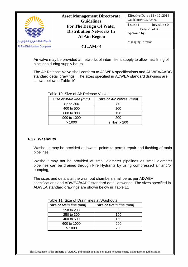
The Air Release Valve shall conform to ADWEA specifications and ADWEA/AADC standard detail drawings. The sizes specified in ADWEA standard drawings are shown below in Table 10
Table 10: Size of Air Release Valves
Size of Main line (mm) Size of Air Valves (mm)
Up to 300 80
400 to 500 100
600 to 800 150
900 to 1000 200
> 1000 2 Nos. x 200
6.27 Washouts
Washouts may be provided at lowest points to permit repair and flushing of main pipelines. Washout may not be provided at small diameter pipelines as small diameter pipelines can be drained through Fire Hydrants by using compressed air and/or pumping, The sizes and details at the washout chambers shall be as per ADWEA specifications and ADWEA/AADC standard detail drawings. The sizes specified in ADWEA standard drawings are shown below in Table 11
Table 11: Size of Drain lines at Washouts
Size of Main line (mm) Size of Drain line (mm)
150 to 200 80
250 to 300 100
400 to 500 150
600 to 1000 200
> 1000 250
Asset Management Directorate
Guidelines
For The Design Of Water
Distribution Networks In
Al Ain Region
GL.AM.01
Effective Date : 11 / 12 /2014
Guideline#: GL.AM.01
Issue : 1 Revision : 0
Page 30 of 38
Approved by:
Managing Director
This Document is the property of AADC, and cannot be used nor given to outside party without prior authorisation
6.28 Fire Hydrants
The aboveground fire hydrant shall be of the breakable pillar type with two nozzles of 2 ½ inches and one nozzle of 4 inches outlet conforming to ADWEA specification.
The underground fire hydrant shall be of screw down type of DN 80 size with screwed 2½ inches round threaded outlet conforming to ADWEA specification. Most of the installed Fire Hydrants in Al Ain are underground type; however the Civil Defence has changed their requirements to use only Pillar type hydrants in water networks. Therefore (unless otherwise specified) only Pillar type shall be specified. The number and location of external fire hydrants is dependent on site planning, building design and the fire risk associated with the development land use. Hydrants are to be positioned along Civil Defence access routes. Hydrants shall be located at 150 m spacing. Hydrants should be clearly visible and marked with approved signage . The details of the fire hydrants shall be as per AADC standard detail drawings.
6.29 Fire Fighting Requirements
The design criteria of fire fighting in water distribution systems in all new developments shall be in accordance to the requirements of the “ Water Distribution Code” published by the RSB and the requirements of the Civil Defence. The Table below summarize the Minimum Fire Fighting Flow requirements stated in the Water Distribution Code (Version 3.0, July 2010).
Table 12: Minimum Fire fighting Flow Requirements (Water Distribution Code)
Characteristic Minimum
Pressure 1.25 bar (12.5 m)
Fire Flow 1800 litre/minute
Network pipe diameter 100 to 150 mm
Fire Duration 120 minutes
Notes : (Abstracted from the WDC)
1- Residual pressure should be measured at the fire hydrants connection with simultaneous design fire flow
discharge and Peak Daily Demand (PDD).
2- Supplementary fire flow may be required for high fire risk premises.
Asset Management Directorate
Guidelines
For The Design Of Water
Distribution Networks In
Al Ain Region
GL.AM.01
Effective Date : 11 / 12 /2014
Guideline#: GL.AM.01
Issue : 1 Revision : 0
Page 31 of 38
Approved by:
Managing Director
This Document is the property of AADC, and cannot be used nor given to outside party without prior authorisation
To determine if there is a need for supplementary fire flow (above and beyond the Minimum fire fighting rates sated in the above table) it will be necessary to assess the fire Risk presented by their proposed land use, having regard for the proposed fire Protection measures, and obtains approval from concerned authorities the number and location of external fire hydrants is dependent on site planning, Building design and the fire risk associated with the development land use Hydrants, Are to be positioned along Civil Defence access routes and in no case should hydrants be located more than 150m apart where applicable.
One fire incident shall be considered for the design of networks at new developments. The velocities and head losses in networks during fire flow may exceed the maximum permissible limits. Also during fire fighting the residual pressure at parts of the water system may be lower than the minimum specified limits but shall not be less than 0.5 bar (5.0 m). AADC has carried out a study to evaluate the fire flow requirements in Al Ain Region and to compare the cost of typical water networks in Al Ain considering different fire flow scenarios. The cost of networks designed to different fire flow scenarios is shown below in Table 13
Table 13: Cost of networks Designed to Different Fire flow scenarios
Fire Flow
Scenario Fire flow requirements
Cost as % of scenario 1
1 A network designed without considering the fire flow in the design but including the cost of fire hydrants.
100 %
2 Fire flow of 1000 litre/minute supplied from two adjacent Fire Hydrants (FH). Min pressure in networks reduced to 5.0 m during fire.
100 %
3 Fire flow of 1800 litre/minute supplied from two adjacent Fire Hydrants (FH). Min pressure in networks reduced to 5.0 m during fire
109 %
4 1800 litre/minute fire flow supplied from one Fire Hydrant (FH). Minimum pressure of 12.5 m in networks during fire.
140 %
The study recommended to apply scenarios 2 and 3 at the areas of low rise residential buildings in Al Ain region as it suit the prevailing fire exposure and fire risks in Al Ain region and at the same time reduce the construction cost of water networks without impacting the safety against fire.
Asset Management Directorate
Guidelines
For The Design Of Water
Distribution Networks In
Al Ain Region
GL.AM.01
Effective Date : 11 / 12 /2014
Guideline#: GL.AM.01
Issue : 1 Revision : 0
Page 32 of 38
Approved by:
Managing Director
This Document is the property of AADC, and cannot be used nor given to outside party without prior authorisation
6.30 Resistivity Survey for Metal Pipelines
Soil resistivity survey may be carried out to determine the corrosivity of the soil along the route of metal pipeline (DI, Steel) to select suitable external coating method. The variations in resistivity along the pipeline routes may be defined within the following bands.
AADC role inside the customer’s premises is limited to approving the size and location of the customer’s tanks, AADC approval is usually provided when customer apply for the service/bulk connections. The total storage at customer’s premises shall be according to the criteria stated by the RSB (Guide to the Water Supply Regulations, Jan 2009). This criteria is summarized as follows :-
1. The total storage capacity (ground tanks and roof tanks or cistern) shall be estimated as follows:- i- Minimum Capacity = 1 x daily consumption + firefighting reserve to be held completely in the ground tank ii- Maximum Capacity = 2 x daily consumption + firefighting reserve to be held completely in the ground tank
2. The roof tank should always be sized to hold sufficient water to supply between 12 and 24 hours of the Premises’ total daily consumption, irrespective of the provision of ground storage tanks. In situations where no ground tanks are allowed for, the actual roof storage capacity shall be sized for 24 hours.
3. For high-consumption customers (such as hotels and hospitals) provided with ground storage tanks only, the complete water capacity may be held in the ground storage tank if the Distribution Company has approved the boosting arrangements.
Asset Management Directorate
Guidelines
For The Design Of Water
Distribution Networks In
Al Ain Region
GL.AM.01
Effective Date : 11 / 12 /2014
Guideline#: GL.AM.01
Issue : 1 Revision : 0
Page 33 of 38
Approved by:
Managing Director
This Document is the property of AADC, and cannot be used nor given to outside party without prior authorisation
6.32 Pumping Stations
6.32.1 Design of Pump Stations
The required pressure in AADC existing and proposed networks usually provided or requested at the interface points with Transco. Accordingly small portion of the distributed water in Al Ain region is supplied through few pump station belong to AADC. These arrangements reduce considerably the need for new pump station in AADC system, but not eliminate the need for pump stations. The pump stations are not covered in details in this design guideline because new pump stations may be rarely required in AADC system. Generally the design works at AADC pump station may be limited to rehabilitation works, upgrading/ improving the capacity and chlorination systems, etc. The design of pumping system shall be according to ADWEA standard specifications.
6.32.2 Water Pumps Configuration
The Configuration of Water Pumps shall be as recommended by the RSB in the WSC as follows :
a. A pump-group(s) in a pumping station shall have a combination of duty and standby pumps.
b. Where more than one pump-group is installed in a pumping station, each
pump-group shall have its own standby pump. c. The level of security shall be between 30% to 40% standby capacity
provided at the pumping station. This is to maintain security of water supply in case duty pump(s) failure (depending on the frequency of the failure) or in planned maintenance situations.
d. The number of standby pumps required to be provided shall be in
accordance with Table 1 shown below. However increased number of standby pumps must be justified by undertaken risk analysis to individual parts of the system to ascertain the optimum number of standby pumps. Increased numbers are also needed to be considered in the case where no alternative supplies is available in the event of frequent failures or to areas classified as critical
Asset Management Directorate
Guidelines
For The Design Of Water
Distribution Networks In
Al Ain Region
GL.AM.01
Effective Date : 11 / 12 /2014
Guideline#: GL.AM.01
Issue : 1 Revision : 0
Page 34 of 38
Approved by:
Managing Director
This Document is the property of AADC, and cannot be used nor given to outside party without prior authorisation
Table 14: Standby Pumps Provision
Number of Duty Pumps
Number of Standby Pumps (standard)
(33%)
Number of Standby Pumps (Increased)
(43%)*
1 1 1
2 1 1
3 1 2
4 1 2
5 2 2
6 2 3
7 3 3
8 3 3
Source : Water Distribution Code
6.32.3 Pump Sizing
All Pumps including fixed speed and variable speed pumps must be capable of supplying output required (pressure and flows) to meet the level of service set by the local supply requirements and also considering the future requirements. The pumps should be able to:
i) Deliver the maximum flows with the pressures required
ii) The duty pump(s) must have adequate capacity to satisfy the flow and pressure requirements of the water distribution system with view to pressure management.
iii) The standby pump(s) shall have the same capacity of the maximum size duty
pump(s) to meet pumping rate, in case any of the duty pump/s is out of service.
Stand-by Generators for Pump Stations Standby generators (either fixed or mobile) shall be provided at sites where no alternative power supply is available (for example, through dual feeds) and where a risk assessment, as per the risk analysis has shown that service to customers is compromised.
Asset Management Directorate
Guidelines
For The Design Of Water
Distribution Networks In
Al Ain Region
GL.AM.01
Effective Date : 11 / 12 /2014
Guideline#: GL.AM.01
Issue : 1 Revision : 0
Page 35 of 38
Approved by:
Managing Director
This Document is the property of AADC, and cannot be used nor given to outside party without prior authorisation
6.33 Water Reservoir
6.33.1 Design of Water Reservoirs
Most of the required storage capacity is provided upstream AADC system such as at Transco system. This arrangement in combination with the RSB requirements of customers tanks of 1 to 2 day demand capacity at each premises reduce considerably the need for new water reservoirs in AADC system, but not eliminate the need for such facility.
As new storage facilities may be rarely required in AADC system, therefore, the water reservoir is not covered in details in this design guideline. Most of the design works at AADC storage facilities is limited to rehabilitation works, etc. The design of storage facilities system shall be carried out according to ADWEA standard specifications.
6.33.2 Sizing of Water Reservoirs
Service reservoirs shall be designed to serve mainly water storage for operational purposes and to balance downstream diurnal variations in demand with relatively constant rates of inflow mainly during high demand.
In addition to provide contingency storage in the event of a failure in transmission system or during maintenance outages. It also provides damping effect so that small fluctuations are not reflected in the Water Distribution System.
In considering the provision of Water Distribution System storage the following shall be taken into consideration :
(a) Volume should be calculated based on Average Daily Demand (ADD)
including fire reserve and the volume of storage so calculated shall be usable and exclusive of any unusable top or bottom water storage.
(b) All water storage facilities should have a minimum of two tanks, or one storage tank with minimum of two section or more that can be isolated, at each location;
Asset Management Directorate
Guidelines
For The Design Of Water
Distribution Networks In
Al Ain Region
GL.AM.01
Effective Date : 11 / 12 /2014
Guideline#: GL.AM.01
Issue : 1 Revision : 0
Page 36 of 38
Approved by:
Managing Director
This Document is the property of AADC, and cannot be used nor given to outside party without prior authorisation
(c) The volume of storage tanks at Distribution pumping station acting as forwarding station to other pump stations and to the network should be based on the Average Daily Demand (ADD) including fire reserve in addition to 10% of the design output to the pump station.
(d) All reservoirs should have interconnecting and bypass arrangements.
6.34 Water Quality in Distribution Networks
AADC receive water at Transco interface points of water quality and residual chlorine rates within the limits defined by the RSB. This arrangement reduce the need for new chlorination facilities in AADC system, but not eliminate the need for such facility. Therefore, the chlorination facilities is not covered in details in this design guidelines.
Most of the design works for chlorination facilities at AADC system may be limited to chlorine re-dosing, rehabilitation, upgrading or replacing the existing chlorination systems.
The design of the chlorination facilities shall be carried out according to ADWEA standard specifications. The designer of the water distribution networks shall consider the water quality by the followings:-
i- Avoid the water stagnation by maintaining reasonable velocities and eliminating
the dead ends
ii- Provide water quality sampling points at selected points in the new distribution networks such as at the DMA feeding points, bulk meters, etc..
iii- Provide water quality instrumentations and sensors at selected points in the new distribution networks such as at the DMA feeding points.
iv- Perform water quality modelling for the new networks if requested by AADC.
v- Provide washout or locate fire hydrants at the areas where water may be stagnated to allow flushing out stagnated water.
Asset Management Directorate
Guidelines
For The Design Of Water
Distribution Networks In
Al Ain Region
GL.AM.01
Effective Date : 11 / 12 /2014
Guideline#: GL.AM.01
Issue : 1 Revision : 0
Page 37 of 38
Approved by:
Managing Director
This Document is the property of AADC, and cannot be used nor given to outside party without prior authorisation
6.35 Protection and Diversion of Existing Pipelines
6.35.1 Protection of Proposed and Existing Pipelines.
Generally all the new pipelines shall cross the existing asphalt roads by Non Destructive Road Crossing (NDRC) methods. The design of the NDRC shall be carried out by the contractor and shall be approved by the concerned authorities including AADC.
The existing pipeline shall be protected by concrete slab if a new road would pass above the existing pipeline. The pipeline shall pass through duct or shall be protected by concrete slab if the road and pipelines would be constructed at same time (i.e. constructed under same project).
6.35.2 Diversion of Existing Pipelines.
The existing pipelines shall be diverted by third parties and at their own cost at the followings cases :- i- The existing pipeline would pass longitudinally under proposed new road or under the embankment of proposed new road. ii- The pipeline become within private plot or need to be diverted due to new planning. Also if the pipeline will become very deep or shallow due to the third party works such as due to new roads crossing the pipelines. iii- The diversion requested by any party other than AADC and approved by AADC. The other diversion cases that not fall under the above categories would be usually designed by AADC and constructed by a contractor appointed by AADC. The party that requested or benefited from the diversion shall design the diversion which shall be of the same size of the existing pipeline and shall submit the design for AADC approval. Also he shall obtain the required approval from other concerned authorities such as TPD. The diversion shall be constructed by the requesting party and at his own cost through a contractor registered with ADWEA for such works. All the construction works shall be carried out under AADC supervision. All the domestic /bulk connections that affected by the diversion shall be relocated on the new pipeline without any cost to AADC.
Asset Management Directorate
Guidelines
For The Design Of Water
Distribution Networks In
Al Ain Region
GL.AM.01
Effective Date : 11 / 12 /2014
Guideline#: GL.AM.01
Issue : 1 Revision : 0
Page 38 of 38
Approved by:
Managing Director
This Document is the property of AADC, and cannot be used nor given to outside party without prior authorisation
6.36 Ducts for Future Water Pipelines.
Ducts for future water pipelines shall be provided under all the new roads in Al Ain region. The AAM/DOT or their representatives shall apply to AADC during the design stage requesting AADC to define the size and location of future ducts under the proposed roads. AAM/DOT or their representatives shall design the future ducts according to the locations and sizes issued by AADC. The AAM/DOT or their representatives shall apply again to AADC during the construction stage requesting the final location and sizes of future ducts. As Built drawing for the constructed ducts shall be submitted to AADC.