gunt Fundamentals of thermodynamics Thermal engineering 1 008 gunt 009 009 008 Introduction Basic knowledge Fundamentals of thermodynamics 010 Basic knowledge Cyclic processes 012 Thermodynamic state variables Basic knowledge Thermodynamic state variables 016 WL 102 Change of state of gases 018 WL 103 Expansion of ideal gases 020 WL 201 Fundamentals of humidity measurement 022 WL 202 Fundamentals of temperature measurement 024 WL 203 Fundamentals of pressure measurement 026 WL 920 Temperature measurement 028 Principles of heat transfer Basic knowledge Material-bound / non-material-bound heat transport 030 WL 362 Energy transfer by radiation 032 WL 372 Radial and linear heat conduction 034 WL 376 Thermal conductivity of building materials 036 WL 377 Convection and radiation 038 Overview GUNT-Thermoline Fundamentals of heat transfer 040 WL 420 Heat conduction in metals 042 WL 422 Heat conduction in fluids 044 WL 430 Heat conduction and convection 046 WL 440 Free and forced convection 048 WL 460 Heat transfer by radiation 050 WL 900 Steady-state and non-steady-state heat conduction 052 Phase transition Basic knowledge Phase transition 054 WL 210 Evaporation process 056 WL 220 Boiling process 058 WL 204 Vapour pressure of water – Marcet boiler 060 WL 230 Condensation process 062
Transcript
guntFundamentals of thermodynamics
Thermal engineering
1
008
gunt
009009008
Introduction
Basic knowledgeFundamentals of thermodynamics 010
Basic knowledgeCyclic processes 012
Thermodynamic state variables
Basic knowledgeThermodynamic state variables 016
WL 102Change of state of gases 018
WL 103Expansion of ideal gases 020
WL 201Fundamentals of humidity measurement 022
WL 202Fundamentals of temperature measurement 024
WL 203Fundamentals of pressure measurement 026
WL 920Temperature measurement 028
Principles of heat transfer
Basic knowledgeMaterial-bound / non-material-bound heat transport 030
WL 362Energy transfer by radiation 032
WL 372Radial and linear heat conduction 034
WL 376Thermal conductivity of building materials 036
WL 377Convection and radiation 038
OverviewGUNT-Thermoline Fundamentals of heat transfer 040
WL 420Heat conduction in metals 042
WL 422Heat conduction in fluids 044
WL 430Heat conduction and convection 046
WL 440Free and forced convection 048
WL 460Heat transfer by radiation 050
WL 900Steady-state and non-steady-state heat conduction 052
Phase transition
Basic knowledgePhase transition 054
WL 210Evaporation process 056
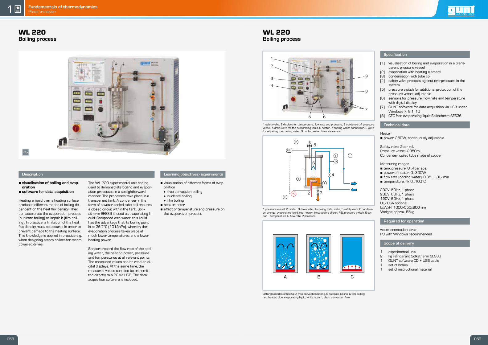
WL 220Boiling process 058
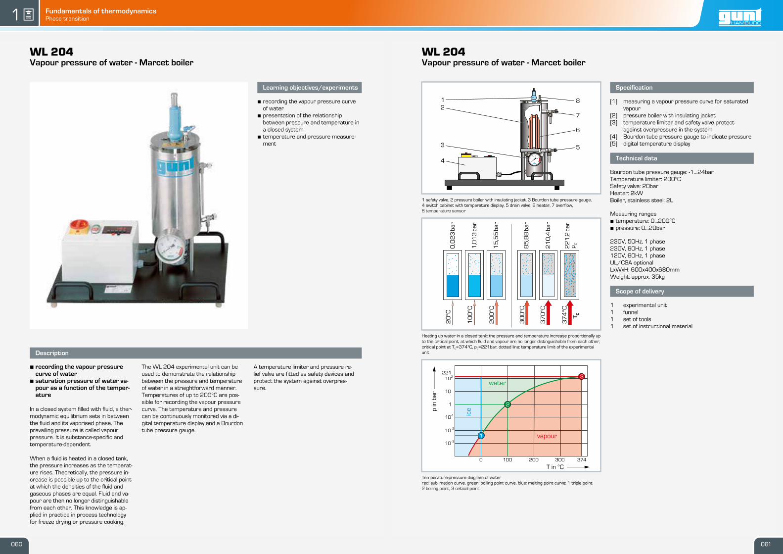
WL 204Vapour pressure of water – Marcet boiler 060
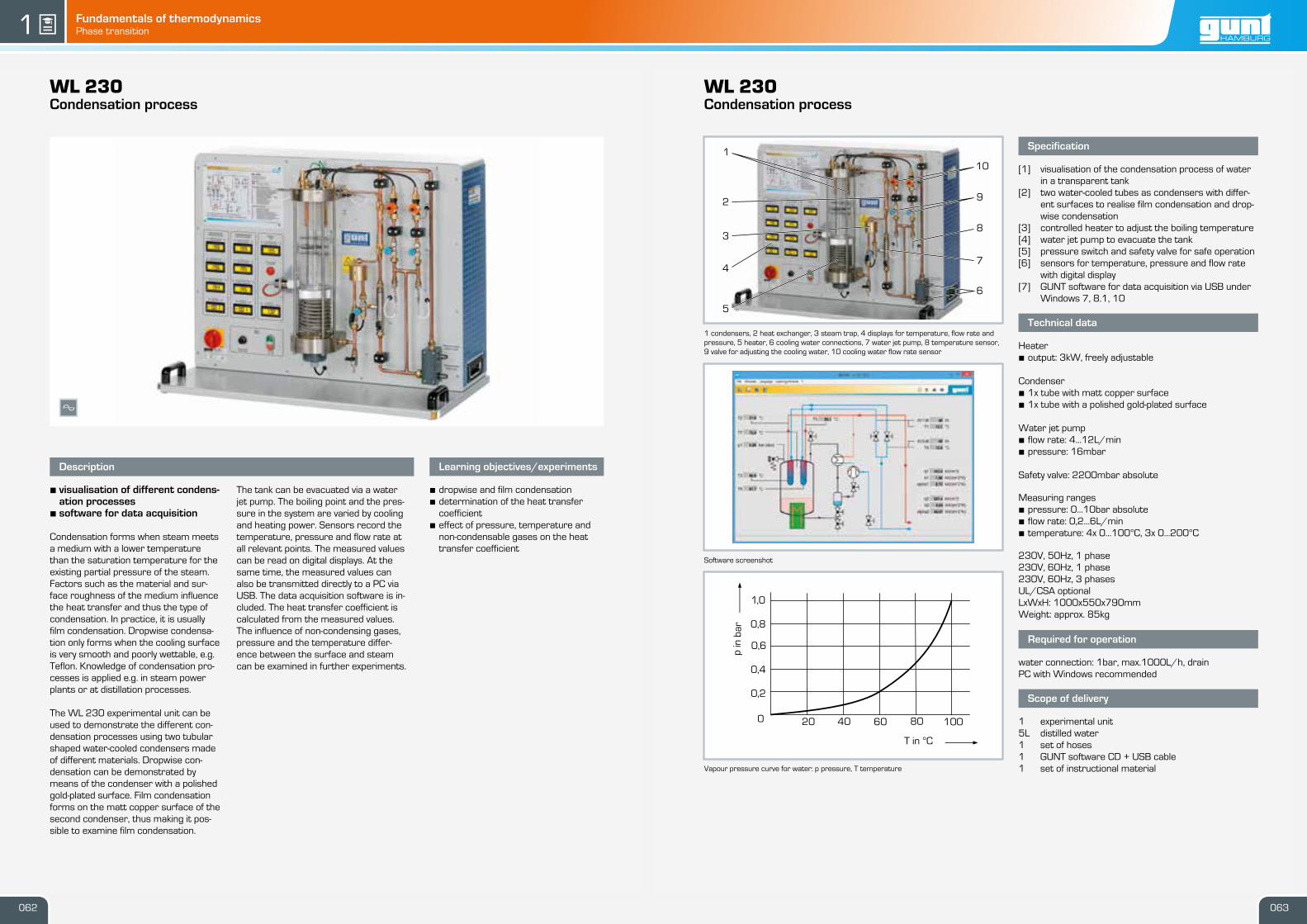
WL 230Condensation process 062
Basic knowledge
Fundamentals of thermodynamics
Fundamentals of thermodynamicsIntroduction gunt1
Thermodynamic systems and principles
Thermodynamic laws
• system: area of the thermodynamic examination
• surroundings: area outside the system
• system boundaries: separation of the system from its surroundings
• process: external impacts on the system
• state: collectivity of measurable properties within the system
• state variables: all measurable properties of the system that can be used to describe its state
• change of state: effect a process has on the state
1st law of thermodynamics
Conservation of energy in thermodynamic systems
Energy can neither be created nor destroyed, it can only be transformed.
The meaning for the three systems is illustrated in the lower left corner.
2nd law of thermodynamics
All natural and technical processes are irreversible.
The second law places a limitation on the first law because, in reality, some energy will dissipate into the surroundings during every process. This energy can neither be used nor transformed back.
3rd law of thermodynamics = Nernst heat theorem
The absolute zero point of 0 Kelvin is a theoretical quantity. It cannot be achieved in practice. The lowest temperature achieved to date is 2 · 10-5 K.
Zeroth law of thermodynamics = law of thermal equilibrium
System A is in thermal equilibrium with system B. System B is in thermal equilibrium with system C. This means that the two systems A and C must also be in thermal equilibrium with each other.
Chronologically, the zeroth law was only formulated after the other three. Since it is fundamental to thermodynamics, it was prepended to the other three laws. This law was therefore designated as 'zeroth' to avoid having to change the names of the laws that had already been assigned.
surroundingssystem boundaries
process
system
state
Open system Closed system Isolated system
Neither mass nor energy cross the system boundaries
Thermodynamic energy conversion can take place inside the system.
No mass crosses the system boundary
The internal system energy increases
Energy or mass can be exchanged with the surroundings outside
the system boundaries
The energy content of the mass flow changes
Example: thermal power plant Example: pressure cooker Example: an ideal thermos flask
fuel air
cooling water
electrical energy
cooling water
emissions
no exchange
isolated system
closed system
energyenergy mass flow
open system
Energy transfer in the form of heat or work has the following effects in the three systems:
The energy is constant
Open system
The energy content of the mass flow changes
Referring to the example of the pressure cooker:
after the inside of the cooker has warmed up, the heat in the cooker cannot flow back into the heating plate.
Closed system
The internal energy changes
Isolated system
The energy is constant
Q
Q
A B AB C C
Thermodynamics is the general theory of energy and material transformation processes: Work is performed by redistributing energy between its different manifestations. The fundamentals of thermodynamics were developed from the study of volume,
pressure, and temperature in steam engines. The following topics are selected based on the devices listed in this chapter.
011010
Basic knowledge
Cyclic processes
Fundamentals of thermodynamicsIntroduction gunt1
013012
Technology uses cyclic thermodynamic processes to describe the conversion of thermal energy to mechanical energy and vice versa.
During this process a medium undergoes periodically different changes of state, such as compression and expansion, evapo-ration and condensation, or heating and cooling over a period of time. In a cyclic process, the medium, after having undergone the different changes of state, goes back to its original state and can thus be reused repeatedly.
Suitable media are substances that remain in a permanent gas-eous state during the cyclic process, such as air or helium, or substances that change their aggregate state during the pro-cess (phase change), like water, ammonia, fl uorocarbons, or CO₂.
When a phase change occurs, more energy is converted than during simple heating or cooling. This means that phase change processes involve a higher energy density and require lower differences in temperature.
Cyclic processes can be used in driving or driven machines. Driving machines convert thermal energy to mechanical energy, such as in steam power plants. Driven machines convert the supplied mechanical energy into thermal energy, like in a com-pression refrigeration system.
Qin
T
s
Qout
Wt<0
Wt
Qin
Qout
Wt>0
T
s
Wt
Representation of cyclic processes in state diagrams
A cyclic thermodynamic process can be illustrated clearly by what are known as state diagrams. The most commonly used state diagrams are:
• p-v diagram: pressure p against specifi c volume v, suitable for representing mechanical power. It is often used for recip-rocating compressors and internal combustion engines with a purely gaseous working medium. Here, cyclic processes can be observed quite well because there is a fi xed relationship between volume change and time. The enclosed area is a mea-sure for the mechanical work performed, also known as useful work.
• h-s diagram: enthalpy h against entropy s, for representation of steam turbine processes. It is used for water steam and is well suited as a tool for designing steam turbines.
• log p-h diagram: logarithmic representation of the pressure p against the specifi c enthalpy h, particularly well suited for cooling processes in refrigeration engineering, as heat fl uxes
can be read from the diagram directly as horizontal lines. For the vertical pressure scale, a logarithmic division is used, as this is a good way to represent phase limit curves.
• T-s diagram: a plot of temperature T against entropy s, used for the representation of the thermodynamic conditions. The direction of the cyclic process indicates the type of system, driving or driven machine. If the cycle goes clockwise, the sys-tem is a driving machine, and if it goes counter-clockwise, it is a driven machine. In the clockwise direction, heat is absorbed at a high temperature and released at a low temperature. In the counter-clockwise direction, heat is absorbed at a low temperature and released at a high temperature. If the sys-tem is operated in the counter-clockwise direction, it is thus suitable as a heat pump or refrigeration machine. As in the p-v diagram, the enclosed area is a measure of the useful work performed.
Wt useful work, Q thermal energy, T temperature, s entropy
Type Driving or driven machine Working medium Aggregate state
Steam power plant driving water liquid/gaseous
Internal combustion engine driving air/combustion gas gaseous
Gas turbine driving air/combustion gas gaseous
Stirling engine driving air, helium gaseous
ORC power plant (Organic Rankine Cycle)
driving fl uorocarbons,hydrocarbons
liquid/gaseous
Refrigeration machine driven fl uorocarbons, hydrocarbons,ammonia, etc.
liquid/gaseous
Stirling refrigeration system driven air, helium gaseous
p=const
v=co
nst
s
T
Wt
Q
s=
const
T=const
T=consts=const
v
p
The following section presents some technically relevant cyclic processes with their diagrams.
In the T-s diagram, the Carnot process forms a rectangle. The area of the rectangle is a measure of the useful work Wt. The area between the temperature zero and the maximum process temperature is a measure of the required thermal energy Q. This means that the following effi ciency η results are derived for the Carnot process:
The maximum effi ciency of a cyclic thermodynamic process thus only depends on the absolute maximum and minimum tempera-tures, Tmax and Tmin. This means that the Carnot process allows statements regarding the quality of any technical cyclic pro-cess. Furthermore, it is clear that every thermodynamic pro-cess requires a difference in temperatures to perform work. The effi ciency of the Carnot process is the highest theoretically possible effi ciency of a cyclic process.
The changes of state that are necessary for the Carnot process, like isothermal and isentropic compression and/or expansion, are diffi cult to realise technically. Despite its high effi ciency, this process is therefore of theoretical interest only.
The p-v diagram on the right shows another crucial disadvan-tage of the Carnot process. Despite large differences in pres-sure and volume, the surface area of the diagram, and thus the mechanical work performed, is very small. When the Carnot process is applied, this translates to a large and heavy machine with a small output.
The Carnot process
Carnot process in T-s diagram
Carnot process in p-v diagram
Wt useful work, Q thermal energy, T temperature, p pressure, v specifi c volume, s entropy
η = =Tmax - Tmin
TmaxQ
Wt
Basic knowledge
Cyclic processes
Fundamentals of thermodynamicsIntroduction gunt1
015014
2
1
3
5
4
A
B H
GC
D E
F
A
B
C DE
2 6
541
3
600
500
400
300
200
100
0
s in kJ/kgK
T in
°C
0 2 4 6 8
3
20
0ba
r15
0ba
r
10ba
r
50
bar
100
bar
2
541
1,0
bar
0,2
bar
0,04
bar
1bar
2bar
4bar
6bar
10bar
20bar40bar60bar100bar
3
0,02
9m/k
g
3
0,04
2m/k
g
3
0,05
6m/k
g
3
0,09
2m/k
g
3
0,15
1m/k
g
3
0,21
8m/k
g3
0,29
1m/k
g3
0,478
m/k
g3
0,784m
/kg
s in kJ/kgKT
in °
C0,0 0,3 0,6 0,9
1400
1200
1000
800
600
400
200
0
4
1
5
2
6
3
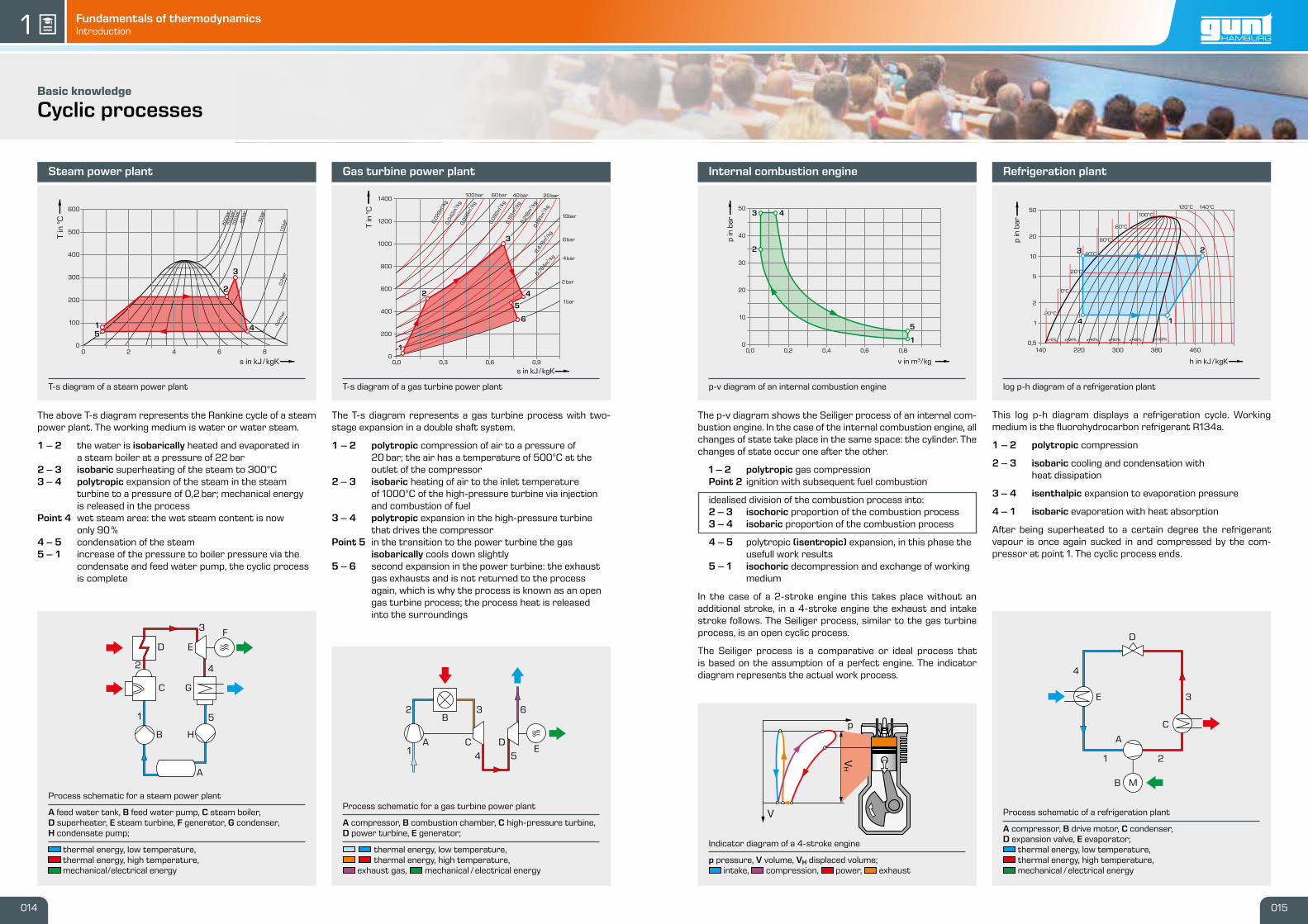
T-s diagram of a gas turbine power plantT-s diagram of a steam power plant
Gas turbine power plantSteam power plant
The T-s diagram represents a gas turbine process with two-stage expansion in a double shaft system.
1 – 2 polytropic compression of air to a pressure of 20 bar; the air has a temperature of 500°C at the outlet of the compressor2 – 3 isobaric heating of air to the inlet temperature of 1000°C of the high-pressure turbine via injection and combustion of fuel3 – 4 polytropic expansion in the high-pressure turbine that drives the compressorPoint 5 in the transition to the power turbine the gas isobarically cools down slightly5 – 6 second expansion in the power turbine: the exhaust gas exhausts and is not returned to the process again, which is why the process is known as an open gas turbine process; the process heat is released into the surroundings
The above T-s diagram represents the Rankine cycle of a steam power plant. The working medium is water or water steam.
1 – 2 the water is isobarically heated and evaporated in a steam boiler at a pressure of 22 bar2 – 3 isobaric superheating of the steam to 300°C3 – 4 polytropic expansion of the steam in the steam turbine to a pressure of 0,2 bar; mechanical energy is released in the processPoint 4 wet steam area: the wet steam content is now only 90%4 – 5 condensation of the steam5 – 1 increase of the pressure to boiler pressure via the condensate and feed water pump, the cyclic process is complete
Process schematic for a steam power plant
A feed water tank, B feed water pump, C steam boiler, D superheater, E steam turbine, F generator, G condenser,H condensate pump;
thermal energy, low temperature, thermal energy, high temperature, mechanical/electrical energy
Process schematic for a gas turbine power plant
A compressor, B combustion chamber, C high-pressure turbine, D power turbine, E generator;
thermal energy, low temperature, thermal energy, high temperature, exhaust gas, mechanical /electrical energy
log p-h diagram of a refrigeration plant
Refrigeration plant
D
C
B
E
A
4
3
21
40°C
4 1
23
h in kJ/kgK
p in
bar
50
20
10
5
2
1
0,5140 220 300 380 460
120°C 140°C
100°C
60°C
20°C
0°C
80°C
-20°C
v in m3/kg
0,0 0,2 0,4 0,6 0,8
p in
bar
50
40
30
20
10
0
43
5
1
2
p
V
VH
p-v diagram of an internal combustion engine
Internal combustion engine
The p-v diagram shows the Seiliger process of an internal com-bustion engine. In the case of the internal combustion engine, all changes of state take place in the same space: the cylinder. The changes of state occur one after the other.
1 – 2 polytropic gas compression Point 2 ignition with subsequent fuel combustion
idealised division of the combustion process into:2 – 3 isochoric proportion of the combustion process3 – 4 isobaric proportion of the combustion process
4 – 5 polytropic (isentropic) expansion, in this phase the usefull work results5 – 1 isochoric decompression and exchange of working medium
In the case of a 2-stroke engine this takes place without an additional stroke, in a 4-stroke engine the exhaust and intake stroke follows. The Seiliger process, similar to the gas turbine process, is an open cyclic process.
The Seiliger process is a comparative or ideal process that is based on the assumption of a perfect engine. The indicator diagram represents the actual work process.
Indicator diagram of a 4-stroke engine
p pressure, V volume, VH displaced volume; intake, compression, power, exhaust
Process schematic of a refrigeration plant
A compressor, B drive motor, C condenser, D expansion valve, E evaporator;
thermal energy, low temperature, thermal energy, high temperature, mechanical /electrical energy
This log p-h diagram displays a refrigeration cycle. Working medium is the fl uorohydrocarbon refrigerant R134a.
1 – 2 polytropic compression
2 – 3 isobaric cooling and condensation with heat dissipation
3 – 4 isenthalpic expansion to evaporation pressure
4 – 1 isobaric evaporation with heat absorption
After being superheated to a certain degree the refrigerant vapour is once again sucked in and compressed by the com-pressor at point 1. The cyclic process ends.
Basic knowledge
Thermodynamic state variables
Fundamentals of thermodynamicsThermodynamic state variables gunt1
Thermodynamic systems and principles
surroundingssystem boundaries
process
system
state
State variables are the measurable properties of a system. To describe the state of a system at least two independent state variables must be given.
State variables are e.g.:
• pressure (p)
• temperature (T)
• volume (V)
• amount of substance (n)
• internal energy (U): the thermal energy of a static, closed system. When external energy is added, processes result in a change of the internal energy. ∆U = Q+W
· Q: thermal energy added to the system, · W: mechanical work done on the system that results in an addition of heat
• enthalpy (H): defined as the sum of internal energy plus work p ×V H = U+p×V
• entropy (S): provides information on the order in a sys-tem and the associated arrangement options of particles in that system The change in entropy dS is known as reduced heat. dS = δQrev/T
· δQrev: reversible heat change · T: absolute temperature
When the steam engine was developed more than 200 years ago, physicists wondered why only a few percent of the thermal energy was converted into mechanical energy. Rudolf Clausius introduced the term entropy to explain why the efficiency of thermal engines is limited to a few percent. Thermal engines convert a temperature difference into mechanical work. Thermal engines include steam engines, steam turbines or internal combustion engines.
The state functions can be derived from the state variables:
An increase in the internal energy of the system using a pressure cooker as an example.
V6 engine of a racing car
Steam engine
Disassembled steam turbine rotor
Changes of state can be clearly illustrated in diagrams
p
V
T
S
Change of state of gases
In physics, an idealised model of a real gas was introduced to make it easier to explain the behaviour of gases. This model is a highly simplified representation of the real states and is known as an “ideal gas”. Many thermodynamic processes in gases in particular can be explained and described mathematically with the help of this model.
Equation of state for ideal gases: p × V = m × Rs × T
· m: mass · Rs: spec. gas constant of the corresponding gas
Changes of state of an ideal gas
Change of state isochoric isobaric isothermal isentropic
Condition V = constant p = constant T = constant S = constant
The changes of state listed above are special cases of polytropic change of state, in which part of the heat is exchanged with the environment.
isochoric n —> ∞ isobaric n = 0 isothermal n = 1 isentropic n = κ
Polytropic changes of state with different heat exchange: n<κ heat dissipation n>κ heat absorption
p,V diagramT-s diagram
p,V-diagram
017016
Fundamentals of thermodynamicsThermodynamic state variables gunt1 gunt
WL 102Change of state of gases
1 tank 1 for isothermic change of state, 2 digital displays, 3 5/2-way valve for switchingbetween compression and expansion, 4 heating controller, 5 tank 2 for isochoric change ofstate
Representation of the change of volume1 oil-filled tank for isothermic change of state, 2 valve arrangement with compressor,3 storage tank; A compression (blue), B expansion (red)
Software screenshot: charts for isothermic compression
Specification
[1] experimental investigation of gas laws[2] transparent measuring tank 1 for investigation of
isothermic change of state[3] hydraulic oil filling for changing volume of test gas[4] built-in compressor generates necessary pressure
differences to move the oil volume[5] compressor can also be used as vacuum pump[6] 5/2-way valve for switching between compression
and expansion[7] transparent measuring tank 2 for investigation of
isochoric change of state[8] electrical heater with temperature control in tank 2[9] sensors and digital displays for temperatures, pres-
sures and volumes[10] GUNT software for data acquisition via USB under
Windows 7, 8.1, 10
Technical data
Compressor / vacuum pump• power output: 60W• pressure at inlet: 213mbar• pressure at outlet: 2barTemperature controller: PID, 300W, limited to 80°C
Measuring ranges• temperature:· tank 1: 0…80°C· tank 2: 0…80°C
• pressure:· tank 1: 0…4bar abs.· tank 2: 0…2bar abs.
We reserve the right to modify our products without any notifications. Page 2/3 - 03.2018
guntWL 102Change of state of gases
x
Description
• isothermal and isochoric changeof state of air
• GUNT software for acquisition,processing and display of meas-ured data
Gas laws belong to the fundamentals ofthermodynamics and are dealt with inevery training course on thermodynam-ics.
The WL 102 experimental unit enablestwo changes of state to be studied ex-perimentally: isothermal change of state,also known as the Boyle-Mariotte law,and isochoric change of state, which oc-curs at constant volume. Transparenttanks enable the change of state to beobserved. Air is used as the test gas.
In the first tank, positioned on the left,the hermetically enclosed air volume isreduced or increased using a com-pressor and hydraulic oil. This results inan isothermal change of state. The com-pressor can also operate as a vacuumpump. If the changes occur slowly, thechange of state takes place at an almostconstant temperature.
In the second tank, positioned on theright, the temperature of the test gas isincreased by a controlled electric heaterand the resulting pressure rise is meas-ured. The volume of the enclosed gas re-mains constant. Temperatures, pres-sures and volumes are measured elec-tronically, digitally displayed and trans-ferred to a PC for processing.
Learning objectives/experiments
• demonstrating the laws of statechanges in gases experimentally
• isothermal change of state, Boyle-Mari-otte law
• isochoric change of state, Gay-Lus-sac’s 2nd law
1 ball valve, 2 compressor, 3 negative pressure tank, 4 safety valve, 5 positive pressuretank; P pressure, T temperature
Schematic diagram of a typical experiment according to Clément-Desormes;p pressure, T temperature, t time, red: temperature, green: pressure
Specification
[1] behaviour of ideal gases[2] precise measurement of pressures and temperat-
ures[3] transparent components[4] experiment according to Clément-Desormes[5] determination of the adiabatic exponent of air[6] GUNT software with control functions and data ac-
We reserve the right to modify our products without any notifications. Page 2/3 - 02.2018
guntWL 103Expansion of ideal gases
x
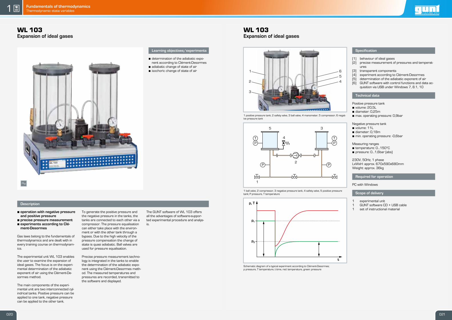
Description
• operation with negative pressureand positive pressure
• precise pressure measurement• experiments according to Clé-
ment-Desormes
Gas laws belong to the fundamentals ofthermodynamics and are dealt with inevery training course on thermodynam-ics.
The experimental unit WL 103 enablesthe user to examine the expansion ofideal gases. The focus is on the experi-mental determination of the adiabaticexponent of air using the Clément-De-sormes method.
The main components of the experi-mental unit are two interconnected cyl-indrical tanks. Positive pressure can beapplied to one tank, negative pressurecan be applied to the other tank.
To generate the positive pressure andthe negative pressure in the tanks, thetanks are connected to each other via acompressor. The pressure equalisationcan either take place with the environ-ment or with the other tank through abypass. Due to the high velocity of thepressure compensation the change ofstate is quasi adiabatic. Ball valves areused for pressure equalisation.
Precise pressure measurement techno-logy is integrated in the tanks to enablethe determination of the adiabatic expo-nent using the Clément-Desormes meth-od. The measured temperatures andpressures are recorded, transmitted tothe software and displayed.
The GUNT software of WL 103 offersall the advantages of software-suppor-ted experimental procedure and analys-is.
Learning objectives/experiments
• determination of the adiabatic expo-nent according to Clément-Desormes
• adiabatic change of state of air• isochoric change of state of air
We reserve the right to modify our products without any notifications. Page 1/3 - 02.2018021020
1
2
35
4
PP
TTPP
p1
p, T
t
p2
1 6
25
3
4
Fundamentals of thermodynamicsThermodynamic state variables gunt1 gunt
WL 201Fundamentals of humidity measurement
1 capacitive humidity sensor, 2 displays and controls, 3 humidifier, 4 psychrometer, 5 hairhygrometer, 6 dehumidifier, 7 hygrometer with synthetic fibre and combined temperaturesensor
Principle of the hair hygrometer: 1 mechanism to measure the humidity-dependent changein length of the hair bundle, 2 hair bundle, 3 humidity scale
Relative humidity (r. h.) over time (t) with rising content of humidity; blue: capacitive sensor,orange: hygrometer with synthetic fibre, red: psychrometer, green: hair hygrometer
Specification
[1] different measuring methods for measuring humid-ity
[2] climatic chamber with adjustable humidity andtransparent door
[3] humidification via ultrasonic atomiser[4] dehumidification via Peltier cooling element[5] fan for air recirculation[6] 2 mechanical instruments: psychrometer, hair hy-
meter with synthetic fibre and combined temperat-ure sensor
Technical data
Humidifier• ultrasonic atomiser• power consumption: 21,6W• low water cut-off Dehumidifier• Peltier element· cooling capacity: 56,6W (50°C ambient temperat-
ure)· cooling surface: 1600mm2
Hair hygrometer with deflective needle• measuring range: 0…100% r. h. Hygrometer with synthetic fibre• output voltage: 0…10V• measuring ranges: 0…100% r. h. / -30…80°C Capacitive sensor with digital display• output voltage: 0…10V• measuring range: 1…100% r. h. Psychrometer with thermometer• measuring range: -10…60°C, graduation: 0,5°C
We reserve the right to modify our products without any notifications. Page 2/2 - 03.2018
guntWL 201Fundamentals of humidity measurement
Description
• different measuring methods formeasuring humidity
• climatic chamber with adjustablehumidity and transparent door
The measurement of air humidity playsan important role in many branches ofindustry, e.g. during drying or in the airconditioning of buildings and vehicles.There are different measuring methodsto determine humidity.
The trainer WL 201 enables the meas-urement of air humidity with four differ-ent instruments which can be directlycompared to each other: two differenthygrometers, a capacitive hygrometerand a psychrometer.
Psychrometers operate based on theprinciple of evaporation cooling andcompare the ambient temperature withthe wet bulb temperature to determinethe humidity. Hygrometers utilise theproperty of specific fibres, e.g. hair, toexpand with increasing air humidity. Inthe capacitive sensor the dielectricityconstant of a layer and with it its capa-city changes due to the water moleculesabsorbed.
The core element of the trainer is a cli-matic chamber with transparent door.This chamber can be humidified and de-humidified and contains the four instru-ments. A Peltier cooling element is usedfor dehumidification. An ultrasonic atom-iser is used for humidification. To circu-late the air and ensure good mixing afan is used.
Learning objectives/experiments
• measuring methods for air humiditymeasurement· psychrometric humidity measure-
We reserve the right to modify our products without any notifications. Page 1/2 - 03.2018023022
1
2
3
45
6
7
50
65
100%0%
1
2
3
40
50
60
70
80
90
100
110
r.H. i
n %
t
Fundamentals of thermodynamicsThermodynamic state variables gunt1 gunt
WL 202Fundamentals of temperature measurement
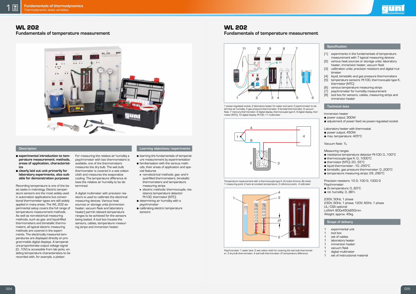
1 power-regulated socket, 2 laboratory heater for water and sand, 3 psychrometer to de-termine air humidity, 4 gas pressure thermometer, 5 bimetal thermometer, 6 vacuumflask, 7 mercury thermometer, 8 digital display, thermocouple type K, 9 digital display, ther-mistor (NTC), 10 digital display, Pt100, 11 multimeter
Temperature measurement with a thermocouple type K: A) nickel chrome, B) nickel;1 measuring point, 2 tank at constant temperature, 3 reference point, 4 voltmeter
Psychrometer: 1 water tank, 2 wet cotton cloth for covering the wet bulb thermomet-er, 3 dry bulb thermometer, 4 wet bulb thermometer; dT temperature difference
Specification
[1] experiments in the fundamentals of temperaturemeasurement with 7 typical measuring devices
[2] various heat sources or storage units: laboratoryheater, immersion heater, vacuum flask
[3] calibration units: precision resistors and digital mul-timeter
[4] liquid, bimetallic and gas pressure thermometers[5] temperature sensors: Pt100, thermocouple type K,
thermistor (NTC)[6] various temperature measuring strips[7] psychrometer for humidity measurement[8] tool box for sensors, cables, measuring strips and
immersion heater
Technical data
Immersion heater• power output: 300W• adjustment of power feed via power-regulated socket
Laboratory heater with thermostat• power output: 450W• max. temperature: 425°C
Vacuum flask: 1L
Measuring ranges• resistance temperature detector Pt100: 0…100°C• thermocouple type K: 0…1000°C• thermistor (NTC): 20…55°C• liquid thermometer: -10…250°C• bimetallic, gas pressure thermometer: 0…200°C• temperature measuring strips: 29…290°C
We reserve the right to modify our products without any notifications. Page 2/3 - 02.2018
guntWL 202Fundamentals of temperature measurement
Description
• experimental introduction to tem-perature measurement: methods,areas of application, characterist-ics
• clearly laid out unit primarily forlaboratory experiments, also suit-able for demonstration purposes
Recording temperature is one of the ba-sic tasks in metrology. Electric temper-ature sensors are the most widely usedin automation applications but conven-tional thermometer types are still widelyapplied in many areas. The WL 202 ex-perimental setup covers the full range oftemperature measurement methods.As well as non-electrical measuringmethods, such as gas- and liquid-filledthermometers and bimetallic thermo-meters, all typical electric measuringmethods are covered in the experi-ments. The electrically measured tem-peratures are displayed directly on pro-grammable digital displays. A temperat-ure-proportionate output voltage signal(0…10V) is accessible from lab jacks, en-abling temperature characteristics to berecorded with, for example, a plotter.
For measuring the relative air humidity apsychrometer with two thermometers isavailable, one of the thermometersmeasures the dry bulb. The wet bulbthermometer is covered in a wet cottoncloth and measures the evaporativecooling. The temperature difference al-lows the relative air humidity to be de-termined.
A digital multimeter with precision res-istors is used to calibrate the electricalmeasuring devices. Various heatsources or storage units (immersionheater, vacuum flask and laboratoryheater) permit relevant temperatureranges to be achieved for the sensorsbeing tested. A tool box houses thesensors, cables, temperature measur-ing strips and immersion heater.
Learning objectives/experiments
• learning the fundamentals of temperat-ure measurement by experimentation
• familiarisation with the various meth-ods, their areas of application and spe-cial features· non-electrical methods: gas- and li-
quid-filled thermometers, bimetallicthermometers and temperaturemeasuring strips
· electric methods: thermocouple, res-istance temperature detectorPt100, thermistor (NTC)
Fundamentals of thermodynamicsThermodynamic state variables gunt1 gunt
WL 203Fundamentals of pressure measurement
1 U-tube manometer, 2 inclined tube manometer, 3 calibration device with Bourdon tubepressure gauge, 4 Bourdon tube pressure gauge for positive pressure, 5 Bourdon tubepressure gauge for negative pressure
Principle of operation of liquid column manometers1 U-tube manometer, 2 inclined tube manometer; dp pressure difference, dh height differ-ence, rho density of measuring fluid, g acceleration of gravity
Principle of operation of a Bourdon tube pressure gauge1 scale, 2 pointer, 3 Bourdon tube fixed in place, 4 gearing, 5 tie rod, 6 Bourdon tubewithout pressure, 7 Bourdon tube expanded under pressure
Specification
[1] basic experiments for measuring pressure withthree different measuring instruments
[2] U-tube and inclined tube manometer[3] one Bourdon tube pressure gauge each for positive
and negative pressure[4] plastic syringe generates test pressures in the mil-
libar range[5] calibration device with Bourdon tube pressure
We reserve the right to modify our products without any notifications. Page 2/3 - 03.2018
guntWL 203Fundamentals of pressure measurement
Description
• comparison of different pressuremeasurement methods
• measuring positive and negativepressure
• calibration device with Bourdontube pressure gauge for calibrat-ing mechanical manometers
Measuring pressure is important in theengineering industry, e.g. in plant, tur-bomachine and aircraft constructionand in process engineering. Other funda-mental factors such as flow rate or flowvelocity can also be determined basedon a pressure measurement.
The WL 203 experimental unit enablesthe user to measure the pressure withtwo different measuring methods: dir-ectly by measuring the length of a liquidcolumn (U-tube manometer, inclinedtube manometer) and indirectly bymeasuring the change of shape of aBourdon tube (Bourdon tube pressuregauge).
In a U-tube manometer, the pressurecauses the liquid column to move. Thepressure difference is read directly froma scale and is the measure for the ap-plied pressure. In inclined tube mano-meters, one leg points diagonally up. Asmall height difference therefore
changes the length of the liquid columnsignificantly.
The principle of the Bourdon tube pres-sure gauge is based on the change incross-section of the bent Bourdon tubeunder pressure. This change in cross-section leads to an expansion of theBourdon tube diameter. A Bourdon tubepressure gauge is therefore an indir-ectly acting pressure gauge where thepressure differential is indicated via atransmission gearing and a pointer.
In experiments, pressures in the millibarrange are generated with a plastic syr-inge and displayed on the manometers.The experimental unit is equipped withtwo Bourdon tube pressure gauges formeasuring positive and negative pres-sure. The U-tube manometer, inclinedtube manometer and Bourdon tubepressure gauges at the experimentalunit can be combined using tubes. A cal-ibration device enables calibration of anadditional Bourdon tube pressure gaugeusing a weight-loaded piston manomet-er.
Learning objectives/experiments
• familiarisation with 2 different measur-ing methods:· direct method with U-tube manomet-
er and inclined tube manometer· indirect method with Bourdon tube
pressure gauge• principle of a Bourdon tube pressure
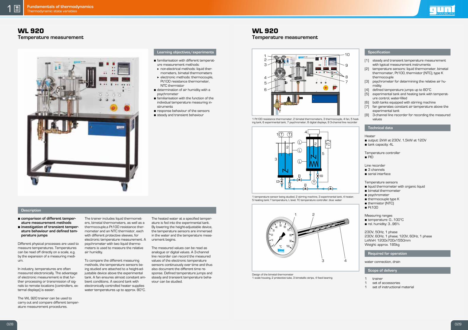
1 temperature sensor being studied, 2 stirring machine, 3 experimental tank, 4 heater,5 heating tank; T temperature, L level, TC temperature controller, blue: water
Design of the bimetal thermometer1 scale housing, 2 protective tube, 3 bimetallic strips, 4 fixed bearing
Specification
[1] steady and transient temperature measurementwith typical measurement instruments
[2] temperature sensors: liquid thermometer, bimetalthermometer, Pt100, thermistor (NTC), type Kthermocouple
[3] psychrometer for determining the relative air hu-midity
[4] defined temperature jumps up to 80°C[5] experimental tank and heating tank with temperat-
ure control, water-filled[6] both tanks equipped with stirring machine[7] fan generates constant air temperature above the
experimental tank[8] 3-channel line recorder for recording the measured
values
Technical data
Heater• output: 2kW at 230V, 1,5kW at 120V• tank capacity: 4L Temperature controller• PID Line recorder• 3 channels• serial interface Temperature sensors• liquid thermometer with organic liquid• bimetal thermometer• psychrometer• thermocouple type K• thermistor (NTC)• Pt100
We reserve the right to modify our products without any notifications. Page 2/2 - 02.2018
guntWL 920Temperature measurement
Description
• comparison of different temper-ature measurement methods
• investigation of transient temper-ature behaviour and defined tem-perature jumps
Different physical processes are used tomeasure temperatures. Temperaturescan be read off directly on a scale, e.g.by the expansion of a measuring medi-um.
In industry, temperatures are oftenmeasured electronically. The advantageof electronic measurement is that fur-ther processing or transmission of sig-nals to remote locations (controllers, ex-ternal displays) is easier.
The WL 920 trainer can be used tocarry out and compare different temper-ature measurement procedures.
The trainer includes liquid thermomet-ers, bimetal thermometers, as well as athermocouple,a Pt100 resistance ther-mometer and an NTC thermistor, eachwith different protective sleeves, forelectronic temperature measurement. Apsychrometer with two liquid thermo-meters is used to measure the relativeair humidity.
To compare the different measuringmethods, the temperature sensors be-ing studied are attached to a height-ad-justable device above the experimentaltank. A fan ensures almost constant am-bient conditions. A second tank withelectronically controlled heater supplieswater temperatures up to approx. 80°C.
The heated water at a specified temper-ature is fed into the experimental tank.By lowering the height-adjustable device,the temperature sensors are immersedin the water and the temperature meas-urement begins.
The measured values can be read asanalogue or digital values. A 3-channelline recorder can record the measuredvalues of the electronic temperaturesensors continuously over time and thusalso document the different time re-sponse. Defined temperature jumps andsteady and transient temperature beha-viour can be studied.
Learning objectives/experiments
• familiarisation with different temperat-ure measurement methods:· non-electrical methods: liquid ther-
We reserve the right to modify our products without any notifications. Page 1/2 - 02.2018029028
I ON
OOFF
HAUPTSCHALTERÖFFNEN IN
O - STELLUNG
MAIN SWITCHOPEN IN
OFF - POSITION
DSP PAR RSTF1 F1
MAX
MIN
TOTV
DSP PAR RSTF1 F1
MAX
MIN
TOTV
DSP PAR RSTF1 F1
MAX
MIN
TOTV
0I
0I
WL 920Versuchsstand für Temperatur-MesstechnikAdvanced Temperature Measurement Trainer
6080
70
°C
90100110
120
5040
302010
0
123
4
6
5 78
9
10
L1
T T
T
L1L
L
L
TC
4
22
1
3
5
43
21
Basic knowledge
Material-bound / non-material-bound heat transport
Fundamentals of thermodynamicsPrinciples of heat transfer gunt1
by conduction and convection by thermal radiation
Material-bound heat transport Non-material-bound heat transport
Conduction
In the case of thermal conduction, heat transport takes place through direct interaction between the molecules (e.g. molecule collisions) within a solid or a fluid at rest. A prerequisite for this is that there is a temperature difference within the substance or that substances of different temperatures come into direct contact with each other. All aggregate states allow this transfer mechanism.
The amount of heat transported depends on:
• the thermal conductivity λ of the material,• the heat conducting length L,• the heat transferring area A,• the dwell time t and• the temperature difference ΔT between the beginning and
end of the thermal conductor
Radiation
Energy transport through electromagnetic oscillation in a spe-cific wavelength range. Any body with a temperature above zero Kelvin emits radiation known as thermal radiation.
Thermal radiation includes UV radiation, light radiation and infrared radiation. Light radiation covers the wavelength range visible to the human eye.
Material characteristics
Heat transfer coefficient α: a measure of how much heat is transferred from a solid to a fluid or vice versa (convection)
Thermal conductivity λ: a measure of how well heat is trans-ferred into a solid (conduction)
Overall heat transfer coefficient k: describes the overall heat transfer between fluids separated by solids (convection and conduction)
Reflectance, absorbance and transmittance: a measure of the proportion of thermal radiation reflected, absorbed or transmit-ted to a body (radiation)
Convection
Heat transport takes place in flowing liquids or gases by means of material movement, i.e. material transport. Where forced convection occurs, the flow is forced by external forces. Exam-ples: a pump in a warm water heater, fans in a power pack or PC.
If the flow is caused by differences in density due to different temperatures within the fluid this is called free or natural con-vection. Examples: water movement when heated in a pot, by a foehn wind, the gulf stream, or a vent in a chimney.
The hot stove transfers the heat to the water through the bottom of the saucepan with the cross-sectional area A.
The red arrows indicate the direction of the heat flux.
The heat is transferred from the hot to the cold material along the heat-conducting length L due to the interaction of the molecules via the temperature difference ΔT.
2 200,50,2 5 5010,1 10 100
10-10
10-7
10-4
10-1
Using a thermal imaging camera, it is possible to make thermal radiation visible: the thermal camera converts long-wave infrared radiation into visible radiation.
The air molecules warmed by the heater rise due to differences in density.
Cold air is sucked in by the fan, cools the internal components and flows out again as heated air.
The best example of ther-mal radiation is the sun. One example of a technical application is a patio heater: electromagnetic oscillations are emitted by the heat source as thermal radiation in all directions. The portion of the thermal radiation directed upwards is reflected by the canopy.
A
L
ΔT
IR radiationUV radiation
Visible radiation = light
MicrowavesX-ray radiationThermal radiation
λ in μm
λ in m
031030
Fundamentals of thermodynamicsPrinciples of heat transfer gunt1 gunt
WL 362Energy transfer by radiation
1 measuring amplifier, 2 optical bench with scale for reading the distances, 3 pivoting lightsource, 4 holder for slit diaphragm or optional colour filter (red, green, infrared), 5 luxmet-er, 6 absorption plates and reflection plate each with temperature measuring point, 7 ther-mopile, 8 thermal radiator
Spectrum of thermal radiationtop scale wavelength λ in m, bottom scale wavelength λ in µm
Software screenshot: investigations on the distance to the radiation source
Specification
[1] thermal radiator and thermopile for the investiga-tion of thermal radiation
[2] light source and luxmeter for the investigation of il-luminance
[3] absorption plate and reflection plate with thermo-couples for the investigation of Kirchhoff’s laws
[4] adjustable radiant power of thermal radiator andlight source
[5] 3 colour filters with holder (red, green, infrared), slitdiaphragm
[6] luxmeter for measuring illuminance[7] thermocouple for measuring the temperature[8] thermopile for measuring radiant power[9] GUNT software for data acquisition via USB under
We reserve the right to modify our products without any notifications. Page 2/3 - 03.2018
guntWL 362Energy transfer by radiation
x
Description
• investigation of thermal and lightradiation
• influence of distance and angle ofincidence
• broad range of experiments
Thermal radiation is a non-material-bound energy transport by means ofelectromagnetic oscillations in a certainwavelength range. Any body with a tem-perature above zero Kelvin emits radi-ation known as thermal radiation.Thermal radiation includes UV radiation,light radiation and infrared radiation.Light radiation covers the wavelengthrange visible to the human eye.
The WL 362 experimental unit containstwo radiation sources: a heat radiatorand a light emitter. Thermal radiation isdetected by means of a thermopile.Light radiation is recorded by means ofa luxmeter with photodiode. Various op-tical elements such as apertures, ab-sorption plates or colour filters can beset up between the emitter and the de-tector. All components are mounted onan optical bench. The distance betweenthe optical elements can be read from ascale along the optical bench.
Luxmeter, thermopile and light emittercan be rotated to study how the angle ofincidence affects the radiation intensity.The angles are read off the angularscale.
The optical elements are used to invest-igate the reflection, absorption andtransmission of different materials at dif-ferent wavelengths and temperatures.The radiant power of both emitters canbe adjusted. The aim of the experimentsis to check optical laws: e.g. Kirchhoff’slaw of radiation, the Stefan-Boltzmannlaw, Lambert’s distance and directionlaw.
The measured values are displayed digit-ally on the measuring amplifier. Themeasured values are transmitted dir-ectly to a PC via USB where they can beanalysed using the software included.
We reserve the right to modify our products without any notifications. Page 1/3 - 03.2018033032
10-10 -1-7
10
thermal radiationX-radiation
UV-radiation
visible radiation = light
IR-radiation
microwaves
-410 10
0,1 0,2 2 200,5 5 501 10 100
1 2
345678
800
123
Fundamentals of thermodynamicsPrinciples of heat transfer gunt1 gunt
WL 372Radial and linear heat conduction
1 display and control unit, 2 measurement object, 3 experimental setup for radial heat con-duction, 4 experimental setup for linear heat conduction
Experimental setup for linear heat conduction with graphic representation of the temperat-ure profile: 1 heater, 2 measurement object, 3 cooling element; x1-x3 and x7-x9: measuringpoints
Software screenshot: temperature profile for radial heat conduction
Specification
[1] investigation of heat conduction in solid bodies[2] experimental setup consisting of experimental unit
and display and control unit[3] linear heat conduction: 3 measurement objects,
heating and cooling element, 9 temperature meas-uring points
[4] radial heat conduction: brass disc with heating andcooling element, 6 temperature measuring points
[5] cooling by means of tap water[6] electrical heating element[7] representation of the temperature profiles with
GUNT software[8] GUNT software for data acquisition via USB under
Windows 7, 8.1, 10
Technical data
Linear heat conduction• 3 measurement objects, insulated• 1x DxL: 25x30mm, steel• 1x DxL: 15x30mm, brass• 1x DxL: 25x30mm, brass• heater: 140W Radial heat conduction• disc DxL: 110x4mm• heater in the centre of the disc: 125W• cooling coil on the outer edge of the disc
We reserve the right to modify our products without any notifications. Page 2/3 - 02.2018
guntWL 372Radial and linear heat conduction
x
Description
• investigation of heat conductionin solid bodies
• linear and radial heat conduction• GUNT software for displaying
temperature profiles
Heat conduction is one of the three ba-sic forms of heat transfer. Kinetic en-ergy is transferred between neighbour-ing atoms or molecules. The heat trans-port is material-bound. This type of heattransfer is an irreversible process andtransports heat from the higher energylevel, i.e. higher absolute temperature, tothe lower level with lower temperature.If the heat transport is maintained per-manently by means of the supply of heat,this is called steady heat conduction.The most common application of heatconduction in engineering is in heat ex-changers.
The WL 372 experimental unit can beused to determine basic laws and char-acteristic variables of heat conduction insolid bodies by way of experiment. Theexperimental unit comprises a linear anda radial experimental setup, eachequipped with a heating and cooling ele-ment. Different measurement objectswith different heat transfer propertiescan be installed in the experimentalsetup for linear heat conduction. The ex-perimental unit includes with a displayand control unit.
Sensors record the temperatures at allrelevant points. The measured valuesare read from digital displays and can betransmitted simultaneously via USB dir-ectly to a PC, where they can be ana-lysed using the software included.
Learning objectives/experiments
• linear heat conduction (plane wall)· determination of temperature pro-
files for different materials· determination of the temperature
profile in case of a disturbance· determination of the thermal con-
ductivity λ• radial heat conduction· determination of the temperature
We reserve the right to modify our products without any notifications. Page 1/3 - 02.2018035034
120
100
80
60
40
20
0
T in
°C
1 2 3
x1 x2 x3 x7 x8 x9
x1-x3 x7-x9
1 2 3 4
Fundamentals of thermodynamicsPrinciples of heat transfer gunt1 gunt
WL 376Thermal conductivity of building materials
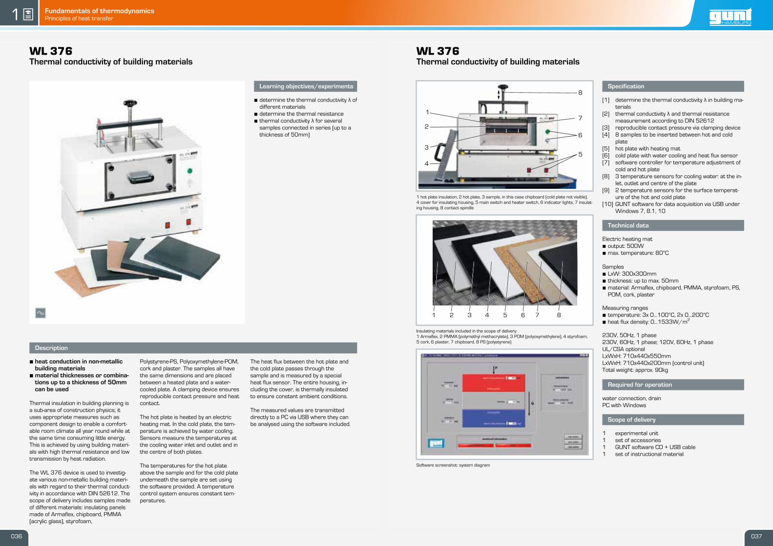
1 hot plate insulation, 2 hot plate, 3 sample, in this case chipboard (cold plate not visible),4 cover for insulating housing, 5 main switch and heater switch, 6 indicator lights, 7 insulat-ing housing, 8 contact spindle
Insulating materials included in the scope of delivery:1 Armaflex, 2 PMMA (polymethyl methacrylate), 3 POM (polyoxymethylene), 4 styrofoam,5 cork, 6 plaster, 7 chipboard, 8 PS (polystyrene)
Software screenshot: system diagram
Specification
[1] determine the thermal conductivity λ in building ma-terials
[2] thermal conductivity λ and thermal resistancemeasurement according to DIN 52612
[3] reproducible contact pressure via clamping device[4] 8 samples to be inserted between hot and cold
plate[5] hot plate with heating mat[6] cold plate with water cooling and heat flux sensor[7] software controller for temperature adjustment of
cold and hot plate[8] 3 temperature sensors for cooling water: at the in-
let, outlet and centre of the plate[9] 2 temperature sensors for the surface temperat-
ure of the hot and cold plate[10] GUNT software for data acquisition via USB under
Windows 7, 8.1, 10
Technical data
Electric heating mat• output: 500W• max. temperature: 80°C Samples• LxW: 300x300mm• thickness: up to max. 50mm• material: Armaflex, chipboard, PMMA, styrofoam, PS,
We reserve the right to modify our products without any notifications. Page 2/3 - 02.2018
guntWL 376Thermal conductivity of building materials
x
Description
• heat conduction in non-metallicbuilding materials
• material thicknesses or combina-tions up to a thickness of 50mmcan be used
Thermal insulation in building planning isa sub-area of construction physics; ituses appropriate measures such ascomponent design to enable a comfort-able room climate all year round while atthe same time consuming little energy.This is achieved by using building materi-als with high thermal resistance and lowtransmission by heat radiation.
The WL 376 device is used to investig-ate various non-metallic building materi-als with regard to their thermal conduct-ivity in accordance with DIN 52612. Thescope of delivery includes samples madeof different materials: insulating panelsmade of Armaflex, chipboard, PMMA(acrylic glass), styrofoam,
Polystyrene-PS, Polyoxymethylene-POM,cork and plaster. The samples all havethe same dimensions and are placedbetween a heated plate and a water-cooled plate. A clamping device ensuresreproducible contact pressure and heatcontact.
The hot plate is heated by an electricheating mat. In the cold plate, the tem-perature is achieved by water cooling.Sensors measure the temperatures atthe cooling water inlet and outlet and inthe centre of both plates.
The temperatures for the hot plateabove the sample and for the cold plateunderneath the sample are set usingthe software provided. A temperaturecontrol system ensures constant tem-peratures.
The heat flux between the hot plate andthe cold plate passes through thesample and is measured by a specialheat flux sensor. The entire housing, in-cluding the cover, is thermally insulatedto ensure constant ambient conditions.
The measured values are transmitteddirectly to a PC via USB where they canbe analysed using the software included.
Learning objectives/experiments
• determine the thermal conductivity λ ofdifferent materials
• determine the thermal resistance• thermal conductivity λ for several
samples connected in series (up to athickness of 50mm)
We reserve the right to modify our products without any notifications. Page 1/3 - 02.2018037036
1
2
3
8
6
5
7
4
81 2 3 4 5 6 7
Fundamentals of thermodynamicsPrinciples of heat transfer gunt1 gunt
WL 377Convection and radiation
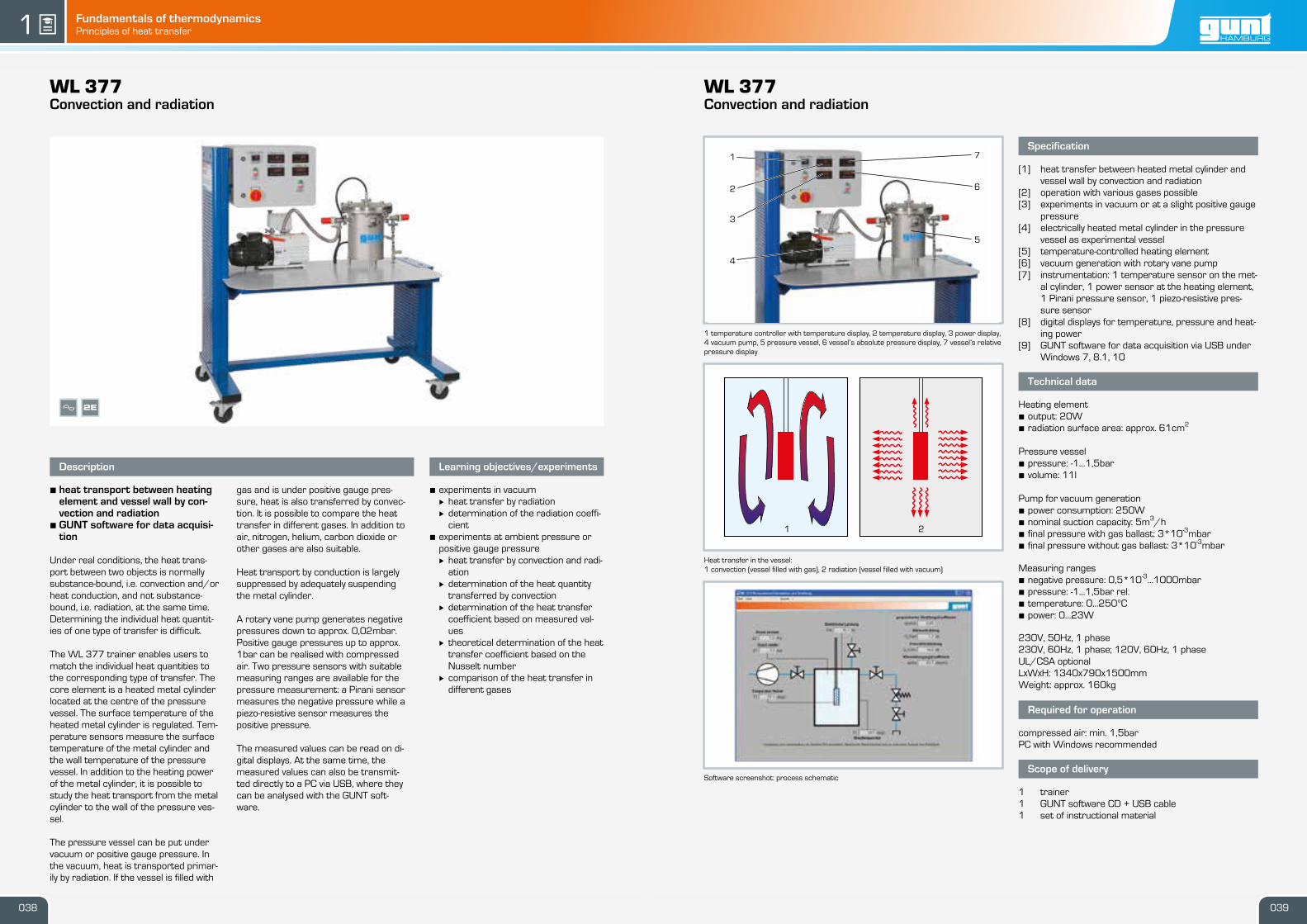
1 temperature controller with temperature display, 2 temperature display, 3 power display,4 vacuum pump, 5 pressure vessel, 6 vessel’s absolute pressure display, 7 vessel’s relativepressure display
Heat transfer in the vessel:1 convection (vessel filled with gas), 2 radiation (vessel filled with vacuum)
Software screenshot: process schematic
Specification
[1] heat transfer between heated metal cylinder andvessel wall by convection and radiation
[2] operation with various gases possible[3] experiments in vacuum or at a slight positive gauge
pressure[4] electrically heated metal cylinder in the pressure
vessel as experimental vessel[5] temperature-controlled heating element[6] vacuum generation with rotary vane pump[7] instrumentation: 1 temperature sensor on the met-
al cylinder, 1 power sensor at the heating element,1 Pirani pressure sensor, 1 piezo-resistive pres-sure sensor
[8] digital displays for temperature, pressure and heat-ing power
[9] GUNT software for data acquisition via USB underWindows 7, 8.1, 10
Pressure vessel• pressure: -1…1,5bar• volume: 11l Pump for vacuum generation• power consumption: 250W• nominal suction capacity: 5m3/h• final pressure with gas ballast: 3*10-3mbar• final pressure without gas ballast: 3*10-3mbar
We reserve the right to modify our products without any notifications. Page 2/2 - 03.2018
guntWL 377Convection and radiation
x 2E
Description
• heat transport between heatingelement and vessel wall by con-vection and radiation
• GUNT software for data acquisi-tion
Under real conditions, the heat trans-port between two objects is normallysubstance-bound, i.e. convection and/orheat conduction, and not substance-bound, i.e. radiation, at the same time.Determining the individual heat quantit-ies of one type of transfer is difficult.
The WL 377 trainer enables users tomatch the individual heat quantities tothe corresponding type of transfer. Thecore element is a heated metal cylinderlocated at the centre of the pressurevessel. The surface temperature of theheated metal cylinder is regulated. Tem-perature sensors measure the surfacetemperature of the metal cylinder andthe wall temperature of the pressurevessel. In addition to the heating powerof the metal cylinder, it is possible tostudy the heat transport from the metalcylinder to the wall of the pressure ves-sel.
The pressure vessel can be put undervacuum or positive gauge pressure. Inthe vacuum, heat is transported primar-ily by radiation. If the vessel is filled with
gas and is under positive gauge pres-sure, heat is also transferred by convec-tion. It is possible to compare the heattransfer in different gases. In addition toair, nitrogen, helium, carbon dioxide orother gases are also suitable.
Heat transport by conduction is largelysuppressed by adequately suspendingthe metal cylinder.
A rotary vane pump generates negativepressures down to approx. 0,02mbar.Positive gauge pressures up to approx.1bar can be realised with compressedair. Two pressure sensors with suitablemeasuring ranges are available for thepressure measurement: a Pirani sensormeasures the negative pressure while apiezo-resistive sensor measures thepositive pressure.
The measured values can be read on di-gital displays. At the same time, themeasured values can also be transmit-ted directly to a PC via USB, where theycan be analysed with the GUNT soft-ware.
Learning objectives/experiments
• experiments in vacuum· heat transfer by radiation· determination of the radiation coeffi-
cient• experiments at ambient pressure or
positive gauge pressure· heat transfer by convection and radi-
ation· determination of the heat quantity
transferred by convection· determination of the heat transfer
coefficient based on measured val-ues
· theoretical determination of the heattransfer coefficient based on theNusselt number
· comparison of the heat transfer indifferent gases
• adjust operating parameters via respective button icons
• check and read off measured values
Geometric temperature curve
• representations of the temperature curves make it easier to understand the respective heat trans-fer mechanisms
Time dependency
• representation of the measured values as a function of time
• plot and log your own characteristics
• freely selectable form of presentation of the measured values
· measured values selection
· resolution · colour · time intervals
WL 422 – v. 12.1.1.0gunt
WL 420 – Chart Recorder – v. 12.1.9gunt
EQUIPMENT FOR ENGINEERING EDUCATION
Overall didactic concept fortargeted teaching on the fundamentals of heat transfer.
• accurate measurements• software-controlled• training software
The series for a simple introduction to a complex subject.
Thermoline Fundamentals of Heat Transfer
Fundamentals of thermodynamicsPrinciples of heat transfer gunt1 gunt
WL 420Heat conduction in metals
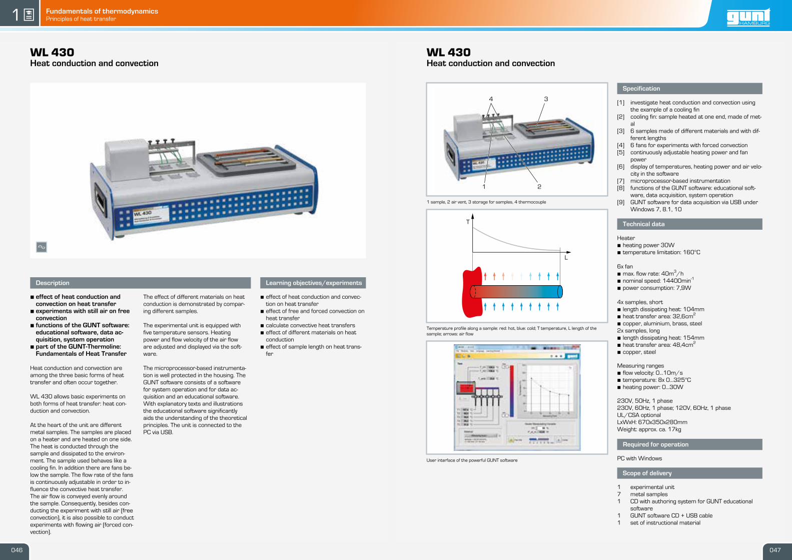
1 heater, 2 sample, 3 storage for samples, 4 thermocouple; Peltier element concealed
Heat conduction through different metals: 1 temperature profile in metal with low thermalconductivity, 2 temperature profile in metal with medium thermal conductivity, 3 temperat-ure profile in metal with high thermal conductivity; T temperature; red: hot, blue: cold
User interface of the powerful GUNT software
Specification
[1] investigation of the thermal conductivity of differentmetals
[2] continuously adjustable heater[3] Peltier element as cooler[4] 11 samples made of 5 metals, different lengths[5] display of temperatures and power consumption in
the software[6] microprocessor-based instrumentation[7] functions of the GUNT software: educational soft-
ware, data acquisition, system operation[8] GUNT software for data acquisition via USB under
Windows 7, 8.1, 10
Technical data
Peltier element• cooling capacity 56,6W Heater• heating power 30W• temperature limitation: 150°C Samples Ø 20mmLength between measuring points• 5x 20mm (copper, steel, stainless steel, brass, alu-
We reserve the right to modify our products without any notifications. Page 2/3 - 03.2018
guntWL 420Heat conduction in metals
x
Description
• effect of different metals on heatconduction
• functions of the GUNT software:educational software, data ac-quisition, system operation
• part of the GUNT-Thermoline:Fundamentals of Heat Transfer
Heat conduction is one of the three ba-sic forms of heat transfer. According tothe second law of thermodynamics, heatis always transferred from the higherenergy level to the low energy level. If thetemperature of a body does not changedespite continuous addition or removalof heat, this is known as steady-stateheat conduction.
WL 420 offers basic experiments fortargeted teaching on the topic of heatconduction through various metals. Tothis end, one of eleven samples is used.The upper region of the sample isheated by an electrical heater and thelower section cooled by a Peltier ele-ment. Heat conduction occurs throughthe respective sample from top to bot-tom. Two samples can be inserted intothe experimental unit at the same time,in order to investigate thermal conduct-ivity through multi-layered metals. Per-fectly matched components ensure rap-id heating and trouble-free measure-ments.
The temperature of the metal samplesis taken on the top and bottom bymeans of thermocouples. The micropro-cessor-based instrumentation is wellprotected in the housing. The GUNTsoftware consists of a software for sys-tem operation and for data acquisitionand an educational software. With ex-planatory texts and illustrations the edu-cational software significantly aids theunderstanding of the theoretical prin-ciples. The unit is connected to the PCvia USB.
Learning objectives/experiments
• time dependency until the steady stateis reached
• calculate the thermal conductivity λ ofdifferent metals
• calculate the thermal resistance of thesample
• heat transfer with different samplesconnected in series
We reserve the right to modify our products without any notifications. Page 2/3 - 02.2018
guntWL 422Heat conduction in fluids
x
Description
• effect of different fluids on heatconduction
• functions of the GUNT software:educational software, data ac-quisition, system operation
• part of the GUNT-Thermoline:Fundamentals of Heat Transfer
Heat conduction is one of the three ba-sic forms of heat transfer. According tothe second law of thermodynamics, heatis always transferred from the higherenergy level to the low energy level.
WL 422 offers basic experiments fortargeted teaching on the topic of heatconduction in fluids. Such teachingshould discuss the fundamental differ-ences between gases and liquids.
Two cylinders form the main componentof the experimental unit: an electricallyheated inner cylinder situated in a water-cooled outer cylinder. There is a con-centric annular gap between the two cyl-inders. This annular gap is filled with thefluid being studied. The heat conductionoccurs from the inner cylinder, throughthe fluid to the outer cylinder.
The narrow annular gap prevents theformation of a convective heat flux andallows a relatively large pass-througharea while at the same time providing ahomogeneous temperature distribution.
The experimental unit is equipped withtemperature sensors inside and outsideof the annular gap. Thermal conductivit-ies for different fluids, e.g. water, oil, airor carbon dioxide can be determined inexperiments.
The microprocessor-based instrumenta-tion is well protected in the housing. TheGUNT software consists of a softwarefor system operation and for data ac-quisition and an educational software.With explanatory texts and illustrationsthe educational software significantlyaids the understanding of the theoreticalprinciples. The unit is connected to thePC via USB.
Learning objectives/experiments
• steady heat conduction in gases and li-quids:· determine the thermal resistance of
fluids· determination of thermal conductivit-
ies k for different fluids at differenttemperatures
• transient heat conduction in fluids:· interpret transient states during
heating and cooling· introduction to transient heat con-
We reserve the right to modify our products without any notifications. Page 2/3 - 02.2018
guntWL 430Heat conduction and convection
x
Description
• effect of heat conduction andconvection on heat transfer
• experiments with still air on freeconvection
• functions of the GUNT software:educational software, data ac-quisition, system operation
• part of the GUNT-Thermoline:Fundamentals of Heat Transfer
Heat conduction and convection areamong the three basic forms of heattransfer and often occur together.
WL 430 allows basic experiments onboth forms of heat transfer: heat con-duction and convection.
At the heart of the unit are differentmetal samples. The samples are placedon a heater and are heated on one side.The heat is conducted through thesample and dissipated to the environ-ment. The sample used behaves like acooling fin. In addition there are fans be-low the sample. The flow rate of the fansis continuously adjustable in order to in-fluence the convective heat transfer.The air flow is conveyed evenly aroundthe sample. Consequently, besides con-ducting the experiment with still air (freeconvection), it is also possible to conductexperiments with flowing air (forced con-vection).
The effect of different materials on heatconduction is demonstrated by compar-ing different samples.
The experimental unit is equipped withfive temperature sensors. Heatingpower and flow velocity of the air floware adjusted and displayed via the soft-ware.
The microprocessor-based instrumenta-tion is well protected in the housing. TheGUNT software consists of a softwarefor system operation and for data ac-quisition and an educational software.With explanatory texts and illustrationsthe educational software significantlyaids the understanding of the theoreticalprinciples. The unit is connected to thePC via USB.
Learning objectives/experiments
• effect of heat conduction and convec-tion on heat transfer
• effect of free and forced convection onheat transfer
• calculate convective heat transfers• effect of different materials on heat
conduction• effect of sample length on heat trans-
We reserve the right to modify our products without any notifications. Page 1/3 - 02.2018047046
T
L
1 2
4 3
Fundamentals of thermodynamicsPrinciples of heat transfer gunt1 gunt
WL 440Free and forced convection
1 fan, 2 sight window, 3 air inlet, 4 hand-held meter for temperature, 5 heating element
Various interchangeable heating elements: 1 tube bundle, 2 plane plate, 3 cylinder withheating foil to examine the local heat transfer, 4 cylinder with an even temperature at thesurface
User interface of the powerful GUNT software
Specification
[1] investigate heat transfer in the air duct by forcedconvection
[2] study of free convection[3] air duct with axial fan[4] 4 heating elements with different geometries[5] continuously adjustable heating power and fan
power[6] display of temperatures, heating power and air velo-
city in the software[7] microprocessor-based instrumentation[8] functions of the GUNT software: educational soft-
ware, data acquisition, system operation[9] GUNT software for data acquisition via USB under
Windows 7, 8.1, 10
Technical data
Air duct• flow cross-section: 120x120mm• height: approx. 0,6mHeating elements, temperature limitation: 90°C• tube bundle· number of tubes: 23· one tube in variable postion is heated· heating power: 20W· heat transfer area: 0,001m2
• cylinder with an even temperature at the surface· heating power: 20W· heat transfer area: 0,0112m2
• plate· heating power: 40W· heat transfer area: 2x 0,01m2
• cylinder with heating foil to investigate the local heattransfer· heating power: 40W· heat transfer area: 0,0112m2
We reserve the right to modify our products without any notifications. Page 2/3 - 02.2018
guntWL 440Free and forced convection
x
Description
• free and forced convection usingthe example of various heatingelements
• functions of the GUNT software:educational software, data ac-quisition, system operation
• part of the GUNT-Thermoline:Fundamentals of Heat Transfer
Convection is one of the three basicforms of heat transfer. Material-boundheat transport takes place. During con-vection the fluid is in motion.
The WL 440 offers basic experimentsfor targeted teaching on the topic offree and forced convection on variousheating elements.
At the heart of the experimental unit is avertical air duct into which various heat-ing elements are inserted.
An axial fan is located on top of the airduct. The fan draws in ambient air andguides it through the air duct. The airflows past a heating element and ab-sorbs heat. Four heating elements withdifferent geometries are available to beselected. In order to investigate freeconvection, two of the four heating ele-ments can be operated outside of theair duct. The heating elements are de-signed in such a way to release heat onlyat their surface. The compact design en-sures rapid heating and a short time forexperiments.
The experimental unit is equipped withtemperature sensors at the inlet andoutlet of the air duct. The air velocity ismeasured to determine the air flow rate.Heating power and flow rate are adjus-ted and displayed via the software.
The microprocessor-based instrumenta-tion is well protected in the housing. TheGUNT software consists of a softwarefor system operation and for data ac-quisition and an educational software.With explanatory texts and illustrationsthe educational software significantlyaids the understanding of the theoreticalprinciples. The unit is connected to thePC via USB.
Learning objectives/experiments
• free and forced convection• calculation of convective heat transfer
at different geometries· flat plate· cylinder· tube bundle
• experimental determination of the Nus-selt number
• calculation of typical characteristicvariables of heat transfer· Nusselt number· Reynolds number
• investigation of the relationshipbetween flow formation and heattransfer during experiments
We reserve the right to modify our products without any notifications. Page 2/3 - 02.2018
guntWL 460Heat transfer by radiation
x
Description
• effect of different surfaces onheat transfer by radiation
• functions of the GUNT software:educational software, data ac-quisition, system operation
• part of the GUNT-Thermoline:Fundamentals of Heat Transfer
Heat radiation is one of the three basicforms of heat transfer. In radiation theheat transfer takes place via electro-magnetic waves. Unlike heat conductionand convection, heat radiation can alsopropagate in a vacuum. Heat radiation isnot bound to a material.
WL 460 offers basic experiments fortargeted teaching on the topic of heattransfer by radiation. At the heart of theexperimental unit is a metallic sampleheated by a concentrated light beam.The light beam is generated by a con-tinuously adjustable halogen lamp and aparabolic reflector. The reflector con-centrates the radiation to a focal point.A sample is placed on a thermocouplelocated at the focal point. The thermalradiation emitted by the sample is meas-ured by a thermopile. In order to be ableto measure the radiation at different dis-tances, the thermopile is mounted on amoveable carriage.
Samples with different surfaces areavailable to be selected. Perfectlymatched components ensure rapidheating and trouble-free measurements.
The microprocessor-based instrumenta-tion is well protected in the housing. TheGUNT software consists of a softwarefor system operation and for data ac-quisition and an educational software.With explanatory texts and illustrationsthe educational software significantlyaids the understanding of the theoreticalprinciples. The unit is connected to thePC via USB.
Learning objectives/experiments
• verify Lambert’s inverse-square law• verify Stefan-Boltzmann law• verify Kirchhoff’s law• study transient behaviour• create power balances• produce logarithmic diagrams for eval-
We reserve the right to modify our products without any notifications. Page 1/3 - 02.2018051050
1
2
3
5
4
I
L
Fundamentals of thermodynamicsPrinciples of heat transfer gunt1 gunt
WL 900Steady-state and non-steady-state heat conduction
1 elevated tank for constant cooling water initial pressure, 2 heat source with heater,3 sample, 4 water-cooled heat sink, 5 displays and controls
1 heater, 2 sample, 3 heat sink; T temperature, Q flow rate, TC heating water temperaturecontroller, Pel electric heating power, blue cooling water, red heating water
Transient temperature profile along a rod with sudden coolingT temperature, L length of the rod, coloured lines: temperature profile at different points intime
Specification
[1] investigation of steady and transient heat conduc-tion in metals
[2] determining the thermal conductivity λ[3] heating water circuit as heat source, electronically
regulated[4] electric heater with PID controller[5] elevated tank with overflow for generating a con-
stant cooling water flow rate[6] samples made of 5 different metals[7] cooling water temperature and flow rate measure-
ment[8] digital displays: electric heating power, temperat-
ures, cooling water flow rate[9] GUNT software for data acquisition via USB under
Windows 7, 8.1, 10
Technical data
Heater• output: 800W• temperature: 20…85°C Samples, Ø 40mm• 3x 450mm (copper, aluminium, brass)• 2x 300mm (steel, stainless steel) Heating tank: ca. 2LCooling tank: ca. 0,5LElevated tank: ca. 6L Temperature sensors• 12x thermocouple type K, along the sample• 2x Pt100, in the cooling water• 1x Pt100, in the heating water
We reserve the right to modify our products without any notifications. Page 2/2 - 03.2018
guntWL 900Steady-state and non-steady-state heat conduction
x
Description
• steady and transient heat con-duction in metals
• 12 temperature measurementpoints in every sample
• regulated temperature of theheat source
Heat conduction is the transport of heatbetween the individual molecules in solid,liquid and gaseous media under the influ-ence of a temperature difference.Steady heat conduction is the term usedwhen heat transport is maintained per-manently and uniformly by adding heat.In transient heat conduction, the tem-perature distribution in the body is de-pendent on location and time.
Thermal conductivity λ is a temperature-dependent property of a material that in-dicates how well the heat propagatesfrom a point in the material.
WL 900 can be used to study bothsteady and transient heat conduction.The trainer consists of a heat sourceand a heat sink, between which cylindric-al samples made of different metals areinserted. Each sample is fitted with 12temperature measurement points. Thetemperature measurement points aredesigned to has as little influence on thetemperature as possible and the coretemperature of the sample is meas-ured.
The heat source consists of an electric-ally heated hot water circuit. An elec-tronic controller ensures the heatingwater is kept at a constant temperature.The heat sink is realised by means of awater cooling system. An elevated tankensures a constant cooling water flowrate.
A temperature jump can be generatedby appropriate regulation of the coolingwater flow. A PC can be used to displaythe transient temperature distribution inthe sample over time and place.
The temperatures of the sample, heat-ing and cooling water, as well as theelectrical heating power and the coolingwater flow rate are displayed digitally onthe switch cabinet and can be transmit-ted simultaneously via USB directly to aPC where they can be analysed usingthe software included. The thermal con-ductivity λ can be calculated from themeasured data.
We reserve the right to modify our products without any notifications. Page 1/2 - 03.2018053052
1
2
3
5
4
T
2
3
1
TC
Q T
Pel
T
T
T
T
T
20s50s
100s200s400s
1000s
70
60
50
40
30
20
10
0L
T in
C°
Basic knowledge
Phase transition
Fundamentals of thermodynamicsPhase transition gunt1
Phase transition Evaporation process
Steam is used for a variety of processes in engineering. The most common applications are heating processes as well as steam turbines in power plants.
Typical applications of steam in processes include:
• heating: e.g. shell-and-tube heat exchangers to heat up a product
• propulsion: e.g. steam turbines, steam engines
• propellant: e.g. steam ejectors to separate process gases
• atomization: steam for the mechanical separation of fluids, e.g. in gas flares, to reduce soot particles in the exhaust gas
• cleaning: steam cleaners to loosen dirt
• product moistening: paper production
• air humidification: steam humidifiers in air ducts
We distinguish between ideal gas, real gas and vapour. In an ideal gas, pressure and volume are exactly inversely proportional, in a real gas only by approximation. In vapours, the pressure changes only slightly with the volume, depending on the degree of saturation.
Steam occurs in various forms:
Wet steam: Liquid and gaseous state of the water molecules in a system, some water molecules have released their evapora-tion heat and condense into fine water droplets.
Saturated steam: Boundary area between wet steam and hot steam, state in which the last drop of water changes from liquid to gaseous. The addition of further heat beyond the boiling point produces hot steam or superheated steam.
Hot steam: A distinction is made between superheated steam and supercritical steam.
Superheated steam: Steam with a temperature above the boil-ing temperature, purely gaseous state of the water molecules. Real gas is present.
Supercritical steam: Phase at temperatures above the critical point
gaseous
solid
melting
solidificationliquid
sublim
ation
desublim
ation
evaporationcondensation
A gaseous, liquid or solid state in a homogeneous sys-tem of substances is called a phase. The phase depends on the thermodynamic state variables pressure p and temper-ature T.
The conversion from one phase to another is called a phase transition:
water
vapour
ice
100 200 300 3740
102
10
1
10-1
10-2
10-3
2213
2
1
p in
bar
T in °C
Above the critical point 3 the gaseous and liquid phases of some systems of substances, e. g. water, cannot be differen-tiated anymore. The physical properties of the fluid lie some-where between the two phases: The density corresponds to the density of the liquid phase, the viscosity to that of the gaseous phase. This phase is known as the “supercritical” phase. In this phase, the fluid can neither evaporate nor condense.
Another particularity in some systems of substances, such as water, is known as the triple point 1 . At this point the solid, liquid and gaseous phase are in equilibrium. All six phase changes occur simultaenously.
Closed system along the vapour pressure curve of water
vaporisation curve, water, vapour;
p pressure, T temperature
In a closed system filled with liquid, a thermodynamic equilibra-tion sets in between the liquid and its vaporised phase. This state is called the saturation state. The prevailing pressure is referred to as vapour pressure, in case of water steam pressure or saturated steam pressure, and the temperature is known as saturation temperature. The vapour pressure curve can be derived from both. This curve is shown in the phase diagram of water.
T in °C
p in bar
221,285,88
15,55
1,013
0,023
20 100 200 300 374
T
v
1
2 43
5p=1barT=99,6°C
p=1bar
p p
p
liquid boiling liquid
wet steam
saturated steam
superheated steam = gas
1 2 3 4 5
heating evaporation superheating
pp
Evaporation of water: change of state when heating water under constant pressure p = 1bar
T temperature, v specific volume; 1 liquid, 2 boiling liquid, 3 unsaturated (wet) steam, 4 saturated steam, 5 superheated steam (gas)
055054
Fundamentals of thermodynamicsPhase transition gunt1 gunt
Evaporation in a tube evaporator:A subcooled fluid, B initial boiling point, C bubbly flow, D slug flow, E annular flow, F dispersedflow, G superheated vapour, H boiling range; blue: fluid temperature, grey: heating surfacetemperature
Specification
[1] visualisation of evaporation in a tube evaporator[2] heating and cooling medium: water[3] tube evaporator made of double-wall glass[4] heating circuit with heater, pump and expansion
vessel[5] safety valve protects against overpressure in the
system[6] water jet pump to evacurate the evaporation circuit
generate negative pressure (vacuum)[7] evaporation circuit with CFC-free evaporating liquid
Solkatherm SES36
Technical data
Heater• power rating: 2kW• temperature range: 5…80°CHeating and cooling medium: water Pump• 3 stages• max. flow rate: 1,9m3/h• max. head: 1,5m• power consumption: 58W Tube evaporator• length: 1050mm• inner diameter: 16mm• outer diameter: 24mm Condenser: coiled tube made of copper
We reserve the right to modify our products without any notifications. Page 2/2 - 02.2018
guntWL 210Evaporation process
Description
• demonstration of evaporation in adouble-wall pipe evaporator madeof glass
• operation with harmless, speciallow boiling point liquid
During the generation of vapour, the me-dium that is to evaporate runs throughdifferent flow forms dependent on theheat transfer area. The medium flows in-to a tube evaporator as a fluid and exitsthe tube evaporator as superheated va-pour.
In practice, the water vapour generatedin big systems is used e.g. for heatingplants or machine drives. To designsteam generators, it is important tohave knowledge of the evaporation pro-cess with the boiling crises in order toensure reliable operation. Boiling crisesare caused by a sudden deterioration ofthe heat transfer, whereby the high heatflux density leads to a dangerous in-crease in the wall temperature.
The WL 210 experimental unit can beused to examine and visualise the evap-oration process in its various flow forms.This is done by heating evaporating li-quid, Solkatherm SES36, in a tube evap-orator made of glass.
Compared with water, this liquid has theadvantage that its boiling point is at36,7°C (1013hPa), whereby the entireevaporation process takes place atmuch lower temperatures and a lowerheating power. The pressure can be var-ied via the cooling circuit. A water jetpump evacurates the evaporation cir-cuit.
Learning objectives/experiments
• observation of typical forms of evapor-ation· single phase liquid flow· sub-cooled boiling· slug flow· annular flow· film boiling· dispersed flow· single phase vapour flow· wet steam
• effect on the evaporation process by· flow rate· temperature· pressure
We reserve the right to modify our products without any notifications. Page 1/2 - 02.2018057056
1
2
3
4
5
6
11
10
9
8
7
T A
H
B
C
D
E
F
G
Fundamentals of thermodynamicsPhase transition gunt1 gunt
WL 220Boiling process
1 safety valve, 2 displays for temperature, flow rate and pressure, 3 condenser, 4 pressurevessel, 5 drain valve for the evaporating liquid, 6 heater, 7 cooling water connection, 8 valvefor adjusting the cooling water, 9 cooling water flow rate sensor
1 pressure vessel, 2 heater, 3 drain valve, 4 cooling water valve, 5 safety valve, 6 condens-er; orange: evaporating liquid, red: heater, blue: cooling circuit; PSL pressure switch, E out-put, T temperature, Q flow rate, P pressure
Different modes of boiling: A free convection boiling, B nucleate boiling, C film boiling;red: heater, blue: evaporating liquid, white: steam, black: convection flow
Specification
[1] visualisation of boiling and evaporation in a trans-parent pressure vessel
[2] evaporation with heating element[3] condensation with tube coil[4] safety valve protects against overpressure in the
system[5] pressure switch for additional protection of the
pressure vessel, adjustable[6] sensors for pressure, flow rate and temperature
with digital display[7] GUNT software for data acquisition via USB under
Windows 7, 8.1, 10[8] CFC-free evaporating liquid Solkatherm SES36
Technical data
Heater• power: 250W, continuously adjustable Safety valve: 2bar rel.Pressure vessel: 2850mLCondenser: coiled tube made of copper
Measuring ranges• tank pressure: 0…4bar abs.• power of heater: 0…300W• flow rate (cooling water): 0,05…1,8L/min• temperature: 4x 0…100°C
We reserve the right to modify our products without any notifications. Page 2/3 - 03.2018
guntWL 220Boiling process
x
Description
• visualisation of boiling and evap-oration
• software for data acquisition
Heating a liquid over a heating surfaceproduces different modes of boiling de-pendent on the heat flux density. Theycan accelerate the evaporation process(nucleate boiling) or impair it (film boil-ing). In practice, a limitation of the heatflux density must be assured in order toprevent damage to the heating surface.This knowledge is applied in practice e.g.when designing steam boilers for steam-powered drives.
The WL 220 experimental unit can beused to demonstrate boiling and evapor-ation processes in a straightforwardmanner. The processes take place in atransparent tank. A condenser in theform of a water-cooled tube coil ensuresa closed circuit within the tank. Solk-atherm SES36 is used as evaporating li-quid. Compared with water, this liquidhas the advantage that its boiling pointis at 36,7°C (1013hPa), whereby theevaporation process takes place atmuch lower temperatures and a lowerheating power.
Sensors record the flow rate of the cool-ing water, the heating power, pressureand temperatures at all relevant points.The measured values can be read on di-gital displays. At the same time, themeasured values can also be transmit-ted directly to a PC via USB. The dataacquisition software is included.
Learning objectives/experiments
• visualisation of different forms of evap-oration· free convection boiling· nucleate boiling· film boiling
• heat transfer• effect of temperature and pressure on
We reserve the right to modify our products without any notifications. Page 1/3 - 03.2018059058
1
2 3
5
6
4
P
E
T
T
TT
Q
PSL
9
8
1
2
3
4
5 6
7
A B C
Fundamentals of thermodynamicsPhase transition gunt1 gunt
WL 204Vapour pressure of water - Marcet boiler
1 safety valve, 2 pressure boiler with insulating jacket, 3 Bourdon tube pressure gauge,4 switch cabinet with temperature display, 5 drain valve, 6 heater, 7 overflow,8 temperature sensor
Heating up water in a closed tank: the pressure and temperature increase proportionally upto the critical point, at which fluid and vapour are no longer distinguishable from each other;critical point at Tc=374°C, pc=221bar, dotted line: temperature limit of the experimentalunit
Temperature-pressure diagram of waterred: sublimation curve, green: boiling point curve, blue: melting point curve; 1 triple point,2 boiling point, 3 critical point
Specification
[1] measuring a vapour pressure curve for saturatedvapour
[2] pressure boiler with insulating jacket[3] temperature limiter and safety valve protect
against overpressure in the system[4] Bourdon tube pressure gauge to indicate pressure[5] digital temperature display
We reserve the right to modify our products without any notifications. Page 2/3 - 03.2018
guntWL 204Vapour pressure of water - Marcet boiler
Description
• recording the vapour pressurecurve of water
• saturation pressure of water va-pour as a function of the temper-ature
In a closed system filled with fluid, a ther-modynamic equilibrium sets in betweenthe fluid and its vaporised phase. Theprevailing pressure is called vapourpressure. It is substance-specific andtemperature-dependent.
When a fluid is heated in a closed tank,the pressure increases as the temperat-ure rises. Theoretically, the pressure in-crease is possible up to the critical pointat which the densities of the fluid andgaseous phases are equal. Fluid and va-pour are then no longer distinguishablefrom each other. This knowledge is ap-plied in practice in process technologyfor freeze drying or pressure cooking.
The WL 204 experimental unit can beused to demonstrate the relationshipbetween the pressure and temperatureof water in a straightforward manner.Temperatures of up to 200°C are pos-sible for recording the vapour pressurecurve. The temperature and pressurecan be continuously monitored via a di-gital temperature display and a Bourdontube pressure gauge.
A temperature limiter and pressure re-lief valve are fitted as safety devices andprotect the system against overpres-sure.
Learning objectives/experiments
• recording the vapour pressure curveof water
• presentation of the relationshipbetween pressure and temperature ina closed system
We reserve the right to modify our products without any notifications. Page 1/3 - 03.2018061060
20
°C
10
0°C
20
0°C
30
0°C
37
0°C
37
4°C
T C
0,0
23
bar
1,0
13
bar
15
,55
bar
85
,88
bar
21
0,4
bar
22
1,2
bar
p C
1
210
-210
-310
10
-110
0 100 200 300 374
T in °C
p in
bar
221
ice
vapour
water
1
2
3
12
3
4
5
6
7
8
Fundamentals of thermodynamicsPhase transition gunt1 gunt
WL 230Condensation process
1 condensers, 2 heat exchanger, 3 steam trap, 4 displays for temperature, flow rate andpressure, 5 heater, 6 cooling water connections, 7 water jet pump, 8 temperature sensor,9 valve for adjusting the cooling water, 10 cooling water flow rate sensor
Software screenshot
Vapour pressure curve for water: p pressure, T temperature
Specification
[1] visualisation of the condensation process of waterin a transparent tank
[2] two water-cooled tubes as condensers with differ-ent surfaces to realise film condensation and drop-wise condensation
[3] controlled heater to adjust the boiling temperature[4] water jet pump to evacuate the tank[5] pressure switch and safety valve for safe operation[6] sensors for temperature, pressure and flow rate
with digital display[7] GUNT software for data acquisition via USB under
Windows 7, 8.1, 10
Technical data
Heater• output: 3kW, freely adjustable Condenser• 1x tube with matt copper surface• 1x tube with a polished gold-plated surface Water jet pump• flow rate: 4…12L/min• pressure: 16mbar Safety valve: 2200mbar absolute
We reserve the right to modify our products without any notifications. Page 2/3 - 02.2018
guntWL 230Condensation process
x
Description
• visualisation of different condens-ation processes
• software for data acquisition
Condensation forms when steam meetsa medium with a lower temperaturethan the saturation temperature for theexisting partial pressure of the steam.Factors such as the material and sur-face roughness of the medium influencethe heat transfer and thus the type ofcondensation. In practice, it is usuallyfilm condensation. Dropwise condensa-tion only forms when the cooling surfaceis very smooth and poorly wettable, e.g.Teflon. Knowledge of condensation pro-cesses is applied e.g. in steam powerplants or at distillation processes.
The WL 230 experimental unit can beused to demonstrate the different con-densation processes using two tubularshaped water-cooled condensers madeof different materials. Dropwise con-densation can be demonstrated bymeans of the condenser with a polishedgold-plated surface. Film condensationforms on the matt copper surface of thesecond condenser, thus making it pos-sible to examine film condensation.
The tank can be evacuated via a waterjet pump. The boiling point and the pres-sure in the system are varied by coolingand heating power. Sensors record thetemperature, pressure and flow rate atall relevant points. The measured valuescan be read on digital displays. At thesame time, the measured values canalso be transmitted directly to a PC via USB. The data acquisition software is in-cluded. The heat transfer coefficient iscalculated from the measured values.The influence of non-condensing gases,pressure and the temperature differ-ence between the surface and steamcan be examined in further experiments.
Learning objectives/experiments
• dropwise and film condensation• determination of the heat transfer
coefficient• effect of pressure, temperature and
non-condensable gases on the heattransfer coefficient