150
GV Series Automated Dispensing Systems Operating Manual for Gantry Robots ™ Electronic pdf files of Nordson EFD manuals are also available at www.nordsonefd.com
GV Series Automated Dispensing SystemsOperating Manual for Gantry Robots
™
Electronic pdf files of Nordson EFD manuals are also available at www.nordsonefd.com

GV Series Automated Dispensing Systems
2 www.nordsonefd.com [email protected] +1-401-431-7000 Sales and service of Nordson EFD dispensing systems are available worldwide.
You have selected a reliable, high-quality dispensing system from Nordson EFD, the world leader in fluid dispensing. Nordson EFD automated dispensing systems are designed specifically for industrial dispensing and will provide you with years of trouble-free, productive service.
This manual will help you maximize the usefulness of your automated dispensing system.
Please spend a few minutes to become familiar with the controls and features. Follow our recommended testing procedures. Review the helpful information we have included, which is based on more than 50 years of industrial dispensing experience.
Most questions you will have are answered in this manual. However, if you need assistance, please do not hesitate to contact EFD or your authorized EFD distributor. Detailed contact information is provided on the last page of this document.
The Nordson EFD Pledge
Thank You!
You have just purchased the world’s finest precision dispensing equipment.
I want you to know that all of us at Nordson EFD value your business and will do everything in our power to make you a satisfied customer.
If at any time you are not fully satisfied with our equipment or the support provided by your Nordson EFD Product Application Specialist, please contact me personally at 800.556.3484 (US), 401.431.7000 (outside US), or [email protected].
I guarantee that we will resolve any problems to your satisfaction.
Thanks again for choosing Nordson EFD.
Tara Tereso, Vice PresidentTara
GV Series Automated Dispensing Systems
3www.nordsonefd.com [email protected] +1-401-431-7000 Sales and service of Nordson EFD dispensing systems are available worldwide.
Contents ..........................................................................................................................................................................3Introduction .....................................................................................................................................................................6Nordson EFD Product Safety Statement ........................................................................................................................7
Halogenated Hydrocarbon Solvent Hazards ...............................................................................................................8High Pressure Fluids ....................................................................................................................................................8Qualified Personnel ......................................................................................................................................................8Intended Use ...............................................................................................................................................................9Regulations and Approvals ..........................................................................................................................................9Personal Safety ............................................................................................................................................................9Fire Safety ..................................................................................................................................................................10Preventive Maintenance ............................................................................................................................................10Important Disposable Component Safety Information ..............................................................................................11Action in the Event of a Malfunction ..........................................................................................................................11Disposal .....................................................................................................................................................................11Equipment-Specific Safety Information .....................................................................................................................12
Specifications ................................................................................................................................................................13Operating Features ........................................................................................................................................................15
G4V Series System Component Identification ..........................................................................................................15G8V Series System Component Identification ..........................................................................................................16GV Operation Box ......................................................................................................................................................17Start / Stop Box .........................................................................................................................................................18Camera ......................................................................................................................................................................18
Installation .....................................................................................................................................................................19Unpack the System Components ..............................................................................................................................19Position the Robot and Install and Connect Components ........................................................................................20Check the Camera and Dispenser Installation ..........................................................................................................22Prepare the Work Surface .........................................................................................................................................23Connect Inputs / Outputs (Optional) ..........................................................................................................................24Power On the System ................................................................................................................................................25
Concepts .......................................................................................................................................................................26About Programs and Commands ..............................................................................................................................26About Offsets .............................................................................................................................................................27About Marks ..............................................................................................................................................................28
Overview of the DispenseMotion Software ...................................................................................................................29Command Windows ..................................................................................................................................................30Primary View Screen and Tab Bar .............................................................................................................................31Primary View Screen Right-Click Functions ..............................................................................................................32Secondary View Screen .............................................................................................................................................33Secondary View Screen in Path View ........................................................................................................................34Horizontal and Vertical Toolbar Icons ........................................................................................................................35Setup and Dispense Command Icons .......................................................................................................................36Navigation and Jogging Window ...............................................................................................................................37System Setup Screen ................................................................................................................................................39Camera Screen, Tab Bar, and Icons .........................................................................................................................40Camera Properties Window .......................................................................................................................................41Template Match and Area Windows..........................................................................................................................42Camera Setup Screen ...............................................................................................................................................43Keypad .......................................................................................................................................................................43
Continued on next page
Contents
GV Series Automated Dispensing Systems
4 www.nordsonefd.com [email protected] +1-401-431-7000 Sales and service of Nordson EFD dispensing systems are available worldwide.
Setup .............................................................................................................................................................................44Setting System Parameters .......................................................................................................................................44Setting Password Protection .....................................................................................................................................47Setting Up and Calibrating the System (Required) ....................................................................................................48
Verifying the Robot Model and Tip Detector Selection ..........................................................................................48Setting Up the System Using the Robot Initial Setup Wizard ................................................................................49(Only Systems Without a Tip Detector) Testing the System Setup and Calibration ..............................................56How the System Responds to Needle Z Detect or Needle XY Adjust ...................................................................57Changing the Robot Model Selection ....................................................................................................................57
Setting Up Inputs / Outputs .......................................................................................................................................58Configuring Input / Outputs for a Special Purpose ...................................................................................................58Setting How the System Finds Marks (Optional) .......................................................................................................59Setting How the System Captures Z Height Values (Optional) .................................................................................60Sharing Offset Values Across Multiple Programs ......................................................................................................61Setting the Units of Measure .....................................................................................................................................62Restoring the System to the Factory Default Settings ..............................................................................................62
Programming .................................................................................................................................................................63How to Create and Run a Program ...........................................................................................................................63How to Add Comments to a Program .......................................................................................................................64How to Lock or Unlock a Program ............................................................................................................................65How to Measure a Path or Circle on a Workpiece ....................................................................................................65How to Create Patterns .............................................................................................................................................66
Dispense Dot Sample Program ..............................................................................................................................66Lines and Arcs Sample Program ...........................................................................................................................66Circle Sample Program ..........................................................................................................................................67
How to Use the Example Icon ...................................................................................................................................67How to Dispense on Multiple Workpieces in an Array ..............................................................................................68How to Disable Dispensing for Specific Workpieces in an Array ..............................................................................69How to Create a Mark ................................................................................................................................................70How to Improve the Accuracy of Mark Searches ......................................................................................................71How to Use Marks or Fiducial Marks in a Program ...................................................................................................72How to Use Marks to Dispense onto a Plain Workpiece ...........................................................................................73How to Use Mark Follow to Dispense Along a Curved Line ......................................................................................76How to Set Up Auto Purge, Program Cycle Limits, or Fluid Working Life Limits ......................................................82How to Use Point Offset to Adjust All Points in a Program .......................................................................................83How to Adjust PICO Parameters Using DispenseMotion ..........................................................................................84
Operation .......................................................................................................................................................................87Starting the System and Running a Program ............................................................................................................87Performing an Emergency Stop.................................................................................................................................87About the RUN / TEACH Switch ................................................................................................................................87Running a Program by Scanning a QR Code ............................................................................................................88Pausing During a Dispense Cycle..............................................................................................................................88Purging the System ...................................................................................................................................................88Updating Offsets ........................................................................................................................................................88Shutting Down the System ........................................................................................................................................88
Part Numbers ................................................................................................................................................................89Accessories ...................................................................................................................................................................89
Pre-Configured Output Cables ..................................................................................................................................89Start / Stop Box .........................................................................................................................................................90Tip Detector ...............................................................................................................................................................90Height Sensor ............................................................................................................................................................90Lens Kit ......................................................................................................................................................................91OptiSure Software Key ..............................................................................................................................................91Mounting Brackets ....................................................................................................................................................92
Contents (continued)
Continued on next page

GV Series Automated Dispensing Systems
5www.nordsonefd.com [email protected] +1-401-431-7000 Sales and service of Nordson EFD dispensing systems are available worldwide.
Technical Data ...............................................................................................................................................................93Dimensions ................................................................................................................................................................93Robot Feet Mounting Hole Template ........................................................................................................................93Wiring Diagrams ........................................................................................................................................................94
Dispenser Port .......................................................................................................................................................94Ext. Control Port .....................................................................................................................................................94I/O Port ...................................................................................................................................................................95Motor Port (G4V) ....................................................................................................................................................96Home Sensor Port ..................................................................................................................................................96Example Input / Output Connections .....................................................................................................................97
Appendix A, Command Function Reference .................................................................................................................98Appendix B, Non-Wizard Setup Procedures...............................................................................................................124
Setting the Camera Scale ........................................................................................................................................124(Only GV Systems With a Tip Detector) Setting Up the Tip Detector ......................................................................125Setting the Tip-to-Workpiece Offset (Z Clearance) Using the Camera Focus ........................................................126
Appendix C, DXF File Import .......................................................................................................................................127Overview of the DXF Screen ....................................................................................................................................127Setting DXF Import Preferences ..............................................................................................................................128Importing a DXF File ................................................................................................................................................129Using the Sort Path By Option ................................................................................................................................132
Appendix D, QR Code Scanning Setup ......................................................................................................................134Appendix E, Multi-Needle Setup and Use...................................................................................................................137Appendix F, Height Sensor Setup and Use ................................................................................................................142Appendix G, I/O Pin Function Setup ...........................................................................................................................146Appendix H, System Setup for Installing Software Updates ......................................................................................148
Contents (continued)
GV Series Automated Dispensing Systems
6 www.nordsonefd.com [email protected] +1-401-431-7000 Sales and service of Nordson EFD dispensing systems are available worldwide.
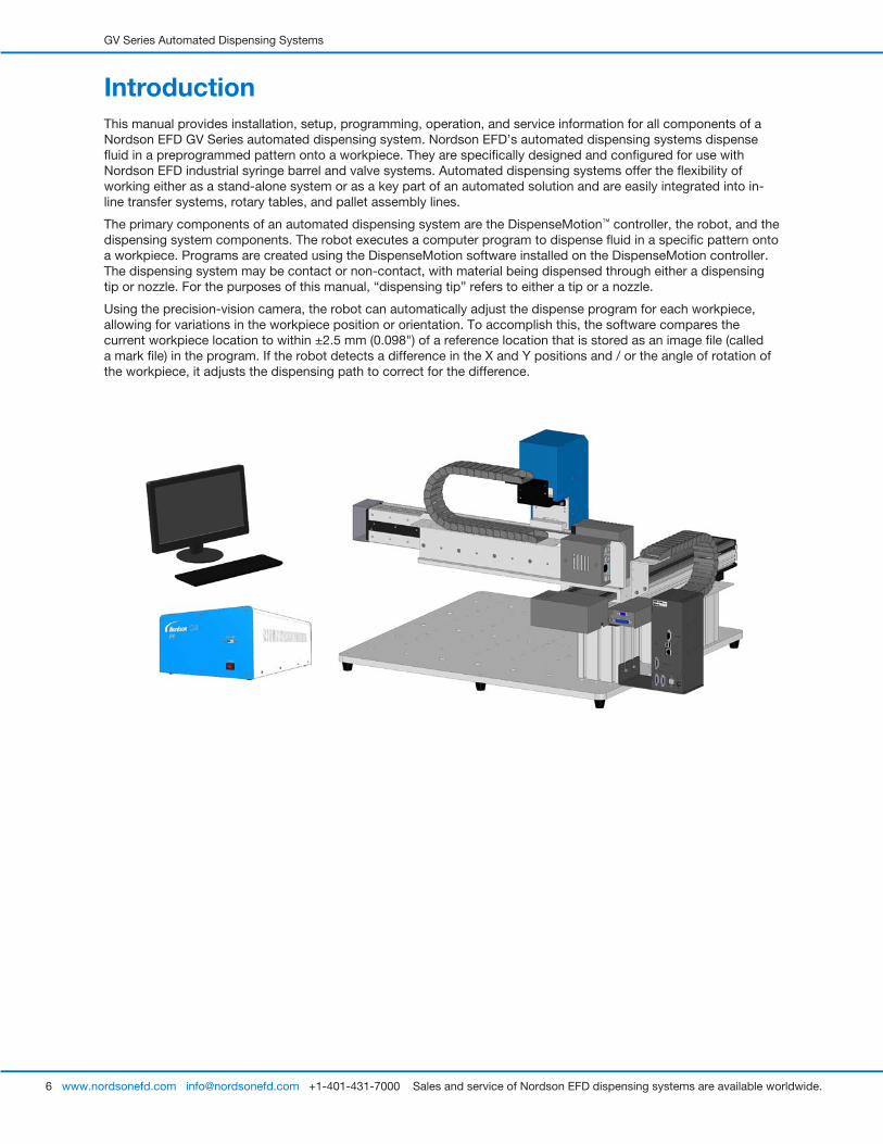
IntroductionThis manual provides installation, setup, programming, operation, and service information for all components of a Nordson EFD GV Series automated dispensing system. Nordson EFD’s automated dispensing systems dispense fluid in a preprogrammed pattern onto a workpiece. They are specifically designed and configured for use with Nordson EFD industrial syringe barrel and valve systems. Automated dispensing systems offer the flexibility of working either as a stand-alone system or as a key part of an automated solution and are easily integrated into in-line transfer systems, rotary tables, and pallet assembly lines.
The primary components of an automated dispensing system are the DispenseMotion™ controller, the robot, and the dispensing system components. The robot executes a computer program to dispense fluid in a specific pattern onto a workpiece. Programs are created using the DispenseMotion software installed on the DispenseMotion controller. The dispensing system may be contact or non-contact, with material being dispensed through either a dispensing tip or nozzle. For the purposes of this manual, “dispensing tip” refers to either a tip or a nozzle.
Using the precision-vision camera, the robot can automatically adjust the dispense program for each workpiece, allowing for variations in the workpiece position or orientation. To accomplish this, the software compares the current workpiece location to within ±2.5 mm (0.098") of a reference location that is stored as an image file (called a mark file) in the program. If the robot detects a difference in the X and Y positions and / or the angle of rotation of the workpiece, it adjusts the dispensing path to correct for the difference.
GV Series Automated Dispensing Systems
7www.nordsonefd.com [email protected] +1-401-431-7000 Sales and service of Nordson EFD dispensing systems are available worldwide.
Nordson EFD Product Safety Statement
The safety messages that follow have a CAUTION level hazard. Failure to comply may result in minor or moderate injury.
CAUTION
READ MANUAL
Read manual for proper use of this equipment. Follow all safety instructions. Task- and equipment-specific warnings, cautions, and instructions are included in equipment documentation where appropriate. Make sure these instructions and all other equipment documents are accessible to persons operating or servicing equipment.
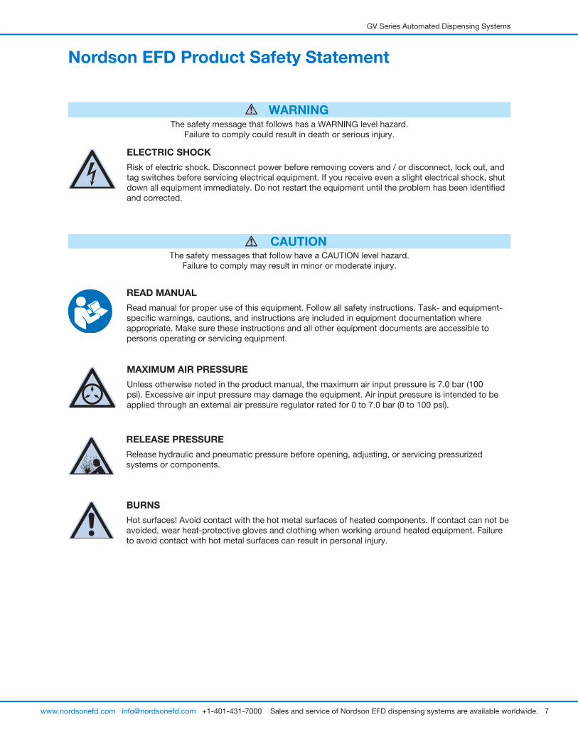
The safety message that follows has a WARNING level hazard. Failure to comply could result in death or serious injury.
WARNING
ELECTRIC SHOCK
Risk of electric shock. Disconnect power before removing covers and / or disconnect, lock out, and tag switches before servicing electrical equipment. If you receive even a slight electrical shock, shut down all equipment immediately. Do not restart the equipment until the problem has been identified and corrected.
MAXIMUM AIR PRESSURE
Unless otherwise noted in the product manual, the maximum air input pressure is 7.0 bar (100 psi). Excessive air input pressure may damage the equipment. Air input pressure is intended to be applied through an external air pressure regulator rated for 0 to 7.0 bar (0 to 100 psi).
RELEASE PRESSURE
Release hydraulic and pneumatic pressure before opening, adjusting, or servicing pressurized systems or components.
BURNS
Hot surfaces! Avoid contact with the hot metal surfaces of heated components. If contact can not be avoided, wear heat-protective gloves and clothing when working around heated equipment. Failure to avoid contact with hot metal surfaces can result in personal injury.
GV Series Automated Dispensing Systems
8 www.nordsonefd.com [email protected] +1-401-431-7000 Sales and service of Nordson EFD dispensing systems are available worldwide.
Nordson EFD Product Safety Statement (continued)
Halogenated Hydrocarbon Solvent HazardsDo not use halogenated hydrocarbon solvents in a pressurized system that contains aluminum components. Under pressure, these solvents can react with aluminum and explode, causing injury, death, or property damage. Halogenated hydrocarbon solvents contain one or more of the following elements.
Element Symbol Prefix Fluorine F “Fluoro-” Chlorine Cl “Chloro-” Bromine Br “Bromo-” Iodine I “Iodo-”
Check the Safety Data Sheet (SDS) or contact your material supplier for more information. If you must use halogenated hydrocarbon solvents, contact your EFD representative for compatible EFD components.
High Pressure FluidsHigh pressure fluids, unless they are safely contained, are extremely hazardous. Always release fluid pressure before adjusting or servicing high pressure equipment. A jet of high pressure fluid can cut like a knife and cause serious bodily injury, amputation, or death. Fluids penetrating the skin can also cause toxic poisoning.
WARNINGAny injury caused by high pressure liquid can be serious. If you are injured or even suspect an injury:
• Go to an emergency room immediately. • Tell the doctor that you suspect an injection injury.• Show the doctor the following note.• Tell the doctor what kind of material you were dispensing.
Medical Alert — Airless Spray Wounds: Note to Physician
Injection in the skin is a serious traumatic injury. It is important to treat the injury surgically as soon as possible. Do not delay treatment to research toxicity. Toxicity is a concern with some exotic coatings injected directly into the bloodstream.
Qualified PersonnelEquipment owners are responsible for making sure that EFD equipment is installed, operated, and serviced by qualified personnel. Qualified personnel are those employees or contractors who are trained to safely perform their assigned tasks. They are familiar with all relevant safety rules and regulations and are physically capable of performing their assigned tasks.
GV Series Automated Dispensing Systems
9www.nordsonefd.com [email protected] +1-401-431-7000 Sales and service of Nordson EFD dispensing systems are available worldwide.
Intended UseUse of EFD equipment in ways other than those described in the documentation supplied with the equipment may result in injury to persons or damage to property. Some examples of unintended use of equipment include:
• Using incompatible materials.• Making unauthorized modifications.• Removing or bypassing safety guards or interlocks.• Using incompatible or damaged parts.• Using unapproved auxiliary equipment.• Operating equipment in excess of maximum ratings.• Operating equipment in an explosive atmosphere.
Regulations and ApprovalsMake sure all equipment is rated and approved for the environment in which it is used. Any approvals obtained for Nordson EFD equipment will be voided if instructions for installation, operation, and service are not followed. If the equipment is used in a manner not specified by Nordson EFD, the protection provided by the equipment may be impaired.
Personal SafetyTo prevent injury, follow these instructions:
• Do not operate or service equipment unless you are qualified.
• Do not operate equipment unless safety guards, doors, and covers are intact and automatic interlocks are operating properly. Do not bypass or disarm any safety devices.
• Keep clear of moving equipment. Before adjusting or servicing moving equipment, shut off the power supply and wait until the equipment comes to a complete stop. Lock out power and secure the equipment to prevent unexpected movement.
• Make sure spray areas and other work areas are adequately ventilated.
• When using a syringe barrel, always keep the dispensing end of the tip pointing towards the work and away from the body or face. Store syringe barrels with the tip pointing down when they are not in use.
• Obtain and read the Safety Data Sheet (SDS) for all materials used. Follow the manufacturer’s instructions for safe handling and use of materials and use recommended personal protection devices.
• Be aware of less-obvious dangers in the workplace that often cannot be completely eliminated, such as hot surfaces, sharp edges, energized electrical circuits, and moving parts that cannot be enclosed or otherwise guarded for practical reasons.
• Know where emergency stop buttons, shutoff valves, and fire extinguishers are located.
• Wear hearing protection to protect against hearing loss that can be caused by exposure to vacuum exhaust port noise over long periods of time.
Nordson EFD Product Safety Statement (continued)
GV Series Automated Dispensing Systems
10 www.nordsonefd.com [email protected] +1-401-431-7000 Sales and service of Nordson EFD dispensing systems are available worldwide.
Nordson EFD Product Safety Statement (continued)
Fire SafetyTo prevent a fire or explosion, follow these instructions:
• Shut down all equipment immediately if you notice static sparking or arcing. Do not restart the equipment until the cause has been identified and corrected.
• Do not smoke, weld, grind, or use open flames where flammable materials are being used or stored.
• Do not heat materials to temperatures above those recommended by the manufacturer. Make sure heat monitoring and limiting devices are working properly.
• Provide adequate ventilation to prevent dangerous concentrations of volatile particles or vapors. Refer to local codes or the SDS for guidance.
• Do not disconnect live electrical circuits when working with flammable materials. Shut off power at a disconnect switch first to prevent sparking.
• Know where emergency stop buttons, shutoff valves, and fire extinguishers are located.
Preventive MaintenanceAs part of maintaining continuous trouble-free use of this product, Nordson EFD recommends the following simple preventive maintenance checks:
• Periodically inspect tube-to-fitting connections for proper fit. Secure as necessary.
• Check tubing for cracks and contamination. Replace tubing as necessary.
• Check all wiring connections for looseness. Tighten as necessary.
• Clean: If a front panel requires cleaning, use a clean, soft, damp rag with a mild detergent cleaner. DO NOT USE strong solvents (MEK, acetone, THF, etc.) as they will damage the front panel material.
• Maintain: Use only a clean, dry air supply to the unit. The equipment does not require any other regular maintenance.
• Test: Verify the operation of features and the performance of equipment using the appropriate sections of this manual. Return faulty or defective units to Nordson EFD for replacement.
• Use only replacement parts that are designed for use with the original equipment. Contact your Nordson EFD representative for information and advice.
GV Series Automated Dispensing Systems
11www.nordsonefd.com [email protected] +1-401-431-7000 Sales and service of Nordson EFD dispensing systems are available worldwide.
Important Disposable Component Safety InformationAll Nordson EFD disposable components, including syringe barrels, cartridges, pistons, tip caps, end caps, and dispense tips, are precision engineered for one-time use. Attempting to clean and re-use components will compromise dispensing accuracy and may increase the risk of personal injury.
Always wear appropriate protective equipment and clothing suitable for your dispensing application and adhere to the following guidelines:
• Do not heat syringe barrels or cartridges to a temperature greater than 38° C (100° F).• Dispose of components according to local regulations after one-time use.• Do not clean components with strong solvents (MEK, acetone, THF, etc.).• Clean cartridge retainer systems and barrel loaders with mild detergents only.• To prevent fluid waste, use Nordson EFD SmoothFlow™ pistons.
Action in the Event of a MalfunctionIf a system or any equipment in a system malfunctions, shut off the system immediately and perform the following steps:
1. Disconnect and lock out system electrical power. If using hydraulic and pneumatic shutoff valves, close and relieve pressure.
2. For Nordson EFD air-powered dispensers, remove the syringe barrel from the adapter assembly. For Nordson EFD electro-mechanical dispensers, slowly unscrew the barrel retainer and remove the barrel from the actuator.
3. Identify the reason for the malfunction and correct it before restarting the system.
DisposalDispose of equipment and materials used in operation and servicing according to local codes.
Nordson EFD Product Safety Statement (continued)
GV Series Automated Dispensing Systems
12 www.nordsonefd.com [email protected] +1-401-431-7000 Sales and service of Nordson EFD dispensing systems are available worldwide.
Equipment-Specific Safety InformationThe following safety information is specific to Nordson EFD automated dispensing systems.
European Community
To meet the requirements of the European Community (CE) safety directives, the robot must be placed in an enclosure. The enclosure prevents an operator from entering the robot’s work area and generates an emergency stop signal if the door switch is opened while the robot is running.
WARNINGInstall the 8-pin input / output safety plug only to bypass the start / stop box. When this plug is installed, the installer assumes all safety liability.
Installation Location
Do not store, install, or operate the robot in a location where it is exposed to the following:
• Temperatures lower or higher than 0–40° C (50–104° F) or humidity lower or higher than 20–95%
• Direct sunlight
• Electrical noise
• Flammable or corrosive gases
• Dust or iron powder
• Sources of splashing water, oil, or chemicals
• Radioactive materials, magnetic fields, or vacuum rooms
Power and Grounding
• Connect the robot and accessories to a properly grounded power source.
• Make sure the system is connected to the correct voltage.
Operation and Service
• Turn on the dust collection system before operating the robot.
• Do not drop or spill foreign objects or material, such as screws or liquids, into the robot.
• Do not overload the robot.
• Do not touch any part of the robot while it is running. Load and unload workpieces or material only when the robot is stopped.
• Disconnect and lock out power to the system before changing fixtures or tooling.
• Use only a neutral detergent for cleaning. Do not use alcohol, benzene, or thinner.
Nordson EFD Product Safety Statement (continued)
GV Series Automated Dispensing Systems
13www.nordsonefd.com [email protected] +1-401-431-7000 Sales and service of Nordson EFD dispensing systems are available worldwide.
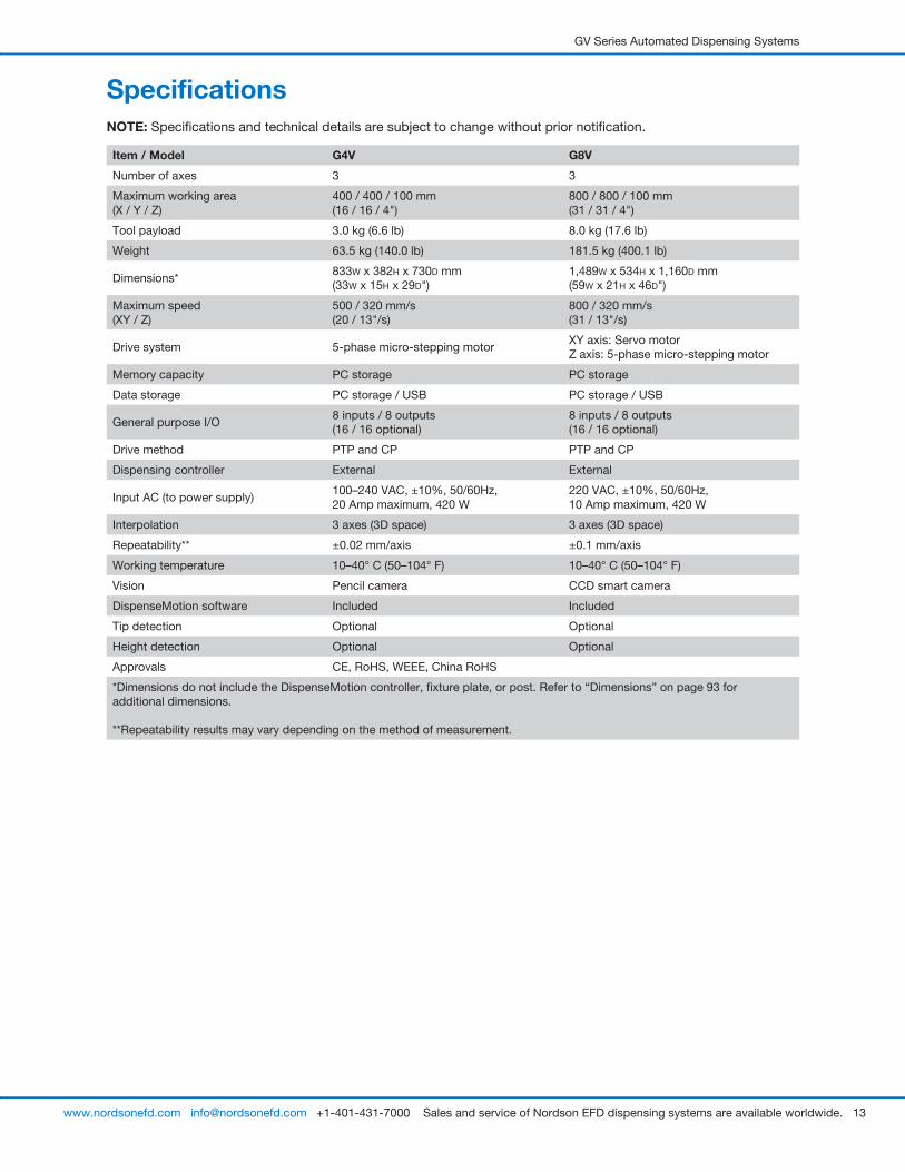
SpecificationsNOTE: Specifications and technical details are subject to change without prior notification.
Item / Model G4V G8V
Number of axes 3 3
Maximum working area (X / Y / Z)
400 / 400 / 100 mm (16 / 16 / 4")
800 / 800 / 100 mm (31 / 31 / 4")
Tool payload 3.0 kg (6.6 lb) 8.0 kg (17.6 lb)
Weight 63.5 kg (140.0 lb) 181.5 kg (400.1 lb)
Dimensions*833W x 382H x 730D mm (33W x 15H x 29D")
1,489W x 534H x 1,160D mm (59W x 21H x 46D")
Maximum speed (XY / Z)
500 / 320 mm/s (20 / 13"/s)
800 / 320 mm/s (31 / 13"/s)
Drive system 5-phase micro-stepping motorXY axis: Servo motorZ axis: 5-phase micro-stepping motor
Memory capacity PC storage PC storage
Data storage PC storage / USB PC storage / USB
General purpose I/O8 inputs / 8 outputs (16 / 16 optional)
8 inputs / 8 outputs (16 / 16 optional)
Drive method PTP and CP PTP and CP
Dispensing controller External External
Input AC (to power supply)100–240 VAC, ±10%, 50/60Hz,20 Amp maximum, 420 W
220 VAC, ±10%, 50/60Hz,10 Amp maximum, 420 W
Interpolation 3 axes (3D space) 3 axes (3D space)
Repeatability** ±0.02 mm/axis ±0.1 mm/axis
Working temperature 10–40° C (50–104° F) 10–40° C (50–104° F)
Vision Pencil camera CCD smart camera
DispenseMotion software Included Included
Tip detection Optional Optional
Height detection Optional Optional
Approvals CE, RoHS, WEEE, China RoHS
*Dimensions do not include the DispenseMotion controller, fixture plate, or post. Refer to “Dimensions” on page 93 for additional dimensions.
**Repeatability results may vary depending on the method of measurement.
GV Series Automated Dispensing Systems
14 www.nordsonefd.com [email protected] +1-401-431-7000 Sales and service of Nordson EFD dispensing systems are available worldwide.
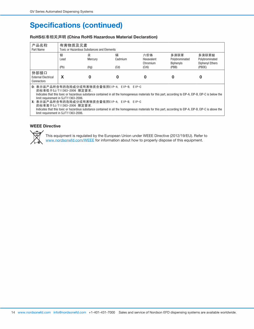
Specifications (continued)RoHS标准相关声明标准相关声明 (China RoHS Hazardous Material Declaration)
产品名称Part Name
有害物质及元素Toxic or Hazardous Substances and Elements
铅Lead
(Pb)
汞Mercury
(Hg)
镉Cadmium
(Cd)
六价铬Hexavalent Chromium(Cr6)
多溴联苯Polybrominated Biphenyls(PBB)
多溴联苯醚Polybrominated Diphenyl Ethers(PBDE)
外部接口External Electrical Connectors
X 0 0 0 0 0
O: 表示该产品所含有的危险成分或有害物质含量依照EIP-A, EIP-B, EIP-C 的标准低于SJ/T11363-2006 限定要求。 Indicates that this toxic or hazardous substance contained in all the homogeneous materials for this part, according to EIP-A, EIP-B, EIP-C is below the limit requirement in SJ/T11363-2006.
X: 表示该产品所含有的危险成分或有害物质含量依照EIP-A, EIP-B, EIP-C 的标准高于SJ/T11363-2006 限定要求. Indicates that this toxic or hazardous substance contained in all the homogeneous materials for this part, according to EIP-A, EIP-B, EIP-C is above the limit requirement in SJ/T11363-2006.
WEEE Directive
This equipment is regulated by the European Union under WEEE Directive (2012/19/EU). Refer to www.nordsonefd.com/WEEE for information about how to properly dispose of this equipment.
GV Series Automated Dispensing Systems
15www.nordsonefd.com [email protected] +1-401-431-7000 Sales and service of Nordson EFD dispensing systems are available worldwide.
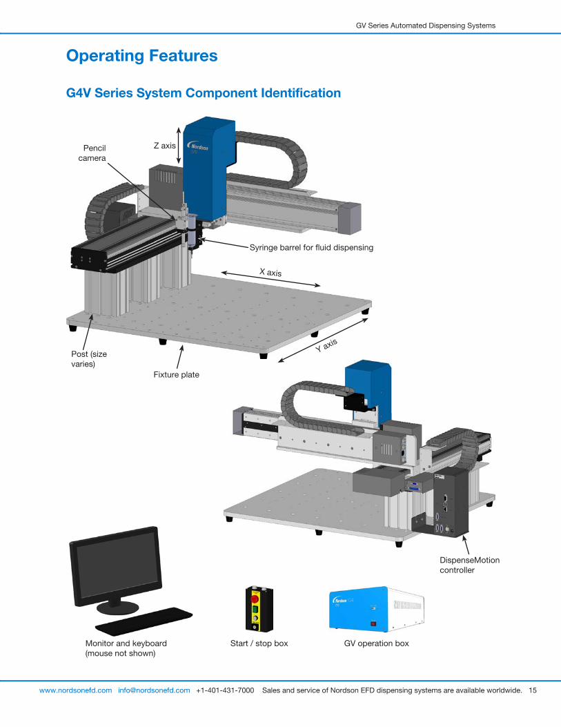
Pencil camera
DispenseMotion controller
Syringe barrel for fluid dispensing
Operating Features
G4V Series System Component Identification
Post (size varies)
Fixture plate
Monitor and keyboard (mouse not shown)
GV operation boxStart / stop box
X axis
Z axis
Y axis
GV Series Automated Dispensing Systems
16 www.nordsonefd.com [email protected] +1-401-431-7000 Sales and service of Nordson EFD dispensing systems are available worldwide.
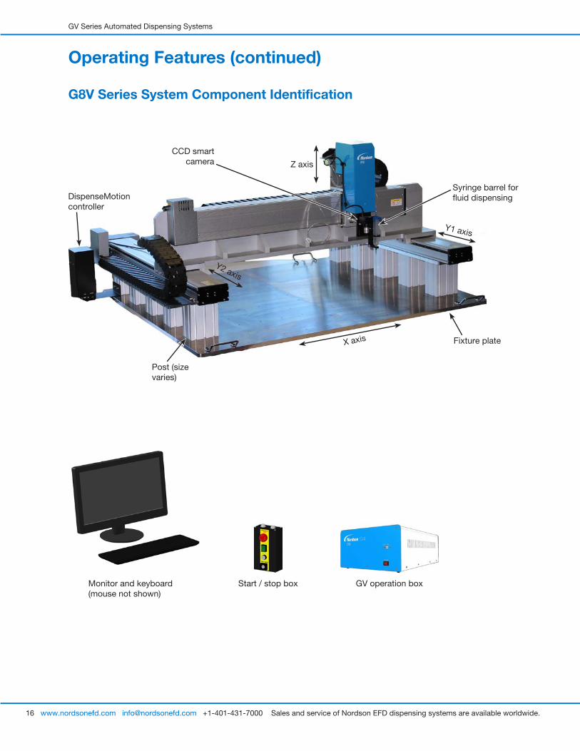
G8V Series System Component Identification
Operating Features (continued)
CCD smart camera
Syringe barrel for fluid dispensing
Post (size varies)
Fixture plate
DispenseMotion controller
Monitor and keyboard (mouse not shown)
GV operation boxStart / stop box
X axis
Y1 axis
Y2 axis
Z axis
GV Series Automated Dispensing Systems
17www.nordsonefd.com [email protected] +1-401-431-7000 Sales and service of Nordson EFD dispensing systems are available worldwide.
Operating Features (continued)
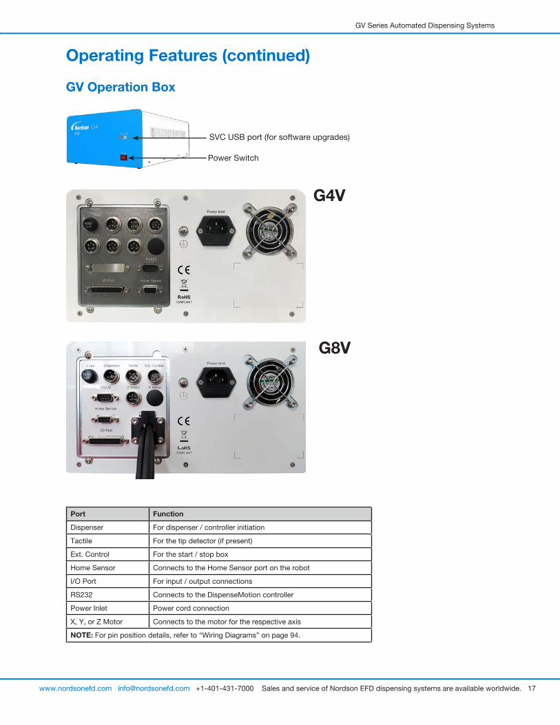
GV Operation Box
SVC USB port (for software upgrades)
Power Switch
Port Function
Dispenser For dispenser / controller initiation
Tactile For the tip detector (if present)
Ext. Control For the start / stop box
Home Sensor Connects to the Home Sensor port on the robot
I/O Port For input / output connections
RS232 Connects to the DispenseMotion controller
Power Inlet Power cord connection
X, Y, or Z Motor Connects to the motor for the respective axis
NOTE: For pin position details, refer to “Wiring Diagrams” on page 94.
G4V
G8V

GV Series Automated Dispensing Systems
18 www.nordsonefd.com [email protected] +1-401-431-7000 Sales and service of Nordson EFD dispensing systems are available worldwide.
CameraThe system includes a precision-vision camera that allows you to view the fixture plate and to focus.
CCD Smart Camera Features How to Focus
Converts the analog camera image pixels to digital values for extremely precise image management
• Move the camera up or down to focus the image.
• If the optional light accessory is present, use the light controller dial to adjust the exposure (how much light is allowed into the image).
Fixed focal length (must move the camera up and down to focus it)
Variety of lenses available (for different focal lengths, fields of view, etc.). Refer to “Accessories” on page 89 for the optional lens kit part number.
Pencil Camera Features How to Focus
Locking bracket for focus dial
Location of screw used to adjust light intensity
White diffuser cap
Combination of manual focus and on / off dial
To focus the image:
• Without moving the robot, loosen the screws that secure the focus dial bracket.
• Turn the focus dial on the camera until the sharpest image is obtained.
• Tighten the focus dial bracket screws.
To adjust the exposure:
• Use a small Phillips screwdriver to adjust the camera light such that the light setting will make the workpiece surface visible regardless of any changes in the ambient light.
NOTE: The screw is located inside the camera housing.
Integrated lighting with an adjustable light-intensity dial
NOTE: To turn the light off, use a small flat-blade screwdriver to turn the screw inside the camera bracket fully counterclockwise.
White diffuser cap for image enhancement (can be removed)
Start / Stop Box
Operating Features (continued)
For the shorted plug Connects to Ext.
Control on the GV operation box
EMERGENCY STOP button
START button
RESET button
RUN / TEACH key
GV Series Automated Dispensing Systems
19www.nordsonefd.com [email protected] +1-401-431-7000 Sales and service of Nordson EFD dispensing systems are available worldwide.
InstallationUse this section in tandem with the Quick Start Guide and the valve system manuals to install all components of the system.
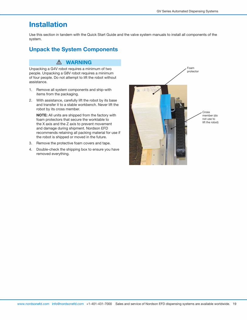
Unpack the System Components
WARNINGUnpacking a G4V robot requires a minimum of two people. Unpacking a G8V robot requires a minimum of four people. Do not attempt to lift the robot without assistance.
1. Remove all system components and ship-with items from the packaging.
2. With assistance, carefully lift the robot by its base and transfer it to a stable workbench. Never lift the robot by its cross member.
NOTE: All units are shipped from the factory with foam protectors that secure the worktable to the X axis and the Z axis to prevent movement and damage during shipment. Nordson EFD recommends retaining all packing material for use if the robot is shipped or moved in the future.
3. Remove the protective foam covers and tape.
4. Double-check the shipping box to ensure you have removed everything.
Foam protector
Cross member (do not use to lift the robot)
GV Series Automated Dispensing Systems
20 www.nordsonefd.com [email protected] +1-401-431-7000 Sales and service of Nordson EFD dispensing systems are available worldwide.
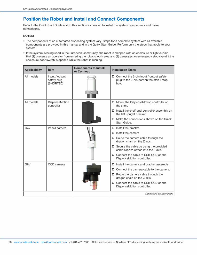
Position the Robot and Install and Connect ComponentsRefer to the Quick Start Guide and to this section as needed to install the system components and make connections.
NOTES:
• The components of an automated dispensing system vary. Steps for a complete system with all available components are provided in this manual and in the Quick Start Guide. Perform only the steps that apply to your system.
• If the system is being used in the European Community, the robot is shipped with an enclosure or light curtain that (1) prevents an operator from entering the robot’s work area and (2) generates an emergency stop signal if the enclosure door switch is opened while the robot is running.
Applicability Item Components to Install or Connect Installation Tasks
All models Input / output safety plug (SHORTED)
� Connect the 2-pin input / output safety plug to the 2-pin port on the start / stop box.
All models DispenseMotion controller
� Mount the DispenseMotion controller on the shelf.
� Install the shelf-and-controller assembly on the left upright bracket.
� Make the connections shown on the Quick Start Guide.
G4V Pencil camera � Install the bracket.
� Install the camera.
� Route the camera cable through the dragon chain on the Z axis.
� Secure the cable by using the provided cable clips to attach it to the Z axis.
� Connect the cable to USB-CCD on the DispenseMotion controller.
G8V CCD camera � Install the camera and bracket assembly.
� Connect the camera cable to the camera.
� Route the camera cable through the dragon chain on the Z axis.
� Connect the cable to USB-CCD on the DispenseMotion controller.
Continued on next page
GV Series Automated Dispensing Systems
21www.nordsonefd.com [email protected] +1-401-431-7000 Sales and service of Nordson EFD dispensing systems are available worldwide.
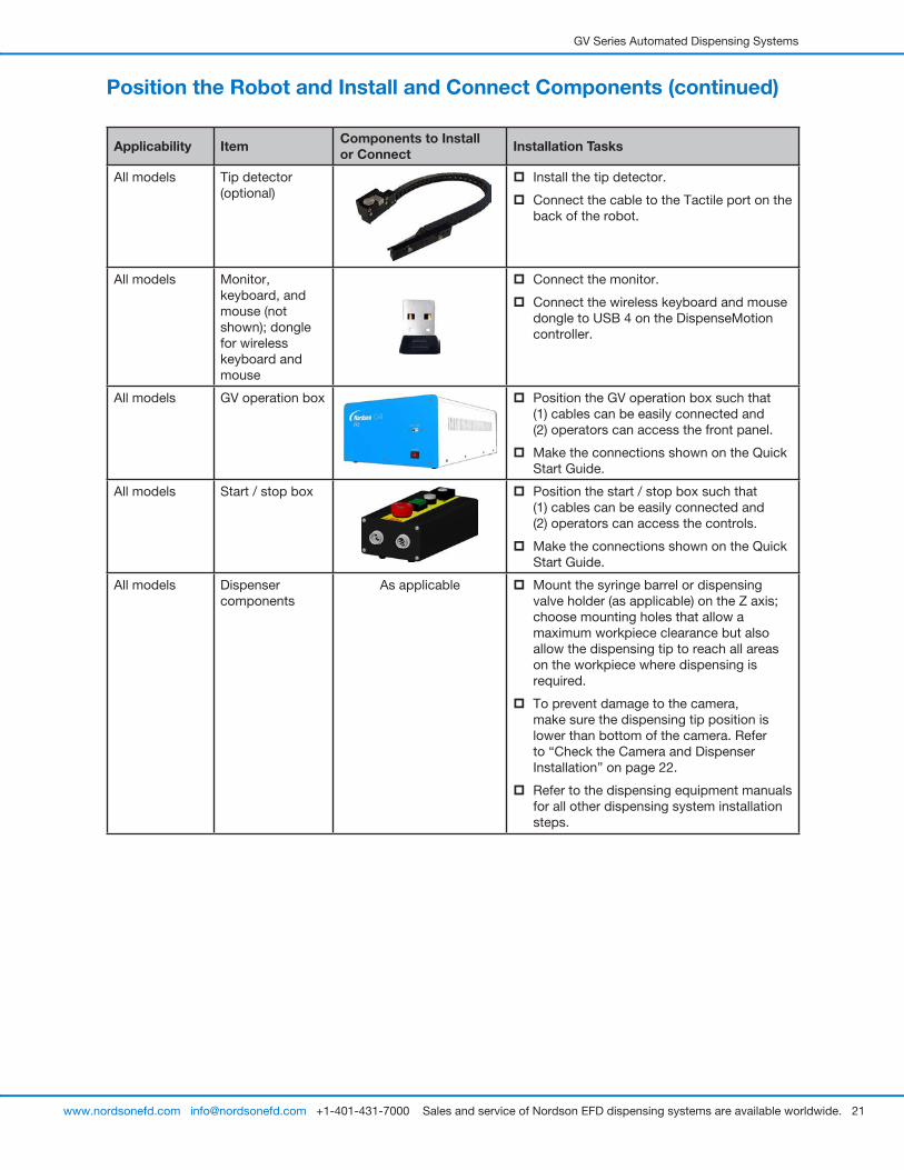
Position the Robot and Install and Connect Components (continued)
Applicability Item Components to Install or Connect Installation Tasks
All models Tip detector (optional)
� Install the tip detector.
� Connect the cable to the Tactile port on the back of the robot.
All models Monitor, keyboard, and mouse (not shown); dongle for wireless keyboard and mouse
� Connect the monitor.
� Connect the wireless keyboard and mouse dongle to USB 4 on the DispenseMotion controller.
All models GV operation box � Position the GV operation box such that (1) cables can be easily connected and (2) operators can access the front panel.
� Make the connections shown on the Quick Start Guide.
All models Start / stop box � Position the start / stop box such that (1) cables can be easily connected and (2) operators can access the controls.
� Make the connections shown on the Quick Start Guide.
All models Dispenser components
As applicable � Mount the syringe barrel or dispensing valve holder (as applicable) on the Z axis; choose mounting holes that allow a maximum workpiece clearance but also allow the dispensing tip to reach all areas on the workpiece where dispensing is required.
� To prevent damage to the camera, make sure the dispensing tip position is lower than bottom of the camera. Refer to “Check the Camera and Dispenser Installation” on page 22.
� Refer to the dispensing equipment manuals for all other dispensing system installation steps.
GV Series Automated Dispensing Systems
22 www.nordsonefd.com [email protected] +1-401-431-7000 Sales and service of Nordson EFD dispensing systems are available worldwide.
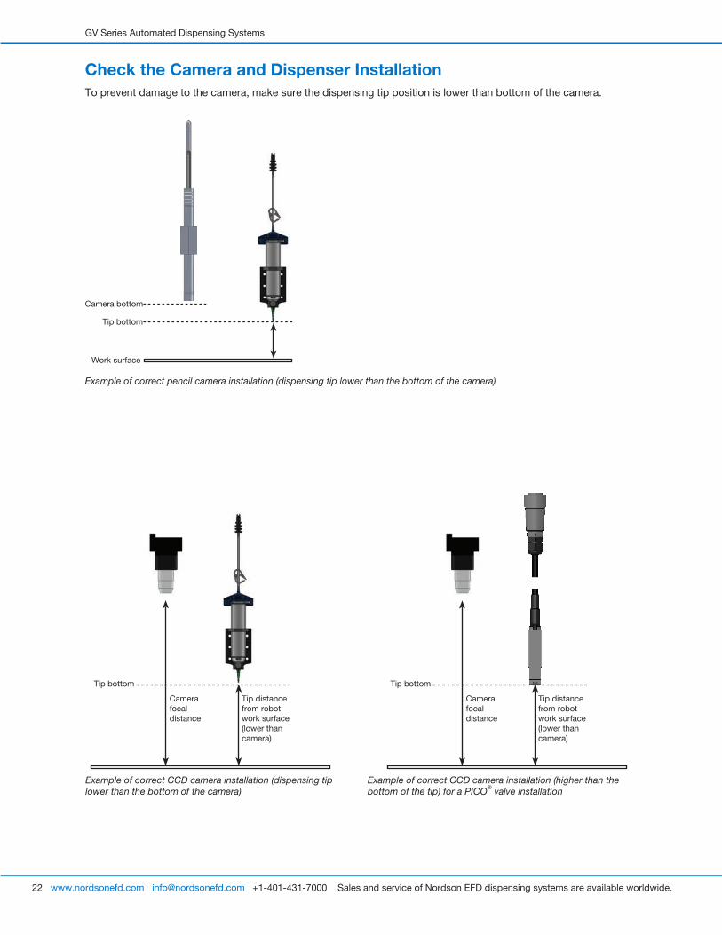
Check the Camera and Dispenser InstallationTo prevent damage to the camera, make sure the dispensing tip position is lower than bottom of the camera.
Example of correct pencil camera installation (dispensing tip lower than the bottom of the camera)
Tip bottom
Camera bottom
Work surface
Example of correct CCD camera installation (dispensing tip lower than the bottom of the camera)
Example of correct CCD camera installation (higher than the bottom of the tip) for a PICO® valve installation
Camera focal distance
Tip distance from robot work surface (lower than camera)
Tip bottom
Camera focal distance
Tip distance from robot work surface (lower than camera)
Tip bottom
GV Series Automated Dispensing Systems
23www.nordsonefd.com [email protected] +1-401-431-7000 Sales and service of Nordson EFD dispensing systems are available worldwide.
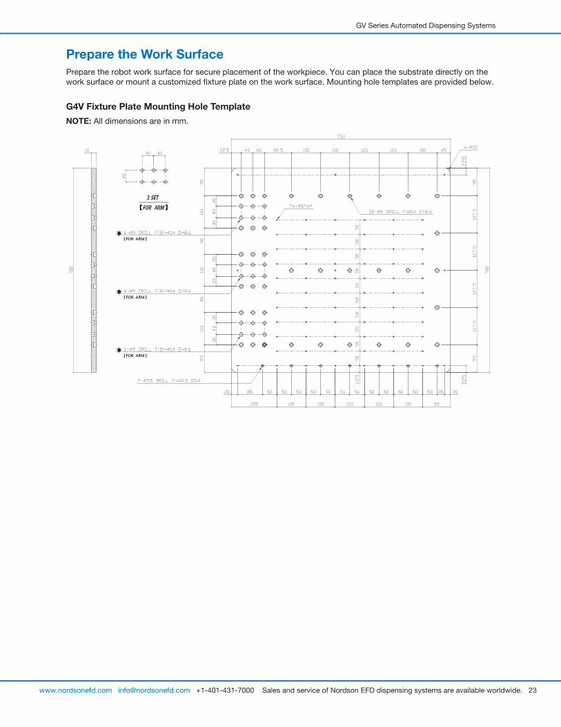
Prepare the Work SurfacePrepare the robot work surface for secure placement of the workpiece. You can place the substrate directly on the work surface or mount a customized fixture plate on the work surface. Mounting hole templates are provided below.
G4V Fixture Plate Mounting Hole Template
NOTE: All dimensions are in mm.

GV Series Automated Dispensing Systems
24 www.nordsonefd.com [email protected] +1-401-431-7000 Sales and service of Nordson EFD dispensing systems are available worldwide.
Connect Inputs / Outputs (Optional)All automated dispensing systems provide 8 standard inputs and 8 standard outputs. Connect input / output wiring to the I/O PORT connection on the back of the GV operation box. For a wiring diagram, refer to “I/O Port” on page 95. There are several ways to use the system inputs / outputs. Refer to “Setting Up Inputs / Outputs” on page 58 for additional information on inputs / outputs.
G8V Fixture Plate Mounting Hole Template
NOTE: All dimensions are in mm.
Prepare the Work Surface (continued)
GV Series Automated Dispensing Systems
25www.nordsonefd.com [email protected] +1-401-431-7000 Sales and service of Nordson EFD dispensing systems are available worldwide.
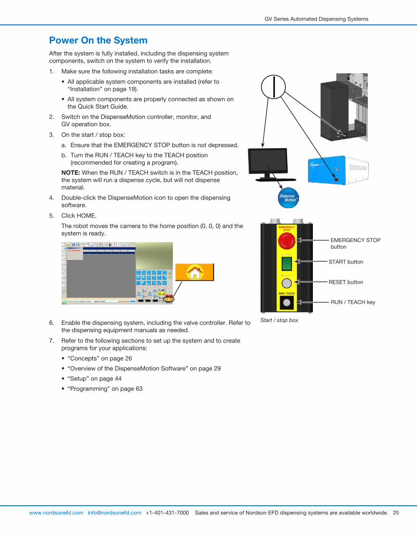
Power On the SystemAfter the system is fully installed, including the dispensing system components, switch on the system to verify the installation.
1. Make sure the following installation tasks are complete:
• All applicable system components are installed (refer to “Installation” on page 19).
• All system components are properly connected as shown on the Quick Start Guide.
2. Switch on the DispenseMotion controller, monitor, and GV operation box.
3. On the start / stop box:
a. Ensure that the EMERGENCY STOP button is not depressed.
b. Turn the RUN / TEACH key to the TEACH position (recommended for creating a program).
NOTE: When the RUN / TEACH switch is in the TEACH position, the system will run a dispense cycle, but will not dispense material.
4. Double-click the DispenseMotion icon to open the dispensing software.
5. Click HOME.
The robot moves the camera to the home position (0, 0, 0) and the system is ready.
6. Enable the dispensing system, including the valve controller. Refer to the dispensing equipment manuals as needed.
7. Refer to the following sections to set up the system and to create programs for your applications:
• “Concepts” on page 26
• “Overview of the DispenseMotion Software” on page 29
• “Setup” on page 44
• “Programming” on page 63
Start / stop box
EMERGENCY STOP button
START button
RESET button
RUN / TEACH key
GV Series Automated Dispensing Systems
26 www.nordsonefd.com [email protected] +1-401-431-7000 Sales and service of Nordson EFD dispensing systems are available worldwide.
ConceptsBefore creating any programs, make sure you understand the concepts explained in this section.
About Programs and CommandsA program is a set of commands stored as a file. Each command is stored in the file as a numbered address. Commands can be subdivided into the following command types:
• A setup command sets a program-level parameter, such as an XYZ coordinate or the Z clearance height.
• A dispense command is tied to an XYZ coordinate and automatically sends a signal to the dispensing system to execute the dispense command.
When the robot executes a program, it steps through each address in sequence and executes the command contained in that address. If an address contains a setup command, the system registers that command. If an address contains a dispense command, the robot moves the X, Y, and Z axes to the location specified for that command and then performs the dispense command.
Dispense commands are the building blocks of patterns. To program a dispense command, the dispensing tip is jogged to the desired XYZ location and then a dispense command is registered for that location. This action is repeated until the desired dispensing pattern is complete. Several examples are provided below.
Setup commands dictate how dispense commands will be executed. Nordson EFD recommends inserting setup commands at the beginning of a program. The following setup commands are the most commonly used: Backtrack Setup, Dispense Dot Setup, Dispense End Setup, Line Dispense Setup, Line Speed, and Z Clearance Setup.
Dispense Command Examples
Commands Resulting Pattern (Overhead View)
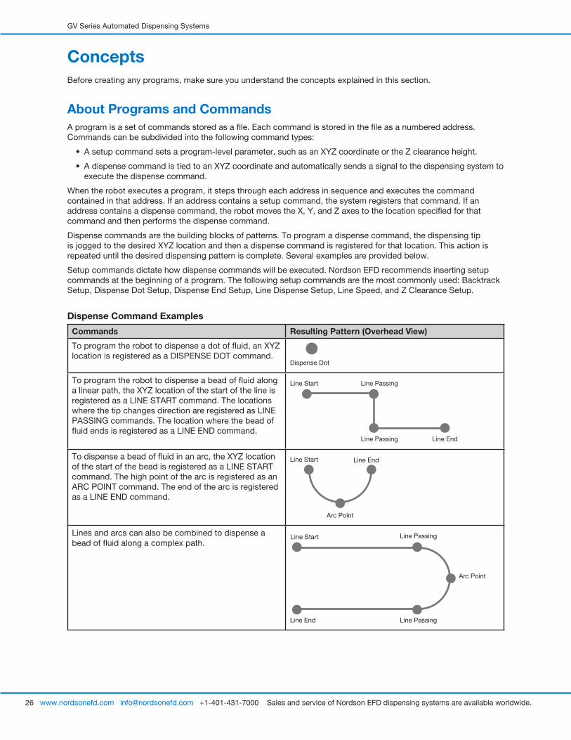
To program the robot to dispense a dot of fluid, an XYZ location is registered as a DISPENSE DOT command.
Dispense Dot
To program the robot to dispense a bead of fluid along a linear path, the XYZ location of the start of the line is registered as a LINE START command. The locations where the tip changes direction are registered as LINE PASSING commands. The location where the bead of fluid ends is registered as a LINE END command.
Line Start
Line EndLine Passing
Line Passing
To dispense a bead of fluid in an arc, the XYZ location of the start of the bead is registered as a LINE START command. The high point of the arc is registered as an ARC POINT command. The end of the arc is registered as a LINE END command.
Arc Point
Line Start Line End
Lines and arcs can also be combined to dispense a bead of fluid along a complex path.
Line Start
Line End
Arc Point
Line Passing
Line Passing
GV Series Automated Dispensing Systems
27www.nordsonefd.com [email protected] +1-401-431-7000 Sales and service of Nordson EFD dispensing systems are available worldwide.
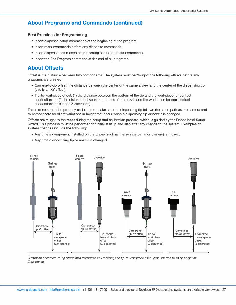
About OffsetsOffset is the distance between two components. The system must be “taught” the following offsets before any programs are created:
• Camera-to-tip offset: the distance between the center of the camera view and the center of the dispensing tip (this is an XY offset).
• Tip-to-workpiece offset: (1) the distance between the bottom of the tip and the workpiece for contact applications or (2) the distance between the bottom of the nozzle and the workpiece for non-contact applications (this is the Z clearance).
These offsets must be properly calibrated to make sure the dispensing tip follows the same path as the camera and to compensate for slight variations in height that occur when a dispensing tip or nozzle is changed.
Offsets are taught to the robot during the setup and calibration process, which is guided by the Robot Initial Setup wizard. This process must be performed for initial startup and also after any change to the system. Examples of system changes include the following:
• Any time a component installed on the Z axis (such as the syringe barrel or camera) is moved.
• Any time a dispensing tip or nozzle is changed.
About Programs and Commands (continued)
Best Practices for Programming
• Insert dispense setup commands at the beginning of the program.
• Insert mark commands before any dispense commands.
• Insert dispense commands after inserting setup and mark commands.
• Insert the End Program command at the end of all programs.
Illustration of camera-to-tip offset (also referred to as XY offset) and tip-to-workpiece offset (also referred to as tip height or Z clearance)
Camera-to-tip XY offset
Tip-to-workpiece offset (Z clearance)
Tip (nozzle)-to-workpiece offset (Z clearance)
Tip-to-workpiece offset (Z clearance)
Tip (nozzle)-to-workpiece offset (Z clearance)
Camera-to-tip XY offset
Camera-to-tip XY offset
Camera-to-tip XY offset
Pencil camera
CCD camera
Syringe barrel
Jet valve
CCD camera
Pencil camera
Syringe barrel
Jet valve
GV Series Automated Dispensing Systems
28 www.nordsonefd.com [email protected] +1-401-431-7000 Sales and service of Nordson EFD dispensing systems are available worldwide.
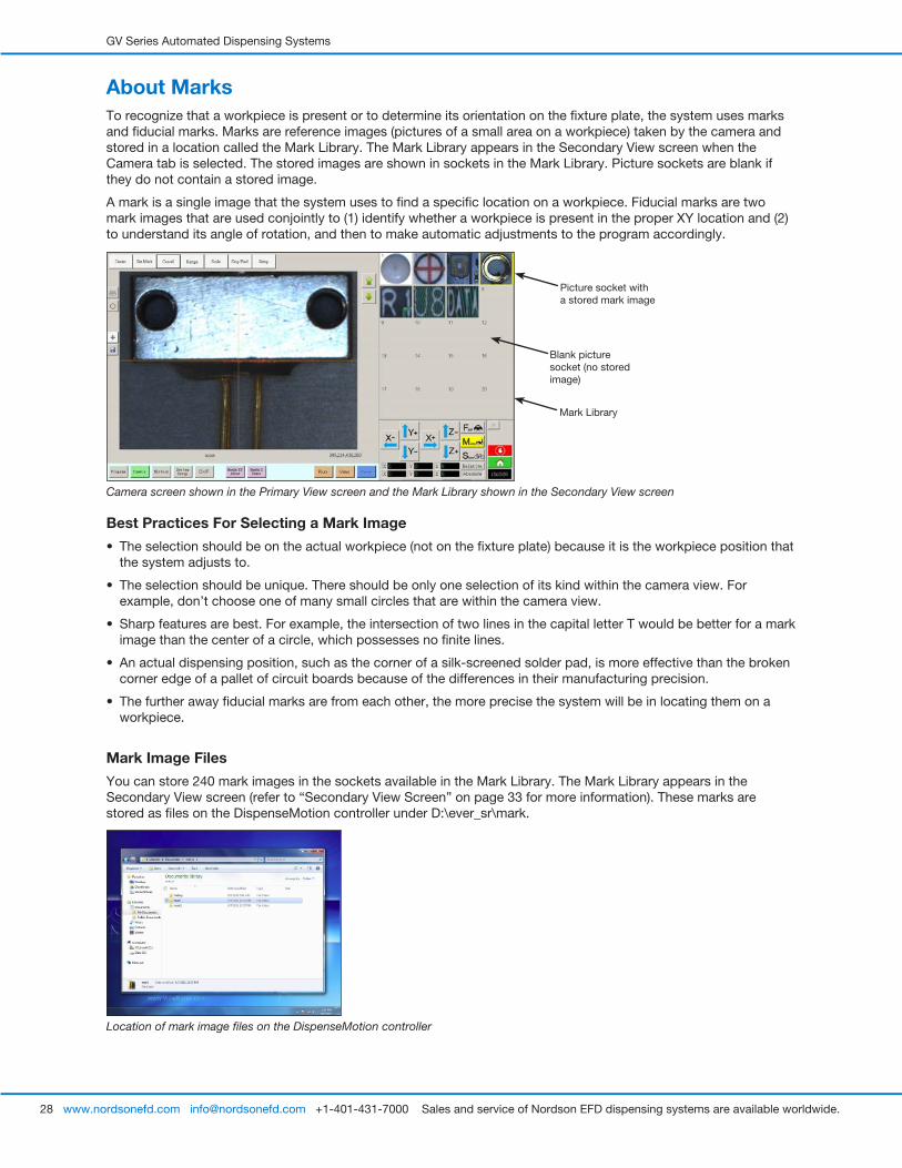
About MarksTo recognize that a workpiece is present or to determine its orientation on the fixture plate, the system uses marks and fiducial marks. Marks are reference images (pictures of a small area on a workpiece) taken by the camera and stored in a location called the Mark Library. The Mark Library appears in the Secondary View screen when the Camera tab is selected. The stored images are shown in sockets in the Mark Library. Picture sockets are blank if they do not contain a stored image.
A mark is a single image that the system uses to find a specific location on a workpiece. Fiducial marks are two mark images that are used conjointly to (1) identify whether a workpiece is present in the proper XY location and (2) to understand its angle of rotation, and then to make automatic adjustments to the program accordingly.
Picture socket with a stored mark image
Blank picture socket (no stored image)
Location of mark image files on the DispenseMotion controller
Best Practices For Selecting a Mark Image
• The selection should be on the actual workpiece (not on the fixture plate) because it is the workpiece position that the system adjusts to.
• The selection should be unique. There should be only one selection of its kind within the camera view. For example, don’t choose one of many small circles that are within the camera view.
• Sharp features are best. For example, the intersection of two lines in the capital letter T would be better for a mark image than the center of a circle, which possesses no finite lines.
• An actual dispensing position, such as the corner of a silk-screened solder pad, is more effective than the broken corner edge of a pallet of circuit boards because of the differences in their manufacturing precision.
• The further away fiducial marks are from each other, the more precise the system will be in locating them on a workpiece.
Mark Image Files
You can store 240 mark images in the sockets available in the Mark Library. The Mark Library appears in the Secondary View screen (refer to “Secondary View Screen” on page 33 for more information). These marks are stored as files on the DispenseMotion controller under D:\ever_sr\mark.
Camera screen shown in the Primary View screen and the Mark Library shown in the Secondary View screen
Mark Library
GV Series Automated Dispensing Systems
29www.nordsonefd.com [email protected] +1-401-431-7000 Sales and service of Nordson EFD dispensing systems are available worldwide.
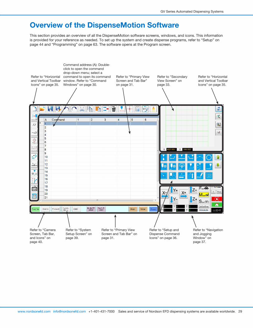
Refer to “Navigation and Jogging Window” on page 37.
Refer to “Horizontal and Vertical Toolbar Icons” on page 35.
Refer to “Setup and Dispense Command Icons” on page 36.
Refer to “Secondary View Screen” on page 33.
Overview of the DispenseMotion SoftwareThis section provides an overview of all the DispenseMotion software screens, windows, and icons. This information is provided for your reference as needed. To set up the system and create dispense programs, refer to “Setup” on page 44 and “Programming” on page 63. The software opens at the Program screen.
Refer to “System Setup Screen” on page 39.
Refer to “Camera Screen, Tab Bar, and Icons” on page 40.
Refer to “Primary View Screen and Tab Bar” on page 31.
Refer to “Primary View Screen and Tab Bar” on page 31.
Refer to “Horizontal and Vertical Toolbar Icons” on page 35.
Command address (A): Double-click to open the command drop-down menu; select a command to open its command window. Refer to “Command Windows” on page 30.
GV Series Automated Dispensing Systems
30 www.nordsonefd.com [email protected] +1-401-431-7000 Sales and service of Nordson EFD dispensing systems are available worldwide.
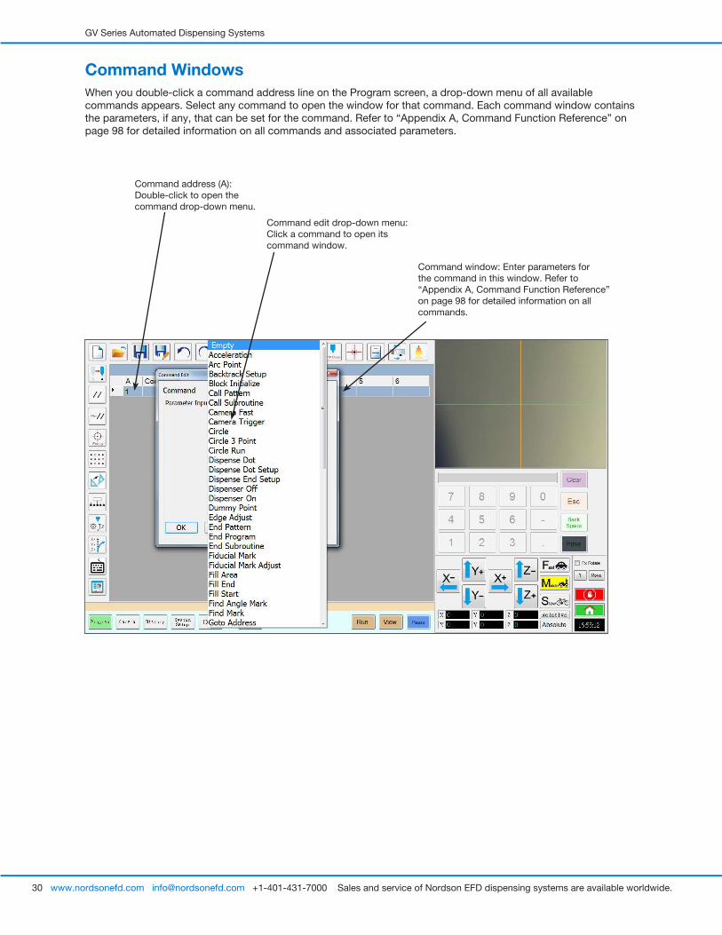
Command WindowsWhen you double-click a command address line on the Program screen, a drop-down menu of all available commands appears. Select any command to open the window for that command. Each command window contains the parameters, if any, that can be set for the command. Refer to “Appendix A, Command Function Reference” on page 98 for detailed information on all commands and associated parameters.
Command window: Enter parameters for the command in this window. Refer to “Appendix A, Command Function Reference” on page 98 for detailed information on all commands.
Command address (A): Double-click to open the command drop-down menu.
Command edit drop-down menu: Click a command to open its command window.
GV Series Automated Dispensing Systems
31www.nordsonefd.com [email protected] +1-401-431-7000 Sales and service of Nordson EFD dispensing systems are available worldwide.
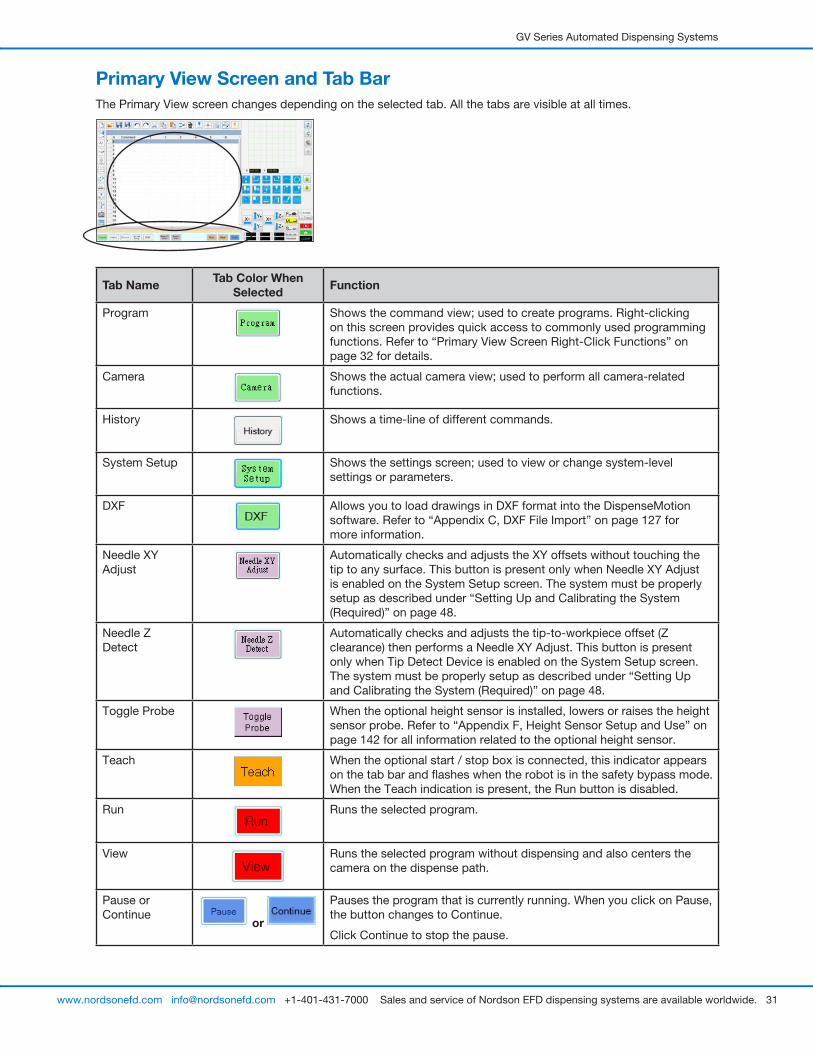
Primary View Screen and Tab BarThe Primary View screen changes depending on the selected tab. All the tabs are visible at all times.
Tab Name Tab Color When Selected Function
Program Shows the command view; used to create programs. Right-clicking on this screen provides quick access to commonly used programming functions. Refer to “Primary View Screen Right-Click Functions” on page 32 for details.
Camera Shows the actual camera view; used to perform all camera-related functions.
History Shows a time-line of different commands.
System Setup Shows the settings screen; used to view or change system-level settings or parameters.
DXF Allows you to load drawings in DXF format into the DispenseMotion software. Refer to “Appendix C, DXF File Import” on page 127 for more information.
Needle XY Adjust
Automatically checks and adjusts the XY offsets without touching the tip to any surface. This button is present only when Needle XY Adjust is enabled on the System Setup screen. The system must be properly setup as described under “Setting Up and Calibrating the System (Required)” on page 48.
Needle Z Detect
Automatically checks and adjusts the tip-to-workpiece offset (Z clearance) then performs a Needle XY Adjust. This button is present only when Tip Detect Device is enabled on the System Setup screen. The system must be properly setup as described under “Setting Up and Calibrating the System (Required)” on page 48.
Toggle Probe When the optional height sensor is installed, lowers or raises the height sensor probe. Refer to “Appendix F, Height Sensor Setup and Use” on page 142 for all information related to the optional height sensor.
Teach When the optional start / stop box is connected, this indicator appears on the tab bar and flashes when the robot is in the safety bypass mode. When the Teach indication is present, the Run button is disabled.
Run Runs the selected program.
View Runs the selected program without dispensing and also centers the camera on the dispense path.
Pause or Continue
or
Pauses the program that is currently running. When you click on Pause, the button changes to Continue.
Click Continue to stop the pause.
GV Series Automated Dispensing Systems
32 www.nordsonefd.com [email protected] +1-401-431-7000 Sales and service of Nordson EFD dispensing systems are available worldwide.
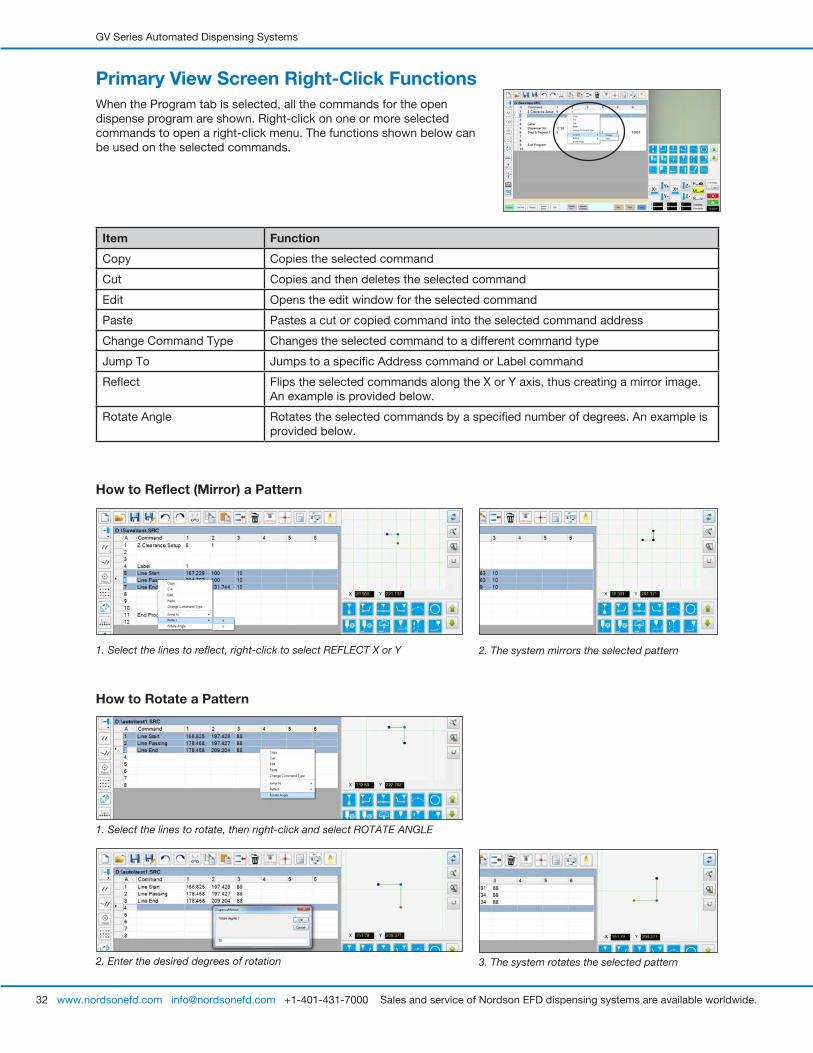
Primary View Screen Right-Click FunctionsWhen the Program tab is selected, all the commands for the open dispense program are shown. Right-click on one or more selected commands to open a right-click menu. The functions shown below can be used on the selected commands.
Item Function
Copy Copies the selected command
Cut Copies and then deletes the selected command
Edit Opens the edit window for the selected command
Paste Pastes a cut or copied command into the selected command address
Change Command Type Changes the selected command to a different command type
Jump To Jumps to a specific Address command or Label command
Reflect Flips the selected commands along the X or Y axis, thus creating a mirror image. An example is provided below.
Rotate Angle Rotates the selected commands by a specified number of degrees. An example is provided below.
How to Reflect (Mirror) a Pattern
1. Select the lines to reflect, right-click to select REFLECT X or Y 2. The system mirrors the selected pattern
How to Rotate a Pattern
1. Select the lines to rotate, then right-click and select ROTATE ANGLE
2. Enter the desired degrees of rotation 3. The system rotates the selected pattern
GV Series Automated Dispensing Systems
33www.nordsonefd.com [email protected] +1-401-431-7000 Sales and service of Nordson EFD dispensing systems are available worldwide.
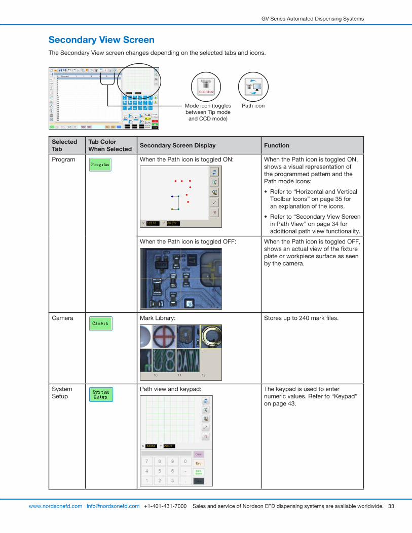
Secondary View ScreenThe Secondary View screen changes depending on the selected tabs and icons.
Selected Tab
Tab Color When Selected Secondary Screen Display Function
Program When the Path icon is toggled ON: When the Path icon is toggled ON, shows a visual representation of the programmed pattern and the Path mode icons:
• Refer to “Horizontal and Vertical Toolbar Icons” on page 35 for an explanation of the icons.
• Refer to “Secondary View Screen in Path View” on page 34 for additional path view functionality.
When the Path icon is toggled OFF: When the Path icon is toggled OFF, shows an actual view of the fixture plate or workpiece surface as seen by the camera.
Camera Mark Library: Stores up to 240 mark files.
System Setup
Path view and keypad: The keypad is used to enter numeric values. Refer to “Keypad” on page 43.
Path iconMode icon (toggles between Tip mode
and CCD mode)
GV Series Automated Dispensing Systems
34 www.nordsonefd.com [email protected] +1-401-431-7000 Sales and service of Nordson EFD dispensing systems are available worldwide.
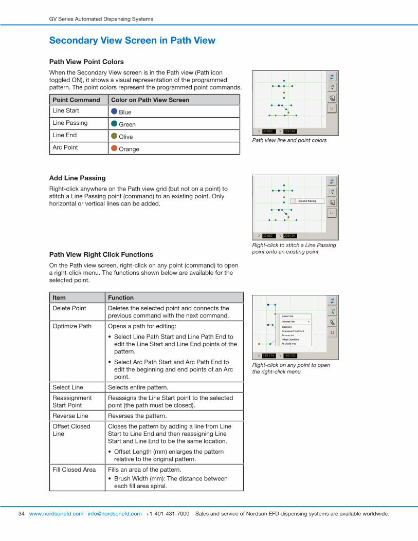
Secondary View Screen in Path View
Path View Point Colors
When the Secondary View screen is in the Path view (Path icon toggled ON), it shows a visual representation of the programmed pattern. The point colors represent the programmed point commands.
Point Command Color on Path View Screen
Line Start Blue
Line Passing Green
Line End Olive
Arc Point Orange
Path View Right Click Functions
On the Path view screen, right-click on any point (command) to open a right-click menu. The functions shown below are available for the selected point.
Path view line and point colors
Right-click on any point to open the right-click menu
Item Function
Delete Point Deletes the selected point and connects the previous command with the next command.
Optimize Path Opens a path for editing:
• Select Line Path Start and Line Path End to edit the Line Start and Line End points of the pattern.
• Select Arc Path Start and Arc Path End to edit the beginning and end points of an Arc point.
Select Line Selects entire pattern.
Reassignment Start Point
Reassigns the Line Start point to the selected point (the path must be closed).
Reverse Line Reverses the pattern.
Offset Closed Line
Closes the pattern by adding a line from Line Start to Line End and then reassigning Line Start and Line End to be the same location.
• Offset Length (mm) enlarges the pattern relative to the original pattern.
Fill Closed Area Fills an area of the pattern.
• Brush Width (mm): The distance between each fill area spiral.
Add Line Passing
Right-click anywhere on the Path view grid (but not on a point) to stitch a Line Passing point (command) to an existing point. Only horizontal or vertical lines can be added.
Right-click to stitch a Line Passing point onto an existing point
GV Series Automated Dispensing Systems
35www.nordsonefd.com [email protected] +1-401-431-7000 Sales and service of Nordson EFD dispensing systems are available worldwide.
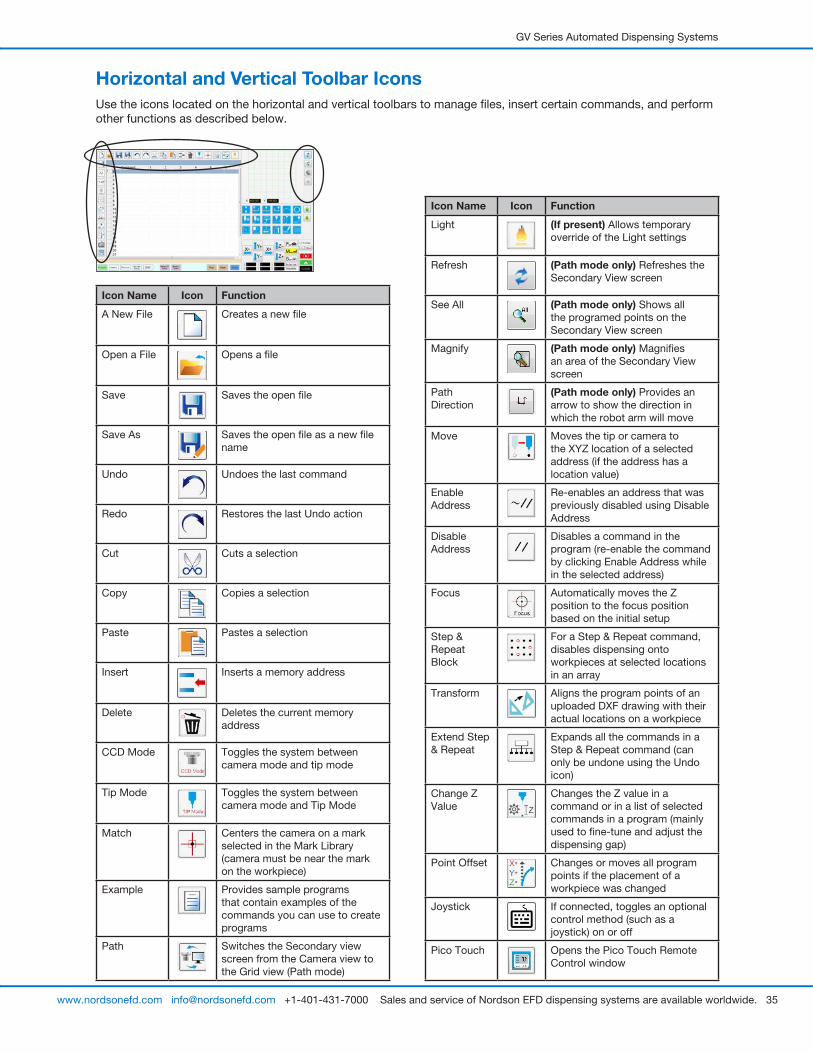
Horizontal and Vertical Toolbar IconsUse the icons located on the horizontal and vertical toolbars to manage files, insert certain commands, and perform other functions as described below.
Icon Name Icon Function
A New File Creates a new file
Open a File Opens a file
Save Saves the open file
Save As Saves the open file as a new file name
Undo Undoes the last command
Redo Restores the last Undo action
Cut Cuts a selection
Copy Copies a selection
Paste Pastes a selection
Insert Inserts a memory address
Delete Deletes the current memory address
CCD Mode Toggles the system between camera mode and tip mode
Tip Mode Toggles the system between camera mode and Tip Mode
Match Centers the camera on a mark selected in the Mark Library (camera must be near the mark on the workpiece)
Example Provides sample programs that contain examples of the commands you can use to create programs
Path Switches the Secondary view screen from the Camera view to the Grid view (Path mode)
Icon Name Icon Function
Light (If present) Allows temporary override of the Light settings
Refresh (Path mode only) Refreshes the Secondary View screen
See All (Path mode only) Shows all the programed points on the Secondary View screen
Magnify (Path mode only) Magnifies an area of the Secondary View screen
Path Direction
(Path mode only) Provides an arrow to show the direction in which the robot arm will move
Move Moves the tip or camera to the XYZ location of a selected address (if the address has a location value)
Enable Address
Re-enables an address that was previously disabled using Disable Address
Disable Address
Disables a command in the program (re-enable the command by clicking Enable Address while in the selected address)
Focus Automatically moves the Z position to the focus position based on the initial setup
Step & Repeat Block
For a Step & Repeat command, disables dispensing onto workpieces at selected locations in an array
Transform Aligns the program points of an uploaded DXF drawing with their actual locations on a workpiece
Extend Step & Repeat
Expands all the commands in a Step & Repeat command (can only be undone using the Undo icon)
Change Z Value
Changes the Z value in a command or in a list of selected commands in a program (mainly used to fine-tune and adjust the dispensing gap)
Point Offset Changes or moves all program points if the placement of a workpiece was changed
Joystick If connected, toggles an optional control method (such as a joystick) on or off
Pico Touch Opens the Pico Touch Remote Control window
GV Series Automated Dispensing Systems
36 www.nordsonefd.com [email protected] +1-401-431-7000 Sales and service of Nordson EFD dispensing systems are available worldwide.
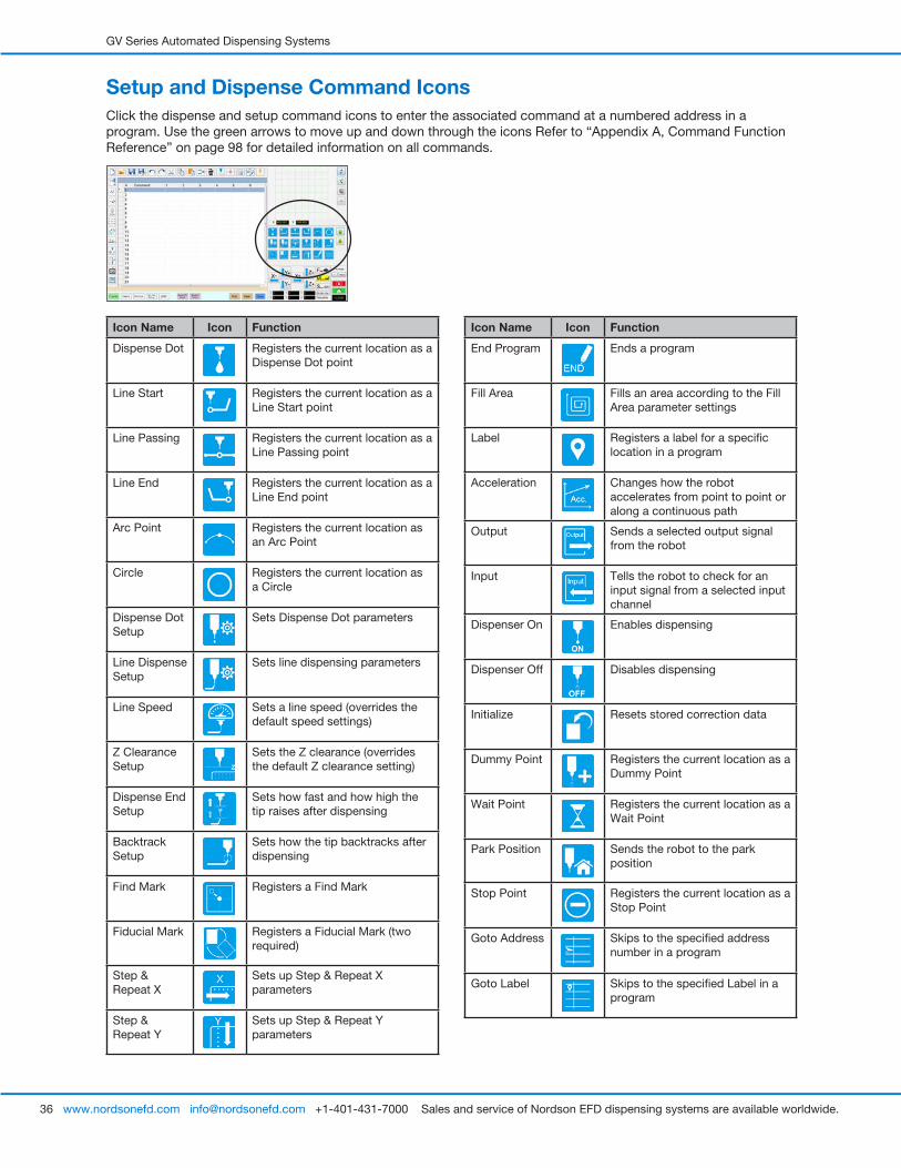
Setup and Dispense Command IconsClick the dispense and setup command icons to enter the associated command at a numbered address in a program. Use the green arrows to move up and down through the icons Refer to “Appendix A, Command Function Reference” on page 98 for detailed information on all commands.
Icon Name Icon Function
End Program Ends a program
Fill Area Fills an area according to the Fill Area parameter settings
Label Registers a label for a specific location in a program
Acceleration Changes how the robot accelerates from point to point or along a continuous path
Output Sends a selected output signal from the robot
Input Tells the robot to check for an input signal from a selected input channel
Dispenser On Enables dispensing
Dispenser Off Disables dispensing
Initialize Resets stored correction data
Dummy Point Registers the current location as a Dummy Point
Wait Point Registers the current location as a Wait Point
Park Position Sends the robot to the park position
Stop Point Registers the current location as a Stop Point
Goto Address Skips to the specified address number in a program
Goto Label Skips to the specified Label in a program
Icon Name Icon Function
Dispense Dot Registers the current location as a Dispense Dot point
Line Start Registers the current location as a Line Start point
Line Passing Registers the current location as a Line Passing point
Line End Registers the current location as a Line End point
Arc Point Registers the current location as an Arc Point
Circle Registers the current location as a Circle
Dispense Dot Setup
Sets Dispense Dot parameters
Line Dispense Setup
Sets line dispensing parameters
Line Speed Sets a line speed (overrides the default speed settings)
Z Clearance Setup
Sets the Z clearance (overrides the default Z clearance setting)
Dispense End Setup
Sets how fast and how high the tip raises after dispensing
Backtrack Setup
Sets how the tip backtracks after dispensing
Find Mark Registers a Find Mark
Fiducial Mark Registers a Fiducial Mark (two required)
Step & Repeat X
Sets up Step & Repeat X parameters
Step & Repeat Y
Sets up Step & Repeat Y parameters
GV Series Automated Dispensing Systems
37www.nordsonefd.com [email protected] +1-401-431-7000 Sales and service of Nordson EFD dispensing systems are available worldwide.
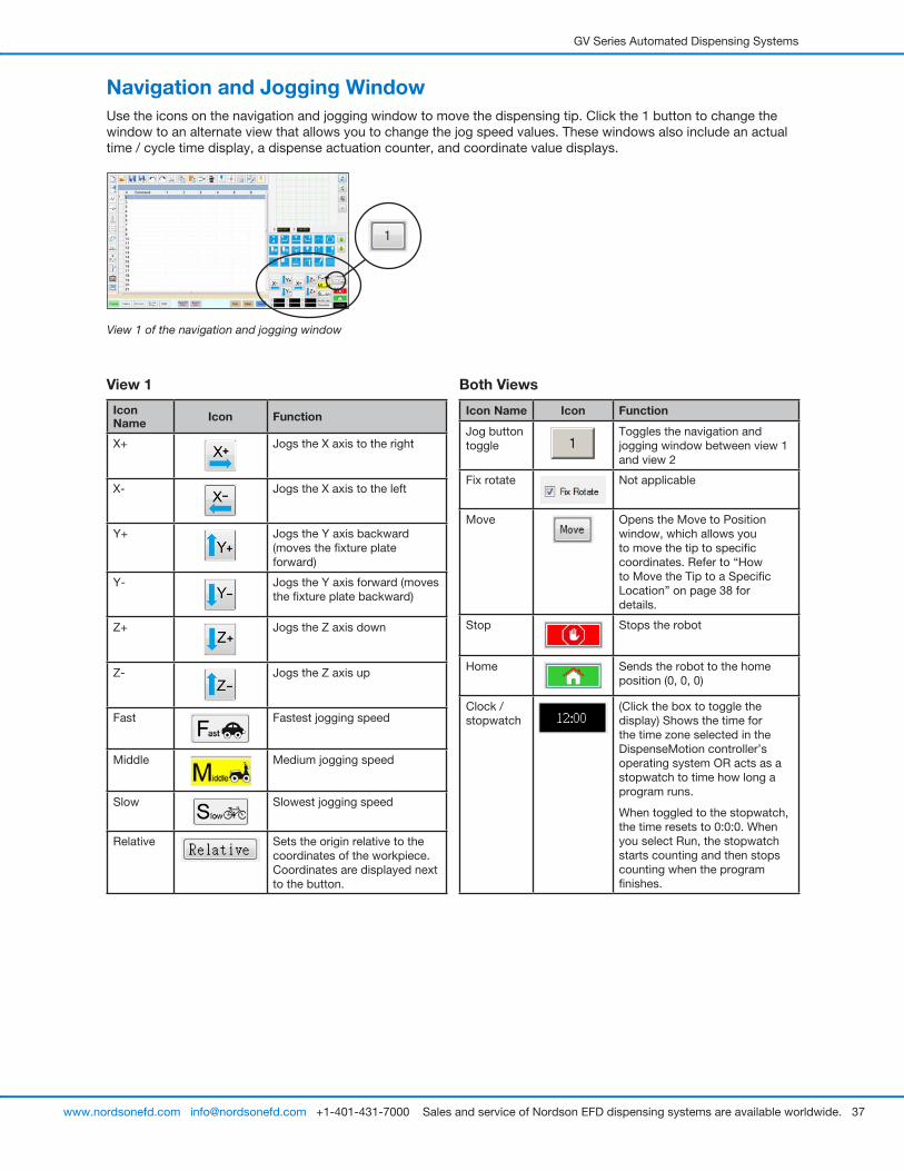
Navigation and Jogging WindowUse the icons on the navigation and jogging window to move the dispensing tip. Click the 1 button to change the window to an alternate view that allows you to change the jog speed values. These windows also include an actual time / cycle time display, a dispense actuation counter, and coordinate value displays.
View 1
Icon Name Icon Function
X+ Jogs the X axis to the right
X- Jogs the X axis to the left
Y+ Jogs the Y axis backward (moves the fixture plate forward)
Y- Jogs the Y axis forward (moves the fixture plate backward)
Z+ Jogs the Z axis down
Z- Jogs the Z axis up
Fast Fastest jogging speed
Middle Medium jogging speed
Slow Slowest jogging speed
Relative Sets the origin relative to the coordinates of the workpiece. Coordinates are displayed next to the button.
Both Views
Icon Name Icon Function
Jog button toggle
Toggles the navigation and jogging window between view 1 and view 2
Fix rotate Not applicable
Move Opens the Move to Position window, which allows you to move the tip to specific coordinates. Refer to “How to Move the Tip to a Specific Location” on page 38 for details.
Stop Stops the robot
Home Sends the robot to the home position (0, 0, 0)
Clock / stopwatch
(Click the box to toggle the display) Shows the time for the time zone selected in the DispenseMotion controller’s operating system OR acts as a stopwatch to time how long a program runs.
When toggled to the stopwatch, the time resets to 0:0:0. When you select Run, the stopwatch starts counting and then stops counting when the program finishes.
View 1 of the navigation and jogging window
GV Series Automated Dispensing Systems
38 www.nordsonefd.com [email protected] +1-401-431-7000 Sales and service of Nordson EFD dispensing systems are available worldwide.
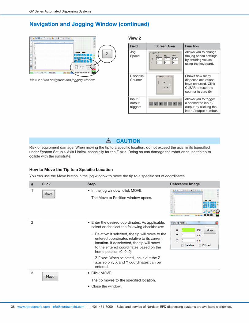
View 2
Field Screen Area Function
Jog Speed
Allows you to change the jog speed settings by entering values using the keyboard.
Dispense Counter
Shows how many dispense actuations have occurred. Click CLEAR to reset the counter to zero (0).
Input / output triggers
Allows you to trigger a connected input / output by clicking the input / output number.
Navigation and Jogging Window (continued)
View 2 of the navigation and jogging window
CAUTIONRisk of equipment damage. When moving the tip to a specific location, do not exceed the axis limits (specified under System Setup > Axis Limits), especially for the Z axis. Doing so can damage the robot or cause the tip to collide with the substrate.
How to Move the Tip to a Specific Location
You can use the Move button in the jog window to move the tip to a specific set of coordinates.
# Click Step Reference Image
1 • In the jog window, click MOVE.
The Move to Position window opens.
2 • Enter the desired coordinates. As applicable, select or deselect the following checkboxes:
- Relative: If selected, the tip will move to the entered coordinates relative to its current location. If deselected, the tip will move to the entered coordinates based on the home position (0, 0, 0).
- Z Fixed: When selected, locks out the Z axis so only X and Y coordinates can be entered.
3 • Click MOVE.
The tip moves to the specified location.
• Close the window.
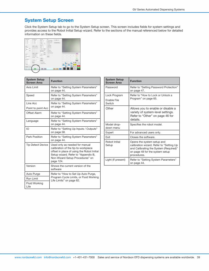
GV Series Automated Dispensing Systems
39www.nordsonefd.com [email protected] +1-401-431-7000 Sales and service of Nordson EFD dispensing systems are available worldwide.
System Setup ScreenClick the System Setup tab to go to the System Setup screen. This screen includes fields for system settings and provides access to the Robot Initial Setup wizard. Refer to the sections of the manual referenced below for detailed information on these fields.
System Setup Screen Area Function
Axis Limit Refer to “Setting System Parameters” on page 44.
Speed Refer to “Setting System Parameters” on page 44.
Line Acc
Point to point Acc
Refer to “Setting System Parameters” on page 44.
Offset Alarm Refer to “Setting System Parameters” on page 44.
Language Refer to “Setting System Parameters” on page 44.
IO Refer to “Setting Up Inputs / Outputs” on page 58.
Park Position Refer to “Setting System Parameters” on page 44.
Tip Detect Device Used only as needed for manual calibration of the tip-to-workpiece offset in place of using the Robot Initial Setup wizard. Refer to “Appendix B, Non-Wizard Setup Procedures” on page 124.
Version Shows the current version of the software
Auto Purge Refer to “How to Set Up Auto Purge, Program Cycle Limits, or Fluid Working Life Limits” on page 82.
Run Limit
Fluid Working Life
System Setup Screen Area Function
Password Refer to “Setting Password Protection” on page 47.
Lock Program
Enable File Switch
Refer to “How to Lock or Unlock a Program” on page 65.
Other Allows you to enable or disable a variety of system-level settings. Refer to “Other” on page 46 for details.
Model drop-down menu
Specifies the robot model.
Expert For advanced users only.
Exit Closes the software.
Robot Initial Setup
Opens the system setup and calibration wizard. Refer to “Setting Up and Calibrating the System (Required)” on page 48 for the system setup procedures.
Light (If present) Refer to “Setting System Parameters” on page 44.

GV Series Automated Dispensing Systems
40 www.nordsonefd.com [email protected] +1-401-431-7000 Sales and service of Nordson EFD dispensing systems are available worldwide.
Camera Screen, Tab Bar, and IconsClick the CAMERA tab to go to the Camera screen. The actual view of what the camera sees appears in the Primary View screen and the Mark Library appears in the Secondary View screen. The tabs at the top of the Camera screen are used for camera setup and mark creation.
Camera Screen Tab Function
Center Moves the camera focal point to the center of an object
Set Mark Sets a mark. Refer to “About Marks” on page 28 and to “How to Create a Mark” on page 70.
Cancel Cancels the last camera-related action
Range Sets the area within which the system searches for a mark
Scale Scales the screen to match the camera view scale (occurs during setup)
Stop Find Stops the attempt to find a mark
Setup Opens the Camera Setup window that provides access to important setup fields related to the camera. Refer to “Camera Setup Screen” on page 43.
Lens Opens the Camera Properties window. Refer to “Camera Properties Window” on page 41 for details.
Icon Name Icon Function
Measure Length
Measures the distance between two points. Refer to “How to Measure a Path or Circle on a Workpiece” on page 65.
Measure Circle Diameter
Measures the diameter of a circle. Refer to “How to Measure a Path or Circle on a Workpiece” on page 65.
Arrow Accesses advanced functionality for deposit verification using the optional OptiSure™ add-on software. This icon is enabled only when the OptiSure add-on is unlocked.
Refer to “OptiSure Software Key” on page 91 for the OptiSure kit part number. Refer to the OptiSure manual for operating instructions.
Touch Move When toggled, moves the camera to the point clicked and moves the focal point to the center of the viewing screen
Save Saves the displayed camera image as a bitmap (*.bmp) file
CCD Focus Automatically moves the Z axis to the focus position established during Robot Initial Setup (Step 5 or 6), or as defined in the camera setup window (under Offset)
Primary View screen shows the actual camera view when the Camera tab is selected
Secondary View screen shows the Mark Library when the Camera tab is selected
Right-click on any image and then select PROPERTY to open the Template Match window. Refer to “Template Match and Area Windows” on page 42 for information about this window.
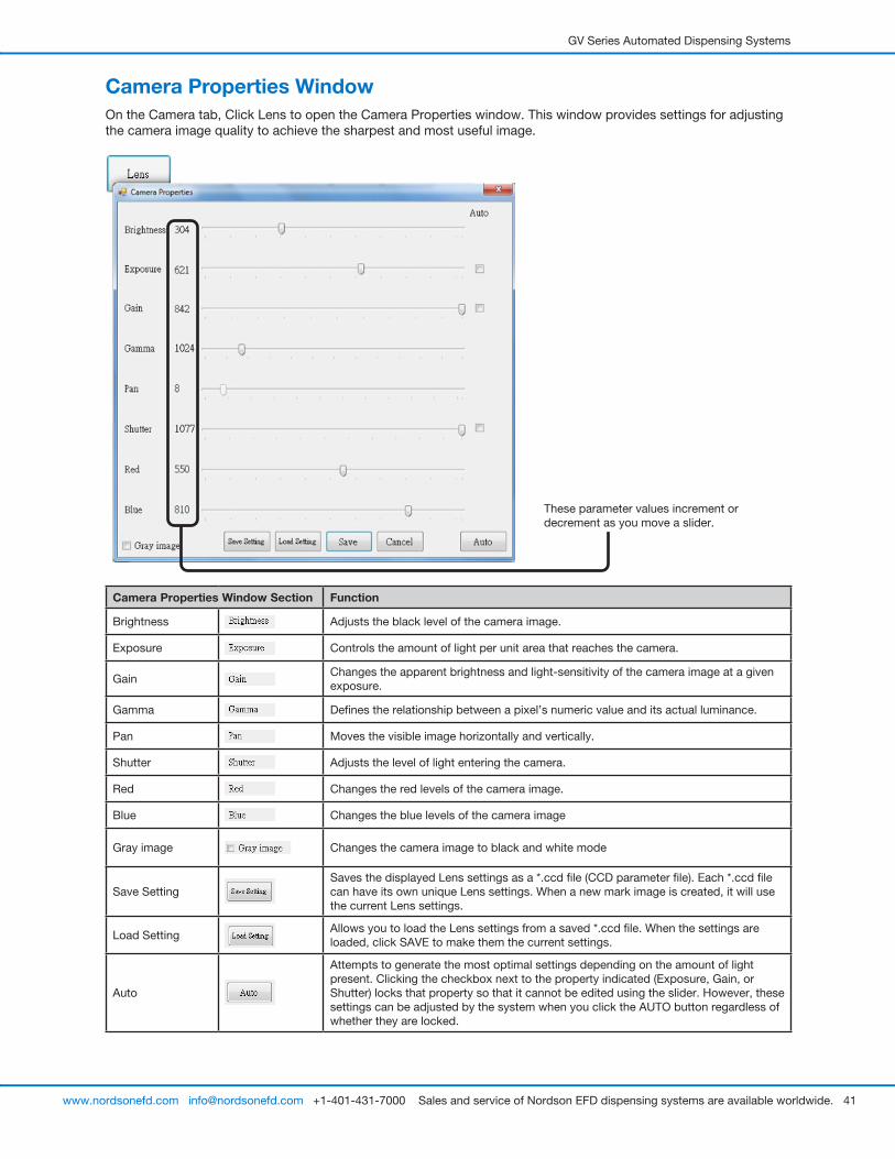
GV Series Automated Dispensing Systems
41www.nordsonefd.com [email protected] +1-401-431-7000 Sales and service of Nordson EFD dispensing systems are available worldwide.
Camera Properties WindowOn the Camera tab, Click Lens to open the Camera Properties window. This window provides settings for adjusting the camera image quality to achieve the sharpest and most useful image.
These parameter values increment or decrement as you move a slider.
Camera Properties Window Section Function
Brightness Adjusts the black level of the camera image.
Exposure Controls the amount of light per unit area that reaches the camera.
GainChanges the apparent brightness and light-sensitivity of the camera image at a given exposure.
Gamma Defines the relationship between a pixel’s numeric value and its actual luminance.
Pan Moves the visible image horizontally and vertically.
Shutter Adjusts the level of light entering the camera.
Red Changes the red levels of the camera image.
Blue Changes the blue levels of the camera image
Gray image Changes the camera image to black and white mode
Save SettingSaves the displayed Lens settings as a *.ccd file (CCD parameter file). Each *.ccd file can have its own unique Lens settings. When a new mark image is created, it will use the current Lens settings.
Load SettingAllows you to load the Lens settings from a saved *.ccd file. When the settings are loaded, click SAVE to make them the current settings.
Auto
Attempts to generate the most optimal settings depending on the amount of light present. Clicking the checkbox next to the property indicated (Exposure, Gain, or Shutter) locks that property so that it cannot be edited using the slider. However, these settings can be adjusted by the system when you click the AUTO button regardless of whether they are locked.
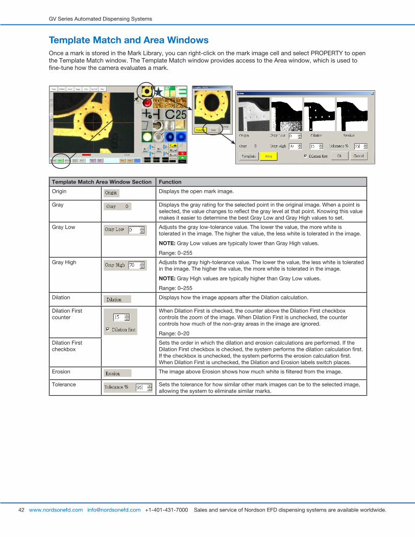
GV Series Automated Dispensing Systems
42 www.nordsonefd.com [email protected] +1-401-431-7000 Sales and service of Nordson EFD dispensing systems are available worldwide.
Template Match and Area WindowsOnce a mark is stored in the Mark Library, you can right-click on the mark image cell and select PROPERTY to open the Template Match window. The Template Match window provides access to the Area window, which is used to fine-tune how the camera evaluates a mark.
Template Match Area Window Section Function
Origin Displays the open mark image.
Gray Displays the gray rating for the selected point in the original image. When a point is selected, the value changes to reflect the gray level at that point. Knowing this value makes it easier to determine the best Gray Low and Gray High values to set.
Gray Low Adjusts the gray low-tolerance value. The lower the value, the more white is tolerated in the image. The higher the value, the less white is tolerated in the image.
NOTE: Gray Low values are typically lower than Gray High values.
Range: 0–255
Gray High Adjusts the gray high-tolerance value. The lower the value, the less white is tolerated in the image. The higher the value, the more white is tolerated in the image.
NOTE: Gray High values are typically higher than Gray Low values.
Range: 0–255
Dilation Displays how the image appears after the Dilation calculation.
Dilation First counter
When Dilation First is checked, the counter above the Dilation First checkbox controls the zoom of the image. When Dilation First is unchecked, the counter controls how much of the non-gray areas in the image are ignored.
Range: 0–20
Dilation First checkbox
Sets the order in which the dilation and erosion calculations are performed. If the Dilation First checkbox is checked, the system performs the dilation calculation first. If the checkbox is unchecked, the system performs the erosion calculation first. When Dilation First is unchecked, the Dilation and Erosion labels switch places.
Erosion The image above Erosion shows how much white is filtered from the image.
Tolerance Sets the tolerance for how similar other mark images can be to the selected image, allowing the system to eliminate similar marks.
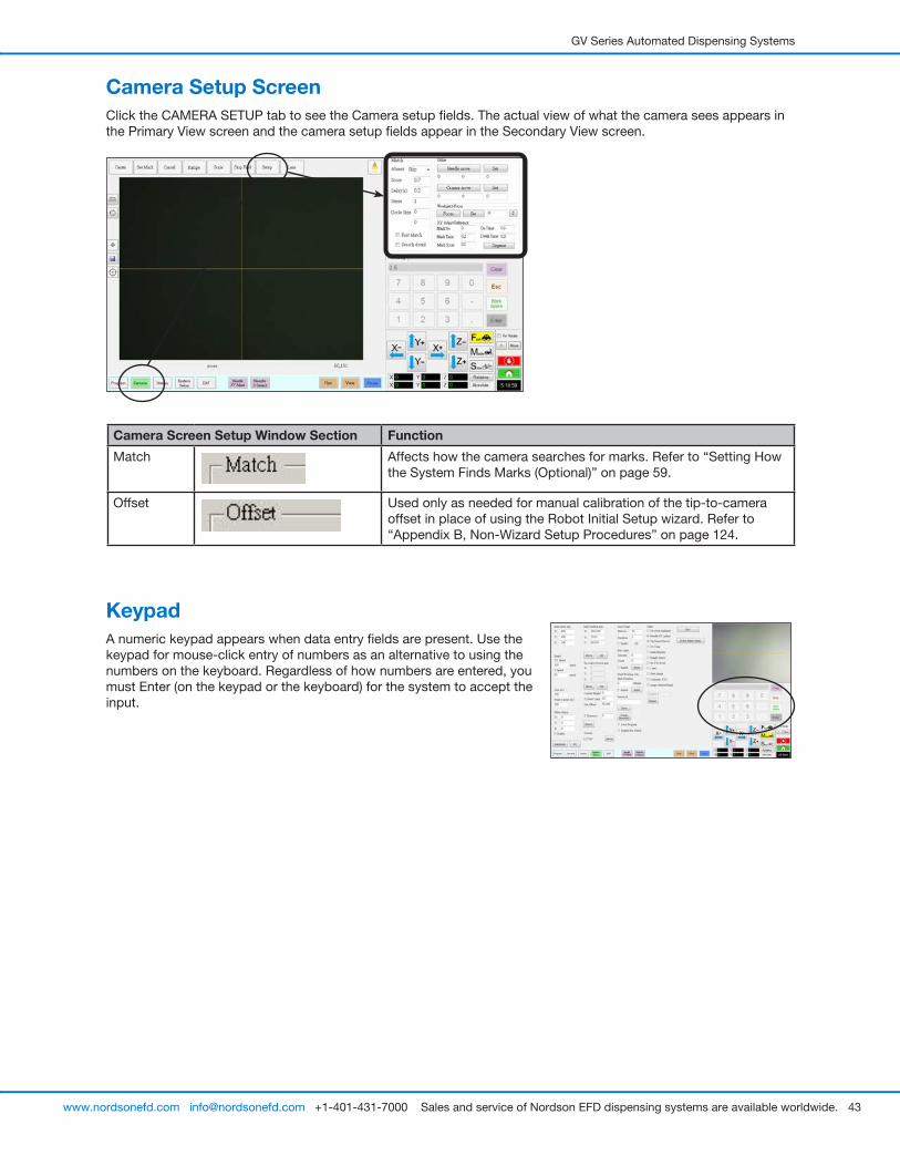
GV Series Automated Dispensing Systems
43www.nordsonefd.com [email protected] +1-401-431-7000 Sales and service of Nordson EFD dispensing systems are available worldwide.
Camera Setup ScreenClick the CAMERA SETUP tab to see the Camera setup fields. The actual view of what the camera sees appears in the Primary View screen and the camera setup fields appear in the Secondary View screen.
Camera Screen Setup Window Section Function
Match Affects how the camera searches for marks. Refer to “Setting How the System Finds Marks (Optional)” on page 59.
Offset Used only as needed for manual calibration of the tip-to-camera offset in place of using the Robot Initial Setup wizard. Refer to “Appendix B, Non-Wizard Setup Procedures” on page 124.
KeypadA numeric keypad appears when data entry fields are present. Use the keypad for mouse-click entry of numbers as an alternative to using the numbers on the keyboard. Regardless of how numbers are entered, you must Enter (on the keypad or the keyboard) for the system to accept the input.
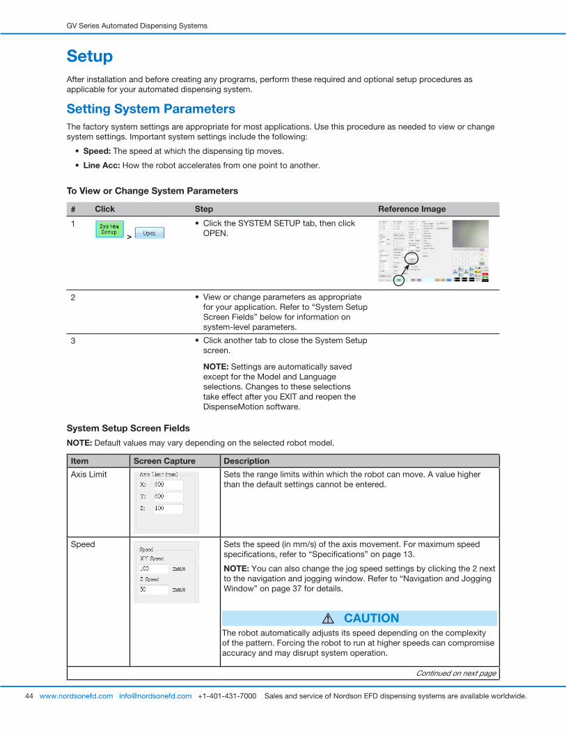
GV Series Automated Dispensing Systems
44 www.nordsonefd.com [email protected] +1-401-431-7000 Sales and service of Nordson EFD dispensing systems are available worldwide.
SetupAfter installation and before creating any programs, perform these required and optional setup procedures as applicable for your automated dispensing system.
System Setup Screen Fields
NOTE: Default values may vary depending on the selected robot model.
Item Screen Capture Description
Axis Limit Sets the range limits within which the robot can move. A value higher than the default settings cannot be entered.
Speed Sets the speed (in mm/s) of the axis movement. For maximum speed specifications, refer to “Specifications” on page 13.
NOTE: You can also change the jog speed settings by clicking the 2 next to the navigation and jogging window. Refer to “Navigation and Jogging Window” on page 37 for details.
CAUTIONThe robot automatically adjusts its speed depending on the complexity of the pattern. Forcing the robot to run at higher speeds can compromise accuracy and may disrupt system operation.
Continued on next page
Setting System ParametersThe factory system settings are appropriate for most applications. Use this procedure as needed to view or change system settings. Important system settings include the following:
• Speed: The speed at which the dispensing tip moves.
• Line Acc: How the robot accelerates from one point to another.
To View or Change System Parameters
# Click Step Reference Image
1
>
• Click the SYSTEM SETUP tab, then click OPEN.
2 • View or change parameters as appropriate for your application. Refer to “System Setup Screen Fields” below for information on system-level parameters.
3 • Click another tab to close the System Setup screen.
NOTE: Settings are automatically saved except for the Model and Language selections. Changes to these selections take effect after you EXIT and reopen the DispenseMotion software.
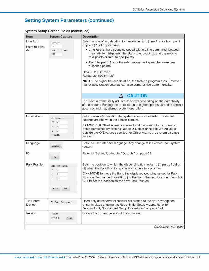
GV Series Automated Dispensing Systems
45www.nordsonefd.com [email protected] +1-401-431-7000 Sales and service of Nordson EFD dispensing systems are available worldwide.
Item Screen Capture Description
Line Acc
Point to point Acc
Sets the rate of acceleration for line dispensing (Line Acc) or from point to point (Point to point Acc):
• Line Acc is the dispensing speed within a line command, between the start- to mid-points, the start- to end-points, and the mid- to mid-points or mid- to end-points.
• Point to point Acc is the robot movement speed between two dispense points.
Default: 200 (mm/s2) Range: 20–600 (mm/s2)
NOTE: The higher the acceleration, the faster a program runs. However, higher acceleration settings can also compromise pattern quality.
CAUTIONThe robot automatically adjusts its speed depending on the complexity of the pattern. Forcing the robot to run at higher speeds can compromise accuracy and may disrupt system operation.
Offset Alarm Sets how much deviation the system allows for offsets. The default settings are shown in the screen capture.
EXAMPLE: If Offset Alarm is enabled and the result of an automatic offset performed by clicking Needle Z Detect or Needle XY Adjust is outside the XYZ values specified for Offset Alarm, the system displays an alarm.
Language Sets the user interface language. Any change takes effect upon system restart.
IO Refer to “Setting Up Inputs / Outputs” on page 58.
Park Position Sets the position to which the dispensing tip moves to (1) purge fluid or (2) when the Park Position command occurs in a program.
Click MOVE to move the tip to the displayed coordinates set for Park Position. To change the setting, jog the tip to the new location, then click SET to set the location as the new Park Position.
Tip Detect Device
Used only as needed for manual calibration of the tip-to-workpiece offset in place of using the Robot Initial Setup wizard. Refer to “Appendix B, Non-Wizard Setup Procedures” on page 124.
Version Shows the current version of the software.
Continued on next page
Setting System Parameters (continued)
System Setup Screen Fields (continued)
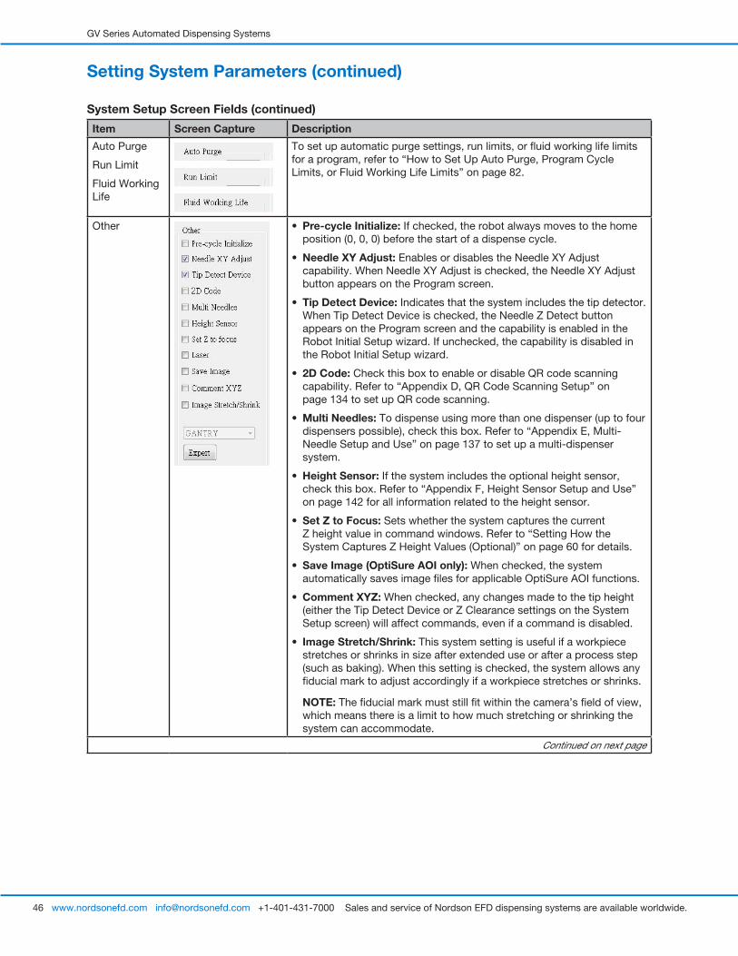
GV Series Automated Dispensing Systems
46 www.nordsonefd.com [email protected] +1-401-431-7000 Sales and service of Nordson EFD dispensing systems are available worldwide.
Setting System Parameters (continued)
System Setup Screen Fields (continued)
Item Screen Capture Description
Auto Purge
Run Limit
Fluid Working Life
To set up automatic purge settings, run limits, or fluid working life limits for a program, refer to “How to Set Up Auto Purge, Program Cycle Limits, or Fluid Working Life Limits” on page 82.
Other • Pre-cycle Initialize: If checked, the robot always moves to the home position (0, 0, 0) before the start of a dispense cycle.
• Needle XY Adjust: Enables or disables the Needle XY Adjust capability. When Needle XY Adjust is checked, the Needle XY Adjust button appears on the Program screen.
• Tip Detect Device: Indicates that the system includes the tip detector. When Tip Detect Device is checked, the Needle Z Detect button appears on the Program screen and the capability is enabled in the Robot Initial Setup wizard. If unchecked, the capability is disabled in the Robot Initial Setup wizard.
• 2D Code: Check this box to enable or disable QR code scanning capability. Refer to “Appendix D, QR Code Scanning Setup” on page 134 to set up QR code scanning.
• Multi Needles: To dispense using more than one dispenser (up to four dispensers possible), check this box. Refer to “Appendix E, Multi-Needle Setup and Use” on page 137 to set up a multi-dispenser system.
• Height Sensor: If the system includes the optional height sensor, check this box. Refer to “Appendix F, Height Sensor Setup and Use” on page 142 for all information related to the height sensor.
• Set Z to Focus: Sets whether the system captures the current Z height value in command windows. Refer to “Setting How the System Captures Z Height Values (Optional)” on page 60 for details.
• Save Image (OptiSure AOI only): When checked, the system automatically saves image files for applicable OptiSure AOI functions.
• Comment XYZ: When checked, any changes made to the tip height (either the Tip Detect Device or Z Clearance settings on the System Setup screen) will affect commands, even if a command is disabled.
• Image Stretch/Shrink: This system setting is useful if a workpiece stretches or shrinks in size after extended use or after a process step (such as baking). When this setting is checked, the system allows any fiducial mark to adjust accordingly if a workpiece stretches or shrinks.
NOTE: The fiducial mark must still fit within the camera’s field of view, which means there is a limit to how much stretching or shrinking the system can accommodate.
Continued on next page
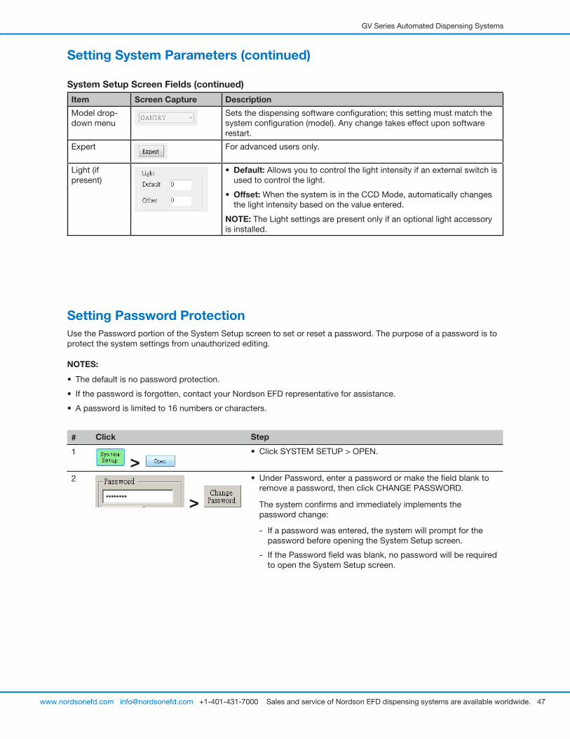
GV Series Automated Dispensing Systems
47www.nordsonefd.com [email protected] +1-401-431-7000 Sales and service of Nordson EFD dispensing systems are available worldwide.
Setting Password ProtectionUse the Password portion of the System Setup screen to set or reset a password. The purpose of a password is to protect the system settings from unauthorized editing.
NOTES:
• The default is no password protection.
• If the password is forgotten, contact your Nordson EFD representative for assistance.
• A password is limited to 16 numbers or characters.
# Click Step
1
> • Click SYSTEM SETUP > OPEN.
2
>
• Under Password, enter a password or make the field blank to remove a password, then click CHANGE PASSWORD.
The system confirms and immediately implements the password change:
- If a password was entered, the system will prompt for the password before opening the System Setup screen.
- If the Password field was blank, no password will be required to open the System Setup screen.
Item Screen Capture Description
Model drop-down menu
Sets the dispensing software configuration; this setting must match the system configuration (model). Any change takes effect upon software restart.
Expert For advanced users only.
Light (if present)
• Default: Allows you to control the light intensity if an external switch is used to control the light.
• Offset: When the system is in the CCD Mode, automatically changes the light intensity based on the value entered.
NOTE: The Light settings are present only if an optional light accessory is installed.
Setting System Parameters (continued)
System Setup Screen Fields (continued)
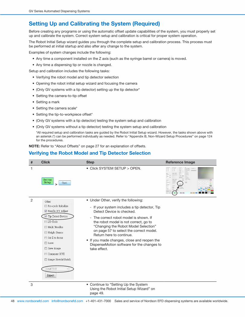
GV Series Automated Dispensing Systems
48 www.nordsonefd.com [email protected] +1-401-431-7000 Sales and service of Nordson EFD dispensing systems are available worldwide.
Setting Up and Calibrating the System (Required)Before creating any programs or using the automatic offset update capabilities of the system, you must properly set up and calibrate the system. Correct system setup and calibration is critical for proper system operation.
The Robot Initial Setup wizard guides you through the complete setup and calibration process. This process must be performed at initial startup and also after any change to the system.
Examples of system changes include the following:
• Any time a component installed on the Z axis (such as the syringe barrel or camera) is moved.
• Any time a dispensing tip or nozzle is changed.
Setup and calibration includes the following tasks:
• Verifying the robot model and tip detector selection
• Opening the robot initial setup wizard and focusing the camera
• (Only GV systems with a tip detector) setting up the tip detector*
• Setting the camera-to-tip offset
• Setting a mark
• Setting the camera scale*
• Setting the tip-to-workpiece offset*
• (Only GV systems with a tip detector) testing the system setup and calibration
• (Only GV systems without a tip detector) testing the system setup and calibration
*All required setup and calibration tasks are guided by the Robot Initial Setup wizard. However, the tasks shown above with an asterisk (*) can be performed individually as needed. Refer to “Appendix B, Non-Wizard Setup Procedures” on page 124 for the procedures.
NOTE: Refer to “About Offsets” on page 27 for an explanation of offsets.
Verifying the Robot Model and Tip Detector Selection
# Click Step Reference Image
1
>
• Click SYSTEM SETUP > OPEN.
2 • Under Other, verify the following:
- If your system includes a tip detector, Tip Detect Device is checked.
- The correct robot model is shown. If the robot model is not correct, go to “Changing the Robot Model Selection” on page 57 to select the correct model. Return here to continue.
• If you made changes, close and reopen the DispenseMotion software for the changes to take effect.
3 • Continue to “Setting Up the System Using the Robot Initial Setup Wizard” on page 49.
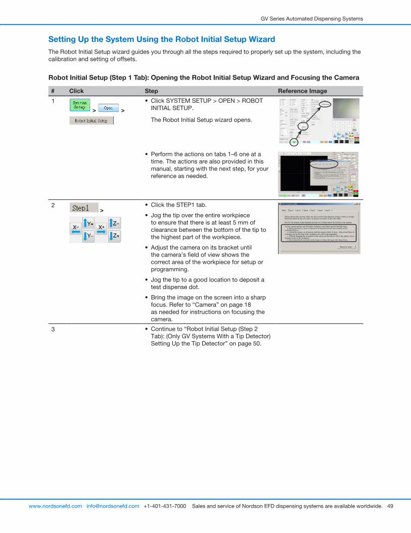
GV Series Automated Dispensing Systems
49www.nordsonefd.com [email protected] +1-401-431-7000 Sales and service of Nordson EFD dispensing systems are available worldwide.
Setting Up the System Using the Robot Initial Setup WizardThe Robot Initial Setup wizard guides you through all the steps required to properly set up the system, including the calibration and setting of offsets.
Robot Initial Setup (Step 1 Tab): Opening the Robot Initial Setup Wizard and Focusing the Camera
# Click Step Reference Image
1
> >
• Click SYSTEM SETUP > OPEN > ROBOT INITIAL SETUP.
The Robot Initial Setup wizard opens.
• Perform the actions on tabs 1–6 one at a time. The actions are also provided in this manual, starting with the next step, for your reference as needed.
2 >
• Click the STEP1 tab.
• Jog the tip over the entire workpiece to ensure that there is at least 5 mm of clearance between the bottom of the tip to the highest part of the workpiece.
• Adjust the camera on its bracket until the camera’s field of view shows the correct area of the workpiece for setup or programming.
• Jog the tip to a good location to deposit a test dispense dot.
• Bring the image on the screen into a sharp focus. Refer to “Camera” on page 18 as needed for instructions on focusing the camera.
3 • Continue to “Robot Initial Setup (Step 2 Tab): (Only GV Systems With a Tip Detector) Setting Up the Tip Detector” on page 50.
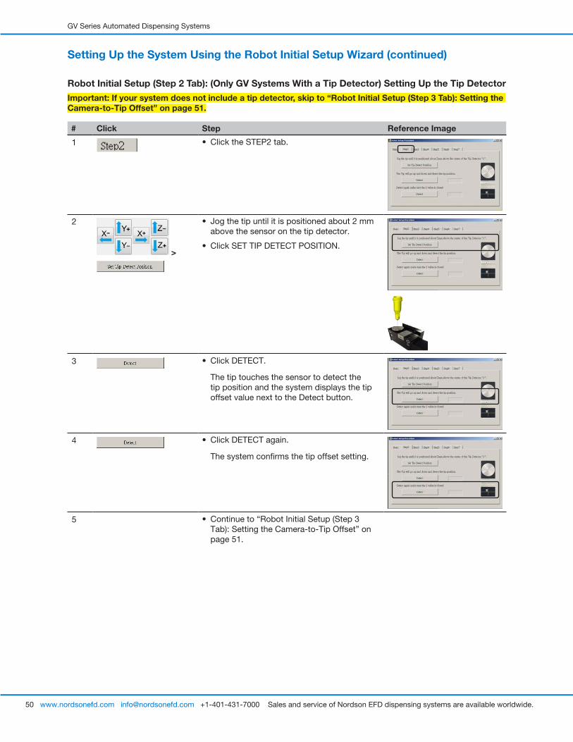
GV Series Automated Dispensing Systems
50 www.nordsonefd.com [email protected] +1-401-431-7000 Sales and service of Nordson EFD dispensing systems are available worldwide.
Robot Initial Setup (Step 2 Tab): (Only GV Systems With a Tip Detector) Setting Up the Tip Detector
Important: If your system does not include a tip detector, skip to “Robot Initial Setup (Step 3 Tab): Setting the Camera-to-Tip Offset” on page 51.
# Click Step Reference Image
1 • Click the STEP2 tab.
2
>
• Jog the tip until it is positioned about 2 mm above the sensor on the tip detector.
• Click SET TIP DETECT POSITION.
3 • Click DETECT.
The tip touches the sensor to detect the tip position and the system displays the tip offset value next to the Detect button.
4 • Click DETECT again.
The system confirms the tip offset setting.
5 • Continue to “Robot Initial Setup (Step 3 Tab): Setting the Camera-to-Tip Offset” on page 51.
Setting Up the System Using the Robot Initial Setup Wizard (continued)
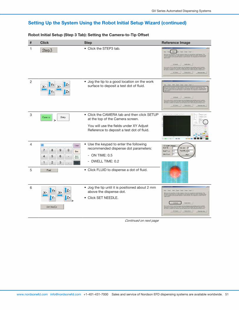
GV Series Automated Dispensing Systems
51www.nordsonefd.com [email protected] +1-401-431-7000 Sales and service of Nordson EFD dispensing systems are available worldwide.
Robot Initial Setup (Step 3 Tab): Setting the Camera-to-Tip Offset
# Click Step Reference Image
1 • Click the STEP3 tab.
2 • Jog the tip to a good location on the work surface to deposit a test dot of fluid.
3
>
• Click the CAMERA tab and then click SETUP at the top of the Camera screen.
You will use the fields under XY Adjust Reference to deposit a test dot of fluid.
4 • Use the keypad to enter the following recommended dispense dot parameters:
- ON TIME: 0.5
- DWELL TIME: 0.2
5 • Click FLUID to dispense a dot of fluid.
6
>
• Jog the tip until it is positioned about 2 mm above the dispense dot.
• Click SET NEEDLE.
Continued on next page
Setting Up the System Using the Robot Initial Setup Wizard (continued)
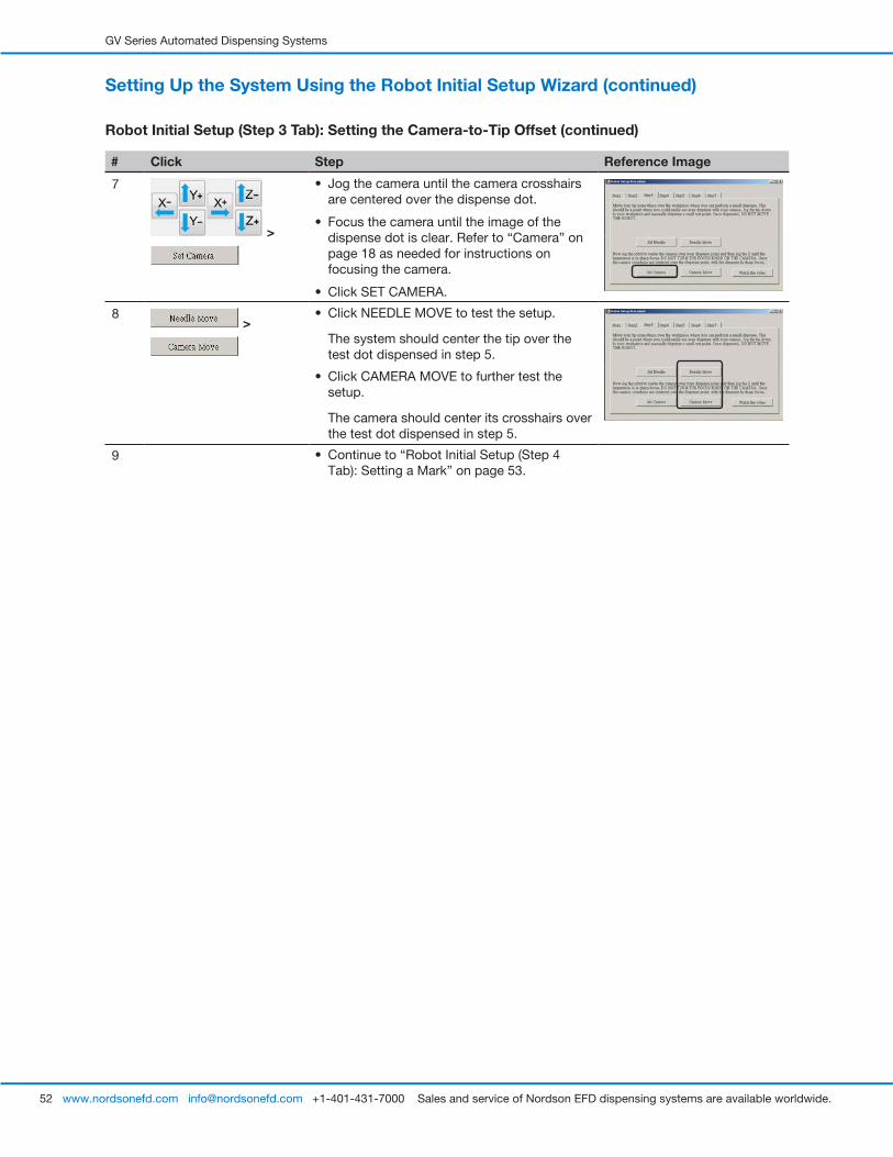
GV Series Automated Dispensing Systems
52 www.nordsonefd.com [email protected] +1-401-431-7000 Sales and service of Nordson EFD dispensing systems are available worldwide.
Setting Up the System Using the Robot Initial Setup Wizard (continued)
Robot Initial Setup (Step 3 Tab): Setting the Camera-to-Tip Offset (continued)
# Click Step Reference Image
7
>
• Jog the camera until the camera crosshairs are centered over the dispense dot.
• Focus the camera until the image of the dispense dot is clear. Refer to “Camera” on page 18 as needed for instructions on focusing the camera.
• Click SET CAMERA.
8 >
• Click NEEDLE MOVE to test the setup.
The system should center the tip over the test dot dispensed in step 5.
• Click CAMERA MOVE to further test the setup.
The camera should center its crosshairs over the test dot dispensed in step 5.
9 • Continue to “Robot Initial Setup (Step 4 Tab): Setting a Mark” on page 53.
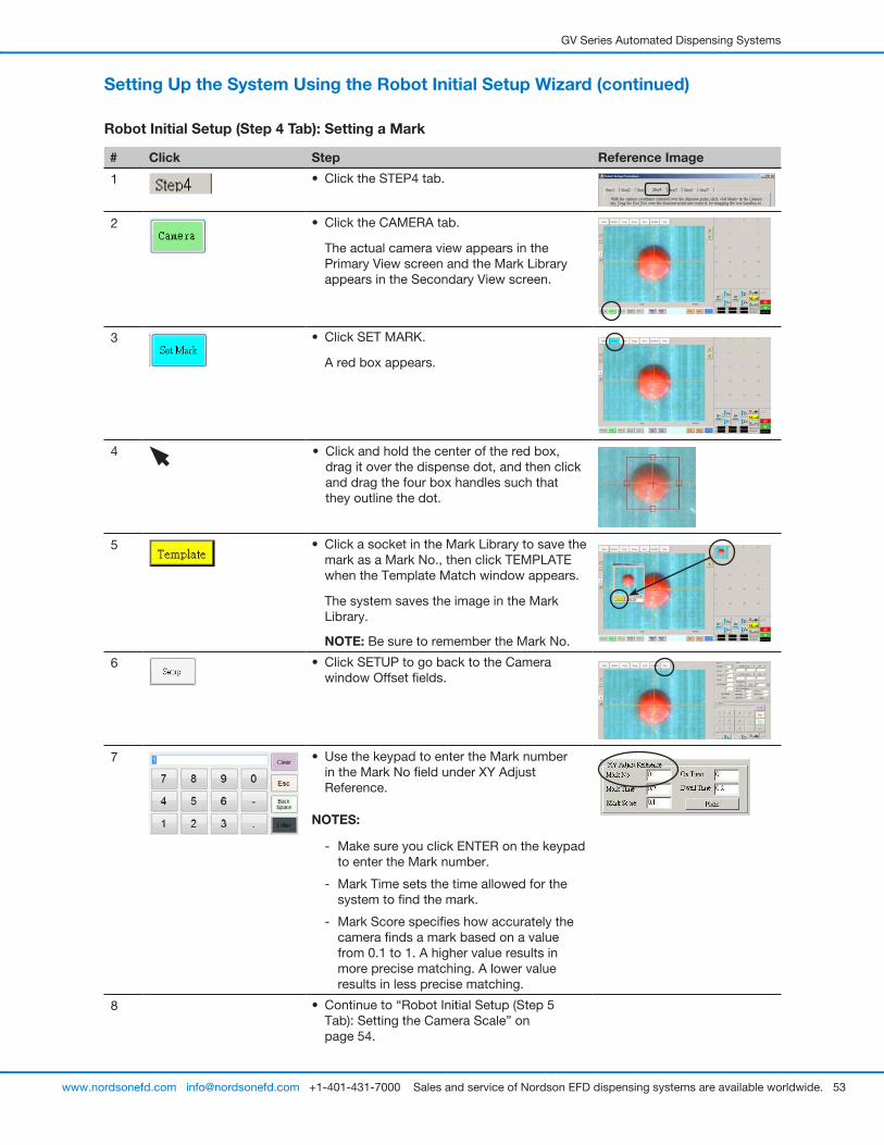
GV Series Automated Dispensing Systems
53www.nordsonefd.com [email protected] +1-401-431-7000 Sales and service of Nordson EFD dispensing systems are available worldwide.
Setting Up the System Using the Robot Initial Setup Wizard (continued)
Robot Initial Setup (Step 4 Tab): Setting a Mark
# Click Step Reference Image
1 • Click the STEP4 tab.
2 • Click the CAMERA tab.
The actual camera view appears in the Primary View screen and the Mark Library appears in the Secondary View screen.
3 • Click SET MARK.
A red box appears.
4 • Click and hold the center of the red box, drag it over the dispense dot, and then click and drag the four box handles such that they outline the dot.
5 • Click a socket in the Mark Library to save the mark as a Mark No., then click TEMPLATE when the Template Match window appears.
The system saves the image in the Mark Library.
NOTE: Be sure to remember the Mark No.
6 • Click SETUP to go back to the Camera window Offset fields.
7 • Use the keypad to enter the Mark number in the Mark No field under XY Adjust Reference.
NOTES:
- Make sure you click ENTER on the keypad to enter the Mark number.
- Mark Time sets the time allowed for the system to find the mark.
- Mark Score specifies how accurately the camera finds a mark based on a value from 0.1 to 1. A higher value results in more precise matching. A lower value results in less precise matching.
8 • Continue to “Robot Initial Setup (Step 5 Tab): Setting the Camera Scale” on page 54.

GV Series Automated Dispensing Systems
54 www.nordsonefd.com [email protected] +1-401-431-7000 Sales and service of Nordson EFD dispensing systems are available worldwide.
Setting Up the System Using the Robot Initial Setup Wizard (continued)
Robot Initial Setup (Step 5 Tab): Setting the Camera Scale
# Click Step Reference Image
1 • Click the STEP5 tab.
2 • Click the CAMERA tab.
3 • Jog the camera to a point of reference that is located on the lower right corner of the workpiece.
• Bring the reference point into focus. Refer to “Camera” on page 18 as needed for instructions on focusing the camera.
4
>
• Click the CAMERA tab and then click SCALE.
The Scale window opens.
NOTE: When the camera views an object, it converts the pixels to a true measurement. For the camera to make this conversion accurately, you must “teach” the camera what the size of an object is in comparison to pixels per inch by setting the camera scale.
5 • Choose a point of reference on the workpiece and jog the camera so that the reference point is located in the lower right quadrant of the camera screen, then click the point.
6 • Jog the camera again until the same reference point is located in the upper left quadrant of the camera screen, then click the point.
The camera scale is now set.
7 • Continue to “Robot Initial Setup (Step 6 Tab): Setting the Tip-to-Workpiece Offset” on page 55.
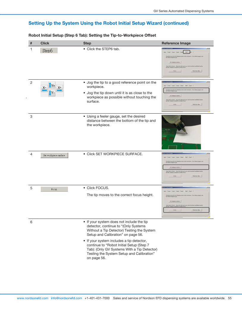
GV Series Automated Dispensing Systems
55www.nordsonefd.com [email protected] +1-401-431-7000 Sales and service of Nordson EFD dispensing systems are available worldwide.
Setting Up the System Using the Robot Initial Setup Wizard (continued)
Robot Initial Setup (Step 6 Tab): Setting the Tip-to-Workpiece Offset
# Click Step Reference Image
1 • Click the STEP6 tab.
2 • Jog the tip to a good reference point on the workpiece.
• Jog the tip down until it is as close to the workpiece as possible without touching the surface.
3 • Using a feeler gauge, set the desired distance between the bottom of the tip and the workpiece.
4 • Click SET WORKPIECE SURFACE.
5 • Click FOCUS.
The tip moves to the correct focus height.
6 • If your system does not include the tip detector, continue to “(Only Systems Without a Tip Detector) Testing the System Setup and Calibration” on page 56.
• If your system includes a tip detector, continue to “Robot Initial Setup (Step 7 Tab): (Only GV Systems With a Tip Detector) Testing the System Setup and Calibration” on page 56.

GV Series Automated Dispensing Systems
56 www.nordsonefd.com [email protected] +1-401-431-7000 Sales and service of Nordson EFD dispensing systems are available worldwide.
Setting Up the System Using the Robot Initial Setup Wizard (continued)
Robot Initial Setup (Step 7 Tab): (Only GV Systems With a Tip Detector) Testing the System Setup and Calibration
Important: If your system does not include a tip detector, skip to “(Only Systems Without a Tip Detector) Testing the System Setup and Calibration”.
# Click Step Reference Image
1 • Click the STEP7 tab.
2 • Click NEEDLE Z DETECT to test the setup.
• Click YES/OK when prompted for confirmations.
NOTES:
- When the system performs a Needle Z Detect, it automatically performs a Needle XY Adjust directly after performing the Needle Z Detect.
- Refer to “How the System Responds to Needle Z Detect or Needle XY Adjust” on page 57 for a detailed description of the system response to a Needle Z Detect selection.
3 >
• Click SAVE.
• Click FINISH.
The system is now properly set up and calibrated. Refer to “Programming” on page 63 to create programs.
(Only Systems Without a Tip Detector) Testing the System Setup and Calibration
# Click Step
1 SYSTEMS WITHOUT A TIP DETECTOR:
• Click NEEDLE XY ADJUST to test the setup.
• Click YES/OK when prompted for confirmations.
Refer to “How the System Responds to Needle Z Detect or Needle XY Adjust” on page 57 for a detailed description of the system response to a Needle XY Adjust selection.
The system is now properly set up and calibrated. Refer to “Programming” on page 63 to create programs.

GV Series Automated Dispensing Systems
57www.nordsonefd.com [email protected] +1-401-431-7000 Sales and service of Nordson EFD dispensing systems are available worldwide.
How the System Responds to Needle Z Detect or Needle XY AdjustNOTE: On systems with the optional tip detector, both the Needle XY Adjust and Needle Z Detect buttons are present. On systems without the optional tip detector, only the Needle XY Adjust button is present.
When you click NEEDLE Z DETECT, the system performs the following actions:• Moves the dispensing tip over the tip detector sensor and lowers it until it touches the sensor.
• Measures and compares the difference between the last measurement and the current measurement.
• Requests confirmation for any change in the tip-to-workpiece offset (Z clearance).
• Realigns all points in the currently open program to the new tip-to-workpiece offset (Z clearance).
• Automatically performs a Needle XY Adjust sequence (shown below).
When you click NEEDLE XY ADJUST, the system performs the following actions:• Moves the dispensing tip to a preset location on the workpiece.
• Dispenses a dot of fluid.
• Moves the camera over the deposited dot of fluid.
• Compares the alignment of the dot with the mark image saved in the Mark Library.
• Requests confirmation for any change in the camera-to-tip offset (XY offsets).
• Realigns all points in the currently open program to the new XY offsets.
Changing the Robot Model SelectionThe correct robot model must be selected for the system to operate properly. Follow this procedure to change the robot model selection as needed.
# Click Step Reference Image
1
> >
• Click SYSTEM SETUP > OPEN > EXPERT.
2 11111111 >
• Enter 11111111, then click OK.
3 • Click CONTROL.
Continued on next page
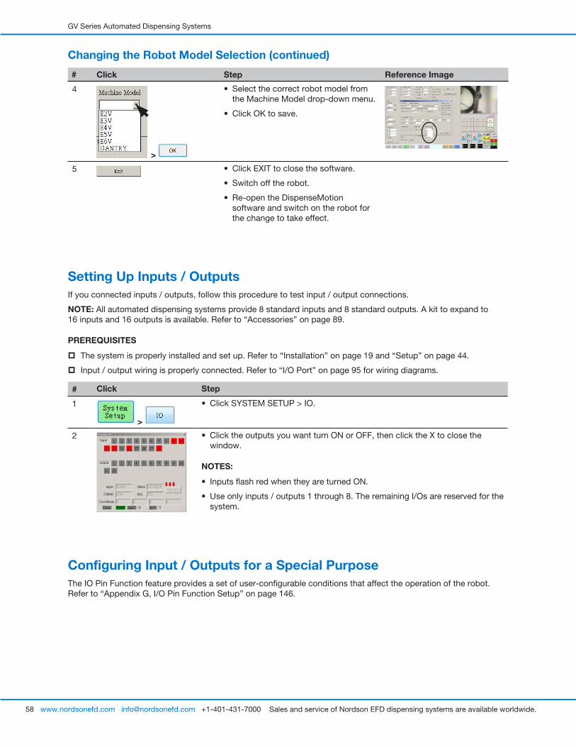
GV Series Automated Dispensing Systems
58 www.nordsonefd.com [email protected] +1-401-431-7000 Sales and service of Nordson EFD dispensing systems are available worldwide.
Setting Up Inputs / OutputsIf you connected inputs / outputs, follow this procedure to test input / output connections.
NOTE: All automated dispensing systems provide 8 standard inputs and 8 standard outputs. A kit to expand to 16 inputs and 16 outputs is available. Refer to “Accessories” on page 89.
PREREQUISITES
� The system is properly installed and set up. Refer to “Installation” on page 19 and “Setup” on page 44.
� Input / output wiring is properly connected. Refer to “I/O Port” on page 95 for wiring diagrams.
# Click Step
1
>
• Click SYSTEM SETUP > IO.
2 • Click the outputs you want turn ON or OFF, then click the X to close the window.
NOTES:
• Inputs flash red when they are turned ON.
• Use only inputs / outputs 1 through 8. The remaining I/Os are reserved for the system.
Configuring Input / Outputs for a Special PurposeThe IO Pin Function feature provides a set of user-configurable conditions that affect the operation of the robot. Refer to “Appendix G, I/O Pin Function Setup” on page 146.
Changing the Robot Model Selection (continued)
# Click Step Reference Image
4
>
• Select the correct robot model from the Machine Model drop-down menu.
• Click OK to save.
5 • Click EXIT to close the software.
• Switch off the robot.
• Re-open the DispenseMotion software and switch on the robot for the change to take effect.
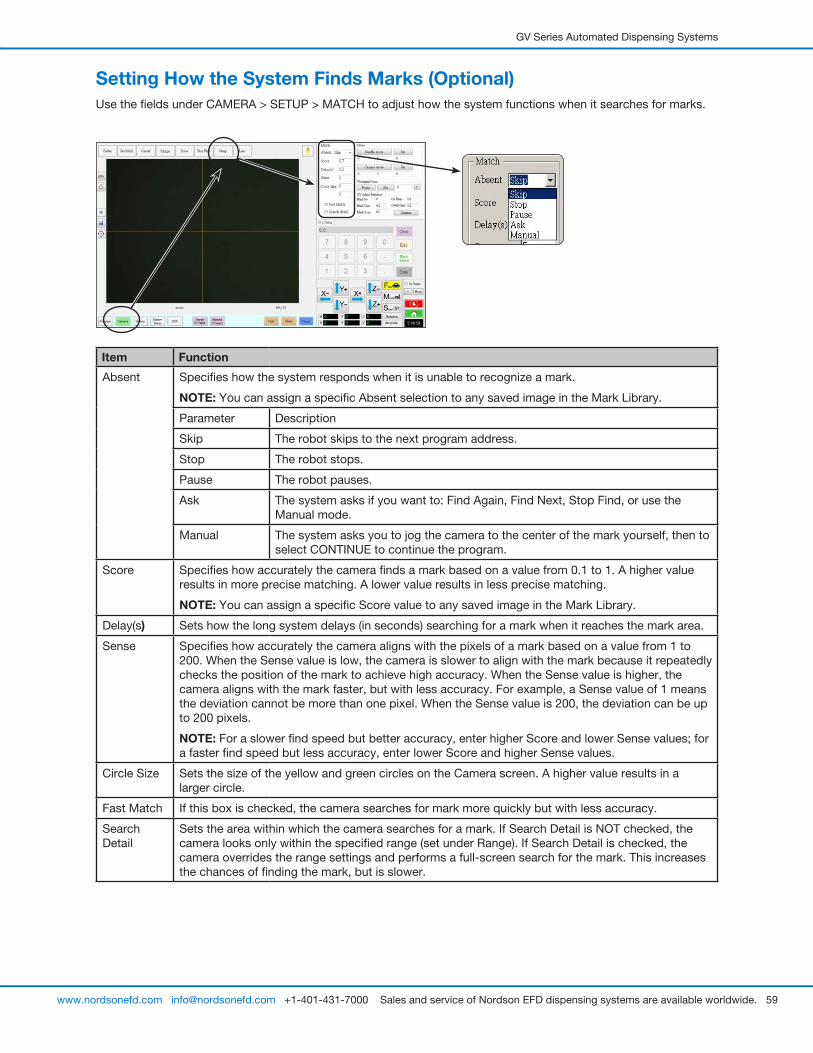
GV Series Automated Dispensing Systems
59www.nordsonefd.com [email protected] +1-401-431-7000 Sales and service of Nordson EFD dispensing systems are available worldwide.
Item Function
Absent Specifies how the system responds when it is unable to recognize a mark.
NOTE: You can assign a specific Absent selection to any saved image in the Mark Library.
Parameter Description
Skip The robot skips to the next program address.
Stop The robot stops.
Pause The robot pauses.
Ask The system asks if you want to: Find Again, Find Next, Stop Find, or use the Manual mode.
Manual The system asks you to jog the camera to the center of the mark yourself, then to select CONTINUE to continue the program.
Score Specifies how accurately the camera finds a mark based on a value from 0.1 to 1. A higher value results in more precise matching. A lower value results in less precise matching.
NOTE: You can assign a specific Score value to any saved image in the Mark Library.
Delay(s) Sets how the long system delays (in seconds) searching for a mark when it reaches the mark area.
Sense Specifies how accurately the camera aligns with the pixels of a mark based on a value from 1 to 200. When the Sense value is low, the camera is slower to align with the mark because it repeatedly checks the position of the mark to achieve high accuracy. When the Sense value is higher, the camera aligns with the mark faster, but with less accuracy. For example, a Sense value of 1 means the deviation cannot be more than one pixel. When the Sense value is 200, the deviation can be up to 200 pixels.
NOTE: For a slower find speed but better accuracy, enter higher Score and lower Sense values; for a faster find speed but less accuracy, enter lower Score and higher Sense values.
Circle Size Sets the size of the yellow and green circles on the Camera screen. A higher value results in a larger circle.
Fast Match If this box is checked, the camera searches for mark more quickly but with less accuracy.
Search Detail
Sets the area within which the camera searches for a mark. If Search Detail is NOT checked, the camera looks only within the specified range (set under Range). If Search Detail is checked, the camera overrides the range settings and performs a full-screen search for the mark. This increases the chances of finding the mark, but is slower.
Setting How the System Finds Marks (Optional)Use the fields under CAMERA > SETUP > MATCH to adjust how the system functions when it searches for marks.

GV Series Automated Dispensing Systems
60 www.nordsonefd.com [email protected] +1-401-431-7000 Sales and service of Nordson EFD dispensing systems are available worldwide.
Setting How the System Captures Z Height Values (Optional)By default, the system does not capture the Z-height value as you move the camera over the work surface. This is a safeguard to prevent the dispensing tip from being damaged when a workpiece surface is uneven.
Use the Set Z to Focus checkbox in the Expert window to set the system to automatically capture Z-height values.
# Click Step Reference Image
1
>
• Click SYSTEM SETUP > OPEN.
2 CAUTIONWhen SET Z TO FOCUS is NOT checked, the tip can collide with obstacles on uneven workpieces, causing damage.
• Select or deselect the SET Z TO FOCUS checkbox.
When SET Z TO FOCUS is checked, the system captures Z-height values.
3 • Click EXIT to close, then reopen the DispenseMotion software for the change to take effect.
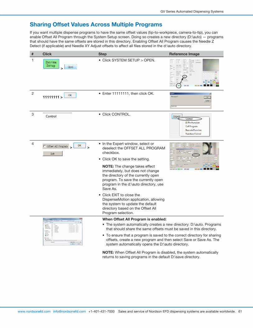
GV Series Automated Dispensing Systems
61www.nordsonefd.com [email protected] +1-401-431-7000 Sales and service of Nordson EFD dispensing systems are available worldwide.
Sharing Offset Values Across Multiple ProgramsIf you want multiple dispense programs to have the same offset values (tip-to-workpiece, camera-to-tip), you can enable Offset All Program through the System Setup screen. Doing so creates a new directory (D:\auto) — programs that should have the same offsets are stored in this directory. Enabling Offset All Program causes the Needle Z Detect (if applicable) and Needle XY Adjust offsets to affect all files stored in the d:\auto directory.
# Click Step Reference Image
1
>
• Click SYSTEM SETUP > OPEN.
2 11111111 >
• Enter 11111111, then click OK.
3 • Click CONTROL.
4 > >
• In the Expert window, select or deselect the OFFSET ALL PROGRAM checkbox.
• Click OK to save the setting.
NOTE: The change takes effect immediately, but does not change the directory of the currently open program. To save the currently open program in the d:\auto directory, use Save As.
• Click EXIT to close the DispenseMotion application, allowing the system to update the default directory based on the Offset All Program selection.
When Offset All Program is enabled:• The system automatically creates a new directory: D:\auto. Programs
that should share the same offsets must be saved in this directory.
• To ensure that a program is saved to the correct directory for sharing offsets, create a new program and then select Save or Save As. The system automatically opens the D:\auto directory.
NOTE: When Offset All Program is disabled, the system automatically returns to saving programs in the default D:\save directory.
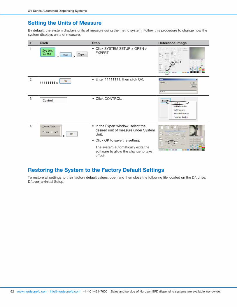
GV Series Automated Dispensing Systems
62 www.nordsonefd.com [email protected] +1-401-431-7000 Sales and service of Nordson EFD dispensing systems are available worldwide.
Setting the Units of MeasureBy default, the system displays units of measure using the metric system. Follow this procedure to change how the system displays units of measure.
# Click Step Reference Image
1
> >
• Click SYSTEM SETUP > OPEN > EXPERT.
2 11111111 >
• Enter 11111111, then click OK.
3 • Click CONTROL.
4
>
• In the Expert window, select the desired unit of measure under System Unit.
• Click OK to save the setting.
The system automatically exits the software to allow the change to take effect.
Restoring the System to the Factory Default SettingsTo restore all settings to their factory default values, open and then close the following file located on the D:\ drive: D:\ever_sr\Initial Setup.

GV Series Automated Dispensing Systems
63www.nordsonefd.com [email protected] +1-401-431-7000 Sales and service of Nordson EFD dispensing systems are available worldwide.
ProgrammingThis section provides how-to procedures for the most commonly performed programming tasks. Refer to “How to Create and Run a Program” for an example of how to use the dispensing software to create a complete program. If you have difficulty creating a program for your application, contact your Nordson EFD representative. Before using this section:
• Complete all applicable installation tasks. Refer to “Installation” on page 19.
• Complete all required setup tasks. Refer to “Setup” on page 44.
• Refer to “Concepts” on page 26 for important robot programming concepts and for an overview of the dispensing software screens and icons.
How to Create and Run a ProgramThe procedure provides the basic steps for creating and running a program. Every program is different. Use these basic steps and refer to “How to Create Patterns” on page 66 and “Appendix A, Command Function Reference” on page 98 to create the desired application pattern for the workpiece or group of workpieces.
PREREQUISITES
� The system is properly set up. Refer to “Setting Up and Calibrating the System (Required)” on page 48.
� If the tip or any element of the Z axis head was changed, repeat system setup and calibration using the Robot Initial Setup wizard. Refer to “Setting Up the System Using the Robot Initial Setup Wizard” on page 49.
� The system is in the correct mode (Tip or CCD).
� A workpiece is properly positioned on the fixture plate.
# Click Step
1 • Click the PROGRAM tab.
Address 1 is available to insert a command.
2 • Jog the dispensing tip to a desired XYZ location by clicking the navigation icons.
3 • Insert a setup or dispense command that tells the robot what to do. Click a command icon, or double-click anywhere in the address line to select a command from the drop-down menu.
4 • Edit the command parameter settings. Refer to the following sections of this manual for information to help you create programs:
- “About Programs and Commands” on page 26 (includes best practices)
- “How to Create Patterns” on page 66
- “How to Create a Mark” on page 70
- “Appendix A, Command Function Reference” on page 98 (provides detailed information on all commands)
5 • Repeat steps 2 through 4 until the program is complete.
6 • To delete a command, click the command and then click the Delete icon.
7 • Click END PROGRAM to end the program.
Continued on next page
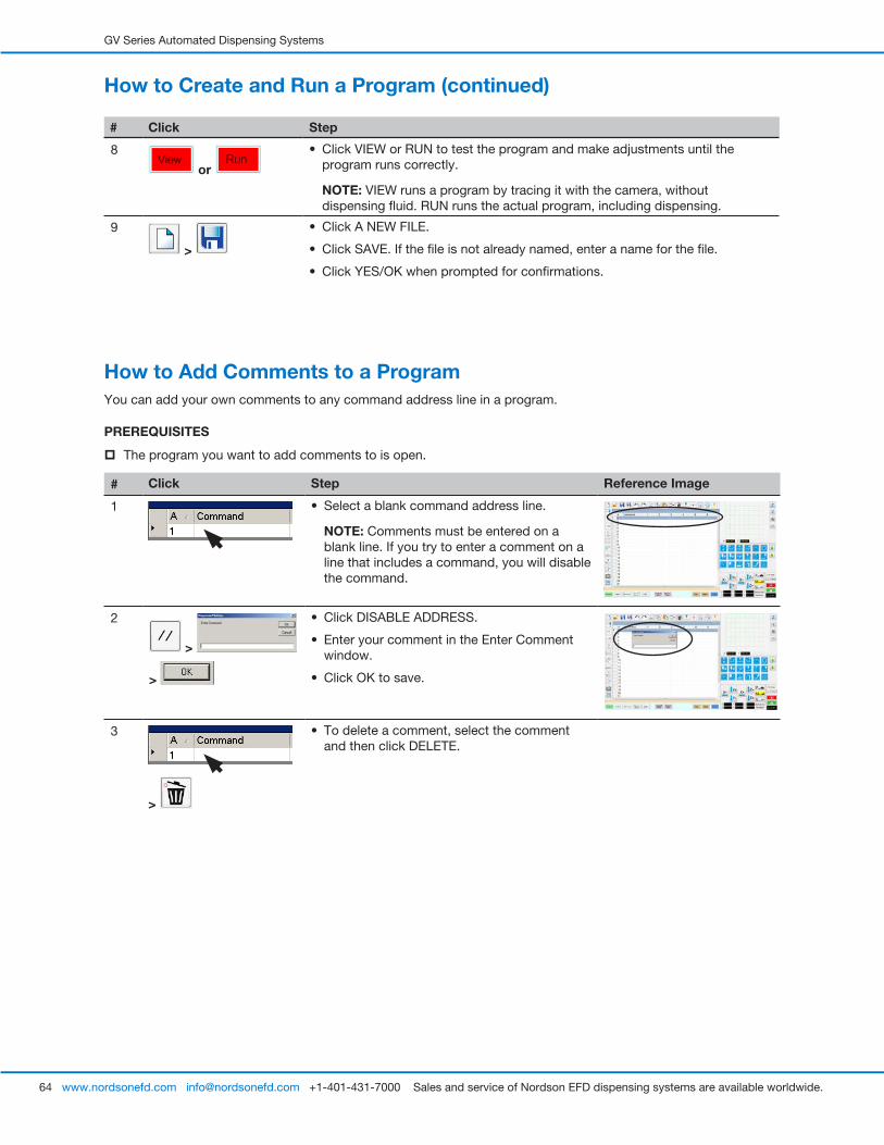
GV Series Automated Dispensing Systems
64 www.nordsonefd.com [email protected] +1-401-431-7000 Sales and service of Nordson EFD dispensing systems are available worldwide.
# Click Step
8
or
• Click VIEW or RUN to test the program and make adjustments until the program runs correctly.
NOTE: VIEW runs a program by tracing it with the camera, without dispensing fluid. RUN runs the actual program, including dispensing.
9
>
• Click A NEW FILE.
• Click SAVE. If the file is not already named, enter a name for the file.
• Click YES/OK when prompted for confirmations.
How to Create and Run a Program (continued)
How to Add Comments to a ProgramYou can add your own comments to any command address line in a program.
PREREQUISITES
� The program you want to add comments to is open.
# Click Step Reference Image
1 • Select a blank command address line.
NOTE: Comments must be entered on a blank line. If you try to enter a comment on a line that includes a command, you will disable the command.
2
>
>
• Click DISABLE ADDRESS.
• Enter your comment in the Enter Comment window.
• Click OK to save.
3
>
• To delete a comment, select the comment and then click DELETE.
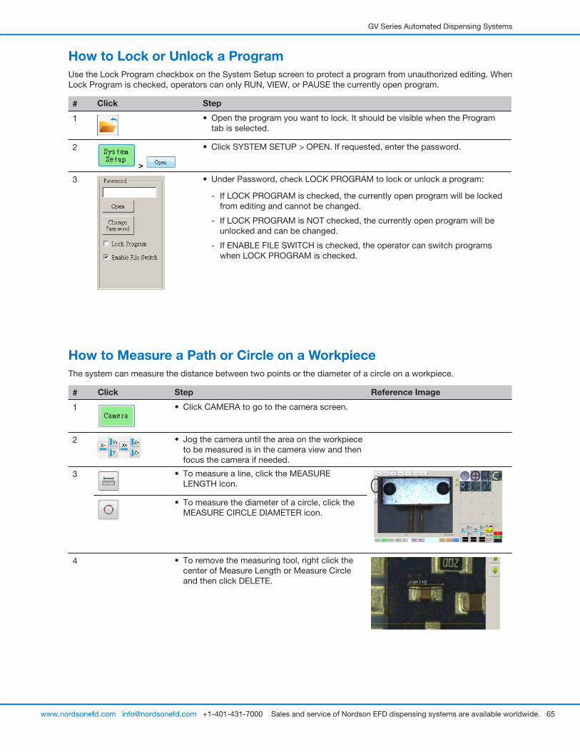
GV Series Automated Dispensing Systems
65www.nordsonefd.com [email protected] +1-401-431-7000 Sales and service of Nordson EFD dispensing systems are available worldwide.
How to Measure a Path or Circle on a WorkpieceThe system can measure the distance between two points or the diameter of a circle on a workpiece.
# Click Step Reference Image
1 • Click CAMERA to go to the camera screen.
2 • Jog the camera until the area on the workpiece to be measured is in the camera view and then focus the camera if needed.
3 • To measure a line, click the MEASURE LENGTH icon.
• To measure the diameter of a circle, click the MEASURE CIRCLE DIAMETER icon.
4 • To remove the measuring tool, right click the center of Measure Length or Measure Circle and then click DELETE.
How to Lock or Unlock a ProgramUse the Lock Program checkbox on the System Setup screen to protect a program from unauthorized editing. When Lock Program is checked, operators can only RUN, VIEW, or PAUSE the currently open program.
# Click Step
1 • Open the program you want to lock. It should be visible when the Program tab is selected.
2
>
• Click SYSTEM SETUP > OPEN. If requested, enter the password.
3 • Under Password, check LOCK PROGRAM to lock or unlock a program:
- If LOCK PROGRAM is checked, the currently open program will be locked from editing and cannot be changed.
- If LOCK PROGRAM is NOT checked, the currently open program will be unlocked and can be changed.
- If ENABLE FILE SWITCH is checked, the operator can switch programs when LOCK PROGRAM is checked.
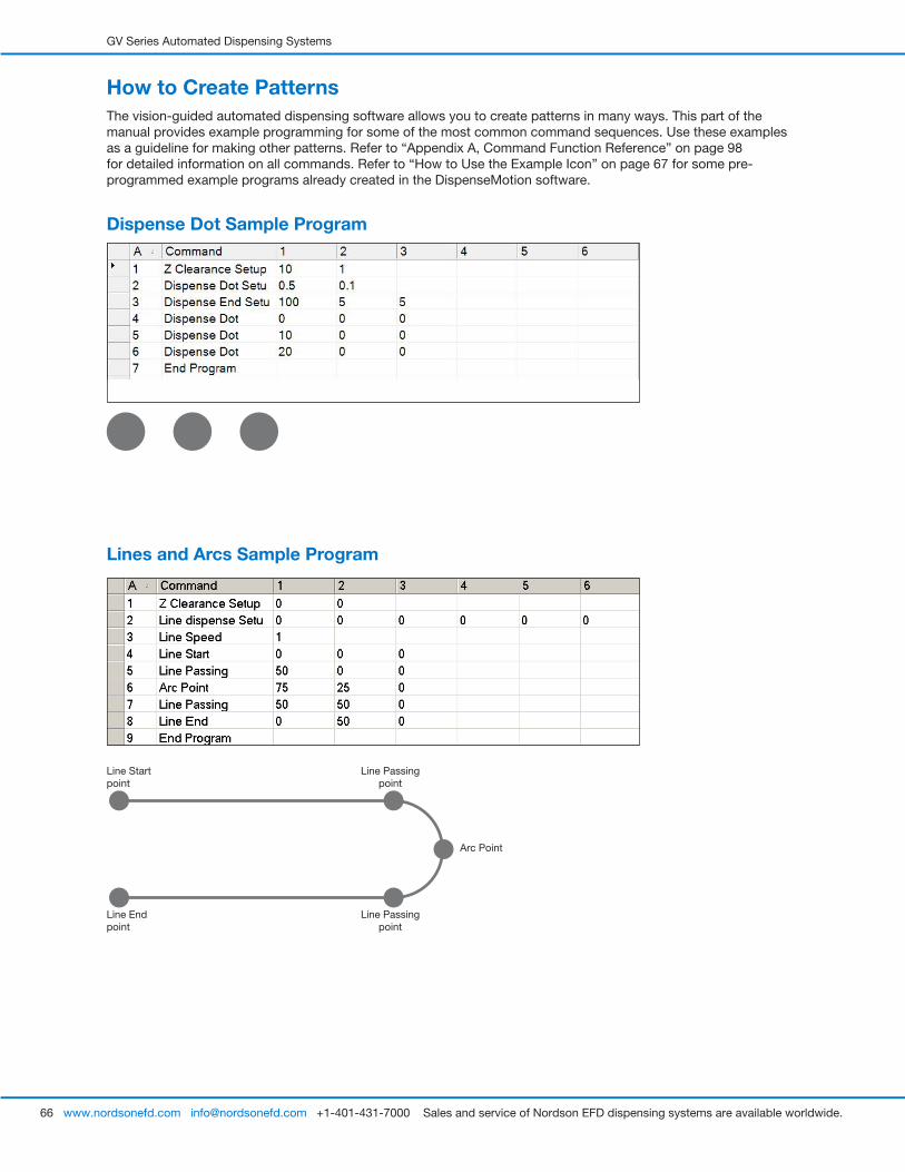
GV Series Automated Dispensing Systems
66 www.nordsonefd.com [email protected] +1-401-431-7000 Sales and service of Nordson EFD dispensing systems are available worldwide.
How to Create PatternsThe vision-guided automated dispensing software allows you to create patterns in many ways. This part of the manual provides example programming for some of the most common command sequences. Use these examples as a guideline for making other patterns. Refer to “Appendix A, Command Function Reference” on page 98 for detailed information on all commands. Refer to “How to Use the Example Icon” on page 67 for some pre-programmed example programs already created in the DispenseMotion software.
Dispense Dot Sample Program
Lines and Arcs Sample Program
Line Start point
Line End point
Arc Point
Line Passing point
Line Passing point
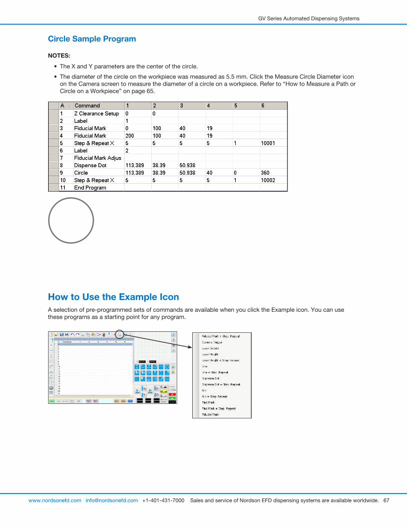
GV Series Automated Dispensing Systems
67www.nordsonefd.com [email protected] +1-401-431-7000 Sales and service of Nordson EFD dispensing systems are available worldwide.
Circle Sample Program
NOTES:
• The X and Y parameters are the center of the circle.
• The diameter of the circle on the workpiece was measured as 5.5 mm. Click the Measure Circle Diameter icon on the Camera screen to measure the diameter of a circle on a workpiece. Refer to “How to Measure a Path or Circle on a Workpiece” on page 65.
How to Use the Example IconA selection of pre-programmed sets of commands are available when you click the Example icon. You can use these programs as a starting point for any program.
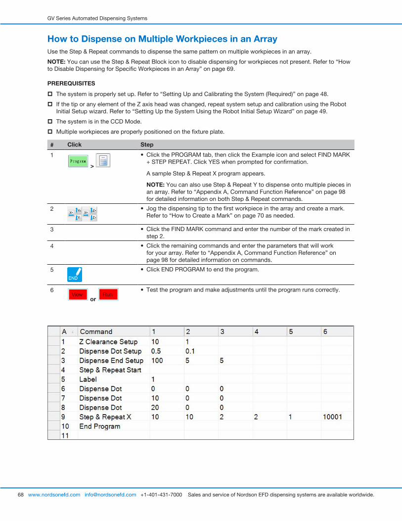
GV Series Automated Dispensing Systems
68 www.nordsonefd.com [email protected] +1-401-431-7000 Sales and service of Nordson EFD dispensing systems are available worldwide.
How to Dispense on Multiple Workpieces in an ArrayUse the Step & Repeat commands to dispense the same pattern on multiple workpieces in an array.
NOTE: You can use the Step & Repeat Block icon to disable dispensing for workpieces not present. Refer to “How to Disable Dispensing for Specific Workpieces in an Array” on page 69.
PREREQUISITES
� The system is properly set up. Refer to “Setting Up and Calibrating the System (Required)” on page 48.
� If the tip or any element of the Z axis head was changed, repeat system setup and calibration using the Robot Initial Setup wizard. Refer to “Setting Up the System Using the Robot Initial Setup Wizard” on page 49.
� The system is in the CCD Mode.
� Multiple workpieces are properly positioned on the fixture plate.
# Click Step
1
>
• Click the PROGRAM tab, then click the Example icon and select FIND MARK + STEP REPEAT. Click YES when prompted for confirmation.
A sample Step & Repeat X program appears.
NOTE: You can also use Step & Repeat Y to dispense onto multiple pieces in an array. Refer to “Appendix A, Command Function Reference” on page 98 for detailed information on both Step & Repeat commands.
2 • Jog the dispensing tip to the first workpiece in the array and create a mark. Refer to “How to Create a Mark” on page 70 as needed.
3 • Click the FIND MARK command and enter the number of the mark created in step 2.
4 • Click the remaining commands and enter the parameters that will work for your array. Refer to “Appendix A, Command Function Reference” on page 98 for detailed information on commands.
5 • Click END PROGRAM to end the program.
6
or
• Test the program and make adjustments until the program runs correctly.
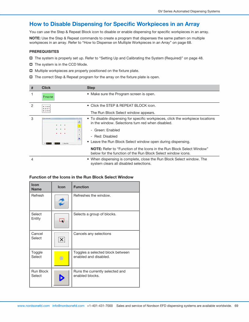
GV Series Automated Dispensing Systems
69www.nordsonefd.com [email protected] +1-401-431-7000 Sales and service of Nordson EFD dispensing systems are available worldwide.
How to Disable Dispensing for Specific Workpieces in an ArrayYou can use the Step & Repeat Block icon to disable or enable dispensing for specific workpieces in an array.
NOTE: Use the Step & Repeat commands to create a program that dispenses the same pattern on multiple workpieces in an array. Refer to “How to Dispense on Multiple Workpieces in an Array” on page 68.
PREREQUISITES
� The system is properly set up. Refer to “Setting Up and Calibrating the System (Required)” on page 48.
� The system is in the CCD Mode.
� Multiple workpieces are properly positioned on the fixture plate.
� The correct Step & Repeat program for the array on the fixture plate is open.
# Click Step
1 • Make sure the Program screen is open.
2 • Click the STEP & REPEAT BLOCK icon.
The Run Block Select window appears.
3 • To disable dispensing for specific workpieces, click the workpiece locations in the window. Selections turn red when disabled.
- Green: Enabled
- Red: Disabled
• Leave the Run Block Select window open during dispensing.
NOTE: Refer to “Function of the Icons in the Run Block Select Window” below for the function of the Run Block Select window icons.
4 • When dispensing is complete, close the Run Block Select window. The system clears all disabled selections.
Function of the Icons in the Run Block Select Window
Icon Name Icon Function
Refresh Refreshes the window.
Select Entity
Selects a group of blocks.
Cancel Select
Cancels any selections
Toggle Select
Toggles a selected block between enabled and disabled.
Run Block Select
Runs the currently selected and enabled blocks.
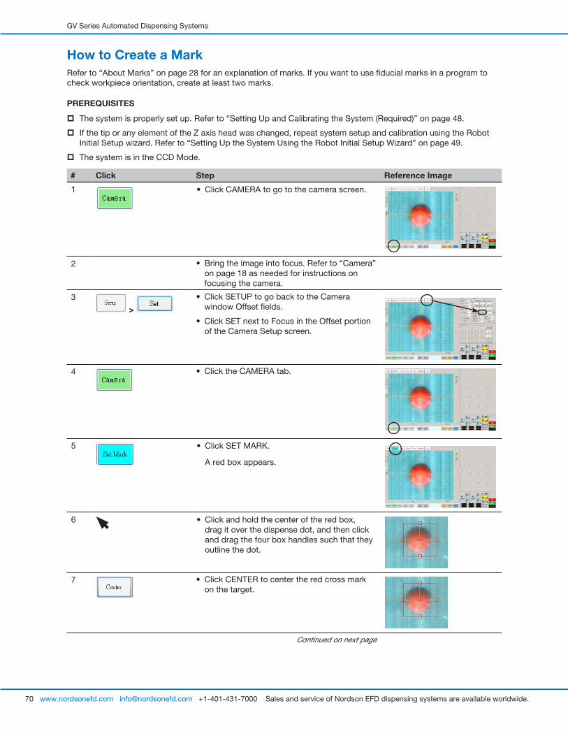
GV Series Automated Dispensing Systems
70 www.nordsonefd.com [email protected] +1-401-431-7000 Sales and service of Nordson EFD dispensing systems are available worldwide.
How to Create a MarkRefer to “About Marks” on page 28 for an explanation of marks. If you want to use fiducial marks in a program to check workpiece orientation, create at least two marks.
PREREQUISITES
� The system is properly set up. Refer to “Setting Up and Calibrating the System (Required)” on page 48.
� If the tip or any element of the Z axis head was changed, repeat system setup and calibration using the Robot Initial Setup wizard. Refer to “Setting Up the System Using the Robot Initial Setup Wizard” on page 49.
� The system is in the CCD Mode.
# Click Step Reference Image
1 • Click CAMERA to go to the camera screen.
2 • Bring the image into focus. Refer to “Camera” on page 18 as needed for instructions on focusing the camera.
3
>
• Click SETUP to go back to the Camera window Offset fields.
• Click SET next to Focus in the Offset portion of the Camera Setup screen.
4 • Click the CAMERA tab.
5 • Click SET MARK.
A red box appears.
6 • Click and hold the center of the red box, drag it over the dispense dot, and then click and drag the four box handles such that they outline the dot.
7 • Click CENTER to center the red cross mark on the target.
Continued on next page
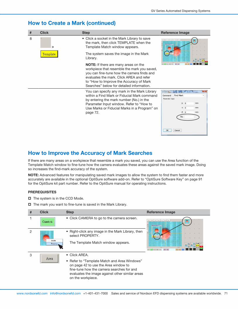
GV Series Automated Dispensing Systems
71www.nordsonefd.com [email protected] +1-401-431-7000 Sales and service of Nordson EFD dispensing systems are available worldwide.
How to Create a Mark (continued)
How to Improve the Accuracy of Mark SearchesIf there are many areas on a workpiece that resemble a mark you saved, you can use the Area function of the Template Match window to fine-tune how the camera evaluates these areas against the saved mark image. Doing so increases the find-mark accuracy of the system.
NOTE: Advanced features for manipulating saved mark images to allow the system to find them faster and more accurately are available in the optional OptiSure software add-on. Refer to “OptiSure Software Key” on page 91 for the OptiSure kit part number. Refer to the OptiSure manual for operating instructions.
PREREQUISITES
� The system is in the CCD Mode.
� The mark you want to fine-tune is saved in the Mark Library.
# Click Step Reference Image
1 • Click CAMERA to go to the camera screen.
2 • Right-click any image in the Mark Library, then select PROPERTY.
The Template Match window appears.
3 • Click AREA.
• Refer to “Template Match and Area Windows” on page 42 to use the Area window to fine-tune how the camera searches for and evaluates the image against other similar areas on the workpiece.
# Click Step Reference Image
8
>
• Click a socket in the Mark Library to save the mark, then click TEMPLATE when the Template Match window appears.
The system saves the image in the Mark Library.
NOTE: If there are many areas on the workpiece that resemble the mark you saved, you can fine-tune how the camera finds and evaluates the mark. Click AREA and refer to “How to Improve the Accuracy of Mark Searches” below for detailed information.
You can specify any mark in the Mark Library within a Find Mark or Fiducial Mark command by entering the mark number (No.) in the Parameter Input window. Refer to “How to Use Marks or Fiducial Marks in a Program” on page 72.
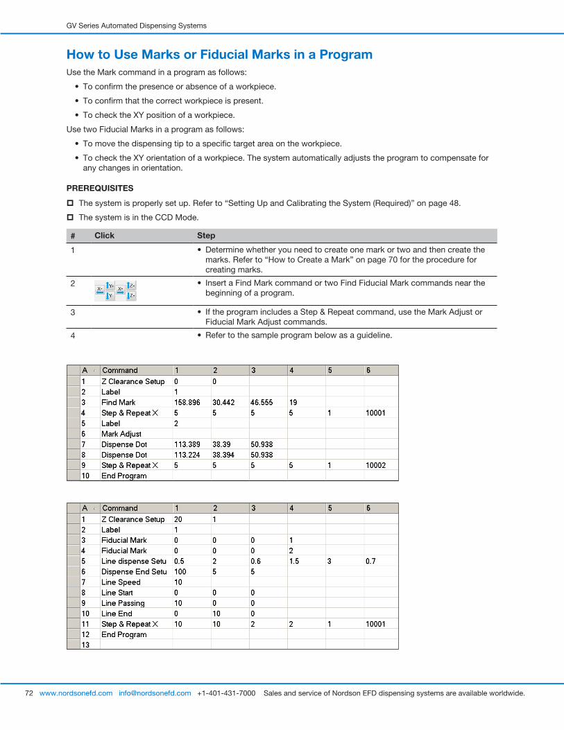
GV Series Automated Dispensing Systems
72 www.nordsonefd.com [email protected] +1-401-431-7000 Sales and service of Nordson EFD dispensing systems are available worldwide.
How to Use Marks or Fiducial Marks in a ProgramUse the Mark command in a program as follows:
• To confirm the presence or absence of a workpiece.
• To confirm that the correct workpiece is present.
• To check the XY position of a workpiece.
Use two Fiducial Marks in a program as follows:
• To move the dispensing tip to a specific target area on the workpiece.
• To check the XY orientation of a workpiece. The system automatically adjusts the program to compensate for any changes in orientation.
PREREQUISITES
� The system is properly set up. Refer to “Setting Up and Calibrating the System (Required)” on page 48.
� The system is in the CCD Mode.
# Click Step
1 • Determine whether you need to create one mark or two and then create the marks. Refer to “How to Create a Mark” on page 70 for the procedure for creating marks.
2 • Insert a Find Mark command or two Find Fiducial Mark commands near the beginning of a program.
3 • If the program includes a Step & Repeat command, use the Mark Adjust or Fiducial Mark Adjust commands.
4 • Refer to the sample program below as a guideline.
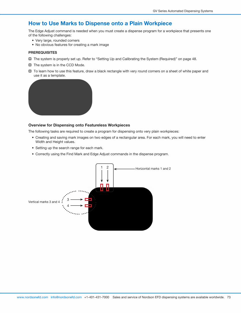
GV Series Automated Dispensing Systems
73www.nordsonefd.com [email protected] +1-401-431-7000 Sales and service of Nordson EFD dispensing systems are available worldwide.
How to Use Marks to Dispense onto a Plain WorkpieceThe Edge Adjust command is needed when you must create a dispense program for a workpiece that presents one of the following challenges:
• Very large, rounded corners• No obvious features for creating a mark image
PREREQUISITES
� The system is properly set up. Refer to “Setting Up and Calibrating the System (Required)” on page 48.
� The system is in the CCD Mode.
� To learn how to use this feature, draw a black rectangle with very round corners on a sheet of white paper and use it as a template.
Overview for Dispensing onto Featureless Workpieces
The following tasks are required to create a program for dispensing onto very plain workpieces:
• Creating and saving mark images on two edges of a rectangular area. For each mark, you will need to enter Width and Height values.
• Setting up the search range for each mark.
• Correctly using the Find Mark and Edge Adjust commands in the dispense program.
Vertical marks 3 and 4
Horizontal marks 1 and 21 2
3
4
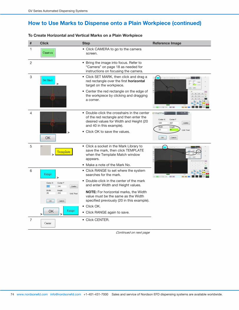
GV Series Automated Dispensing Systems
74 www.nordsonefd.com [email protected] +1-401-431-7000 Sales and service of Nordson EFD dispensing systems are available worldwide.
How to Use Marks to Dispense onto a Plain Workpiece (continued)
To Create Horizontal and Vertical Marks on a Plain Workpiece
# Click Step Reference Image
1 • Click CAMERA to go to the camera screen.
2 • Bring the image into focus. Refer to “Camera” on page 18 as needed for instructions on focusing the camera.
3
>
• Click SET MARK, then click and drag a red rectangle over the first horizontal target on the workpiece.
• Center the red rectangle on the edge of the workpiece by clicking and dragging a corner.
4
>
• Double-click the crosshairs in the center of the red rectangle and then enter the desired values for Width and Height (20 and 40 in this example).
• Click OK to save the values.
5
>
• Click a socket in the Mark Library to save the mark, then click TEMPLATE when the Template Match window appears.
• Make a note of the Mark No.
6
>
> >
• Click RANGE to set where the system searches for the mark.
• Double-click in the center of the mark and enter Width and Height values.
NOTE: For horizontal marks, the Width value must be the same as the Width specified previously (20 in this example).
• Click OK.
• Click RANGE again to save.
7 • Click CENTER.
Continued on next page
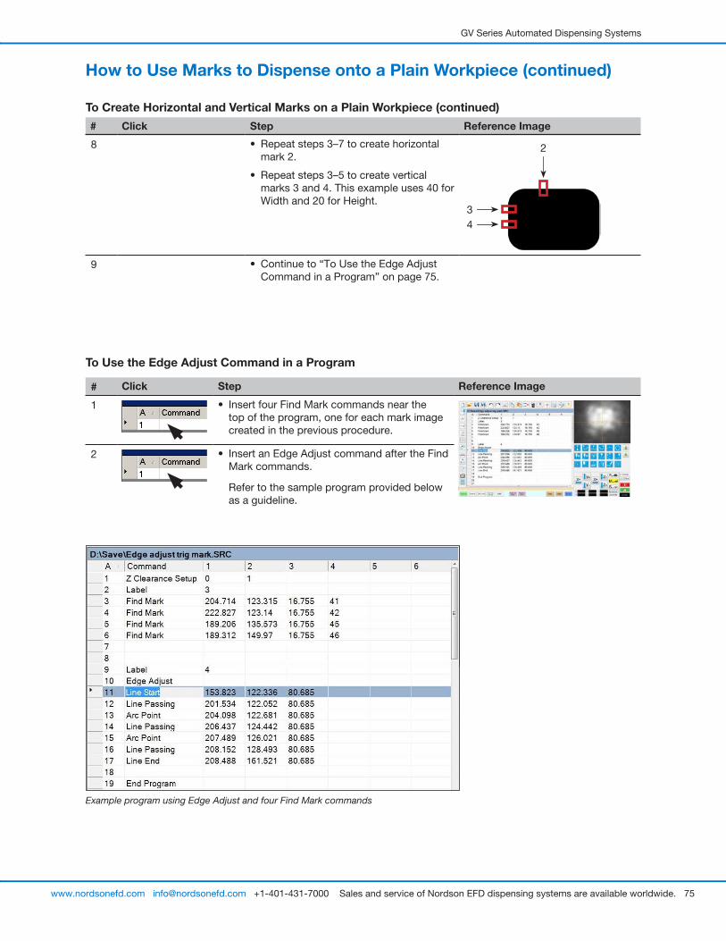
GV Series Automated Dispensing Systems
75www.nordsonefd.com [email protected] +1-401-431-7000 Sales and service of Nordson EFD dispensing systems are available worldwide.
How to Use Marks to Dispense onto a Plain Workpiece (continued)
To Create Horizontal and Vertical Marks on a Plain Workpiece (continued)
Example program using Edge Adjust and four Find Mark commands
To Use the Edge Adjust Command in a Program
# Click Step Reference Image
1 • Insert four Find Mark commands near the top of the program, one for each mark image created in the previous procedure.
2 • Insert an Edge Adjust command after the Find Mark commands.
Refer to the sample program provided below as a guideline.
# Click Step Reference Image
8 • Repeat steps 3–7 to create horizontal mark 2.
• Repeat steps 3–5 to create vertical marks 3 and 4. This example uses 40 for Width and 20 for Height.
34
2
9 • Continue to “To Use the Edge Adjust Command in a Program” on page 75.

GV Series Automated Dispensing Systems
76 www.nordsonefd.com [email protected] +1-401-431-7000 Sales and service of Nordson EFD dispensing systems are available worldwide.
How to Use Mark Follow to Dispense Along a Curved LineThe Mark Follow and Mark Follow Offset commands are needed when you want the system to dispense along a curved line.
PREREQUISITES
� The system is properly set up. Refer to “Setting Up and Calibrating the System (Required)” on page 48.
� The system is in the CCD Mode.
� To learn how to use this feature, draw a thick, slightly curved line on a sheet of white paper and use it as a template.
Overview for Dispensing Along a Curved Line
The following tasks are required to cause the system to properly dispense a long a curved line:
• Creating and saving a mark image of a segment of the line. You will also need to know the length of the line.
• Setting up the search range for the mark images.
• Correctly using the Find Mark, Mark Follow, and Mark Follow Offset commands in a dispense program.
To Create a Mark Image for a Curved Line
# Click Step Reference Image
1 • Click CAMERA to go to the camera screen.
2 • Bring the image into focus. Refer to “Camera” on page 18 as needed for instructions on focusing the camera.
3
>
• Click SET MARK, then click and drag a red rectangle over the first target line segment on the workpiece.
NOTE: For this example, the mark is created about 2–3 mm (0.8–0.12") from the left side of line, to allow the system to find the mark within the specified range limits when the workpiece is changed.
4
>
• Double-click the crosshairs in the center of the red rectangle and then enter the desired values for Width and Height (20 and 60 in this example).
• Click OK to save the values.
Continued on next page
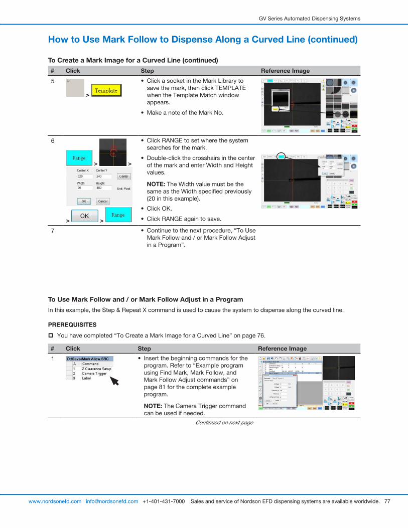
GV Series Automated Dispensing Systems
77www.nordsonefd.com [email protected] +1-401-431-7000 Sales and service of Nordson EFD dispensing systems are available worldwide.
# Click Step Reference Image
5
>
• Click a socket in the Mark Library to save the mark, then click TEMPLATE when the Template Match window appears.
• Make a note of the Mark No.
6
> >
> >
• Click RANGE to set where the system searches for the mark.
• Double-click the crosshairs in the center of the mark and enter Width and Height values.
NOTE: The Width value must be the same as the Width specified previously (20 in this example).
• Click OK.
• Click RANGE again to save.
7 • Continue to the next procedure, “To Use Mark Follow and / or Mark Follow Adjust in a Program”.
To Use Mark Follow and / or Mark Follow Adjust in a Program
In this example, the Step & Repeat X command is used to cause the system to dispense along the curved line.
PREREQUISITES
� You have completed “To Create a Mark Image for a Curved Line” on page 76.
# Click Step Reference Image
1 • Insert the beginning commands for the program. Refer to “Example program using Find Mark, Mark Follow, and Mark Follow Adjust commands” on page 81 for the complete example program.
NOTE: The Camera Trigger command can be used if needed.
Continued on next page
How to Use Mark Follow to Dispense Along a Curved Line (continued)
To Create a Mark Image for a Curved Line (continued)
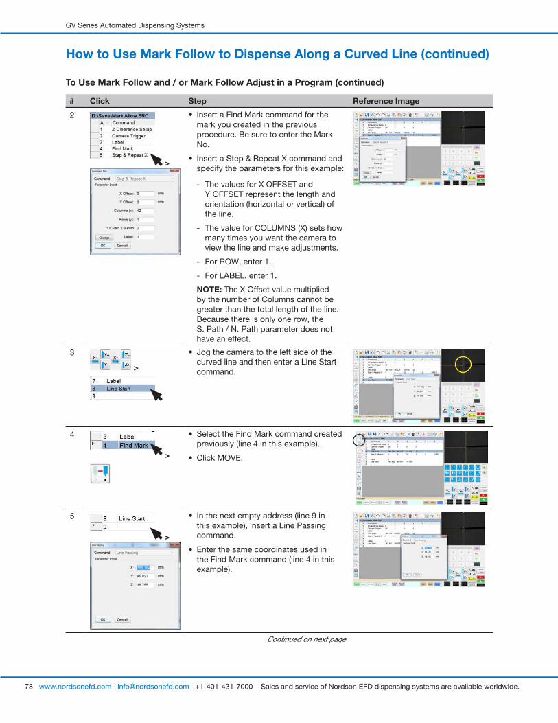
GV Series Automated Dispensing Systems
78 www.nordsonefd.com [email protected] +1-401-431-7000 Sales and service of Nordson EFD dispensing systems are available worldwide.
How to Use Mark Follow to Dispense Along a Curved Line (continued)
To Use Mark Follow and / or Mark Follow Adjust in a Program (continued)
# Click Step Reference Image
2
>
• Insert a Find Mark command for the mark you created in the previous procedure. Be sure to enter the Mark No.
• Insert a Step & Repeat X command and specify the parameters for this example:
- The values for X OFFSET and Y OFFSET represent the length and orientation (horizontal or vertical) of the line.
- The value for COLUMNS (X) sets how many times you want the camera to view the line and make adjustments.
- For ROW, enter 1.
- For LABEL, enter 1.
NOTE: The X Offset value multiplied by the number of Columns cannot be greater than the total length of the line. Because there is only one row, the S. Path / N. Path parameter does not have an effect.
3
>
• Jog the camera to the left side of the curved line and then enter a Line Start command.
4
>
• Select the Find Mark command created previously (line 4 in this example).
• Click MOVE.
5
>
• In the next empty address (line 9 in this example), insert a Line Passing command.
• Enter the same coordinates used in the Find Mark command (line 4 in this example).
Continued on next page

GV Series Automated Dispensing Systems
79www.nordsonefd.com [email protected] +1-401-431-7000 Sales and service of Nordson EFD dispensing systems are available worldwide.
How to Use Mark Follow to Dispense Along a Curved Line (continued)
To Use Mark Follow and / or Mark Follow Adjust in a Program (continued)
# Click Step Reference Image
6
>
• In the next empty address (line 10 in this example), insert a second Step & Repeat X command.
NOTE: This Step & Repeat command is the same as the previous Step & Repeat command (Line 5 in this example), except for the Label.
• Change the last parameter from Label to Address and enter the address of the first Line Passing command (line 9 in this example).
7 • Click EXTEND STEP & REPEAT.
The system extends the Step & Repeat X command by adding Line Passing commands for many line passing points along the line.
8 • Insert a blank address after the Line Start command (line 8 in this example).
9
>
• In the blank address, insert a MARK FOLLOW command.
• Enter 1 to set the command to ON.
10
>
• After the last Line Passing command (line 51 in this example), insert another MARK FOLLOW command.
• Enter 0 to set the command to OFF.
Continued on next page

GV Series Automated Dispensing Systems
80 www.nordsonefd.com [email protected] +1-401-431-7000 Sales and service of Nordson EFD dispensing systems are available worldwide.
# Click Step Reference Image
11
>
• Jog the camera to the right side of the curved line and then insert a LINE END command.
• Insert an END PROGRAM command.
12
>
• Return to PROGRAM screen and then click RUN to test the program.
The system should go to the Find Mark image created for this program, then perform the Step & Repeat X command in the X direction 42 times, at an interval of 3 mm each time. Each Step & Repeat X command aligns itself with the center of the line. Once done, the system dispenses along the line, following the curve.
NOTES:
- Click VIEW if you want to view the pattern before running it.
- Because the line for this example is fairly straight, this program works at this point using only a Mark Follow command. For deeper curves, the Mark Follow Offset command is needed. Continue to the next step for an explanation of how to use the Mark Follow Offset command for deeper curves.
13
>
If needed for a line with a deeper curve:
• Insert a MARK FOLLOW OFFSET command and enter X or Y offset values to be applied to all commands below it.
• Insert additional MARK FOLLOW OFFSET commands as needed to obtain the desired dispense result.
NOTES:
- To remove the effect of a Mark Follow Offset command, enter another Mark Follow Offset command with the X and Y values set to 0.
- If you are testing this example using a slight curve, you might need to recreate it using a deeper curve.
How to Use Mark Follow to Dispense Along a Curved Line (continued)
To Use Mark Follow and / or Mark Follow Adjust in a Program (continued)
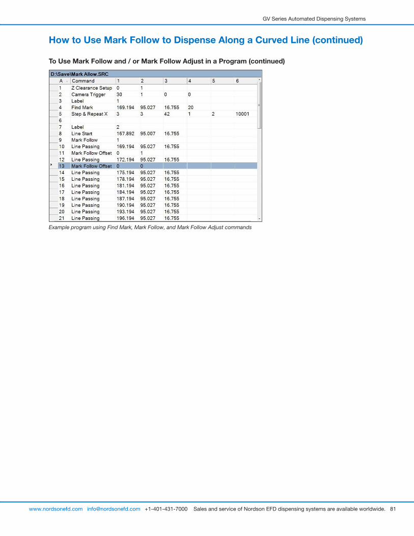
GV Series Automated Dispensing Systems
81www.nordsonefd.com [email protected] +1-401-431-7000 Sales and service of Nordson EFD dispensing systems are available worldwide.
Example program using Find Mark, Mark Follow, and Mark Follow Adjust commands
How to Use Mark Follow to Dispense Along a Curved Line (continued)
To Use Mark Follow and / or Mark Follow Adjust in a Program (continued)
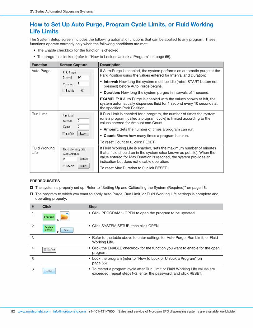
GV Series Automated Dispensing Systems
82 www.nordsonefd.com [email protected] +1-401-431-7000 Sales and service of Nordson EFD dispensing systems are available worldwide.
How to Set Up Auto Purge, Program Cycle Limits, or Fluid Working Life LimitsThe System Setup screen includes the following automatic functions that can be applied to any program. These functions operate correctly only when the following conditions are met:
• The Enable checkbox for the function is checked.
• The program is locked (refer to “How to Lock or Unlock a Program” on page 65).
Function Screen Capture Description
Auto Purge If Auto Purge is enabled, the system performs an automatic purge at the Park Position using the values entered for Interval and Duration:
• Interval: How long the system must be idle (robot START button not pressed) before Auto Purge begins.
• Duration: How long the system purges in intervals of 1 second.
EXAMPLE: If Auto Purge is enabled with the values shown at left, the system automatically dispenses fluid for 1 second every 10 seconds at the specified Park Position.
Run Limit If Run Limit is enabled for a program, the number of times the system runs a program (called a program cycle) is limited according to the values entered for Amount and Count:
• Amount: Sets the number of times a program can run.
• Count: Shows how many times a program has run.
To reset Count to 0, click RESET.
Fluid Working Life
If Fluid Working Life is enabled, sets the maximum number of minutes that a fluid should be in the system (also known as pot life). When the value entered for Max Duration is reached, the system provides an indication but does not disable operation.
To reset Max Duration to 0, click RESET.
PREREQUISITES
� The system is properly set up. Refer to “Setting Up and Calibrating the System (Required)” on page 48.
� The program to which you want to apply Auto Purge, Run Limit, or Fluid Working Life settings is complete and operating properly.
# Click Step
1
>
• Click PROGRAM > OPEN to open the program to be updated.
2
>
• Click SYSTEM SETUP, then click OPEN.
3 • Refer to the table above to enter settings for Auto Purge, Run Limit, or Fluid Working Life.
4 • Click the ENABLE checkbox for the function you want to enable for the open program.
5 • Lock the program (refer to “How to Lock or Unlock a Program” on page 65).
6 • To restart a program cycle after Run Limit or Fluid Working Life values are exceeded, repeat steps1–2, enter the password, and click RESET.
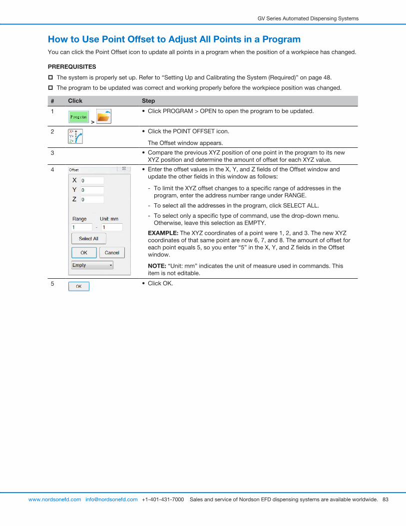
GV Series Automated Dispensing Systems
83www.nordsonefd.com [email protected] +1-401-431-7000 Sales and service of Nordson EFD dispensing systems are available worldwide.
How to Use Point Offset to Adjust All Points in a ProgramYou can click the Point Offset icon to update all points in a program when the position of a workpiece has changed.
PREREQUISITES
� The system is properly set up. Refer to “Setting Up and Calibrating the System (Required)” on page 48.
� The program to be updated was correct and working properly before the workpiece position was changed.
# Click Step
1
>
• Click PROGRAM > OPEN to open the program to be updated.
2 • Click the POINT OFFSET icon.
The Offset window appears.
3 • Compare the previous XYZ position of one point in the program to its new XYZ position and determine the amount of offset for each XYZ value.
4 • Enter the offset values in the X, Y, and Z fields of the Offset window and update the other fields in this window as follows:
- To limit the XYZ offset changes to a specific range of addresses in the program, enter the address number range under RANGE.
- To select all the addresses in the program, click SELECT ALL.
- To select only a specific type of command, use the drop-down menu. Otherwise, leave this selection as EMPTY.
EXAMPLE: The XYZ coordinates of a point were 1, 2, and 3. The new XYZ coordinates of that same point are now 6, 7, and 8. The amount of offset for each point equals 5, so you enter “5” in the X, Y, and Z fields in the Offset window.
NOTE: “Unit: mm” indicates the unit of measure used in commands. This item is not editable.
5 • Click OK.
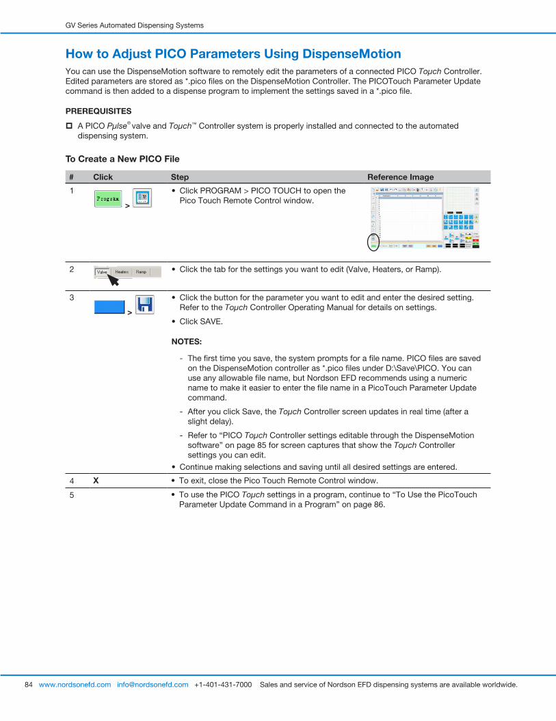
GV Series Automated Dispensing Systems
84 www.nordsonefd.com [email protected] +1-401-431-7000 Sales and service of Nordson EFD dispensing systems are available worldwide.
How to Adjust PICO Parameters Using DispenseMotionYou can use the DispenseMotion software to remotely edit the parameters of a connected PICO Toµch Controller. Edited parameters are stored as *.pico files on the DispenseMotion Controller. The PICOTouch Parameter Update command is then added to a dispense program to implement the settings saved in a *.pico file.
PREREQUISITES
� A PICO Pµlse® valve and Toµch™ Controller system is properly installed and connected to the automated dispensing system.
To Create a New PICO File
# Click Step Reference Image
1
>
• Click PROGRAM > PICO TOUCH to open the Pico Touch Remote Control window.
2 • Click the tab for the settings you want to edit (Valve, Heaters, or Ramp).
3
>
• Click the button for the parameter you want to edit and enter the desired setting. Refer to the Toµch Controller Operating Manual for details on settings.
• Click SAVE.
NOTES:
- The first time you save, the system prompts for a file name. PICO files are saved on the DispenseMotion controller as *.pico files under D:\Save\PICO. You can use any allowable file name, but Nordson EFD recommends using a numeric name to make it easier to enter the file name in a PicoTouch Parameter Update command.
- After you click Save, the Toµch Controller screen updates in real time (after a slight delay).
- Refer to “PICO Toµch Controller settings editable through the DispenseMotion software” on page 85 for screen captures that show the Toµch Controller settings you can edit.
• Continue making selections and saving until all desired settings are entered.
4 X • To exit, close the Pico Touch Remote Control window.
5 • To use the PICO Toµch settings in a program, continue to “To Use the PicoTouch Parameter Update Command in a Program” on page 86.
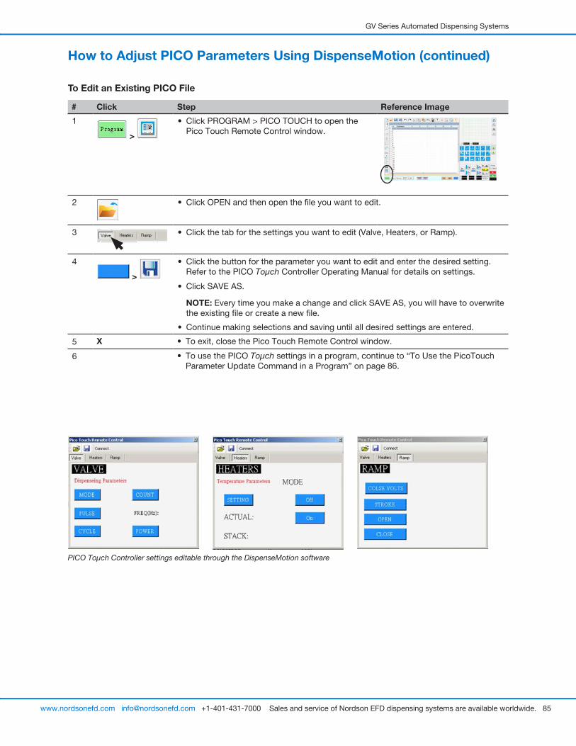
GV Series Automated Dispensing Systems
85www.nordsonefd.com [email protected] +1-401-431-7000 Sales and service of Nordson EFD dispensing systems are available worldwide.
PICO Toµch Controller settings editable through the DispenseMotion software
To Edit an Existing PICO File
# Click Step Reference Image
1
>
• Click PROGRAM > PICO TOUCH to open the Pico Touch Remote Control window.
2 • Click OPEN and then open the file you want to edit.
3 • Click the tab for the settings you want to edit (Valve, Heaters, or Ramp).
4
>
• Click the button for the parameter you want to edit and enter the desired setting. Refer to the PICO Toµch Controller Operating Manual for details on settings.
• Click SAVE AS.
NOTE: Every time you make a change and click SAVE AS, you will have to overwrite the existing file or create a new file.
• Continue making selections and saving until all desired settings are entered.
5 X • To exit, close the Pico Touch Remote Control window.
6 • To use the PICO Toµch settings in a program, continue to “To Use the PicoTouch Parameter Update Command in a Program” on page 86.
How to Adjust PICO Parameters Using DispenseMotion (continued)
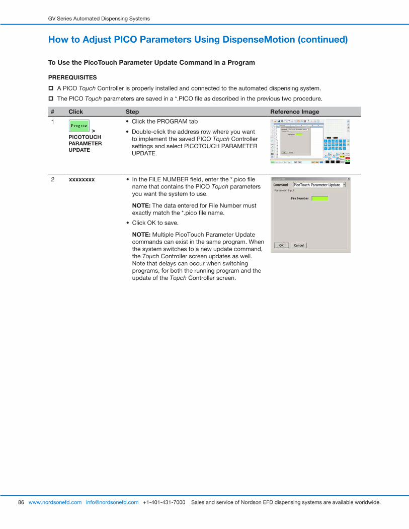
GV Series Automated Dispensing Systems
86 www.nordsonefd.com [email protected] +1-401-431-7000 Sales and service of Nordson EFD dispensing systems are available worldwide.
To Use the PicoTouch Parameter Update Command in a Program
PREREQUISITES
� A PICO Toµch Controller is properly installed and connected to the automated dispensing system.
� The PICO Toµch parameters are saved in a *.PICO file as described in the previous two procedure.
# Click Step Reference Image
1
> PICOTOUCH PARAMETER UPDATE
• Click the PROGRAM tab
• Double-click the address row where you want to implement the saved PICO Toµch Controller settings and select PICOTOUCH PARAMETER UPDATE.
2 xxxxxxxx • In the FILE NUMBER field, enter the *.pico file name that contains the PICO Toµch parameters you want the system to use.
NOTE: The data entered for File Number must exactly match the *.pico file name.
• Click OK to save.
NOTE: Multiple PicoTouch Parameter Update commands can exist in the same program. When the system switches to a new update command, the Toµch Controller screen updates as well. Note that delays can occur when switching programs, for both the running program and the update of the Toµch Controller screen.
How to Adjust PICO Parameters Using DispenseMotion (continued)
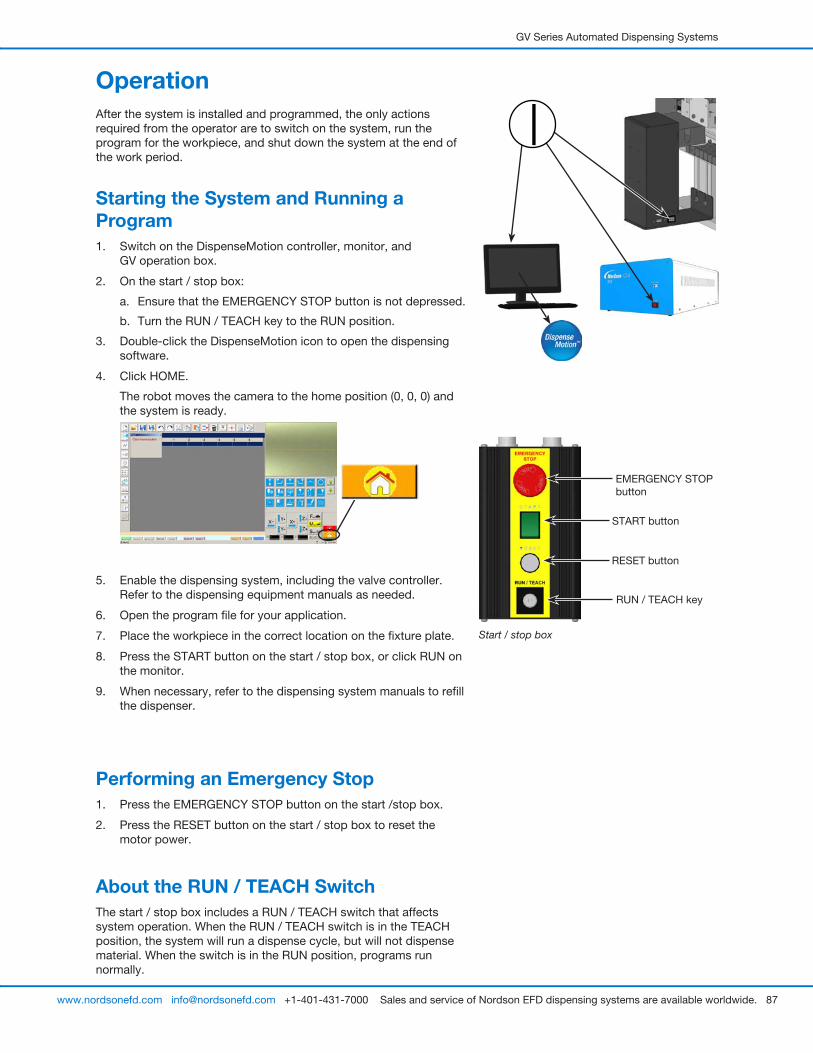
GV Series Automated Dispensing Systems
87www.nordsonefd.com [email protected] +1-401-431-7000 Sales and service of Nordson EFD dispensing systems are available worldwide.
OperationAfter the system is installed and programmed, the only actions required from the operator are to switch on the system, run the program for the workpiece, and shut down the system at the end of the work period.
Starting the System and Running a Program1. Switch on the DispenseMotion controller, monitor, and
GV operation box.
2. On the start / stop box:
a. Ensure that the EMERGENCY STOP button is not depressed.
b. Turn the RUN / TEACH key to the RUN position.
3. Double-click the DispenseMotion icon to open the dispensing software.
4. Click HOME.
The robot moves the camera to the home position (0, 0, 0) and the system is ready.
5. Enable the dispensing system, including the valve controller. Refer to the dispensing equipment manuals as needed.
6. Open the program file for your application.
7. Place the workpiece in the correct location on the fixture plate.
8. Press the START button on the start / stop box, or click RUN on the monitor.
9. When necessary, refer to the dispensing system manuals to refill the dispenser.
Performing an Emergency Stop1. Press the EMERGENCY STOP button on the start /stop box.
2. Press the RESET button on the start / stop box to reset the motor power.
About the RUN / TEACH SwitchThe start / stop box includes a RUN / TEACH switch that affects system operation. When the RUN / TEACH switch is in the TEACH position, the system will run a dispense cycle, but will not dispense material. When the switch is in the RUN position, programs run normally.
Start / stop box
EMERGENCY STOP button
START button
RESET button
RUN / TEACH key
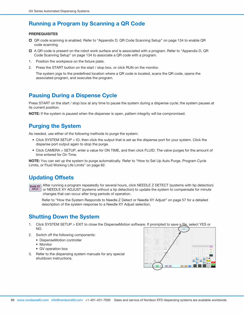
GV Series Automated Dispensing Systems
88 www.nordsonefd.com [email protected] +1-401-431-7000 Sales and service of Nordson EFD dispensing systems are available worldwide.
Running a Program by Scanning a QR Code
PREREQUISITES
� QR code scanning is enabled. Refer to “Appendix D, QR Code Scanning Setup” on page 134 to enable QR code scanning.
� A QR code is present on the robot work surface and is associated with a program. Refer to “Appendix D, QR Code Scanning Setup” on page 134 to associate a QR code with a program.
1. Position the workpiece on the fixture plate.
2. Press the START button on the start / stop box, or click RUN on the monitor.
The system jogs to the predefined location where a QR code is located, scans the QR code, opens the associated program, and executes the program.
Pausing During a Dispense CyclePress START on the start / stop box at any time to pause the system during a dispense cycle; the system pauses at its current position.
NOTE: If the system is paused when the dispenser is open, pattern integrity will be compromised.
Purging the SystemAs needed, use either of the following methods to purge the system:
• Click SYSTEM SETUP > IO, then click the output that is set as the dispense port for your system. Click the dispense port output again to stop the purge.
• Click CAMERA > SETUP, enter a value for ON TIME, and then click FLUID. The valve purges for the amount of time entered for On Time.
NOTE: You can set up the system to purge automatically. Refer to “How to Set Up Auto Purge, Program Cycle Limits, or Fluid Working Life Limits” on page 82.
Updating Offsets After running a program repeatedly for several hours, click NEEDLE Z DETECT (systems with tip detection) or NEEDLE XY ADJUST (systems without a tip detection) to update the system to compensate for minute changes that can occur after long periods of operation.
Refer to “How the System Responds to Needle Z Detect or Needle XY Adjust” on page 57 for a detailed description of the system response to a Needle XY Adjust selection.
Shutting Down the System1. Click SYSTEM SETUP > EXIT to close the DispenseMotion software. If prompted to save a file, select YES or
NO.
2. Switch off the following components:
• DispenseMotion controller• Monitor• GV operation box
3. Refer to the dispensing system manuals for any special shutdown instructions.
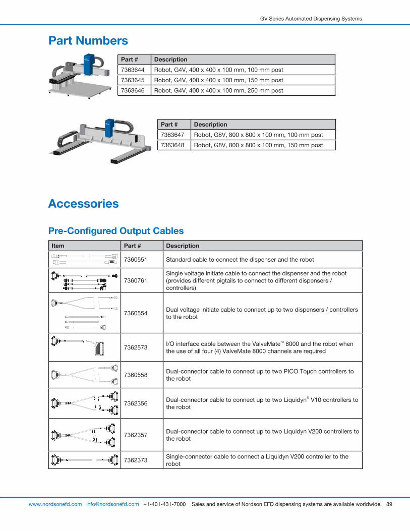
GV Series Automated Dispensing Systems
89www.nordsonefd.com [email protected] +1-401-431-7000 Sales and service of Nordson EFD dispensing systems are available worldwide.
Accessories
Pre-Configured Output CablesItem Part # Description
7360551 Standard cable to connect the dispenser and the robot
7360761Single voltage initiate cable to connect the dispenser and the robot (provides different pigtails to connect to different dispensers / controllers)
7360554Dual voltage initiate cable to connect up to two dispensers / controllers to the robot
:
7362573I/O interface cable between the ValveMate™ 8000 and the robot when the use of all four (4) ValveMate 8000 channels are required
7360558Dual-connector cable to connect up to two PICO Toµch controllers to the robot
7362356Dual-connector cable to connect up to two Liquidyn® V10 controllers to the robot
7362357Dual-connector cable to connect up to two Liquidyn V200 controllers to the robot
7362373Single-connector cable to connect a Liquidyn V200 controller to the robot
Part NumbersPart # Description
7363644 Robot, G4V, 400 x 400 x 100 mm, 100 mm post
7363645 Robot, G4V, 400 x 400 x 100 mm, 150 mm post
7363646 Robot, G4V, 400 x 400 x 100 mm, 250 mm post
Part # Description
7363647 Robot, G8V, 800 x 800 x 100 mm, 100 mm post
7363648 Robot, G8V, 800 x 800 x 100 mm, 150 mm post

GV Series Automated Dispensing Systems
90 www.nordsonefd.com [email protected] +1-401-431-7000 Sales and service of Nordson EFD dispensing systems are available worldwide.
Accessories (continued)
Start / Stop BoxThe start / stop box accessory facilitates input / output connections for remote functions, such as an start or emergency stop button. Refer to “Example Input / Output Connections” on page 97 for schematics.
Item Part # Description
7360865 Start / stop accessory box, European Community
Tip DetectorThe optional tip detector allows you to automatically update both the XY offsets and the Z height by clicking on Needle Z Detect. The Needle Z Detect button is present only on systems that include the tip detector. Refer to “(Only GV Systems With a Tip Detector) Setting Up the Tip Detector” on page 125 to set up the tip detector.
Item Part # Description
7363925 Tip detector accessory kit, G4V
7363976 Tip detector accessory kit, G8V
Height SensorThe optional height sensor can detect any variation from the original Z height program values from workpiece to workpiece. If the Z height changes, the system detects the new Z height values and adjusts the program accordingly. Refer to “Appendix F, Height Sensor Setup and Use” on page 142 for details.
Item Part # Description
7361667 Height sensor accessory kit, E / EV Series
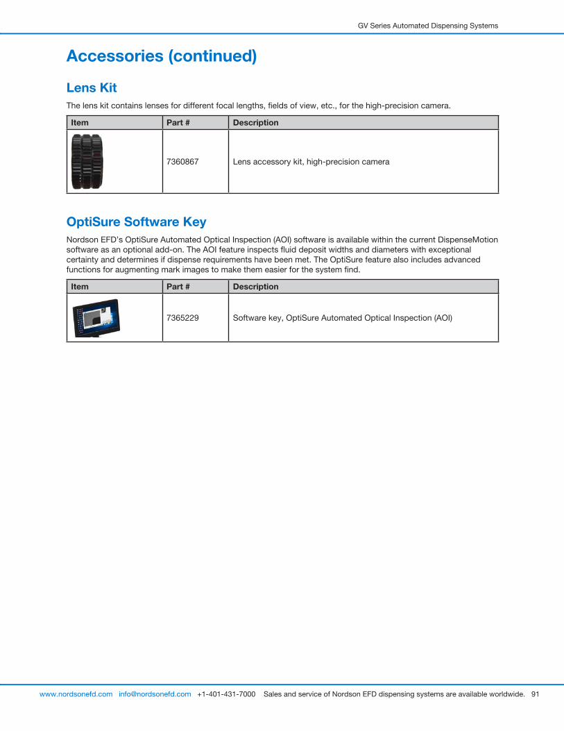
GV Series Automated Dispensing Systems
91www.nordsonefd.com [email protected] +1-401-431-7000 Sales and service of Nordson EFD dispensing systems are available worldwide.
Lens KitThe lens kit contains lenses for different focal lengths, fields of view, etc., for the high-precision camera.
Item Part # Description
7360867 Lens accessory kit, high-precision camera
OptiSure Software KeyNordson EFD’s OptiSure Automated Optical Inspection (AOI) software is available within the current DispenseMotion software as an optional add-on. The AOI feature inspects fluid deposit widths and diameters with exceptional certainty and determines if dispense requirements have been met. The OptiSure feature also includes advanced functions for augmenting mark images to make them easier for the system find.
Item Part # Description
7365229 Software key, OptiSure Automated Optical Inspection (AOI)
Accessories (continued)
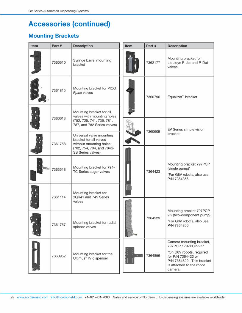
GV Series Automated Dispensing Systems
92 www.nordsonefd.com [email protected] +1-401-431-7000 Sales and service of Nordson EFD dispensing systems are available worldwide.
Accessories (continued)
Item Part # Description
7360610Syringe barrel mounting bracket
7361815Mounting bracket for PICO Pµlse valves
7360613
Mounting bracket for all valves with mounting holes (752, 725, 741, 736, 781, 787, and 782 Series valves)
7361758
Universal valve mounting bracket for all valves without mounting holes (702, 754, 794, and 784S-SS Series valves)
7363518Mounting bracket for 794-TC Series auger valves
7361114Mounting bracket for xQR41 and 745 Series valves
7361757Mounting bracket for radial spinner valves
7360952Mounting bracket for the Ultimus™ IV dispenser
Mounting Brackets
Item Part # Description
7362177Mounting bracket for Liquidyn P-Jet and P-Dot valves
7360796 Equalizer™ bracket
7360609EV Series simple vision bracket
7364423
Mounting bracket 797PCP (single pump)*
*For G8V robots, also use P/N 7364856
7364529
Mounting bracket 797PCP-2K (two-component pump)*
*For G8V robots, also use P/N 7364856
7364856
Camera mounting bracket, 797PCP / 797PCP-2K*
*On G8V robots, required for P/N 7364423 or P/N 7364529 . This bracket is attached to the robot camera.
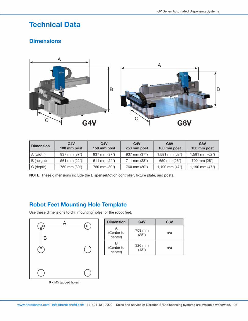
GV Series Automated Dispensing Systems
93www.nordsonefd.com [email protected] +1-401-431-7000 Sales and service of Nordson EFD dispensing systems are available worldwide.
Technical Data
Dimensions
Dimension G4V 100 mm post
G4V 150 mm post
G4V 250 mm post
G8V 100 mm post
G8V 150 mm post
A (width) 937 mm (37") 937 mm (37") 937 mm (37") 1,581 mm (62") 1,581 mm (62")
B (height) 561 mm (22") 611 mm (24") 711 mm (28") 650 mm (26") 700 mm (28")
C (depth) 760 mm (30") 760 mm (30") 760 mm (30") 1,190 mm (47") 1,190 mm (47")
NOTE: These dimensions include the DispenseMotion controller, fixture plate, and posts.
Robot Feet Mounting Hole TemplateUse these dimensions to drill mounting holes for the robot feet.
6 x M5 tapped holes
Dimension G4V G8V
A(Center to
center)
709 mm (28")
n/a
B(Center to
center)
326 mm (13")
n/a
G4V
A
G8V
B
C
B
A
B
C
A
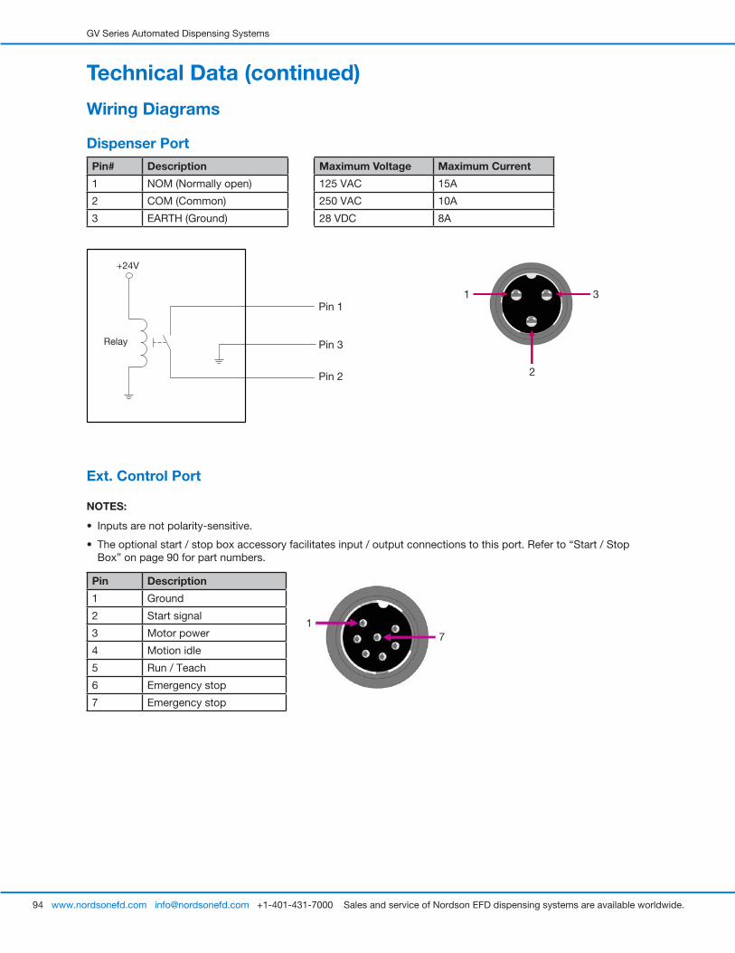
GV Series Automated Dispensing Systems
94 www.nordsonefd.com [email protected] +1-401-431-7000 Sales and service of Nordson EFD dispensing systems are available worldwide.
2
1 3
17
Maximum Voltage Maximum Current
125 VAC 15A
250 VAC 10A
28 VDC 8A
Pin# Description
1 NOM (Normally open)
2 COM (Common)
3 EARTH (Ground)
Pin 1
Pin 2
Pin 3
+24V
Relay
Ext. Control Port
NOTES:
• Inputs are not polarity-sensitive.
• The optional start / stop box accessory facilitates input / output connections to this port. Refer to “Start / Stop Box” on page 90 for part numbers.
Pin Description
1 Ground
2 Start signal
3 Motor power
4 Motion idle
5 Run / Teach
6 Emergency stop
7 Emergency stop
Technical Data (continued)
Wiring Diagrams
Dispenser Port

GV Series Automated Dispensing Systems
95www.nordsonefd.com [email protected] +1-401-431-7000 Sales and service of Nordson EFD dispensing systems are available worldwide.
I/O Port
NOTES:
• Outputs are rated at 125 mA.
• Courtesy +24 VDC output is rated at 3.0 Amp.
Pin Description Pin Description Pin Description
1 Input 1 10 Not connected 19 Output 6
2 Input 2 11 GND 20 Output 7
3 Input 3 12 GND 21 Output 8
4 Input 4 13 GND 22 Not connected
5 Input 5 14 Output 1 23 Not connected
6 Input 6 15 Output 2 24 +24 VDC
7 Input 7 16 Output 3 25 +24 VDC
8 Input 8 17 Output 4
9 Not connected 18 Output 5
Technical Data (continued)
Input schematic Output schematic
Pin 25
Input X
+24V
Output X
Pin 13
+24V
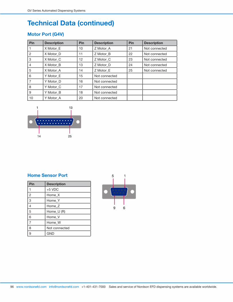
GV Series Automated Dispensing Systems
96 www.nordsonefd.com [email protected] +1-401-431-7000 Sales and service of Nordson EFD dispensing systems are available worldwide.
Home Sensor Port
Pin Description
1 +5 VDC
2 Home_X
3 Home_Y
4 Home_Z
5 Home_U (R)
6 Home_V
7 Home_W
8 Not connected
9 GND
Technical Data (continued)
Motor Port (G4V)
Pin Description Pin Description Pin Description
1 X Motor_E 10 Z Motor_A 21 Not connected
2 X Motor_D 11 Z Motor_B 22 Not connected
3 X Motor_C 12 Z Motor_C 23 Not connected
4 X Motor_B 13 Z Motor_D 24 Not connected
5 X Motor_A 14 Z Motor_E 25 Not connected
6 Y Motor_E 15 Not connected
7 Y Motor_D 16 Not connected
8 Y Motor_C 17 Not connected
9 Y Motor_B 18 Not connected
10 Y Motor_A 20 Not connected
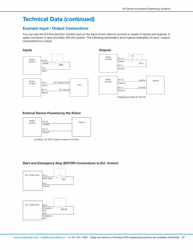
GV Series Automated Dispensing Systems
97www.nordsonefd.com [email protected] +1-401-431-7000 Sales and service of Nordson EFD dispensing systems are available worldwide.
Example Input / Output ConnectionsYou can use the I/O Port and Ext. Control port on the back of the robot to connect a variety of inputs and outputs. A spare connector is also provided with the system. The following schematics show typical examples of input / output connections to a robot.
Inputs
Pin 25
PLC Output (+24V)PLC
SW1
Robot I/O Port
+24VDC
Robot I/O Port
Pin 2
Input 2
Pin 11
Ground
Pin 1
Input 1
PLC Ground
Outputs
External Device Powered by the Robot
Pin 24 DeviceRobot
I/O Port+24VDC
Pin 11
Ground
Courtesy +24 VDC output is rated at 3.0 Amp.
Start and Emergency Stop (ESTOP) Connections to Ext. Control
Pin 2
ESTOP
Start signal
Ext. Control port
Pin 7
Emergency stop
Pin 1
Ground
Ext. Control port
SW1
Pin 6Emergency stop
Pin 14
+24V In Device
LED 1
Robot I/O Port
Output 1
Robot I/O Port
Pin 15
Output 2
Pin 11
Ground
Pin 11
Ground
Ground
Outputs are rated at 125 mA.
Technical Data (continued)
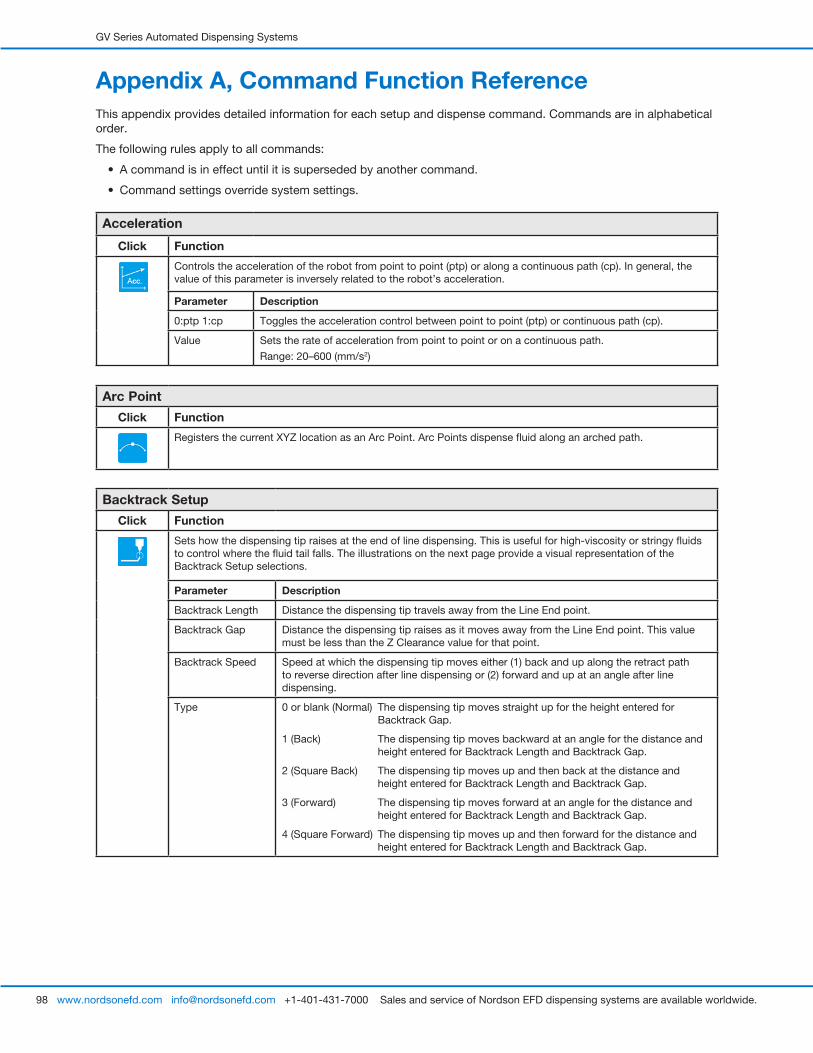
GV Series Automated Dispensing Systems
98 www.nordsonefd.com [email protected] +1-401-431-7000 Sales and service of Nordson EFD dispensing systems are available worldwide.
Appendix A, Command Function ReferenceThis appendix provides detailed information for each setup and dispense command. Commands are in alphabetical order.
The following rules apply to all commands:
• A command is in effect until it is superseded by another command.
• Command settings override system settings.
Acceleration
Click Function
Controls the acceleration of the robot from point to point (ptp) or along a continuous path (cp). In general, the value of this parameter is inversely related to the robot’s acceleration.
Parameter Description
0:ptp 1:cp Toggles the acceleration control between point to point (ptp) or continuous path (cp).
Value Sets the rate of acceleration from point to point or on a continuous path.
Range: 20–600 (mm/s2)
Arc Point
Click Function
Registers the current XYZ location as an Arc Point. Arc Points dispense fluid along an arched path.
Backtrack Setup
Click Function
Sets how the dispensing tip raises at the end of line dispensing. This is useful for high-viscosity or stringy fluids to control where the fluid tail falls. The illustrations on the next page provide a visual representation of the Backtrack Setup selections.
Parameter Description
Backtrack Length Distance the dispensing tip travels away from the Line End point.
Backtrack Gap Distance the dispensing tip raises as it moves away from the Line End point. This value must be less than the Z Clearance value for that point.
Backtrack Speed Speed at which the dispensing tip moves either (1) back and up along the retract path to reverse direction after line dispensing or (2) forward and up at an angle after line dispensing.
Type 0 or blank (Normal) The dispensing tip moves straight up for the height entered for Backtrack Gap.
1 (Back) The dispensing tip moves backward at an angle for the distance and height entered for Backtrack Length and Backtrack Gap.
2 (Square Back) The dispensing tip moves up and then back at the distance and height entered for Backtrack Length and Backtrack Gap.
3 (Forward) The dispensing tip moves forward at an angle for the distance and height entered for Backtrack Length and Backtrack Gap.
4 (Square Forward) The dispensing tip moves up and then forward for the distance and height entered for Backtrack Length and Backtrack Gap.
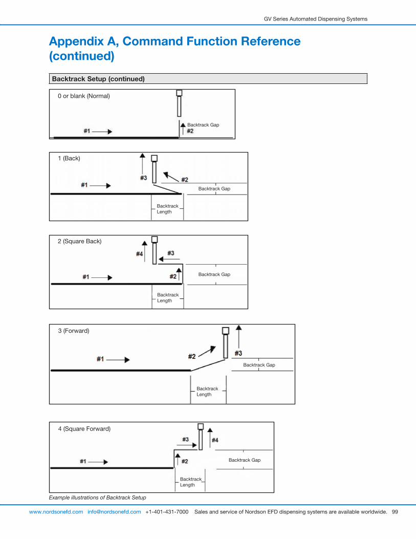
GV Series Automated Dispensing Systems
99www.nordsonefd.com [email protected] +1-401-431-7000 Sales and service of Nordson EFD dispensing systems are available worldwide.
Appendix A, Command Function Reference (continued)
Backtrack Setup (continued)
Example illustrations of Backtrack Setup
0 or blank (Normal)
Backtrack Gap
1 (Back)
Backtrack Gap
Backtrack Length
2 (Square Back)
Backtrack Gap
Backtrack Length
3 (Forward)
Backtrack Gap
Backtrack Length
4 (Square Forward)
Backtrack Gap
Backtrack Length

GV Series Automated Dispensing Systems
100 www.nordsonefd.com [email protected] +1-401-431-7000 Sales and service of Nordson EFD dispensing systems are available worldwide.
Appendix A, Command Function Reference (continued)
Block Initialize
Click Function
Double-click address and select from drop-down menu
When two Step & Repeat Block commands are present in a program, use Block Initialize to specify only the points that are selected in the Run Block Select window. Refer to “How to Disable Dispensing for Specific Workpieces in an Array” on page 69 for details.
Call Pattern
Click Function
Double-click address and select from drop-down menu
Causes the system to dispense in a pattern that is like another pattern in the program, but at the location in the program where the Call Pattern command occurs. The called pattern must have a Label assigned to it. The system stops dispensing the called pattern when it reaches an End Pattern command.
Example of a program that includes a Call Pattern command
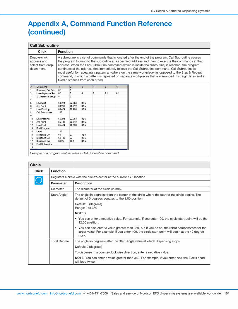
GV Series Automated Dispensing Systems
101www.nordsonefd.com [email protected] +1-401-431-7000 Sales and service of Nordson EFD dispensing systems are available worldwide.
Appendix A, Command Function Reference (continued)
Call Subroutine
Click Function
Double-click address and select from drop-down menu
A subroutine is a set of commands that is located after the end of the program. Call Subroutine causes the program to jump to the subroutine at a specified address and then to execute the commands at that address. When the End Subroutine command (which is inside the subroutine) is reached, the program continues at the address that immediately follows the Call Subroutine command. Call Subroutine is most useful for repeating a pattern anywhere on the same workpiece (as opposed to the Step & Repeat command, in which a pattern is repeated on separate workpieces that are arranged in straight lines and at fixed distances from each other).
Example of a program that includes a Call Subroutine command
Circle
Click Function
Registers a circle with the circle’s center at the current XYZ location
Parameter Description
Diameter The diameter of the circle (in mm)
Start Angle The angle (in degrees) from the center of the circle where the start of the circle begins. The default of 0 degrees equates to the 3:00 position.
Default: 0 (degrees) Range: 0 to 360
NOTES:
• You can enter a negative value. For example, if you enter -90, the circle start point will be the 12:00 position.
• You can also enter a value greater than 360, but if you do so, the robot compensates for the larger value. For example, if you enter 400, the circle start point will begin at the 40 degree mark.
Total Degree The angle (in degrees) after the Start Angle value at which dispensing stops.
Default: 0 (degrees)
To dispense in a counterclockwise direction, enter a negative value.
NOTE: You can enter a value greater than 360. For example, if you enter 720, the Z axis head will loop twice.
GV Series Automated Dispensing Systems
102 www.nordsonefd.com [email protected] +1-401-431-7000 Sales and service of Nordson EFD dispensing systems are available worldwide.
Appendix A, Command Function Reference (continued)
Circle 3 Point
Click Function
Double-click address and select from drop-down menu
Used in tandem with the Circle Run command when a circle is too large to fit in the Secondary View screen (in the CCD Mode). A larger circle can be created by entering three (3) Circle 3 Point commands, one for each “corner” of the circle. The system uses the three Circle 3 Point commands to calculate the entire circumference of the circle. The Circle Run command dictates where the circle starts and how many degrees the circle will be. The correct sequence of commands is: three (3)Circle 3 Point commands followed by one (1) Circle Run command.
Circle Run
Click Function
Double-click address and select from drop-down menu
Used in tandem with the Circle 3 Point command when a circle is too large to fit in the Secondary View screen (in the CCD Mode), adjusts the Start Angle and Total Degrees of the large circle.
Parameter Description
Start Angle The angle (in degrees) from the center of the circle where the start of the circle begins. The default of 0 degrees equates to the 3:00 position.
Default: 0 (degrees) Range: 0 to 360
NOTES:
• You can enter a negative value. For example, if you enter -90, the circle start point will be the 12:00 position.
• You can also enter a value greater than 360, but if you do so, the robot compensates for the larger value. For example, if you enter 400, the circle start point will begin at the 40 degree mark.
Total Degree The angle (in degrees) after the Start Angle value at which dispensing stops.
Default: 0 (degrees)
To dispense in a counterclockwise direction, enter a negative value.
NOTE: You can enter a value greater than 360. For example, if you enter 720, the Z axis head will loop twice.
Dispense Dot
Click Function
Registers the current XYZ location as a Dispense Dot point.
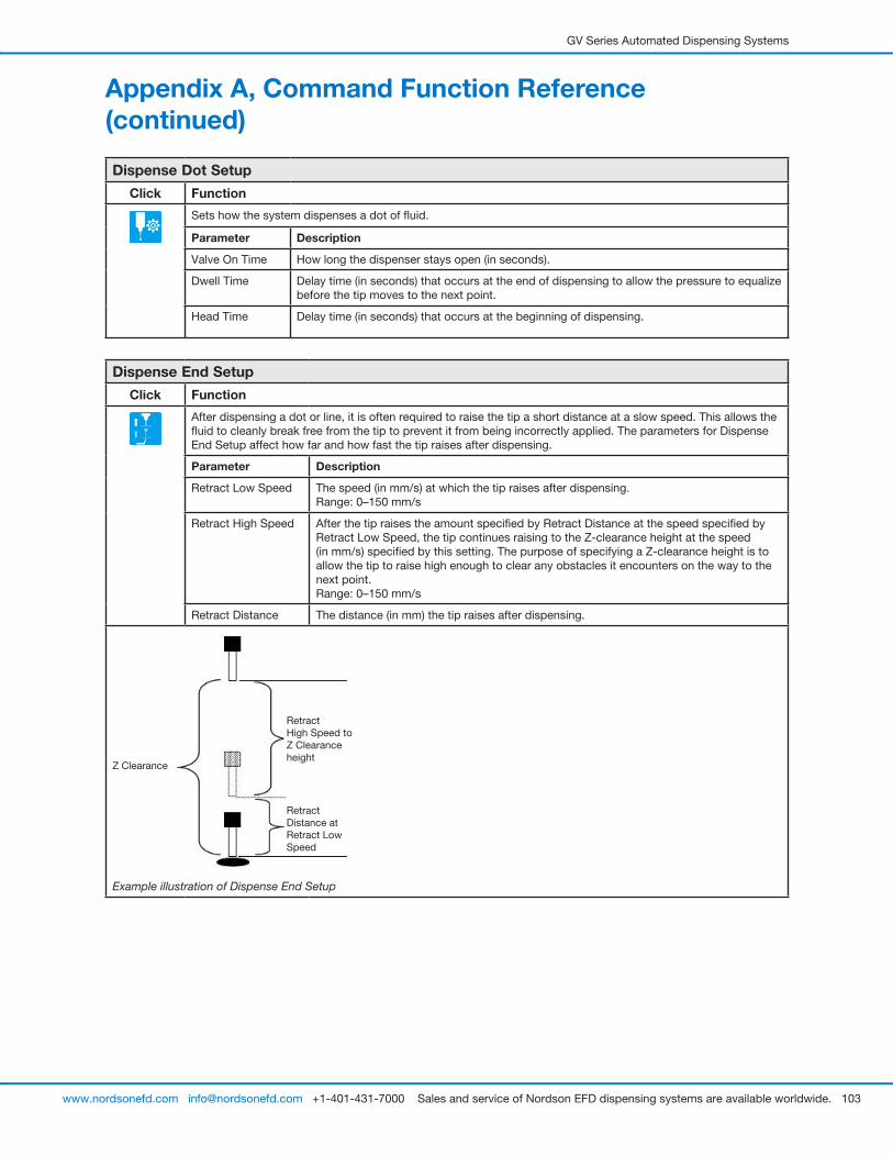
GV Series Automated Dispensing Systems
103www.nordsonefd.com [email protected] +1-401-431-7000 Sales and service of Nordson EFD dispensing systems are available worldwide.
Appendix A, Command Function Reference (continued)
Dispense Dot Setup
Click Function
Sets how the system dispenses a dot of fluid.
Parameter Description
Valve On Time How long the dispenser stays open (in seconds).
Dwell Time Delay time (in seconds) that occurs at the end of dispensing to allow the pressure to equalize before the tip moves to the next point.
Head Time Delay time (in seconds) that occurs at the beginning of dispensing.
Dispense End Setup
Click Function
After dispensing a dot or line, it is often required to raise the tip a short distance at a slow speed. This allows the fluid to cleanly break free from the tip to prevent it from being incorrectly applied. The parameters for Dispense End Setup affect how far and how fast the tip raises after dispensing.
Parameter Description
Retract Low Speed The speed (in mm/s) at which the tip raises after dispensing.Range: 0–150 mm/s
Retract High Speed After the tip raises the amount specified by Retract Distance at the speed specified by Retract Low Speed, the tip continues raising to the Z-clearance height at the speed (in mm/s) specified by this setting. The purpose of specifying a Z-clearance height is to allow the tip to raise high enough to clear any obstacles it encounters on the way to the next point.Range: 0–150 mm/s
Retract Distance The distance (in mm) the tip raises after dispensing.
Z Clearance
Retract High Speed to Z Clearance height
Retract Distance at Retract Low Speed
Example illustration of Dispense End Setup
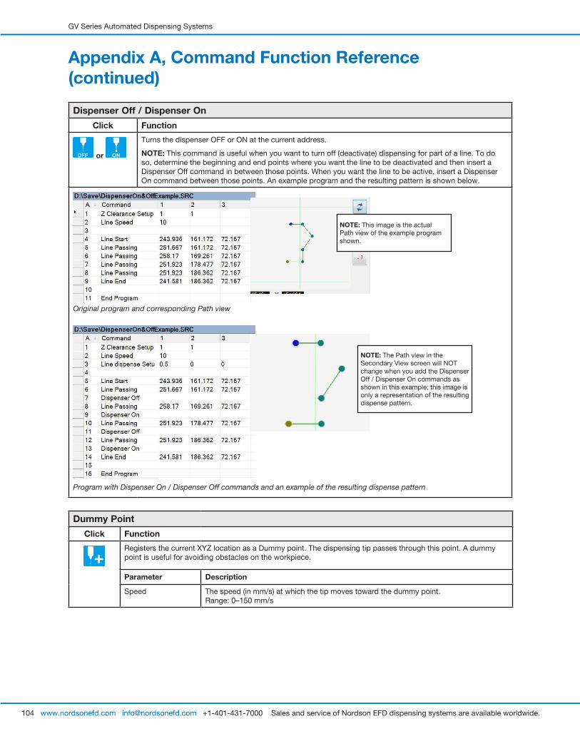
GV Series Automated Dispensing Systems
104 www.nordsonefd.com [email protected] +1-401-431-7000 Sales and service of Nordson EFD dispensing systems are available worldwide.
Appendix A, Command Function Reference (continued)
Dispenser Off / Dispenser On
Click Function
or
Turns the dispenser OFF or ON at the current address.
NOTE: This command is useful when you want to turn off (deactivate) dispensing for part of a line. To do so, determine the beginning and end points where you want the line to be deactivated and then insert a Dispenser Off command in between those points. When you want the line to be active, insert a Dispenser On command between those points. An example program and the resulting pattern is shown below.
Original program and corresponding Path view
Program with Dispenser On / Dispenser Off commands and an example of the resulting dispense pattern
NOTE: The Path view in the Secondary View screen will NOT change when you add the Dispenser Off / Dispenser On commands as shown in this example; this image is only a representation of the resulting dispense pattern.
NOTE: This image is the actual Path view of the example program shown.
Dummy Point
Click Function
Registers the current XYZ location as a Dummy point. The dispensing tip passes through this point. A dummy point is useful for avoiding obstacles on the workpiece.
Parameter Description
Speed The speed (in mm/s) at which the tip moves toward the dummy point.Range: 0–150 mm/s
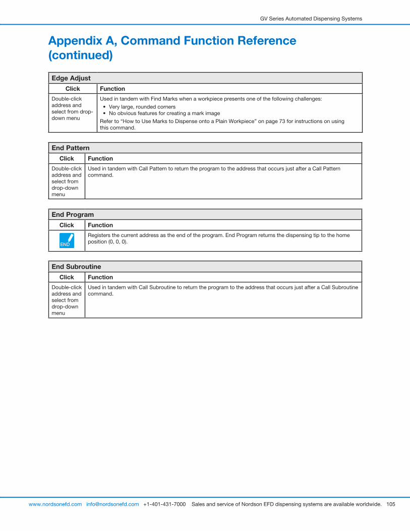
GV Series Automated Dispensing Systems
105www.nordsonefd.com [email protected] +1-401-431-7000 Sales and service of Nordson EFD dispensing systems are available worldwide.
Edge Adjust
Click Function
Double-click address and select from drop-down menu
Used in tandem with Find Marks when a workpiece presents one of the following challenges:
• Very large, rounded corners• No obvious features for creating a mark image
Refer to “How to Use Marks to Dispense onto a Plain Workpiece” on page 73 for instructions on using this command.
End Pattern
Click Function
Double-click address and select from drop-down menu
Used in tandem with Call Pattern to return the program to the address that occurs just after a Call Pattern command.
End Program
Click Function
Registers the current address as the end of the program. End Program returns the dispensing tip to the home position (0, 0, 0).
End Subroutine
Click Function
Double-click address and select from drop-down menu
Used in tandem with Call Subroutine to return the program to the address that occurs just after a Call Subroutine command.
Appendix A, Command Function Reference (continued)
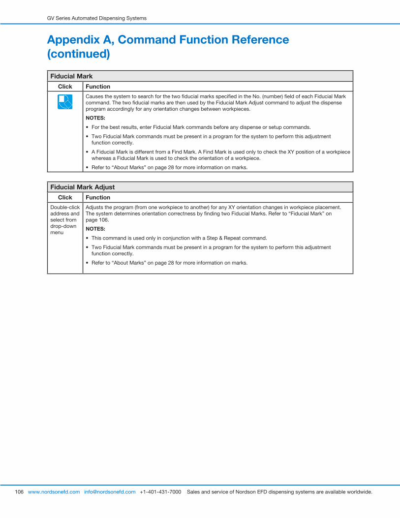
GV Series Automated Dispensing Systems
106 www.nordsonefd.com [email protected] +1-401-431-7000 Sales and service of Nordson EFD dispensing systems are available worldwide.
Fiducial Mark
Click Function
Causes the system to search for the two fiducial marks specified in the No. (number) field of each Fiducial Mark command. The two fiducial marks are then used by the Fiducial Mark Adjust command to adjust the dispense program accordingly for any orientation changes between workpieces.
NOTES:
• For the best results, enter Fiducial Mark commands before any dispense or setup commands.
• Two Fiducial Mark commands must be present in a program for the system to perform this adjustment function correctly.
• A Fiducial Mark is different from a Find Mark. A Find Mark is used only to check the XY position of a workpiece whereas a Fiducial Mark is used to check the orientation of a workpiece.
• Refer to “About Marks” on page 28 for more information on marks.
Fiducial Mark Adjust
Click Function
Double-click address and select from drop-down menu
Adjusts the program (from one workpiece to another) for any XY orientation changes in workpiece placement. The system determines orientation correctness by finding two Fiducial Marks. Refer to “Fiducial Mark” on page 106.
NOTES:
• This command is used only in conjunction with a Step & Repeat command.
• Two Fiducial Mark commands must be present in a program for the system to perform this adjustment function correctly.
• Refer to “About Marks” on page 28 for more information on marks.
Appendix A, Command Function Reference (continued)
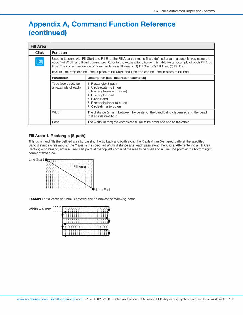
GV Series Automated Dispensing Systems
107www.nordsonefd.com [email protected] +1-401-431-7000 Sales and service of Nordson EFD dispensing systems are available worldwide.
Fill Area: 1. Rectangle (S path)This command fills the defined area by passing the tip back and forth along the X axis (in an S-shaped path) at the specified Band distance while moving the Y axis in the specified Width distance after each pass along the X axis. After entering a Fill Area Rectangle command, enter a Line Start point at the top left corner of the area to be filled and a Line End point at the bottom right corner of that area.
Line Start
Line End
Fill Area
EXAMPLE: if a Width of 5 mm is entered, the tip makes the following path:
Width = 5 mm
Fill Area
Click Function
Used in tandem with Fill Start and Fill End, the Fill Area command fills a defined area in a specific way using the specified Width and Band parameters. Refer to the explanations below this table for an example of each Fill Area type. The correct sequence of commands for a fill area is: (1) Fill Start, (2) Fill Area, (3) Fill End.
NOTE: Line Start can be used in place of Fill Start, and Line End can be used in place of Fill End.
Parameter Description (see illustration examples)
Type (see below for an example of each)
1. Rectangle (S path) 2. Circle (outer to inner) 3. Rectangle (outer to inner) 4. Rectangle Band 5. Circle Band 6. Rectangle (inner to outer) 7. Circle (inner to outer)
Width The distance (in mm) between the center of the bead being dispensed and the bead that spirals next to it.
Band The width (in mm) the completed fill must be (from one end to the other).
Appendix A, Command Function Reference (continued)
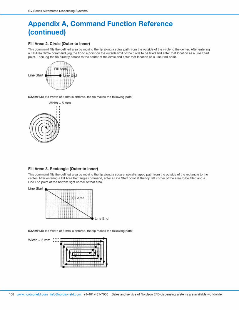
GV Series Automated Dispensing Systems
108 www.nordsonefd.com [email protected] +1-401-431-7000 Sales and service of Nordson EFD dispensing systems are available worldwide.
Fill Area: 2. Circle (Outer to Inner)This command fills the defined area by moving the tip along a spiral path from the outside of the circle to the center. After entering a Fill Area Circle command, jog the tip to a point on the outside limit of the circle to be filled and enter that location as a Line Start point. Then jog the tip directly across to the center of the circle and enter that location as a Line End point.
Line EndLine Start
Fill Area
EXAMPLE: if a Width of 5 mm is entered, the tip makes the following path:
Width = 5 mm
Fill Area: 3. Rectangle (Outer to Inner)This command fills the defined area by moving the tip along a square, spiral-shaped path from the outside of the rectangle to the center. After entering a Fill Area Rectangle command, enter a Line Start point at the top left corner of the area to be filled and a Line End point at the bottom right corner of that area.
Line Start
Line End
Fill Area
EXAMPLE: If a Width of 5 mm is entered, the tip makes the following path:
Width = 5 mm
Appendix A, Command Function Reference (continued)
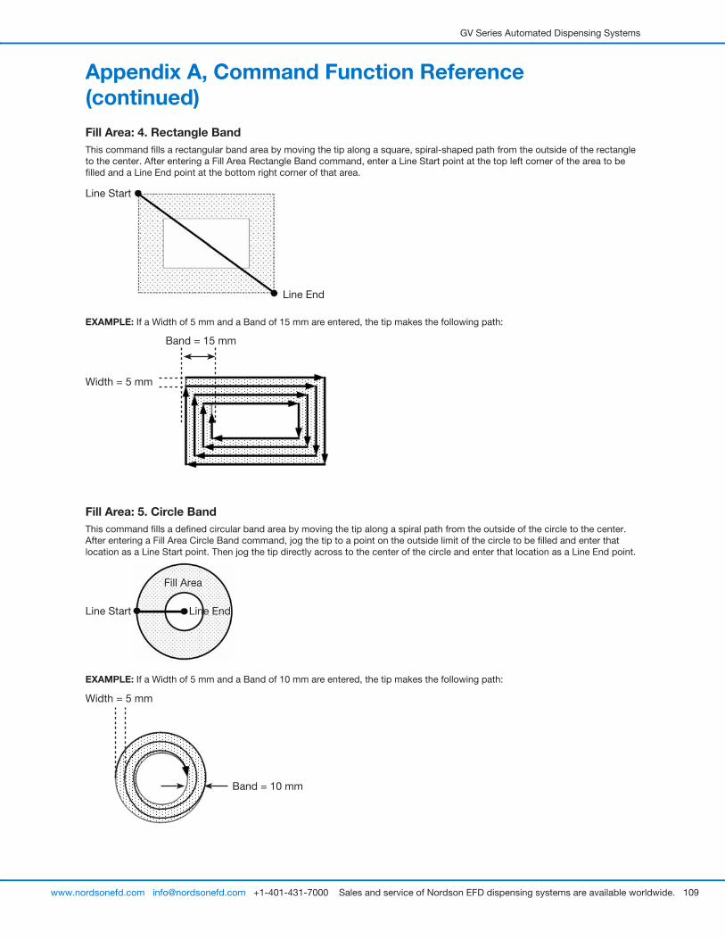
GV Series Automated Dispensing Systems
109www.nordsonefd.com [email protected] +1-401-431-7000 Sales and service of Nordson EFD dispensing systems are available worldwide.
Fill Area: 4. Rectangle BandThis command fills a rectangular band area by moving the tip along a square, spiral-shaped path from the outside of the rectangle to the center. After entering a Fill Area Rectangle Band command, enter a Line Start point at the top left corner of the area to be filled and a Line End point at the bottom right corner of that area.
Line Start
Line End
EXAMPLE: If a Width of 5 mm and a Band of 15 mm are entered, the tip makes the following path:
Band = 15 mm
Width = 5 mm
Fill Area: 5. Circle BandThis command fills a defined circular band area by moving the tip along a spiral path from the outside of the circle to the center. After entering a Fill Area Circle Band command, jog the tip to a point on the outside limit of the circle to be filled and enter that location as a Line Start point. Then jog the tip directly across to the center of the circle and enter that location as a Line End point.
Line EndLine Start
Fill Area
EXAMPLE: If a Width of 5 mm and a Band of 10 mm are entered, the tip makes the following path:
Band = 10 mm
Width = 5 mm
Appendix A, Command Function Reference (continued)
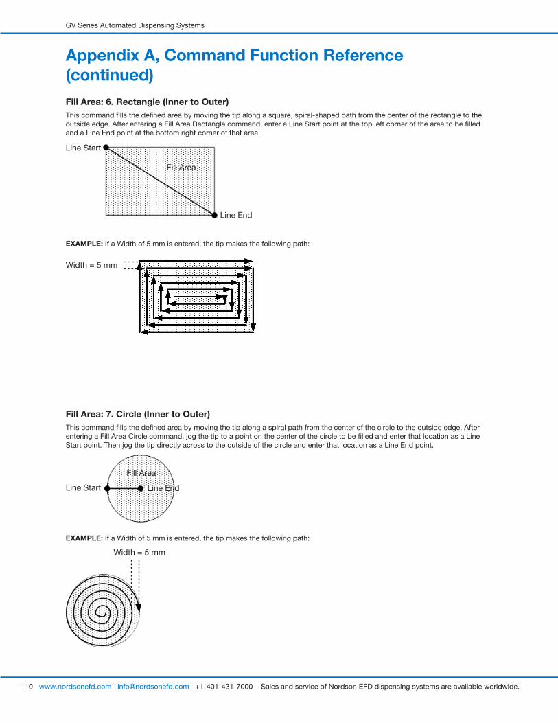
GV Series Automated Dispensing Systems
110 www.nordsonefd.com [email protected] +1-401-431-7000 Sales and service of Nordson EFD dispensing systems are available worldwide.
Fill Area: 6. Rectangle (Inner to Outer)This command fills the defined area by moving the tip along a square, spiral-shaped path from the center of the rectangle to the outside edge. After entering a Fill Area Rectangle command, enter a Line Start point at the top left corner of the area to be filled and a Line End point at the bottom right corner of that area.
Line Start
Line End
Fill Area
EXAMPLE: If a Width of 5 mm is entered, the tip makes the following path:
Width = 5 mm
Fill Area: 7. Circle (Inner to Outer)This command fills the defined area by moving the tip along a spiral path from the center of the circle to the outside edge. After entering a Fill Area Circle command, jog the tip to a point on the center of the circle to be filled and enter that location as a Line Start point. Then jog the tip directly across to the outside of the circle and enter that location as a Line End point.
Line EndLine Start
Fill Area
EXAMPLE: If a Width of 5 mm is entered, the tip makes the following path:
Width = 5 mm
Appendix A, Command Function Reference (continued)
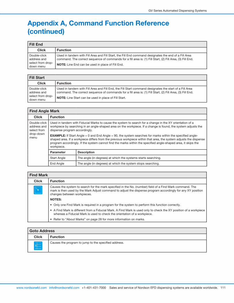
GV Series Automated Dispensing Systems
111www.nordsonefd.com [email protected] +1-401-431-7000 Sales and service of Nordson EFD dispensing systems are available worldwide.
Fill EndClick Function
Double-click address and select from drop-down menu
Used in tandem with Fill Area and Fill Start, the Fill End command designates the end of a Fill Area command. The correct sequence of commands for a fill area is: (1) Fill Start, (2) Fill Area, (3) Fill End.
NOTE: Line End can be used in place of Fill End.
Fill StartClick Function
Double-click address and select from drop-down menu
Used in tandem with Fill Area and Fill End, the Fill Start command designates the start of a Fill Area command. The correct sequence of commands for a fill area is: (1) Fill Start, (2) Fill Area, (3) Fill End.
NOTE: Line Start can be used in place of Fill Start.
Find Angle Mark
Click Function
Double-click address and select from drop-down menu
Used in tandem with Fiducial Marks to cause the system to search for a change in the XY orientation of a workpiece by searching in an angle-shaped area on the workpiece. If a change is found, the system adjusts the dispense program accordingly.
EXAMPLE: If Start Angle = 0 and End Angle = 90, the system searches for marks within the specified angle-shaped area. If a workpiece differs from the previous workpiece within that area, the system adjusts the dispense program accordingly. If the system cannot find the marks within the specified angle-shaped area, it skips the workpiece.
Parameter Description
Start Angle The angle (in degrees) at which the systems starts searching.
End Angle The angle (in degrees) at which the system stops searching.
Find Mark
Click Function
Causes the system to search for the mark specified in the No. (number) field of a Find Mark command. The mark is then used by the Mark Adjust command to adjust the dispense program accordingly for any XY position changes between workpieces.
NOTES:
• Only one Find Mark is required in a program for the system to perform this function correctly.
• A Find Mark is different from a Fiducial Mark. A Find Mark is used only to check the XY position of a workpiece whereas a Fiducial Mark is used to check the orientation of a workpiece.
• Refer to “About Marks” on page 28 for more information on marks.
Goto Address
Click Function
Causes the program to jump to the specified address.
Appendix A, Command Function Reference (continued)
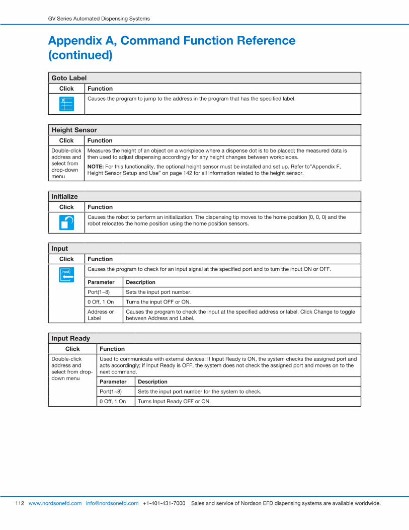
GV Series Automated Dispensing Systems
112 www.nordsonefd.com [email protected] +1-401-431-7000 Sales and service of Nordson EFD dispensing systems are available worldwide.
Goto Label
Click Function
Causes the program to jump to the address in the program that has the specified label.
Height Sensor
Click Function
Double-click address and select from drop-down menu
Measures the height of an object on a workpiece where a dispense dot is to be placed; the measured data is then used to adjust dispensing accordingly for any height changes between workpieces.
NOTE: For this functionality, the optional height sensor must be installed and set up. Refer to”Appendix F, Height Sensor Setup and Use” on page 142 for all information related to the height sensor.
Initialize
Click Function
Causes the robot to perform an initialization. The dispensing tip moves to the home position (0, 0, 0) and the robot relocates the home position using the home position sensors.
Input
Click Function
Causes the program to check for an input signal at the specified port and to turn the input ON or OFF.
Parameter Description
Port(1~8) Sets the input port number.
0 Off, 1 On Turns the input OFF or ON.
Address or Label
Causes the program to check the input at the specified address or label. Click Change to toggle between Address and Label.
Input Ready
Click Function
Double-click address and select from drop-down menu
Used to communicate with external devices: If Input Ready is ON, the system checks the assigned port and acts accordingly; if Input Ready is OFF, the system does not check the assigned port and moves on to the next command.
Parameter Description
Port(1~8) Sets the input port number for the system to check.
0 Off, 1 On Turns Input Ready OFF or ON.
Appendix A, Command Function Reference (continued)
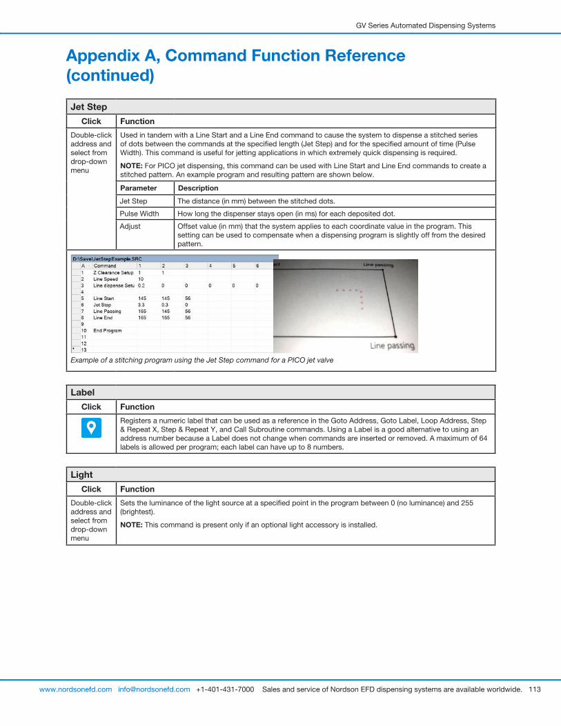
GV Series Automated Dispensing Systems
113www.nordsonefd.com [email protected] +1-401-431-7000 Sales and service of Nordson EFD dispensing systems are available worldwide.
Jet Step
Click Function
Double-click address and select from drop-down menu
Used in tandem with a Line Start and a Line End command to cause the system to dispense a stitched series of dots between the commands at the specified length (Jet Step) and for the specified amount of time (Pulse Width). This command is useful for jetting applications in which extremely quick dispensing is required.
NOTE: For PICO jet dispensing, this command can be used with Line Start and Line End commands to create a stitched pattern. An example program and resulting pattern are shown below.
Parameter Description
Jet Step The distance (in mm) between the stitched dots.
Pulse Width How long the dispenser stays open (in ms) for each deposited dot.
Adjust Offset value (in mm) that the system applies to each coordinate value in the program. This setting can be used to compensate when a dispensing program is slightly off from the desired pattern.
Example of a stitching program using the Jet Step command for a PICO jet valve
Label
Click Function
Registers a numeric label that can be used as a reference in the Goto Address, Goto Label, Loop Address, Step & Repeat X, Step & Repeat Y, and Call Subroutine commands. Using a Label is a good alternative to using an address number because a Label does not change when commands are inserted or removed. A maximum of 64 labels is allowed per program; each label can have up to 8 numbers.
Light
Click Function
Double-click address and select from drop-down menu
Sets the luminance of the light source at a specified point in the program between 0 (no luminance) and 255 (brightest).
NOTE: This command is present only if an optional light accessory is installed.
Appendix A, Command Function Reference (continued)
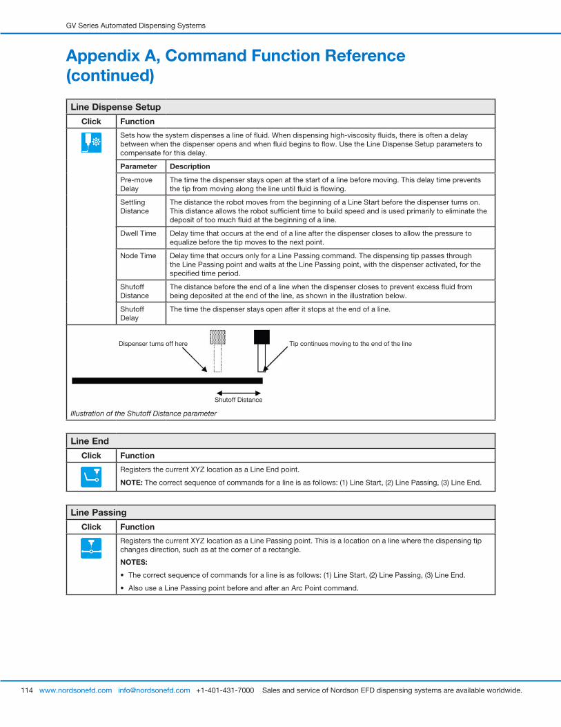
GV Series Automated Dispensing Systems
114 www.nordsonefd.com [email protected] +1-401-431-7000 Sales and service of Nordson EFD dispensing systems are available worldwide.
Appendix A, Command Function Reference (continued)
Line Dispense Setup
Click Function
Sets how the system dispenses a line of fluid. When dispensing high-viscosity fluids, there is often a delay between when the dispenser opens and when fluid begins to flow. Use the Line Dispense Setup parameters to compensate for this delay.
Parameter Description
Pre-move Delay
The time the dispenser stays open at the start of a line before moving. This delay time prevents the tip from moving along the line until fluid is flowing.
Settling Distance
The distance the robot moves from the beginning of a Line Start before the dispenser turns on. This distance allows the robot sufficient time to build speed and is used primarily to eliminate the deposit of too much fluid at the beginning of a line.
Dwell Time Delay time that occurs at the end of a line after the dispenser closes to allow the pressure to equalize before the tip moves to the next point.
Node Time Delay time that occurs only for a Line Passing command. The dispensing tip passes through the Line Passing point and waits at the Line Passing point, with the dispenser activated, for the specified time period.
Shutoff Distance
The distance before the end of a line when the dispenser closes to prevent excess fluid from being deposited at the end of the line, as shown in the illustration below.
Shutoff Delay
The time the dispenser stays open after it stops at the end of a line.
Shutoff Distance
Tip continues moving to the end of the lineDispenser turns off here
Illustration of the Shutoff Distance parameter
Line End
Click Function
Registers the current XYZ location as a Line End point.
NOTE: The correct sequence of commands for a line is as follows: (1) Line Start, (2) Line Passing, (3) Line End.
Line Passing
Click Function
Registers the current XYZ location as a Line Passing point. This is a location on a line where the dispensing tip changes direction, such as at the corner of a rectangle.
NOTES:
• The correct sequence of commands for a line is as follows: (1) Line Start, (2) Line Passing, (3) Line End.
• Also use a Line Passing point before and after an Arc Point command.
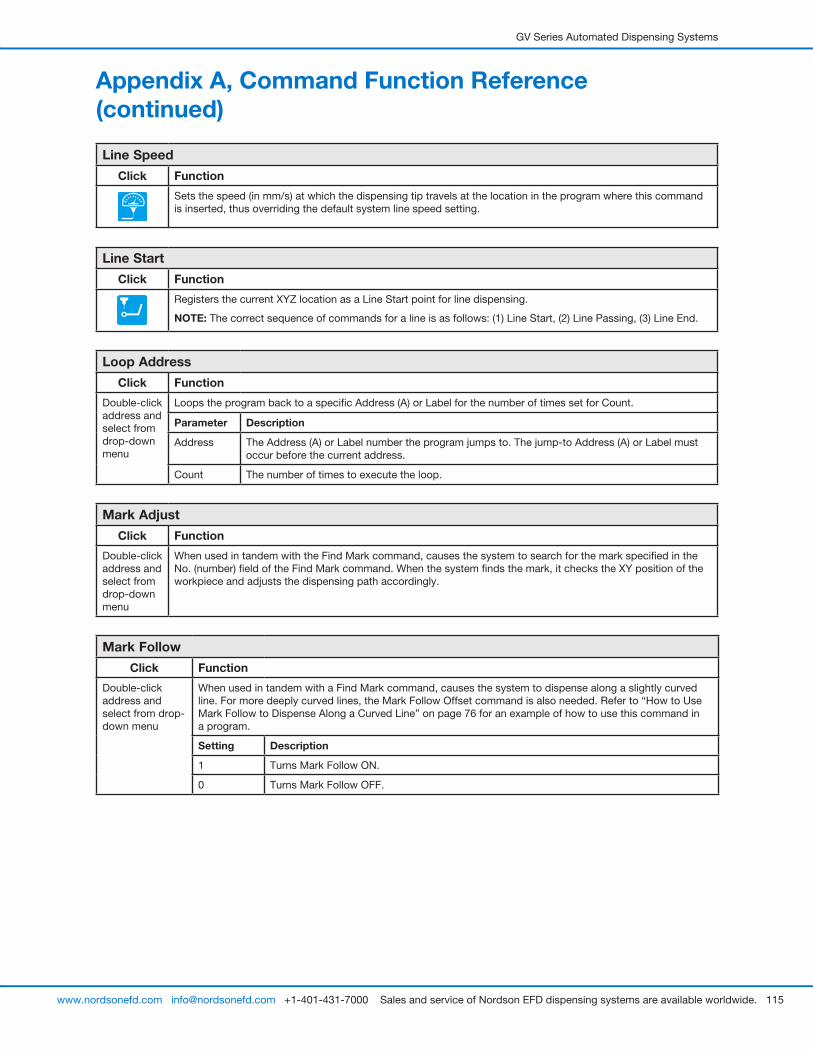
GV Series Automated Dispensing Systems
115www.nordsonefd.com [email protected] +1-401-431-7000 Sales and service of Nordson EFD dispensing systems are available worldwide.
Appendix A, Command Function Reference (continued)
Line Speed
Click Function
Sets the speed (in mm/s) at which the dispensing tip travels at the location in the program where this command is inserted, thus overriding the default system line speed setting.
Line Start
Click Function
Registers the current XYZ location as a Line Start point for line dispensing.
NOTE: The correct sequence of commands for a line is as follows: (1) Line Start, (2) Line Passing, (3) Line End.
Loop Address
Click Function
Double-click address and select from drop-down menu
Loops the program back to a specific Address (A) or Label for the number of times set for Count.
Parameter Description
Address The Address (A) or Label number the program jumps to. The jump-to Address (A) or Label must occur before the current address.
Count The number of times to execute the loop.
Mark Adjust
Click Function
Double-click address and select from drop-down menu
When used in tandem with the Find Mark command, causes the system to search for the mark specified in the No. (number) field of the Find Mark command. When the system finds the mark, it checks the XY position of the workpiece and adjusts the dispensing path accordingly.
Mark Follow
Click Function
Double-click address and select from drop-down menu
When used in tandem with a Find Mark command, causes the system to dispense along a slightly curved line. For more deeply curved lines, the Mark Follow Offset command is also needed. Refer to “How to Use Mark Follow to Dispense Along a Curved Line” on page 76 for an example of how to use this command in a program.
Setting Description
1 Turns Mark Follow ON.
0 Turns Mark Follow OFF.
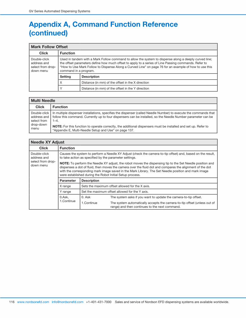
GV Series Automated Dispensing Systems
116 www.nordsonefd.com [email protected] +1-401-431-7000 Sales and service of Nordson EFD dispensing systems are available worldwide.
Mark Follow Offset
Click Function
Double-click address and select from drop-down menu
Used in tandem with a Mark Follow command to allow the system to dispense along a deeply curved line; the offset parameters define how much offset to apply to a series of Line Passing commands. Refer to “How to Use Mark Follow to Dispense Along a Curved Line” on page 76 for an example of how to use this command in a program.
Setting Description
X Distance (in mm) of the offset in the X direction
Y Distance (in mm) of the offset in the Y direction
Multi Needle
Click Function
Double-click address and select from drop-down menu
In multiple dispenser installations, specifies the dispenser (called Needle Number) to execute the commands that follow this command. Currently up to four dispensers can be installed, so the Needle Number parameter can be 1–4.
NOTE: For this function to operate correctly, the additional dispensers must be installed and set up. Refer to “Appendix E, Multi-Needle Setup and Use” on page 137.
Needle XY AdjustClick Function
Double-click address and select from drop-down menu
Causes the system to perform a Needle XY Adjust (check the camera-to-tip offset) and, based on the result, to take action as specified by the parameter settings.
NOTE: To perform the Needle XY adjust, the robot moves the dispensing tip to the Set Needle position and dispenses a dot of fluid, then moves the camera over the fluid dot and compares the alignment of the dot with the corresponding mark image saved in the Mark Library. The Set Needle position and mark image were established during the Robot Initial Setup process.
Parameter Description
X range Sets the maximum offset allowed for the X axis.
Y range Set the maximum offset allowed for the Y axis.
0.Ask, 1.Continue
0. Ask The system asks if you want to update the camera-to-tip offset.
1.Continue The system automatically accepts the camera-to-tip offset (unless out of range) and then continues to the next command.
Appendix A, Command Function Reference (continued)
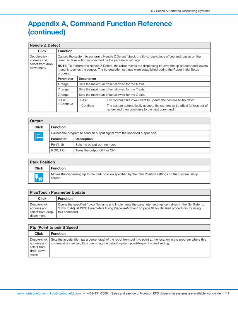
GV Series Automated Dispensing Systems
117www.nordsonefd.com [email protected] +1-401-431-7000 Sales and service of Nordson EFD dispensing systems are available worldwide.
Needle Z DetectClick Function
Double-click address and select from drop-down menu
Causes the system to perform a Needle Z Detect (check the tip-to-workpiece offset) and, based on the result, to take action as specified by the parameter settings.
NOTE: To perform the Needle Z Detect, the robot moves the dispensing tip over the tip detector and lowers it until it touches the sensor. The tip detection settings were established during the Robot Initial Setup process.
Parameter Description
X range Sets the maximum offset allowed for the X axis.
Y range Sets the maximum offset allowed for the Y axis.
Z range Sets the maximum offset allowed for the Z axis.
0.Ask, 1.Continue
0. Ask The system asks if you want to update the camera-to-tip offset.
1.Continue The system automatically accepts the camera-to-tip offset (unless out of range) and then continues to the next command.
Output
Click Function
Causes the program to send an output signal from the specified output port.
Parameter Description
Port(1~8) Sets the output port number.
0 Off, 1 On Turns the output OFF or ON.
Park Position
Click Function
Moves the dispensing tip to the park position specified by the Park Position settings on the System Setup screen.
PicoTouch Parameter Update
Click Function
Double-click address and select from drop-down menu
Opens the specified *.pico file name and implements the parameter settings contained in the file. Refer to “How to Adjust PICO Parameters Using DispenseMotion” on page 84 for detailed procedures for using this command.
Ptp (Point to point) Speed
Click Function
Double-click address and select from drop-down menu
Sets the acceleration (as a percentage) of the robot from point to point at the location in the program where this command is inserted, thus overriding the default system point-to-point speed setting.
Appendix A, Command Function Reference (continued)
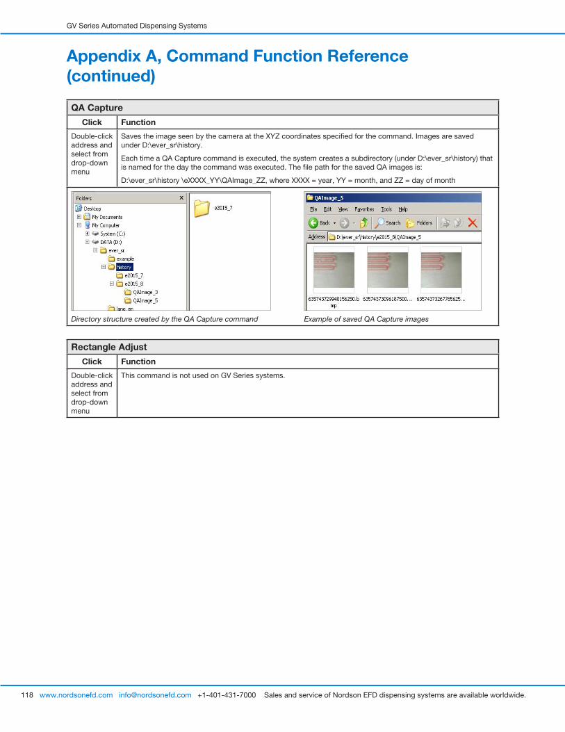
GV Series Automated Dispensing Systems
118 www.nordsonefd.com [email protected] +1-401-431-7000 Sales and service of Nordson EFD dispensing systems are available worldwide.
QA Capture
Click Function
Double-click address and select from drop-down menu
Saves the image seen by the camera at the XYZ coordinates specified for the command. Images are saved under D:\ever_sr\history.
Each time a QA Capture command is executed, the system creates a subdirectory (under D:\ever_sr\history) that is named for the day the command was executed. The file path for the saved QA images is:
D:\ever_sr\history \eXXXX_YY\QAImage_ZZ, where XXXX = year, YY = month, and ZZ = day of month
Directory structure created by the QA Capture command Example of saved QA Capture images
Rectangle Adjust
Click Function
Double-click address and select from drop-down menu
This command is not used on GV Series systems.
Appendix A, Command Function Reference (continued)
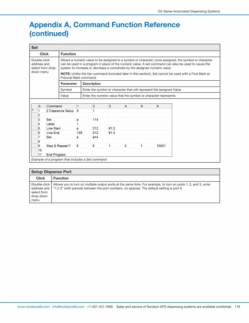
GV Series Automated Dispensing Systems
119www.nordsonefd.com [email protected] +1-401-431-7000 Sales and service of Nordson EFD dispensing systems are available worldwide.
Set
Click Function
Double-click address and select from drop-down menu
Allows a numeric value to be assigned to a symbol or character; once assigned, the symbol or character can be used in a program in place of the numeric value. A set command can also be used to cause the system to increase or decrease a coordinate by the assigned numeric value.
NOTE: Unlike the Var command (included later in this section), Set cannot be used with a Find Mark or Fiducial Mark command.
Parameter Description
Symbol Enter the symbol or character that will represent the assigned Value
Value Enter the numeric value that the symbol or character represents
Example of a program that includes a Set command
Setup Dispense Port
Click Function
Double-click address and select from drop-down menu
Allows you to turn on multiple output ports at the same time. For example, to turn on ports 1, 2, and 3, enter “1.2.3” (with periods between the port numbers, no spaces). The default setting is port 0.
Appendix A, Command Function Reference (continued)
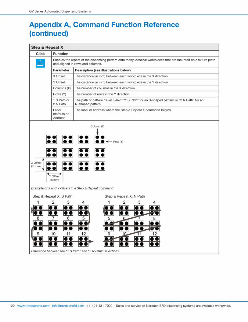
GV Series Automated Dispensing Systems
120 www.nordsonefd.com [email protected] +1-401-431-7000 Sales and service of Nordson EFD dispensing systems are available worldwide.
Appendix A, Command Function Reference (continued)
Step & Repeat X
Click Function
Enables the repeat of the dispensing pattern onto many identical workpieces that are mounted on a fixture plate and aligned in rows and columns.
Parameter Description (see illustrations below)
X Offset The distance (in mm) between each workpiece in the X direction.
Y Offset The distance (in mm) between each workpiece in the Y direction.
Columns (X) The number of columns in the X direction.
Rows (Y) The number of rows in the Y direction.
1.S Path or 2.N Path
The path of pattern travel. Select “1.S Path” for an S-shaped pattern or “2.N Path” for an N-shaped pattern.
Label (default) or Address
The label or address where the Step & Repeat X command begins.
X Offset (in mm)
Y Offset (in mm)
Row (Y)
Column (X)
Example of X and Y offsets in a Step & Repeat command
Step & Repeat X, S Path Step & Repeat X, N Path
Difference between the “1.S Path” and “2.N Path” selections
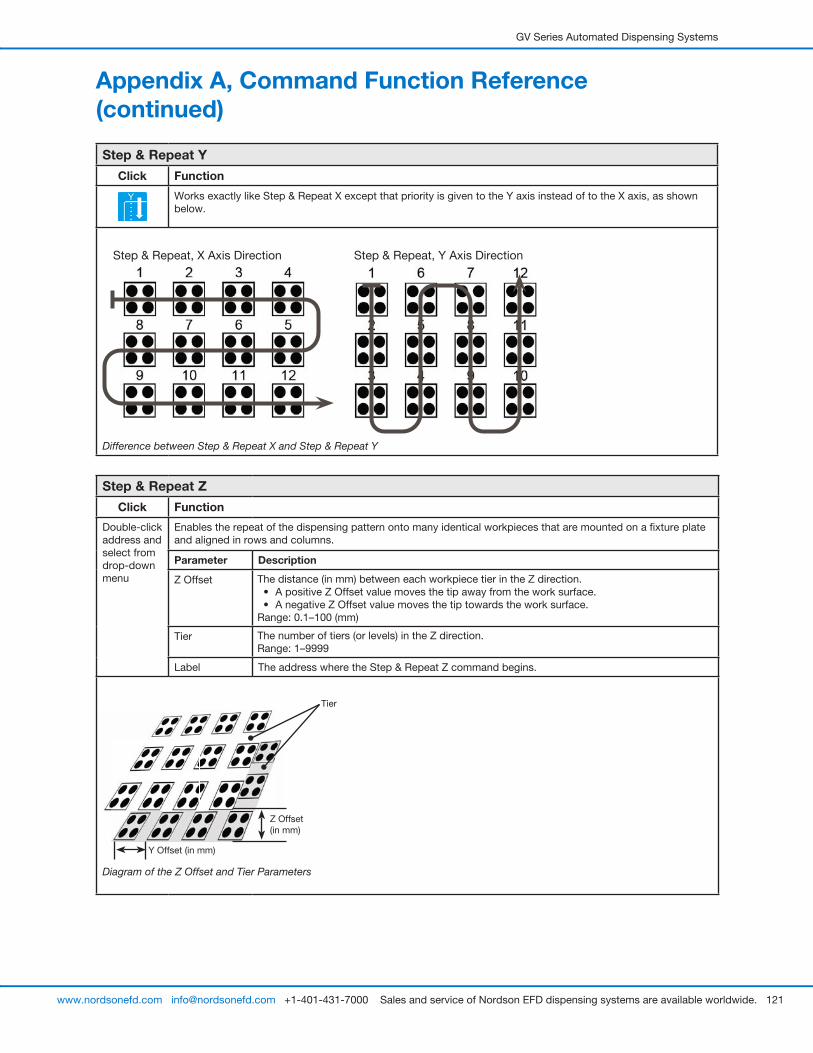
GV Series Automated Dispensing Systems
121www.nordsonefd.com [email protected] +1-401-431-7000 Sales and service of Nordson EFD dispensing systems are available worldwide.
Appendix A, Command Function Reference (continued)
Step & Repeat Y
Click Function
Works exactly like Step & Repeat X except that priority is given to the Y axis instead of to the X axis, as shown below.
Step & Repeat, X Axis Direction Step & Repeat, Y Axis Direction
Difference between Step & Repeat X and Step & Repeat Y
Step & Repeat Z
Click Function
Double-click address and select from drop-down menu
Enables the repeat of the dispensing pattern onto many identical workpieces that are mounted on a fixture plate and aligned in rows and columns.
Parameter Description
Z Offset The distance (in mm) between each workpiece tier in the Z direction.• A positive Z Offset value moves the tip away from the work surface.• A negative Z Offset value moves the tip towards the work surface.
Range: 0.1–100 (mm)
Tier The number of tiers (or levels) in the Z direction.Range: 1–9999
Label The address where the Step & Repeat Z command begins.
Y Offset (in mm)
Tier
Z Offset (in mm)
Diagram of the Z Offset and Tier Parameters

GV Series Automated Dispensing Systems
122 www.nordsonefd.com [email protected] +1-401-431-7000 Sales and service of Nordson EFD dispensing systems are available worldwide.
Appendix A, Command Function Reference (continued)
Stop Point
Click Function
Registers a Stop Point at the current XYZ location. When this command occurs, the dispensing tip moves to the registered location and waits until the START or CONTINUE button is pressed.
Trig Mark
Click Function
Double-click address and select from drop-down menu
This command is not used on GV Series systems.
Var
Click Function
Double-click address and select from drop-down menu
Allows a numeric value to be assigned to a symbol or character; once assigned, the symbol or character can be used in a program in place of the numeric value. A set command can also be used to cause the system to increase or decrease a coordinate by the assigned numeric value. Var can be used with the Find Mark and Fiducial Mark commands.
Parameter Description
Symbol Enter the symbol or character that will represent the assigned Value
Value Enter the numeric value that the symbol or character represents
Example of a program that includes a Var command
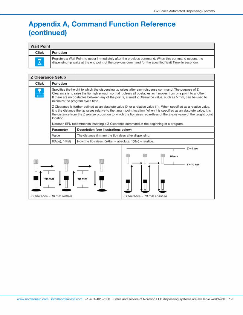
GV Series Automated Dispensing Systems
123www.nordsonefd.com [email protected] +1-401-431-7000 Sales and service of Nordson EFD dispensing systems are available worldwide.
Wait Point
Click Function
Registers a Wait Point to occur immediately after the previous command. When this command occurs, the dispensing tip waits at the end point of the previous command for the specified Wait Time (in seconds).
Z Clearance Setup
Click Function
Specifies the height to which the dispensing tip raises after each dispense command. The purpose of Z Clearance is to raise the tip high enough so that it clears all obstacles as it moves from one point to another. If there are no obstacles between any of the points, a small Z Clearance value, such as 5 mm, can be used to minimize the program cycle time.
Z Clearance is further defined as an absolute value (0) or a relative value (1) . When specified as a relative value, it is the distance the tip raises relative to the taught point location. When it is specified as an absolute value, it is the distance from the Z axis zero position to which the tip raises regardless of the Z-axis value of the taught point location.
Nordson EFD recommends inserting a Z Clearance command at the beginning of a program.
Parameter Description (see illustrations below)
Value The distance (in mm) the tip raises after dispensing.
0(Abs), 1(Rel) How the tip raises: 0(Abs) = absolute, 1(Rel) = relative.
Z Clearance = 10 mm relative Z Clearance = 10 mm absolute
Appendix A, Command Function Reference (continued)
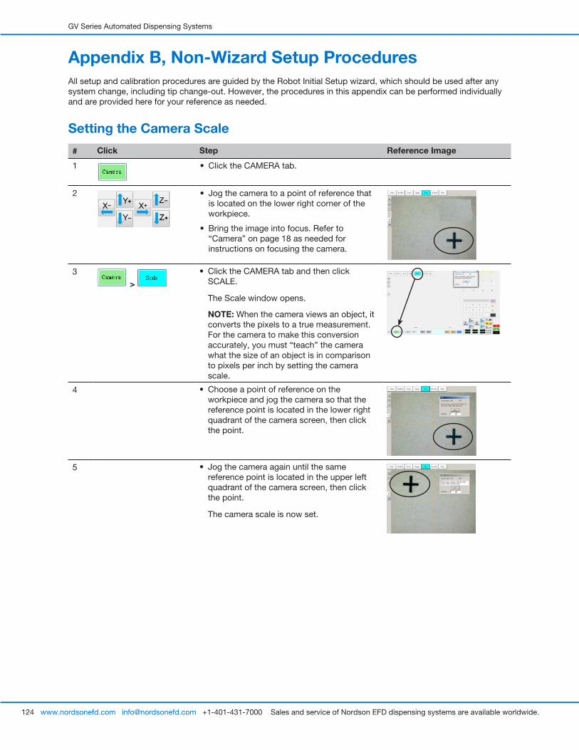
GV Series Automated Dispensing Systems
124 www.nordsonefd.com [email protected] +1-401-431-7000 Sales and service of Nordson EFD dispensing systems are available worldwide.
Appendix B, Non-Wizard Setup ProceduresAll setup and calibration procedures are guided by the Robot Initial Setup wizard, which should be used after any system change, including tip change-out. However, the procedures in this appendix can be performed individually and are provided here for your reference as needed.
Setting the Camera Scale
# Click Step Reference Image
1 • Click the CAMERA tab.
2 • Jog the camera to a point of reference that is located on the lower right corner of the workpiece.
• Bring the image into focus. Refer to “Camera” on page 18 as needed for instructions on focusing the camera.
3
>
• Click the CAMERA tab and then click SCALE.
The Scale window opens.
NOTE: When the camera views an object, it converts the pixels to a true measurement. For the camera to make this conversion accurately, you must “teach” the camera what the size of an object is in comparison to pixels per inch by setting the camera scale.
4 • Choose a point of reference on the workpiece and jog the camera so that the reference point is located in the lower right quadrant of the camera screen, then click the point.
5 • Jog the camera again until the same reference point is located in the upper left quadrant of the camera screen, then click the point.
The camera scale is now set.
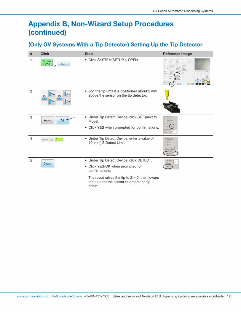
GV Series Automated Dispensing Systems
125www.nordsonefd.com [email protected] +1-401-431-7000 Sales and service of Nordson EFD dispensing systems are available worldwide.
(Only GV Systems With a Tip Detector) Setting Up the Tip Detector
# Click Step Reference Image
1
>
• Click SYSTEM SETUP > OPEN.
2 • Jog the tip until it is positioned about 2 mm above the sensor on the tip detector.
3 • Under Tip Detect Device, click SET (next to Move).
• Click YES when prompted for confirmations.
4 • Under Tip Detect Device, enter a value of 10 (mm) Z Detect Limit.
5 • Under Tip Detect Device, click DETECT.
• Click YES/OK when prompted for confirmations.
The robot raises the tip to Z = 0, then lowers the tip onto the sensor to detect the tip offset.
Appendix B, Non-Wizard Setup Procedures (continued)
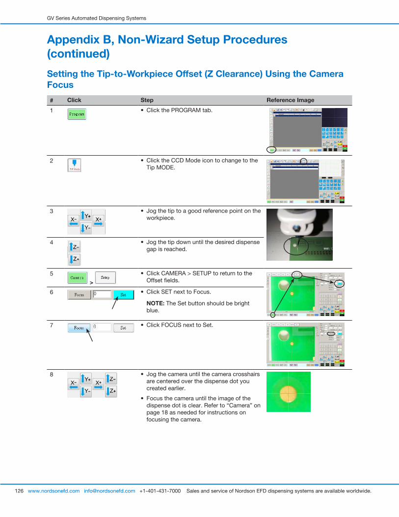
GV Series Automated Dispensing Systems
126 www.nordsonefd.com [email protected] +1-401-431-7000 Sales and service of Nordson EFD dispensing systems are available worldwide.
Setting the Tip-to-Workpiece Offset (Z Clearance) Using the Camera Focus
# Click Step Reference Image
1 • Click the PROGRAM tab.
2 • Click the CCD Mode icon to change to the Tip MODE.
3 • Jog the tip to a good reference point on the workpiece.
4 • Jog the tip down until the desired dispense gap is reached.
5
>
• Click CAMERA > SETUP to return to the Offset fields.
6 • Click SET next to Focus.
NOTE: The Set button should be bright blue.
7 • Click FOCUS next to Set.
8 • Jog the camera until the camera crosshairs are centered over the dispense dot you created earlier.
• Focus the camera until the image of the dispense dot is clear. Refer to “Camera” on page 18 as needed for instructions on focusing the camera.
Appendix B, Non-Wizard Setup Procedures (continued)
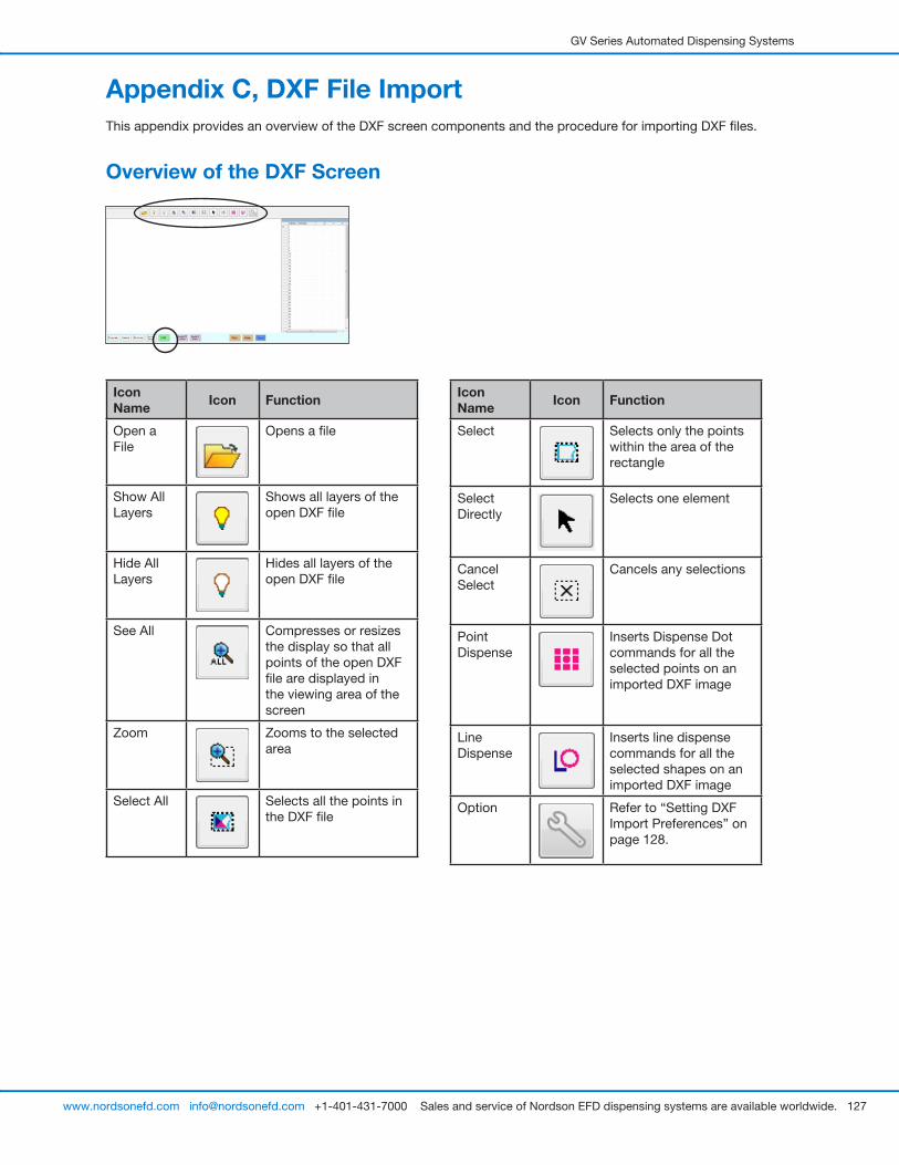
GV Series Automated Dispensing Systems
127www.nordsonefd.com [email protected] +1-401-431-7000 Sales and service of Nordson EFD dispensing systems are available worldwide.
Appendix C, DXF File ImportThis appendix provides an overview of the DXF screen components and the procedure for importing DXF files.
Overview of the DXF Screen
Icon Name Icon Function
Open a File
Opens a file
Show All Layers
Shows all layers of the open DXF file
Hide All Layers
Hides all layers of the open DXF file
See All Compresses or resizes the display so that all points of the open DXF file are displayed in the viewing area of the screen
Zoom Zooms to the selected area
Select All Selects all the points in the DXF file
Icon Name Icon Function
Select Selects only the points within the area of the rectangle
Select Directly
Selects one element
Cancel Select
Cancels any selections
Point Dispense
Inserts Dispense Dot commands for all the selected points on an imported DXF image
Line Dispense
Inserts line dispense commands for all the selected shapes on an imported DXF image
Option Refer to “Setting DXF Import Preferences” on page 128.

GV Series Automated Dispensing Systems
128 www.nordsonefd.com [email protected] +1-401-431-7000 Sales and service of Nordson EFD dispensing systems are available worldwide.
Setting DXF Import Preferences
Click the OPTION icon on the DXF screen to set DXF import preferences.
Appendix C, DXF File Import (continued)
Item Description
Spline Distance of points (mm)
Specifies the distance between any two points on a curve when the curve is converted to coordinates. For example, when this value is set to 1 and a 10-mm long curve is converted to commands, the result will be a series of Line Start, Line Passing, and Line End commands that will produce a curve with a total of 11 points.
Offset X, Y After you create program commands using Point Dispense or Line Dispense, the resulting XY values may be negative numbers. This causes the imported points to display off the grid when viewed on the Secondary View screen. To resolve this issue, enter X and / or Y values in the offset fields of the Option window such that the imported XY values change to positive values. For example, if an imported XY value is -150, -150, 0, then enter 200 for Offset X and 200 for offset Y, click OK, and then click the Point Dispense or Line Dispense icon again to refresh the values. The new values will be 50, 50, 0 and the points will be visible on the Secondary View screen grid when you go to the Program screen.
Auto Offset When selected, causes the system to align all the points in the middle of the fixture plate to the greatest extent possible.
Rotate Rotates the file by the specifed degrees
Mirror Mirrors the file over the X or Y axis, as selected. Select the Mirror checkbox for the option to take effect when the file imports.
Sort Path By For arrays of dispense dots, sorts the resulting Dispense Dot commands by the X or Y coordinates, as specified. Refer to “Using the Sort Path By Option” on page 132 for details about this option.
Source Dxf Unit Toggles the display of units between millimeters, inches, and mils
NOTE: A mil is one-thousandth of an inch, or 0.001 inch.
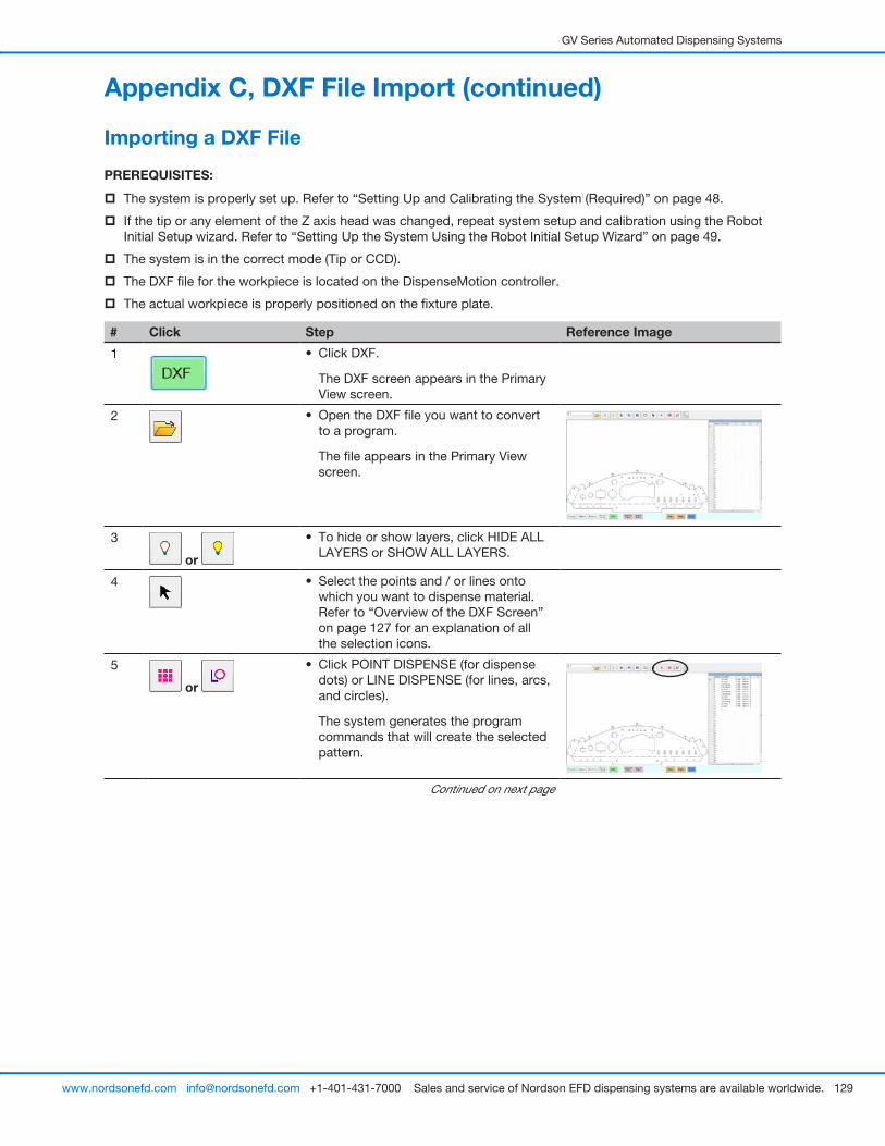
GV Series Automated Dispensing Systems
129www.nordsonefd.com [email protected] +1-401-431-7000 Sales and service of Nordson EFD dispensing systems are available worldwide.
Importing a DXF File
PREREQUISITES:
� The system is properly set up. Refer to “Setting Up and Calibrating the System (Required)” on page 48.
� If the tip or any element of the Z axis head was changed, repeat system setup and calibration using the Robot Initial Setup wizard. Refer to “Setting Up the System Using the Robot Initial Setup Wizard” on page 49.
� The system is in the correct mode (Tip or CCD).
� The DXF file for the workpiece is located on the DispenseMotion controller.
� The actual workpiece is properly positioned on the fixture plate.
# Click Step Reference Image
1 • Click DXF.
The DXF screen appears in the Primary View screen.
2 • Open the DXF file you want to convert to a program.
The file appears in the Primary View screen.
3
or
• To hide or show layers, click HIDE ALL LAYERS or SHOW ALL LAYERS.
4 • Select the points and / or lines onto which you want to dispense material. Refer to “Overview of the DXF Screen” on page 127 for an explanation of all the selection icons.
5
or
• Click POINT DISPENSE (for dispense dots) or LINE DISPENSE (for lines, arcs, and circles).
The system generates the program commands that will create the selected pattern.
Continued on next page
Appendix C, DXF File Import (continued)
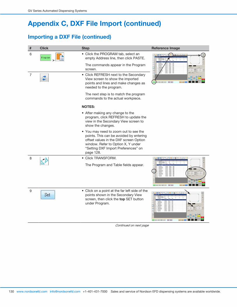
GV Series Automated Dispensing Systems
130 www.nordsonefd.com [email protected] +1-401-431-7000 Sales and service of Nordson EFD dispensing systems are available worldwide.
# Click Step Reference Image
6
>
• Click the PROGRAM tab, select an empty Address line, then click PASTE.
The commands appear in the Program screen.
7 • Click REFRESH next to the Secondary View screen to show the imported points and lines and make changes as needed to the program.
The next step is to match the program commands to the actual workpiece.
NOTES:
• After making any change to the program, click REFRESH to update the view in the Secondary View screen to show the changes.
• You may need to zoom out to see the points. This can be avoided by entering offset values in the DXF screen Option window. Refer to Option X, Y under “Setting DXF Import Preferences” on page 128.
8 • Click TRANSFORM.
The Program and Table fields appear.
9 • Click on a point at the far left side of the points shown in the Secondary View screen, then click the top SET button under Program.
Continued on next page
Importing a DXF File (continued)
Appendix C, DXF File Import (continued)
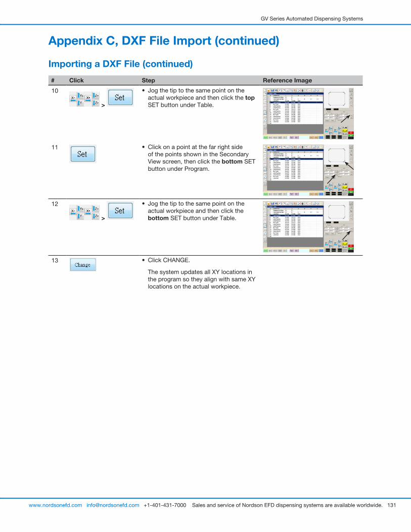
GV Series Automated Dispensing Systems
131www.nordsonefd.com [email protected] +1-401-431-7000 Sales and service of Nordson EFD dispensing systems are available worldwide.
# Click Step Reference Image
10
>
• Jog the tip to the same point on the actual workpiece and then click the top SET button under Table.
11 • Click on a point at the far right side of the points shown in the Secondary View screen, then click the bottom SET button under Program.
12
>
• Jog the tip to the same point on the actual workpiece and then click the bottom SET button under Table.
13 • Click CHANGE.
The system updates all XY locations in the program so they align with same XY locations on the actual workpiece.
Importing a DXF File (continued)
Appendix C, DXF File Import (continued)
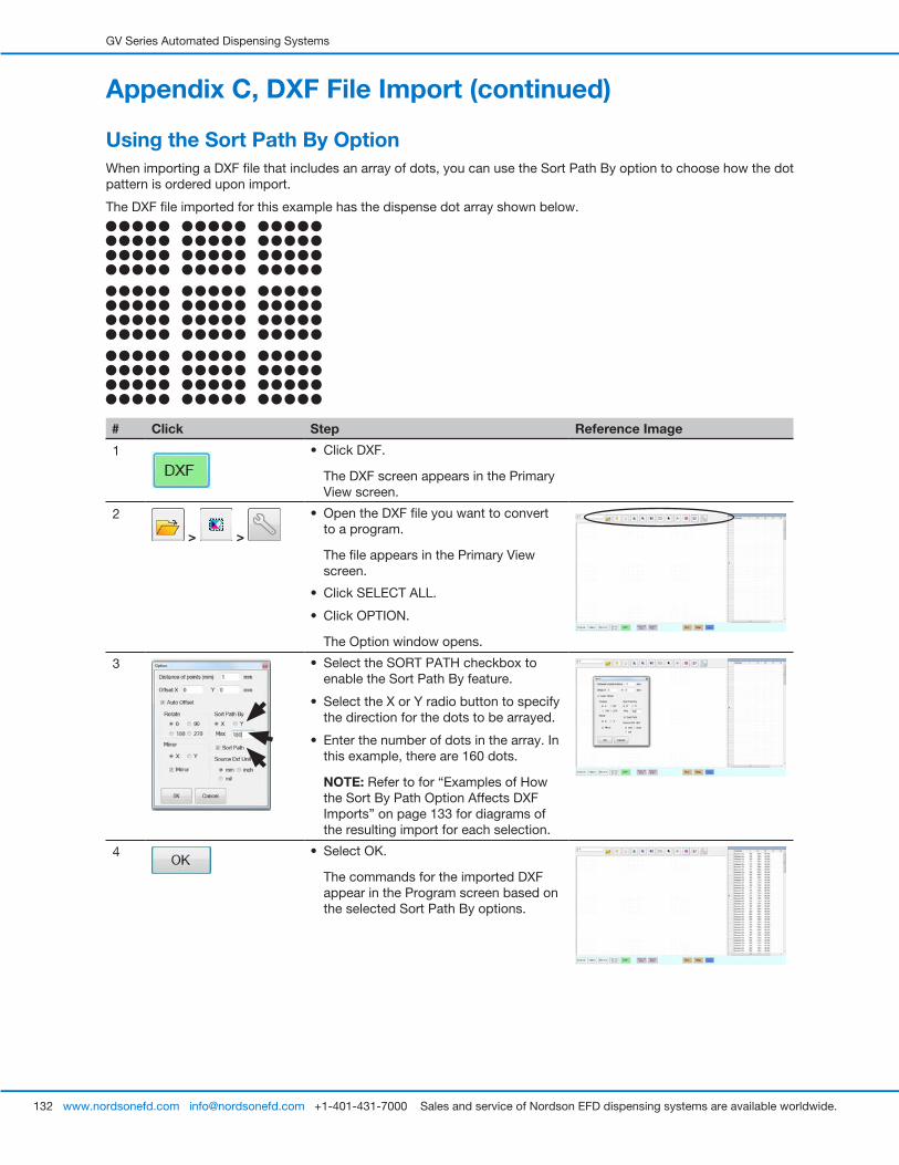
GV Series Automated Dispensing Systems
132 www.nordsonefd.com [email protected] +1-401-431-7000 Sales and service of Nordson EFD dispensing systems are available worldwide.
Using the Sort Path By OptionWhen importing a DXF file that includes an array of dots, you can use the Sort Path By option to choose how the dot pattern is ordered upon import.
The DXF file imported for this example has the dispense dot array shown below.
# Click Step Reference Image
1 • Click DXF.
The DXF screen appears in the Primary View screen.
2
> >
• Open the DXF file you want to convert to a program.
The file appears in the Primary View screen.
• Click SELECT ALL.
• Click OPTION.
The Option window opens.
3 • Select the SORT PATH checkbox to enable the Sort Path By feature.
• Select the X or Y radio button to specify the direction for the dots to be arrayed.
• Enter the number of dots in the array. In this example, there are 160 dots.
NOTE: Refer to for “Examples of How the Sort By Path Option Affects DXF Imports” on page 133 for diagrams of the resulting import for each selection.
4 • Select OK.
The commands for the imported DXF appear in the Program screen based on the selected Sort Path By options.
Appendix C, DXF File Import (continued)
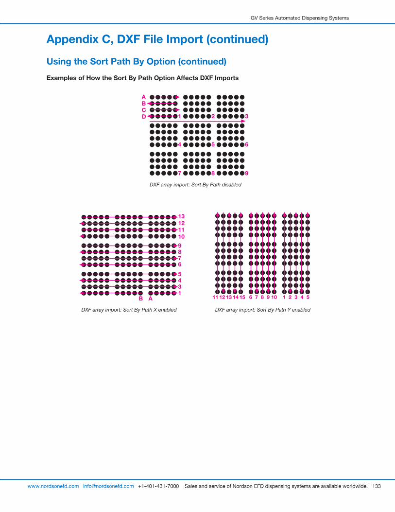
GV Series Automated Dispensing Systems
133www.nordsonefd.com [email protected] +1-401-431-7000 Sales and service of Nordson EFD dispensing systems are available worldwide.
Using the Sort Path By Option (continued)
Appendix C, DXF File Import (continued)
Examples of How the Sort By Path Option Affects DXF Imports
DXF array import: Sort By Path disabled
ABCD 1 2 3
4 5 6
7 8 9
DXF array import: Sort By Path X enabled
A1345
6789
10111213
B
DXF array import: Sort By Path Y enabled
21 3 4 576 8 9 1011 12 13 14 15
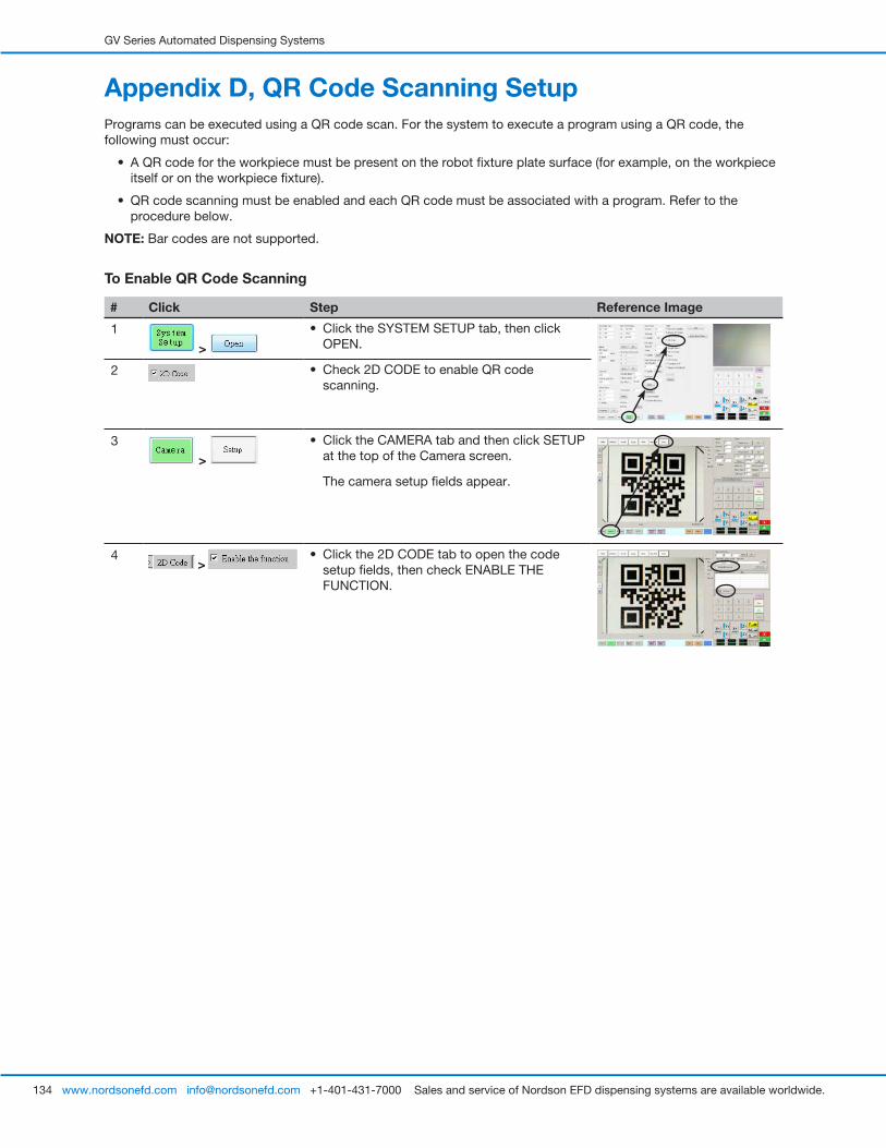
GV Series Automated Dispensing Systems
134 www.nordsonefd.com [email protected] +1-401-431-7000 Sales and service of Nordson EFD dispensing systems are available worldwide.
Appendix D, QR Code Scanning SetupPrograms can be executed using a QR code scan. For the system to execute a program using a QR code, the following must occur:
• A QR code for the workpiece must be present on the robot fixture plate surface (for example, on the workpiece itself or on the workpiece fixture).
• QR code scanning must be enabled and each QR code must be associated with a program. Refer to the procedure below.
NOTE: Bar codes are not supported.
To Enable QR Code Scanning
# Click Step Reference Image
1
>
• Click the SYSTEM SETUP tab, then click OPEN.
2 • Check 2D CODE to enable QR code scanning.
3
>
• Click the CAMERA tab and then click SETUP at the top of the Camera screen.
The camera setup fields appear.
4 >
• Click the 2D CODE tab to open the code setup fields, then check ENABLE THE FUNCTION.
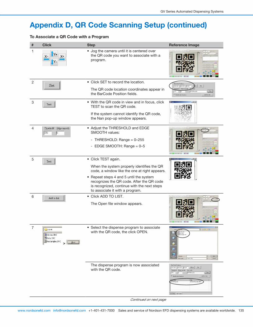
GV Series Automated Dispensing Systems
135www.nordsonefd.com [email protected] +1-401-431-7000 Sales and service of Nordson EFD dispensing systems are available worldwide.
Appendix D, QR Code Scanning Setup (continued)To Associate a QR Code with a Program
# Click Step Reference Image
1 • Jog the camera until it is centered over the QR code you want to associate with a program.
2 • Click SET to record the location.
The QR code location coordinates appear in the BarCode Position fields.
3 • With the QR code in view and in focus, click TEST to scan the QR code.
If the system cannot identify the QR code, the Nan pop-up window appears.
4 • Adjust the THRESHOLD and EDGE SMOOTH values:
- THRESHOLD: Range = 0–255
- EDGE SMOOTH: Range = 0–5
5 • Click TEST again.
When the system properly identifies the QR code, a window like the one at right appears.
• Repeat steps 4 and 5 until the system recognizes the QR code. After the QR code is recognized, continue with the next steps to associate it with a program.
6 • Click ADD TO LIST.
The Open file window appears.
7
>
• Select the dispense program to associate with the QR code, the click OPEN.
The dispense program is now associated with the QR code.
Continued on next page

GV Series Automated Dispensing Systems
136 www.nordsonefd.com [email protected] +1-401-431-7000 Sales and service of Nordson EFD dispensing systems are available worldwide.
# Click Step Reference Image
8 • Continue to add additional QR codes as needed.
• To remove a QR code, right-click on the QR code and then click DELETE.
9
>
• Return to PROGRAM screen and then click RUN to test the program.
The system finds the QR code, scans it, opens the associated program, and executes the program.
Refer to the screen captures.
The system is now set up for QR code scanning. Refer to “Running a Program by Scanning a QR Code” on page 88 for an operating procedure.
Appendix D, QR Code Scanning Setup (continued)
To Associate a QR Code with a Program (continued)
1. Clicking PROGRAM and then RUN to test the program. 2. The system moves to the QR code and scans it.
The system opens the program and executes it.
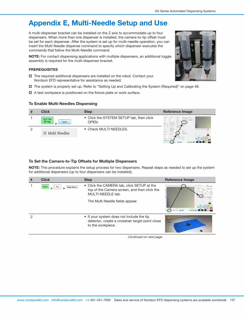
GV Series Automated Dispensing Systems
137www.nordsonefd.com [email protected] +1-401-431-7000 Sales and service of Nordson EFD dispensing systems are available worldwide.
Appendix E, Multi-Needle Setup and UseA multi-dispenser bracket can be installed on the Z axis to accommodate up to four dispensers. When more than one dispenser is installed, the camera-to-tip offset must be set for each dispenser. After the system is set up for multi-needle operation, you can insert the Multi Needle dispense command to specify which dispenser executes the commands that follow the Multi-Needle command.
NOTE: For contact dispensing applications with multiple dispensers, an additional toggle assembly is required for the multi-dispenser bracket.
PREREQUISITES
� The required additional dispensers are installed on the robot. Contact your Nordson EFD representative for assistance as needed.
� The system is properly set up. Refer to “Setting Up and Calibrating the System (Required)” on page 48.
� A test workpiece is positioned on the fixture plate or work surface.
To Enable Multi-Needles Dispensing
# Click Step Reference Image
1
>
• Click the SYSTEM SETUP tab, then click OPEN.
2 • Check MULTI NEEDLES.
To Set the Camera-to-Tip Offsets for Multiple Dispensers
NOTE: This procedure explains the setup process for two dispensers. Repeat steps as needed to set up the system for additional dispensers (up to four dispensers can be installed).
# Click Step Reference Image
1 > >
• Click the CAMERA tab, click SETUP at the top of the Camera screen, and then click the MULTI-NEEDLE tab.
The Multi Needle fields appear.
2 • If your system does not include the tip detector, create a crosshair target point close to the workpiece.
Continued on next page
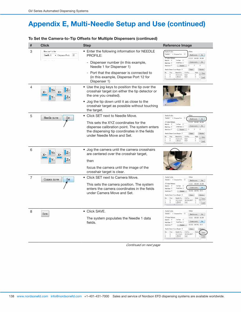
GV Series Automated Dispensing Systems
138 www.nordsonefd.com [email protected] +1-401-431-7000 Sales and service of Nordson EFD dispensing systems are available worldwide.
# Click Step Reference Image
3 • Enter the following information for NEEDLE PROFILE:
- Dispenser number (in this example, Needle 1 for Dispenser 1)
- Port that the dispenser is connected to (in this example, Dispense Port 12 for Dispenser 1)
4 • Use the jog keys to position the tip over the crosshair target (on either the tip detector or the one you created).
• Jog the tip down until it as close to the crosshair target as possible without touching the target.
5 • Click SET next to Needle Move.
This sets the XYZ coordinates for the dispense calibration point. The system enters the dispensing tip coordinates in the fields under Needle Move and Set.
6 • Jog the camera until the camera crosshairs are centered over the crosshair target,
then
focus the camera until the image of the crosshair target is clear.
7 • Click SET next to Camera Move.
This sets the camera position. The system enters the camera coordinates in the fields under Camera Move and Set.
8 • Click SAVE.
The system populates the Needle 1 data fields.
Continued on next page
Appendix E, Multi-Needle Setup and Use (continued)
To Set the Camera-to-Tip Offsets for Multiple Dispensers (continued)
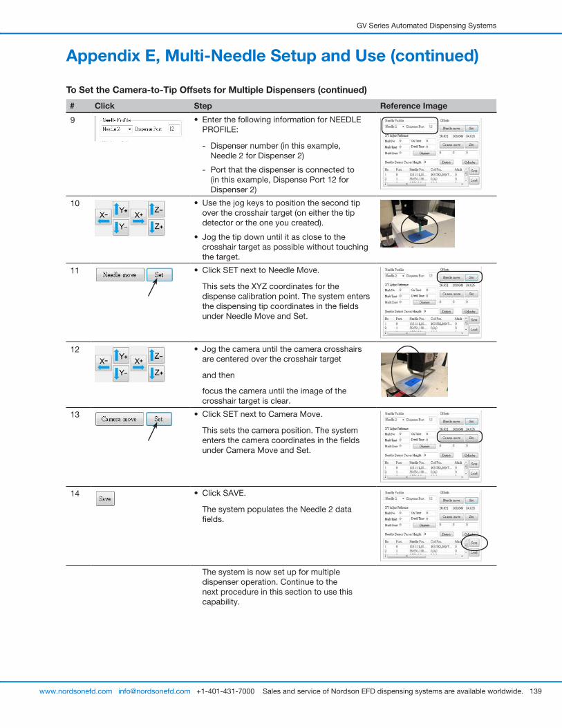
GV Series Automated Dispensing Systems
139www.nordsonefd.com [email protected] +1-401-431-7000 Sales and service of Nordson EFD dispensing systems are available worldwide.
Appendix E, Multi-Needle Setup and Use (continued)
To Set the Camera-to-Tip Offsets for Multiple Dispensers (continued)
# Click Step Reference Image
9 • Enter the following information for NEEDLE PROFILE:
- Dispenser number (in this example, Needle 2 for Dispenser 2)
- Port that the dispenser is connected to (in this example, Dispense Port 12 for Dispenser 2)
10 • Use the jog keys to position the second tip over the crosshair target (on either the tip detector or the one you created).
• Jog the tip down until it as close to the crosshair target as possible without touching the target.
11 • Click SET next to Needle Move.
This sets the XYZ coordinates for the dispense calibration point. The system enters the dispensing tip coordinates in the fields under Needle Move and Set.
12 • Jog the camera until the camera crosshairs are centered over the crosshair target
and then
focus the camera until the image of the crosshair target is clear.
13 • Click SET next to Camera Move.
This sets the camera position. The system enters the camera coordinates in the fields under Camera Move and Set.
14 • Click SAVE.
The system populates the Needle 2 data fields.
The system is now set up for multiple dispenser operation. Continue to the next procedure in this section to use this capability.
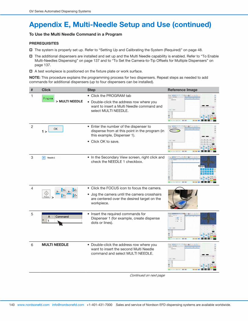
GV Series Automated Dispensing Systems
140 www.nordsonefd.com [email protected] +1-401-431-7000 Sales and service of Nordson EFD dispensing systems are available worldwide.
Appendix E, Multi-Needle Setup and Use (continued)To Use the Multi Needle Command in a Program
PREREQUISITES
� The system is properly set up. Refer to “Setting Up and Calibrating the System (Required)” on page 48.
� The additional dispensers are installed and set up and the Multi Needle capability is enabled. Refer to “To Enable Multi-Needles Dispensing” on page 137 and to “To Set the Camera-to-Tip Offsets for Multiple Dispensers” on page 137.
� A test workpiece is positioned on the fixture plate or work surface.
NOTE: This procedure explains the programming process for two dispensers. Repeat steps as needed to add commands for additional dispensers (up to four dispensers can be installed).
# Click Step Reference Image
1
> MULTI NEEDLE
• Click the PROGRAM tab
• Double-click the address row where you want to insert a Multi Needle command and select MULTI NEEDLE.
2 1 >
• Enter the number of the dispenser to dispense from at this point in the program (in this example, Dispenser 1).
• Click OK to save.
3 • In the Secondary View screen, right click and check the NEEDLE 1 checkbox.
4
>
• Click the FOCUS icon to focus the camera.
• Jog the camera until the camera crosshairs are centered over the desired target on the workpiece.
5 • Insert the required commands for Dispenser 1 (for example, create dispense dots or lines).
6 MULTI NEEDLE • Double-click the address row where you want to insert the second Multi Needle command and select MULTI NEEDLE.
Continued on next page
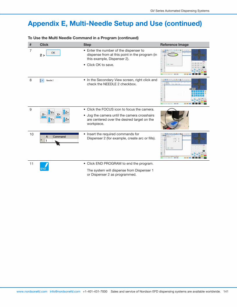
GV Series Automated Dispensing Systems
141www.nordsonefd.com [email protected] +1-401-431-7000 Sales and service of Nordson EFD dispensing systems are available worldwide.
# Click Step Reference Image
7 2 >
• Enter the number of the dispenser to dispense from at this point in the program (in this example, Dispenser 2).
• Click OK to save.
8 • In the Secondary View screen, right click and check the NEEDLE 2 checkbox.
9 • Click the FOCUS icon to focus the camera.
• Jog the camera until the camera crosshairs are centered over the desired target on the workpiece.
10 • Insert the required commands for Dispenser 2 (for example, create arc or fills).
11 • Click END PROGRAM to end the program.
The system will dispense from Dispenser 1 or Dispenser 2 as programmed.
Appendix E, Multi-Needle Setup and Use (continued)
To Use the Multi Needle Command in a Program (continued)
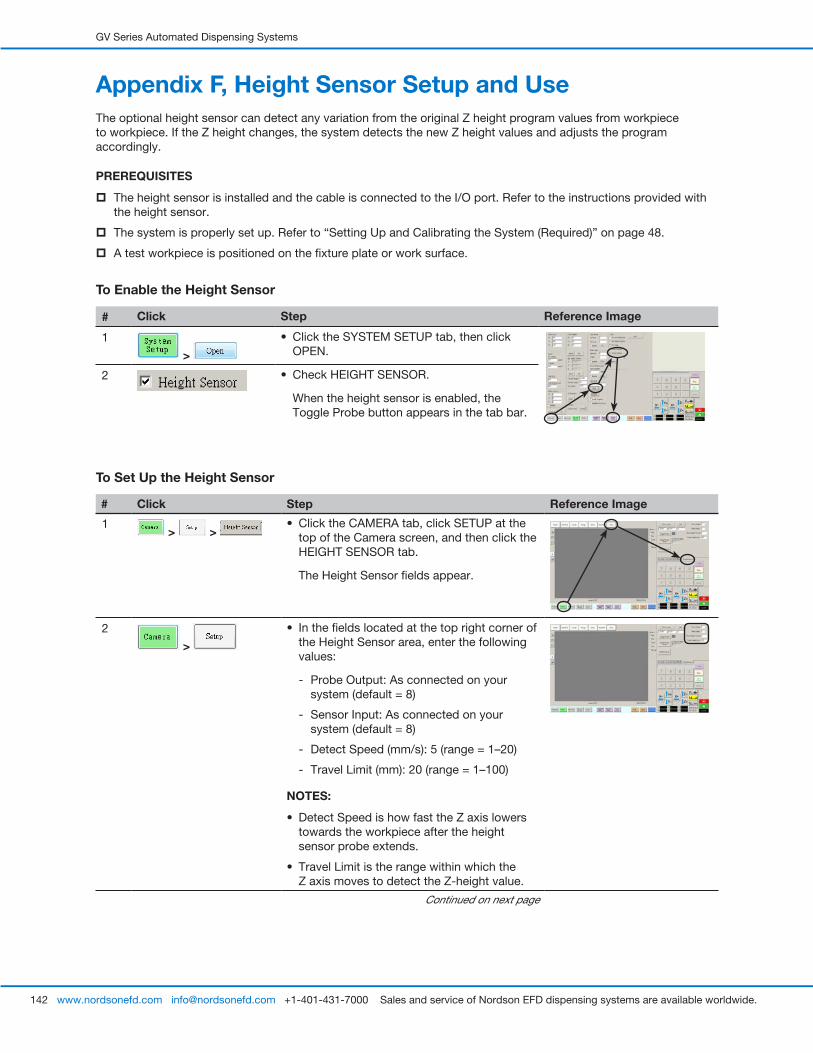
GV Series Automated Dispensing Systems
142 www.nordsonefd.com [email protected] +1-401-431-7000 Sales and service of Nordson EFD dispensing systems are available worldwide.
To Set Up the Height Sensor
# Click Step Reference Image
1 > >
• Click the CAMERA tab, click SETUP at the top of the Camera screen, and then click the HEIGHT SENSOR tab.
The Height Sensor fields appear.
2
>
• In the fields located at the top right corner of the Height Sensor area, enter the following values:
- Probe Output: As connected on your system (default = 8)
- Sensor Input: As connected on your system (default = 8)
- Detect Speed (mm/s): 5 (range = 1–20)
- Travel Limit (mm): 20 (range = 1–100)
NOTES:
• Detect Speed is how fast the Z axis lowers towards the workpiece after the height sensor probe extends.
• Travel Limit is the range within which the Z axis moves to detect the Z-height value.
Continued on next page
Appendix F, Height Sensor Setup and UseThe optional height sensor can detect any variation from the original Z height program values from workpiece to workpiece. If the Z height changes, the system detects the new Z height values and adjusts the program accordingly.
PREREQUISITES
� The height sensor is installed and the cable is connected to the I/O port. Refer to the instructions provided with the height sensor.
� The system is properly set up. Refer to “Setting Up and Calibrating the System (Required)” on page 48.
� A test workpiece is positioned on the fixture plate or work surface.
To Enable the Height Sensor
# Click Step Reference Image
1
>
• Click the SYSTEM SETUP tab, then click OPEN.
2 • Check HEIGHT SENSOR.
When the height sensor is enabled, the Toggle Probe button appears in the tab bar.
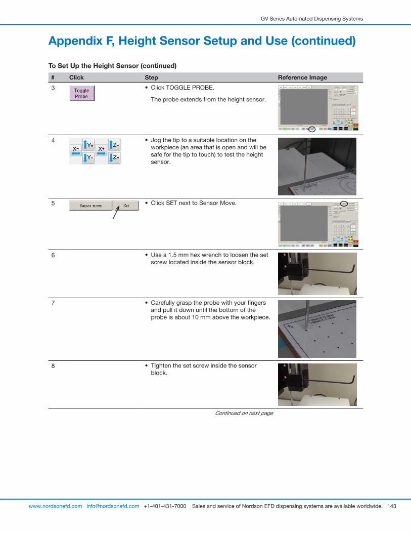
GV Series Automated Dispensing Systems
143www.nordsonefd.com [email protected] +1-401-431-7000 Sales and service of Nordson EFD dispensing systems are available worldwide.
# Click Step Reference Image
3 • Click TOGGLE PROBE.
The probe extends from the height sensor.
4 • Jog the tip to a suitable location on the workpiece (an area that is open and will be safe for the tip to touch) to test the height sensor.
5 • Click SET next to Sensor Move.
6 • Use a 1.5 mm hex wrench to loosen the set screw located inside the sensor block.
7 • Carefully grasp the probe with your fingers and pull it down until the bottom of the probe is about 10 mm above the workpiece.
8 • Tighten the set screw inside the sensor block.
Continued on next page
Appendix F, Height Sensor Setup and Use (continued)
To Set Up the Height Sensor (continued)
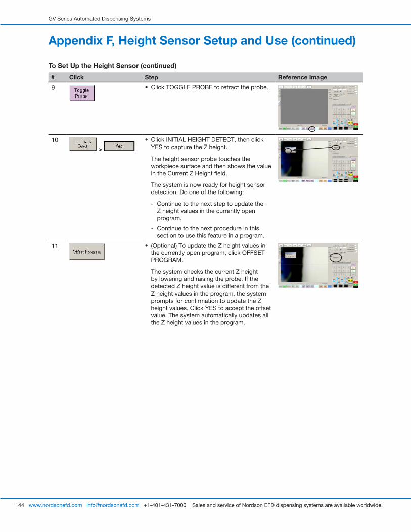
GV Series Automated Dispensing Systems
144 www.nordsonefd.com [email protected] +1-401-431-7000 Sales and service of Nordson EFD dispensing systems are available worldwide.
# Click Step Reference Image
9 • Click TOGGLE PROBE to retract the probe.
10
>
• Click INITIAL HEIGHT DETECT, then click YES to capture the Z height.
The height sensor probe touches the workpiece surface and then shows the value in the Current Z Height field.
The system is now ready for height sensor detection. Do one of the following:
- Continue to the next step to update the Z height values in the currently open program.
- Continue to the next procedure in this section to use this feature in a program.
11 • (Optional) To update the Z height values in the currently open program, click OFFSET PROGRAM.
The system checks the current Z height by lowering and raising the probe. If the detected Z height value is different from the Z height values in the program, the system prompts for confirmation to update the Z height values. Click YES to accept the offset value. The system automatically updates all the Z height values in the program.
Appendix F, Height Sensor Setup and Use (continued)
To Set Up the Height Sensor (continued)

GV Series Automated Dispensing Systems
145www.nordsonefd.com [email protected] +1-401-431-7000 Sales and service of Nordson EFD dispensing systems are available worldwide.
Appendix F, Height Sensor Setup and Use (continued)To Use the Height Sensor Capability
PREREQUISITES
� The system is properly set up. Refer to “Setting Up and Calibrating the System (Required)” on page 48.
� The height sensor is installed, enabled, and set up. Refer to “To Enable the Height Sensor” on page 142 and to “To Set Up the Height Sensor” on page 142.
� The program you want to edit using the height sensor capability is open.
# Click Step Reference Image
1 • Click TOGGLE PROBE.
The probe extends from the height sensor.
2 • Jog to the location where the system should check the height for each workpiece.
• Use the Z jog keys to lower the probe to approximately 10 mm (0.4") above the target location on the workpiece.
3 HEIGHT SENSOR > • Double-click the address row where
you want to insert a Height Sensor command and then select HEIGHT SENSOR from the drop-down menu.
• Click OK to accept the XYZ values.
4 • Click TOGGLE PROBE to retract the probe.
The system will now check the workpiece height each time the programs runs.
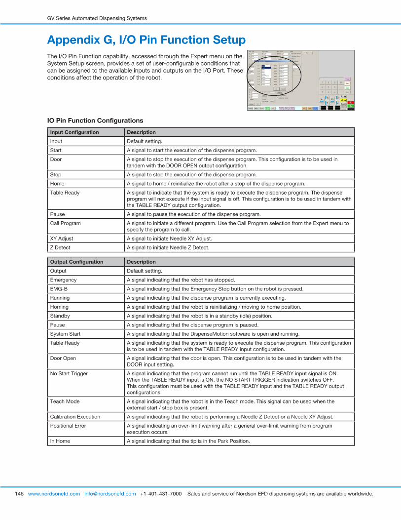
GV Series Automated Dispensing Systems
146 www.nordsonefd.com [email protected] +1-401-431-7000 Sales and service of Nordson EFD dispensing systems are available worldwide.
IO Pin Function Configurations
Input Configuration Description
Input Default setting.
Start A signal to start the execution of the dispense program.
Door A signal to stop the execution of the dispense program. This configuration is to be used in tandem with the DOOR OPEN output configuration.
Stop A signal to stop the execution of the dispense program.
Home A signal to home / reinitialize the robot after a stop of the dispense program.
Table Ready A signal to indicate that the system is ready to execute the dispense program. The dispense program will not execute if the input signal is off. This configuration is to be used in tandem with the TABLE READY output configuration.
Pause A signal to pause the execution of the dispense program.
Call Program A signal to initiate a different program. Use the Call Program selection from the Expert menu to specify the program to call.
XY Adjust A signal to initiate Needle XY Adjust.
Z Detect A signal to initiate Needle Z Detect.
Output Configuration Description
Output Default setting.
Emergency A signal indicating that the robot has stopped.
EMG-B A signal indicating that the Emergency Stop button on the robot is pressed.
Running A signal indicating that the dispense program is currently executing.
Homing A signal indicating that the robot is reinitializing / moving to home position.
Standby A signal indicating that the robot is in a standby (idle) position.
Pause A signal indicating that the dispense program is paused.
System Start A signal indicating that the DispenseMotion software is open and running.
Table Ready A signal indicating that the system is ready to execute the dispense program. This configuration is to be used in tandem with the TABLE READY input configuration.
Door Open A signal indicating that the door is open. This configuration is to be used in tandem with the DOOR input setting.
No Start Trigger A signal indicating that the program cannot run until the TABLE READY input signal is ON. When the TABLE READY input is ON, the NO START TRIGGER indication switches OFF. This configuration must be used with the TABLE READY input and the TABLE READY output configurations.
Teach Mode A signal indicating that the robot is in the Teach mode. This signal can be used when the external start / stop box is present.
Calibration Execution A signal indicating that the robot is performing a Needle Z Detect or a Needle XY Adjust.
Positional Error A signal indicating an over-limit warning after a general over-limit warning from program execution occurs.
In Home A signal indicating that the tip is in the Park Position.
Appendix G, I/O Pin Function SetupThe I/O Pin Function capability, accessed through the Expert menu on the System Setup screen, provides a set of user-configurable conditions that can be assigned to the available inputs and outputs on the I/O Port. These conditions affect the operation of the robot.

GV Series Automated Dispensing Systems
147www.nordsonefd.com [email protected] +1-401-431-7000 Sales and service of Nordson EFD dispensing systems are available worldwide.
To Reconfigure Inputs / Outputs
PREREQUISITES
� The system is properly set up. Refer to “Setting Up and Calibrating the System (Required)” on page 48.
# Click Step Reference Image
1 • Connect the signal wiring to the I/O Port on the back of the GV operation box.
2
> >
• Click SYSTEM SETUP > OPEN > EXPERT.
3 11111111 >
• Enter 11111111, then click OK.
4 • Click IO PIN FUNCTION.
5
>
• Click the input or output to configure, then select the configuration from the drop-down menu. Refer to “IO Pin Function Configurations” on page 146 for a description of the configuration selections.
• Click OK.
Appendix G, I/O Pin Function Setup (continued)
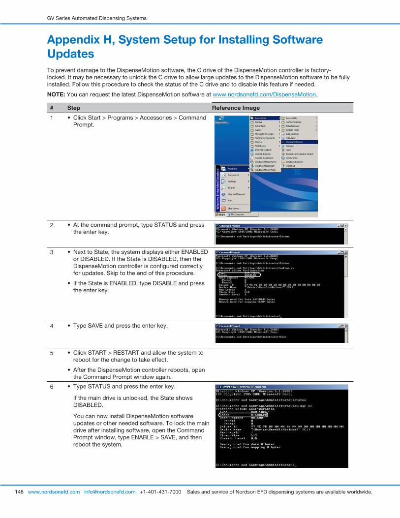
GV Series Automated Dispensing Systems
148 www.nordsonefd.com [email protected] +1-401-431-7000 Sales and service of Nordson EFD dispensing systems are available worldwide.
Appendix H, System Setup for Installing Software UpdatesTo prevent damage to the DispenseMotion software, the C drive of the DispenseMotion controller is factory-locked. It may be necessary to unlock the C drive to allow large updates to the DispenseMotion software to be fully installed. Follow this procedure to check the status of the C drive and to disable this feature if needed.
NOTE: You can request the latest DispenseMotion software at www.nordsonefd.com/DispenseMotion.
# Step Reference Image
1 • Click Start > Programs > Accessories > Command Prompt.
2 • At the command prompt, type STATUS and press the enter key.
3 • Next to State, the system displays either ENABLED or DISABLED. If the State is DISABLED, then the DispenseMotion controller is configured correctly for updates. Skip to the end of this procedure.
• If the State is ENABLED, type DISABLE and press the enter key.
4 • Type SAVE and press the enter key.
5 • Click START > RESTART and allow the system to reboot for the change to take effect.
• After the DispenseMotion controller reboots, open the Command Prompt window again.
6 • Type STATUS and press the enter key.
If the main drive is unlocked, the State shows DISABLED.
You can now install DispenseMotion software updates or other needed software. To lock the main drive after installing software, open the Command Prompt window, type ENABLE > SAVE, and then reboot the system.
GV Series Automated Dispensing Systems
149www.nordsonefd.com [email protected] +1-401-431-7000 Sales and service of Nordson EFD dispensing systems are available worldwide.
Notes
For Nordson EFD sales and service in over 40 countries, contact Nordson EFD or go to www.nordsonefd.com.
Global 800-556-3484; +1-401-431-7000 [email protected]
Europe 00800 7001 7001 [email protected]
Asia China: +86 (21) 3866 9006; [email protected] India: +91 80 4021 3600; [email protected] Japan: +81 03 5762 2760; [email protected] Korea: +82-31-736-8321; [email protected] SEAsia: +65 6796 9522; [email protected]
The Wave Design is a trademark of Nordson Corporation. ©2021 Nordson Corporation 7363625 v051121
NORDSON EFD ONE YEAR LIMITED WARRANTY
This Nordson EFD product is warranted for one year [two years, five years] from the date of purchase to be free from defects in material and workmanship (but not against damage caused by misuse, abrasion, corrosion, negligence, accident, faulty installation, or by dispensing material incompatible with equipment) when the equipment is installed and operated in accordance with factory recommendations and instructions.
Nordson EFD will repair or replace free of charge any defective part upon authorized return of the part prepaid to our factory during the warranty period. The only exceptions are those parts which normally wear and must be replaced routinely, such as, but not limited to, valve diaphragms, seals, valve heads, needles, and nozzles.
In no event shall any liability or obligation of Nordson EFD arising from this warranty exceed the purchase price of the equipment.
Before operation, the user shall determine the suitability of this product for its intended use, and the user assumes all risk and liability whatsoever in connection therewith. Nordson EFD makes no warranty of merchantability or fitness for a particular purpose. In no event shall Nordson EFD be liable for incidental or consequential damages.
This warranty is valid only when oil-free, clean, dry, filtered air is used, where applicable.


