H4E-0050 Portable Gas Monitor GX-8000 User Maintenance Manual (H4-0050) This gas monitor must be maintained in a normal state at all times to prevent accidents due to gas leaks. Daily and regular maintenance is required to keep the gas monitor in a normal state. Neglecting maintenance will result in failures and false alarms. The specified maintenance procedures must be performed for the sake of maintenance of a normal state. Also, maintenance by the manufacturer (comprehensive maintenance) should be performed in addition to these maintenance specified in this manual. This manual complements the Operating Manual (main manual) . Be sure to read and understand thoroughly both this manual and the Operating Manual including precautions to ensure proper use of this gas monitor. Need of Maintenance and Servicing
Transcript
H4E-0050
Portable Gas Monitor
GX-8000
User Maintenance Manual
(H4-0050)
This gas monitor must be maintained in a normal state at all times to prevent accidents due to gas leaks. Daily and regular maintenance is required to keep the gas monitor in a normal state. Neglecting maintenance will result in failures and false alarms. The specified maintenance procedures must be performed for the sake of maintenance of a normal state. Also, maintenance by the manufacturer (comprehensive maintenance) should be performed in addition to these maintenance specified in this manual. This manual complements the Operating Manual (main manual). Be sure to read and understand thoroughly both this manual and the Operating Manual including precautions to ensure proper use of this gas monitor.
Need of Maintenance and Servicing
1 Maintenance Intervals and Items
GX-8000 - 2 -
1
Maintenance Intervals and Items
• Daily maintenance: Perform maintenance before beginning to work. • Monthly maintenance: Perform alarm test once a month. • Regular maintenance: Perform a maintenance once or more for every six months to maintain the
performance as a safety unit.
Maintenance item
Maintenance content Daily maintenance
Monthly maintenance
Regular maintenance
Battery level check Check that the battery level is sufficient.
Concentration display check
Make the gas monitor draw in fresh air. Check that the concentration display value is zero (or 20.9 vol% on the oxygen deficiency meter). When the reading is incorrect, perform the zero adjustment (fresh air adjustment) after ensuring that no other gases exist around it.
Flow rate check See the flow rate indicator to check for abnormalities.
Filter check Check the dust filter for dust or clogging. Alarm test Check the alarm lamp and buzzer for normal
operation by using the alarm test function.
Span adjustment Perform the span adjustment by using the calibration gas.
Gas alarm check Check the gas alarm by using the calibration gas.
2 Regular Maintenance Mode
- 3 - GX-8000
2
Regular Maintenance Mode Regular maintenance mode is an operation (adjustment) mode in which span adjustment and setup such as change of alarm setpoints can be performed. The regular maintenance mode comes in two types: Calibration and maintenance modes. To enter the calibration mode, press the DISPLAY switch with the switch pressed in the detection mode and release them when the buzzer sounds. To enter the maintenance mode, press the POWER switch with the and
switches pressed at power-on and release them when the buzzer sounds. The maintenance mode is password-protected. The input of a password is needed in the beginning.
WARNING After the adjustment is completed, do not forget to return to the detection mode. (If the gas monitor remains in the regular maintenance mode, it does not automatically return to the detection mode.)
2 Regular Maintenance Mode
GX-8000 - 4 -
The regular maintenance mode has the menus shown below.
Mode Item LCD display Details Fresh air adjustment AIR CAL Perform the fresh air adjustment. * Zero adjustment for high-concentration combustible gases
VOLZ.CAL Perform the zero adjustment for high-concentration combustible gases.
Simultaneous span adjustment for all channels
AUTO CAL Perform the span adjustment simultaneously for all channels.
**
Span adjustment for each channel
ONE CAL Perform the span adjustment for each channel.
**
Bump test BUMP Perform the bump test. **
Calibration mode
Exit calibration mode NORMAL Exit the calibration mode and return to the detection mode.
**
Date/time setting DATE Set the date and time. Fresh air adjustment AIR CAL Perform the fresh air adjustment. * Zero adjustment for high-concentration combustible gases
VOL Z.CAL Perform the zero adjustment for high-concentration combustible gases.
Simultaneous span adjustment for all channels
AUTO CAL Perform the span adjustment simultaneously for all channels.
Span adjustment for each channel
ONE CAL Perform the span adjustment for each channel.
Bump test BUMP Perform the bump test. *** Alarm setting ALARM-P Change the alarm setpoint value. Bump test setting BUMP-SET Set the bump test. *** Beep setting BEEP SET Set the confirmation beep
operation. ***
Maintenance mode
Exit maintenance mode START Exit the maintenance mode and enter the detection mode.
* mark indicates items that can be operated (adjusted) in other modes such as [Detection mode] than the regular maintenance mode. Note that operation can be performed in any mode.
** mark indicates the menus in the calibration modes available in the overseas specification: AUTO CAL, ONE CAL, BUMP, and NORMAL.
*** mark indicates the items not available in the Japanese specifications. NOTE If any mode that is not described in this manual or Operating Manual (main manual) (any mode but the regular maintenance mode) is entered by mistake, turn off the power once and try again.
2 Regular Maintenance Mode
- 5 - GX-8000
<<Calibration Mode>>
Fresh air adjustment => P16
In the detection mode, keep pressed and press the DISPLAY switch. When the buzzer beeps, release the switches.
Calibration mode AIR CAL Perform the fresh air adjustment.
Zero adjustment for high- concentration combustible gases => P20
VOLZ.CAL Perform the zero adjustment for high-concentration combustible gases.
Simultaneous span adjustment for all channels => P18
AUTO CAL Perform the span adjustment simultaneously for all channels. (Set the span gas concentration in advance and make adjustment at once.)
Span adjustmentfor each channel => P19
ONE CAL Perform the span adjustment for each channel. (While gas is supplied, perform span adjustment using UP/DOWN.)
Bump test => P6
BUMP Perform the bump test.
Detection modeNORMAL Exit the calibration mode.
2 Regular Maintenance Mode
GX-8000 - 6 -
<Bump Test "BUMP"> Required equipment/material • Bump test gas (collected in a gas sampling bag) Connection Connect the equipment as shown below to perform the bump test.
Gas
sampling bag
Gas sampling probe (with a tube)
GX-8000 main unit
GAS IN
GAS OUT (Open)
WARNING About the bump test gas The bump test gas is a hazardous gas (toxic, oxygen deficient, etc.). Handle the gas and related jigs and tools with due care (e.g., the gas must not be inhaled or the gas sampling bag must not have any hole). About the place for span adjustment • Perform span adjustment where no silicon, organic solvent, spray can gases, etc. are used. • Perform span adjustment indoors at normal temperature without remarkable fluctuation (within ±5°C). • Perform span adjustment in an exhaust booth.
CAUTION The GAS OUT side of the pipe must be left open without any pipe connected. A supplied gas must be discharged to a safe place.
2 Regular Maintenance Mode
- 7 - GX-8000
BUMP Press the ENTER switch.
The bump test gas concentration is displayed.The concentration of the prepared test gas must be consistent with the displayed test gas concentration. To change the test gas concentration value, change the value in span adjustment menu. The test gas concentration is set to the same value as the span gas concentration. Simultaneous span adjustment for all channels => P18
Supply the test gas.
NOTE Only on TYPE-A and TYPE-E, every time the or switch is pressed, the concentration of the span gas for high-concentration combustible gases is displayed alternately.
Go to (1) if all the channels are Pass in about 30 seconds. Go to (2) if any of the channels is Fail.
(1)
Supply the test gas and press ENTER. BUMP and APPLY are displayed alternately, and the countdown is started.
<If all the channels are Pass> The result is displayed in about 30 seconds. Stop supplying the gas. The results and values are displayed alternately every time the or switch is pressed. P: Pass, F: Fail After checking the result, press ENTER. The gas monitor returns to the calibration mode menu.
Return to BUMP. Stop supplying the test gas.
2 Regular Maintenance Mode
GX-8000 - 8 -
NOTE If "F" (Fail) is displayed after the span adjustment, replace the sensor with a new one.
Return to BUMP.
(2) Continue supplying the test gas.
Stop supplying the test gas.
<If any of the channels is Fail> Continue supplying the gas. The result is not displayed, and the span adjustment is automatically started. CAL and APPLY are displayed alternately, and the countdown is started.
The span adjustment is started in about 30 seconds, and the result is displayed. Left: Test result, Right: Adjustment result (P: Pass, F: Fail) The results (P or F) <-> bump test result values <-> span adjustment result values are displayed alternately every time the or switch is pressed. Stop supplying the gas. After checking the result, press ENTER. The gas monitor returns to the calibration mode menu.
2 Regular Maintenance Mode
- 9 - GX-8000
<<Maintenance Mode>> The maintenance mode includes setting menus which are usually not used. Be careful not to change these settings by mistake. It is recommended that setting changes should be recorded in a log.
Keep the and switches pressed and press the POWER switch. When the buzzer beeps, release the switches.
The input field blinks. Press the or switch to select a number and press ENTER to confirm it. Enter four digits from the left. Password: 0008
Regular maintenance mode DATE Set the date and time.
Date/time setting => P11
AIR CAL Perform the fresh air adjustment.
Fresh air adjustment => P16
VOL Z.CAL Perform the zero adjustment for high-concentration combustible gases.
Zero adjustment for high- concentration combustible gases => P20
AUTO CAL Perform the span adjustment simultaneously for all channels. (Set the span gas concentration in advance and make adjustment at once.)
Simultaneous span adjustment for all channels => P18
ONE CAL Perform the span adjustment for each channel.(While gas is supplied, perform span adjustment using UP/DOWN.)
Span adjustmentfor each channel => P19
2 Regular Maintenance Mode
GX-8000 - 10 -
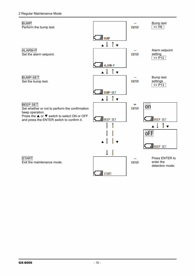
BUMP Perform the bump test.
Bump test => P6
ALARM-P Set the alarm setpoint.
Alarm setpoint setting => P12
BUMP-SET Set the bump test.
Bump test settings => P13
BEEP SET Set whether or not to perform the confirmation beep operation. Press the or switch to select ON or OFF and press the ENTER switch to confirm it.
START Exit the maintenance mode.
Press ENTER to enter the detection mode.
2 Regular Maintenance Mode
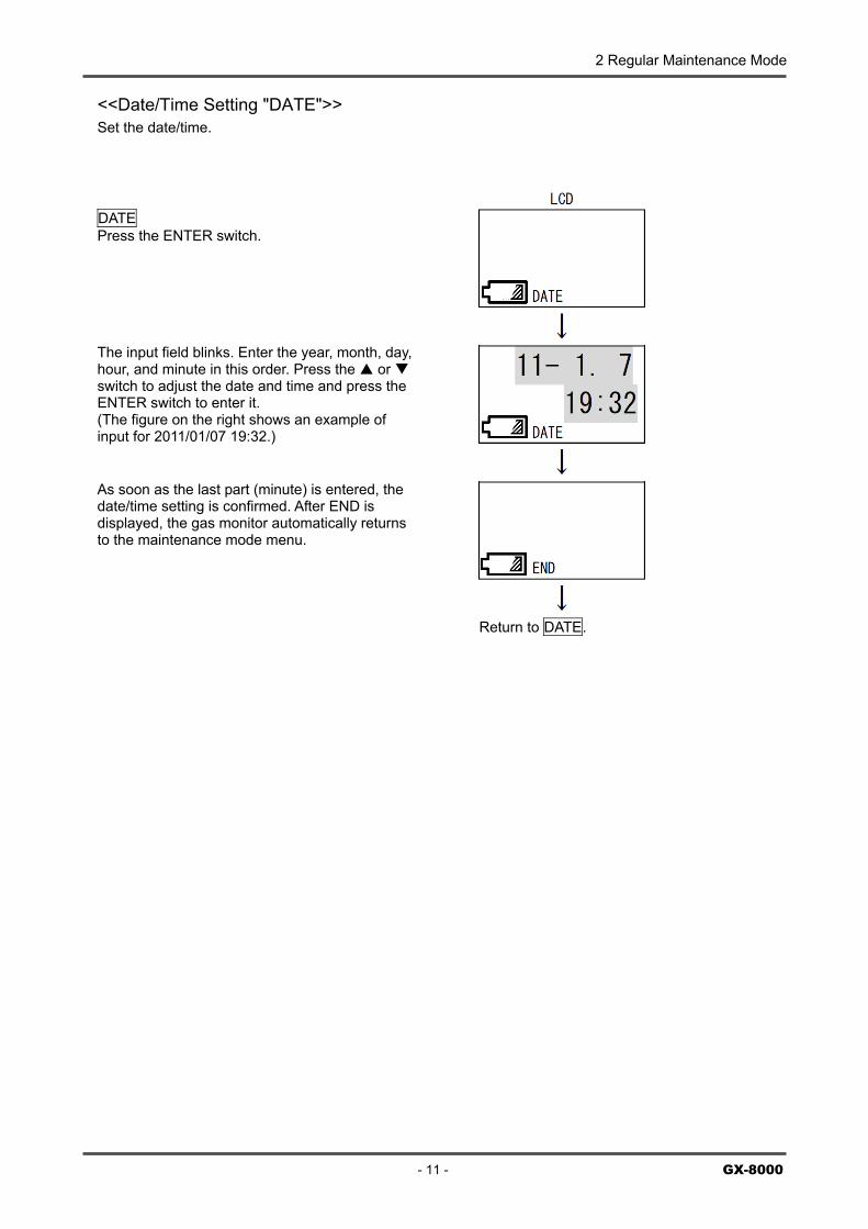
<<Date/Time Setting "DATE">> Set the date/time.
DATE Press the ENTER switch.
ThsE(i
Addt
he input field blinks. Enter the year, month, day,our, and minute in this order. Press the or witch to adjust the date and time and press the NTER switch to enter it.
The figure on the right shows an example of nput for 2011/01/07 19:32.)
- 11 - GX-8000
s soon as the last part (minute) is entered, the ate/time setting is confirmed. After END is isplayed, the gas monitor automatically returns
o the maintenance mode menu.
Return to DATE.
2 Regular Maintenance Mode
GX
<Alarm Setpoint Setting "ALARM-P"> Set the alarm setpoint.
ALARM-P Press the ENTER switch.
TdPwtca
WEt
Pv
CiC CAdtt
Wttm
he alarm setpoint setting selection menu is isplayed. ress the or switch to display a target gas for hich the alarm setpoint should be set. Every time
he or switch is pressed, the target gas is hanged (in the order of Combustible, O2, H2S, CO,
nd ESCAPE).
hile a desired target gas is selected, press the nter switch to cause the alarm setpoint display
o blink, prompting for input.
ress the or switch to change an alarm setpoint alue. Next, press the ENTER switch to enter it.
ontinue to set WARNING, ALARM, STEL, and TWA n this order. (Set the STEL and TWA alarms only for O and H S.)
-8000 - 12 -
2
hange the last item and press the ENTER switch. fter the changed settings are confirmed and END is isplayed, the gas monitor automatically returns to he alarm setpoint setting selection menu (*). Repeat he same procedure to set other target gases.
hen the alarm setpoint setting is completed, press he or switch until ESCAPE is displayed. Press he ENTER switch to return to the maintenance modeenu.
Return to ALARM-P.
2 Regular Maintenance Mode
<Bump Test Setting "BUMP-SET"> Check and set the setting items related to the bump test.
BUMP-SET Press the ENTER switch. Press the or switch to display a target setting item to be checked or set. TPbtte( TPpaTw(±
TPpais
WtPbttOt
Wss
he test time is displayed. ress the ENTER switch. The numeric display links, prompting for input. Press the or switch o enter introduction time. Press the ENTER switch o confirm it. The figure on the right shows an xample of 30 seconds. Test time: 30, 45, 60, or 90 seconds)
- 13 - GX-8000
he test pass tolerance range is displayed. ress the ENTER switch. The numeric display blinks,rompting for input. Press the or switch to enter range. Press the ENTER switch to confirm it. he figure on the right shows an example of range ithin ±30%.
Pass range: Within ±10%, ±20%, ±30%, ±40%, or 50%)
he adjustment time after test fail is displayed. ress the ENTER switch. The numeric display blinks,rompting for input. Press the or switch to enterdjustment time. Press the ENTER switch to confirm
t. The figure on the right shows an example of 60 econds.
hether or not to enable automatic adjustment after est fail is displayed. ress the ENTER switch. The ON (OFF) display links, prompting for input. Press the or switch o select ON or OFF. Next, press the ENTER switch o confirm it. ON: Automatic adjustment enabled FF:Automatic adjustment disabled The figure on
he right shows an example of ON setting.
hen the setting is completed, press the or witch until ESCAPE is displayed. Press the ENTER witch to return to the maintenance mode menu.
Return to BUMP-SET.
3 Span Adjustment 3-1. Preparation for span adjustment
GX-8000 - 14 -
3
Span Adjustment
3-1. Preparation for span adjustment Required equipment/material • Zero adjustment gas for high-concentration combustible gases (collected in a gas sampling bag) • Span adjustment gas (collected in a gas sampling bag) • Stopwatch Connection Connect the equipment as shown below to perform the span adjustment.
Gas
sampling bag
Gas sampling probe (with a tube)
GX-8000 main unit
GAS IN
GAS OUT (Open)
WARNING About the span adjustment gas The span adjustment gas is a hazardous gas (toxic, oxygen deficient, etc.). Handle the gas and related jigs and tools with due care (e.g., the gas must not be inhaled or the gas sampling bag must not have any hole). About the place for span adjustment • Perform span adjustment where no silicon, organic solvent, spray can gases, etc. are used. • Perform span adjustment indoors at normal temperature without remarkable fluctuation (within ±5°C). • Perform span adjustment in an exhaust booth.
CAUTION The GAS OUT side of the pipe must be left open without any pipe connected. A supplied gas must be discharged to a safe place.
3-1. Preparation for span adjustment 3 Span Adjustment
- 15 - GX-8000
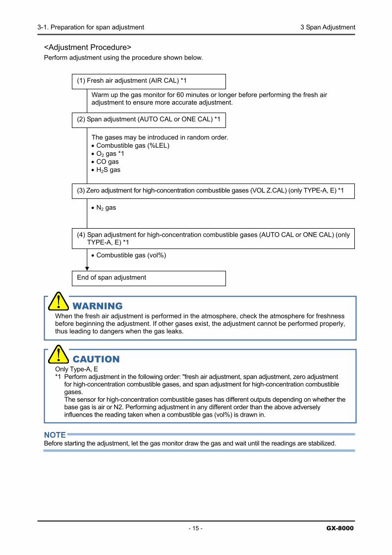
<Adjustment Procedure> Perform adjustment using the procedure shown below.
Warm up the gas monitor for 60 minutes or longer before performing the fresh air adjustment to ensure more accurate adjustment.
The gases may be introduced in random order. • Combustible gas (%LEL) • O2 gas *1 • CO gas • H2S gas
• N2 gas
• Combustible gas (vol%) NOTE Before starting the adjustment, let the gas monitor draw the gas and wait until the readings are stabilized.
(1) Fresh air adjustment (AIR CAL) *1
(2) Span adjustment (AUTO CAL or ONE CAL) *1
(3) Zero adjustment for high-concentration combustible gases (VOL Z.CAL) (only TYPE-A, E) *1
(4) Span adjustment for high-concentration combustible gases (AUTO CAL or ONE CAL) (only TYPE-A, E) *1
End of span adjustment
WARNING When the fresh air adjustment is performed in the atmosphere, check the atmosphere for freshness before beginning the adjustment. If other gases exist, the adjustment cannot be performed properly, thus leading to dangers when the gas leaks.
CAUTION Only Type-A, E *1 Perform adjustment in the following order: "fresh air adjustment, span adjustment, zero adjustment
for high-concentration combustible gases, and span adjustment for high-concentration combustible gases. The sensor for high-concentration combustible gases has different outputs depending on whether the base gas is air or N2. Performing adjustment in any different order than the above adversely influences the reading taken when a combustible gas (vol%) is drawn in.
3 Span Adjustment 3-2. Fresh air adjustment
GX-8000 - 16 -
3-2. Fresh air adjustment NOTE If the existence of other gases in the atmosphere is suspected before performing the fresh air adjustment, collect fresh air in the gas sampling bag and perform the adjustment using a gas supply adapter in the same way as for the span adjustment.
WARNING When the fresh air adjustment is performed in the atmosphere, check the atmosphere for freshness before beginning the adjustment. If other gases exist, the adjustment cannot be performed properly, thus leading to dangers when the gas leaks.
3-2. Fresh air adjustment 3 Span Adjustment
- 17 - GX-8000
AIR CAL Press the ENTER switch.
The current concentration readings of the gases are displayed. Press the AIR switch when they are stabilized.
When the AIR switch is pressed, HOLD AIR is displayed. Keep pressing the switch until RELEASE is displayed.
Release the AIR switch. * Only on TYPE-A and TYPE-E, a 30-second
countdown is started. No countdown is started on other types.
After the fresh air adjustment is successfully completed and END is displayed, the gas monitor automatically returns to the menu.
Return to AIR CAL.
3 Span Adjustment 3-3. Span adjustment
GX-8000 - 18 -
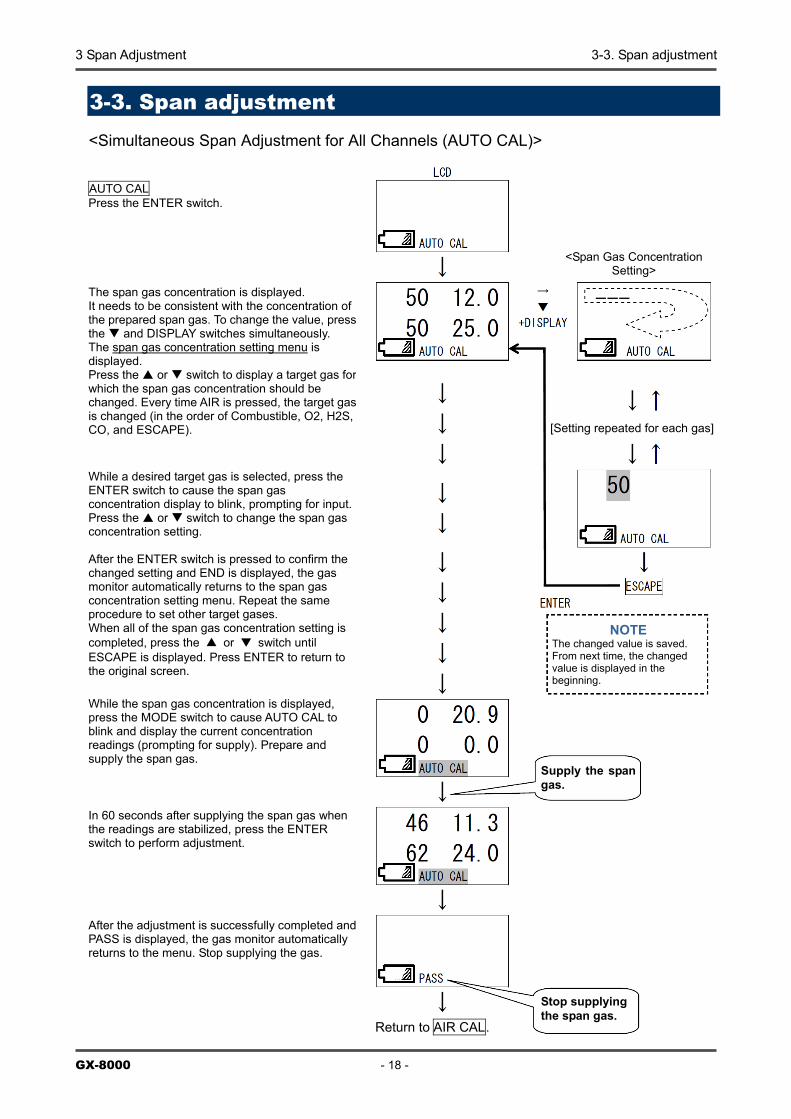
3-3. Span adjustment <Simultaneous Span Adjustment for All Channels (AUTO CAL)>
AUTO CAL Press the ENTER switch.
The span gas concentration is displayed. It needs to be consistent with the concentration of the prepared span gas. To change the value, press the and DISPLAY switches simultaneously. The span gas concentration setting menu is displayed. Press the or switch to display a target gas for which the span gas concentration should be changed. Every time AIR is pressed, the target gas is changed (in the order of Combustible, O2, H2S, CO, and ESCAPE).
While a desired target gas is selected, press the ENTER switch to cause the span gas concentration display to blink, prompting for input. Press the or switch to change the span gas concentration setting. After the ENTER switch is pressed to confirm the changed setting and END is displayed, the gas monitor automatically returns to the span gas concentration setting menu. Repeat the same procedure to set other target gases. When all of the span gas concentration setting is completed, press the ▲ or ▼ switch until ESCAPE is displayed. Press ENTER to return to the original screen.
While the span gas concentration is displayed, press the MODE switch to cause AUTO CAL to blink and display the current concentration readings (prompting for supply). Prepare and supply the span gas.
In 60 seconds after supplying the span gas when the readings are stabilized, press the ENTER switch to perform adjustment.
After the adjustment is successfully completed and PASS is displayed, the gas monitor automatically returns to the menu. Stop supplying the gas.
Return to AIR CAL.
<Span Gas Concentration Setting>
[Setting repeated for each gas]
NOTE The changed value is saved. From next time, the changed value is displayed in the beginning.
Supply the span gas.
Stop supplying the span gas.
3-3. Span adjustment 3 Span Adjustment
- 19 - GX-8000
<Span Adjustment for Each Channel (ONE CAL)>
ONE CAL Press the ENTER switch.
The span adjustment selection menu is displayed. Press the or switch to display a target gas for which the span adjustment should be performed. Every time the or switch is pressed, the target gas is changed (in the order of Combustible, O2, H2S, CO, and ESCAPE).
While a desired target gas is selected, press the ENTER switch to cause the concentration display to blink and display the current concentration readings (prompting for supply). Prepare and supply the span gas.
In 60 seconds after supplying the span gas when the readings are stabilized, press the or switch to adjust to the gas concentration.
Press the ENTER switch to adjust it. After END is displayed, the gas monitor automatically returns to the span adjustment for each channel menu (*). Stop supplying the gas. Repeat the same procedure to adjust other target gases.
When all of the span adjustment is completed, press the or switch until ESCAPE is displayed. Press the ENTER switch to return to the menu.
Return to ONE CAL.
Supply the span gas.
Stop supplying the span gas.
3 Span Adjustment 3-3. Span adjustment
GX-8000 - 20 -
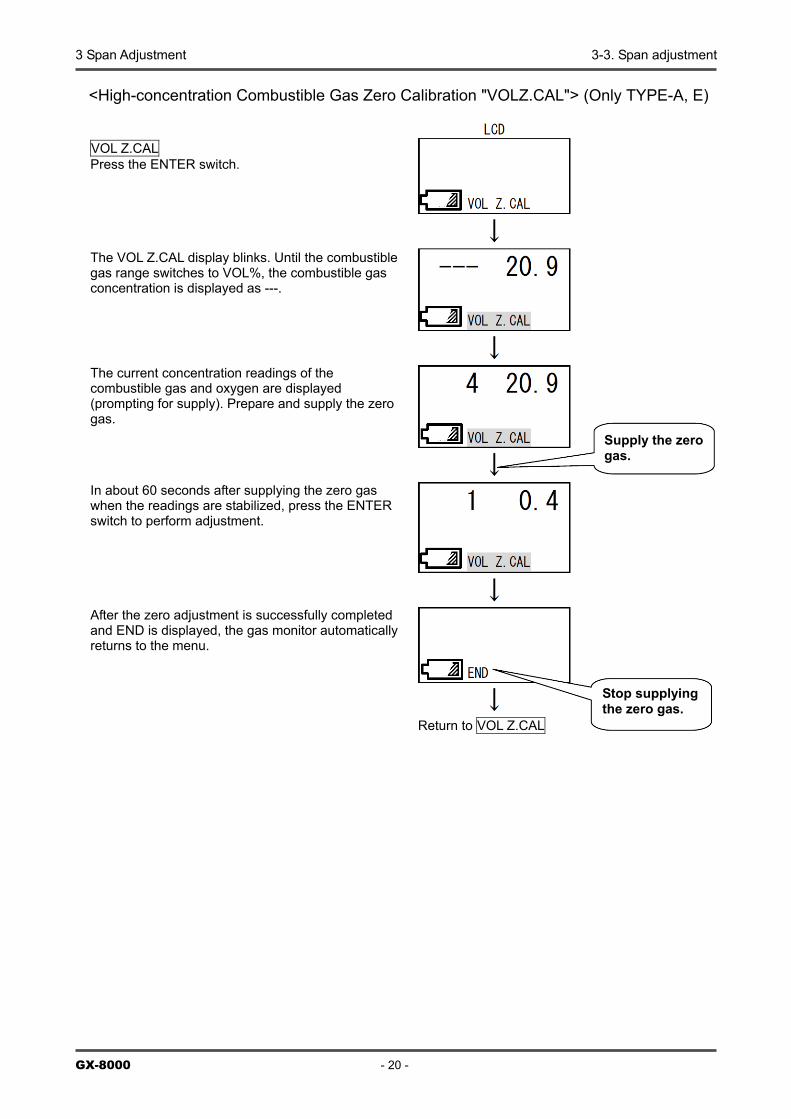
<High-concentration Combustible Gas Zero Calibration "VOLZ.CAL"> (Only TYPE-A, E)
VOL Z.CAL Press the ENTER switch.
Return to VOL Z.CAL
Stop supplying the zero gas.
The VOL Z.CAL display blinks. Until the combustible gas range switches to VOL%, the combustible gas concentration is displayed as ---.
The current concentration readings of the combustible gas and oxygen are displayed (prompting for supply). Prepare and supply the zero gas.
In about 60 seconds after supplying the zero gas when the readings are stabilized, press the ENTER switch to perform adjustment.
After the zero adjustment is successfully completed and END is displayed, the gas monitor automatically returns to the menu.
Supply the zero gas.
4 Replacement of Consumable Parts
GX-8000 - 21 -
4
Replacement of Consumable Parts
<Sensor Replacement Procedure> (1) Loosen the four screws on the sensor cover and remove the sensor cover. (2) Remove the sensor rubber seal.
Take care not to damage the sensor rubber seal and the seal surface inside the sensor cover that comes into contact with the rubber seal.
(3) Replace the sensor. Pay attention to the installation direction of the sensors. Check that the pins of the sensors are inserted firmly all the way (that the sensors have equal heights). Also, replace the rubber seals as required. Handle the rubber seals with care because any damage on them will impair the waterproof property.
CO sensor NC (%LEL) sensor
H2S sensor
TE(vol%) sensor O2 sensor
Sensor rubber seal Peel it off if it sticks to the sensor cover.
Sensor cover Captive screws
(four)
4 Replacement of Consumable Parts
GX-8000 - 22 -
(4) Using an opposite procedure to the above, install the sensor rubber seal and fix the sensor cover. Screw tightening torque: 5 to 5.5 kgf・cm (49 to 54 N・cm)
<Replacement Procedure for Other Consumable Parts> For the stable operation of the gas monitor and safety, a qualified service engineer is required to take care of replacement of the parts that requires high expertise. Please contact RIKEN KEIKI.
Sensor
Sensor rubber seal
Install the rubber seal so that the concave part covers the sensor.
Install the sensor cover horizontally so as not to warp the sensor rubber seal.
- 23 - GX-8000
Warranty Policy RIKEN KEIKI CO., LTD., warrants gas alarm equipment sold by us to be free from defects in materials, workmanship, and performance for a period of one year from date of shipment from RIKEN KEIKI CO., LTD., Inc. Any parts found defective within that period will be repaired or replaced, at our option, free of charge. This warranty does not apply to those items which by their nature are subject to deterioration or consumption in normal service, and which must be cleaned, repaired, or replaced on a routine basis. Warranty is voided by abuse including mechanical damage, alteration, rough handling, or repair procedures not in accordance with the operator’s manual. This warranty indicates the full extent of our liability, and we are not responsible for removal or replacement costs, local repair costs, transportation costs, or contingent expenses incurred without our prior approval.
THIS WARRANTY IS EXPRESSLY IN LIEU OF ANY AND ALL OTHER WARRANTIES AND REPRESENTATIONS, EXPRESSED OR IMPLIED, AND ALL OTHER OBLIGATIONS OR LIABILITIES ON THE PART OF RIKEN KEIKI CO., LTD., INCLUDING BUT NOT LIMITED TO, THE WARRANTY OF MERCHANTABILITY OR FITNESS FOR A PARTICULAR PURPOSE. IN NO EVENT SHALL RIKEN KEIKI CO., LTD., BE LIABLE FOR INDIRECT, INCIDENTAL, OR CONSEQUENTIAL LOSS OR DAMAGE OF ANY KIND CONNECTED WITH THE USE OF ITS PRODUCTS OR FAILURE OF ITS PRODUCTS TO FUNCTION OR OPERATE PROPERLY.
This warranty covers instruments and parts sold to users by authorized distributors, dealers, and representatives as appointed by RIKEN KEIKI CO., LTD. We do not assume indemnification for any accident or damage caused by the operation of this gas monitor, and our warranty is limited to the replacement of parts or our complete goods.