Research ArticleGyroscope Sensor Based In Vivo Finger Axes of RotationIdentification Using Screw Displacement
Yiming Zhu,1,2 Guowu Wei ,3 Lei Ren ,1 Zirong Luo,2 and Jianzhong Shang2
1School of Mechanical, Aerospace and Civil Engineering, The University of Manchester, Manchester, M13 9PL, UK2School of Mechatronics Engineering and Automation, National University of Defence Technology, 410073, China3School of Science, Engineering and Environment, University of Salford, Salford, M5 4WT, UK
This paper presents a low-cost, efficient, and portable in vivo method for identifying axes of rotation of the proximalinterphalangeal and distal interphalangeal joints in an index finger. The approach is associated with the screw displacementrepresentation of rigid body motion. Using the matrix exponential method, a detailed derivation of general spatial displacementof a rigid body in the form of screw displacement including the Rodrigues’ formulae for rotation is presented. Then, based on agyroscope sensor, a test framework for determining axes of rotation of finger joints is established, and experiments on findingthe directions of joint axes of the PIP and DIP joints are conducted. The results obtained highly agree with those presented inliterature through traditional but complex methods.
1. Introduction
For clinical, prosthetic, rehabilitation, and ergonomic appli-cations, an accurate model of the kinematics of the joints inthe fingers is essential for better understanding their normalfunction and pathology. The axes of rotation of the fingerjoints are crucial in the kinematic modelling and have greatimpact on muscle activation. Hence, knowledge of their loca-tion and orientation is important for constructing prostheticjoints and in the planning of reconstructive surgeries liketendon transfers [1]. So far, several different methods havebeen proposed for identifying the axes of rotation in humanhand joints. These include the mechanical approach by usingan “axis finder” to find axes of rotation in the thumb andindex finger metacarpophalangeal (MCP) joints and thethumb carpometacarpal (CMC) and interphalangeal (IP)joints [2, 3]; the MR image-based method for modelling theproximal interphalangeal (PIP) and distal interphalangeal(DIP) joint kinematics [4]; the CT image-based methodfor identifying the trapeziometacarpal joint during thumbextension/flexion and abduction/adduction [5]; the LEDand CT-based cadaveric investigation for PIP joint of an
index finger [6]; and the surface marker-based methodfor thumb carpometacarpal joint kinematics [7], for deter-mination of the centre of rotations (CORs) of the DIP,PIP, and MCP joints in the four fingers [8], and foridentification of centres and axes of rotation of wrist andfingers in hand kinematic modelling [9]. Except for the“axis finder,” the approaches presented previously arecostly and complex. However, the “axis finder” is basedon the assumption that the finger joint axis is fixed andcan only approximately find the rotation axis of a jointat one specified position per measurement. Hence, the“axis finder” cannot provide continuous measurement forthe whole range of motion of a finger joint and thus theaccurate vector of the average rotation axis.
In this paper, we propose an economic, intuitive, andportable measuring method based on gyroscope sensors.We show that combine with the screw displacement repre-sentation of rigid body motion, the proposed method isefficient for finding the axes of rotation of the PIP and DIPjoints, and for presenting kinematics of the middle and distalphalanges in an index finger. The finger joints are formed bybones which are commonly treated as rigid bodies, and,
HindawiApplied Bionics and BiomechanicsVolume 2021, Article ID 8871593, 10 pageshttps://doi.org/10.1155/2021/8871593
hence, the classical rigid body motion representationmethods can be used to describe the motion of bones andthe associated joints. Considering the motion of bones asgeneral spatial displacement, we introduce screw displace-ment representation [10] to present the motion of jointsand bones in fingers. Screw displacement is widely used inthe fields of kinematics, robotics, and computer vision butis not very popular in the field of biomechanics. To formulatethe screw displacement, there are mainly two approaches,one based on geometric and vector interpretation and theother with exponential derivation [11–14]. It is a very usefuland effective tool for identifying axes of rotation of joints andpresenting kinematics of fingers [15]. Hence, the detailedderivation of screw displacement of rigid body motion ispresented in detail in this paper.
This paper firstly presents the matrix-exponential-basedrepresentation of screw displacement of rigid body motionlaying background for the derivation and identificationof axes of rotation of finger joints. Then, a low-costgyroscope-sensor-based solution is proposed to identify thedirection vectors of the PIP and DIP joint axes in an indexfinger, providing an in vivo method for determining axes ofrotation of finger joints. Discussions of the results and limitsare addressed, and a conclusion is drawn.
2. Screw Displacement Representation of RigidBody Motion
In the human hand, bones are responsible for rigidity andjoints between the bones provide freedom of movement.Hence, assuming no deformation, motions among the bonesin the hand can be treated as rigid body motion. According toChasles’ theorem [10], the general motion between two rigidbodies is screwmotion as presented in exponential derivationof this section [11].
2.1. Exponential Derivation for Rotation. Rotation andtranslation combined leads to the general spatial motionof a rigid body in the three-dimensional space. There arecases that motion between two bodies is a pure rotationwhich can be mathematically presented with a rotationmatrix R that belongs to the special orthogonal group asR ∈ SOð3Þ. Referring to Figure 1, we find that the rotationmatrix can be expressed as a function of rotation angle θand a vector ω that presents the direction of the axis ofrotation.
Figure 1 shows the rotation of rigid body 1 with respect tobody 0 about an axis passing through pointO in the directionω which is coincident with the z-axis of a reference frameO − xyz. If the rigid body rotates at a constant unit angularvelocity about the axis ω, the velocity of a point P on thebody, denoted as _p, can be expressed as
_p tð Þ = ω × p tð Þ = ω½ �p tð Þ, ð1Þ
where ½ω� is the skew-symmetric matrix representation forthe cross product of vector ω, which complies with ½ω�T =
−½ω�. Equation (1) is a time-invariant differential equationwhich can be integrated resulting in
p tð Þ = e ω½ �tp 0ð Þ, ð2Þ
with pð0Þ and pðtÞ being the initial (at time t = 0) andcurrent (at time t) positions of point P, respectively (seeFigure 1), and the matrix exponential e½ω�t can be expressedin Taylor’s series form as
e ω½ �t = I + ω½ �t + ω½ �2t22! + ω½ �3t3
3! +⋯, ð3Þ
where I is a 3 × 3 identity matrix. Assuming that the rotationabout axis ω is a rotation with unit angular velocity for θunits of time, e½ω�t becomes e½ω�θ, and Eq. (3) thus becomes
e ω½ �θ = exp ω½ �θð Þ = I + ω½ �θ + ω½ �2θ22! + ω½ �3θ3
3! +⋯: ð4Þ
Considering the relations that ½ω�2 = ωωT − kωkI, ½ω�3 =− kωk2½ω�, and kωk = 1, Eq. (4) can be further expended as
e ω½ �θ = I + θ ω½ � + θ2
2! ω½ �2 − θ3
3! ω½ � − θ4
4! ω½ �2
+ θ5
5! ω½ � + θ6
6! ω½ �2 − θ7
7! ω½ � − θ8
8! ω½ �2+⋯
= I + θ −θ3
3! +θ5
5! −θ7
7! +⋯ !
ω½ �
+ θ2
2! −θ4
4! +θ6
6! −θ8
8! +⋯ !
ω½ �2:
ð5Þ
Using the relations that θ − θ3/3!+θ5/5!−θ7/7!+⋯ = sinθ and θ2/2!−θ4/4!+θ6/6!−θ8/8!+⋯ = 1 − cos θ, Eq. (5) canbe simplified as
e ω½ �θ = I + sin θ ω½ � + 1 − cos θð Þ ω½ �2= cos θI + sin θ ω½ � + 1 − cos θð ÞωωT :
ð6Þ
z
p(t)
p(0)
O
1
0
x
P
𝜃
y
ω
Figure 1: Rotation of rigid body 1 about the axis ω by an angle θ.
2 Applied Bionics and Biomechanics
Equation (6) is known as Rodrigues’ formula for a rota-tion of a rigid body about an arbitrary axis passing throughthe origin of a reference coordinate system. It is a rotationmatrix which can also be obtained through the geometricmethod [15]. Hence, expending Eq. (6) leads to a rotationmatrix
R ω½ �, θð Þ = e ω½ �θ = I + sin θ ω½ � + 1 − cos θð Þ ω½ �2
=
r11 r12 r13
r21 r22 r23
r31 r32 r33
26664
37775,
ð7Þ
where with the joint axis vector being ω = ½ωx, ωy, ωz�T , theelements rij in Eq. (7) are as follows: r11 = cos θ + ω2
xð1 −cos θÞ, r12 = ωxωyð1 − cos θÞ − ωz sin θ, r13 = ωxωzð1 − cosθÞ + ωy sin θ, r21 = ωyωxð1 − cos θÞ + ωz sin θ, r22 = cos θ +ω2yð1 − cos θÞ, r23 = ωyωzð1 − cos θÞ − ωx sin θ, r31 = ωzωx
ð1 − cos θÞ − ωy sin θ, r32 = ωzωyð1 − cos θÞ + ωx sin θ, andr33 = cos θ + ω2
zð1 − cos θÞ.Hence, substituting Eq. (7) into Eq. (2) implies that
e½ω�tpð0Þ has the effect of rotating point P about a fixedaxis ω by an angle θ to a new position pðtÞ.
Equation (7) is also known as the screw-axis represen-tation of the rotation of a rigid body. Such a representa-tion involves four parameters: three describing thedirection of the screw (joint axis) and one associated withthe angle of rotation, whereas only two of the three variablesgiving the direction of the screw axis are independentbecause they comply with the condition of a unit vector,i.e., ω2
x + ω2y + ω2
z = 1.Equation (7) indicates that for any rotation motion, there
always exists an instantaneous axis ω about which the rota-tion is associated together with the angle θ. Hence, giventhe joint axis vector and the angle of rotation, the nine ele-ments of the rotation matrix in Eq. (7) can be computed.On the other hand, given a rotation matrix R, the vector ofjoint axis (screw axis) ω and the angle of rotation θ can becalculated. Observing the elements in the rotation matrix inEq. (7), the angle of rotation θ can be obtained by addingthe diagonal elements of the rotation matrix as
θ = cos−1 trR − 12
� �= cos−1 r11 + r22 + r33 − 1
2
� �, ð8Þ
where trR stands for the trace of matrix R and trR = r11 +r22 + r33 = 1 + 2cosθ.
Further investigating the rotation matrix, direction of thescrew axis can be obtained by taking the differences betweeneach pair of the two opposing off-diagonal elements:
ω =ωx
ωy
ωz
2664
3775 = 1
2 sin θ
r32 − r23
r13 − r31
r21 − r12
2664
3775: ð9Þ
If represented in the skew-symmetric form, ½ω� can alsobe expressed as
ω½ � =0 −ωz ωy
ωz 0 −ωx
−ωy ωx 0
2664
3775 = R − RT� �
2 sin θ: ð10Þ
Since the angle θ in Eq. (8) has either positive or negativevalue, Eqs. (9) and (10) give two solutions of the screw axis,one being the negative of the other. However, the two solu-tions represent the same screw since a rotation of angle −θabout axis −ω has the same result as a rotation of θ aboutthe ω axis.
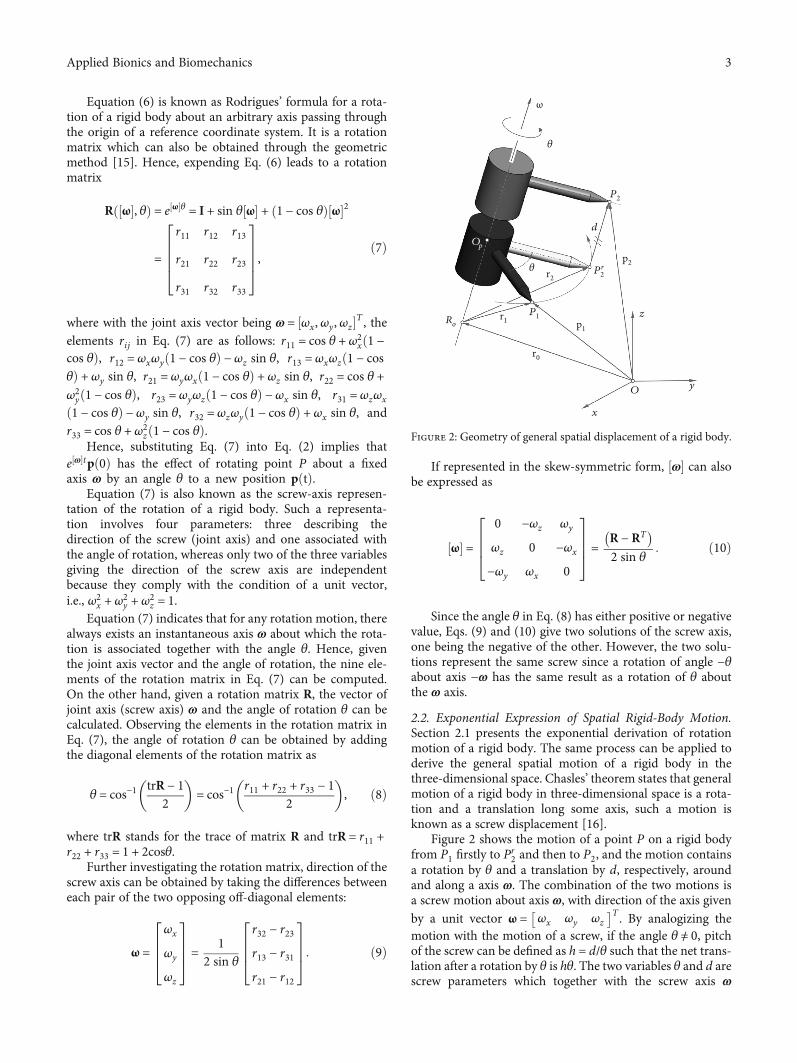
2.2. Exponential Expression of Spatial Rigid-Body Motion.Section 2.1 presents the exponential derivation of rotationmotion of a rigid body. The same process can be applied toderive the general spatial motion of a rigid body in thethree-dimensional space. Chasles’ theorem states that generalmotion of a rigid body in three-dimensional space is a rota-tion and a translation long some axis, such a motion isknown as a screw displacement [16].
Figure 2 shows the motion of a point P on a rigid bodyfrom P1 firstly to P
r2 and then to P2, and the motion contains
a rotation by θ and a translation by d, respectively, aroundand along a axis ω. The combination of the two motions isa screw motion about axis ω, with direction of the axis givenby a unit vector ω = ωx ωy ωz
� �T . By analogizing themotion with the motion of a screw, if the angle θ ≠ 0, pitchof the screw can be defined as h = d/θ such that the net trans-lation after a rotation by θ is hθ. The two variables θ and d arescrew parameters which together with the screw axis ω
P2
Op
ω
𝜃
𝜃
d
p2
p1
r2
r1
r0
P2r
Ro
P1 z
y
x
O
Figure 2: Geometry of general spatial displacement of a rigid body.
3Applied Bionics and Biomechanics
completely define the general displacement of a rigid body inthe three-dimensional space.
Referring to Figure 2, ω is the axis direction with kωk = 1,and r0 is the vector for a point R0 on the axis. Let the rigidbody rotate about axis ω by an angular velocity of _θωtogether with a translational velocity of _dω = h _θω, and thevelocity of point P at pðtÞ can be written as
_p tð Þ = ω × p tð Þ − r0ð Þ + hω: ð11Þ
This equation can be represented in a homogeneousmatrix form as
_p
0
" #=
ω½ � −ω × r0 + hω
0 0
" # p
1
" #
=ω½ � v
0 0
" # p
1
" #= S½ �
p
1
" #,
ð12Þ
where v = −ω × r0 + hω, and hence, there exists
_�p tð Þ = S½ ��p tð Þ: ð13Þ
Similar to solving the rotation case in Eq. (1), Eq. (13) canbe solved as
�p tð Þ = e S½ �t�p 0ð Þ, ð14Þ
where the matrix exponential of matrix ½S� can be derivedwith Taylor’s series as
e S½ �t = I + S½ �t + S½ �tð Þ22! + S½ �tð Þ3
3! +⋯, ð15Þ
and if assuming that the rigid body rotates about axis ω at aunit velocity for θ units of time, Eq. (15) becomes
T = e S½ �θ = I + S½ �θ + S½ �2 θ2
2! + S½ �3 θ3
3! +⋯, ð16Þ
with ½S�2 = ½ω�2 v
0 0
" #, ½S�3 = ½ω�3 ½ω�2v
0 0
" #, ½S�4 =
½ω�4 ½ω�3v0 0
" #,
And, hence, considering Eqs. (5) and (6), it has
T = e S½ �θ =e ω½ �θ Q θð Þv0 1
" #=
R q
0 1
" #, ð17Þ
where the term QðθÞ is
Q θð Þ = Iθ + ω½ � θ2
2! + ω½ �2 θ3
3! + ω½ �3 θ4
4! +⋯
= Iθ + θ2
2! −θ4
4! +θ6
6! −⋯ !
ω½ �
+ θ3
3! −θ5
5! +θ7
7! −⋯ !
ω½ �2
= Iθ + 1 − cos θð Þ ω½ � + θ − sin θð Þ ω½ �2:
ð18Þ
Using the identities that ½ω�2ω = 0 and ½ω�3 = −½ω�, andwith v = −ω × r0 + hω, the term QðθÞv can be derived as
= hθω − 1 − cos θð Þ ω½ �2r0 − sin θ ω½ �r0= I − e ω½ �θ�
r0 − hθω = I − Rð Þr0 − dω = q:
ð19Þ
Expending Eq. (19) gives
q =qx
qy
qz
2664
3775 =
dωx − r0x r11 − 1ð Þ − r0yr12 − r0zr13
dωy − r0xr21 − r0y r22 − 1ð Þ − r0zr23
dωz − r0xr31 − r0yr32 − r0z r33 − 1ð Þ
2664
3775:
ð20Þ
Substituting Eq. (19) into Eq. (17), the transformationmatrix T becomes
T = e ω½ �θ =R q
0 1
" #
=e ω½ �θ I − e ω½ �θ
� r0 + hθω
0 1
24
35 =
R I − Rð Þr0 + dω
0 1
" #:
ð21ÞIn addition, using the relation that ωTv =ωTð−ω × r0Þ +
hωTω such that h =ωTv and r0 =ω × v, Eq. (21) can also beexpressed as
T = e ω½ �θ =e ω½ �θ I − e ω½ �θ
� ω × vð Þ + ωωTvθ
0 1
24
35
=e ω½ �θ I − e ω½ �θ
� ω½ � + ωωTθ
h iv
0 1
24
35:
ð22Þ
4 Applied Bionics and Biomechanics
In the case that the motion is pure translation with kωk = 0and kvk = 1, it has R = e½ω�θ = I such that
T = e S½ �θ =I dv
0 1
" #: ð23Þ
On the other hand, in the case that the motion is purerotation with h = d = 0 and kωk = 1, it has
T = e S½ �θ =e ω½ �θ I − e ω½ �θ
� r0
0 1
24
35
=e ω½ �θ I − e ω½ �θ
� ω × vð Þ
0 1
24
35:
ð24Þ
In the above equations r0 = ½r0x r0y r0z�T is a vector for apoint on the screw axis and is perpendicular to the axis (seeFigure 2).
There are eight parameters required in the above deriva-tion of a spatial displacement, three for presenting directionof the screw axis ω, three for locating of the screw axis, i.e.,r0, one for the rotation angle θ, and one for the translationaldistance d. However, the three parameters relative to thedirection of screw axis must comply with ωTω = 1, and,hence, only two of them are independent. In addition, onlytwo of the three parameters that depict location of the screwaxis are independent, since there exits the relationship thatr0T ω = 0. In summary, only six of the eight parameters areindependent.
Therefore, from the above derivation, given the sixparameters for describing the screw axis and the associatedvariables, the transformation matrix for spatial displacementin Eqs. (21) and (22) can be obtained. On the other hand,providing a specified spatial displacement of a rigid bodywith a rotation matrix R and a position vector q, angle ofrotation θ can be found using Eq. (8), direction of the screwaxis can be solved with Eq. (9) or Eq. (10), and the transla-tional displacement d can be calculated with
d = ωTqωk k2 : ð25Þ
Since these equations are linear, there exists one solutioncorresponding to each solution set of ω, θ, and d.
The screw displacement form of general spatial motionderived above lays background for the kinematic analysis ofrobot manipulator with transform operator approach [17],which is also known as POE (product of exponential)method [13]. The POE presentation of robotic kinematics isdifferent from the Denavit-Hartenberg convention [18] inthe setting of coordinate frames and system variables. In thispaper, the screw displacement approach presented above isused in the identification and representation of joint axes ofrotation of human fingers.
3. Gyroscope Sensor-Based In Vivo Finger JointAxis Identification
The axis of rotation between two bones is loosely defined as aline that does not move with respect to either bone while thebones move around each other [1]. Identifying finger joinaxis is important in constructing prosthetic joints and inplanning reconstructive surgery of human finger. In this sec-tion, a novel and efficient method is presented for in vivo fin-ger joint axis identification.
3.1. Representation of Joint Axis Using Screw Displacement. Ahuman finger contains three phalanges connected by threejoints including the metacarpophalangeal (MCP) joint, prox-imal interphalangeal (PIP) joint, and distal interphalangeal(DIP) joint. Actuated by extrinsic and intrinsic muscles (sixor seven for the fingers and eight for the thumb), the fingerscan perform agile movement leading to the grasping and dex-terous manipulation of human hand. In the kinematicmodelling of the fingers, it is commonly assumed that thejoint axes of the PIP and DIP joints are parallel to each otherand perpendicular to the sagittal plane. However, theseassumptions are not accurate since the joint axes in humanfinger have neither parallel nor perpendicular relationships.The joint axes are formed according to the shapes of thebones, leading to the so-called conjoint rotations of the jointsand the three-dimensional movements of the fingers [1, 20].As pointed out in [1], the joint axes are assumed to be fixedwith respect to the associated phalanges and can be identifiedwith various methods [2–8]. This paper proposes a low-costand efficient method for identifying the axes of DIP andPIP joints in the fingers. The proposed method is related tothe screw displacement representation derived in Section 2.
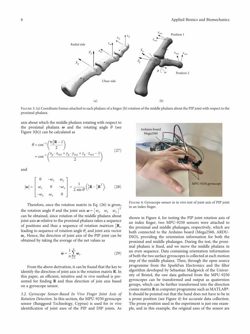
Figure 3(a) shows a finger with three coordinate framesfOpg, fomg, and fodg attached to the centres of the head ofthe proximal, middle, and distal phalanges, respectively. Atthe anatomical position, as shown in Figure 3(a), the orienta-tions of frames fOpg, fomg, and fodg are coincident. Theframes are defined in such a manner of the x-axis is alongthe radial-ulnar direction, the y-axis is along the proximal-distal direction, and the z-axis is along the dorsal-palmardirection. Taking the motion of the middle phalanx aboutthe PIP joint with respect to the proximal phalanx as anexample, referring to Figure 3(b), if the middle phalanxrotates from position 1 (at anatomical position such thatframe fomg aligns with frame fOpg) to position 2, withrespect to frame fOpg, the change of orientation of the mid-dle phalanx, which is reflected in orientation change of framefomg, can be expressed in a rotation matrix of directioncosine form [13] as
12R =
xp ⋅ xm2 xp ⋅ ym2 xp ⋅ zm2
yp ⋅ xm2 yp ⋅ ym2 yp ⋅ zm2
zp ⋅ xm2 zp ⋅ ym2 zp ⋅ zm2
2664
3775: ð26Þ
With this rotation matrix and considering the relationthat 12R = Rðω, θÞ, using Eq. (8) and Eq. (9) or (10), the joint
5Applied Bionics and Biomechanics
axis about which the middle phalanx rotating with respect tothe proximal phalanx ω and the rotating angle θ (seeFigure 3(b)) can be calculated as
θ = cos−1 tr12R − 12
� �
= cos−1xp ⋅ xm2 + yp ⋅ ym2 + zp ⋅ zm2 − 1
2
� � ð27Þ
and
ω½ � =0 −ωz ωy
ωz 0 −ωx
−ωy ωx 0
2664
3775 = 1
2 sin θ12R − 1
2RT
� : ð28Þ
Therefore, once the rotation matrix in Eq. (26) is given,the rotation angle θ and the joint axis ω = ωx ωy ωz
� �Tcan be obtained, since rotation of the middle phalanx aboutjoint axis ω relative to the proximal phalanx takes a sequenceof positions and thus a sequence of rotation matrices 1
2Ri,leading to sequence of rotation angle θi and joint axis vectorωi. Hence, the direction of joint axis of the PIP joint can beobtained by taking the average of the net values as
�ω = 1n〠n
i=1ωi: ð29Þ
From the above derivation, it can be found that the key toidentify the direction of joint axis is the rotation matrix R. Inthis paper, an efficient, intuitive and in vivo method is pre-sented for finding R and thus direction of join axis basedon a gyroscope sensor.
3.2. Gyroscope Sensor-Based In Vivo Finger Joint Axis ofRotation Detection. In this section, the MPU-9250 gyroscopesensor (Banggood Technology, Cyprus) is used for in vivoidentification of joint axes of the PIP and DIP joints. As
shown in Figure 4, for testing the PIP joint rotation axis ofan index finger, two MPU-9250 sensors were attached tothe proximal and middle phalanges, respectively, which areboth connected to the Arduino board (Mega2560, ARDU-INO), providing the orientation information for both theproximal and middle phalanges. During the test, the proxi-mal phalanx is fixed, and we move the middle phalanx inan even sequence. Data containing orientation informationof both the two surface gyroscopes is collected at each motionstep of the middle phalanx. Then, through the open sourceprogramme from the SparkFun Electronics and the filteralgorithm developed by Sebastian Madgwick of the Univer-sity of Bristol, the raw data gathered from the MPU-9250gyroscopes can be transformed and output as quaterniongroups, which can be further transformed into the directioncosine matrix R in computer programme such as MATLAB®.It should be pointed out that the hand does not have to be ina prone position (see Figure 4) for accurate data collection.The prone position used in the experiment is just one exam-ple, and in this example, the original axes of the sensor are
zd
odyd
om
Op
Yp
ym
xd
zm
xmZp
Xp
Radial side
Ulnar side
(a)
ω𝜃
xm1
zm1
Xp
Zp
om1
ym1
ym2
xm2 zm2
om2Op
Yp
Position 1
Position 2
(b)
Figure 3: (a) Coordinate frames attached to each phalanx of a finger; (b) rotation of the middle phalanx about the PIP joint with respect to theproximal phalanx.
MPU-9250 gyroscope
Arduino boardMega2560
Figure 4: Gyroscope sensor in in vivo test of joint axis of PIP jointin an index finger.
6 Applied Bionics and Biomechanics
located at the initial position aligned with the directions ofgravity (minus z-axis of the sensor) and geomagnetism (x-axis of the sensor). Besides, we put the finger joint at the edgeof the table to avoid the movement of the proximal phalanxso as to reduce the errors of its position measurement.
Once the sequence of rotation matrices 12Ri is obtained
through the above tests, the joint axis of the PIP joint can becomputed. Similarly, by placing one additional sensor on thedistal phalanx, the joint axis of the DIP joint can be determined.
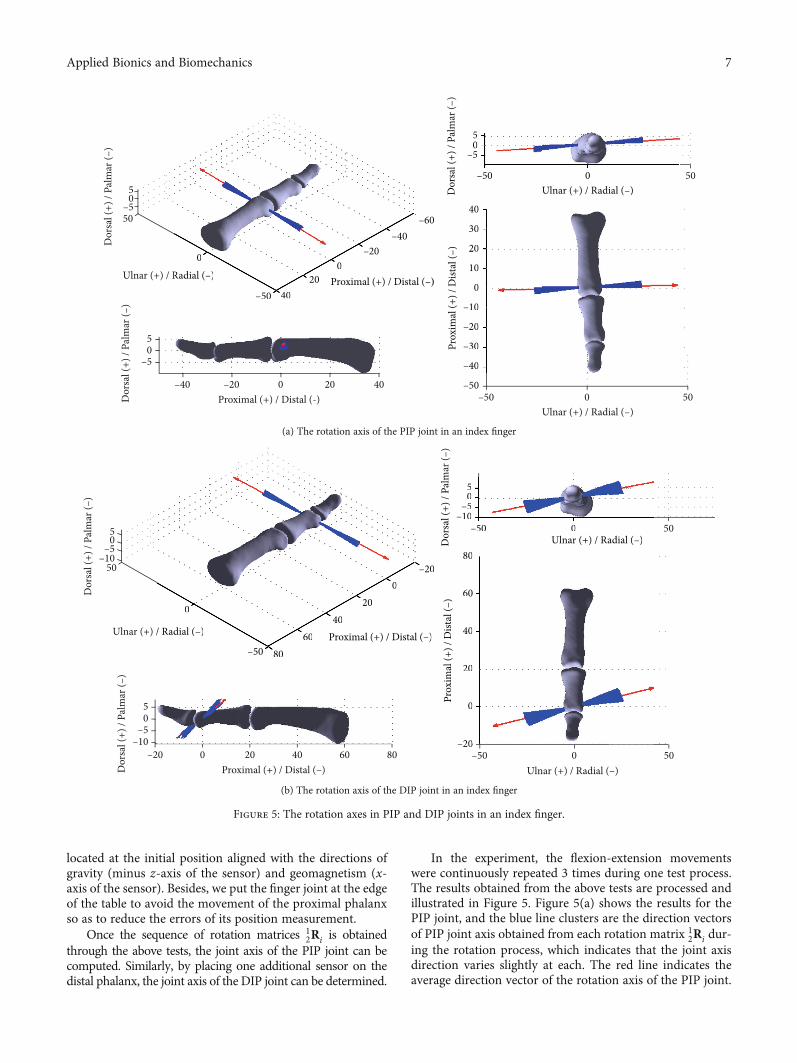
In the experiment, the flexion-extension movementswere continuously repeated 3 times during one test process.The results obtained from the above tests are processed andillustrated in Figure 5. Figure 5(a) shows the results for thePIP joint, and the blue line clusters are the direction vectorsof PIP joint axis obtained from each rotation matrix 1
2Ri dur-ing the rotation process, which indicates that the joint axisdirection varies slightly at each. The red line indicates theaverage direction vector of the rotation axis of the PIP joint.
Ulnar (+) / Radial (–)
Proximal (+) / Distal (-)
Proximal (+) / Distal (–)
Prox
imal
(+) /
Dist
al (–
)Dor
sal (
+) /
Palm
ar (–
)D
orsa
l (+)
/ Pa
lmar
(–)
–50 4020
–20–40
–60
00
50–5
05
–5
–40 –20 0 20 40
05
Ulnar (+) / Radial (–)Dor
sal (
+) /
Palm
ar (–
)
–5
–50 0 50
05
Ulnar (+) / Radial (–)
–50
–40
–30
–20
–10
0
10
20
40
30
–50 0 50
Radial (–) Proximal (+) / Distal (–)
Prox
imal
(+) /
Dist
al (–
)
–50 4020
–20–40
–60
00
Ulnar (+) / Radial (–)Dor
sal (
+) /
Pa
–5
–50 0
05
–40
–30
–20
–10
0
10
20
40
30
(a) The rotation axis of the PIP joint in an index finger
Ulnar (+) / Radial (–) Proximal (+) / Distal (–)
Prox
imal
(+) /
Dist
al (–
)Dor
sal (
+) /
Palm
ar (–
)
Proximal (+) / Distal (–)Dor
sal (
+) /
Palm
ar (–
)
–505
–10–20 0 20 40 60 80
Dor
sal (
+) /
Palm
ar (–
)
–505
–10
Ulnar (+) / Radial (–)–50 0 50
80
60
40
20
0
–20
Ulnar (+) / Radial (–)–50 0 50
–50 8060
4020
0–20
0
50–10
–505
/ Radial (–) Proximal (+) / Distal (–)
Prox
imal
(+) /
Dist
al (–
)D
orsa
l (+)
/ Pa
lm
–505
–10
Ulnar (+) / Radial (–)–50 0
80
60
40
20
0
20
–50 8060
4020
0–20
0
(b) The rotation axis of the DIP joint in an index finger
Figure 5: The rotation axes in PIP and DIP joints in an index finger.
7Applied Bionics and Biomechanics
From the figure, it can be found that presented in the coordi-nate frame fOpg, for the PIP joint in the index finger, the
average direction vector of the joint axis is �ωPIP =0:998 0:024 0:061½ �T with around ±3.5° variation, ofwhich the variation of the joint axis is the maximum anglebetween the average joint axis vector (red line) and eachinstantaneous joint axis vector (blue line). The maximumangle was identified by using the embedded MATLAB com-mand. Similarly, presented in the coordinate frame fomg,for the DIP joint, the direction vector of the joint axis is�ωDIP = 0:955 0:231 0:184½ �T with around ±5° variation.Accordingly, a 14° orientation difference can be foundbetween the average rotation axes of PIP and DIP joints.The result is consistent with the description of the cadaverictests presented in Ref. [4, 6].
Further, using the screw displacement transformationderived in Section 2.2, based on the rotation axes of the PIPand DIP joints in an index finger identified above, motion ofthe distal endpoint with respect to the PIP joint can be formu-lated and characterised. Let us define the natural anatomicalposition as the reference (zero) position, give the screw axesof the PIP and DIP joints as ωPIP = ω2 = ð0:998, 0:024, 0:061Þ and ωDIP = ω3 = ð0:955, 0:231, 0:184Þ as identified fromthe above in vivo tests, and specify the lengths of the middleand distal phalanges as l2 = 23:16mm and l3 = 15:83mm,respectively. Forward kinematics of the distal and middlephalanges relative to the PIP joint can be formulated as
TOpOd= e S2½ �θ2e S3½ �θ3MOd
, ð30Þ
where in coordinate frame fOpg, there are S2 = ðω2, r2 × ω2Þwith r2 = ð0,−l2, 0Þ and S3 = ðω3, r3 × ω3Þ with r3 = ð0,−ðl2
+ l3Þ, 0Þ and MOd, and the position vector of point od in
the zero configuration expressed in the reference frame fOpg as
MOd=
1 0 0 00 1 0 −l2 − l3
0 0 1 00 0 0 1
2666664
3777775: ð31Þ
Substituting the parameters into Eqs. (24) and (30) andusing the experimental joint angle range of the PIP andDIP joints from [15] as θ2 ∈ ½0, 101°� and θ3 ∈ ½0, 73°�, work-space of the fingertip (i.e., point od) can be calculated andplotted as shown in Figure 6. One can see that the work-space is distributed in a three-dimensional space rather thanon a plane. This workspace is generated due to the offset ofthe axes of rotation of the PIP and DIP joints from theiranatomical planes, which leads to the conjoint rotation,and thus the three-dimensional motion of the fingertip.
4. Discussions
From the above derivation and investigation, we found thatthe rotation axes of the PIP and DIP joints are offset fromthe anatomical planes, such an arrangement leads to conjointrotations [1] that generate three-dimensional motion fordexterous grasping and manipulation of hand with fewerjoints. The axes of rotation of the PIP and DIP joints arenot fixed but vary throughout the range of motion of thejoints. This agrees with the statements in [19, 20]. As pointedout in [20], the finger joints are synovial joints which move
40 –1040
20
0
–20
–40
100200–20–40–40
–20
0
20
Ulnar (+) / Radial (–)
Ulnar (+) / Radial (–)
Proximal (+) / Distal (–)
Proximal (+) / Distal (–)
Prox
imal
(+) /
Dist
al (–
)
Dor
sal (
+) /
Palm
ar (–
)D
orsa
l (+)
/ Pa
lmar
(–)
Dor
sal (
+) /
Palm
ar (–
)
–10–40
–200
20–505
–10–20–30
0–40
–30
–20
–10
0
100Ulnar (+) / Radial (–)
40
20
0
–20
–40
)Proximal (+) / Distal (–)
Prox
imal
(+) /
Dist
al (–
)D
orsa
l(+)
/ Pa
lmar
(–)
–10–40
–200
20–50
–40
–30
–20
–10
0
10Ulnar (+) / Rad
Figure 6: Workspace of the fingertip with respect to frame fOpg based on the identified rotation axes of the PIP and DIP joints in anindex finger.
8 Applied Bionics and Biomechanics
with both rotation and sliding, and, hence, the axes of rota-tion are the evolute of the serial of locations of the instanta-neous axes of rotation. In clinical practice and in ordinaryclinical situations [1], simplification to an average axis ofrotation, like formulated in Eq. (29), is assumed to occurthroughout the entire range of motion of a joint. This averagedirection of axis is located by an anatomic landmark thatpierces the convex member of the two bones forming thejoint. The results obtained by the proposed method in thispaper also agree with the experimental results in [21], whichindicates that the PIP and DIP joint axes are not fixed, thejoints are approximately parallel to the flexion-extensioncreases [1, 2], and are approximately perpendicular to thebone segments in full extension, but progressively are obliqueduring flexion. The MR image measurement in [4] showedchanges of up to 14° in the directions of the PIP and DIPjoint axes during motion. In [22], based on the 3Dscanned data, the changes of axes of rotation of fingerjoints during motion were characterised as surface ofscrews based on screw theory, and the results are similarto those illustrated in Figure 5 in this paper. In addition,we found that the proposed method was more efficientthan the “axis finder” [2]. If we want to identify the rota-tion axes of the MCP joint in both flexion-extension andabduction-adduction planes, the “axis finder” system needsto be reconstructed to find the rotation axis in differentplanes. But using the proposed gyroscope sensor, we cankeep the same position of the sensors to identify all therotation axes in one joint.
Further, the experimental results obtained in this paperhave some errors because of the noise in the sensor’s signalsand the deformation of the finger tissue and skin during themovement. In addition, the rotation axis direction in the fin-ger joint can be quite different between individuals, and, thus,for clinical and medical applications, the test needs to be car-ried out individually. The above experimental setup, testingprocess, and data processing method hence provide an effi-cient, convenient, and intuitive approach for identifyingrotation joint axis in human fingers. This approach is effi-cient for not only the PIP and DIP joints in the fingers andIP joint in the thumb, but also the MCP and CMC joints.In order to identify the joint axis vectors of the DIP, PIP,andMCP joints in the fingers at the same time, the additionalsensors need to be placed on the distal, middle, and proximalphalanges and the metacarpal bone. Otherwise, two sensorsare enough for one joint axis identification even there aremore than one degree of freedom. These will be investigatedin our future research.
Therefore, in this paper, a low-cost, efficient, and intu-itive in vivo approach is proposed for detecting axes ofrotation of the PIP and DIP joints of the index finger.Using the proposed method, rotation axes of the onedegree of freedom joints in the hand can be convenientlyidentified. The method can be extended to the identifica-tion of axes of rotation of PIP and DIP joints of the otherfingers and IP joint of the thumb, and it can be alsopotentially extended for determining axes of rotation ofthe other synovial joints, such as knee joint and elbowjoint, in the human body.
5. Conclusion
Kinematics and axes of rotation of human joints are impor-tant in constructing prosthetic joints and planning recon-structive surgery, and, hence, various methods includinggoniometry, mechanical finder, MR and CT images, and sur-face markers have been used to identify the axes of rotation ofjoints, especially finger joints. In this paper, a low-cost,intuitive, and portable in vivo method based on gyroscopesensors was for the first time proposed for detecting axes ofjoints of the PIP and DIP joints in an index finger. Theproposed experimental method was integrated with screwdisplacement representation of rigid body motion, andthe matrix exponential-based derivation of general spatialdisplacement was described in a detailed manner, provid-ing background for wider applications in the field of bio-mechanics. The experimental results demonstrated theefficiency and effectiveness of the proposed method, andthe results are comparable and agree with the previouspublished works [4, 6].
Data Availability
No data are associated with this paper.
Conflicts of Interest
The authors declare that there is no conflict of interestregarding this publication.
Acknowledgments
This work is partly supported by the projects of the NationalNatural Science Foundation of China under grant No.91948302 and No. 91848204 and the project of NationalKey R&D Program of China under No. 2018YFC2001300.
References
[1] P. W. Brand and A. Hollister, Clinical Mechanics of the Hand,Mosby, St. Louis, Missouri, 3rd Ed edition, 1999.
[2] A. Hollister, D. J. Giurintano, W. L. Buford, L. M. Myers, andA. Novick, “The axes of rotation of the thumb interphalangealand metacarpophalangeal joints,” Clinical Orthopaedics andRelated Research, vol. 320, pp. 188–193, 1995.
[3] J. Agee, A. M. Hollister, and F. King, “The longitudinal axis ofrotation of the metacarpophalangeal joint of the finger,” Jour-nal of Hand Surgery, vol. 11A, p. 767, 1986.
[4] N. Miyata, M. Louchi, M. Mochimaru, and T. Kurihara,“Finger joint kinematics from MR images,” in 2005 IEEE/RSJInternational Conference on Intelligent Robots and Systems,pp. 2750–2755, Edmonton, Alta., Canada, Aug. 2005.
[5] J. J. Crisco, E. Halilaj, D. C. Moore, T. Patel, A. C. Weiss, andA. L. Ladd, “In vivo kinematics of the trapeziometacarpal jointduring thumb extension-flexion and abduction-adduction,”The Journal of Hand Surgery, vol. 40, no. 2, pp. 289–296, 2015.
[6] F. Hess, P. Furnstahl, L.-M. Gallo, and A. Schweizer, “3D anal-ysis of the proximal interphalangeal joint kinematics duringflexion,” Computational and Mathematical Methods in Medi-cine, vol. 2013, Article ID 138063, 2013.
9Applied Bionics and Biomechanics
[7] L. Y. Chang and N. S. Pollard, “Method for determining kine-matic parameters of theIn VivoThumb carpometacarpaljoint,” IEEE Transactions on Biomedical Engineering, vol. 55,no. 7, pp. 1897–1906, 2008.
[8] X. Zhang, S.-W. Lee, and P. Braido, “Determining finger seg-mental centers of rotation in flexion-extension based on sur-face marker measurement,” Journal of Biomechanics, vol. 36,no. 8, pp. 1097–1102, 2003.
[9] P. Cerveri, N. Lopomo, A. Pedotti, and G. Ferrigno, “Deriva-tion of centers and axes of rotation for wrist and fingers in ahand kinematic model: methods and reliability results,”Annals of Biomedical Engineering, vol. 33, no. 3, pp. 402–412,2005.
[10] J. S. Dai, “Finite displacement screw operators with embeddedChasles’ motion,” Journal of Mechanisms and Robotics, vol. 4,no. 11, article 041002, 2012.
[11] R. M. Murray, Z. Li, and S. S. Sastry, AMathematical Introduc-tion to Robotic Manipulation, CRC Press, Boca Raton, FL,1994.
[12] K. M. Lynch and F. C. Park, Modern Robotics: Mechanics,Planning, and Control, Cambridge University Press, NY, 2017.
[13] R. W. Brockett, “Robotic Manipulators and the Product ofExponential Formula,” in Mathematical Theory of Networksand Systems, pp. 120–129, Springer Berlin Heidelberg, Berlin,Heidelberg, 1984.
[14] G. Wei, A. H. Jones, and L. Ren, “Note on Geometric andExponential Expressions of Screw Displacement,” in TowardsAutonomous Robotic Systems. TAROS 2019. Lecture Notes inComputer Science, vol 11649, K. Althoefer, J. Konstantinova,and K. Zhang, Eds., pp. 401–412, Springer, Cham, 2019.
[15] E. Y. S. Chao, K.-N. An, P. W. Cooney III, and R. L. Linscheid,Biomechanics of the Hand: A Basic Research Study, World Sci-entific Publishing Co. Pte. Ltd., Farrer Road, Singapore, 1989.
[16] O. Bottema and B. Roth, Theoretical Kinematics, North Hol-land Publishing Company, Amsterdam, 1979.
[17] J. J. Craig, Introduction to Robotics: Mechanics and Control,Pearson Education, Inc., Upper Saddle River, New Jersey, 4thedition, 2018.
[18] J. Denavit and R. S. Hartenberg, “A kinematic notation forlower pair mechanisms based on matrices,” Journal of AppliedMechanics, vol. 77, pp. 215–221, 1955.
[19] C. Dumont, G. Albus, D. Kubein-Meesenburg, J. Fanghänel,K. M. Sturmer, and H. Nagerl, “Morphology of the interpha-langeal joint surface and its functional relevance,” The Journalof Hand Surgery, vol. 33, no. 1, pp. 9–18, 2008.
[20] L. K. Sara and D. A. Neumann, “Basic Structure and Functionof Human joints,” in Kinesiology of the Musculoskeletal System,D. A. Neumann, Ed., Elsevier Inc., St. Louis, Missouri, 3rd edi-tion, 2017.
[21] I. A. Kapandji, The Physiology of the Joints, Churchill Living-stone, New York, 2nd ed. edition, 1982.
[22] M.-J. Tsai, H.-W. Lee, and H.-C. Chen, “Construction of aRealistic Hand Model with 22 Joint Freedoms,” in 13th WorldCongress in Mechanism and Machine Science, pp. A22–370,Guanajuato, Mexico, 2011.