48
Cat. No. W156-E1-3 H-PCF Optical Fiber Cables SYSMAC
Cat. No. W156-E1-3
H-PCF Optical Fiber CablesSYSMAC
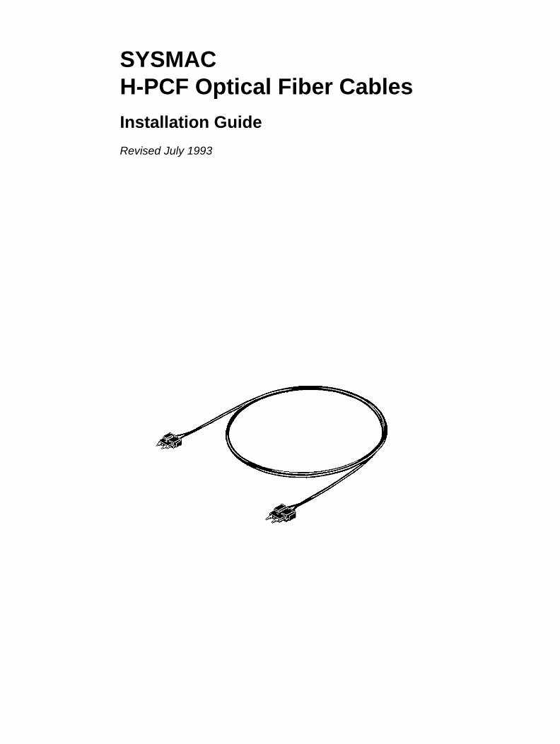
SYSMACH-PCF Optical Fiber Cables
Installation Guide
Revised July 1993

iv
v
Notice:OMRON products are manufactured for use according to proper procedures by a qualified operatorand only for the purposes described in this manual.
The following conventions are used to indicate and classify precautions in this manual. Always heedthe information provided with them. Failure to head precautions can result in injury to people or dam-age to the product.
DANGER! Indicates information that, if not heeded, is likely to result in loss of life or seriousinjury.
WARNING Indicates information that, if not heeded, could possibly result in loss of life orserious injury.
Caution Indicates information that, if not heeded, could result in relative serious or minorinjury, damage to the product, or faulty operation.
OMRON Product ReferencesAll OMRON products are capitalized in this manual. The word “Unit” is also capitalized when it refersto an OMRON product, regardless of whether or not it appears in the proper name of the product.
The abbreviation “Ch,” which appears in some displays and on some OMRON products, often means“word” and is abbreviated “Wd” in documentation in this sense.
The abbreviation “PC” means Programmable Controller and is not used as an abbreviation for any-thing else.
Visual AidsThe following headings appear in the left column of the manual to help you locate different types ofinformation.
Note Indicates information of particular interest for efficient and convenient operationof the product.
1, 2, 3... 1. Indicates lists of one sort or another, such as procedures, checklists, etc.
OMRON, 1989All rights reserved. No part of this publication may be reproduced, stored in a retrieval system, or transmitted, in anyform, or by any means, mechanical, electronic, photocopying, recording, or otherwise, without the prior written permis-sion of OMRON.
No patent liability is assumed with respect to the use of the information contained herein. Moreover, because OMRON isconstantly striving to improve its high-quality products, the information contained in this manual is subject to changewithout notice. Every precaution has been taken in the preparation of this manual. Nevertheless, OMRON assumes noresponsibility for errors or omissions. Neither is any liability assumed for damages resulting from the use of the informa-tion contained in this publication.

vi
TABLE OF CONTENTS
vii
SECTION 1Introduction 1. . . . . . . . . . . . . . . . . . . . . . . . . . . . . . . . . . . .
1-1 Introduction to H-PCF Optical Fiber Cables 2. . . . . . . . . . . . . . . . . . . . . . . . . . . . . . . . . . . 1-2 Features of H-PCF Optical Fiber 3. . . . . . . . . . . . . . . . . . . . . . . . . . . . . . . . . . . . . . . . . . . .
SECTION 2H-PCF Cord and Cable Specifications 7. . . . . . . . . . . . . . .
2-1 Component Materials and Dimensions 8. . . . . . . . . . . . . . . . . . . . . . . . . . . . . . . . . . . . . . . 2-2 Specifications 10. . . . . . . . . . . . . . . . . . . . . . . . . . . . . . . . . . . . . . . . . . . . . . . . . . . . . . . . . . . 2-3 Factory Inspection 12. . . . . . . . . . . . . . . . . . . . . . . . . . . . . . . . . . . . . . . . . . . . . . . . . . . . . . .
SECTION 3Connectors for H-PCF Optical Fibers 13. . . . . . . . . . . . . . .
3-1 Connectors 14. . . . . . . . . . . . . . . . . . . . . . . . . . . . . . . . . . . . . . . . . . . . . . . . . . . . . . . . . . . . . 3-2 Connector Components 16. . . . . . . . . . . . . . . . . . . . . . . . . . . . . . . . . . . . . . . . . . . . . . . . . . . 3-3 Connector Assembly 17. . . . . . . . . . . . . . . . . . . . . . . . . . . . . . . . . . . . . . . . . . . . . . . . . . . . . 3-4 Optical Power Testing 19. . . . . . . . . . . . . . . . . . . . . . . . . . . . . . . . . . . . . . . . . . . . . . . . . . . .
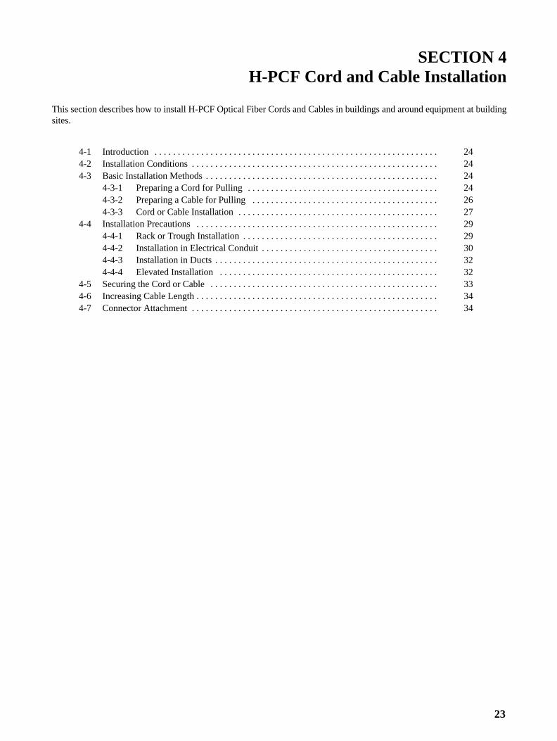
SECTION 4H-PCF Cord and Cable Installation 23. . . . . . . . . . . . . . . . .
4-1 Introduction 24. . . . . . . . . . . . . . . . . . . . . . . . . . . . . . . . . . . . . . . . . . . . . . . . . . . . . . . . . . . . 4-2 Installation Conditions 24. . . . . . . . . . . . . . . . . . . . . . . . . . . . . . . . . . . . . . . . . . . . . . . . . . . . 4-3 Basic Installation Methods 24. . . . . . . . . . . . . . . . . . . . . . . . . . . . . . . . . . . . . . . . . . . . . . . . . 4-4 Installation Precautions 29. . . . . . . . . . . . . . . . . . . . . . . . . . . . . . . . . . . . . . . . . . . . . . . . . . . 4-5 Securing the Cord or Cable 33. . . . . . . . . . . . . . . . . . . . . . . . . . . . . . . . . . . . . . . . . . . . . . . . 4-6 Increasing Cable Length 34. . . . . . . . . . . . . . . . . . . . . . . . . . . . . . . . . . . . . . . . . . . . . . . . . . 4-7 Connector Attachment 34. . . . . . . . . . . . . . . . . . . . . . . . . . . . . . . . . . . . . . . . . . . . . . . . . . . .
AppendicesA Standard Models 35. . . . . . . . . . . . . . . . . . . . . . . . . . . . . . . . . . . . . . . . . . . . . . . . . . . . . . . . . . .
Glossary 39. . . . . . . . . . . . . . . . . . . . . . . . . . . . . . . . . . . . . . . Index 41. . . . . . . . . . . . . . . . . . . . . . . . . . . . . . . . . . . . . . . . . .
Revision History 43. . . . . . . . . . . . . . . . . . . . . . . . . . . . . . . . .
ix
About this Manual:
This manual describes the installation of hard-clad PCF (H–PCF) Optical Fiber Cords and Cables andincludes the sections described below. Information concerning individual components of the SYSMACNET LINK, SYSMAC NET, SYSMAC BUS, SYSMAC BUS/2, and SYSMAC Host Link Systems can befound in their respective manuals.
Please read this manual carefully and be sure you understand the information provided before attemptingto install Optical Fiber Cords or Cables.
WARNING Failure to read and understand the information provided in this manual may result in personal injuryor death, damage to the product, or product failure. Please read each section in its entirety and besure you understand the information provided in the section and related sections before attemptingany of the procedures or operations given.
Section 1 introduces the special characteristics of Optical Fiber Cord and Cable and compares H-PCFoptical fiber to earlier varieties.
Section 2 describes the components of H-PCF Optical Fiber Cords and Cables and provides specifica-tions for the cords and cables.
Section 3 provides information on the dimensions, assembly, and testing of Optical Connectors used withH-PCF Optical Fiber Cords and Cables.
Section 4 describes how to install H-PCF Optical Fiber Cord and Cable in buildings and around equip-ment at building sites.
Appendix A provides ordering information for Optical Fiber Cords, Optical Fiber Cables, and relatedequipment.
1
SECTION 1Introduction
This section introduces the special characteristics of Optical Fiber Cords and Cables and compares H-PCF optical fiber toearlier varieties.
1-1 Introduction to H-PCF Optical Fiber Cables 2. . . . . . . . . . . . . . . . . . . . . . . . . . . . . . . . . . . . 1-2 Features of H-PCF Optical Fiber 3. . . . . . . . . . . . . . . . . . . . . . . . . . . . . . . . . . . . . . . . . . . . .
2
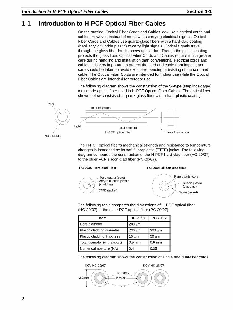
1-1 Introduction to H-PCF Optical Fiber CablesOn the outside, Optical Fiber Cords and Cables look like electrical cords andcables. However, instead of metal wires carrying electrical signals, OpticalFiber Cords and Cables use quartz-glass fibers with a hard-clad coating(hard acrylic fluoride plastic) to carry light signals. Optical signals travelthrough the glass fiber for distances up to 1 km. Though the plastic coatingprotects the glass fiber, Optical Fiber Cords and Cables require much greatercare during handling and installation than conventional electrical cords andcables. It is very important to protect the cord and cable from impact, andcare should be taken to avoid excessive bending or twisting of the cord andcable. The Optical Fiber Cords are intended for indoor use while the OpticalFiber Cables are intended for outdoor use.
The following diagram shows the construction of the SI-type (step index type)multimode optical fiber used in H-PCF Optical Fiber Cables. The optical fibershown below consists of a quartz-glass fiber with a hard plastic coating.
Core
Hard plastic
Light
Total reflection
Total reflectionH-PCF optical fiber Index of refraction
The H-PCF optical fiber’s mechanical strength and resistance to temperaturechanges is increased by its soft fluoroplastic (ETFE) jacket. The followingdiagram compares the construction of the H-PCF hard-clad fiber (HC-20/07)to the older PCF silicon-clad fiber (PC-20/07).
Pure quartz (core)Acrylic fluoride plastic(cladding)
ETFE (jacket)
HC-20/07 Hard-clad Fiber
Pure quartz (core)
Silicon plastic(cladding)
Nylon (jacket)
PC-20/07 silicon-clad fiber
The following table compares the dimensions of H-PCF optical fiber(HC-20/07) to the older PCF optical fiber (PC-20/07).
Item HC-20/07 PC-20/07
Core diameter 200 �m
Plastic cladding diameter 230 �m 300 �m
Plastic cladding thickness 15 �m 50 �m
Total diameter (with jacket) 0.5 mm 0.9 mm
Numerical aperture (NA) 0.4 0.35
The following diagram shows the construction of single and dual-fiber cords:
PVC
HC-20/07
DCV-HC-20/07CCV-HC-20/07
2.2 mm Kevlar
Introduction to H-PCF Optical Fiber Cables Section 1-1
3
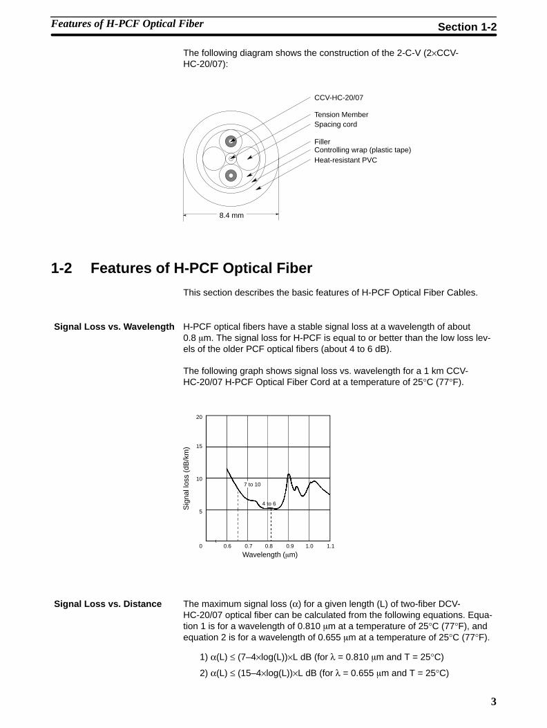
The following diagram shows the construction of the 2-C-V (2×CCV-HC-20/07):
Tension Member
CCV-HC-20/07
Spacing cord
FillerControlling wrap (plastic tape)Heat-resistant PVC
8.4 mm
1-2 Features of H-PCF Optical Fiber
This section describes the basic features of H-PCF Optical Fiber Cables.
H-PCF optical fibers have a stable signal loss at a wavelength of about0.8 �m. The signal loss for H-PCF is equal to or better than the low loss lev-els of the older PCF optical fibers (about 4 to 6 dB).
The following graph shows signal loss vs. wavelength for a 1 km CCV-HC-20/07 H-PCF Optical Fiber Cord at a temperature of 25°C (77°F).
Sig
nal l
oss
(dB
/km
)
Wavelength (�m)
20
15
10
0
5
0.6 0.7 0.8 0.9 1.0 1.1
7 to 10
4 to 6
The maximum signal loss (α) for a given length (L) of two-fiber DCV-HC-20/07 optical fiber can be calculated from the following equations. Equa-tion 1 is for a wavelength of 0.810 �m at a temperature of 25°C (77°F), andequation 2 is for a wavelength of 0.655 �m at a temperature of 25°C (77°F).
1) α(L) ≤ (7–4×log(L))×L dB (for λ = 0.810 �m and T = 25°C)
2) α(L) ≤ (15–4×log(L))×L dB (for λ = 0.655 �m and T = 25°C)
Signal Loss vs. Wavelength
Signal Loss vs. Distance
Features of H-PCF Optical Fiber Section 1-2
4
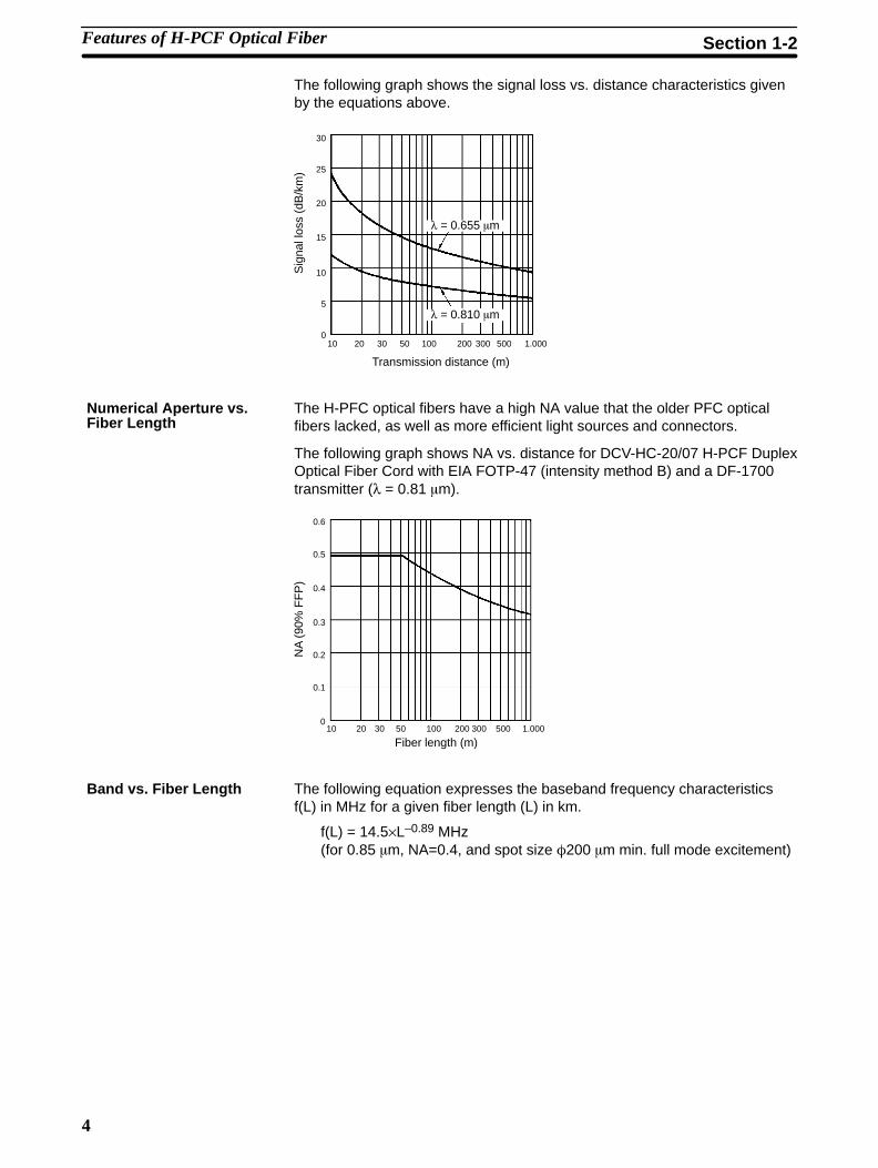
The following graph shows the signal loss vs. distance characteristics givenby the equations above.
Sig
nal l
oss
(dB
/km
)
Transmission distance (m)
30
25
20
10
5
0
15
10 20 30 50 100 200 300 500 1.000
λ = 0.810 �m
λ = 0.655 �m
The H-PFC optical fibers have a high NA value that the older PFC opticalfibers lacked, as well as more efficient light sources and connectors.
The following graph shows NA vs. distance for DCV-HC-20/07 H-PCF DuplexOptical Fiber Cord with EIA FOTP-47 (intensity method B) and a DF-1700transmitter (λ = 0.81 �m).
NA
(90
% F
FP
)
Fiber length (m)
0.6
0.5
0.4
0.3
0.2
0.1
010 20 30 50 100 200 300 500 1.000
The following equation expresses the baseband frequency characteristicsf(L) in MHz for a given fiber length (L) in km.
f(L) = 14.5×L–0.89 MHz(for 0.85 �m, NA=0.4, and spot size �200 �m min. full mode excitement)
Numerical Aperture vs.Fiber Length
Band vs. Fiber Length
Features of H-PCF Optical Fiber Section 1-2
5
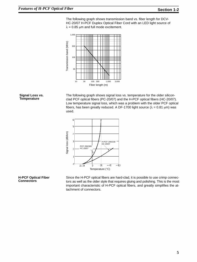
The following graph shows transmission band vs. fiber length for DCV-HC-20/07 H-PCF Duplex Optical Fiber Cord with an LED light source ofλ = 0.85 �m and full mode excitement.
Tran
smis
sion
ban
d (M
Hz)
Fiber length (m)
1,000
300
100
30
10 30 100 300 1,000 3,000
The following graph shows signal loss vs. temperature for the older silicon-clad PCF optical fibers (PC-20/07) and the H-PCF optical fibers (HC-20/07).Low temperature signal loss, which was a problem with the older PCF opticalfibers, has been greatly reduced. A DF-1700 light source (λ = 0.81 �m) wasused.
Sig
nal l
oss
(dB
/km
)
Temperature (°C)
PCF 200/300PC-20/07
H-PCF 200/230HC-20/07
Since the H-PCF optical fibers are hard-clad, it is possible to use crimp connec-tors as well as the older style that requires gluing and polishing. This is the mostimportant characteristic of H-PCF optical fibers, and greatly simplifies the at-tachment of connectors.
Signal Loss vs.Temperature
H-PCF Optical FiberConnectors
Features of H-PCF Optical Fiber Section 1-2
7
SECTION 2H-PCF Cord and Cable Specifications
This section describes the components of H-PCF Optical Fiber Cords and Cables and provides specifications for the cords andcables.
2-1 Component Materials and Dimensions 8. . . . . . . . . . . . . . . . . . . . . . . . . . . . . . . . . . . . . . . . 2-2 Specifications 10. . . . . . . . . . . . . . . . . . . . . . . . . . . . . . . . . . . . . . . . . . . . . . . . . . . . . . . . . . . . 2-3 Factory Inspection 12. . . . . . . . . . . . . . . . . . . . . . . . . . . . . . . . . . . . . . . . . . . . . . . . . . . . . . . .
8
2-1 Component Materials and DimensionsThese specifications apply to two-fiber H-PCF (hard plastic-clad optical fiber)Optical Fiber Cords and metallic-construction Optical Fiber Cables. Refer to Ap-pendix A Standard Models for ordering information.
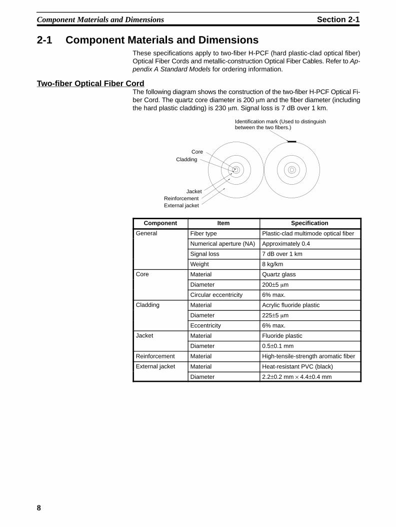
Two-fiber Optical Fiber CordThe following diagram shows the construction of the two-fiber H-PCF Optical Fi-ber Cord. The quartz core diameter is 200 �m and the fiber diameter (includingthe hard plastic cladding) is 230 �m. Signal loss is 7 dB over 1 km.
CoreCladding
JacketReinforcementExternal jacket
Identification mark (Used to distinguishbetween the two fibers.)
Component Item Specification
General Fiber type Plastic-clad multimode optical fiber
Numerical aperture (NA) Approximately 0.4
Signal loss 7 dB over 1 km
Weight 8 kg/km
Core Material Quartz glass
Diameter 200±5 �m
Circular eccentricity 6% max.
Cladding Material Acrylic fluoride plasticg
Diameter 225±5 �m
Eccentricity 6% max.
Jacket Material Fluoride plastic
Diameter 0.5±0.1 mm
Reinforcement Material High-tensile-strength aromatic fiber
External jacket Material Heat-resistant PVC (black)j
Diameter 2.2±0.2 mm × 4.4±0.4 mm
Component Materials and Dimensions Section 2-1
9
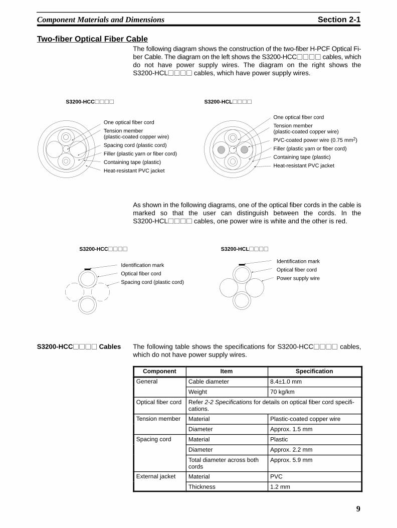
Two-fiber Optical Fiber CableThe following diagram shows the construction of the two-fiber H-PCF Optical Fi-ber Cable. The diagram on the left shows the S3200-HCC���� cables, whichdo not have power supply wires. The diagram on the right shows theS3200-HCL���� cables, which have power supply wires.
One optical fiber cord
Tension member(plastic-coated copper wire)
Spacing cord (plastic cord)
Filler (plastic yarn or fiber cord)
Containing tape (plastic)
Heat-resistant PVC jacket
One optical fiber cord
Tension member(plastic-coated copper wire)
PVC-coated power wire (0.75 mm2)
Filler (plastic yarn or fiber cord)
Containing tape (plastic)
Heat-resistant PVC jacket
S3200-HCC���� S3200-HCL����
As shown in the following diagrams, one of the optical fiber cords in the cable ismarked so that the user can distinguish between the cords. In theS3200-HCL���� cables, one power wire is white and the other is red.
Identification mark
Optical fiber cord
Spacing cord (plastic cord)
Identification mark
Optical fiber cord
Power supply wire
S3200-HCC���� S3200-HCL����
S3200-HCC���� Cables The following table shows the specifications for S3200-HCC���� cables,which do not have power supply wires.
Component Item Specification
General Cable diameter 8.4±1.0 mm
Weight 70 kg/km
Optical fiber cord Refer 2-2 Specifications for details on optical fiber cord specifi-cations.
Tension member Material Plastic-coated copper wire
Diameter Approx. 1.5 mm
Spacing cord Material Plasticp g
Diameter Approx. 2.2 mm
Total diameter across bothcords
Approx. 5.9 mm
External jacket Material PVCj
Thickness 1.2 mm
Component Materials and Dimensions Section 2-1
10
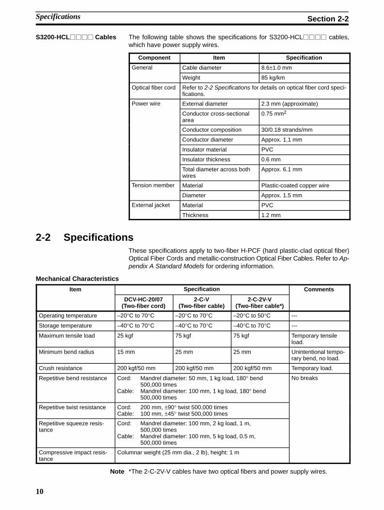
S3200-HCL���� Cables The following table shows the specifications for S3200-HCL���� cables,which have power supply wires.
Component Item Specification
General Cable diameter 8.6±1.0 mm
Weight 85 kg/km
Optical fiber cord Refer to 2-2 Specifications for details on optical fiber cord speci-fications.
Power wire External diameter 2.3 mm (approximate)
Conductor cross-sectionalarea
0.75 mm2
Conductor composition 30/0.18 strands/mm
Conductor diameter Approx. 1.1 mm
Insulator material PVC
Insulator thickness 0.6 mm
Total diameter across bothwires
Approx. 6.1 mm
Tension member Material Plastic-coated copper wire
Diameter Approx. 1.5 mm
External jacket Material PVCj
Thickness 1.2 mm
2-2 SpecificationsThese specifications apply to two-fiber H-PCF (hard plastic-clad optical fiber)Optical Fiber Cords and metallic-construction Optical Fiber Cables. Refer to Ap-pendix A Standard Models for ordering information.
Mechanical Characteristics
Item Specification Comments
DCV-HC-20/07(Two-fiber cord)
2-C-V(Two-fiber cable)
2-C-2V-V(Two-fiber cable*)
Operating temperature –20°C to 70°C –20°C to 70°C –20°C to 50°C ---
Storage temperature –40°C to 70°C –40°C to 70°C –40°C to 70°C ---
Maximum tensile load 25 kgf 75 kgf 75 kgf Temporary tensileload.
Minimum bend radius 15 mm 25 mm 25 mm Unintentional tempo-rary bend, no load.
Crush resistance 200 kgf/50 mm 200 kgf/50 mm 200 kgf/50 mm Temporary load.
Repetitive bend resistance Cord: Mandrel diameter: 50 mm, 1 kg load, 180° bend 500,000 times
Cable: Mandrel diameter: 100 mm, 1 kg load, 180° bend 500,000 times
No breaks
Repetitive twist resistance Cord: 200 mm, ±90° twist 500,000 timesCable: 100 mm, ±45° twist 500,000 times
Repetitive squeeze resis-tance
Cord: Mandrel diameter: 100 mm, 2 kg load, 1 m, 500,000 times
Cable: Mandrel diameter: 100 mm, 5 kg load, 0.5 m, 500,000 times
Compressive impact resis-tance
Columnar weight (25 mm dia., 2 lb), height: 1 m
Note *The 2-C-2V-V cables have two optical fibers and power supply wires.
Specifications Section 2-2

11
Transmission Characteristics
Item Ambienttemp.
Wavelength Fiber length Specification
Signal loss 25°C l=0.81 �m (DF-2700 LED) Lf=1 km 7 dB/km max.g � ( )
l=0.85 �m (DF-2200 LED) 0.1 ≤ Lf ≤ 1km
7–4 × log(Lf) dB/km max.
l=0.655 �m (DF-2701LED)
Lf=1 km 15 dB/km max.� (LED)
0.1 ≤ Lf ≤ 1km
15–4 × log(Lf) dB/km max.
Transmissionband
--- l=0.85 �m LED Lf=1 km Approx. 14 MHz
Signal loss at lowtemp.
–20°C l=0.81 �m Lf=1 km Up to two times the signal loss (in dB) at25°C.
Signal loss athigh temp.
25°C Up to 1.5 times the initial signal loss (in dB)after 1,000 hrs at 70°C.g p
–20°C(exam-ple)
Up to 1.5 times the initial signal loss (in dB)after 1,000 hrs at 70°C.
Signal loss athigh temp. andhumidity
25°C Up to 1.5 times the initial signal loss (in dB)after 1,000 hrs at 70°C and 95%.
Crimp Connector Specifications
Item Specification Comments
Increase in signal loss (dB) due tocrimp connection
Approx. 1.5 times higher with crimp con-nection.
λ=0.81 �m
Maximum tensile load 5 kgf Unintentional temporary tensionbetween the connector and cordat 25°C.
Signal loss (dB) at high temp. ±1.5 times the initial signal loss (in dB) af-ter 1,000 hrs at 70°C.
Signal loss:The increase in signal loss (dB)
d t th i iti l l ithExpansion at high temp. ±15 �m protrusion after 1,000 hrs at 70°C.
g ( )compared to the initial value withλ=0.81 �m and T=25°C at both
Signal loss (dB) at high temp. and hu-midity
±1.5 times the initial signal loss (in dB) af-ter 1,000 hrs at 70°C and 95%.
λ=0.81 �m and T=25°C at bothends.
Expansion:Expansion at high temp. and humidity ±15 �m protrusion after 1,000 hrs at 70°C
and 95%.
Expansion:The change in the protrusion be-tween the core and ferrule tipcompared to the initial value
Signal loss (dB) from 100 suddentemperature changes (70°C/–40°C)
±1.5 times the initial signal loss (in dB) af-ter 1,000 hrs at 70°C and 95%.
compared to the initial value.
Expansion from 100 sudden tempera-ture changes (70°C/–40°C)
±15 �m protrusion after 1,000 hrs at 70°Cand 95%.
Electrical Characteristics
Item Specification
Cross sectional area of power supply wire’s con-ductor
0.75 mm2
Maximum conductor resistance 26.1 �/km (at 20°C)
Dielectric strength 1000 V for 1 minute
Minimum insulator resistance 5 M� km (at 20°C)
Maximum current 5 A/conductor
Specifications Section 2-2
12
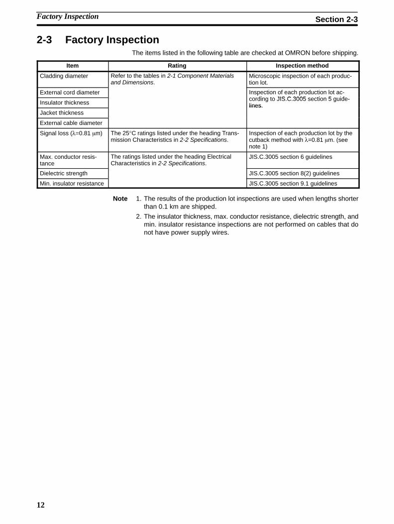
2-3 Factory InspectionThe items listed in the following table are checked at OMRON before shipping.
Item Rating Inspection method
Cladding diameter Refer to the tables in 2-1 Component Materialsand Dimensions.
Microscopic inspection of each produc-tion lot.
External cord diameter Inspection of each production lot ac-di t JIS C 3005 ti 5 id
Insulator thickness
p pcording to JIS.C.3005 section 5 guide-lines.
Jacket thicknesslines.
External cable diameter
Signal loss (λ=0.81 �m) The 25°C ratings listed under the heading Trans-mission Characteristics in 2-2 Specifications.
Inspection of each production lot by thecutback method with λ=0.81 �m. (seenote 1)
Max. conductor resis-tance
The ratings listed under the heading ElectricalCharacteristics in 2-2 Specifications.
JIS.C.3005 section 6 guidelines
Dielectric strength
p
JIS.C.3005 section 8(2) guidelines
Min. insulator resistance JIS.C.3005 section 9.1 guidelines
Note 1. The results of the production lot inspections are used when lengths shorterthan 0.1 km are shipped.
2. The insulator thickness, max. conductor resistance, dielectric strength, andmin. insulator resistance inspections are not performed on cables that donot have power supply wires.
Factory Inspection Section 2-3
13
SECTION 3Connectors for H-PCF Optical Fibers
This section provides information on the dimensions, assembly, and testing of Optical Connectors used with H-PCF OpticalFiber Cords and Cables.
3-1 Connectors 14. . . . . . . . . . . . . . . . . . . . . . . . . . . . . . . . . . . . . . . . . . . . . . . . . . . . . . . . . . . . . . 3-2 Connector Components 16. . . . . . . . . . . . . . . . . . . . . . . . . . . . . . . . . . . . . . . . . . . . . . . . . . . . 3-3 Connector Assembly 17. . . . . . . . . . . . . . . . . . . . . . . . . . . . . . . . . . . . . . . . . . . . . . . . . . . . . . 3-4 Optical Power Testing 19. . . . . . . . . . . . . . . . . . . . . . . . . . . . . . . . . . . . . . . . . . . . . . . . . . . . .
3-4-1 Optical Power Testers 19. . . . . . . . . . . . . . . . . . . . . . . . . . . . . . . . . . . . . . . . . . . . . . 3-4-2 Optical Power Testing Tools 19. . . . . . . . . . . . . . . . . . . . . . . . . . . . . . . . . . . . . . . . . 3-4-3 Optical Power Testing Methods 20. . . . . . . . . . . . . . . . . . . . . . . . . . . . . . . . . . . . . . .
14
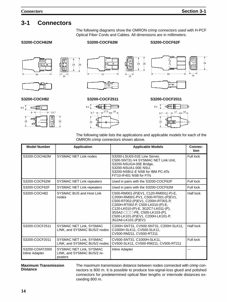
3-1 ConnectorsThe following diagrams show the OMRON crimp connectors used with H-PCFOptical Fiber Cords and Cables. All dimensions are in millimeters.
S3200-COCH62M S3200-COCF62M S3200-COCF62F
5410
23 26
5713
23 25
6414
24
S3200-COCH82 S3200-COCF2511 S3200-COCF2011
8.5
8 13.7
22
1417.56.7
8.2
22
8.2
6.717 14
2119
The following table lists the applications and applicable models for each of theOMRON crimp connectors shown above.
Model Number Application Applicable Models Connec-tion
S3200-COCH62M SYSMAC NET Link nodes S3200-LSU03-01E Line Server,C500-SNT31-V4 SYSMAC NET Link Unit,S3200-NSUG4-00E Bridge,S3200-NSUA1-00E NSU,S3200-NSB11-E NSB for IBM PC-ATsFIT10-IF401 NSB for FITs
Full lock
S3200-COCF62M SYSMAC NET Link repeaters Used in pairs with the S3200-COCF62F Full lock
S3200-COCF62F SYSMAC NET Link repeaters Used in pairs with the S3200-COCF62M Full lock
S3200-COCH82 SYSMAC BUS and Host Linknodes
C500-RM001-(P)EV1, C120-RM001(-P)-E,C200H-RM001-PV1, C500-RT001-(P)EV1,C500-RT002-(P)EV1, C200H-RT001-P,C200H-RT002-P, C500-LK010-(P)-E,C120-LK010-(P)-E, 3G2C7-LK011-(P),3G5A2-���-PE, C500-LK103-(P),C500-LK101-(P)EV1, C200H-LK101-P, 3G2A6-LK101-(P)EV1
Half lock
S3200-COCF2511 SYSMAC NET Link, SYSMACLINK, and SYSMAC BUS/2 nodes
C200H-SNT31, CV500-SNT31, C200H-SLK11,C1000H-SLK11, CV500-SLK11,CV500-RM211, CV500-RT211
Half lock
S3200-COCF2011 SYSMAC NET Link, SYSMACLINK, and SYSMAC BUS/2 nodes
CV500-SNT31, C1000H-SLK11,CV500-SLK11, CV500-RM211, CV500-RT211
Full lock
S3200-COIAT2000Inline Adapter
SYSMAC NET Link, SYSMACLINK, and SYSMAC BUS/2 re-peaters
Inline Adapter ---
The maximum transmission distance between nodes connected with crimp con-nectors is 800 m. It is possible to produce low-signal-loss glued and polishedconnectors for predetermined optical fiber lengths or internode distances ex-ceeding 800 m.
Maximum TransmissionDistance
Connectors Section 3-1
15
Applicable Connectors The following table lists the Units that can use crimp connectors and their appli-cable connectors.
Model Connector
S3200-LSU03-01E S3200-COCH62M
S3200-NSUG4-00E S3200-COCH62M
S3200-NSUA1-00E S3200-COCH62M
S3200-NSB11-E S3200-COCH62M
C500-SNT31-V4 S3200-COCH62M
C500-RM001-(P)EV1 S3200-COCH82
C500-RT001-(P)EV1 S3200-COCH82
C500-RT002-(P)EV1 S3200-COCH82
C500-LK010-(P)-E S3200-COCH82
C500-LK103-(P) S3200-COCH82
C500-LK101-(P)EV1 S3200-COCH82
C200H-RM001-PV1 S3200-COCH82
C200H-RT001-P S3200-COCH82
C200H-RT002-P S3200-COCH82
3G2C7-LK011-(P) S3200-COCH82
C200H-LK101-P S3200-COCH82
C200H-SNT31 S3200-COCF2511
C200H-SLK11 S3200-COCF2511
C120-RM001(-P)-E S3200-COCH82
C120-LK010-(P)-E S3200-COCH82
3G2A6-LK101-(P)EV1 S3200-COCH82
CV500-SNT31 S3200-COCF2511S3200-COCF2011
CV500-SLK11 S3200-COCF2511S3200-COCF2011
CV500-RM211 S3200-COCF2511S3200-COCF2011
CV500-RT211 S3200-COCF2511S3200-COCF2011
C1000H-SLK11 S3200-COCF2511S3200-COCF2011
3G5A2-���-PE S3200-COCH82
FIT10-IF401 S3200-COCH62M
Connectors Section 3-1
16
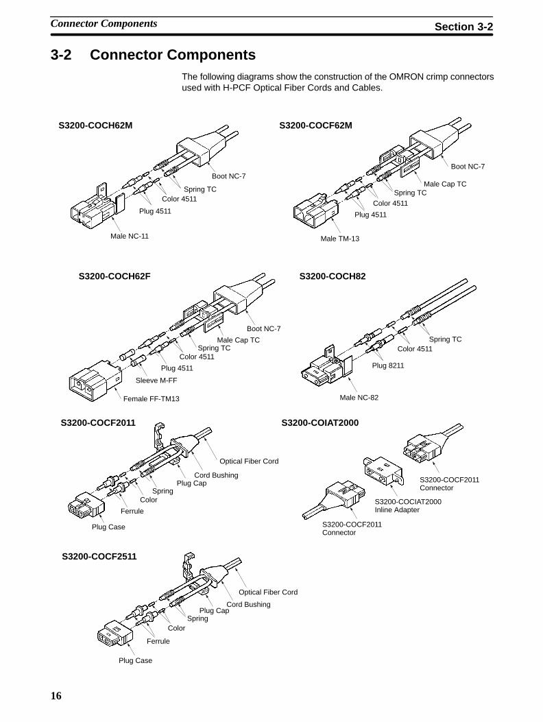
3-2 Connector ComponentsThe following diagrams show the construction of the OMRON crimp connectorsused with H-PCF Optical Fiber Cords and Cables.
S3200-COCH62M S3200-COCF62M
Male NC-11
Plug 4511
Color 4511Spring TC
Boot NC-7
Male TM-13
Plug 4511
Color 4511
Spring TC
Boot NC-7
Male Cap TC
S3200-COCH62F S3200-COCH82
Female FF-TM13
Plug 4511
Color 4511Spring TC
Boot NC-7
Male NC-82
Plug 8211
Color 4511Spring TC
Sleeve M-FF
Male Cap TC
S3200-COCF2011 S3200-COIAT2000
Plug Case
Ferrule
ColorSpring
Plug Cap S3200-COCF2011Connector
Cord Bushing
Optical Fiber Cord
S3200-COCIAT2000Inline Adapter
S3200-COCF2011Connector
S3200-COCF2511
Plug Case
Ferrule
ColorSpring
Plug CapCord Bushing
Optical Fiber Cord
Connector Components Section 3-2
17
3-3 Connector AssemblyThe specialized connector assembly tools needed to attach connectors to theH-PCF Optical Fiber Cord or Cable on site must be purchased separately. All ofthe required tools are included in the Optical Connector Assembly Tool Kit in acompact carrying case. Refer to Appendix A Standard Models for ordering in-formation.
In the past, attaching connectors to the optical fiber required time-consuminggluing and polishing, but crimp connectors can be attached quickly and easilyusing a ferrule crimper and optical fiber cutter. Refer to 3-4 Optical Power Test-ing for details on testing light transmission through the connector/fiber junctionwith an Optical Power Tester.
Connector Assembly Section 3-3
18
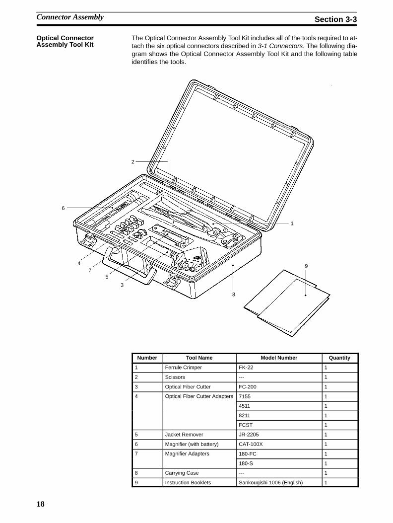
The Optical Connector Assembly Tool Kit includes all of the tools required to at-tach the six optical connectors described in 3-1 Connectors. The following dia-gram shows the Optical Connector Assembly Tool Kit and the following tableidentifies the tools.
2
6
47
5
3
8
1
9
Number Tool Name Model Number Quantity
1 Ferrule Crimper FK-22 1
2 Scissors --- 1
3 Optical Fiber Cutter FC-200 1
4 Optical Fiber Cutter Adapters 7155 1p p
4511 1
8211 1
FCST 1
5 Jacket Remover JR-2205 1
6 Magnifier (with battery) CAT-100X 1
7 Magnifier Adapters 180-FC 1g p
180-S 1
8 Carrying Case --- 1
9 Instruction Booklets Sankougishi 1006 (English) 1
Optical ConnectorAssembly Tool Kit
Connector Assembly Section 3-3
19
3-4 Optical Power Testing
3-4-1 Optical Power TestersThe Optical Power Testers and applicable units/boards are listed in the followingtable. One of the Master Fiber Sets listed in the next table is needed to test lightoutput with an Optical Power Tester Set.
Power TesterSet
Head Unit Applicable Unit/Board Applicable Optical Connector
S3200-CAT3200 S3200-CAT3202 C500-SNT31-V4, SYSMAC NET Linknodes
S3200-COCH62M, S3200-COCF62M,S3200-COCH62F
S3200-CAT2000 S3200-CAT2002 C200H-SNT31, CV500-SNT31,SYSMAC NET Link nodes
S3200-COCF2511, S3200-COCF2011
S3200-CAT2700 S3200-CAT2702 C200H-SLK11, C1000H-SLK11,CV500-SLK11, CV500-RM211,CV500-RT211
S3200-COCF2511, S3200-COCF2011
S3200-CAT2820 S3200-CAT2822 C500-RM001-(P)EV1, and other C-seriesHost Link, Optical Remote I/O, and I/OLink Units
S3200-COCH82
Note 1. All parts in the Power Tester Sets are compatible except the Head Units.
2. Refer to the table on page 15 for a complete list of units, boards, and theirapplicable Optical Connectors.
Master Fiber Sets A Master Fiber Set is needed when testing light output with an Optical PowerTester Set. The required Master Fiber Set depends on the Head Unit, as shownin the following table.
Head Unit Set Master Fiber Set
S3200-CAT3202 S3200-CAT3201
S3200-CAT2002 S3200-CAT2001H
S3200-CAT2702
S3200-CAT2822 S3200-CAT2821
Refer to the Master Fiber Set’s instruction booklet for details on using the MasterFiber Set.
3-4-2 Optical Power Testing ToolsUse the S3200-CAT2000 or S3200-CAT2700 Optical Power Tester Set to testlight transmission through the connector/fiber junction.
The following tables provide information on the Optical Power Tester Sets andHead Unit Sets.
Optical PowerTester Set
Head Unit Set Wave-length
Applicable Optical Module Applicable Optical Connec-tors
S3200-CAT2000 S3200-CAT2002 850 nm DF-1100DF-2100DF-2200
CF-2001H,S3200-COCF2011CF-2501H,S3200-COCF2511
S3200-CAT2700 S3200-CAT2702 810 nm DF-1700, TODX294 (OMRON)DF-1800DF-2700DF-2800
CF-2001H,S3200-COCF2011CF-2501H,S3200-COCF2511
Optical Power Tester Setand Head Unit Set
Optical Power Testing Section 3-4
20
The following table lists the component parts of the Optical Power Tester Setsand Head Unit Sets.
Component Optical Power Tester Set Head Unit Setp
S3200-CAT2000 S3200-CAT2700 S3200-CAT2002 S3200-CAT2702
Main Unit Model 205 Model 205 --- ---
Connector Adapter 180-HTL 180-HTL 180-HTL 180-HTL
Light Source 310-085CF (yellow la-bel)
310-081CF (orange la-bel)
310-085CF (yellow la-bel)
310-081CF (orange la-bel)
AC Adapter DP-1005 DP-1005 --- ---
Instruction Booklets Higishi 1939 (English) Higishi 1939 (English) Higishi 1939 (English) Higishi 1939 (English)
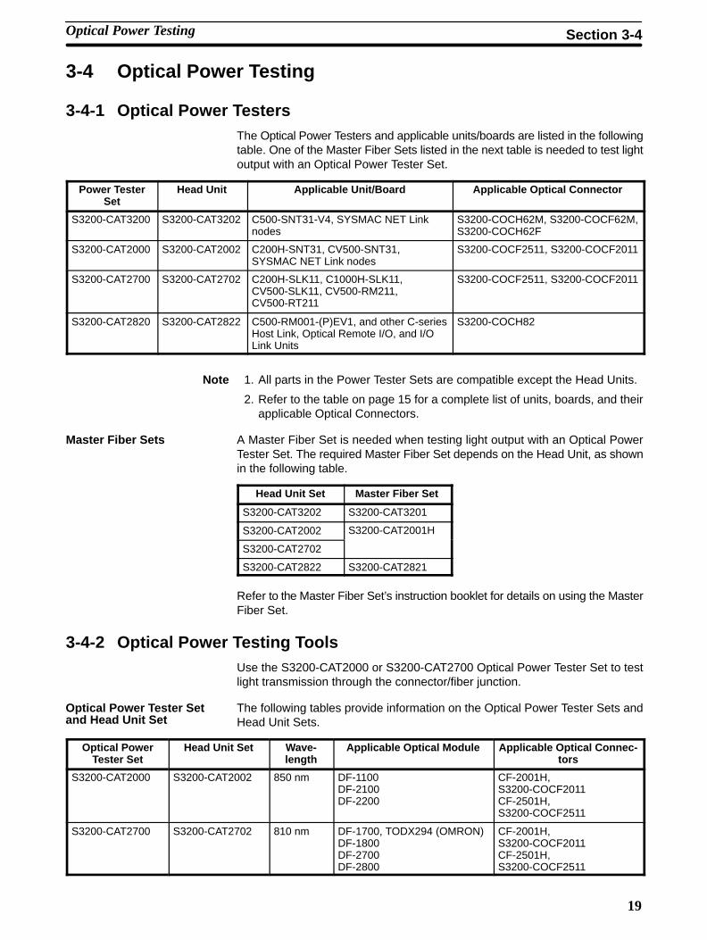
The following diagrams show the Power Tester Main Unit, the ConnectorAdapter (transmitter and receiver), and the Light Source.
Power Tester Main Unit Connector Adapter Light Source
Master Fiber Set The S3200-CAT2001H Master Fiber Set contains standard optical fibers thatare used in conjunction with the Optical Power Tester Sets when measuring opti-cal characteristics. Components of the S3200-CAT2001H Master Fiber Set arelisted in the following table.
Component Model Number Quantity
2001-MM-1 Master Fiber (see note) DCV-HC-20/07 1 m × 2
Inline Adapter IAT-2000 1
Case --- 1
Note These optical fibers are sorted for use as master fibers.
3-4-3 Optical Power Testing Methods
The light transmitted through a cable with optical connectors or inline adaptersshould satisfy the ratings given later in this section. The ratings use the value af,which can be calculated from the length of the optical fiber (L), as shown in thefollowing table.
Total Fiber Length (L) af
0.1 km< L ≤ 1 km (7–4 × log L) × L
L ≤ 0.1 km 1.1
Optical Power Testing Section 3-4
21
The amount of light transmitted through an optical fiber with crimp connectors atboth ends should satisfy the ratings given in the following table. The maximumtransmission distance for this configuration is 800 m.
Crimp Connector Crimp Connector
Light Path Rating
OPT LED (see note 1) → Master Fiber → Light Meter (measuring P0 dBm) ---
OPT LED → Test Fiber (see note 2) → Light Meter (measuring P1 dBm) P0 – P1 ≤ af + 1.5 dB
OPT LED → Test Fiber → Inline Adapter (see note 3) → Master Fiber → Light Meter(measuring P2 dBm) (see note 4)
P0 – P2 ≤ af + 3.5 dB
Note 1. The term OPT LED refers to an Optical Power Tester LED light source.
2. The term Test Fiber refers to an optical fiber with crimp connectors(S3200-COCF2011 and/or S3200-COCF2511) on both ends.
3. An S3200-COIAT2000 Inline Adapter.
4. It is not necessary to measure P2 when an Inline Adapter is not used.
The amount of light transmitted through two optical fibers attached by an InlineAdapter should satisfy the ratings given in the following table. Each optical fiberhas a crimp connector on just one end and this end is attached to the InlineAdapter. The maximum transmission distance for this configuration is 200 m.
Crimp Connector Crimp Connector
Inline Adapter
Light Path Rating
OPT LED (see note 1) → Master Fiber → Light Meter (measuring P0 dBm) ---
OPT LED → Test Fiber (see note 2) → Inline Adapter (see note 3) → Test Fiber → LightMeter (measuring P1 dBm)
P0 – P1 ≤ af + 7.1 dB
Note 1. The term OPT LED refers to an Optical Power Tester LED light source.
2. The term Test Fiber refers to an optical fiber with a crimp connector(S3200-COCF2011 or S3200-COCF2511) on the end connected to the In-line Adapter.
3. An S3200-COIAT2000 Inline Adapter.
Testing Optical Fibers withTwo Crimp Connectors
Testing Optical FibersLinked by an Inline Adapter
Optical Power Testing Section 3-4
23
SECTION 4H-PCF Cord and Cable Installation
This section describes how to install H-PCF Optical Fiber Cords and Cables in buildings and around equipment at buildingsites.
4-1 Introduction 24. . . . . . . . . . . . . . . . . . . . . . . . . . . . . . . . . . . . . . . . . . . . . . . . . . . . . . . . . . . . . 4-2 Installation Conditions 24. . . . . . . . . . . . . . . . . . . . . . . . . . . . . . . . . . . . . . . . . . . . . . . . . . . . . 4-3 Basic Installation Methods 24. . . . . . . . . . . . . . . . . . . . . . . . . . . . . . . . . . . . . . . . . . . . . . . . . .
4-3-1 Preparing a Cord for Pulling 24. . . . . . . . . . . . . . . . . . . . . . . . . . . . . . . . . . . . . . . . . 4-3-2 Preparing a Cable for Pulling 26. . . . . . . . . . . . . . . . . . . . . . . . . . . . . . . . . . . . . . . . 4-3-3 Cord or Cable Installation 27. . . . . . . . . . . . . . . . . . . . . . . . . . . . . . . . . . . . . . . . . . .
4-4 Installation Precautions 29. . . . . . . . . . . . . . . . . . . . . . . . . . . . . . . . . . . . . . . . . . . . . . . . . . . . 4-4-1 Rack or Trough Installation 29. . . . . . . . . . . . . . . . . . . . . . . . . . . . . . . . . . . . . . . . . . 4-4-2 Installation in Electrical Conduit 30. . . . . . . . . . . . . . . . . . . . . . . . . . . . . . . . . . . . . . 4-4-3 Installation in Ducts 32. . . . . . . . . . . . . . . . . . . . . . . . . . . . . . . . . . . . . . . . . . . . . . . . 4-4-4 Elevated Installation 32. . . . . . . . . . . . . . . . . . . . . . . . . . . . . . . . . . . . . . . . . . . . . . .
4-5 Securing the Cord or Cable 33. . . . . . . . . . . . . . . . . . . . . . . . . . . . . . . . . . . . . . . . . . . . . . . . . 4-6 Increasing Cable Length 34. . . . . . . . . . . . . . . . . . . . . . . . . . . . . . . . . . . . . . . . . . . . . . . . . . . . 4-7 Connector Attachment 34. . . . . . . . . . . . . . . . . . . . . . . . . . . . . . . . . . . . . . . . . . . . . . . . . . . . .
24
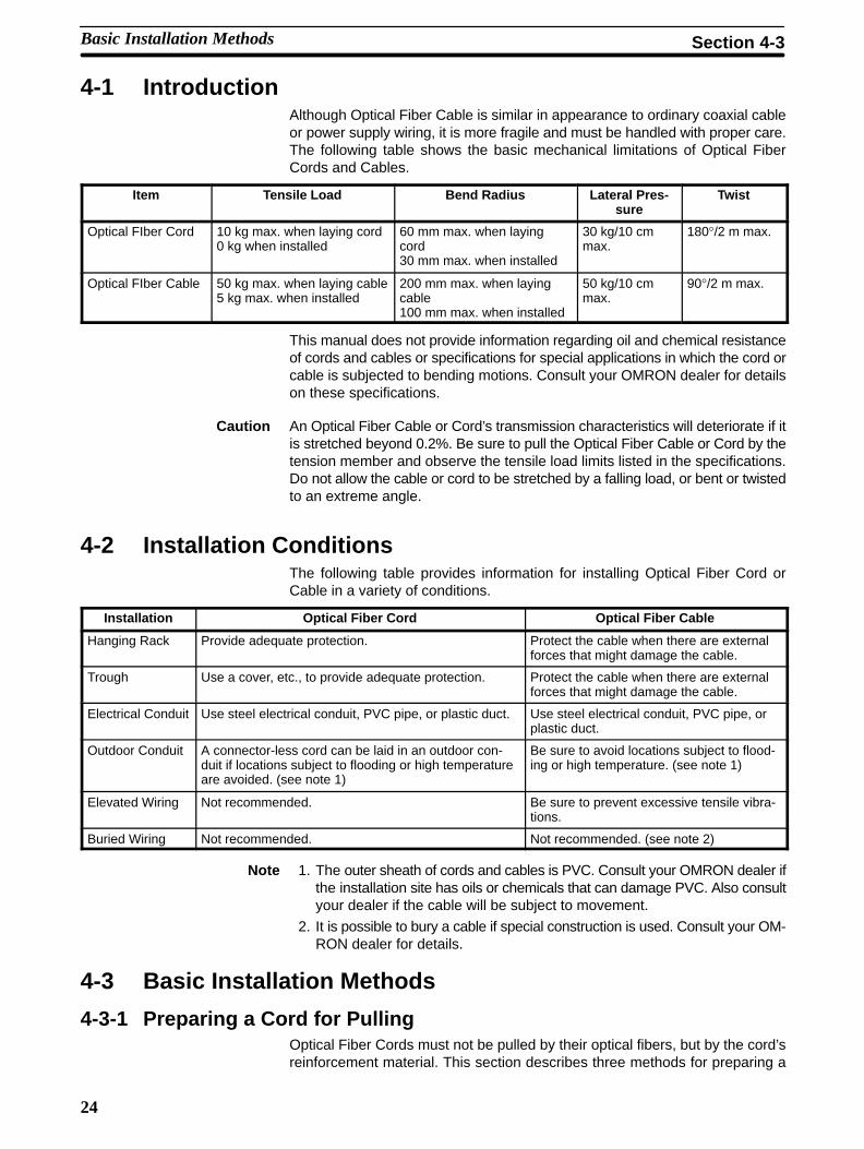
4-1 IntroductionAlthough Optical Fiber Cable is similar in appearance to ordinary coaxial cableor power supply wiring, it is more fragile and must be handled with proper care.The following table shows the basic mechanical limitations of Optical FiberCords and Cables.
Item Tensile Load Bend Radius Lateral Pres-sure
Twist
Optical FIber Cord 10 kg max. when laying cord0 kg when installed
60 mm max. when layingcord30 mm max. when installed
30 kg/10 cmmax.
180°/2 m max.
Optical FIber Cable 50 kg max. when laying cable5 kg max. when installed
200 mm max. when layingcable100 mm max. when installed
50 kg/10 cmmax.
90°/2 m max.
This manual does not provide information regarding oil and chemical resistanceof cords and cables or specifications for special applications in which the cord orcable is subjected to bending motions. Consult your OMRON dealer for detailson these specifications.
Caution An Optical Fiber Cable or Cord’s transmission characteristics will deteriorate if itis stretched beyond 0.2%. Be sure to pull the Optical Fiber Cable or Cord by thetension member and observe the tensile load limits listed in the specifications.Do not allow the cable or cord to be stretched by a falling load, or bent or twistedto an extreme angle.
4-2 Installation ConditionsThe following table provides information for installing Optical Fiber Cord orCable in a variety of conditions.
Installation Optical Fiber Cord Optical Fiber Cable
Hanging Rack Provide adequate protection. Protect the cable when there are externalforces that might damage the cable.
Trough Use a cover, etc., to provide adequate protection. Protect the cable when there are externalforces that might damage the cable.
Electrical Conduit Use steel electrical conduit, PVC pipe, or plastic duct. Use steel electrical conduit, PVC pipe, orplastic duct.
Outdoor Conduit A connector-less cord can be laid in an outdoor con-duit if locations subject to flooding or high temperatureare avoided. (see note 1)
Be sure to avoid locations subject to flood-ing or high temperature. (see note 1)
Elevated Wiring Not recommended. Be sure to prevent excessive tensile vibra-tions.
Buried Wiring Not recommended. Not recommended. (see note 2)
Note 1. The outer sheath of cords and cables is PVC. Consult your OMRON dealer ifthe installation site has oils or chemicals that can damage PVC. Also consultyour dealer if the cable will be subject to movement.
2. It is possible to bury a cable if special construction is used. Consult your OM-RON dealer for details.
4-3 Basic Installation Methods
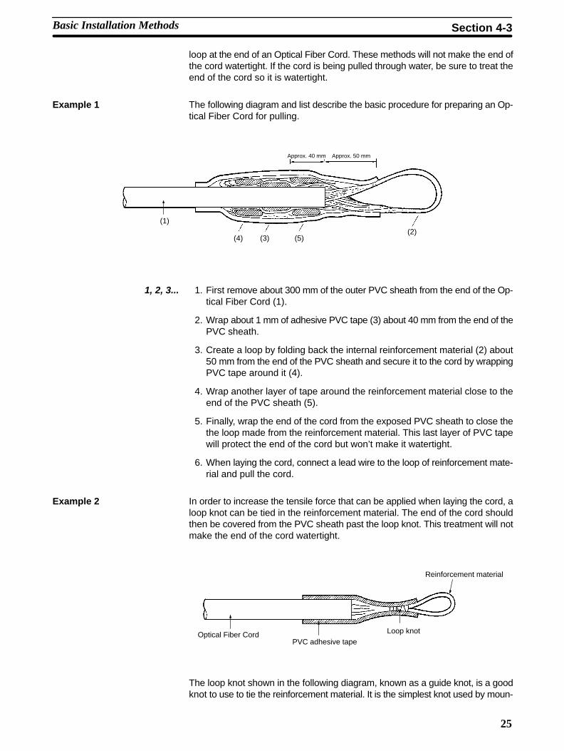
4-3-1 Preparing a Cord for PullingOptical Fiber Cords must not be pulled by their optical fibers, but by the cord’sreinforcement material. This section describes three methods for preparing a
Basic Installation Methods Section 4-3
25
loop at the end of an Optical Fiber Cord. These methods will not make the end ofthe cord watertight. If the cord is being pulled through water, be sure to treat theend of the cord so it is watertight.
Example 1 The following diagram and list describe the basic procedure for preparing an Op-tical Fiber Cord for pulling.
(1)
(4) (3) (5)(2)
Approx. 40 mm Approx. 50 mm
1, 2, 3... 1. First remove about 300 mm of the outer PVC sheath from the end of the Op-tical Fiber Cord (1).
2. Wrap about 1 mm of adhesive PVC tape (3) about 40 mm from the end of thePVC sheath.
3. Create a loop by folding back the internal reinforcement material (2) about50 mm from the end of the PVC sheath and secure it to the cord by wrappingPVC tape around it (4).
4. Wrap another layer of tape around the reinforcement material close to theend of the PVC sheath (5).
5. Finally, wrap the end of the cord from the exposed PVC sheath to close thethe loop made from the reinforcement material. This last layer of PVC tapewill protect the end of the cord but won’t make it watertight.
6. When laying the cord, connect a lead wire to the loop of reinforcement mate-rial and pull the cord.
Example 2 In order to increase the tensile force that can be applied when laying the cord, aloop knot can be tied in the reinforcement material. The end of the cord shouldthen be covered from the PVC sheath past the loop knot. This treatment will notmake the end of the cord watertight.
Optical Fiber CordPVC adhesive tape
Loop knot
Reinforcement material
The loop knot shown in the following diagram, known as a guide knot, is a goodknot to use to tie the reinforcement material. It is the simplest knot used by moun-
Basic Installation Methods Section 4-3
26
tain climbers when the rope is tied around the body and can be mastered quicklyby beginners.
Example 3 If the cord is being pulled through a relatively large conduit, a cord can be foldedback onto itself and taped to make a loop. If this method is used, the end of thecord which was folded will be damaged and cannot be used to transmit light. Cutoff the end of the cord after it has been installed.
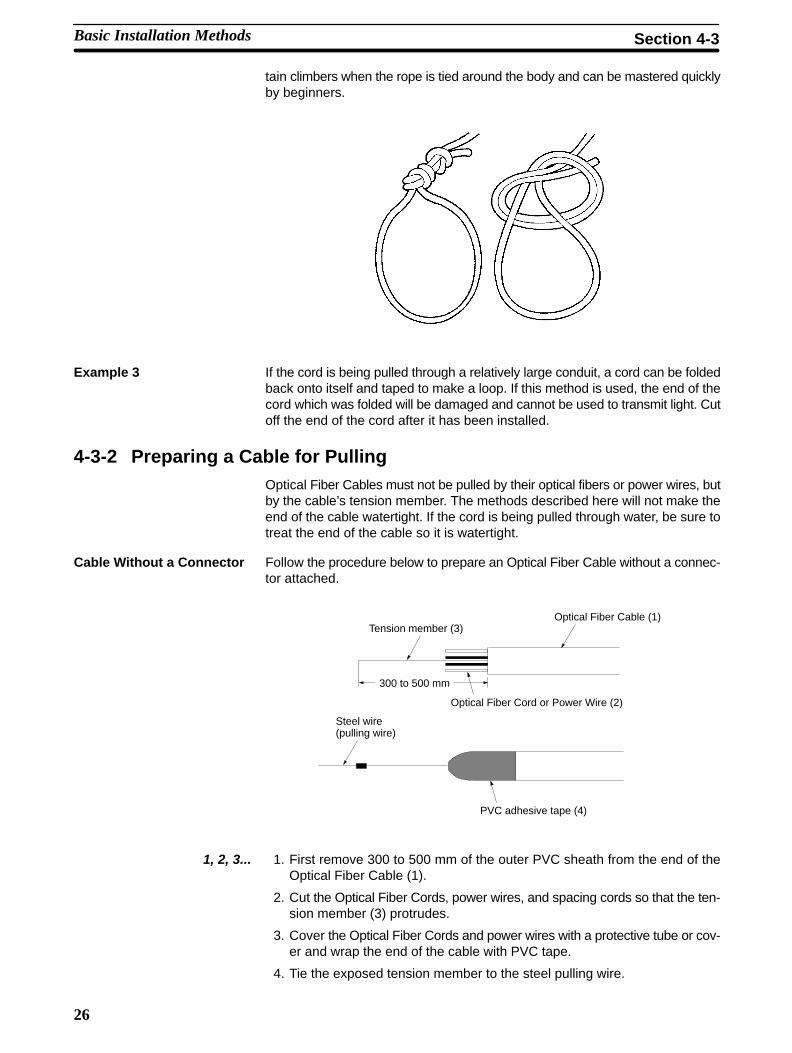
4-3-2 Preparing a Cable for PullingOptical Fiber Cables must not be pulled by their optical fibers or power wires, butby the cable’s tension member. The methods described here will not make theend of the cable watertight. If the cord is being pulled through water, be sure totreat the end of the cable so it is watertight.
Cable Without a Connector Follow the procedure below to prepare an Optical Fiber Cable without a connec-tor attached.
Tension member (3)Optical Fiber Cable (1)
Optical Fiber Cord or Power Wire (2)
Steel wire(pulling wire)
PVC adhesive tape (4)
300 to 500 mm
1, 2, 3... 1. First remove 300 to 500 mm of the outer PVC sheath from the end of theOptical Fiber Cable (1).
2. Cut the Optical Fiber Cords, power wires, and spacing cords so that the ten-sion member (3) protrudes.
3. Cover the Optical Fiber Cords and power wires with a protective tube or cov-er and wrap the end of the cable with PVC tape.
4. Tie the exposed tension member to the steel pulling wire.
Basic Installation Methods Section 4-3
27
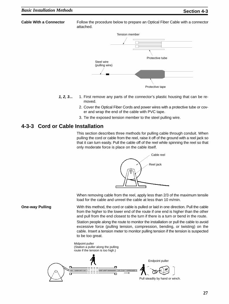
Cable With a Connector Follow the procedure below to prepare an Optical Fiber Cable with a connectorattached.
Tension member
Protective tubeSteel wire(pulling wire)
Protective tape
1, 2, 3... 1. First remove any parts of the connector’s plastic housing that can be re-moved.
2. Cover the Optical Fiber Cords and power wires with a protective tube or cov-er and wrap the end of the cable with PVC tape.
3. Tie the exposed tension member to the steel pulling wire.
4-3-3 Cord or Cable InstallationThis section describes three methods for pulling cable through conduit. Whenpulling the cord or cable from the reel, raise it off of the ground with a reel jack sothat it can turn easily. Pull the cable off of the reel while spinning the reel so thatonly moderate force is place on the cable itself.
Cable reel
Reel jack
When removing cable from the reel, apply less than 2/3 of the maximum tensileload for the cable and unreel the cable at less than 10 m/min.
One-way Pulling With this method, the cord or cable is pulled or laid in one direction. Pull the cablefrom the higher to the lower end of the route if one end is higher than the otherand pull from the end closest to the turn if there is a turn or bend in the route.
Station people along the route to monitor the installation or pull the cable to avoidexcessive force (pulling tension, compression, bending, or twisting) on thecable. Insert a tension meter to monitor pulling tension if the tension is suspectedto be too great.
Midpoint puller(Station a puller along the pullingroute if the tension is too high.)
Endpoint puller
Pull steadily by hand or winch.
Basic Installation Methods Section 4-3
28
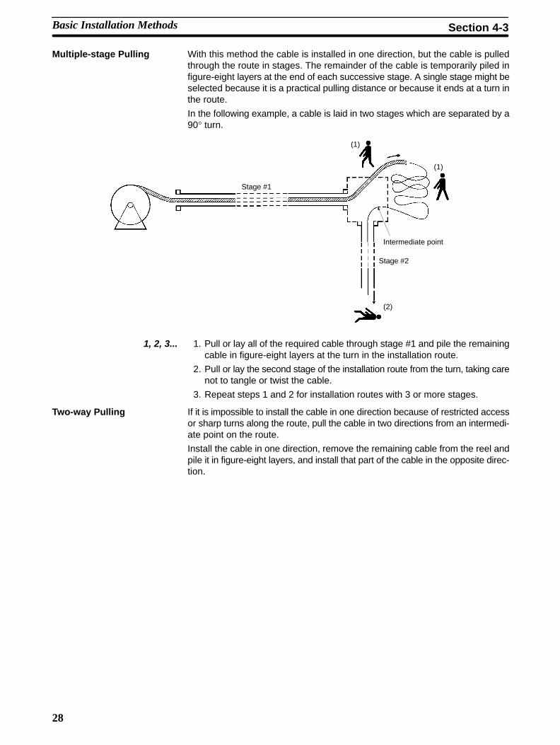
Multiple-stage Pulling With this method the cable is installed in one direction, but the cable is pulledthrough the route in stages. The remainder of the cable is temporarily piled infigure-eight layers at the end of each successive stage. A single stage might beselected because it is a practical pulling distance or because it ends at a turn inthe route.
In the following example, a cable is laid in two stages which are separated by a90° turn.
Stage #1
Stage #2
Intermediate point
(1)
(1)
(2)
1, 2, 3... 1. Pull or lay all of the required cable through stage #1 and pile the remainingcable in figure-eight layers at the turn in the installation route.
2. Pull or lay the second stage of the installation route from the turn, taking carenot to tangle or twist the cable.
3. Repeat steps 1 and 2 for installation routes with 3 or more stages.
Two-way Pulling If it is impossible to install the cable in one direction because of restricted accessor sharp turns along the route, pull the cable in two directions from an intermedi-ate point on the route.
Install the cable in one direction, remove the remaining cable from the reel andpile it in figure-eight layers, and install that part of the cable in the opposite direc-tion.
Basic Installation Methods Section 4-3
29
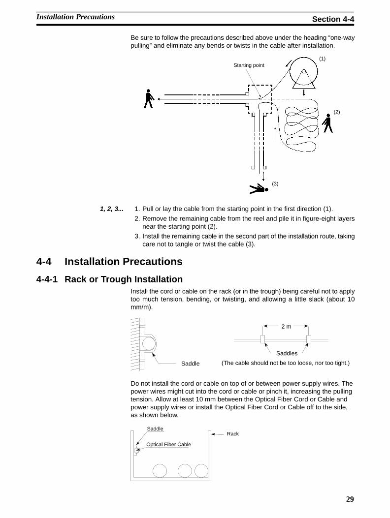
Be sure to follow the precautions described above under the heading “one-waypulling” and eliminate any bends or twists in the cable after installation.
Starting point(1)
(2)
(3)
1, 2, 3... 1. Pull or lay the cable from the starting point in the first direction (1).
2. Remove the remaining cable from the reel and pile it in figure-eight layersnear the starting point (2).
3. Install the remaining cable in the second part of the installation route, takingcare not to tangle or twist the cable (3).
4-4 Installation Precautions
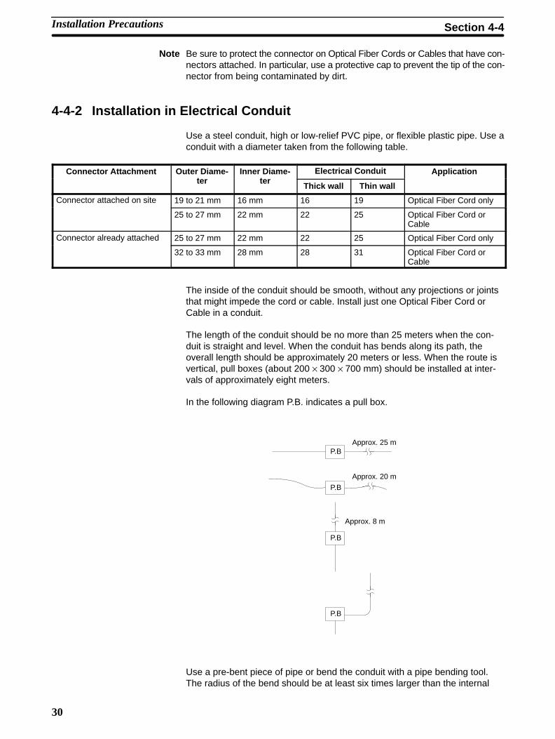
4-4-1 Rack or Trough InstallationInstall the cord or cable on the rack (or in the trough) being careful not to applytoo much tension, bending, or twisting, and allowing a little slack (about 10mm/m).
2 m
Saddle (The cable should not be too loose, nor too tight.)
Saddles
Do not install the cord or cable on top of or between power supply wires. Thepower wires might cut into the cord or cable or pinch it, increasing the pullingtension. Allow at least 10 mm between the Optical Fiber Cord or Cable andpower supply wires or install the Optical Fiber Cord or Cable off to the side,as shown below.
SaddleRack
Optical Fiber Cable
Installation Precautions Section 4-4
30
Note Be sure to protect the connector on Optical Fiber Cords or Cables that have con-nectors attached. In particular, use a protective cap to prevent the tip of the con-nector from being contaminated by dirt.
4-4-2 Installation in Electrical Conduit
Use a steel conduit, high or low-relief PVC pipe, or flexible plastic pipe. Use aconduit with a diameter taken from the following table.
Connector Attachment Outer Diame-t
Inner Diame-t
Electrical Conduit Applicationter ter
Thick wall Thin wall
pp
Connector attached on site 19 to 21 mm 16 mm 16 19 Optical Fiber Cord only
25 to 27 mm 22 mm 22 25 Optical Fiber Cord orCable
Connector already attached 25 to 27 mm 22 mm 22 25 Optical Fiber Cord onlyy
32 to 33 mm 28 mm 28 31 Optical Fiber Cord orCable
The inside of the conduit should be smooth, without any projections or jointsthat might impede the cord or cable. Install just one Optical Fiber Cord orCable in a conduit.
The length of the conduit should be no more than 25 meters when the con-duit is straight and level. When the conduit has bends along its path, theoverall length should be approximately 20 meters or less. When the route isvertical, pull boxes (about 200 × 300 × 700 mm) should be installed at inter-vals of approximately eight meters.
In the following diagram P.B. indicates a pull box.
Approx. 25 m
Approx. 20 m
Approx. 8 m
P.B
P.B
P.B
P.B
Use a pre-bent piece of pipe or bend the conduit with a pipe bending tool.The radius of the bend should be at least six times larger than the internal
Installation Precautions Section 4-4
31
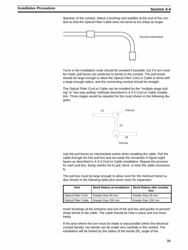
diameter of the conduit. Attach a bushing and saddles at the end of the con-duit so that the Optical Fiber Cable does not bend at too sharp an angle.
Normal conduit bend
Turns in the installation route should be avoided if possible, but if a turn mustbe made, pull boxes are preferred to bends in the conduit. The pull boxesshould be large enough to allow the Optical Fiber Cord or Cable to bend witha large enough radius, and the connecting conduit should be straight.
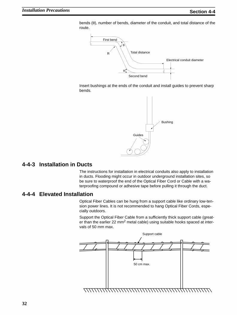
The Optical Fiber Cord or Cable can be installed by the “multiple-stage pull-ing” or “two-way pulling” methods described in 4-3-3 Cord or Cable Installa-tion. Three stages would be required for the route shown in the following dia-gram.
Pull box
Pull box
(1)
(2)
(3)
Use the pull boxes as intermediate points when installing the cable. Pull thecable through the first pull box and set aside the remainder in figure-eightlayers as described in 4-3-3 Cord or Cable Installation. Repeat this processfor each pull box, being careful not to pull, bend, or twist the cable excessive-ly.
The pull box must be large enough to allow room for the minimum bend ra-dius shown in the following table plus some room for expansion.
Item Bend Radius at Installation Bend Radius after Installa-tion
Optical Fiber Cord Greater than 60 mm Greater than 30 mm
Optical Fiber Cable Greater than 200 mm Greater than 100 mm
Insert bushings at the entrance and exit of the pull box and guides to preventsharp bends in the cable. The cable should be held in place and not movefreely.
If the area where the turn must be made is inaccessible (when the electricalconduit bends), two bends can be made very carefully in the conduit. Theinstallation will be limited by the radius of the bends (R), angle of the
Installation Precautions Section 4-4
32
bends (θ), number of bends, diameter of the conduit, and total distance of theroute.
First bend
Total distance
Second bend
Electrical conduit diameter
R
θ
θ
Insert bushings at the ends of the conduit and install guides to prevent sharpbends.
Bushing
Guides
4-4-3 Installation in DuctsThe instructions for installation in electrical conduits also apply to installationin ducts. Flooding might occur in outdoor underground installation sites, sobe sure to waterproof the end of the Optical Fiber Cord or Cable with a wa-terproofing compound or adhesive tape before pulling it through the duct.
4-4-4 Elevated InstallationOptical Fiber Cables can be hung from a support cable like ordinary low-ten-sion power lines. It is not recommended to hang Optical Fiber Cords, espe-cially outdoors.
Support the Optical Fiber Cable from a sufficiently thick support cable (great-er than the earlier 22 mm2 metal cable) using suitable hooks spaced at inter-vals of 50 mm max.
50 cm max.
Support cable
Installation Precautions Section 4-4
33
Gently unreel the Optical Fiber Cable at less than 10 m/min by spinning thereel, so that no pulling tension is applied to the Optical Fiber Cable itself. Besure not to apply any force to the cable (tension, bending, compression,twisting, or impact) during installation that exceeds its maximum specifica-tions.
The minimum bend radius for an Optical Fiber Cable during installation is200 mm (20 times the cable diameter). Use a a tool such as a pulley atbends of the cable to ensure that the bends exceed the minimum radius.
When installing straight sections, use pulleys as guides to ensure that thetension on the cable does not exceed the maximum value. Set the pulleys nomore than 25 meters apart and allow the cable to sag at least 0.5 m.
Use a tension meter to monitor the tension in the cable if it is suspected to betoo high, and pull the cable along the installation route by hand or othermeans if the tension is found to be too high.
Note It is good practice to leave about 2 or 3 meters of spare cable before eachnode connection. This margin of cable allows room for attaching the connec-tor and some repositioning of the node.
4-5 Securing the Cord or CableAfter laying the Optical Fiber Cord or Cable along the installation route, removethe tape or tube used to protect the end of the cable. If a ferrule is going to beattached to the end of the cable, clean the end of the ferrule surface with waterand wipe it with a soft, clean, and lint-free cloth or paper towel.
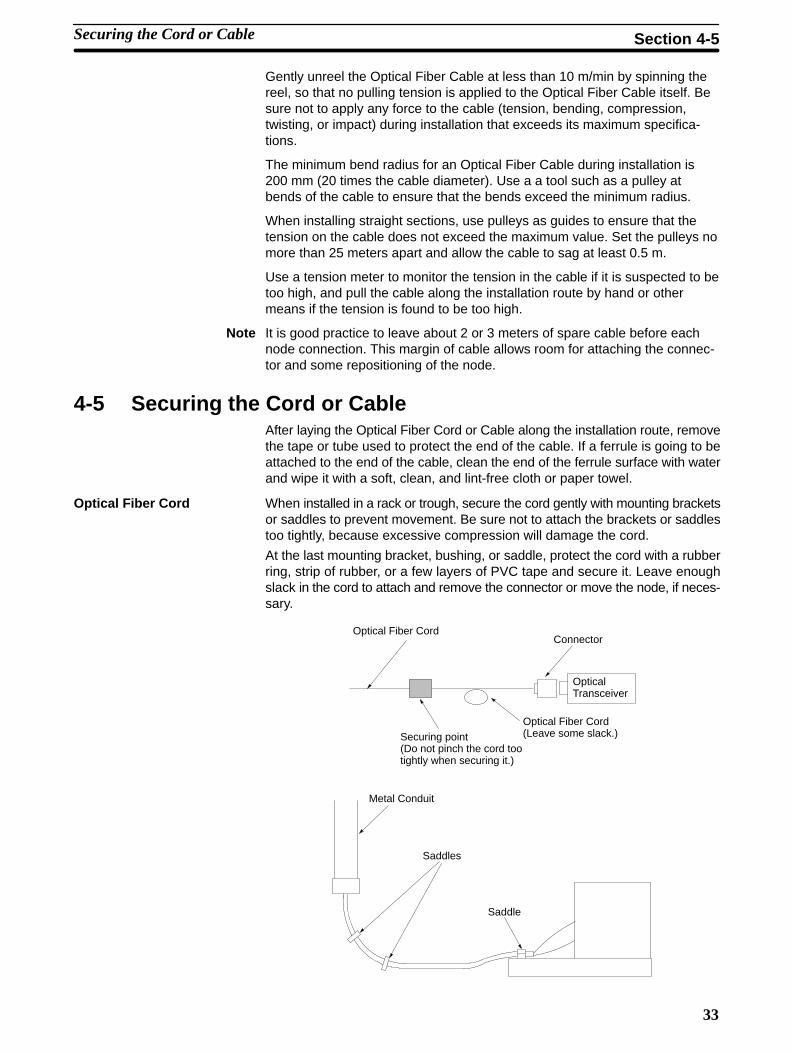
Optical Fiber Cord When installed in a rack or trough, secure the cord gently with mounting bracketsor saddles to prevent movement. Be sure not to attach the brackets or saddlestoo tightly, because excessive compression will damage the cord.
At the last mounting bracket, bushing, or saddle, protect the cord with a rubberring, strip of rubber, or a few layers of PVC tape and secure it. Leave enoughslack in the cord to attach and remove the connector or move the node, if neces-sary.
Optical Fiber Cord
Securing point(Do not pinch the cord tootightly when securing it.)
Optical Fiber Cord(Leave some slack.)
Connector
OpticalTransceiver
Metal Conduit
Saddles
Saddle
Securing the Cord or Cable Section 4-5
34
Optical Fiber Cable When installed in a rack or trough, secure the cable with mounting brackets orsaddles to prevent movement. Be sure not to attach the brackets or saddles tootightly, because excessive compression will damage the cable.
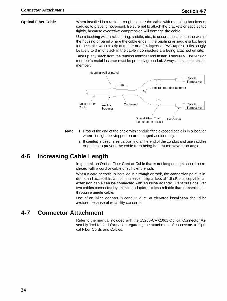
Use a bushing with a rubber ring, saddle, etc., to secure the cable to the wall ofthe housing or panel where the cable ends. If the bushing or saddle is too largefor the cable, wrap a strip of rubber or a few layers of PVC tape so it fits snugly.Leave 2 to 3 m of slack in the cable if connectors are being attached on site.
Take up any slack from the tension member and fasten it securely. The tensionmember’s metal fastener must be properly grounded. Always secure the tensionmember.
Optical FiberCable
Optical Fiber Cord(Leave some slack.)
OpticalTransceiver
Tension member fastener
Housing wall or panel
Cable end
50
OpticalTransceiver
Connector
Anchorbushing
Note 1. Protect the end of the cable with conduit if the exposed cable is in a locationwhere it might be stepped on or damaged accidentally.
2. If conduit is used, insert a bushing at the end of the conduit and use saddlesor guides to prevent the cable from being bent at too severe an angle.
4-6 Increasing Cable LengthIn general, an Optical Fiber Cord or Cable that is not long enough should be re-placed with a cord or cable of sufficient length.
When a cord or cable is installed in a trough or rack, the connection point is in-doors and accessible, and an increase in signal loss of 1.5 dB is acceptable, anextension cable can be connected with an inline adapter. Transmissions withtwo cables connected by an inline adapter are less reliable than transmissionsthrough a single cable.
Use of an inline adapter in conduit, duct, or elevated installation should beavoided because of reliability concerns.
4-7 Connector AttachmentRefer to the manual included with the S3200-CAK1062 Optical Connector As-sembly Tool Kit for information regarding the attachment of connectors to Opti-cal Fiber Cords and Cables.
Connector Attachment Section 4-7
35
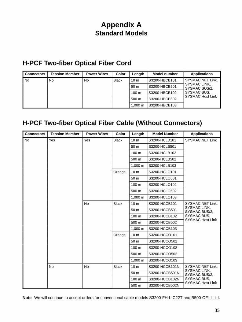
Appendix AStandard Models
H-PCF Two-fiber Optical Fiber Cord
Connectors Tension Member Power Wires Color Length Model number Applications
No No No Black 10 m S3200-HBCB101 SYSMAC NET Link,SYSMAC LINK
50 m S3200-HBCB501SYSMAC LINK,SYSMAC BUS/2,
100 m S3200-HBCB102SYSMAC BUS/2,SYSMAC BUS,SYSMAC Host Link
500 m S3200-HBCB502SYSMAC Host Link
1,000 m S3200-HBCB103
H-PCF Two-fiber Optical Fiber Cable (Without Connectors)
Connectors Tension Member Power Wires Color Length Model Number Applications
No Yes Yes Black 10 m S3200-HCLB101 SYSMAC NET Link
50 m S3200-HCLB501
100 m S3200-HCLB102
500 m S3200-HCLB502
1,000 m S3200-HCLB103
Orange 10 m S3200-HCLO101
50 m S3200-HCLO501
100 m S3200-HCLO102
500 m S3200-HCLO502
1,000 m S3200-HCLO103
No Black 10 m S3200-HCCB101 SYSMAC NET Link,SYSMAC LINK
50 m S3200-HCCB501SYSMAC LINK,SYSMAC BUS/2,
100 m S3200-HCCB102SYSMAC BUS/2,SYSMAC BUS,SYSMAC Host Link
500 m S3200-HCCB502SYSMAC Host Link
1,000 m S3200-HCCB103
Orange 10 m S3200-HCCO101
50 m S3200-HCCO501
100 m S3200-HCCO102
500 m S3200-HCCO502
1,000 m S3200-HCCO103
No No Black 10 m S3200-HCCB101N SYSMAC NET Link,SYSMAC LINK
50 m S3200-HCCB501NSYSMAC LINK,SYSMAC BUS/2,
100 m S3200-HCCB102NSYSMAC BUS/2,SYSMAC BUS,SYSMAC Host Link
500 m S3200-HCCB502NSYSMAC Host Link
Note We will continue to accept orders for conventional cable models S3200-FH-L-C22T and B500-OF���.
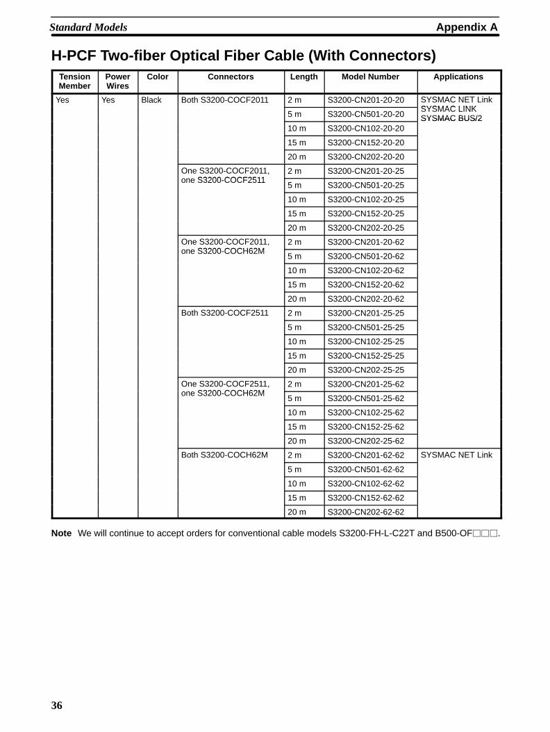
Appendix AStandard Models
36
H-PCF Two-fiber Optical Fiber Cable (With Connectors)TensionMember
PowerWires
Color Connectors Length Model Number Applications
Yes Yes Black Both S3200-COCF2011 2 m S3200-CN201-20-20 SYSMAC NET LinkSYSMAC LINK
5 m S3200-CN501-20-20SYSMAC LINKSYSMAC BUS/2
10 m S3200-CN102-20-20SYSMAC BUS/2
15 m S3200-CN152-20-20
20 m S3200-CN202-20-20
One S3200-COCF2011,S3200 COCF2511
2 m S3200-CN201-20-25one S3200-COCF2511
5 m S3200-CN501-20-25
10 m S3200-CN102-20-25
15 m S3200-CN152-20-25
20 m S3200-CN202-20-25
One S3200-COCF2011,S3200 COCH62M
2 m S3200-CN201-20-62one S3200-COCH62M
5 m S3200-CN501-20-62
10 m S3200-CN102-20-62
15 m S3200-CN152-20-62
20 m S3200-CN202-20-62
Both S3200-COCF2511 2 m S3200-CN201-25-25
5 m S3200-CN501-25-25
10 m S3200-CN102-25-25
15 m S3200-CN152-25-25
20 m S3200-CN202-25-25
One S3200-COCF2511,S3200 COCH62M
2 m S3200-CN201-25-62one S3200-COCH62M
5 m S3200-CN501-25-62
10 m S3200-CN102-25-62
15 m S3200-CN152-25-62
20 m S3200-CN202-25-62
Both S3200-COCH62M 2 m S3200-CN201-62-62 SYSMAC NET Link
5 m S3200-CN501-62-62
10 m S3200-CN102-62-62
15 m S3200-CN152-62-62
20 m S3200-CN202-62-62
Note We will continue to accept orders for conventional cable models S3200-FH-L-C22T and B500-OF���.
Appendix AStandard Models
37
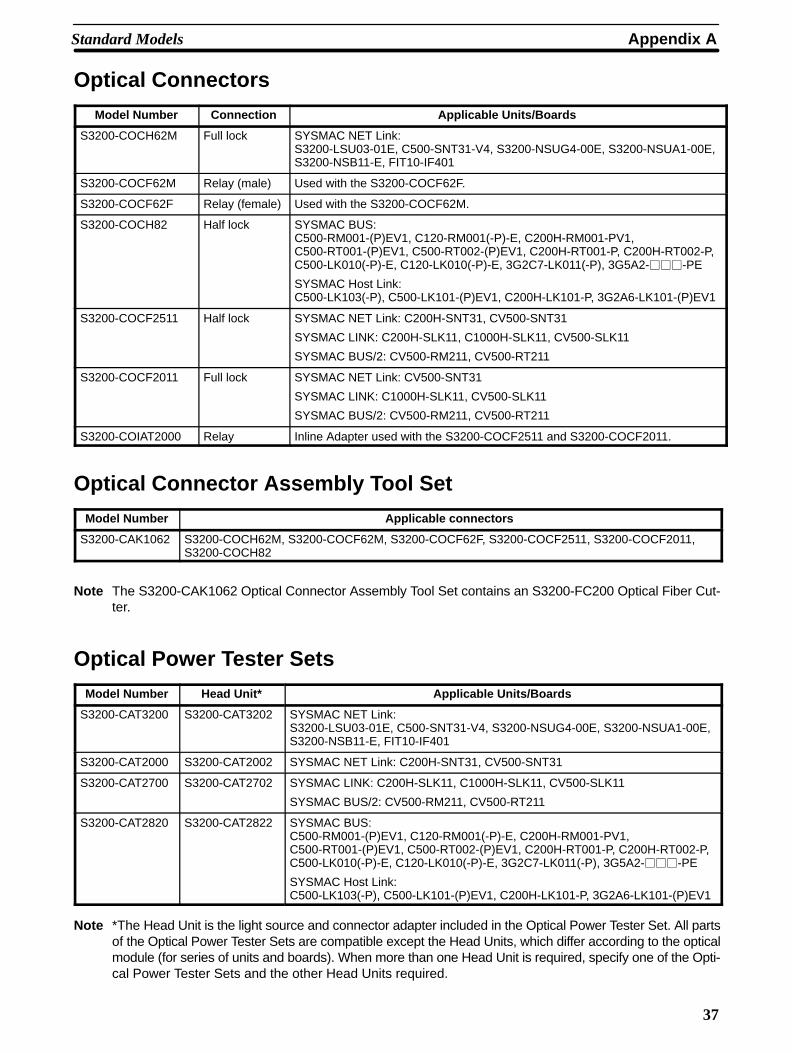
Optical Connectors
Model Number Connection Applicable Units/Boards
S3200-COCH62M Full lock SYSMAC NET Link:S3200-LSU03-01E, C500-SNT31-V4, S3200-NSUG4-00E, S3200-NSUA1-00E,S3200-NSB11-E, FIT10-IF401
S3200-COCF62M Relay (male) Used with the S3200-COCF62F.
S3200-COCF62F Relay (female) Used with the S3200-COCF62M.
S3200-COCH82 Half lock SYSMAC BUS:C500-RM001-(P)EV1, C120-RM001(-P)-E, C200H-RM001-PV1,C500-RT001-(P)EV1, C500-RT002-(P)EV1, C200H-RT001-P, C200H-RT002-P,C500-LK010(-P)-E, C120-LK010(-P)-E, 3G2C7-LK011(-P), 3G5A2-���-PE
SYSMAC Host Link:C500-LK103(-P), C500-LK101-(P)EV1, C200H-LK101-P, 3G2A6-LK101-(P)EV1
S3200-COCF2511 Half lock SYSMAC NET Link: C200H-SNT31, CV500-SNT31
SYSMAC LINK: C200H-SLK11, C1000H-SLK11, CV500-SLK11
SYSMAC BUS/2: CV500-RM211, CV500-RT211
S3200-COCF2011 Full lock SYSMAC NET Link: CV500-SNT31
SYSMAC LINK: C1000H-SLK11, CV500-SLK11
SYSMAC BUS/2: CV500-RM211, CV500-RT211
S3200-COIAT2000 Relay Inline Adapter used with the S3200-COCF2511 and S3200-COCF2011.
Optical Connector Assembly Tool Set
Model Number Applicable connectors
S3200-CAK1062 S3200-COCH62M, S3200-COCF62M, S3200-COCF62F, S3200-COCF2511, S3200-COCF2011,S3200-COCH82
Note The S3200-CAK1062 Optical Connector Assembly Tool Set contains an S3200-FC200 Optical Fiber Cut-ter.
Optical Power Tester Sets
Model Number Head Unit* Applicable Units/Boards
S3200-CAT3200 S3200-CAT3202 SYSMAC NET Link:S3200-LSU03-01E, C500-SNT31-V4, S3200-NSUG4-00E, S3200-NSUA1-00E,S3200-NSB11-E, FIT10-IF401
S3200-CAT2000 S3200-CAT2002 SYSMAC NET Link: C200H-SNT31, CV500-SNT31
S3200-CAT2700 S3200-CAT2702 SYSMAC LINK: C200H-SLK11, C1000H-SLK11, CV500-SLK11
SYSMAC BUS/2: CV500-RM211, CV500-RT211
S3200-CAT2820 S3200-CAT2822 SYSMAC BUS:C500-RM001-(P)EV1, C120-RM001(-P)-E, C200H-RM001-PV1,C500-RT001-(P)EV1, C500-RT002-(P)EV1, C200H-RT001-P, C200H-RT002-P,C500-LK010(-P)-E, C120-LK010(-P)-E, 3G2C7-LK011(-P), 3G5A2-���-PE
SYSMAC Host Link:C500-LK103(-P), C500-LK101-(P)EV1, C200H-LK101-P, 3G2A6-LK101-(P)EV1
Note *The Head Unit is the light source and connector adapter included in the Optical Power Tester Set. All partsof the Optical Power Tester Sets are compatible except the Head Units, which differ according to the opticalmodule (for series of units and boards). When more than one Head Unit is required, specify one of the Opti-cal Power Tester Sets and the other Head Units required.
Appendix AStandard Models
38
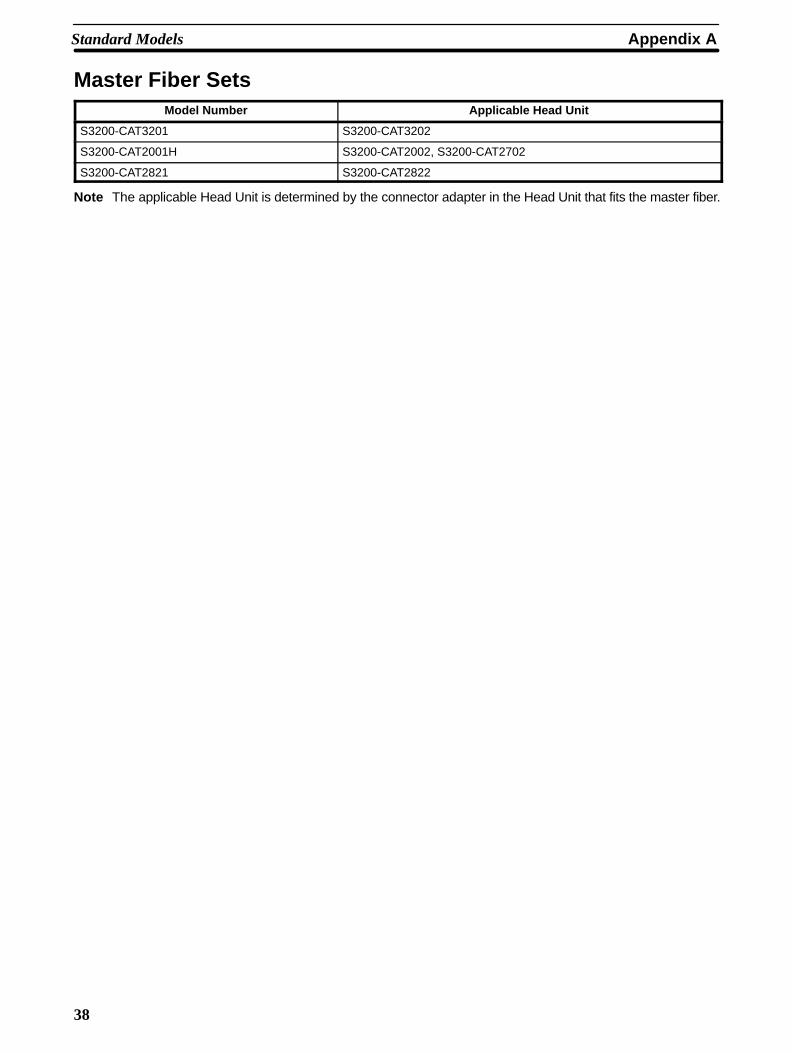
Master Fiber SetsModel Number Applicable Head Unit
S3200-CAT3201 S3200-CAT3202
S3200-CAT2001H S3200-CAT2002, S3200-CAT2702
S3200-CAT2821 S3200-CAT2822
Note The applicable Head Unit is determined by the connector adapter in the Head Unit that fits the master fiber.
39
Glossary
dBm A unit for expressing power level in decibels, relative to a reference level ofone milliwatt.
ferrule A short tube which is attached to the end of an optical fiber and is part of theoptical fiber connector.
H–PCF Hard-clad plastic cable fiber.
LAN An acronym for local area network.
local area network A network consisting of nodes or positions in a loop arrangement. Each nodecan be any one of a number of devices. This kind of network usually oper-ates over a small area such as a group of offices or a factory floor.
Programmable Controller A small, computer-like device that can control peripheral equipment, such asan electric door or quality control devices, based on programming and pe-ripheral input devices. Any process that can be controlled using electricalsignals can be controlled by a PC. PCs can be used independently or net-worked together into a system to control more complex operations.
pull box A box which allows access to optical fiber cable in a conduit. Pull boxes areused to pull the cable through sections of conduit during installation.
PVC Polyvinyl chloride. The outer layer or sheath on the optical fiber cable.
tension member A steel wire running through an optical fiber cable. It is used to give the cablelongitudinal strength.

41
Index
�
baseband frequency, 4
�
cable length, increasing, 34
conduit, installing cord or cable in conduit, 27, 30
connectorsassembly, 17attaching, 34construction, 16contents of Optical Connector Assembly Tool Kit, 18corresponding units/boards, 15Optical Connector dimensions, 14
cord length, increasing, 34
�
ducts, installing cord or cable in ducts, 32
�
elevated installation, suspending cord or cable from supportcable, 32
�
Inline Adapter, testing optical power transmission, 21
inspection, points inspected prior to shipping, 12
installationcable preparation, 26cord preparation, 24elevated, 32in conduit, 27, 30in ducts, 32in racks, 29in troughs, 29introduction, 24recommended installation methods, 24securing the cord or cable, 33
�
Master Fiber Sets, 19
�
numerical aperture, 4
�
Optical Connector Assembly Tool Kit, 18
Optical Fiber Cablecomponent materials, 9preparation for installation, 26specifications, 10
Optical Fiber Cordcomponent materials, 8preparation for installation, 24specifications, 10
Optical Power Testers, 19
ordering information, 35
rack, installing cord or cable in racks, 29
signal lossvs. temperature, 5vs. transmission distance, 3vs. wavelength, 3
specifications, 10
standard models, 35
�
testingoptical power testing, 19using Optical Power Testers, 20
transmission loss. See signal loss
trough, installing cord or cable in troughs, 29
43
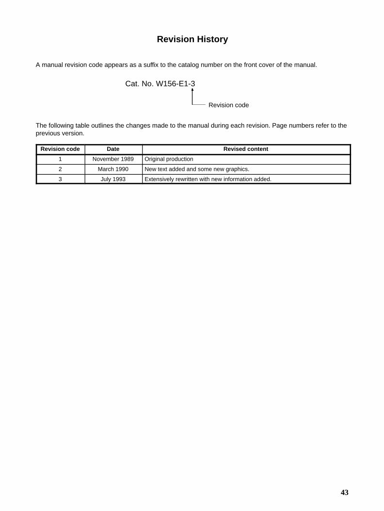
Revision History
A manual revision code appears as a suffix to the catalog number on the front cover of the manual.
Cat. No. W156-E1-3
Revision code
The following table outlines the changes made to the manual during each revision. Page numbers refer to theprevious version.
Revision code Date Revised content
1 November 1989 Original production
2 March 1990 New text added and some new graphics.
3 July 1993 Extensively rewritten with new information added.

OMRON CorporationFA Systems Division H.Q.66 Matsumoto Mishima-city, Shizuoka 411-8511 JapanTel: (81)55-977-9181/Fax: (81)55-977-9045
Regional Headquarters
OMRON EUROPE B.V.Wegalaan 67-69, NL-2132 JD HoofddorpThe NetherlandsTel: (31)2356-81-300/Fax: (31)2356-81-388
OMRON ELECTRONICS LLC1 East Commerce Drive, Schaumburg, IL 60173U.S.A.Tel: (1)847-843-7900/Fax: (1)847-843-8568
OMRON ASIA PACIFIC PTE. LTD.83 Clemenceau Avenue, #11-01, UE Square,Singapore 239920Tel: (65)6835-3011/Fax: (65)6835-2711
Cat. No. W156-E1-3 Note: Specifications subject to change without notice. Printed in Japan0793-2M
Authorized Distributor:


