H27E-11 Gas Stove | 1 H27E Direct Vent Gas Stove Model H27E-NG11 H27E-LP11 Fuel Type Natural Gas Propane Minimum Supply Pressure 5” W.C. (1.25 kPa) 11” W.C. (2.74 kPa) Manifold Pressure - High 3.5” W.C. (0.87 kPa) 10” W.C. (2.49 kPa) Manifold Pressure - Low 1.6” W.C. (0.40 kPa) 6.4” W.C. (1.59 kPa) Orifice Size #42 DMS #54 DMS Minimum Input 18,000 BTU/h (5.28 kW) 17,500 BTU/h (5.13 kW) Maximum Input 25,000 BTU/h (7.32 kW) 22,000 BTU/h (6.45 kW) Vent Sizing (Rear Vent) 4” Inner / 6-5/8” Outer 4” Inner / 6-5/8” Outer Vent Sizing (Top Vent) 4” Inner / 6-5/8” Outer 4” Inner / 6-5/8” Outer CSA P.4.1 61.22% 63.07% Approved Venting Systems Flex Vent Systems: FPI AstroCap™ Flex Vent Rigid Pipe Vent Systems: Simpson Direct Vent Pro® Selkirk Direct-Temp™ Metal-Fab® Sure Seal American Metal Products® Amerivent Direct Security Secure-Vent™ ICC Excel Direct 17 13/16” (452 mm) 17 13/16” (452 mm) CLEARANCES TO COMBUSTIBLES The clearances listed are MINIMUM distances. Measure the clearance to both the appliance and the chimney connector. The farthest distance is correct if the two clearances do not coincide. For example, if the appliance is set as indicated in one of the figures but the connector is too close, move the stove until the correct clearance to the connector is obtained. This appliance may be installed only with the clearances as shown in the situations pictured. Do not combine clearances from one type of installation with another in order to achieve closer clearances. This unit can be installed on a solid combustible surface like a wood floor. This unit can also be installed directly on carpeting or vinyl. Use the minimum clearances shown in the diagrams below: H27E-NG11 & H27E-LP11 Clearances A Left Side Wall to Unit* 6" / 150 mm B Back Wall to Unit 3" / 75 mm C Vertical Vent Pipe to Back Wall 2" / 50 mm E Unit Corner to Wall 2" /50 mm Unit Top to Alcove Ceiling 24" / 610 mm Minimum ceiling height is 24" /610 mm from top of unit.
Transcript
H27E-11GasStove |1
H27E Direct Vent Gas StoveModel H27E-NG11 H27E-LP11
Rigid Pipe Vent Systems: Simpson Direct Vent Pro®Selkirk Direct-Temp™Metal-Fab® Sure SealAmerican Metal Products® Amerivent DirectSecurity Secure-Vent™ICC Excel Direct
17 13/16”(452 mm)
17 13/16”(452 mm)
CLEARANCES TO COMBUSTIBLES
TheclearanceslistedareMINIMUMdistances.Measuretheclearancetoboththeapplianceandthechimneyconnector.The farthest distance is correct if the two clearances do not coincide.
Thisappliancemaybeinstalledonlywiththeclearancesasshowninthesituationspictured.Do not combine clearances from one type of installation with another in order to achieve closer clearances.
Vertical Terminations Systems for Residential Manufactured and Mobile Homes
The shaded area in the diagram below shows all allowable combinations of straight vertical and offset to vertical runs with vertical terminations.Maximum two 45o elbows.
May be installed in Manufactured (Mobile) Homes after first sale.
Horizontal Terminations for All Venting Systems
The shaded areas in the diagram below show allallowablecombinationsofverticalrunswithhorizontalterminations.Maximumone90Oelbow(two45oelbowsequalone90oelbow).
Propane and Natural Gas: Residential, Manufactured and Mobile Homes Installations
May be installed in Manufactured (Mobile) Homes after first sale.
The two diagrams show all allowable combinations of straight horizontal termination with one 45o elbow off the unit with Snorkels or FPI Riser Vent. Restrictor position "A".
4| H27E-11GasStove
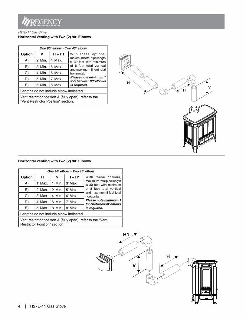
H27E-11 Gas StoveHorizontal Venting with Two (2) 90o Elbows
Horizontal Venting with Two (2) 90o Elbows
H
H1
V
One 90o elbow = Two 45o elbow
Option V H + H1 With these opt ions,maximumtotalpipelengthis 30 feet with minimumof 6 feet total verticalandmaximum8feettotalhorizontal.Please note minimum 1 foot between 90o elbows is required.
Option H V H + H1 With these opt ions,maximumtotalpipelengthis 30 feet with minimumof 8 feet total verticalandmaximum8feettotalhorizontal.Please note minimum 1 foot between 90o elbows is required.
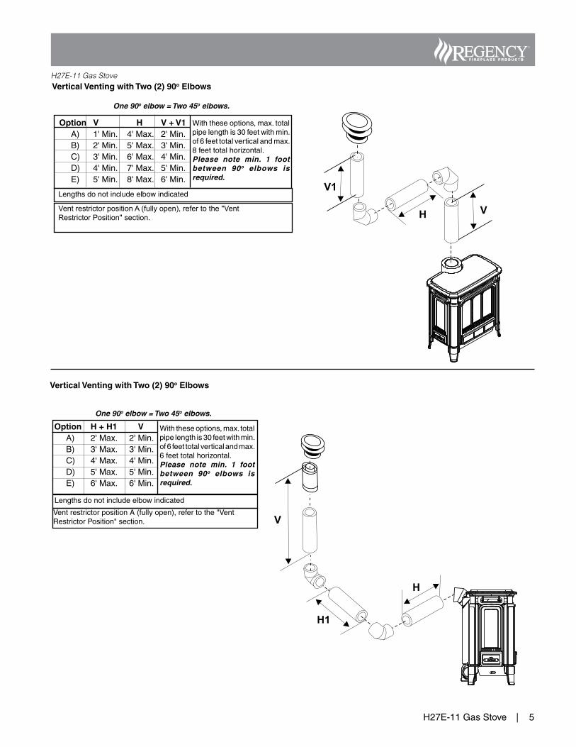
H27E-11 Gas StoveVertical Venting with Two (2) 90o Elbows
Vertical Venting with Two (2) 90o Elbows
One 90o elbow = Two 45o elbows.
V1
VH
Option V H V + V1 A) 1'Min. 4'Max. 2'Min. B) 2'Min. 5'Max. 3'Min. C) 3'Min. 6'Max. 4'Min. D) 4'Min. 7'Max. 5'Min. E) 5'Min. 8'Max. 6'Min.
Withtheseoptions,max.totalpipelengthis30feetwithmin.of6feettotalverticalandmax.8feettotalhorizontal.Please note min. 1 foot between 90o elbows is required.
Vent restrictor position A (fully open), refer to the "Vent Restrictor Position" section.
Lengthsdonotincludeelbowindicated
Option H + H1 V A) 2'Max. 2'Min. B) 3'Max. 3'Min. C) 4'Max. 4'Min. D) 5'Max. 5'Min. E) 6'Max. 6'Min.
Withtheseoptions,max.totalpipelengthis30feetwithmin.of6feettotalverticalandmax.6feettotalhorizontal.Please note min. 1 foot between 90o elbows is required.
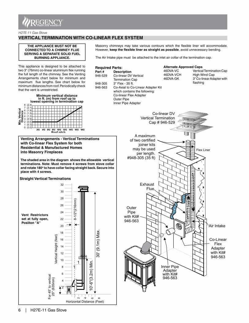
Venting Arrangements - Vertical Terminations with Co-linear Flex System for bothResidential & Manufactured Homes into Masonry Fireplaces
The shaded area in the diagram shows the allowable vertical terminations. Note: Must remove 4 screws from stove collar and rotate 180o to have collar facing straight back. Secure into place with 4 screws.
VERTICAL TERMINATION WITH CO-LINEAR FLEX SYSTEM
This appliance is designed to be attached totwo3"(76mm)co-linearaluminiumflexrunningthefulllengthofthechimney.SeetheVentingArrangements chart below for minimum andmaximum flue lengths. See chart below forminimumdistancesfromroof.Periodicallycheckthattheventisunrestricted.
Masonry chimneys may take various contours which the flexible liner will accommodate.However,keep the flexible liner as straight as possible,avoidunnecessarybending.
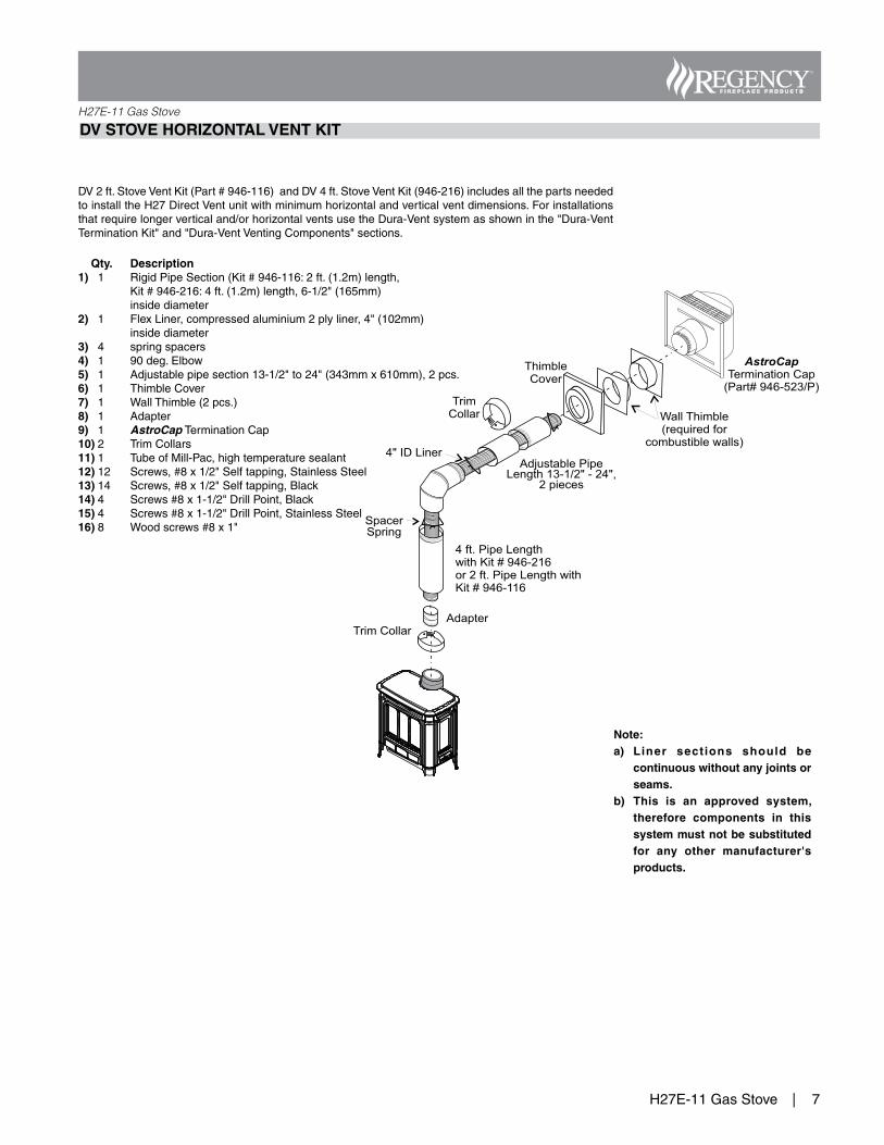
b) This is an approved system, therefore components in this system must not be substituted for any other manufacturer's products.
8| H27E-11GasStove
H27E-11 Gas Stove
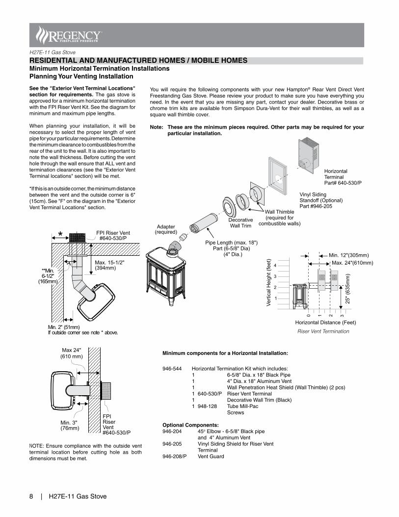
Pipe Length (max. 18")Part (6-5/8" Dia)
(4" Dia.)
DecorativeWall Trim
HorizontalTerminalPart# 640-530/P
Wall Thimble(required for
combustible walls)
Vinyl SidingStandoff (Optional)Part #946-205
Adapter(required)
RESIDENTIAL AND MANUFACTURED HOMES / MOBILE HOMES Minimum Horizontal Termination InstallationsPlanning Your Venting Installation
You will require the following components with your new Hampton® RearVent DirectVentFreestandingGasStove.Pleasereviewyourproducttomakesureyouhaveeverythingyouneed. In theevent that youaremissinganypart, contact yourdealer.Decorativebrassorchrometrimkitsareavailable fromSimpsonDura-Vent for theirwall thimbles,aswellasasquarewallthimblecover.
Note: These are the minimum pieces required. Other parts may be required for your particular installation.
See the "Exterior Vent Terminal Locations" section for requirements. Thegasstove isapprovedforaminimumhorizontalterminationwiththeFPIRiserVentKit.Seethediagramforminimumandmaximumpipelengths.
When planning your installation, it will benecessarytoselecttheproper lengthofventpipeforyourparticularrequirements.Determinetheminimumclearancetocombustiblesfromtherearoftheunittothewall.Itisalsoimportanttonotethewallthickness.BeforecuttingtheventholethroughthewallensurethatALLventandterminationclearances(seethe"ExteriorVentTerminallocations"section)willbemet.
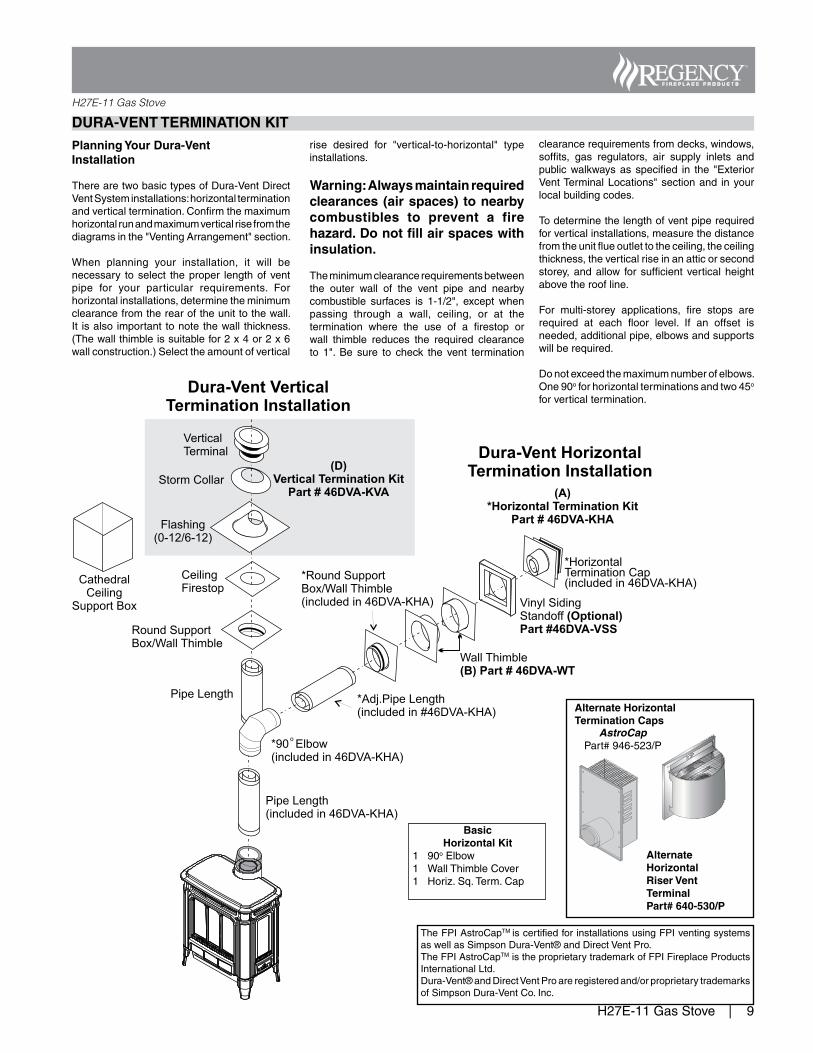
When planning your installation, it will benecessary toselect theproper lengthofventpipe for your particular requirements. Forhorizontalinstallations,determinetheminimumclearancefromtherearoftheunittothewall.It isalso important tonotethewall thickness.(Thewallthimbleissuitablefor2x4or2x6wallconstruction.)Selecttheamountofvertical
rise desired for "vertical-to-horizontal" typeinstallations.
Warning: Always maintain required clearances (air spaces) to nearby combustibles to prevent a fire hazard. Do not fill air spaces with insulation.
Theminimumclearancerequirementsbetweenthe outer wall of the vent pipe and nearbycombustible surfaces is 1-1/2", except whenpassing through a wall, ceiling, or at thetermination where the use of a firestop orwall thimble reduces the required clearanceto 1". Be sure to check the vent termination
clearancerequirementsfromdecks,windows,soffits, gas regulators, air supply inlets andpublicwalkwaysasspecified in the "ExteriorVentTerminalLocations"sectionand inyourlocalbuildingcodes.
Todeterminethelengthofventpiperequiredforverticalinstallations,measurethedistancefromtheunitflueoutlettotheceiling,theceilingthickness,theverticalriseinanatticorsecondstorey,andallow for sufficient verticalheightabovetheroofline.
For multi-storey applications, fire stops arerequired at each floor level. If an offset isneeded,additionalpipe,elbowsandsupportswillberequired.