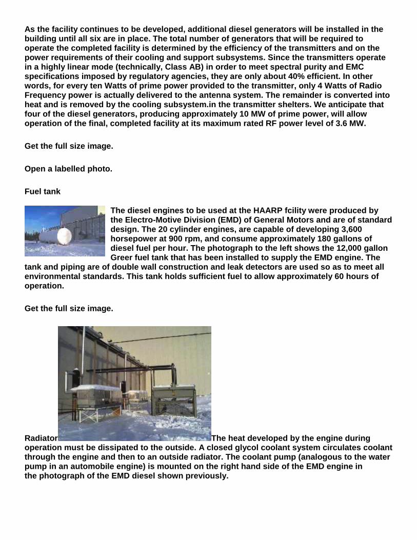
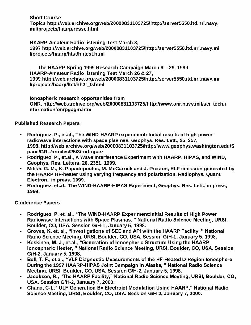
HAARP – Tales from the Crypt Posted on February 19, 2013 by rezn8d THIS ARTICLE IS PART OF THE SERIES: HAARP AND THE SKY HEATERS ALSO SEE OUR SPACE-WEATHER MODIFICATION TIMELINE DELETED HAARP WEBPAGES brought back from the dead by archive.org WHAT IS HAARP? HOW IT LOOKS AND SOUNDS! Posted: BJNEWS 12/15/00 http://www.brojon.org/frontpage/bj1203.html ( NOTE: Both the above graphic and the sound player were optimized for most versions of IE and Netscape. If you can’t see the graph or hear the sound then cut-and-paste the graph to
Transcript
HAARP – Tales from the Crypt
Posted on February 19, 2013 by rezn8d
THIS ARTICLE IS PART OF THE SERIES: HAARP AND THE SKY HEATERS
ALSO SEE OUR SPACE-WEATHER MODIFICATION TIMELINE
DELETED HAARP WEBPAGES
brought back from the dead by archive.org
WHAT IS HAARP?
HOW IT LOOKS AND SOUNDS!
Posted: BJNEWS 12/15/00
http://www.brojon.org/frontpage/bj1203.html
( NOTE: Both the above graphic and the sound player were optimized for most versions of IE and Netscape. If you can’t see the graph or hear the sound then cut-and-paste the graph to
your computer and download either the 1.0Mb wav file, haarp.wav , or the 44Kb mp3 file,haarp.mp3 . If your computer and browser are so old and clunky they won’t do any of those, then as they said 100 years ago, “Get A Horse!!” )
HAARP (High-Frequency Active Auroral Research Program) is a high-powered radio transmission research facility jointly operated by the US Navy, Air Force and several universities. Because of the high secrecy surrounding the government HAARP project, many theories have risen trying to explain what HAARP is and does. Most of them are simply wild speculations, based on fears about what “they are doing up there.” It is the purpose of this article to provide sufficient technical expertise to dispel the mystery.
The above HAARP signal was monitored on 3.39 MHZ and recorded in San Jose, California, about 5,000 miles from the transmitter in Gakona, eastern central Alaska. At that distance and frequency, the signal can only be heard during the night after two F-layer ionospheric skips. Some short-term signal fading over the signal path may be the cause for the variations in the smooth roll-off in the amplitude from 1 sec to the end of the pulse at 6.25 secs. These loud 6 second pulses are usually repeated with a quiet 15 or 30 second pause between pulses.
1. HAARP and ULF (Ultra Low Frequency) Waves
The HAARP sound recording may seem full of static. It is not. The rushing roaring sound of a blow torch is the HAARP signal itself, as shown by the silence or background noise of the receiver at the end of the pulse, and by the clarity of the tones at the beginning. If you wanted to see or hear the ULF (ultra low frequency) waves sent out by the HAARP transmitter, you will be disappointed here.
My receiver is not equipped to record ULF waves in the region of 1 to 10 Hz, and has an audio roll-off in the range of about 30 Hz. And besides, you can’t hear or see a 0.9 or 1 Hz signal anyway. It is way below the range of normal human hearing. You need instruments to sense it. A powerful 1 Hz sound would probably be “sensed” as a slow rolling earthquake or a slight rocking motion as on the ocean. Nonetheless, a major component and purpose of the HAARP signal is an audio modulation at the frequency of about 0.9 Hz. And what is that purpose? I’ll get to that in a moment.
2. HAARP Interaction with the Atmosphere
The HAARP pulse is primarily divided into two components. The first part is the sections marked A and B on the chart and is the powerful “pre-heat” megawatt pulse aimed upward at the ionosphere just above the HAARP facility. As the radio waves travel up through the atmosphere they have no effect until they reach the ionosphere about 200 kilometers above the earth, which is far above the atmosphere. At that point the waves interact with the ions, which may be electrons, protons or ionized parts of atoms like oxygen, ozone or nitrogen.
Normally the particles in the near vacuum of outer-space in the region of the ionosphere are simply moving randomly in all directions. Some particles may hit each other and re-combine into normal atoms of oxygen and nitrogen, thus simply becoming a part of the atmosphere. Other particles may drift off into space and others may move downward into the thicker atmosphere where they re-combine. Then along comes the HAARP signal.
For about a quarter second during the part A and B of the pulse, the randomly moving ions are now forced to madly race back and forth in the direction of the radio waves at the speed of light or 300,000 kilometers per second, which is real fast. Many of them strike atoms in the upper atmosphere and cause the atoms to also become ionized. Thus the number of ions is suddenly increased. Since the neutral atoms in the atmosphere do not react to the radio waves, they remain more or less stationary, and become “sitting ducks” just waiting to be hit by one of the billions of racing ions all rushing back and forth in response to the HAARP waves.
Even if the neutral atoms don’t become ionized, many of them are struck by the fast ions and soon most of the atmospheric atoms high above the HAARP transmitter are also rushing in all directions but not back and forth as are the ions. This sudden increase in the motion of both the atoms and ions in the upper atmosphere is called “ionospheric heating.” In fact, the HAARP facility, along with several similar research instruments in Europe and Russia, are in the category of Ionospheric Heaters. But its what HAARP does next during the part C of the pulse which makes HAARP unique.
3. Components of the HAARP Pulse
In portion A of the pulse, identifier tones are sent at frequencies of 360, 1000 and 1700 Hz, with some harmonics at higher frequencies visible on the graph. In part B the tones are 650 Hz with a harmonic at 1300 Hz. On the chart the yellow color indicates a very strong signal, the green indicates a medium strength signal and the blue shows a weak signal.
In part C of the signal there is a continuous tone at 2100 Hz which remains during the whole pulse and sometimes several seconds afterward. There is also a much weaker tone around 2500 Hz during all of the pulse. And then there is all that green/yellow stuff at the bottom, sloping upward to the right during all of part C. What the heck is that? To explain that we need to look at the HAARP antenna itself.
fig 2. HAARP Antenna Arrary.Showing the crossed beams of the circularly polarized antennas.
The HAARP “antenna farm” consists of 48 towers, soon to be 180, about 25 meters tall and each is topped with a pair of crossed beams in a north-south and east-west direction. The actual radiating parts of the antenna include those wires dangling from the ends of the beams.
By sloping the wires and hooking all the antennas together they act as one large single antenna covering 33 acres which can transmit in the north-south or east-west direction.
4. HAARP Circular Polarization
If HAARP only used the north-south beams then the electrons and protons in the ionosphere would race madly in the north-south direction. And likewise if the radio waves move in the east-west direction, so would the ions. What HAARP does is on each portion of the transmitter cycle it switches from the east-west to the north-south beams and back again.
If you could see the radio waves rising from the antenna they would appear to be spiraling or “cork-screwing” upward. This is called “circular polarization” of the radio signal. This is not uncommon, since all commercial FM stations use circular polarization to send horizontal signals to home roof antennas and vertical signals to automobile antennas.
But HAARP is not broadcasting to homes or autos, nor is it switching on each cycle. No, the HAARP signal is corkscrewing upward at a rate of, TADA!, about 0.9 Hz. And why is that? By corkscrewing the signal, the ions in the upper atmosphere do not just race madly back and forth, instead they move in BIG circles. And you can get the most ions running around the “race course” just above HAARP if you make them have a “lap time” of about once per second.
5. Optimizing the HAARP Rotation
What determines the optimum “lap time” is something called the plasma density and is related to the temperature, number of ions, number of neutral atoms in the ionosphere, and some other factors I won’t mention here. (Note: For more information on plasma density consult any of the many graduate texts on plasma physics. Also, I have oversimplified the relation between the 0.9 Hz signal and the “lap time.” It is not my purpose here to provide a complete description of ionospheric cyclotronic interactions.)
By making the ions, both electrons and protons, move in big circles they each become little electromagnets with a north and south pole. At the latitude of HAARP in Gakona, Alaska the earth’s magnetic field lines are nearly vertical. So if the HAARP circular polarization is either clockwise or counter-clockwise you can make the ions racing around at 0.9 Hz either be attracted to the earth’s magnetic north pole or repelled. If the circling ions are attracted, then they would simply spiral downward toward the earth’s north pole and run into the denser atmosphere and might produce a very weak aurora, hence the name High Frequency Active Auroral Research Program. That’s all very interesting but its not exactly the real purpose of HAARP.
6. HAARP as a “Particle Gun”
If the HAARP signal rotates so the ions circle around with their north poles pointing downward, then they are repelled by the earth’s magnetic north pole and are shot out into the vacuum of space at nearly the speed of light. Wow, you mean HAARP is a particle gun? You betcha! The largest one around, sorta.
But its not really a “gun” because you can’t aim it at anything. The particles simply shoot off into space. But they are still spiraling and are magnetic, and as a result they follow along the earth’s magnetic field. In less than half a second they arrive at the earth’s south pole. There, they don’t even touch the atmosphere but are caused to spiral more tightly by the earth’s converging magnetic field lines, until they are made to flip over and are shot right back to the north pole, all in less than a second. Thus HAARP is really a particle injector which fires billions of ions into the “magnetic bottle” of the earth’s magnetosphere, where they remain trapped for a long time.
7. Uses of the HAARP Particle Injection Device
So what can you do with a particle injector like HAARP? According to the original patent design, this device could be used to produce a thick blanket of fast particles in the region of the magnetosphere which would knock out any electronic controls on, or possibly completely destroy, any space vehicle which flew through it. This was most interesting in the 1980’s when the patent was filed and even in 1990 when the US government decided to build HAARP. At that time the main nuclear threat was the USSR and any missile from Russia aimed at the US would need to pass through the magnetosphere over the north pole.
By deploying the HAARP system, no missiles from Russia would reach the US. None. Zero. And that is pretty effective! Most people think of an ICBM as a kind of big rock or arrow. You just lob it from here and it sorta lands on the target over there. Not so. An ICBM is a space vehicle. It must take off using a large booster rocket, travel at near orbital speed in the vacuum of space until it is over the target then it must re-enter the atmosphere.
To survive re-entry the missile must use one of several schemes, like retro rockets, or deploying an ablative heat shield to protect the warhead from simply burning up in the atmosphere. If the missile’s computer controls are destroyed when passing through the magnetosphere then the missile will not survive re-entry and will simply burn up like a piece of space junk or a meteor. There’s a good chance the missile’s control systems are destroyed even before the second stage separates from the booster, thus the missile never even arrives over the target.
8. The HAARP Shield and the “Cold War”
In the 1980’s and ’90’s a number of Strategic Defense Initiative (SDI or “Star Wars”) programs were developed. All of them, which relied on shooting particle beams, lasers or anti-ballistic missiles at the target were made obsolete and useless in the early 1980’s. I know, since I worked on a number of them. They all relied on knowing where the target was and then shooting something at the target. The development of non-radar-reflective paint and surfaces, or stealth technology, meant you can’t tell where the target is. If you don’t know where it is, how can you shoot at it? The only effective defensive shield concept was and is HAARP.
My suspicion is, the decision to build HAARP in 1990 was one of the major reasons for the collapse of the Soviet Union in 1991. Since ALL soviet missiles would be destroyed before re-entering the atmosphere, the USSR had neither an offensive nor defensive missile weapons system, other than nuclear submarines. The US could turn on and off the HAARP shield at will, so it was almost like putting the “shields” up or down on Captain Kirk’s Enterprise on the “real” Star Wars. You put the shields down to fire weapons, then put the shields back up to defend against any incoming missiles. The USSR was no longer a nuclear threat nor even a nuclear power as soon as the HAARP system was built. Bye, Bye USSR.
9. Where the HAARP Shield Fails
Unfortunately, the HAARP system is not exactly like the shields on the Enterprise. The shield follows along the lines of the earth’s magnetic field. Near the north and south poles the magnetosphere reaches down to almost touch the atmosphere. But near the equator the magnetosphere is several thousand miles out in space.
A missile from Russia going over the polar region must pass through the magnetosphere. But a missile from China can deploy a second stage, reach orbit and deploy for re-entry all below an altitude of several hundred miles and never come anywhere near the magnetosphere. Thus HAARP is no defense against Chinese nuclear weapons. A new technology is needed. And it was found.
10. New Methods for the HAARP Shield
About 1995 a number of ionospheric research physicists studying particles coming from the sun, noticed the height of the particles above the earth’s surface bouncing back and forth from pole to pole was dependent on their velocity. By slowing the particles down the racing electrons and protons in the magnetosphere would drop down from several thousand miles to almost the top of the atmosphere about 20 to 50 miles above the surface. Could HAARP be used to make that happen? Yes. By changing the frequency at which ions race “around the track” above HAARP just before they are shot out into space, you can determine the height at which they travel.
11. The Pulse Graph Shows New HAARP Technology
Simply by changing the frequency of the circular polarization during the HAARP pulse a vertical curtain of extremely fast particles can be made to drop down from the magnetosphere to just above the top of the atmosphere along the direction which the HAARP signal is sent. In the graph of fig.1 the sloping lines of the green/yellow color are caused by the base frequency of 0.9 to 1 Hz being shifted slightly during the pulse.
What is seen in the graph is the higher frequency harmonics of the square wave pulses which heat the ions but it is the ULF component which fires them into space. And it is the slow shifting of the ULF component during the pulse which produces the vertical curtain shield. I have seen and heard many pulses with the sound seeming to be falling. In this sample the sound is slightly rising. Sounding something like the rising roar of a jet engine during take-off.
12. What Else You Can Learn About HAARP
Well, that is a thumbnail sketch of what you can discover by looking at the graph and listening to the sound of the HAARP transmitter. Of course, none of this is part of the “official” story you can get by rummaging through the web pages at the “official” HAARP website . You might learn about the number of university programs which are performing research on the ionosphere. But even in the “cover story” of ionospheric research, they hardly mention the study of Alfven Waves at the ultra low frequency (ULF) of 0.9 Hz. HAARP is supposed to be an HF or High-Frequency facility.
They do mention some of the students are doing studies on ELF (Extremely Low Frequency) waves. But the only way you might find out HAARP is primarily a ULF facility, despite its name, is by looking at the technical specifications of the instrumentation. Especially, the Induction Magnetometer instrument which was made and tuned for HAARP to detect the pc1 Alfven waves in the magnetic field with a ULF frequency of 0.9 Hz.
You can find out about the Navy’s ELF Systems for communicating to nuclear submarines from antennas in Wisconsin and Michigan operating at 76 Hz. You will find nothing about how the US Navy has been using HAARP’s ULF signal to transmit much deeper in the ocean. Other countries can communicate to deep subs with transmitters and antennas which can go down to about 7 Hz. But HAARP operates at about 1 Hz. The lower the frequency the deeper the signal penetrates the ocean. To find out about the Navy’s “Official” explanation of what they are doing at HAARP, check out the Navy HAARP Fact Sheet .
At the HAARP website you might learn the third member of the triumvirate which operates the facility is the US Air Force. And that’s about all you learn. Nothing is said about any Air Force activity at HAARP. Until you read this article you would never have guessed, the part of the Air Force which operates the HAARP facility is the Space Vehicles Directorate , whose primary task is planning and engaging in space warfare. Check out the “Official” Space Vehicles Directorate AF HAARP Fact Sheet to see what they want you to know. Now, why would the Space Vehicles Directorate be interested in playing with some radios in Alaska? Doh. Well, now you know.
To find out about the primary purpose of HAARP you can take a look at the patent filed by Dr. Eastlund in 1985. The patent is filled with a lot of those strange “chicken scratchings” of higher calculus used by plasma physicists and theoretical radio scientists. Just ignore those. Thats only the stuff you put in patents to fool the patent inspectors into thinking you know what you’re talking about before you actually build a device to prove you are right. But the patent does have some nice pictures of how the “corkscrewing” waves from the transmitter interact with the ions in the ionosphere to shoot them out into space. Along with the patent bibliography there is a clear description of how a “HAARP” type device can be used. Taken together they give a rather dry, but chilling description of the future of warfare in space.
If you have trouble downloading the images of the Eastlund Patent from either the US Pat Office or the IBM womplex websites, I have made a copy of the text version without the pictures. There are two items which you will see of prime importance; (1) the patent has been assigned to APTI Inc, (APTI is a small subdivision of oil company ARCO, the prime defense contractor which built HAARP) and (2) the Patent Office Classifications for the Eastlund patent are 89/1.11 and 376/100-123. And what do those classifications mean? Here’s what the US Pat Off says about those Classifications. (Note: I added the emphasis so you can easily see what is meant)
Class 089 ORDNANCE Class Definition:
This class includes all guns adapted to be mounted or supported otherwise than by hand, all explosion-operated guns including hand and shoulder firearms, bomb dropping devices, and those gun combinations and subcombinations which are not provided for in other classes including mounts, supports, carriages, loading and hoisting mechanisms, shields.
Subclass: 1.11
WAGING WAR: This subclass is indented under the class definition. Subject matter relating to conducting wars between nations and states, to tactics employed by a military, police, or like unit, or individual to the detriment of an adversary.
Class 376 INDUCED NUCLEAR REACTIONS: PROCESSES, SYSTEMS, AND ELEMENTS Class Definition:
This class provides for patents directed to processes involving induced nuclear reactions and structures which implement such processes.
376 subclass 100
NUCLEAR FUSION: This subclass is indented under the class definition.Subject matter comprising structures and processes in which two reacting nuclei are combined to yield at least one nucleus having a greater mass than either of the reacting nuclei.
376 Subclass 123
Principal heating by wave energy: This subclass is indented under subclass 121. Subject matter wherein most of the energy imparted to the nuclei for bringing the nuclei to a condition sufficient for reaction to take place is imparted through electromagnetic energy.
The title of Eastlund’s Patent is “Method for producing a shell of relativistic particles at an altitude above the earths surface.” You can see for yourself the Assignee and the Classifications right on the first page of the text version of Eastlund’s Patent . And in addition, you should look at the “CLAIMS” section and read claim “7. The method of claim 6 wherein said shell is formed as an anti-missile shield.”
Also at the very end of the patent in the section called “BEST MODES FOR CARRYING OUT THE INVENTION” you will read “It can be seen from the above, that by generating a shell 20 of high density, relativistic particle plasma,an effective defensive shield can be provided to guard against offensive missiles.And that should clarify the purpose of the patent, and thus the purpose and mission of HAARP.
So what does all that mean? Well, HAARP itself is a radio transmitter system which heats a small portion of the ionosphere above the facility and does not directly produce nuclear reactions. The circularly polarized radio waves or “electromagnetic radiation” do cause “cyclotron” reactions in the ionsosphere to toss the ions into the magnetic bottle of the magnetosphere. All those fast ions trapped in the magnetosphere then act as a “shield” used by the “military” to cause the incoming missiles to go Boom! And that is the “induced nuclear reactions” indicated by the patent classification. So much for HAARP just being a government facility for doing research on the aurora. And what else does HAARP do? Well that’s for a future coming article.
And if you want the real lowdown info on what “those guys” are really doing up there at HAARP, then you can take a look at my previous article The Unauthorized History of HAARP . And you may say, “Hey waits a minute. Isn’t all this stuff yer sayin Top Secret? I mean the Navy and Air Force don’t want all them Russians and Chinese to find out what they’er doin. And aint them Chinese gonna be reely upset when they finds out all theys nukaler missiles is just been made obsolete???” Well, yeah. But I’ll tell ya what. I’ll make you a deal…. (standing and raising right hand and looking all solemn and such) … I promise … if you don’t tell anybody, I won’t either.
————————— M
A Brother Jonathan THE UNAUTHORIZED HISTORY OF HAARP (Originally posted to the ELFrad Group 06/27/00) Many thanks to Charlie and the members of the Group in the preparation of this report. Posted: BJNEWS 12/16/00 http://www.brojon.org/frontpage/bj1204.html
There has been considerable interest in the possibility the mysterious 0.9 Hz ULF signal observed by the ELFrad group is a result of HAARP broadcasts. I have been monitoring HAARP for sometime and noted a number of similar characteristics between the HAARP broadcasts and the dates, times and pulsing of the ULF signal. The name HAARP (High-frequency Active Auroral Research Program) would imply its major function is the creation of high-frequency or shortwave signals.
Nonetheless, one of the main purposes of HAARP is the generation of powerful ULF/ELF/VLF signals as stated in both the original design patent and in their list of ongoing research activities. For those researchers using sensitive ULF/ELF receivers or magnetometers for seismic correlation studies it would be useful to know when HAARP is generating ULF signals and then subtract those signals from your data set. Unfortunately, HAARP does not notify the public of the varied dates, times and frequency, or nature of modulation of its transmissions. So you would need to determine that for yourself.
HAARP transmits primarily on 2 frequencies: 3.39 MHZ and 6.99 MHZ. The multiple transmitters have the capability, under computer control, to quickly change to any frequency between 2.8 and 10 MHZ. Early tests have demonstrated this capacity. But the crossed array circularly-polarized dipole antennas have been “cut” for maximum Effective Radiated Power at the design frequencies.
Most radio amateurs would quickly recognize the shortwave radio propagation characteristics for the HAARP frequencies since they are adjacent to the 40 and 80 meter ham bands. This means the signals can be heard quite well at night over long distances since they reflect off the smooth F layer of the ionosphere and may bounce or skip clear around the world. During the day time the sunlight disrupts the D, E and F layers and the long distance capability of those frequencies from 1 to 10 MHZ is lost.
In March 1997 and again March 1999, HAARP performed listener reception tests, with mostly ham radio listeners, using CW morse code signals at a specified time and date on both 3.39 and 6.99 MHZ. In the March 1997 test, most listener reports show strong signals from the second F layer skip along a line from northern California to Toronto, then very little or no reception along the line from southern California to the New England states, but strong reception again along a third F layer skip line from Texas to the Carolinas.
In the March 1999 listener tests, with the then much higher power output, there was “minimal-but-readable” to “very-strong” reception in all of the US and Canada along with strong signals in Japan, Australia, United Kingdom and central Europe. Even though HAARP sends most of its 110 MW of power straight up in the air, there are still enough megawatts leaking off the side lobes and going around the world to make HAARP one of the “big boys” on 40 and 80 meters.
By June 2000 HAARP has again increased its power levels. The increased reception around the world of the 1999 test compared to the 1997 test is due not only to the increased transmitter power but also the increased plasma density of the ionospheric F layer as we approach the solar sunspot maximum in the year 2000. So world-wide reception of HAARP on short wave may drop in succeeding years.
During normal operation throughout the year, HAARP transmits on either of its frequencies with a loud 6.25 second pulse, and with either a 15 or 30 second space between pulses. When listening for the pulses they are easy to distinguish. The sound of the pulse is something like a blowtorch, modulated by the sound of a 10-ton fully loaded Mercedes lorry falling off the Chunnel train half-way to Paris. Once you have heard the HAARP pulses they are instantly recognizable.
For monitoring purposes the receiver audio can be set very low. Each of the pulses begins with two, short but very strong, sine wave multi-frequency tones which are about 20 db above the main pulse. With the receiver audio set to a minimum background hiss, the “beep-boop” sound of the pre-pulse tones can be easily heard and let you know HAARP is transmitting.
2. — IONOSPHERIC HEATER RESEARCH FACILITIES
Current or Planned Research Facilities: Listed in order of final design output power (ERP)
(Transmitter power x Antenna gain = Effective Radiated Power)
1. HISCAT (International Radio Observatory, Sweden) (350 MW)
2. HAARP Gakona Alaska (110 MW)
3. EISCAT (Tromsö, Norway) (48 MW)
4. VOA (Voice of America – Delano, CA) (27 MW)
5. SURA (Radiophysical Research Institute, Nizhny Novgorod, Russia) (20 MW)
6. Arecibo (National Astronomy and Ionosphere Center, Puerto Rico) (20 MW)
7. HIPAS High Power Auroral Stimulation Observatory (UCLA Plasma Physics Lab – Fairbanks Alaska) (17 MW)
3. — THE EASTLUND PATENT
It would seem the primary shortwave transmitter instrument at HAARP, called the IRI (Ionospheric Research Instrument), has been built essentially according to the 1991 US Patent 5,038,664 submitted by Dr. Bernard Eastlund. The patent has the esoteric name ” Method For Producing A Shell Of Relativistic Particles At An Altitude Above The Earth’s Surface .”
As with most modern patents it is long on theory and claims, but short on actual description of how the device is built. The assumption being any person knowledgeable in the field would be able to build a device to perform according to the specifications and demonstrate the claims. As such, HAARP does this quite well. The patent, originally filed in 1985, is now 15 years old so it can be assumed some improvements have been made.
Put simply, the patent describes a method using a radio beam aimed at the ionosphere where shortwave pulses from 1 to 3.6 MHZ are applied to “heat” the electrons in the ionosphere. Then the antenna is turned so as to align with the magnetic field lines in the magnetosphere, and ELF waves (in the audio range) are applied which then drive the hot electrons upward into the magnetic bottle of the magnetosphere where they remain trapped. The purpose is to enhance the number and density of hot electrons in the magnetosphere so it will become more radio reflective. Some of the beneficial reasons for making the magnetosphere into a radio reflector are listed in the patent. Of course, none of the military uses for a radio/radar mirror out at several earth diameters above the surface are listed.
The main advantage of the unique placement of HAARP in Gakona, Alaska is by placing the transmitter directly below the auroral electrojet where the magnetosphere intersects the ionosphere, the magnetic field lines there are nearly vertical. Then both operations described in the patent can be performed simultaneously and without moving the antenna. Thus the
shortwave pulses heat the ionospheric electrons and the powerful ULF/ELF component of the pulses shoots the electrons up into the magnetosphere at the same time. There are several other ionospheric heaters like HAARP in operation around the world. But facilities such as Arecibo in Puerto Rico and VOA Delano in California are too far away from the auroral electrojet to accomplish both these functions.
Thus one of the primary research activities at HAARP is creating the enhanced reflectivity magnetosphere and then bouncing radio signals off the mirror to determine how well the mirror is working. This depends on how many hot electrons are injected into the magnetic bottle of the magnetosphere. To get the most electrons injected, you need to have just the right ULF/ELF signal.
When you are listening to HAARP the sound of the blowtorch is the string of pulses from two pulse generators heating the ionosphere, but slightly out of sync with each other so there is a beat frequency between them which changes numerous times and generates the ULF signals. The continuous sweeping through the ULF/ELF range is the sound of the 10-ton Mercedes lorry falling off the Chunnel train. The purpose of the research is to determine which ULF/ELF sound is most efficient. So sometimes the researchers will fill that lorry with a flock of Welsh Sheep and other times they might try a load of Scotch Rye Whiskey. And one time it sounded like a load of Window Workers from Holland. I can tell by listening they have not yet determined which sound is most efficient at producing a shell of relativistic particles, Welsh sheep, Window Workers or Whiskey. But as do all good researchers on long term government grants they keep trying.
4. — THE MYSTERIOUS 0.9 Hz ALFVEN RESONANCE
Since the early days of radio, in the age of Nikolai Tesla, it has been known the earth has a natural electromagnetic resonance. If a radio signal is sent out from point A it will then travel around to the opposite side of the planet, the antipode at point B, and then continue to travel around back to point A. If a new signal is sent at the same time the first signal arrives back, then the two will add together and seem to resonate constructively.
To calculate that resonant frequency is simple. Take the speed of the radio waves (speed of light), and divide by the distance traveled (circumference of the earth). Then 186,000 mi/s divided by 24,000 mi results in 7.75 /s or about 8 Hz. This is called the first Schumann Resonance of the earth. It is assumed radio static from large lightning discharges follow this pattern and can be heard on a ULF radio receiver as overlapping random ringing damped waves at 8 Hz.
If you take your receiver and tune below the Schumann Resonance down to about 0.9 or 1 Hz you will hear static from yet another resonant source. The cause of this Alfven Resonance is a complete mystery. It would imply there is some other path radio waves can follow which has a round trip path 8 times the size of the earth. Or it may mean there is a medium through which the radio waves travel which is 8 times slower than the speed of light. It might mean a combination of the two. It can only be a change in the speed of light or a longer distance traveled. As yet no one knows.
When radio waves or light rays travel through water or glass they are slowed down to about 3/4 the speed of light. This accounts for the bending of light at air/water interfaces or by
prisms. If radio waves travel through ionized gas they also are slowed down depending on the “plasma frequency” which is a function of the temperature, density and the species of ions which make up the plasma. If radio waves travel through the rocks of the earth they too are slowed down depending on the density and make-up of the rock. As a result there are primarily three schools of thought about the source of the Alfven Resonance. These are: (1) magnetospheric, (2) ionospheric and (3) lithospheric interactions with radio waves.
Many of the members of the Elfrad group would fit into the third lithospheric group. The theory is, stresses in deep rocks in the lithoshpere created by seismic or magmatic activity can cause piezo-electric signals which radiate from the source, but due to some resonance of the rock and the distance between the crust and mantle, the signals are strongest at the resonance point which might be the Alfven Frequency. As a result the Alfven Resonance may not be due to radio waves in the air, but is actually coming from the earth due to random seismic activity around the planet. This area of study has been pursued for over 20 years, as yet, there are many indications but no clear proof has come forth.
The second line of thought, ionospheric Alfven waves, has many supporters and researchers with large grants for research. Among these are teams at HAARP, along with European and Russian researchers, possibly using the EISCAT and SURA ionospheric heater facilities. The basic concept here is somehow waves travel through the thin plasma between the top of the ionosphere, the F layer, and below the magnetosphere several thousand miles above the surface, and at a speed much slower than the speed of light. There are some problems with this theory, one being, what is the source of the waves and how did they get there. But there are a number of researchers who just in the last 2 years feel they are right on the edge of proving maser-like interactions in layers of ions below the magnetosphere are the source of the Alfven Resonance.
The third group, Magnetospheric Alfven waves, seems to have few proponents, or they have not yet published or I simply haven’t read their papers. But there is the possibility waves can travel through the plasma of the magnetosphere itself and just as the electrons are bounced back and forth from north to south magnetic pole, they may be grouped in bunches such that their density rises and falls at a 1 Hz rate. This would of course need to be along the longest path of the magnetosphere, which is along the orbit of earth. The magnetosphere in the direction of the sun is compressed by the solar wind bow shock and would be a shorter path. And the magnetosphere path away from the sun is discontinuous since it forms a long conical tail also shaped by the solar wind.
The magnetospheric tail itself, may in fact be a source of another theory for magnetospheric Alfven waves. If a thunderstorm produces those strange red and blue sprites and elves, the rising plasma jets from these phenomena may radiate electromagnetic waves upward in the direction of the magnetic tail. Under certain solar wind conditions the shape of the magnetic tail may act as a corner reflector and send the radio waves right back to the very thunderstorm which created them, which would then trigger another sprite or elf which then radiates back to the magnetic tail and … well, possibly an electromagnetic radiation path with a total path length about 8 times the circumference of the earth resonating as long as the thunderstorm is active, with a resonant frequency of 0.9 to 1 Hz. What this shows is, there is a tight horse race among many researchers all looking in different places for the source of the mysterious Alfven Resonance at 0.9 Hz. It would seem the lithospheric group is being left out in the cold, while most of the grant money is going to the
ionospheric group. Among the grantors of science funding, those people who build radios and then strangely bury their antennas in the ground are often viewed as being like those hardy folk who eat dirt and drink motor oil for breakfast. Thus most of the grant money goes to places like HAARP.
This also points out the reason for the extreme mystery and secrecy surrounding the projects at HAARP. If you want to find out what is happening at HAARP the only place you might find out is during a cocktail party after an international geophysical conference. Even then if you are lucky enough to collar a researcher, he will only give you a wink and a nod, and that’s about it. Why? Well, he doesn’t want his competitors and fellow researchers to know what he’s doing. He wants to collect his data, write his paper, be first to get into the Journal of Geophysical Research, and then proudly stake his claim as the discoverer of the source of the Alfven Resonance. All that creates an aura of academic secrecy around the HAARP activities which is even tighter than a place like, say, Los Alamos Labs.
With an environment of such high secrecy, the public is inclined to believe all manner of secret military activities such as, futuristic weapons, weather and mind control projects along with possibly communication with ETs, are all occurring at HAARP. When in fact, most of the secrecy is due to normal academic behavior when a scientific breakthrough is about to occur. But then again, a prime reason for all the secrecy at HAARP is…the US Navy.
5. — THE SUBMARINE COMMUNICATION CODES
In the 1960’s the US Navy began experiments using ELF transmissions to talk to submarines deep in the ocean. First experiments in 1969 from a 14 mile antenna at Clam Lake, Wisconsin proved the concept would work. They later built a 28 mile antenna and then in 1987 a 56 mile antenna in Upper Michigan. But the US Navy was not alone. The British built a large ELF antenna in Glen Cally Forest, Scotland, the French built one at Roshay, and the Soviets built two very large antennas at Riga and Gomel. The US Navy systems broadcast in the ELF range from 40 to 50 Hz and 70 to 80 Hz, but mostly around 76 Hz. The Soviet system actually operated down in the ULF range at the first Schumann Resonance of 8 Hz. It turns out, the lower in frequency the transmission, the deeper in the ocean the signals can be received.
Early on the Navy started having problems with the neighbors. Many taxpaying citizens complained about having those big wires putting out some kind of radiation in their backyards. Some people complained about hearing strange noises, ringing and humming in their ears. The cheeseheads in Wisconsin complained the Navy might be drying up their dairy cows. Angus MacDonough in Michigan was sure it was the Navy who was scaring his sheep. And the last thing a Scotsman wants is scared sheep. The Navy needed to find another way to talk to its submarines.
In 1985 along comes the Eastlund Patent. If you look at the patent another way, it could be, by using shortwave signals to reach up and jiggle the auroral electrojet at a ULF/ELF frequency, then the whole electrojet becomes a 10,000 mile ULF antenna — and its not in anybody’s backyard. With such a large antenna the frequency could go all the way down to the Alfven Frequency of 0.9 Hz and the Navy could talk to even deeper boats. By hiding its submarine antenna up in the ionosphere, the Navy wouldn’t need to worry about the neighbors over the back fence complaining, nor worry about Angus MacDonough being scared sheepless.
The Navy called in a bunch of ULF/ELF researchers and made them an offer. The Navy would supply them a fabulous research facility with state-of-the-art equipment, computer-controlled everything, the best instrumentation available, wonderful living quarters, and a nearby Domino’s and Burger King only 2 hours away by overland dogsled. The researchers were ecstatic. But what did the Navy want in return? Nothing. What? Nothing.
While the magnetic bottle stuffers would be shooting hot electrons into the magnetosphere then turning off the pulse and checking to see how well the mirror was working, all the Navy wanted was that 30 seconds of nothing in between the pulses. And while the 0.9 Hz Alfven wave hunters would be using a ULF pulse to ring the magnetospheric bell and then turn off the pulse so they could take a look around and see what’s shakin’ up there and maybe discover the Alfven Resonator, all the Navy wants is maybe 15 seconds of that nothing between pulses. To the researchers that was no problem. With mega-dollars in research facilities, grants and possibly Nobel Prizes laying on the bargaining table, and all the Navy wants in return is Nothing? Such a deal. Everybody smiled, shook hands and soon after HAARP construction began.
If you go to the HAARP Internet web site and look at the nearly-live Induction Magnetometer data you would sometimes see at the bottom of the chart some bright orange lines which seem to be the ULF output of HAARP impressed upon the earth’s magnetic field. If you could expand the scale you could actually see the pattern of pulses and spaces of the code. But the output of the magnetometer is averaged over a period of 102.4 seconds. A rather odd number but guaranteed to average out any indication of 15 or 30 second pulses and spaces.
This would imply the Navy is rather shy about publishing the pattern of nothing on the Internet. So I will assist the Navy in getting over its shyness by publishing it for them. Below are three hour samples of the spaces in between the HAARP pulses. I have indicated a 30 second space with a “1” and a 15 second space with a “0.” I have arbitrarily broken the pattern into blocks of 4 to make it easy to read, but in fact the pattern is continuous. These presumably could be called “sweet nothings” from the Navy to their boys in the boats:
I have made an attempt to decode the second sample. It goes something like, “… SUBCOMNAV to R73 proceed 7E5H the smoking lamp is li…” and then the message breaks off. I may have missed a few of the characters but Mr. Merkley’s cryptography course was not my favorite high school elective. For some reason there weren’t any girls in the class. If anybody has a better way to decrypt the code, let me know.
6. — THE HAARP OBSERVATIONS
In general during the year 2000 spring months HAARP was transmitting on a weekday schedule with almost no broadcasts on weekends. The spring transmissions seemed to stop on May 27, 2000 with only one single very strong pulse on 3.39 MHZ at 0930 UT, then no more
transmissions until the summer program began on June 6, 2000. The summer program includes both weekday and weekend transmission. In some cases the times listed here are approximate since the signal may have faded in and then faded out so I could not determine the exact time.
5/1 0500 3.39 Tuesday – Strong signal with “echo” after 3 seconds on some of the pulses.
5/2 0600 3.39 Wednesday – strong signal for several hours
5/3 0558 3.39 Thur – weak at first then strong until stopping at 0800 UT
5/4 0458 3.39 Fri – strong signal stopped about 0700 UT
—
5/10 0540 3.39 Wednesday – pulses with 2 second cycle until 0552 UT
—
5/19 0800 3.39 Friday – 8 sec pulse with 10 sec space until 0830 UT
5/20 0850 3.39 Saturday – strong signal, some pulses with “echo” after 3 sec – F layer signal fade about 1335 UT
5/21 0730 3.39 Sunday – very weak then very strong after 1145 UT then F layer fade out about 1330 UT
5/22 0750 3.39 Monday – very weak, faded about 1330 UT
5/23 0750 3.39 Tuesday – very weak, faded about 1330 UT
5/24 0750 3.39 Wednesday – very weak faded about 1330 UT
5/25 0750 3.39 Thursday – very strong signal – faded about 1330 UT
5/26 0750 3.39 Friday – very strong signal – faded about 1330 UT
5/27 0930 3.39 Saturday — only one very strong pulse and no more
—
6/6 1030 3.39 Tuesday – strong signal until F layer fade out about 1345 UT
6/7 0800 3.39 Wednesday – all long spaces until 0900 UT then long and short spaces until fade about 1345 UT
—
6/20 0800 3.39 Tuesday — very strong signal for 5 hours then fade
—
6/25 0843 3.39 Sunday – very weak signal for only about an hour then faded out
6/26 1211 3.39 Monday – very weak lasting until F layer faded out about 1330 UT
7. — CONCLUSION
Have I proven HAARP to be the source of the mystery 0.9 Hz ULF signal? I would have to conclude, No. But it would certainly be the most likely. I have tried to show all the possible sources for man-made signals at the pc1, first Alfven frequency. There are generally two types of possible sources. The first is the ULF/ELF transmitters of which there are only 6, two in Russia, two in the United States, and one each in Britain and France. And a new class of
possible sources which are the Ionospheric Heaters with access to the Northern Polar Auroral Electrojet which could modulate the electrojet at the pc1 frequency. In this group there are only 4 possible devices, HISCAT in Sweden, HAARP in Alaska, EISCAT in Norway, and the “little peanut whistle” 17 MW HIPAS operated by UCLA in Fairbanks, Alaska.
I would suggest all of the ground based ULF/ELF transmitters can be eliminated. To use a loop transmitting antenna at 1 Hz would require a loop with a diameter of about 1000 miles. There is no indication anybody has built one of these. The existing transmitters might be used with the smaller existing antennas but series coils with a length of about 900 miles would need to be wound and inserted in the loop. That would not be very efficient since about 98% of the transmitter power would go into heating the coils and not being transmitted. People have done some silly things before but that is definitely a dumb idea. So we can toss out all the existing ULF/ELF transmitters as not very likely to be the source of the mystery 0.9 Hz signal.
Among the Ionospheric Heater devices, if we skip the UCLA device, HIPAS, as being too small and not really in the business of modulating the Auroral Jet, then that leaves 3 possible sources. HISCAT, with 350 MW is the largest, then comes HAARP at 110 MW and then there is EISCAT with 48 MW. The HISCAT facility in Sweden looks like a good candidate except for one problem, its still in the conceptual stage and hasn’t been built yet. And a lot of the parts for HISCAT will be made out of refurbished parts from EISCAT. So we can exclude HISCAT, and that leaves us with two possible sources for the mysterious 0.9 Hz ULF wave, HAARP and EISCAT. Are we ready to flip a coin and guess which one? Not yet.
EISCAT (European Incoherent SCATter) facility is co-jointly operated by geophysical research councils in Norway, Sweden, Finland, Japan, France, the United Kingdom and Germany. Their primary focus is using a radar scatter device to map the auroral region, but they do have an ionospheric heater to assist the radar. Their ionospheric heater device is very similar to HAARP’s. It has multiple transmitters, uses multiple crossed dipole antennas, but it does have far fewer transmitters and dipoles than HAARP.
Like HAARP the EISCAT transmitters can work over a large range from 3.85 to 8 MHz. But EISCAT only uses the assigned frequencies of 4.04, 4.544, 4.9128, 5.423, 6.77, 6.96, 7.1, 7.953 MHz. But before you rush over to your receiver and try to tune them in, you need to remember, if you are in the US, and since Norway is around the other side of the planet, and the only possible short wave radio path is over the pole. And during the summer the north pole its always sunny, especially this time of year when we have the midnight sun. That means there is no way to use F layer shortwave skip to receive the EISCAT signals.
If you want to tune them in to find out if they are modulating their transmitters with ULF waves you need to wait until it is dark both in the US and Norway and that only occurs during November, December and January. But, not to worry. Unlike HAARP which is very secretive, the EISCAT group is very academic, open and cooperative. You can actually write to them, maybe even e-mail them and ask, “Hey, you guys sending out 0.9 Hz pc1 Alfven frequencies on your transmissions?” And they would probably write back, “Nope, not us.”
Well, without any further evidence, its time to flip the coin. Is it HAARP or EISCAT? And every time I flip the coin it keeps coming up HAARPS.
Its my wish that this information has been useful to you. I have not proven what is the source of the mysterious 0.9 Hz signal, but I have looked at all the possible contenders and tried to eliminate all but the most likely. Its now up to you to do a little digging, a little researching, and maybe some listening to determine from where did the signal come.
Marshall D. Smith President Teddy Speaks Foundation, Inc HAARP TRANSMITTER NOW RUNNING AT FULL POWER !! Can be Easily Heard Around the World on Shortwave Radio. Has Space War Begun? POSTED: 02/17/01 http://geocities.com/brojongazette/frontpage/bj0201.html -BJNews by Marshall Smith
As of this morning, Saturday Feb 17, 2001, HAARP began doing testing with greatly increased FULL power. The transmitter can now be heard all day long on 3.39 MHz. Very early this morning about 3 AM, HAARP could be heard at it’s “old” normal signal strength. About 4 AM the signal changed in both its pulse timing and inter-pulse spacing. At 4:30 AM the signal strength suddenly increased tremendously.
Unlike previous mornings, there was no regular F-layer daytime fade out when the sun rose here in California about 6:45 AM. I continued to monitor during the daylight. I have never heard the HAARP signal during the daytime before. The sun now rises in Gakona Alaska about 10 AM PST. The received signal again increased from about S5 to S9 at 10:05 AM. With sunlight at both the transmitter and receiver there is no F-layer skip to bend the powerful signal around the planet. This means this is an extremely powerful direct groundwave signal. And I’m only receiving the leakage off the side lobes of the antenna array.
The full HAARP design power is supposed to be about 350 Megawatts. But that is only the published spec, not necessarily what is done in practice (as in those CB’rs running illegal 1KWatt linear amplifiers). There is a planned Air Force “Star Wars” test with two vehicles, one from California and the other in the south Pacific, similar to last summer’s failed test. The tentative published launch is set for late March or April. I will monitor HAARP to confirm it is running full power during the launch, as it was last summer.
Last summer’s “failure” is exactly what a HAARP device is supposed to do; destroy the electronic controls of a vehicle so the second stage cannot separate from the booster. A very cheap, simple way to knock down missiles launched from anywhere on the planet. It also can destroy military satellites in low orbit. Maybe that’s why the Russians and Chinese have been complaining in the last several weeks about Bush’s intention to “build” the star wars system. Maybe they’ve been losing some of their “secret hardware.” But of course, they won’t say that in public.
Its now 11 AM PST, on Saturday the 17th, and the signal is blasting in with the powerful pre-pulse tone around S+20 and the main signal about S9. The signal varies 3 to 6 db over a series of several pulses. Since this is not due to F-layer skip fading, I must assume they are slewing the beam of the antenna in various directions, and thus changing the amount of the side lobes in this direction. This must be a test of a simulated space warfare game with multiple targets. Rapid slewing of the antenna in just a matter of a minute or two is not useful for submarine communication, nor for their stated purpose of doing “ionospheric research.”
To show the HAARP signal is abnormally large, at this time, the 80 meter band is silent and WWV at 5 MHz cannot be heard, as would be expected during the daytime. WWV at 10 MHz is barely heard but does not even register on the S meter. Tuning back to 3.39 MHz, the S meter jumps off the top of the scale. Even the extremely powerful Russian “woodpecker” transmitters during the cold-war never did that, and they were aimed along the ground not out into space. I have no way to estimate how many Gigawatts that represents.
It may be only coincidence but just several days ago, Russia announced it will be conducting a massive space war game, including the launch of numerous missiles, from both ground sites and submarines. Of course this is only a coincidence. You Think. For more information about HAARP, how the transmitter works and to hear what the transmitter sounds like, go back to the Brother Jonathan Gazette front page article about the HAARP facility and how it is used in space warfare.
I should point out in 1983 a number of Air Force ER-135 electronic warfare planes were shot down in the Sea of Japan. They were apparently making a covert entry into soviet airspace to test the latest Russian technology. What the Air Force did not know then was the Soviets had developed a stealth fighter so the 135’s never saw the Russians coming and all 5 of the US e-warfare planes were shot down. To cover this “covert” event, the US shot down a 747, a plane similar to the 135’s (or modified Boeing 707’s whose parts are very similar to a 747) so if plane parts are found in the Sea of Japan they are claimed to be the 747. The 747 may, in fact, have played a part in the covert event. This is the supposed “Russian” shoot down of Korean Airlines Flight 007, on Sept 1, 1983. I remember the event well, since it is my son’s b-day.
The proof of a covert event with stealth Russian fighters shooting down 5 Air Force ER-135’s is documented in R.W. Johnson’s book, SHOOTDOWN, published in 1986. The most convincing evidence is the strange fact that 27 US active duty electronic warfare officers somehow end up on the passenger list among the dead on the civilian KAL Flight 007 going to Korea. I only point this out to show how high tech secret warfare between Russia and the US may result in deaths and the destruction of hardware, and yet is never reported to the public.
The US did not announce and demonstrate deployment of its own stealth fighters until the Gulf War in ’90-91, seven years later. In 1991, three events occurred, (1) the US demonstrates stealth fighter-bombers which can travel anywhere in the world without detection, (2) the announcement of the construction of HAARP which would neutralize all soviet missiles coming over the pole, and (3) the collapse of the Soviet Union. To see these as unrelated events is to miss the point of history.
At the present time, both the Russian’s and Chinese have demonstrated their ability and inclination to engage in warfare, especially space warfare. It would thus seem clear the “coincidence” of the massive Russian war games and the sudden increase in the output of HAARP in a warfare mode, would indicate that on this Presidents Day Weekend 2001, warfare is actually occurring, not just games. Just as in 1985, when planes were destroyed and US airmen died, the story was completely covered up, but it nonetheless had great implications on the relations between the governments of the world.
There are, of course, no airmen on the Russian missiles, nor the Chinese and Russian satellites in orbit. This is the new hi-tech robotic remote control warfare of outer space. But, the “war games” are real, nonetheless. The massive increase in the output of HAARP, under
the control of the Air Force’s Space Vehicles Command which operates HAARP and has the mission of engaging in space warfare, would indicate a lot of expensive space hardware is now biting the dust. The Russians will claim their exercise was a “success.” The Chinese who have just lost their “eyes in orbit” will say nothing. And the US will claim, as usual, “What, who me? HAARP hasn’t been in operation since October ’99.” But you can listen for yourself on any shortwave receiver by tuning to 3.390 MHz. Good Listening.
HAARP: THE MYSTERIOUS 3.39 MHz SIGNAL BroJon Catches the Culprits !! POSTED: 02/23/01 http://www.brojon.org/frontpage/bj0202.html
On Saturday, February 17th, HAARP began operation at greatly increased power. The signal was powerful enough to be heard around the planet, even during the day time.
On Monday, February 19th, this event was featured on the Art Bell, Coast to Coast program and he invited the numerous radio amateurs and short wave listeners in his audience to listen to the mysterious radio signal on 3.39 MHz and then report their results. The source location of the mystery radio station could be determined by reviewing the large number of daytime signal strength reports.
According to Bell, the Navy, the Air Force and several other officials connected with HAARP denied they were the source of the signal. As stated in my previous article, I fully expected this would be the official response.
The next day, Bell announced the results seemed to indicate the signal reports were strongest in the northwestern US and Hawaii with weaker signals reported throughout the rest of the US. Does this match the results expected if the HAARP transmitter is the source of the mysterious powerful 3.39 MHz signal?
I had published an earlier article about the HAARP facility in July 2000. Several HAARP officials were asked to comment on the article. Eventhough, the article included a daily log of the HAARP transmissions which matched the dates of their summer research program schedule, the official response then was, “It wasn’t us. We haven’t been in operation since October 1999.” I expect the response to this article about the tremendous signal strength increase will be something along the line of “It wasn’t us. We don’t exist. And if we did exist, we won’t do it again.” Official denials, can often be delightfully humorous.
Daytime radio signals are not reflected from the radio-mirror of the smooth ionospheric F-Layer which only appears at night. During the daytime the radiation of the sunlight disrupts the F-layer and the radio signals can only be broadcast by conduction along the surface of the earth. For daytime surface conduction, the smooth salty ocean is a much better conductor than the rough mountains and valleys and variety of soils over the continents. Even though Hawaii is twice as far from the HAARP transmitter compared to receivers in the northwestern states, Hawaiian listeners would receive comparably strong signals.
Using only daytime surface conduction of the radio waves, the signal strength is reduced as the square of the distance from the transmitter. Thus the numerous signal observations, as
reported by Bell’s listeners, are completely consistent with the HAARP transmitter as the source of the mysterious 3.39 MHz signal.
Is it possible to further confirm HAARP is the source? Can the actual increased output power of the HAARP transmitter be measured? It turns out the answer is yes. Modern communication receivers all have a signal strength or S meter, but this only indicates relative signal strength. Also the S meter reading is affected by the angle of the receiver antenna along with the settings of the receiver “front end” so in general, the S meter cannot be used to measure the absolute output power of a distant transmitter. But there is a technique which can be used to accurately measure distant transmitter power using only the S meter.
By aiming the antenna at the distant source, in this case the HAARP transmitter, the S meter reading is noted. Then without moving the antenna or any “front end” settings, a local commercial radio station with a known distance and power output, is found which has the same S meter reading. Then using the 1 over R squared relationship of the signal loss with distance, the absolute power of the distant transmitter can be accurately measured.
I performed this measurement numerous times during the 3 and a half days, about 84 hours, HAARP was running at the increased power levels. I found a local San Francisco broadcast station which was almost exactly in the same direction as HAARP. The signal from the broadcaster shown on the S meter was exactly the same as the powerful peak of the half second heating pulse at the start of the 6.5 second HAARP pulse. The distance to the station was 36 miles NNW of my location. The station’s licensed effective daytime radiated power is 5,000 watts. The distance to HAARP is 2,100 miles from my location and also in a NNW direction.
The ratio of the two distances is 58.3, which when squared produces 3,403 and when multiplied by the 5,000 watts of the local transmitter gives a power of 17 Megawatts coming from Alaska. But, only about 10 percent of the HAARP power leaks off the side of the beam and is conducted along the ground. About 90 percent of the HAARP power is aimed upward toward the ionosphere. Thus the received ground conduction power should be multiplied by 10. Using this technique the total effective output power from HAARP is now approximately 170 MW. Is this consistent with the published power output?
The HAARP transmitter facility was designed to be built in a modular fashion with additional transmitters and their associated beam antennas simply being added on in rows and columns in a large array of antennas to increase the total output power in various stages. Since about 1999 HAARP has been operating in the FDP mode using an array of 48 antennas with an effective power output of about 21.5 MW.
The next stage of development is to be an array in the LIRI mode with 110 antennas and an effective power output of 169 MW. The final stage of construction is the FIRI mode with an array of 180 antennas and a total power output of 462 MW. The dates of the new construction and the power increases have not been announced.
Based on my measurement of the power increase after Saturday Feb 17, 2001, as a total effective radiated power of 170 MW, this is completely consistent with the next level of HAARP construction in the LIRI mode with a design output power of 169 MW.
The new output power is nearly 8 times the old power output in the old FDP mode. This accounts for the greatly increased signal reception throughout the world even during the daytime. And after the construction is completed for the final FIRI mode with the power rising to 462 MW, the signal will probably be easily heard on such “receivers” as left lower fillings. This may account for the “Official HAARP” denial of “It wasn’t us. We don’t exist. And if we did exist, we won’t do it again.”
—————— Marshall Smith
I want to thank Art Bell, his audience, and the many listerners who’s radio reception reports assisted in the prepartion of this article. I also want to thank the many thosands of reader’s of the previous article whose emails provided critical information.
HAARP: WEATHER, POPULATION, MIND CONTROL – And the Educational-Research Complex POSTED: 04/05/01 http://www.brojon.org/frontpage/bj040501.html — BJNews by Marshall Smith
The HAARP (High frequency Active Auroral Research Program) transmitter is operated jointly by the U.S. Navy, Air Force and several universities and is located in Gakona, eastern Alaska.
Since the publication of the previous article, “HAARP, Now Running at Full Power,” many readers asked, “but what is HAARP doing with weather modification, mind control and those other strange experiments?” Some people have heard HAARP is being used to modify the atmosphere, affect the weather, repair the ozone layer or even control the jet-stream. Other people believe there is a world-wide network of HAARP transmitters to send out waves which can affect brain cells and control human behavior. Others believe the HAARP transmitter can emulate terrestrial waves which can produce earthquakes. The many stories about HAARP activities are too long to list here, but the primary question is: Are any of them true? And the answer is, NO! At least those activities are not occurring at HAARP.
The second obvious question is: And how do you know that? I have degrees in mechanical and electrical engineering, and physics. I have long been a licensed radio engineer and senior computer systems analyst. I have worked/consulted for many years on NASA Space Shuttle projects, Titan, Trident and Tomahawk missile systems, Star Wars laser and particle beam devices. I am familiar first-hand with top secret government, military and industry research facilities. I have not been to Gakona Alaska, but I have reviewed the technical specifications of the radio equipment installed at HAARP. It is not possible for the HAARP transmitter to do the many things claimed for it in the popular stories.
I have communicated with the HAARP designer, Dr. Bernard Eastlund. Even though, Eastlund does hold patents for using something similar to a HAARP device which might be used for weather modification, even he would say, the location of HAARP in Alaska means it could not be used for that purpose. The transmitter would need to be moved to where the weather phenomena exist, and given the multiple-acre size of the HAARP antenna array, its not very portable, so there is little chance of that.
The location of HAARP in Alaska just beneath the northern lights aurora zone means it can only be used for injecting particles from the ionosphere into the magnetosphere through the auroral electrojet just above HAARP. The HAARP radio beam cannot be aimed or used anywhere on the earth’s surface. It can only be aimed directly above the atmosphere into the ionosphere where the ion particles can be used as an Air Force anti-missile defense shield far above the atmosphere, or also as a form of ULF plasma antenna in the aurora electrojet for Navy submarine communication. That is why both the Navy and Air Force participate in the research at HAARP. It can also be used by university geophysicists for investigating the movement of solar wind particles in the earth’s magnetosphere in the auroral region. And that is the reason for the name “High frequency Active Auroral Research Project,” HAARP. So where did all the stories about HAARP come from?
I have worked at a number of locked and secure laboratories. I’ve entered military bases with armed guards, roving MPs in jeeps with guard dogs, then gone into a secure lab building were I went through metal detectors, showed my electronically coded badge, had my briefcase contents inspected, then entered into an interior laboratory using a numbered combination key lock which only I and three other people knew. There is nothing like that at HAARP. And if I were to be doing some nefarious weather modification, mind-control, population control or earthquake experiments, I think I would like to hide that so nobody would find out.
You can take a look at the many pictures of the HAARP facility on the official HAARP website. You can easily see there are no military guards. No actual military activity goes on there. There are no guards with guns and dogs. There is no armed security guard at the gate. There is no security fence around the facility. In fact, there is no security gate, there’s not even a gate across the driveway. Anyone can walk or drive in anytime. They only lock the doors on the equipment trailers, the cafeteria and small office building each night, just as anybody would, to keep the deer and the antelope out of the garbage cans.
During the warm summer months when there are many students working there, they even give tours, and anybody can walk around anywhere with a camera and take pictures of anything. It does not sound like any secret secure site like Area 51 or Los Alamos Labs. You don’t even need a badge to go wandering around the buildings and take pictures anywhere at the HAARP site.
So, the many stories you have heard about the use of HAARP for top secret weather modification or mind-control experiments are purposely misleading. Who is creating these stories and is it some kind of conspiracy to cover up what is actually happening at HAARP? Is there a cover-up of weather modification and mind control experiments? So the third question becomes: Why are there so many popular rumors and stories about HAARP? — and where did they come from?
To answer that we need to look back in history at the rise of the great cabals and conspiracies of the 20th century. And, despite what many people might say, yes, there were some. Wouldn’t you call Nazism a conspiracy to take over the world? Didn’t they use mass propaganda and starvation to control populations? Didn’t they engage in massive genocide? But you were told all that ended with the defeat of the Nazis in 1945.
At the end of WWII, General Eisenhower, head of the Allied Forces in Europe, came back to America from his “minor campaign,” became President, and in his presidential Farewell
Address, in January 1961, he warned us about the “Military-Industrial Complex.” That term he coined in his speech has become fairly well known around the world, and I suppose everyone has heard of it.
By dictionary definition, a cooperative union of business (especially the defense manufacturing industry) and the government is called “fascism.” Thus Eisenhower, at the end of his presidency in 1961, was warning the Americans and also the Europeans, about another upcoming rise of fascism in Europe and America during the 1960’s and 70’s. Something about which Eisenhower was very familiar, since he had been tasked to defeat fascism in 1945. And he warned it was coming right out of the U.S. Congress as new laws and agencies. Most people mouth the words “military-industrial complex” and think it must be some kind of bad thing, but they don’t really know why or what it means. They don’t see it is the same as the Krupp-Farben-Siemens-Bayer-Complex working with Hitler’s Nazi government. And we all know how that turned out.
Even less known, President Eisenhower also warned of a second much more powerful group in the next paragraph of his Farewell Address. He warned of the “Educational-Research Complex”. Almost nobody has ever heard of this group. Most copies of Eisenhower’s 1961 Farewell Address in textbooks, or in electronic form on webpages, omit that second paragraph. The “Educational” writers and publishers of the textbooks, who also control the media, have very carefully excised that warning about themselves. Nonetheless, they have become a much larger, more insidious, factor in controlling governments around the world, than the military-industrial complex. And you’ve never even heard of them.
The development of radar, one of the greatest and useful technical inventions of the 20th century, was not done by the military nor by any industrial business for profit. It was done in top secret university laboratories in both Britain and America during the 1930’s and ’40s. The development of the atomic bomb and nuclear energy was not done by the military nor industry. It was done by American and British professors in extremely secret government research laboratories, at Los Alamos, operated by universities at great government expense.
At the end of WWII both of those research project groups and their laboratories did not simply vanish. During the war those groups had received tremendous funding. At the end of the war those top secret Educational-Research Complex laboratories continued to receive vast funding. They still exist today and have grown much larger with massive budgets. But for what purpose?
Forty years ago Eisenhower, being intimately aware of the power of both the Military-Industrial and the Educational-Research complexes, as both a President and a General, warned us what was about to happen to America and the world. But nobody heard. Nobody listened. And the words in his speech, in most cases, now have been mysteriously excised.
The primary source of funding for the Educational-Research Complex is large private Foundations with huge resources, such as the Rockefeller Foundation, Carnegie Foundation and others. They provide billions of dollars as seed money to start university research projects. And then the universities seek government grant funding (the Educational-Research Complex) for continuing and enlarging those projects at the university lab facilities. The Educational-Research Complex represents the largest lobby and control group in Washington. That is exactly the danger President Eisenhower warned about forty years ago.
The Educational-Research Complex has become so large it is now international. The foundations and universities also seek funding from international groups such as the United Nations. Often the names of the chairmen and directors of the large university laboratories and the chairmen of organizations like WHO, UNICEF and CARE seem to rotate like a game of international musical chairs. The international projects, on the surface, appear to be benign and are concerned with health, food and education in the many nations of the world. But in fact, on closer examination, the projects are focused on eugenics, controlled famine, population control and genocide.
Thus, many people have become concerned about mind-control and population control experiments performed on citizens. But when, they look at the Military-Industrial Complex, such as the HAARP facility, and they go driving up the gravel driveway to the HAARP transmitter, they will become frustrated when they take a look around and find nothing. The concerned and aware people, such as you, have been carefully mis-directed away from the real source of those projects, which is the Educational-Research Complex. The many stories about HAARP and its possible use to create weather control projects, to control populations around the world, or transmit signals to produce mind-control effects, all are mis-directions from the true source of those projects.
HAARP is a military research facility with some university projects as the “cover” for the use of HAARP as a tool to develop state-of-the-art defensive weapons. Last year, in a previous article, I exposed the fact HAARP is now using the improved “vertical curtain missile shield” technique rather than its original Eastlund designed “horizontal blanket missile shield.” That is one of the little “inside secrets” which nobody outside of HAARP is supposed to know. That is one of the reasons for the secrecy at HAARP. But HAARP has no means or equipment to produce weather or mind-control experiments.
When they are asked about their activities at HAARP, most of the time, the Air Force and Navy, now more-or-less, answer, “no comment” or “it wasn’t us, we weren’t even on the air.” But that’s only to be expected. After years of being peppered with questions about HAARP being used for weather or mind control experiments, the Navy and Air Force guys have simply given up, since to them the questions are more like “have you stopped beating your wife?” You’re wrong no matter how you answer the accusative question. The best way to answer that is to ignore the question. I would actually be more concerned if the military were to officially deny they were engaged in “strange” activities at HAARP. Often, “official denials” carry more weight than “no comments” and not necessarily as intended. Something about a “Miss Lewinsky” comes to mind.
The actual source of those weather, population and mind control projects is to be found in the secret highly secure locked facilities, such as, at Los Alamos and Sandia Laboratories operated by universities with massive U.S. government funding. There are similar top secret university/government labs in Britain, Germany, Australia and Russia. The leaders of all those lab projects meet regularly at international science conferences. And they did so, all the way through the so-called “cold-war” with the USSR.
In 1980, at an international conference, I presented a paper about a thermionic plasma energy device I had developed, which was based on a concept I had gotten from a professor in Moscow. What “cold war?” The “cold war” was a game devised by the Military-Industrial Complex to vastly increase government spending on military hardware. The Educational-
Research Complex doesn’t play by the rules of that game. The size of those huge university laboratory projects with vast government funding is a “black budget” and is not disclosed.
Any time you hear of a genocide, mind-control, weather or population control project and it is somehow connected with a military facility, you can assume, right off, that is a FALSE story. It is, in fact, a mis-direction away from the Educational-Research Complex to keep you looking in the wrong place. Military people have taken an oath to protect their country. It is against their oath and lifestyle to actively participate in projects which are designed to control or eliminate populations, unless during a time of war.
I know of no patriotic military person, of any country, who would ever participate in such projects which were designed to be used on their own citizens. As proof, even the German army in the 1930’s and 40’s did not go along with Hitler. That’s right. Hitler had to form the separate Waffen SS Nazi army units, which pledged an oath to Hitler and not to Germany, to carry out the Nazi program. The German army refused to allow the SS units to integrate and become part of the regular army. Today, the same is true of the U.S. military. They do not, nor would not, go along with the Educational-Research Complex nor any of its schemes.
No, instead, it is left to those nit-wits in academia, who have taken no oath, and dream up those grandiose plans to improve the world by eliminating all the undesirables through population control and genocide. Or even control world economies, nations and populations using high technology. Both the U.S. Congress and the British Parliament have committees which oversee military expenditures and thus any “secret projects” to be used against citizens would be exposed. There are really no equivalent committees to oversee the “strange” state-of-the-art university laboratory projects. Those projects are far “too complex” for congressmen to understand, so the over-sight process has been left to the universities, i.e. the Educational-Research Complex, to “scientifically” watch themselves. How convenient.
To prove I am not just blowing smoke up your skirt, and what I am saying is 100% accurate, let’s actually take a look at the very words President Eisenhower spoke to the nation to warn of the unprecedented danger he saw looming just ahead, back in the 1960’s. Eisenhower had been the General who, from an insider’s view, had seen how American technology such as radar and the atomic bomb had made the United States a world mega-power.
Later, as President, he also watched as the very same laboratories which had produced radar and the atomic weapon, had mushroomed into mega-powers themselves which even seemed to dwarf the nation. Eisenhower spent much of his farewell address with the warnings about the Military-Industrial and Educational-Research Complexes. Yet, we’ve only heard about the Military-Industrial Complex. When you hear the President’s words you will know why the Educational-Research Complex did not want you to know what he had said. When you finish hearing his words you will know why you’ve never heard of the Educational-Research Complex.
Eisenhower’s Farewell Address to the Nation January 17, 1961 (excerpt on the Educational-Research Complex)
Akin to, and largely responsible for the sweeping changes in our industrial-military posture, has been the technological revolution during recent decades. In this revolution,
research has become central, it also becomes more formalized, complex, and costly. A steadily increasing share is conducted for, by, or at the direction of, the Federal government. Today, the solitary inventor, tinkering in his shop, has been overshadowed by task forces of scientists in laboratories and testing fields. In the same fashion, the free university, historically the fountainhead of free ideas and scientific discovery, has experienced a revolution in the conduct of research. Partly because of the huge costs involved, a government contract becomes virtually a substitute for intellectual curiosity. For every old blackboard there are now hundreds of new electronic computers.
The prospect of domination of the nation’s scholars by Federal employment, project allocations, and the power of money is ever present – and is gravely to be regarded.
Yet, in holding scientific research and discovery in respect, as we should, we must also be alert to the equal and opposite danger that public policy could itself become the captive of a scientific-technological elite.
Yes, for forty years, almost no one has heard or read that part of the President’s speech. Since we were so easily mis-directed by the new propaganda methods and novel inventions of the sci-tech elite, we were not alert. We have not noticed who they are, or even what they have been doing to America. And if anyone did suspect there might actually be a large Educational-Research Complex which was “buying” and controlling congress and changing America and the world, they are easily mis-lead by being told, beware of the Military-Industrial Complex, its all their fault.
If some wild weather, mind control, or strange disease experiment does go astray and does affect the public in some drastic way, a typical pre-prepared cover story is, “It must be those military boys at HAARP.” And, now you know where those many HAARP rumors and stories are coming from.
The Educational-Research Complex thought by always blaming the Military-Industrial Complex and facilities such as HAARP, you would never even suspect the top secret university laboratories are controlling American policy, society and people. They thought by erasing any references to their activities from the textbooks and the media, you would never learn who they were. The Educational-Research Complex thought you would never even know their name. But now you know. — Go get’em Tiger!
High Frequency Active Auroral Research Program (HAARP)
http://www.vs.afrl.af.mil/Factsheets/haarp.html
The Air Force Research Laboratory’s Space Vehicles Directorate is building in Alaska a new, state-of-the-art facility for the active study of the ionosphere and its effects on radio systems. The ionosphere affects modern society in many ways. International broadcasters such as the Voice of America and the British Broadcasting Corporation use the ionosphere to reflect high frequency (HF) radio signals (also known as “shortwaves”) back toward the Earth so that their programs can be heard around the world. The ionosphere provides long-range
capabilities for commercial ship-to-shore communications, trans-oceanic aircraft links, and many military communication and surveillance systems. However, because the sun affects the ionosphere, intense solar activity such as flares or coronal mass ejections can lead to worldwide communication “blackouts” on the HF bands. Communication and navigation satellites commonly use very high frequency (VHF) and ultra high frequency (UHF) signals that must pass through the ionosphere. Natural ionospheric irregularities, most frequent at equatorial latitudes (although they can occur anywhere), can have a major impact on VHF and UHF system performance and reliability. Satellite designers need the information that can be obtained from HAARP to account for the ionospheric effects.At auroral latitudes, the ionosphere carries an electric current that may reach magnitudes up to or beyond a million amperes. This natural current, called the auroral electrojet, can change in dramatic ways under solar influence. When it does, large, potentially damaging currents and voltages can be induced in long terrestrial conductors such as power lines and oil pipelines. While such effects found in nature cannot be reproduced by active ionospheric research, the sensitive instruments at observatories like HAARP can follow the progress of natural magnetic storms and provide insight into the physical mechanisms at work in the ionosphere.
Of significant interest to the Department of Defense (DoD) is the possibility of producing extremely low frequencies (ELF) through interaction with the electrojet. ELF can be used for long-range communications with submarines and may be useful for locating buried structures since it penetrates deeply into the earth. Active ionospheric techniques temporarily can affect a small portion of the layer in which the electrojet flows, causing a minute reduction in the bulk electrical conductivity of that region. Because electric current tends to favor higher rather than lower conductivity media, current flowing through the affected volume will decrease slightly relative to the current flowing through surrounding, unaffected regions. When the active stimulation is removed, the electrical properties of the volume under study rapidly return to ambient levels and the electrojet currents return to their natural distribution. Repeating this cycle at ELF causes the electrojet currents to change at ELF, thus producing a radio signal at ELF. Experiments using existing active ionospheric research facilities have shown the effect to be very small: one million watts of HF produces only one watt (!) of radiated ELF. A goal of HAARP is to explore techniques with potential to improve the efficiency of electrojet ELF generation.
HAARP sits on a DoD site near Gakona, Alaska, about 180 miles northeast of Anchorage. A prototype 360-kilowatt HF transmitting array (a portion is pictured above) has been used in several research campaigns. At completion, the transmitter array will be capable of sending up to 3.6 million watts toward selected portions of the overhead ionosphere. The facility also will feature an extensive suite of modern research instruments to observe and measure the artificially induced changes as well as complex natural variations of the auroral ionosphere.
HAARP began in 1990 as a congressional initiative, with Congress directing DoD to administer the program. Currently, the Space Vehicles Directorate, the Office of Naval Research, and the Naval Research Laboratory are joint managers. Facility specifications were developed in collaboration with academia, including the University of Alaska Fairbanks, University of
California at Los Angeles, Cornell University, University of Maryland, University of Massachusetts, Massachusetts Institute of Technology, Pennsylvania State University, Rice University, Stanford University, and University of Tulsa. The Environmental Impact Statement was published July 15, 1993, and the Record of Decision was signed October 18, 1993. Industry currently involved with HAARP includes Advanced Power Technologies Inc., Ahtna Inc., Continental Electronics Corporation, Keo Associates, NorthWest Research Associates, Stanford University and SRI International.
For more information on HAARP contact: http://www.haarp.alaska.edu
WHAT IS HAARP? HAARP (High frequency Active Auroral Research Program) is to be a major Arctic facility for upper atmospheric and solar-terrestrial research. HAARP is being built on a DoD-owned site near Gakona, Alaska. Principal instruments include a high power, high-frequency (HF) phased array radio transmitter (known as the Ionospheric Research Instrument, or IRI), used to stimulate small, well-defined volumes of ionosphere, and an ultra-high frequency (UHF) incoherent scatter radar (ISR), used to measure electron densities, electron and ion temperatures, and Doppler velocities in the stimulated region and in the natural ionosphere. To further the scientific capabilities and usefulness of the IRI and ISR, HAARP is supporting the design and installation of the latest in modern geophysical research instruments, including an HF ionosonde, ELF and VLF receivers, magnetometers, riometers, a LIDAR (LIght Detection And Ranging) and optical and infrared spectrometers and cameras which will be used to observe the complex natural variations of Alaska’s ionosphere as well as to detect artificial effects produced by the IRI.
IS HAARP UNIQUE? Ionospheric research facilities have been in continuous use since the 1950’s to investigate fundamental physical principles which govern the earth’s ionosphere, so that present and future transmission technologies may take into account the complexities of the ionosphere. At the present time the US operates two ionospheric research sites, one in Puerto Rico, near the Arecibo Observatory, and the other (known as HIPAS) in Alaska near Fairbanks. Both of these employ active and passive radio instrumentation similar to that being built at HAARP. Interest in the ionosphere is not limited to the US: a five-country consortium operates the European Incoherent Scatter Radar site (EISCAT), a premier world-class ionospheric research facility located in northern Norway near Tromsø. Facilities also are located at Jicamarca, Peru; near Moscow, Nizhny Novgorod (“SURA”) and Apatity, Russia; near Kharkov, Ukraine and in Dushanbe, Tadzhikistan. All of these installations have as their primary purpose the study of
the ionosphere, and most employ the capability of stimulating to a varying degree small, localized regions of the ionosphere in order to study methodically, and in a detailed manner what nature produces randomly and regularly on a much larger scale. HAARP also will have such a capability, but what sets HAARP apart from existing facilities is the unusual combination of a research tool which provides electronic beam steering, wide frequency coverage and high effective radiated power collocated with a diverse suite of scientific observational instruments.
WHO IS BUILDING HAARP?
Technical expertise and procurement services as required for the management, administration and evaluation of the program are being provided cooperatively by the Air Force (Air Force Research Laboratory) and Navy (Office of Naval Research and Naval Research Laboratory). Since HAARP consists of many individual items of scientific equipment, both large and small, there is a considerable list of commercial, academic and government organizations which are contributing to the building of the facility by developing scientific diagnostic instrumentation and by providing guidance in the specification, design and development of the IRI. Advanced Power Technologies, Inc. (APTI), an employee-owned company, was awarded the contract to design and build the IRI, based on a proposal submitted in response to an RFP issued by the Office of Naval Research in 1992, and published in the Commerce Business Daily. Other organizations which have contributed to the program include the University of Alaska, University of Massachusetts, UCLA, MIT, Stanford University, Dartmouth University, Clemson University, Penn State University, University of Tulsa, University of Maryland, Cornell University, SRI International, Northwest Research Associates, Inc., and Geospace, Inc.
WHAT IS THE VALUE OF IONOSPHERIC RESEARCH?
The ionosphere begins approximately 35 miles above the earth’s surface and extends out beyond 500 miles. In contrast to the dense atmosphere close to the earth, which is composed almost entirely, of neutral gas, the thin ionosphere contains both neutral gas and a small number of charged particles known as ions and electrons. This ionized medium can distort, reflect and absorb radio signals, and thus can affect numerous civilian and military communications, navigation, surveillance and remote sensing systems in many varied ways. For example, the performance of a satellite-to-ground communication link is affected by the ionosphere through which the signals pass. AM broadcast programs, which in the daytime can be heard only within a few tens of miles from the station, at night sometimes can be heard hundreds of miles away, due to the change from poor daytime to good nighttime reflection from the ionosphere. A long-range HF communication link which uses multiple hops or reflections from the ionosphere and ground, often experiences amplitude fading caused by interference between signals which have traveled from the transmitter to the receiver by two (or more) different ionospheric paths.
Since the sun’s radiation creates and maintains the ionosphere, sudden variations in this radiation such as those caused by solar flares can affect the performance of radio systems. Sometimes these natural changes are sufficient to induce large transient currents in electric power transmission grids, causing widespread power outages. Lightning is known to cause substantial heating and ionization density enhancement in the lower ionosphere, and there are indications that ground-based HF transmitters, including radars and strong radio stations,
also modify the ionosphere and influence the performance of systems whose radio paths traverse the modified region. Perhaps the most famous example of the latter is the “Luxembourg” effect, first observed in 1933. In this case a weak Swiss radio station appeared to be modulated with signals from the powerful Luxembourg station, which was transmitting at a completely different frequency. Music from the Luxembourg station was picked up at the frequency of the Swiss station.
The continual growth in the number of civilian and military satellite systems whose performance depends on paths passing through the ionosphere, encourages not only good characterization and monitoring of the ionospheric state, but also an examination of what controlled local modification of the ionosphere, using ground HF transmitters, could do for and to these systems. Thus, while the HAARP facility is expected to provide significant advancements in understanding ionospheric science by stimulating and controlling plasma processes in a tiny localized region within the ionosphere, it also has the potential for significantly affecting the planning for future satellite communication and navigation systems through improvements in reliability and economics.
WHY IS THE DOD INVOLVED?
The Department of Defense (DoD) conducts Arctic research to ensure the development of the knowledge, understanding and capability to meet national defense needs in the Arctic. Interest in ionospheric research at HAARP stems both from the large number of communication, surveillance and navigation systems that have radio paths which pass through the ionosphere, and from the unexplored potential of technological innovations which suggest applications such as detecting underground objects, communicating to great depths in the sea or earth, and generating infrared and optical emissions. Expanding our knowledge about the interactions of signals passing through or reflecting from the ionosphere can help to solve future problems in the development of DoD systems, and could as well enhance the utilization of commercial systems which rely on the expedient transfer of real-time communications.
WHY GAKONA, ALASKA?
During HAARP’s environmental impact study, Gakona was identified as one of two DoD-owned, Alaskan locations which satisfied the site selection criteria of being within the auroral zone, near a major highway for year-round access, away from densely settled areas, of sufficient size to allow for equipment siting and separation space, on relatively flat terrain, of realistic and reasonable construction and operation costs as well as minimal environmental impacts. On October 18, 1993 following the July 15, 1993 issuance of the Air Force’s Environmental Impact Statement which evaluated potential environmental effects of constructing and operating the HAARP facility, a Record of Decision (ROD) signed by the Deputy Assistant Secretary of the Air Force for Installations selected Gakona as the location for the HAARP facility.
LOCATION OF THE HAARP FACILITY
The access road is located at Milepost 11.3 on the Tok highway. The geographic coordinates of the HF antenna array array are approximately 62.39 degrees (North) latitude, 145.15 degrees (West) longitude.
The geomagnetic coordinates for the facility are 63.09 degrees (North) latitude and 92.44 degrees (West) longitude.
WHAT IS THE IRI AND WHAT DOES IT TRANSMIT?
Basically, the IRI is what is known as a phased array transmitter. It is designed to transmit a narrow beam of high power radio signals in the 2.8 to 10 MHz frequency range. Its antenna will be constructed on a 1000′ x 1200′ gravel pad (about 33 acres). There are to be 180 towers, 72′ in height mounted on thermopiles spaced 80′ apart in a 12 x 15 rectangular grid, each of which supports near its top, two pairs of crossed dipole antennas, one for the low band (2.8 to 8.3 MHz), the other for the high band (7 to 10 MHz). The antenna system is surrounded by an exclusion fence to prevent possible damage to the antenna towers or harm to large animals. An elevated ground screen, attached to the towers at the 15′ level, acts as a reflector for the antenna array while allowing vehicular access underneath to 30 environmentally-controlled transmitter shelters spaced throughout the array. Each shelter will contain 6 pairs of 10 kW transmitters, for a total of 6 x 30 x 2 x 10 kW = 3600 kW available for transmission. The transmitters can be switched to drive either the low or high band antennas. Electric prime power will be obtained from six, 2500 kW generators, each driven by a 3600 hp diesel engine. From a control room within the Operations Center the transmissions from each dipole can be adjusted in amplitude and phase so as to form a narrow antenna pattern pointed upward toward the ionosphere. The transmitted signal diverges (or spreads out) as it travels upward and is partially absorbed, at an altitude which depends on the HF frequency, in a small volume several tens of miles in diameter and a few hundred meters thick directly over the facility. The remainder of the transmitted signal either reflects back toward the earth or passes through the ionosphere into space, continuing to diverge as it does so. By the time it reaches the ionosphere, the intensity of the HF signal is less than 3 microwatts (0.000003 watt) per cm2, tens of thousands of times less than the Sun’s natural electromagnetic radiation reaching the earth and hundreds of times less, even, than the variations in intensity of the Sun’s natural ultraviolet (UV) energy which creates the ionosphere.
HOW SAFE ARE THESE TRANSMISSIONS?
Because the antenna pattern of the IRI array has been tailored to transmit its signal upward rather than toward the horizon, radio field strengths at ground level, including areas directly under the antenna array, are calculated to be smaller than Radiofrequency Radiation (RFR) standards allow for human exposure. This is possible because the individual transmitters are spaced apart over 33 acres so that the concentration of radio fields never exceeds these nationally recognized safety standards. Radio field strengths on the ground around the array have been measured throughout the construction of the facility, beginning in 1994 and will continue through all future construction to ensure that all requirements for safety mandated in the EIS Record of Decision are met. At the point of closest public access on the Tok Highway, for example, the measured fields are ten-thousand times smaller than permitted by the RFR standards and hundreds of times smaller than typically found near AM broadcast station
antennas in many urban areas. The strength of these fields continues to decrease in a rapid manner at greater distances from the facility.
WHAT ABOUT AIRCRAFT?
While the signals along the ground are well-below adopted safety levels, the signals transmitted above the antenna array may have sufficient strength to interfere with electronic equipment in aircraft flying nearby. Therefore, to ensure the safety of all flight operations in the vicinity of HAARP, an aircraft alert radar(AAR) will automatically shut off appropriate transmissions when aircraft are detected either within or approaching a defined safety zone around the facility. Flight tests conducted using a Piper Super Cub demonstrated the capability of the HAARP radar to detect even very small targets. Ensuring correct operation of the AAR will be a prelude to starting high power transmissions.
WHAT IS THE POTENTIAL FOR RADIO FREQUENCY INTERFERENCE (RFI)?
Every radio transmitting facility has the potential to interfere with other radio spectrum users. To determine the potential for HAARP’s transmissions to interfere inadvertently with other spectrum users such as Alaskan TV, AM/FM radio, ham radio, or even with HAARP’s own sensitive radio receiving equipment, a comprehensive RFI study was conducted during the environmental impact study phase. Theory predicted that in several worst-case scenarios, interference may be encountered by some nearby users sharing the RF spectrum. On the other hand, the real world experiences of similar ionospheric research instruments and radar diagnostics employed elsewhere in the world have shown that compatible operations are practical. Included in HAARP’s frequency application to the Spectrum Planning Subcommittee of the National Telecommunications and Information Administration (NTIA) is the commitment to a mitigation programthat includes acquisition of state-of-the-art transmitters with stringent requirements for minimizing out-of-band transmissions; proper orientation of the HF antenna array and adoption of operating procedures, including beam steering, to minimize array sidelobes; employing special techniques such as waveform shaping, filtering and antenna null placement; and working with affected spectrum users, if any, to reach mutually agreeable solutions. A local phone number (907) 822-5497 permits anyone believing they have interference from HAARP to contact the Gakona site operations center.
WHAT IS THE RFI RESOLUTION ADVISORY COMMITTEE?
The Record of Decision stipulated than an RFI Resolution Advisory Committee (“Committee”) would be formed with local representation, to help mitigate potential RFI issues. The local community-appointed resident would serve as an ombudsman to ensure community satisfaction with the RFI mitigation approaches undertaken by HAARP. The purpose of the Committee is to provide a forum for the thorough review of confirmed RFI reports. Four Committee meetings have taken place so far, on December 6, 1994, July 1995, August 1996 and August 1997. Committee members are from the following organizations (one from each): Community-appointed resident, Aircraft Owners and Pilots Association (AOPA), ALASCOM, Alaska Department of Environmental Conservation, Alyeska Pipeline Service Co., American Radio Relay League (ARRL), Coast Guard, Federal Aviation Administration (FAA), Fish & Wildlife (Federal), Fish & Game (State), National Park Service, HAARP Environmental Liaison
Officer, HAARP operational staff (site supervisor or delegate), HAARP Program-appointed chairperson, National Park Service, Naval Research Laboratory (NRL), and the combined Alaska military command (ALCOM) frequency coordinator.
To ensure that all concerns, including aircraft safety as well as radio frequency interference issues, are addressed completely before the IRI operates at full power, a Developmental Prototype (DP) was constructed and operated at the Gakona site. A 6 x 8 (48 antenna element) array of crossed dipole antennas was built at the NE corner of the planned 12 x 15 antenna field. A 3 x 6 subset of these antennas was energized by 18 pairs of 10 kW transmitters contained in three separate shelters, thus supplying up to a maximum of 360 kW. Prime power for this initial array was obtained from three 350 kW diesel generators.
During 1998, the DP was upgraded to include transmitters for all 48 of the antenna elements that were originally installed. This Filled Developmental Prototype (FDP) will be capable of producing 960 kW of total transmitter power. Calculations of expected HF fields in the vicinity of the FDP antenna array show that field intensities everywhere, including within the FDP beam, are below recommended international safety limits for fly-by-wire aircraft. Nonetheless, the FDP will be energized only when the aircraft alert radar is operating, to insure that no high power transmissions occur when there is local flight traffic. Operation and test of the FDP will verify the system design, identify any radio frequency interference problems resulting from spurious and/or harmonic emissions and permit mitigation measures to be tested and employed, if necessary.
HAARP DIAGNOSTICS
HAARP is developing an extensive set of diagnostic instrumentation to support ionospheric research at auroral latitudes, to characterize the processes produced in the upper atmosphere and ionosphere by high power radio waves and to assess the potential of ionospheric modification technology for DoD applications. While some of these scientific instruments will be collocated with the IRI at the research facility, others, due to geometrical considerations, must be located off-site at various distances from the facility. One of the primary active on-site instruments will be the incoherent scatter radar (ISR) which will transmit radiowave signals in the 430 – 450 MHz band. Another is the HF ionosonde, which transmits in the 1-30 MHz band and is used to provide scientists with information about the electron density profile in the ionosphere.
Passive on-site instruments include a magnetometer for the measurement of the earth’s magnetic field and its variations, and a riometer (relative ionospheric opacity meter) to sense ionospheric absorption of the celestial background electromagnetic radiation. The radio spectrum from 100 kHz to 1 GHz is being recorded to determine frequency of usage and to monitor HAARP transmissions to ensure adherence to FCC and NTIA requirements. Data obtained from these scientific instruments are being combined into an integrated data package for access worldwide on the internet in near real time, allowing scientists to observe and participate in the investigations directly from their laboratories. HAARP is participating in the National Science Foundation’s Upper Atmosphere Research Collaboratory (UARC) Telescience program being developed at the University of Michigan. In addition to the instruments specifically developed by HAARP, a number of diagnostics potentially are available through other federal agencies and the University of Alaska’s Geophysical Institute.
The Geophysical Institute of the University of Alaska Fairbanks (UAF) has played a major role in the development of diagnostics and coordination of Arctic programs with the US scientific community. UAF led a consortium of universities and industries which provided support in the design and development of the Gakona facility and its associated scientific instruments. Advanced Power Technologies, Inc. (APTI), the prime contractor for the IRI, utilized Eric Goozen for initial site survey work. APTI employed a Glennallen-based company, Ahtna Construction, Inc., which subcontracted to Cruz, Survey Alaska and Double S Trucking for clearing and constructing the DP gravel pad. Recently, Ahtna was the subcontractor for the access road extension. Ahtna also is providing nightly security coverage. Anchorage-based engineering firms Duane Miller & Associates and USKH prepared the civil and pad design work and conducted the on-site testing and evaluation. Arctic Foundation of Anchorage designed and manufactured, and Kiewit Pacific Company installed thermopiles in the pad, using Amtec, Inc. to survey the thermopile locations and Tester Drilling and EBA Engineering to provide drilling support. Acme Fence Company installed fencing, using the services of Mark Lappi to survey the fence lines and B&B Plumbing to steam thaw the ground for drilling. City Electric, Inc. erected the towers, antennas, and ground screen. Pacific Detroit Diesel provided diesel generators for the DP phase and has refurbished, installed and tested the first 2.5 MW diesel generator which will be used to power the HF transmitters. Service Oil delivered and placed the 5000 gallon DOT-approved tanker. Copper Valley Telephone installed the telephone lines, and Copper Valley Electric supplies commercial housekeeping power. Newbery Alaska installed the electrical distribution lines and provided the pole for the aircraft alert radar antenna. Bishop & Sons Enterprises supplies water, while CBS Service provides trash removal and sewage disposal. Harley McMahon flew sorties to test the capabilities of the aircraft alert radar and provide the opportunity for aerial photography.
CURRENT/FUTURE OPERATIONS AT THE HAARP RESEARCH FACILITY
Completing the Development Prototype testing is the primary goal of the current operations at HAARP. Initial DP testing began on 15 December 1994. Ten additional tests have occurred on the DP, the last ending on August 27, 1997. The first HAARP research experiment was conducted in cooperation with the NASA WIND Satellite on November 16-17, 1996. The first comprehensive research campaign was conducted during early March 1997.
The near term program goal is to provide a complete 48 element antenna system including on-site power generation by fall 1998. Following the planned upgrade, the facility should be capable of conducting high quality scientific research by fall, 1998.
Both on- and off-site scientific, observational instruments are now providing data on the natural high latitude ionosphere. Currently these include a magnetometer, ELF/VLF receivers, an imaging riometer, a 30 MHz riometer, a spectrum monitor and a GPS based scintillation monitor.
In accordance with the National Environmental Policy Act (NEPA), an environmental impact statement (EIS) evaluated the consequences of constructing and operating the HAARP research facility in Alaska. The EIS discusses impacts on such diverse topics as electromagnetic and radio frequency interference, vegetation, wetlands, wildlife, air quality, subsistence, cultural resources, atmosphere and others.
State and federal environmental regulatory agencies were consulted to identify issues, and additional input was solicited from the public during scoping meetings held in Anchorage and Glennallen, Alaska in August 1992. A draft of the EIS was prepared and distributed to the public and to specific organizations on March 12, 1993. Public hearings were held in Glennallen and Anderson, municipalities close to the sites under consideration. The final EIS was released to the public on July 15, 1993 and the Record of Decision selecting Gakona, Alaska as the site for the HAARP Ionospheric Research Facility was signed on October 18, 1993.
In addition to the NEPA process described above, all applicable state and federal regulations for construction and operation of the HAARP facility are being complied with.
ADDITIONAL INFORMATION
An updated version of this fact sheet will be issued as often as program changes warrant to keep interested parties apprised of significant developments in regard to HAARP. Any individual seeking additional information about HAARP, or wishing to provide comments regarding HAARP, may contact:
Office of Public AffairsAir Force Research Laboratory3550 Aberdeen Ave S.E.Kirtland AFB NM 87117-5776
The HAARP Ionospheric Research facility will be a major Arctic facility for conducting upper atmospheric research. The facility will consist of two essential parts:
1. A high power transmitter and antenna array operating in the High Frequency (HF) range. When complete, the transmitter will be capable of producing up to 3.6 million Watts to an antenna system consisting of 180 crossed dipole antennas arranged as a rectangular, planar array.
2. A complete and extensive set of scientific instruments for observation of both the background auroral ionosphere and of the effects produced during active research using the transmitter system. Output from these instruments will be combined into an integrated data package which will be available world-wide in near real time over the internet.
During active ionospheric research, the signal generated by the transmitter system is delivered to the antenna array, transmitted in an upward direction, and is partially absorbed, at an altitude between 100 to 350 km (depending on operating frequency), in a small volume a
few hundred meters thick and a few tens of kilometers in diameter over the site. The intensity of the HF signal in the ionosphere is less than 3 microwatts per cm2, tens of thousands of times less than the Sun’s natural electromagnetic radiation reaching the earth and hundreds of times less than even the normal randomvariations in intensity of the Sun’s natural ultraviolet (UV) energy which creates the ionosphere. The small effects that are produced, however, can be observed with the sensitive scientific instruments installed at the HAARP facility and these observations can provide new information about the dynamics of plasmas and new insight into the processes of solar-terrestrial interactions.
The simplest antenna systems consist of a single antenna element, often in the form of a dipole or a loop. These simple antenna types generally have a broad radiation pattern such that radio signals are transmitted (or received) over a very large number of directions. This broad coverage may be desirable for some applications. Cellular telephones, for example, must be able to send and receive the conversation toward the nearest cellular tower no matter where the user may be located and without the user having to point the handset. As a result, the antenna used in this application (a form of dipole) has a very broad area of coverage.
For other applications, it may be possible to determine where the radio signal should be transmitted. For example, antennas used on commercial and DoD satellite systems are designed to transmit (and to receive) their radio signals toward the surface the Earth since that is where the users are. These satellites, often located at geostationary altitudes, use antennas with fairly narrow radiation patterns to maximize the power reaching the Earth and to minimize the power that is wasted by being transmitted in other directions.
The HF antenna system to be used for Active Ionospheric Research at the HAARP site will assist other facility instruments in the study the overhead ionosphere. As a result, it too has been designed to optimize or restrict the transmission pattern to lie within a narrow overhead region. To achieve this desirable antenna pattern, the HAARP system uses an “array” of individual antenna elements. The HAARP antenna array is similar or identical to many other
types of directive antenna types in use for both military and civilian applications including air traffic control radar systems, long range surveillance systems, steerable communication systems and navigation systems.
Array Basics
Whenever two or more simple antenna structures (such as the individual dipoles used at HAARP) are brought together and driven from a source of power (a transmitter) at the same frequency, the resulting antenna pattern becomes more complex due to interference between the signals transmitted separately from each of the individual elements. At some points, this interference may be constructive causing the transmitted signal to be increased. At other points, the interference may be destructive causing a decrease or even a cancellation of transmitted energy in that direction.
Figure 1. An array of two dipole antennas.
In Figure 1 to the left, two dipole antennas are placed close to each other and excited with a transmitter. The transmitter’s power is split evenly between the two elements so that the excitations applied to each dipole are equal in amplitude and in phase. The resulting antenna pattern is narrower or sharper in the broadside direction than it would have been for either dipole alone. Moreover, the strength of the transmitted signal in the broadside direction (T1 in the figure), is stronger than the transmitted signal would have been for one dipole antenna with the same total transmitter power. The ratio of the strength of the signal at the pattern maximum (i.e. at T1) to the signal for a single antenna element is called the pattern gain. Pattern gain is accomplished at the expense of power transmitted in other directions. The strength of the signal off-broadside (T2 in the figure) would be weaker for the case of two dipoles (as shown) than it would have been for a single dipole.
The purpose of an antenna array is to achieve directivity, the ability to send the transmitted signal in a preferred direction. If a large number of array elements can be used, it is possible to greatly enhance the strength of the signal transmitted in a given direction while suppressing or even eliminating the signal transmitted in other directions.
By adding additional antenna elements, the pattern can be further narrowed. Figure 2, to the left, shows four dipole antennas placed near each other and excited from a single transmitter whose power has been equally split four ways such that the signals arriving at the dipoles are all of equal magnitude and all of the same phase. The pattern in this case is narrower than the previous example for two dipoles. Additionally, the strength of the signal in the broadside direction is stronger than the strength of the signal in the two dipole case (T3 > T1). Again this is accomplished by the removal of power that had been radiated in unwanted directions into the main, broadside direction or main lobe.Figure 2 also shows the appearance of lower level maxima or sidelobes in the total antenna pattern. Sidelobes are a characteristic feature of most complex antenna arrays.
Figure 2. An array of four dipole antennas. The pattern is sharper and sidelobes may be present.
Sidelobes are generally undesirable characteristics of an antenna system and numerous techniques have been developed over the years to suppress them.
It is theoretically possible to suppress sidelobes completely in an array of antenna elements if the excitation of each element is controllable. The process of shaping the antenna pattern so as to eliminate sidelobes is called tapering. Eliminating sidelobes results in less total gain at the pattern maximum, however, and it yields a broader main lobe.
Figure 3. An array of four dipoles in which the individual elements are driven at a predetermined relative phase.
While the shape of the antenna pattern can be tailored by careful choice of the amplitude of the individual element excitations, the angle at which the pattern maximum occurs can be changed by adjusting the phase of the excitations of each of the antenna elements. If the elements are all drivenin-phase, the pattern maximum will occur broadside to the array. If the phases of the excitations to each element are chosen correctly, however, the peak of the main lobe can be shifted (or steered) to a new angle relative to broadside. In general, the maximum signal strength at the new pointing angle (T4 in Figure 3 to the left) is close to but less than the broadside case.When the pattern is steered to a new direction, the shape and direction of any sidelobes that may have originally been present changes. If the pattern is steered too far relative to the element spacing, a new lobe (called a grating lobe) will appear with a peak in its pattern nearly equal to the main lobe. The point where this occurs is the maximum useful steering angle.
The gain and narrow pattern shape obtained in an array of antenna elements can be equivalently obtained using a properly shaped reflector such as a parabolic dish. Such high gain antennas are commonly used for satellite reception by commercial enterprises and are frequently seen in suburban neighborhoods. (Dishes can actually produce much sharper patterns than can be achieved with practical sized phased arrays.) However, parabolic dishes are pointed using mechanical gears and motors and are not agile. A phased array can be re-pointed quite rapidly, dependent only on the speed with which the phases of the exciting signals at the terminals of the individual elements can be readjusted.
The examples shown above are all for arrays in which the elements are arranged in only one dimension. Such arrays are called linear arrays. It is also possible to construct antenna arrays in two dimensions (the HAARP antenna array is built in this manner). Such arrays are called planar arrays. Finally, arrays have been constructed in three dimensions and these are called volumetric arrays. Arrays in this class are sometimes used for underwater acoustic applications in which the individual array elements are acoustic transducers.
The amount of gain that is obtainable in an antenna array (remember, gain refers to the highest signal strength at the pattern maximum) is directly related to the narrowness of the antenna pattern. A narrow pattern implies a high antenna gain. A satellite dish antenna has a very high gain and a narrow antenna pattern. Manually pointing a consumer satellite dish antenna is a time consuming process since the peak of the antenna beam must be precisely positioned to point directly at the desired satellite.
The HAARP antenna array has a gain and a pattern shape that is a function of the frequency used. For the final, 180 element array, consisting of 15 columns by 12 rows of elements, the array gain will range from 100 (or 20 dB) at an operating frequency of 3 MHz to 1000 (or 30 dB) at the highest frequency, 10 MHz. The narrowest possible pattern width of 5 degrees will occur at the highest operating frequency, 10 MHz, as shown in Figure 4 to the left.
Because each of the elements in the array can be excited independently in amplitude, the array pattern can be shaped so as to reduce or eliminate extraneous and unwanted sidelobes. Also, the transmitter signal applied to the individual elements can be adjusted independently in phase, allowing great flexibility pointing the peak of the antenna pattern. To avoid grating lobes, the main lobe can only be be pointed to angles within 30 degrees of directly overhead.
Some Performance Parameters of the HAARP Antenna Array
The transmitter portion of the HAARP system supplies Radio Frequency (RF) power to the antennas. The transmitter operates between the frequencies 2.8 – 10 MHz in the High Frequency (HF) portion of the RF spectrum. This frequency range lies directly above the standard AM broadcast band and below the VHF Television broadcast band.
The transmitters are contained in environmentally controlled shelters located within the antenna array, under the antenna ground screen.Each shelter houses six transmitter cabinets containing two transmitters per cabinet. Each transmitter cabinet provides power to one of the antenna elements in the antenna array with one of its two
transmitters connected to the north-south antenna and the other transmitter connected to the east-west antenna. Each cabinet is capable of producing up to 10 kW of power from each of its two transmitters.
A larger image is also available (23.2 K).
This photograph shows the interior of one of the three transmitter shelters currently in use for evaluation of the developmental prototype of the HAARP IRI. High power RF transmitters generally require a cooling system to remove the heat that is generated as part of the amplification process. Higher power transmitting systems
often use water cooling for this purpose. The relatively lower power used in the HAARP
transmitter modules permits the use of a forced air blower system which is located in the back of the shelter in this photogtraph. Air from the blower enters the transmitter cabinets through a floor inlet. Exhaust air returns to the air handler through ductwork in the ceiling.
A larger image is also available (22.1 K).
This photograph is a close up view of one of the transmitter cabinets installed at the HAARP site as part of the Developmental Prototype.The center section of the transmitter cabinet contains a computer controller and common power supplies. The two 10 kW transmitters are located on each side of the central rack. Although the transmitters share common power supplies, they are independently controllable through a high
speed fiber optic interface between the operation center and the shelter. The operating conditions of each transmitter are checked by the internal computer and reported to the operations center on a continuous basis.
A larger image is also available (42.2 K).
This photograph is an internal view of one of the two transmitters making up a transmitter cabinet. The 10 kW final amplifier is clearly visible in this photograph, along with the tuning circuit that is used to match the output circuit to the 50 ohm RF transmission line. The tuning circuit also provides initial bandpass filtering that is required so that this design will meet the very strict harmonic suppression requirements in the HAARP specification. The two “chimneys” are part of the air cooling system that is used to remove heat from the amplifier during operation.
A larger image is also available (24.3 K).
To achieve the highest quality scientific results and to satisfy regulatory requirements, the transmitters used in the HAARP array have to meet stringent technical specifications. Each transmitter must produce a spectrally pure signal that is controllable over a 60 dB range extending from a maximum of 10 kW down to 10 milliwatts. To achieve this, a design was chosen that employs two 4CX10,000 tubes connected in push-pull and operated in class AB for a high degree of linearity. (A circuit diagram (4.5 k .gif format) of the final amplifier stage is available.) For low power operation, the output stage can be bypassed and the antenna fed directly from the solid state 1 kW amplifier that normally acts as the driver stage for the final amplifier. The transmitter low power input circuitry contains a digitally controlled phase shifter which permits each transmitter in the array to be set to a specific amplitude and phase so as to produce an arbitrarily shaped antenna beam.
The HAARP transmitter system must be capable of operating in a manner that does not interfere with other users of the RF spectrum. The system specifications require that all transmitter harmonics and other spurious signals be attenuated or decreased by at least 80 dB (100 million times) below the level of the main or fundamental signal. All undesired signals above 45 MHz must be attenuated by at least 120 dB (one million, million times) and all harmonics and spurious signals in the frequency range 88 – 200 MHz, must be attenuated by 150 dB or more (one thousand, million, million times). Measurements made during acceptance testing confirm that the transmitter meets these strict requirements.
The following two charts show measurements that were made during the transmitter acceptance testing compared with the specification. Both charts are for the transmitter operating at its maximum rated power:
Transmitter operating at 2.8 MHz. Transmitter operating at 10 MHz.
Comparison of High Power Transmitters Operating in the HF Frequency Range
The HAARP IRI is a high power transmitter operating in the High Frequency (HF) portion of the electromagnetic spectrum. Many other high power installations operate in this band including other ionospheric research facilities and international broadcast stations. The following chart compares a few other such facilities with the HAARP IRI at various phases of its construction up to the final completed facility, the FIRI.
The full names for each of these facilities are:
Arecibo (National Astronomy and Ionosphere Center, Puerto Rico) HAARP DP (Developmental Prototype) HAARP FDP (Filled Developmental Prototype) HAARP LIRI (Limited IRI) HAARP FIRI (Full IRI) HISCAT (International Radio Observatory, Sweden) SURA (Radiophysical Research Institute, Nizhny Novgorod, Russia) Tromsoe (EISCAT facility, Norway) VOA (Voice of America – Delano, CA)
The Ionospheric Research Instrument (IRI) is the primary tool that will be used to study ionospheric physics in the HAARP program. The IRI will be used to induce a small, localized change in ionospheric temperature so that resulting physical reactions can be studied by other instruments located either at or close to the HAARP site.
An Environmental Impact analysis was completed prior to beginning construction of the IRI. The Record of Decision that resulted from this process permits the construction of an antenna array with a maximum size of 180 antenna elements, arranged in 15 columns by 12 rows. This final array will not be completed for several years. Instead, the IRI will be completed in smaller phases beginning with the Developmental Prototype (DP) and continuing with the filled DP (FDP), the Limited IRI (LIRI) and ending with the full size or final IRI (FIRI).
The following table compares all of the IRI phases with each other for several of the major electrical characteristics (An HTML 2.0 version is also available):
Comparison of IRI Phases
DP FDP LIRI FIRI
Number of Active Antenna Elements 18 48 108 180
Total Transmitter Power (kW) 360 960 2160 3600
Maximum Antenna Gain (dB) 19 24 29 31
Max Effective Radiated Pwr (dBW) 74 84 92 96
Min Antenna Pattern Width (degrees)
9 8 5
Frequency Range 2.8 to 10 MHz
Modulation Types CW/AM/FM/PM
Note: The maximum antenna gain and ERP and the minimum width in antenna pattern all occur at the highest frequency, 10 MHz.
Also take a look at the Comparison Chart that shows how the various phases of HAARP relate to other high power facilities operating in the High Frequency spectrum.
The degree to which the IRI will be useful as a research tool is also a function of the phase of completion. The DP, for example, is only minimally useful for ionospheric studies. Beginning with the FDP, however, meaningful research will be possible. The LIRI will provide a capability about equivalent to the best existing facility, and the FIRI will reach the final, world class capability envisioned at the program’s conception.
The HAARP facility will utilize two primary power sources. For general office functions such as lighting, heating, computer systems and general maintenance, power is obtained from the local power utility. The amount of power that can be obtained from commercial sources is severely limited, however, and during research periods, the HAARP facility will generate additional power on-site for operation of the High Frequency transmitter and for the major scientific and diagnostic instruments.
The HAARP Power Building
Prior to the beginning of the HAARP program, the Gakona site was planned by the Air Force, to be an Over The Horizon Backscatter (OTH-B) radar installation. Under that program, a large, 21,000 square foot building (shown in the photo to the left) was constructed to house the prime power producing equipment for the facility. The main OTH-B power source was to be a large coal-fired steam generator with six large
diesel generators serving as a backup power source. At the termination of the OTH-B program, the steam generation equipment was completely removed from the site; the diesel generators were provided to the HAARP program for use in generating the power required to operate the HF transmitter system that will be used to conduct active ionospheric research at the facility.
When the facility is completed and all six of the diesel generators are installed in the power plant building, there will be sufficient generation capacity on-site to produce all of the prime power needed to operate the HF transmitter system as well as the Incoherent Scatter Radar (ISR).
Get the full size image.
The HAARP Diesel Generators
The photograph to the left shows one of the diesel generators as it is currently installed in the power plant building at the Gakona site. The engine is rated at 3,600 HP and the generator can produce 2,500 kW of electrical power. This single generator will be sufficient to operate the current 48 element HF antenna array at its rated Radio Frequency (RF) power level of 960 kW.
As the facility continues to be developed, additional diesel generators will be installed in the building until all six are in place. The total number of generators that will be required to operate the completed facility is determined by the efficiency of the transmitters and on the power requirements of their cooling and support subsystems. Since the transmitters operate in a highly linear mode (technically, Class AB) in order to meet spectral purity and EMC specifications imposed by regulatory agencies, they are only about 40% efficient. In other words, for every ten Watts of prime power provided to the transmitter, only 4 Watts of Radio Frequency power is actually delivered to the antenna system. The remainder is converted into heat and is removed by the cooling subsystem.in the transmitter shelters. We anticipate that four of the diesel generators, producing approximately 10 MW of prime power, will allow operation of the final, completed facility at its maximum rated RF power level of 3.6 MW.
Get the full size image.
Open a labelled photo.
Fuel tank
The diesel engines to be used at the HAARP fcility were produced by the Electro-Motive Division (EMD) of General Motors and are of standard design. The 20 cylinder engines, are capable of developing 3,600 horsepower at 900 rpm, and consume approximately 180 gallons of diesel fuel per hour. The photograph to the left shows the 12,000 gallon Greer fuel tank that has been installed to supply the EMD engine. The
tank and piping are of double wall construction and leak detectors are used so as to meet all environmental standards. This tank holds sufficient fuel to allow approximately 60 hours of operation.
Get the full size image.
Radiator The heat developed by the engine during operation must be dissipated to the outside. A closed glycol coolant system circulates coolant through the engine and then to an outside radiator. The coolant pump (analogous to the water pump in an automobile engine) is mounted on the right hand side of the EMD engine in the photograph of the EMD diesel shown previously.
The cooling system radiator is located near the right edge of this photograph. The other two radiators are part of the cooling system that is used to stabilize the gravel pad on which the power plant building is constructed.
Get the full size image. http://web.archive.org/web/20000831103707/http://server5550.itd.nrl.navy.mil/projects/haarp/images/pwr/rad.jpg
Power Distribution
Standard utility poles are used to distribute power at the HAARP facility. This photograph, taken from a location adjacent to the power plant building, shows how the power that has been generated inside the building is brought up the pole from a run under the access road. The power is then carried alongside the access road to the HF transmitters and the antenna array using the lower conductors on the utility pole.
The upper conductors carry commercial power from the local power cooperative for day-to-day lighting and heating requirements.
The power distribution system, as shown in this image is now complete. It was designed and sized to provide all of the electrical capacity that will ever be required as the HAARP facility is upgraded to its full capability in the future.
Get the full size image. http://web.archive.org/web/20000831103707/http://server5550.itd.nrl.navy.mil/projects/haarp/images/pwr/dist.jpg
This is a listing of research activities conducted at HAARP
Experiments using the NASA “WIND” Satellite November 16, 1996 – http://web.archive.org/web/20000831103725/http://server5550.itd.nrl.navy.mil/projects/haarp/res.html
The HAARP Spring 1997 Research Campaign February 29 – March 14, 1997 http://web.archive.org/web/20000831103725/http://server5550.itd.nrl.navy.mil/projects/haarp/res397.html
Short Course Topics http://web.archive.org/web/20000831103725/http://server5550.itd.nrl.navy.mil/projects/haarp/ressc.html
HAARP-Amateur Radio listening Test March 8, 1997 http://web.archive.org/web/20000831103725/http://server5550.itd.nrl.navy.mil/projects/haarp/htst/hhtest.html
The HAARP Spring 1999 Research Campaign March 9 – 29, 1999 HAARP-Amateur Radio listening Test March 26 & 27, 1999 http://web.archive.org/web/20000831103725/http://server5550.itd.nrl.navy.mil/projects/haarp/ltst/hh2r_0.html
Ionospheric research opportunities from ONR. http://web.archive.org/web/20000831103725/http://www.onr.navy.mil/sci_tech/information/onrpgagm.htm
Published Research Papers
Rodriguez, P., et.al., The WIND-HAARP experiment: Initial results of high power radiowave interactions with space plasmas, Geophys. Res. Lett., 25, 257, 1998. http://web.archive.org/web/20000831103725/http://www.geophys.washington.edu/Space/GRL/articles/25/3/rodriguez
Rodriguez, P., et.al., A Wave Interference Experiment with HAARP, HIPAS, and WIND, Geophys. Res. Letters, 26, 2351, 1999.
Milikh, G. M., K. Papadopoulos, M. McCarrick and J. Preston, ELF emission generated by the HAARP HF-heater using varying frequency and polarization, Radiophys. Quant. Electron., in press, 1999.
Rodriguez, et.al., The WIND-HAARP-HIPAS Experiment, Geophys. Res. Lett., in press, 1999.
Conference Papers
Rodriguez, P. et. al., “The WIND-HAARP Experiment:Initial Results of High Power Radiowave Interactions with Space Plasmas, ” National Radio Science Meeting, URSI, Boulder, CO, USA. Session G/H-1, January 5, 1998.
Groves, K. et. al., “Investigations of SEE and API with the HAARP Facility, ” National Radio Science Meeting, URSI, Boulder, CO, USA. Session G/H-1, January 5, 1998.
Keskinen, M. J., et.al., “Generation of Ionospheric Structure Using the HAARP Ionospheric Heater, ” National Radio Science Meeting, URSI, Boulder, CO, USA. Session G/H-2, January 5, 1998.
Bell, T. F., et.al., “VLF Diagnostic Measurements of the HF-Heated D-Region Ionosphere During the 1997 HAARP-HIPAS Joint Campaign in Alaska, ” National Radio Science Meeting, URSI, Boulder, CO, USA. Session G/H-2, January 5, 1998.
Jacobsen, R., “The HAARP Facility,” National Radio Science Meeting, URSI, Boulder, CO, USA. Session G/H-2, January 7, 2000.
Chang, C-L, “ULF Generation By Electrojet Modulation Using HAARP,” National Radio Science Meeting, URSI, Boulder, CO, USA. Session G/H-2, January 7, 2000.
International Union Of Radio Science (URSI) Home Page. http://web.archive.org/web/20000831103725/http://www.intec.rug.ac.be/Research/Projects/ursi/welcome.html
One of the research areas for HAARP will be the study of methods and techniques for the generation of extremely low frequencies (ELF) through ionospheric heating. The following pages provide background on the value of this important frequency range to the Navy, how an ionospheric heater might be used to produce ELF signals, and a comparison of the strength of ELF signals generated by HAARP to other more common sources of ELF in the common environment
The Navy’s ELF System http://web.archive.org/web/20000816063102/http://w3.nrl.navy.mil/projects/haarp/elf.html
ELF Generation by HAARP http://web.archive.org/web/20000816063102/http://w3.nrl.navy.mil/projects/haarp/elfhrp.html
Are HAARP ELF Fields Safe? http://web.archive.org/web/20000816063102/http://w3.nrl.navy.mil/projects/haarp/elfsafe.html
The acronym ELF, which stands for Extremely Low Frequencies, is one of a number of band designators defined by the Institute of Electrical and Electronics Engineers (IEEE) to name bands or ranges of the electromagnetic frequency spectrum. Some of the other designators, along with services or applications that use that frequency range are given in the following summary:
In some references, the entire frequency range between 3 Hz and 3kHz is called ELF, with ULF applying to all frequencies below 3 Hz.
THE NAVY’S ELF COMMUNICATION SYSTEM
The ELF frequency range is critically important to the Navy because of its value in providing a way to communicate with submerged submarines. As a result of the high electrical conductivity of sea water, signals attenuate (or decrease) rapidly as they propagate downward through it. In effect, the sea water “hides” the submarine from detection while simultaneously preventing it from communicating with the outside world through normal radio transmissions.
The degree to which a signal is attenuated depends on its frequency, however. The lower the frequency, the more deeply a signal can be received in sea water. In order to receive conventional radio transmissions a submarine must travel at slow speeds and be near the surface of the water. Both of these situations make a submarine more susceptible to enemy detection. Frequencies in the ELF range, however, can be received considerably deeper, and broadcasts using this mode provide a primary link between the nation’s commander-in-chief and the submarine force.
One of the great difficulties associated with the use of ELF for communication purposes, is the problem of generating a useful signal. The physical size of an antenna that can produce a useable signal with reasonable efficiency is inversely proportional to the frequency. For example, an antenna useful for cellular telephone frequencies, need only be several inches long to be completely effective. At ELF, on the other hand, a reasonably efficient antenna must be quite large.
The ELF system, which became operational in 1989, uses two transmitting antennas, one in Wisconsin and one in Michigan. The two sites must operate simultaneously to meet worldwide coverage requirements. Each antenna looks like a power line, mounted on wooden poles. The Wisconsin antenna consists of two lines, each about 14 miles long. The Michigan antenna uses three lines, two about 14 miles long and one about 28 miles long. Each site has a transmitter building near the antenna. The transmitter facility in Michigan uses about six acres of land and the one in Wisconsin about two acres. The operating frequency is 76 Hz.
The construction required no relocation of people or buildings. The antenna location in State and National forests avoided buildings, historic sites, villages, and towns. Construction contractors coordinated extensively with the Michigan Department of Natural Resources and
the U.S. Forest Service to avoid rare vegetation and to repopulate the easement with local flora.
The National Academy of Sciences reviewed the ELF program in 1977 for possible ecological effects. While it found none at that time, the study did recommend that the Navy conduct an ecological monitoring program. As a result, in the last 10 years, several universities, funded by the Navy, conducted independent studies to look for ecological effects of ELF. The studies found no adverse effects on animals, plants, or micro-organisms at the ELF system test sites. Much of this research has already been published in scientific journals. The National Academy of Sciences (NAS) is reviewing the results for proper data analysis and scientific procedure. The NAS report is due in October of 1995. The National Technical Information Service will provide any report generated by the ELF program upon request.
ELF Generation Using HAARP
http://w3.nrl.navy.mil/projects/haarp/elfhrp.html
One of the major areas of interest in active ionospheric research is the generation of frequencies below approximately 5 kHz through interaction with the naturally occurring currents flowing at auroral latitudes. These currents, which originate in the magnetosphere, flow near the equator side limit of the visible aurora at the altitude of the E layer (approximately 100 km).
The polar electrojet, as this phenomenon is called, carries currents that often exceed a million amperes. The current is distributed within a sheet 100 km or more wide so that the current density in any given region of the layer is low. The latitude at which the polar electrojet is overhead is dependent on the time of day (since the current flows in a roughly circular arc centered on the magnetic pole which, in turn is offset from the geographic pole). The equatorward extent of the polar electrojet is also a strong function of solar activity, reaching lower latitudes during active and storm level conditions and receding to the north as the geomagnetic field becomes quiet. Depending on the time of day, the current may be flowing east-to-west or west-to-east.
Active ionospheric techniques are able to temporarily affect a small portion of the layer in which the electrojet flows causing a minute change in the bulk electrical conductivity of that region. Because electrical current tends to favor higher rather than lower conductivity media, current flowing through the affected volume will decrease slightly relative to the current flowing through surrounding unaffected regions. When the stimulation is removed, the electrical properties in the volume under study rapidly return to ambient levels and the electrojet currents return to their natural distribution. The rate at which the conductivity can be increased and decreased is a critical physical parameter because it determines the highest frequency at which variations can be induced onto the current flowing within the study volume.
A propagating electromagnetic field is generated whenever a varying current flows along a conductor. In the study of this application, an active ionospheric research facility such as HAARP transmits a fundamental signal using a frequency chosen to deposit energy into the layer carrying the electrojet currents. Under typical ionospheric conditions, this frequency
would be near the lower end of the facility’s 2.8 – 10 MHz operating range. The signal is caused to vary in amplitude by a low frequency modulation such that the strength of the fundamental HF signal varies in a regular (or periodic) manner. During the peaks of the transmitted signal (when the transmitted power is larger), the layer volume absorbs energy and its local conductivity decreases. This causes a small net decrease in the local current flowing through that volume.
During troughs (or minima) in the fundamental HF signal, as the transmitted power approaches zero, the volume conductivity returns to normal and the net current in the region returns to its original value. Because the current in the layer is varying over a volumetric region having dimensions of a few tens of kilometers, a weak but scientifically useful electromagnetic signal is generated at the modulation frequency.
The upper limit of frequencies that can be generated using this technique depends on the rate at which the layer’s electrical properties can be changed and at which they return to normal. Studies at other active research facilities have shown that frequencies up to approximately 20 – 30 kHz can be generated in this manner. The level of the signal measured on the ground is quite small and can only be detected using special purpose, correlating receivers. Typically, the level is on the order of 1 – 3 pT in the ELF range. Based on many ground observations and mathematical models of the physical process, it is believed that, out of the million amperes naturally flowing in the electrojet, only about one ampere can be influenced in this manner to generate a useful signal.
Much of the early work in this research area was conducted by Prof. Anthony Ferraro [1] of Penn State University and by scientists from the Max Planck Institute at Tromsoe, Norway as reported by Stubbe [2]. Recent research at HIPAS in Fairbanks, Alaska by McCarrick and others was reported in the journal Radio Science [3].
References [1] Ferraro, A. J., Lee, H. S., Allshouse, R., Carroll, K., Tomko, A. A., Kelly, F. J., and Joiner, R.G., VLF/ELF Radiation from the ionospheric dynamo current system modulated by powerful HF signals, J. Atmos. Terres. Phys., 44, 1113-1122, 1982. [2] Stubbe, P., Kopka, H., Rietveld, M. T. and Dowden, R. L., ELF and VLF wave generation by modulated HF heating of the current carrying lower ionosphere, J. Atmos. Terr. Phys., 44, 1123-1135, 1982b.
[3] Several papers in Radio Science, Volume 25, Number 6, November-December 1990. The Safety of ELF Fields Generated in the Ionosphere http://w3.nrl.navy.mil/projects/haarp/elfsafe.html
The HAARP facility can be used to study techniques that use very low and extremely low frequencues for applications such as communication with deeply submerged submarines and geophysical exploration. The HF transmitter and antenna system at HAARP does not, itself, transmit any signals in the ELF frequency range. Instead these signals would be generated in the ionosphere, at an altitude of approximately 80 – 100 km.
The process of generating ELF within the ionosphere is very inefficient (the conversion efficiency is about 10-8). As a result, the level of ELF signal reaching the ground is extraordinarily small. Measurements of the ELF signal strength produced in the ionosphere by
the HIPAS facility during a recent test, for example, showed field strengths on the order of 5 pT or 0.00005 milligauss (mg)[1]. This field strength is too weak to be detected with any commercially available instrument and is only useful for low data rate communications or for geophysical sensing applications where specialized correlating receivers can be employed.
The subject of ELF safety has received significant attention in the US and around the world, primarily because of concerns over the fields produced by High Voltage power lines, but also because of concerns over such common ELF sources as household appliances and video display terminals (VDTs). Concise summaries of some of these studies and additional information on radio frequency radiation (RFR) can be found at EMF Link operated by The EMF Clearinghouse. http://web.archive.org/web/20000816064011/http://infoventures.microserve.com/
Here are some comparisons between the signal levels that could be produced by ionospheric heating and some more common, day-to-day activities:
A draft report prepared for the Environmental Protection Agency (EPA) recommends an ELF exposure limit of 2 mG for new day care centers, schools and playgrounds. The EPA which funded this study, called it “the most comprehensive study ever on the health effects of low frequency EMFs.” [2]. ELF fields that can be produced by HAARP are 400,000 times weaker than this “safe” level.”
According to Consumer Reports [3], “US homes typically have a “background” field level ranging from 0.1 to 2 milligauss (mG), the standard unit of measurement for magnetic fields. Epidemiologic research on exposure to EMFs, then, has focused on fields measuring above 2 or 3 mG.”Background fields in a typical household are 400,000 times stronger than the strongest ELF field ever produced by ionospheric heating.
The ELF field strength level at arm’s length distance from a computer video display terminal (VDT) is typically 2 mG. Consumer Reports suggests that users “… practice “prudent avoidance” by sitting at this distance.” [3] This is a field strength 400,000 times stronger than the ELF field produced by ionospheric heating.
Concern over ELF fields has even extended to the field produced by stereo headphones. According to a recent study [4], the field produced at the outer layer of the brain by typical headphones was measured to be 0.15 – 0.75 mG. The study points out that these levels of field are about half the level at which some researchers have reported biological effects in animals. This still represents a field strength approximately 100,000 times stronger than the ELF field that could be produced by HAARP.
Even if all appliances and all electric utilities were turned off, the ELF field that could be produced by ionospheric heating would be less than the naturally occurring background noise field caused by worldwide thunderstorm activity.
Time varying magnetic fields can be produced simply by moving through the earth’s constant, static natural field. For example, magnetic field strengths that are produced by running, driving a car, or even sitting still and nodding your head rapidly are greater than the background ELF fields commonly found in homes [5]. Fields that could be produced by HAARP are, in turn 400,000 times weaker than this.
The Environmental Impact Process that was conducted during 1992 and 1993 for the HAARP project considered these and many other factors related to RFR health and safety. Measurements made between January and April, 1995 on the HAARP prototype in Gakona, have confirmed that the careful attention to RFR safety, inherent in the HAARP design, has
been preserved. The conclusions presented in the final EIS document, published in July 1993, prior to beginning any construction of the HAARP facility, were that there would be no biological effects on humans or animals, and that conclusion remains valid today.
We have provided a stereogram to illustrate the point that ionospheric ELF fields are so weak that to detect them requires special processing methods. When you look at this stereographic image, you will see a great deal of “noise,” in a direct analogy to the problem faced by ELF receivers which must be sophisticated enough to pick out a very weak signal in the presence of naturally occuring background noise or static.
There is a message buried in this noise along with a picture that is even more difficult to see. The message is readable but only by using the special processing power provided by two eyes. You need to sit about an arm’s length from the monitor to view this message (for safety reasons too!). Thanks to Tony Frazier-Smith of Stanford University for creating this image
References [1] McCarrick, M. J., et al, "Excitation of ELF waves in the Schumann resonance range by modulated HF heating of the polar Electrojet," Radio Science, Vol 25, Nr 6, pp 1291-1298, Nov - Dec 1990. [2] New Scientist, October 7,1995, p. 4 [3] Consumer Reports, May 1994. [4] Baumann, S and Alagarsamy, S., Meeting abstract from Bioelectromagnetics Society, 12th Annual Meeting, 10-14 June, 1990. [5] Bennett, William R. Jr., Health and Low Frequency Electromagnetic Fields, Edwards Brothers, Inc: Ann Arbor, MI 1994. p. 95.
There are numerous sources of signals in the ELF frequency range. In some cases, the field strengths associated with these signals are quite strong. We are constantly immersed in a static magnetic field associated with the Earth itself. Anytime we use an electrical appliance, we are generating a local field in the ELF range that can be quite large, particularly if the appliance uses a motor. Examples include hair dryers and electric drills.
In contrast, the signals required for communication purposes can be extraordinarily small and still be useful. By employing modern signal processing techniques, even signals buried deep in the background noise level can be recovered. The following chart compares the field strengths from a number of everyday sources with ELF signals that have been generated through ionospheric heating.
In the figure above, the ordinate axis is labelled in units of milliGauss (mg), a measure of magnetic flux density that is commonly used to describe field strengths in this frequency range.
Consumer Reports [1] indicates that the magnetic field 50 feet away from a high voltage transmission line (230 kV, 85 feet high), would be approximately 20 milligauss. Levels for household appliances, power lines and typical household environments are given in [2]. Reference [3] summarizes the level of background noise which is produced by thunderstorm activity all over the earth. Nearby thunderstorm levels have been reported by Watt [4] and the
level of ELF generation in the ionosphere that has been achieved was reported by McCarrick [5].
References:
[1] Consumer Reports, May 1994, pp 354- 359. [2] ANSI Standard C95.1-1991, p70. [3] "A Survey of Background Noise from Acoustic Frequencies to Optic Frequencies," NRL Memo Report 3429, Dec 1976. [4] Watt, A.D., VLF Radio Engineering, Pergamon Press:Oxford, 1967. p - 451. [5] McCarrick, M. J., et al, "Excitation of ELF waves in the Schumann resonance range by modulated HF heating of the polar Electrojet," Radio Science, Vol 25, Nr 6, pp 1291-1298, Nov - Dec 1990.
Information About The Site
http://w3.nrl.navy.mil/projects/haarp/site.html
The Land
The HAARP facility is located at milepost 11.3 along the Tok Cut-Off Highway. (see below). The property was originally purchased to serve as a site for an Over The Horizon Backscatter (OTH-B) radar installation. The land was made available to the HAARP program in 1991 following cancellation of this OTH-B installation.
The HAARP site lies within the Copper River Lowlands (also known as the Copper River Basin) subdivision of the Pacific Mountain Sustem. The Copper River Lowlands consist of an inter-mountain basin flanked on all sides by mountainous uplands. The eastern portion of this basin, which contains the HAARP site, is a plain with elevations ranging from 1,000 to 3,000 feet above mean sea level (MSL).
The lowland plain is bisected by the valleys of the Copper River and its tributaries, which have steep walls of up to 500 feet. Most of the rivers that traverse the lowlands are fed by glaciers.
The Gakona region is a gently southwest-sloping plain with numerous small lakes. Prominent features within this area include the Gulkana, Gakona, Sanford and Copper Rivers and Tulsona Creek. On the HAARP site, elevations range from 1,940 feet in the northwest portion to 1,830 feet near the site entrance. The elevation in the area of the planned HAARP IRI is approximately 1,850 feet.
The HAARP site is dominated by open conifer forest (approximately 53% of the area), followed by wet herbaceous (23%). The predominant vegetation is black and white spruce with some willow, alder and poplar.
A substantial portion of the HAARP site is classified as wetland. All built-up areas (such as gravel roads and pads) have been sited to avoid and protect the wetland areas to the greatest extent possible. The FIRI, for example, will be sited almost entirely on land classified as “upland.”
Prior to termination of the OTH-B program by the Air Force in 1991, several improvements were made to the property including completion of an approximately one mile long gravel access road. The road leads from the Tok Cut-Off Highway (see below) in a generally westerly direction to its current dead end near the temporary location of the HAARP aircraft alert radar.
According to the development plan for the HAARP program contained in the Environmental Impact Statement (EIS), the access road will be extended to meet the existing Bureau of Land Management (BLM) trail and then follow the trail northward to provide access to gravel side-pads where other scientific and diagnostic instruments will be located ( instrument listing). Most of these observational instruments require convenient access since they are independent research tools in their own right and will operate continuously, throughout the year.
Access Road Extension
The access road was extended northward approximately 2000 ft. along the Bureau of Land Management (BLM) trail which runs through the HAARP site. The extension will provide access to cleared spaces and to a 100 ft square gravel pad that will be used for the HAARP Vertical Incidence Sounder or “Ionosonde,” one of the principal supporting scientific instruments at the site. The new gravel road extension has “on” and “off” ramps to permit winter recreationalists to continue to use the BLM trail for snowmobiling activities.
Ionosonde Pad
The HAARP facility will make use of a Vertical Incidence Sounder (or Ionosonde) to help determine the characteristics of the overhead auroral ionosphere. An ionosonde is similar to a radar but operates in the HF frequency range and uses relatively low power (200 Watts). In typical operation, the ionosonde transmits a short duration, single frequency signal upward toward the ionosphere. The ionosonde receiver then listens for the returning signal, reflected from the ionospheric layers that may or may not be present overhead. The time delay of the returned signal(s) determines the “virtual height” of the respective layer. The ionosonde then steps to a new frequency and repeats the process. At the completion of a full frequency cycle, a descriptive chart of the strength and extent of the overhead ionospheric layers is created.
The site for the HAARP ionosonde is located near the end of the access road extension. There are independent transmitter and receiver antenna arrays, separated by approximately 1000 feet.
Tok Road
The main public access to the HAARP site is by way of the Glenn Highway (Alaska route 1), also known as the Tok Cut-Off Highway. The HAARP site is located at milepost 11.3 along this road from its junction with the Richardson Highway (Alaska route 4). The closest towns to the HAARP site, Gakona and Chistochina, are located along the Tok Cut-Off Highway. Gakona is located approximately 8 miles to the southwest and Chistochina, about 19 miles to the northeast of the HAARP facility. A larger city, Glennallen, is located about 24 miles to the southwest.
Bureau of Land Management (BLM) Trail
A cleared trail, known as the Bureau of Land Management (BLM) trail passes through the western section of the HAARP site. This trail is used extensively during the winter by snowmobilers and for other other recreational activites. A major annual dog sled event, the Copper River 300, passes along this trail. Future plans for the site call for extending the existing gravel access road to meet the BLM trail and then northward along the BLM trail to provide sites for the numerous observational instruments that make up the complete HAARP facility. When this plan is implemented, the BLM trail will be relocated to a new position on the HAARP site so as to allow continued recreational access through the property.
VLF Electrojet Project Home Page
http://www-star.stanford.edu/~ejet/
Auroral Electrojet Research Studies http://web.archive.org/web/20000818051520/http://www-star.stanford.edu/~vlf/ejet/electrojet.html
ELECTROJET MONITORING LOCATIONS
4 Eastern Electrojet Monitoring Sites Gonzaga High School (St. Johns’s, Newfoundland) Riverview Rural High School (Sydney, Nova Scotia) Prince Andrew High School (Dartmouth, Nova Scotia)
Air Force Research Laboratory (Boston, Massachussetts) Stanford Test Site (to be removed) (Stanford, California) 4 Alaskan Electrojet Monitoring Sites Noorvik School (Noorvik, Alaska) Shishmaref School (Shishmaref, Alaska) Anthony A. Andrews School (St. Michael, Alaska) Mountain Village School (Mountain Village, Alaska)
view data from these sites with the new Electrojet Data Browser
WEATHER PAGES
Nova Scotia Weather Newfoundland Weather Alaska Weather
NARROWBAND VLF RECEIVER OPERATION
Notes on the data acquisition system Station code letters Example: Baseline Decimation on NLK data St. John’s Broadband Spectrogram at ~1UT
GEOPHYSICAL LINKS
A web service to find the lat/long of cities around the world Magnetic Declination Page VLF Group Home Page HAIL Project Electrojet machine Today’s Kp Index Kp Index Data Archive Radio User’s Page DMSP Space Weather Data
Newspaper article from the Cape Breton Post on Feb 4, 1998. Note, there are a couple of errors in the report. The central computer is at Stanford, not Washington DC. Also, for clarification of the Magnetosphere and the Ionosphere (article is not correct), please see our Science Tutorial .
Data from Feb 9, 1998. Gravity Wave? http://elfrad.com/prominence.htm
On July 1st, 2002, the ELFRAD detection system recorded an anomaly whose amplitude reached a peak at 1319 UTC time. A scan of various magnetometers around the world did not record anything unusual. solar X-ray intensity was normal and no unusual ionospheric effects were noted. A highly unusual solar prominence was detected however at this time and photographed by the SOHO satellite. The solar eruption, was more than 240,000 miles long, and burst from the surface of the sun as the satellite had its cameras trained on the sun.
The explosion was what astronomers call an eruptive prominence, a loop of magnetic fields that trap hot gas inside. As the trapped gas becomes unstable it erupts violently into space. If eruptions like these are aimed at Earth, they can disturb the magnetosphere, the planet’s magnetic field, with dramatic consequences. Past eruptions have knocked out satellites, wrecked television reception and caused power surges and blackouts, but this one was fortunately not aimed at us.
Todd Hoeksema, solar astronomer at Nasa, said: “This was quite a large eruption and they are pretty spectacular. The material goes out into space, and if it is heading towards Earth it will hit our atmosphere and disturb the magnetic field. “It can damage satellites and sometimes means planes flying over the poles have to be re-routed, because it interferes with communications equipment.”
Researchers worldwide have been searching for evidence of gravity waves for years. For instance, scientists and students at Caltech are in the process of building a Laser Interferometer Gravitational Wave Observatory to try to detect the existence of these waves.
It has been discovered the ELFRAD detection system may be capable of recording Gravitational Waves. The antenna array is constructed is such a way that the earth itself is used as the antenna. The detectors electrically record ultra small voltage and current variances at extreme ULF frequencies. Wavelengths many millions of miles long with periods measuring 8 to 10 hours have been recorded and analyzed. During the July 1st incident, a ULF wave at a frequency of .016 hertz was recorded by our system. It is theorized that a gravity wave was generated by the July 1st event and detected by ELFRAD. The mechanism of propagation is not known, however this eruption was recorded at the same instant as the SOHO camera which photographed the prominence.
Click to enlarge
The graph above indicates the amplitude of the signal which was low pass filtered at .018 hertz. It clearly shows the extreme influence of the passing wave and the maximum peak beginning at 13:16:44 and ending at 12:20:34 for a duration of 3.49 minutes.
It is believed the mechanism of detection consisted of the detection of voltages and currents generated when the gravity wave passed through crystalline material of the earth, causing a piezoelectric effect. The antenna array is coupled directly to earth between two distant points which measured 1000 feet, or approx. 300 meters. Small current changes which are propagated through the earth are then measured and recorded.
The three graphs below indicate first, an analysis of the wave using an infinite impulse filter (IIR) with a bandwidth from .015 to .018 hertz. Secondly, an FFT analysis showing the main frequency to be at .016 hertz. The third chart indicates the magnetic conditions which existed at the time. This chart was obtained from Kiruna, Sweden.
Click on pics to enlarge
If gravitational waves prove to exist, then we at ELFRAD may be the first to detect and record this phenomenon. Now that we know of a possible condition when these waves may be generated, we should be able to record others.
Electromagnetic Weather Altering Part 2 of 2 - Go to 1 | 2 HAARP SYSTEM THREATENS GOD GIVEN EXTERNAL MAGNETIC BELTS THAT SHIELD EARTH
Demonstrating the grave danger to this planet's natural geomagnetic stability, the 1987 Eastlund patent (which is the basic design of the HAARP project) stated: "THE EARTH'S MAGNETIC FIELD COULD BE DECREASED OR DISRUPTED AT APPROPRIATE ALTITUDES TO MODIFY OR ELIMINATE THE MAGNETIC FIELD..."
Richard Willams, a physicist at Princeton, stated that he thinks
the Eastlund (HAARP) device "might become a serious threat to
the earth's atmosphere" and "could cause irreversible damage.
... Effects in the atmosphere cannot be localized. ...The
language of the patent indicates that it is clearly intended to
provide effects on a global scale," (3/88 OMNI MAGAZINE).
The 2/94 COOK INLET (Alaska) MONTHLY BUSH BLADE carried a number of detailed articles about the destructive effects of the HAARP system:
The late geomagnetic researcher Lloyd Zirbes strongly opposed the technology utilized in the HAARP system. He wrote: "Disruption of earth's magnetic field will complete damages to the planet's balance done by government nuclear bomb blasts in the natural radiation belts above the ionosphere. EARTH'S MAGNETIC FIELD KEEPS THE PLANET IN BALANCE WITH THE MOON AND SUN" (T. E. Bearden says the same thing—page 8). "Disrupting the field will be the last straw in sending earth into the sun or out into space."
"...Ionospheric warming (such as created by the HAARP transmitters) can't fail to effect the land mass below. Total result will force POLAR ICE-CAPS TO START MELTING," - a goal which U.S. and Soviet scientists have been jointly and secretly working towards since the late 1960's. MAGNETIC EARTH
The 1/24/85 PBS Television show, "The Nature of Things," reported: A "magnetic force comes from the liquid core of the planet and forms an envelope around it from pole to pole. ... A great many processes on earth - life processes, and even our weather and climate may be affected by the fact that THE EARTH IS AN ENORMOUS MAGNET."
"... As the earth rotates, aligned with its axis, it is an all enveloping field of force. ... The (earth's) magnetic field is constantly on the move." The field of the earth looks very much "like the magnetic pattern around the bar magnet. It's called a dipole field."
"...To give an idea of how it works, the lines of force of the dipole field of earth at the surface...extend down through the core, through the liquid metal. So as this core churns about, it winds and wraps these lines of force and stretches them round and round and round with the passage of time. And in fact, you eventually get a field wrapped up in the (earth's) core."
"...The field is prevented from dying away by the constant regenerating motions of the liquid core. THE EARTH'S CORE IS A DYNAMO. The fluid motions are very slow, but are still able to generate the field. It's over such a large scale, that it's able to manufacture the field."
"... If you watch the field closely, you discover that there are patterns in its variations. In addition to the slow churning of the field (generated by the core), there are continuous regular cycles."
"...Every day at noon, the field strength rises and then dips. The magnetic record is like a clock, and it also follows the seasons. ... When records are analyzed, a number of other regular cycles become immediately apparent: monthly cycles, cycles in phase with the ocean tides, regular peaks and troughs in the magnetic field -- which come not from the core, but from another - much weaker - dynamo. They're generated by A SYSTEM OF ELECTRIC CURRENTS FLOWING IN THE IONOSPHERE."
"As the ionospheric conductivity varies from night to day, and from winter to summer, the cyclic patterns are produced. And they are reinforced by even weaker dynamos, operating in the oceans. THE EARTH'S FIELD IS A COMPLEX PRODUCT OF ALL THE ELECTRICAL ACTIVITY WITHIN AND AROUND OUR PLANET."
"Understanding earthquakes, volcanoes and other geological phenomena depends largely on fathoming the forces at work within the planet's mantle, the thick layer of rock that stretches
from the core to within an average of 30 miles of the surface. The behavior of the mantle seems to be determined by the core. THE MOLTEN CENTER ALSO ACTS AS AN ELECTROMAGNETIC DYNAMO, CREATING THE MAGNETIC FIELD THAT SHIELDS EARTH FROM THE HIGH - ENERGY PARTICLES THAT STREAM FROM THE SUN," (6/13/88 TIME MAGAZINE).
Artificial disruptions (such as created by the Russian Woodpecker transmitters and the new U.S. HAARP ELF system) dangerously interfere with both the earth's internal dynamo and the external, magnetic shield - thus exposing humans and animals to deadly high energy particles from the sun.
The 6/21/77 NEW YORK TIMES reported that the U.S. shipped a 40 ton magnet (the largest in the world at that time) and a team of American scientists to the Soviet Union. That 40 ton device could GENERATE A MAGNETIC FIELD 250.000 TIMES GREATER THAN THAT OF THE EARTH. The purpose of that shipment was to build a more efficient Magneto - Hydro - Dynamic power generator, which was used to greatly increase the power of the then new Soviet Woodpecker transmitters. This MHD power system helped the Russians REPEATEDLY OVERRIDE, BLANK OUT, AND INTERFERE WITH THE EARTH'S NATURAL MAGNETIC FIELD.'
The United States developed other powerful magnets, capable of disrupting earth's own natural magnetic field. The 1/88 POPULAR SCIENCE described huge new superconducting magnets: "The six D-shaped coils are each 20 feet tall and weigh about 40 tons. ... Each of the magnets reached peak magnetic fields of nine teslas, ABOUT 180,000 times the value of earth's relatively feeble field. FIELDS OF SUCH HIGH INTENSITY GENERATE ENORMOUS MECHANICAL FORCES." DANGEROUS EARTH ANOMALIES HAVE APPEARED SINCE THE START OF RUSSIAN & U.S. E.L.F. TRANSMISSIONS
Within a short time after the start of U.S. and Soviet through the earth transmissions, this planet's internal dynamo was affected. The 12/13/84 WASHINGTON POST reported that THE EARTH HAD EXPERIENCED A SUDDEN UNEXPECTED SLOWDOWN IN ROTATION. Although the planet's spin had been gradually decreasing over a long period of time, this anomaly was so unusual that the normal compensation by U.S. Naval Observatory scientists (via a leap second added to atomic clocks) was not needed. The newspaper stated: "Why earth should have slowed...isn't wholly understood,"
Scientists at the U.S. Naval Observatory and at the Jet Propulsion Lab found that the "earth, like an unbalanced washing machine," has developed "WOBBLES AS IT SPINS," (7/15/88 WALL STREET JOURNAL).
The 7/90 OMNI MAGAZINE reported that between January 24 to February 3, 1990, earth's rotation suddenly and unexpectedly slowed down again. U.S. Naval Observatory scientists reported that
the slowdown was more abrupt than usual. The 8/9/91 NEW YORK TIMES described the causes of these unexpected sudden disruptions:
Geophysicists "suspect that perturbations in the circulation of the hot fluid metallic core contributes to the rotational changes. ... The irregular rotational variations are the result of 'fluctuating fluid flow in the underlying metallic core and the overlying hydrosphere and atmosphere,' and...also convection forces within earth and the movement of crustal plates near the surface" - which are all influenced by through the earth ELF vibrations.
The 12/11/86 CHICAGO TRIBUNE reported: "Giant whirlpools, some NEARLY 60 MILES WIDE, have been detected moving along Norway's coasts at speeds of up to four knots, posing serious threats to mariners. ...These giant whirlpools have no obvious center and are difficult to spot." The newspaper reported that the mammoth whirlpools were UNHEARD OF BEFORE 1980 (a period after the U.S. and the U.S.S.R. began generating ELF waves).
Transmissions from the Soviet space station MIR were intercepted by Western Intelligence sources. "The MIR crew reported seeing AN UNEXPECTED OCEAN PHENOMENON: 'POWERFUL CONCENTRIC WAVES GOING OUT IN THE MIDST OF A SERENE SEA.' The cosmonauts did not report where they saw the wave, but said the circular features were MANY MILES ACROSS." (3/16/87 AVIATION WEEK & SPACE TECHNOLOGY MAGAZINE).
Giant standing waves, called "solitons," have been spotted near the Strait of Gibraltar. The 4/30/85 NEW YORK TIMES reported the discovery of massive internal waves in the oceans that do not appear to any large extent on the surface. "A dramatic series of internal waves has now been traced through the Strait of Gibraltar from photographs" taken from a space shuttle in October, 1984. A map in that newspaper shows a giant standing wave line on the western side of the Strait.
Scientists measuring ocean waves reported that "the Atlantic Ocean is getting rougher." Measurements taken since the 1960's, indicated that "during the late 1970's" (a period following the start of Soviet & U.S. ELF transmissions), "the waves did seem to get bigger." The 4/19/88 NEW YORK TIMES reported that British scientists have discovered that waves in the northeast Atlantic Ocean "have increased more than 20 percent since the 1960's." Ocean researchers consider this to be a "significant climatic phenomenon." E.L.F. WAVES TIED TO BIG EARTHQUAKES
In a February, 1912 interview, in the publication, THE WORLD TODAY, Nikola Tesla said that it would be possible to SPLIT THE PLANET, BY COMBINING VIBRATIONS WITH THE CORRECT RESONANCE OF THE EARTH ITSELF:
"Within a few weeks, I could set the earth's crust into such a state of vibrations that it would rise and fall hundreds of feet, throwing rivers out of their beds, wrecking buildings and practically destroying civilization."
The article, "TESLA'S CONTROLLED EARTHQUAKES" (July 11, 1935 NEW YORK AMERICAN) stated: Tesla's "experiments in transmitting mechanical vibrations THROUGH THE EARTH - called by him 'the art of teleqeodynamics' - were roughly described by the scientist as a sort of
'controlled earthquake'."
He stated: "The rhythmical vibrations PASS THROUGH THE EARTH with almost no loss of energy. ...It becomes possible to convey mechanical effects to the greatest terrestrial distances and produce all kinds of unique effects. ...The invention could be used with destructive effect in war..."
In January, 1978, Dr. Andrija Puharich, M.D., LL.D. issued a detailed research paper titled, "GLOBAL MAGNETIC WARFARE - A Layman's View of Certain Artificially Induced Unusual Effects On The Planet Earth during 1976 and 1977."
Describing early Soviet work with Tesla's method of "controlled earthquakes," he stated: "Of the many great earthquakes of 1976, there is one that demands special attention—the July 28 1976 Tangshan, China earthquake."
Puharich's analysis is significant because it describes airglow plasma effects created by the Soviet Woodpecker system. Ionosphere heating ELF systems, like HAARP, can generate similar effects.
He stated: "The reason that this 1976 earthquake attracted my attention is that it was preceded by a LIGHT FLARE-UP OF THE ENTIRE SKY OVER TANGSHAN. Also, this earthquake occurred during the first month of Soviet (Woodpecker) radio emissions..."
"The most prominent effect was that when the Soviet Woodpecker emission was on at full strength - the sky would light up like an ionized-gas lamp -- just as Tesla had predicted."
The 6/5/77 NEW YORK TIMES described the great earthquake, which destroyed Tangshan, and killed over 650,000 people: "Just before the first tremor at 3:42 AM, the sky lit up 'like daylight.' The multi-hued lights, mainly white and red, were seen up to 200 miles away. Leafs on many trees were burned to a crisp and growing vegetables were SCORCHED ON ONE SIDE, AS IF BY A FIREBALL."
These electrical effects are tied to electromagnetic plasma and ball lightning and the strange array of flashes which results from Tesla style and HAARP like transmissions.
As part of the secret 1974 Vladivostok U.S. - Soviet artificial global warming agreement, the U.S. began 30 hertz ELF transmissions from a site in the Pacific Northwest in Washington. Coincidentally with the increase in Soviet and U.S. ELF transmissions during 1980, was a sharp increase in earthquakes around the world. The 1/30/81 WASHINGTON POST reported: "The world sustained 71 significant earthquakes during 1980, up from 56 the previous year, and the world death toll climbed to 7,140, five times the 1979 figure, the U.S. Geological Survey said."
The incidence of ELF signals associated with earthquakes are continuing. The 3/29/92 WASHINGTON TIMES reported: "Satellites and ground sensors detected mysterious radio waves or related electrical and magnetic activity before major earthquakes in Southern California during 1986-87, Armenia in 1988, and Japan and Northern California in 1989." An Athens University physicist observed electromagnetic signals in six out of seven...quakes in Greece over several
years.
The radio signals before impending quakes have low frequencies. "They are known as very low, extremely low, and ultra low frequency waves, or VLF, ELF, and ULF. SUCH WAVES CAN TRAVEL THROUGH A CERTAIN AMOUNT OF SOLID ROCK, as well as through the atmosphere." The length of the wave depends directly upon the particular frequency emitted.
On Sept. 12, 1989, sensors called magnetometers, (at Corralitos, near Monterey Bay, California) detected unusual ULF (between 0.01 hertz and 10 hertz - the lowest ELF frequencies) radio signals, "which grew 30 times stronger Oct. 5, and then weakened somewhat. At 2 p.m. on Oct. 17, the signals grew so strong that they went off of the sensor's scales. Three hours later, the San Francisco Bay area shook violently as the magnitude 7.1 Loma Prieta earthquake killed more than 60 people and injured 3.800 others. The quake's epicenter was four miles from Corralitos." (One of the Russian Woodpecker's main ELF frequencies is 10 hertz.)
The catastrophic January 17, 1994 Los Angeles earthquake was preceded by mysterious radio signals. The 1/19/94 TULSA WORLD reported that on January 15, Jack Coles (of the Early Warning Earthquake Detection Network of San Jose, California) issued an alert of the impending quake. The two day warning stated that Coles "had noted increased radio signals including 'magnetic anomalies and electrical problems." Cole said, "that meant a quake within three days that would measure more than 6 on the Richter scale." The subsequent Los Angeles quake measured 6.6.
Some observers in Los Angeles reported hearing two loud "sonic booms" (which are typical symptoms of Soviet Tesla weapons usage) immediately before the earthquake. Others reported that the earthquake literally "exploded." DISRUPTING THE EARTH'S DYNAMO
The combined effects of these transmitters, including the Russian Woodpecker, the new HAARP system, together with all the other ELF and VLF systems (such as those in Michigan and the GWEN Towers), are very dangerous. When operating simultaneously and during times of geomagnetic storms, THEY PRESENT A SEVERE THREAT TO THE ENTIRE PLANET.
The disruption of the earth's internal dynamo, and the disruption and alteration of the upper atmospheric magnetic belts (which constitute the external part of the earth's natural dynamo system), can create a premature reversal of the magnetic poles, worsen the newly discovered wobble of the earth's spin and possibly create a total polar reversal or earth shift. "During at least one reversal, magnetic north may have changed direction by as much as 4 to 8 degrees in a single day," (5/92 DISCOVERY MAGAZINE).
The 1/78 SPECULA MAGAZINE described Woodpecker effects: "An electromagnetic signal of certain frequencies can be transmitted through the earth which, when introduced into the earth at certain multiples of 30 degrees, will form standing waves in the earth itself. ...In certain incidence angle cases, the standing wave also induces a strange phenomenon: coherence to the standing wave is formed in the molten core of the earth itself, and a tiny fraction of the vast, surging electromagnetic currents of the liquid core begin to feed into and augment the induced standing wave."
"At this point, one has established a sort of giant triode: the inducing signal one is putting into the earth is the grid signal, and the vast energy in molten core of the earth is the cathode and power supply. The established coherence serves as an amplification factor for the grid signal, and much more energy is now present in the standing wave than the minuscule amount being fed in from the earth's surface. By interferometer type techniques, multiple 'giant resonance' waves of this type can be combined so that a 'beam' or focussed effect of very great energy now exists inside the earth."
"Depending upon the frequency, focussing, wave shape, etc., one can...induce a variety of effects such as EARTHQUAKES, INDUCED AT A DISTANT AIMING POINT, SEVERE DISTURBANCES IN THE MIDDLE AND UPPER ATMOSPHERE OVER THE TARGET AREA, ..AND ANOMALOUS WEATHER EFFECTS. This is called the 'TESLA EFFECT,' originally discovered by Tesla."
The 3/31/92 NEW YORK TIMES reported: "The direction of the (earth's magnetic field) has changed and even reversed many times since the birth of the planet. ... The oscillations of the inner core may be affected by many minor but important factors including the dynamo that generates the earth's magnetic field."
The earth has "a solid core at the center, ringed by a liquid layer of molten iron, which is in turn surrounded by the solid mantle and crust. Within the liquid layer are several constantly circulating streams of iron called convection cells, which work like oval conveyor belts. ... Electric currents generate their own magnetic fields, and the currents created in the convection cells now generate earth's field. Disrupting the flow of the cells will disrupt the field," (5/90 DISCOVER MAGAZINE). Such disruptions are created by massive artificial ELF waves.
Typical earthquakes occur no deeper than 20 to 25 kilometers. A very rare deep quake just took place. The 6/18/94 SCIENCE NEWS reported that on June 8th, "a magnitude 8.2 quake emanated from 600 kilometers below Bolivia, PUNCHING THE PLANET HARD ENOUGH TO SET IT RINGING LIKE A BELL. ... The quake was felt in much of North America, even as far away as Seattle - a fact that has puzzled geophysicists. 'This is the first time we know of that a quake in that part of South America was felt in North America.' says Bruce W. Presgrave of the National Earthquake Information Center."
That organization reported that the 350 mile deep quake was also felt in Los Angeles, Omaha, Chicago, Minneapolis, and Toronto. Describing what Nikola Tesla had discovered many years earlier, SCIENCE NEWS stated: "Like a bell, earth has its own natural frequencies - or normal modes - which start ringing if the globe is hit hard enough. The most persistent of these modes causes the planet to expand and contract every 20 minutes, ALMOST AS IF IT WERE BREATHING. Scientists can detect this mode even 3 months after a great quake." ZAPPING EARTH'S NATURAL DYNAMO MAKES PLANET MORE VULNERABLE TO ASTEROIDS AND COMET HITS
"Scientists reported that they have found evidence of a previously undetected belt of small asteroids swarming close to the planet," (6/28/93 WASHINGTON POST).
In Dec., 1992 a one to two mile wide asteroid came very close to hitting this planet. "If the rock had hit us, it probably would have killed millions." It passed by "about 2.2 million miles away -
the closest an object that size is known to have come to earth. ...There are lots of very large chunks of stuff streaking about in the solar system and catastrophic collisions with the earth have happened many times before," (12/8/92 WASHINGTON POST).
"In the late 1980's (scientists) were finding 15 asteroids a year of the size that could eliminate human society. Now they're running up to 35 a year. ...One asteroid that crosses earth's orbit is 20 miles wide, large enough to wipe out all traces of life. ...A NASA panel estimated in January, 1992 that there are between 1,000 and 4,000 asteroids that cross earth's orbit and are bigger than a half a mile across (the size that could send civilization back to the Stone Age); only 150 are known. Of the 300,000 or so earth crossing asteroids, at least 300 feet across, we know hardly any." About 200 comets also come close to earth on a regular basis.
"If something six miles across fell from space and smacked into earth, it would hit the atmosphere at 100 times the velocity of a speeding bullet, and in less than a second later smacks into the ground with an explosive force of 100 million megatons of TNT and level everything within 150 miles," (11/23/92 NEWSWEEK).
Unlike earlier periods, THE EARTH IS NOW MUCH MORE VULNERABLE TO OUTSIDE ASTRONOMICAL INFLUENCES. Today, powerful transmitters are interfering with, overriding and blanking out earth's natural magnetic field. For the first time in human history, an ever increasing number of artificial ELF and VLF vibrations are disrupting earth's natural internal and external electromagnetic systems (which help to maintain planetary rotation, balance, and stability). The newly discovered planetary wobble and sudden, abrupt slowdowns in rotation are only the beginning. The chances are now greatly increased that any such space object that hits the earth could set off such a destructive resonance that the planet could split (as Tesla predicted) or suffer a total polar shift. IMPROPER USE OF ELECTROMAGNETIC WAVES CAN CREATE A BIBLICAL DOOMSDAY EFFECT
The severe threat to global stability created by the combined effects of the Woodpecker, HAARP, other ionosphere heating ELF, long wire ELF and GWEN Tower systems was demonstrated in T.E. Bearden's book, FER-DE-LANCE, (available from the Tesla Book Co., P.O. Box 121873, Chula Vista, CA. 91912): "Any large collection of nuclei - such as a star or a planet - is a strong absorber and radiator of scalar wave radiation."
"The Sun is a particularly strong source of scalar radiation. This radiation penetrates the Earth deeply, interacting more and more with the deeper layers, which under greater mechanical stress, are more nonlinear. Most of the heat in the molten core of the earth comes from the dephasing of a portion of this absorbed scalar radiation from the Sun, liberating ordinary electromagnetic energy as heat."
"The Earth also re-radiates scalar wave radiation back to the Sun. THE SUN AND EARTH ARE THUS COUPLED INTO A 'SCALAR' SYSTEM IN EQUILIBRIUM or near-equilibrium. Each body in the couplet possesses both a feed-forward and a feedback loop."
"...The Earth, Sun, and Moon form a triad coupled system of special importance to the STABILITY OF OUR EXISTENCE HERE ON EARTH. ...And so on with all other planets in the solar
system, and combinations thereof."
Describing large electromagnetic weapons (such as the Woodpecker and HAARP-like systems), Bearden said: "If significant scalar effects are produced on Earth in a 'pulse' mode, pulsed disturbances of the Earth-Sun and Earth-Moon systems result. Here a danger exists that one or more natural resonance's of the coupled system may be excited. ...If too much or sharp stimulation occurs on Earth, the coupled resonant response from the sun could be disastrous. ...The simplest doomsday stimulation would be for a violent expulsion of solar electromagnetic energy and particles to occur. If this were due to resonance, the expulsion of solar electromagnetic energy and particles would continue during some decay time. In that case, THE FIERY DESTRUCTION OF THE EARTH, STRONGLY INDICATIVE OF BIBLICAL PROPHECY, WOULD RESULT. Particularly sensitive are the resonance's of the Sun-Earth, Sun-Moon, and Earth-Moon systems."
"Note the abnormal influence of the Moon on tides - tides of both the (earth's) tectonic plates and the oceans. ...If the Earth-Moon resonant system were over-stimulated, one might expect VIOLENT EARTHQUAKES OF EXTRAORDINARY MAGNITUDE, and TREMENDOUS TIDAL WAVES HUNDREDS OF FEET IN HEIGHTS. (The potential connection to legends of earth destroying floods, scientific evidence of extreme water levels in mountains, and legends of ancient cataclysmic destruction of supposedly advanced technological oceanic cultures is obvious)." (Atlantis)
"Use of huge scalar electromagnetic weapons" (including U.S. devices which interfere with the God-given, protective Van Allen and other external magnetic belts) "is a double-edged sword. Unless carefully employed, use of the weapons could cause a terrible backlash to the user" (as the Soviets discovered when the main power source for the Gomel Woodpecker transmitter - at Chernobyl - exploded in 1986), "as well as the victim, and even cause THE DESTRUCTION OF THE EARTH ITSELF."
"...If the failure of a transmitter occurred in full power experiments, the unrestrained collapse of a standing scalar electromagnetic wave would certainly produce a large electrogravitational pulse (EPG) in the ground..."
Last year a team of Soviet weapons specialists arrived at Los Alamos National Laboratory, where they met with their U.S. counterparts. A 1993 PARADE MAGAZINE article reported that a U.S. team traveled to the Arzamas-16 laboratory in Russia to work on a joint project: "They'll collaborate on ...a Russian breakthrough - an electromagnetic super generator CAPABLE OF CREATING A PULSE OF POWER GREATER THAN FOUND IN NATURE." Joint U.S. - Russian work on a similar pulsed power project is also underway at Los Alamos.
Bearden continued: With scalar electromagnetic weapons, "the consequence of a relatively simple electronic failure can be catastrophic; not only for the local nation, but for the earth as a whole. ...If an electro gravitational pulse discharge happens to tickle the Sun's and Moon's (natural scalar electromagnetic) feedback loops the wrong way, you'll get convulsions on the earth, and a violent increase in the interior heat of the earth's molten core, with a concomitant ERUPTION OF THAT CORE RIGHT UP THROUGH THE EARTH'S MANTLE." ANCIENT PREDICTIONS OF GLOBAL DISASTER NOW BEING FULFILLED
The global devastation created by the large scale electromagnetic zapping of earth's protective internal and external natural magnetic systems have been widely forecast. Nostradamus predicted:
"And it shall be the month of October that a great movement of the globe will happen, and it will be such one will think the gravity of the earth has lost its natural balance, and that it will be plunged into the abyss and perpetual blackness of space. There will be portents and signs in the spring, extreme changes, nations overthrown and mighty earthquakes." These mighty earthquakes are happening now.
The 7/94 LAST TRUMPET NEWSLETTER (http://www.lasttrumpetministries.org) reported the following recent 1994 quakes and their magnitude on the Richter scale: "*March 20, California - 6.5; *April 21, Aleutian Island - 5.0; *April 21, California - 4.2; *April 24th, Kenai, Alaska - 5.5; *May 1st, Afghanistan - 6.3; *May 24th, Taiwan - 6.6; *May 25th, Indonesia - 6.6; *May 25th, California - 4.5; *May 25, Indonesia - 6.6; *May 29th, Myamnar - 6.2; *May 31st, Columbia - 6.1; *June 7th, Idaho - 5.0; *June 8th, Bolivia - 8.0."
The Holy Bible contains many predictions that could be the result of harmful electromagnetic zapping:
"Behold the Lord maketh the earth empty, and maketh it waste, AND TURNETH IT UPSIDE DOWN, and scattereth abroad the inhabitants thereof." (Isaiah 24:1). "The earth is utterly broken down, the earth is clean dissolved, the EARTH IS MOVED EXCEEDINGLY," (Isaiah 24:19). "THE EARTH SHALL REEL TO AND FRO LIKE A DRUNKARD, AND SHALL BE REMOVED LIKE A COTTAGE; ...AND IT SHALL FALL AND NOT RISE AGAIN," (Isaiah 24:20).
Revelation 6: 12 & 14 states: "And I beheld when he had opened the sixth seal, and lo, there was a great earthquake; and the sun became black as sackcloth of hair and the moon became as blood. ...And the heaven departed as a scroll when it is rolled together, and every mountain and every island were moved out of their places." Revelation 16: 18 & 20 states: "And there were many voices, and thunders, and lightnings, and THERE WAS A GREAT EARTHQUAKE, SUCH AS WAS NOT SINCE MEN WERE UPON EARTH, SO MIGHTY AN EARTHQUAKE, AND SO GREAT. ...And the cities of nations fell. ...And every island fled away, and the mountains were not found."
Although these Biblical predictions have existed for a long time, it has only been within recent years that U.S. & Russian scientists have developed the technical ability to generate such End Times destruction.