14
1 1 Mesa Redonda Chile, October 2016 Torben Christensen ([email protected]) Novel design of WSA technology for roaster/smelter applications
1
word(s) in header by
changing the font Open Sans (Headings)
1
Mesa Redonda Chile, October 2016
Torben Christensen ([email protected])
Novel design of WSA technology for roaster/smelter applications
2
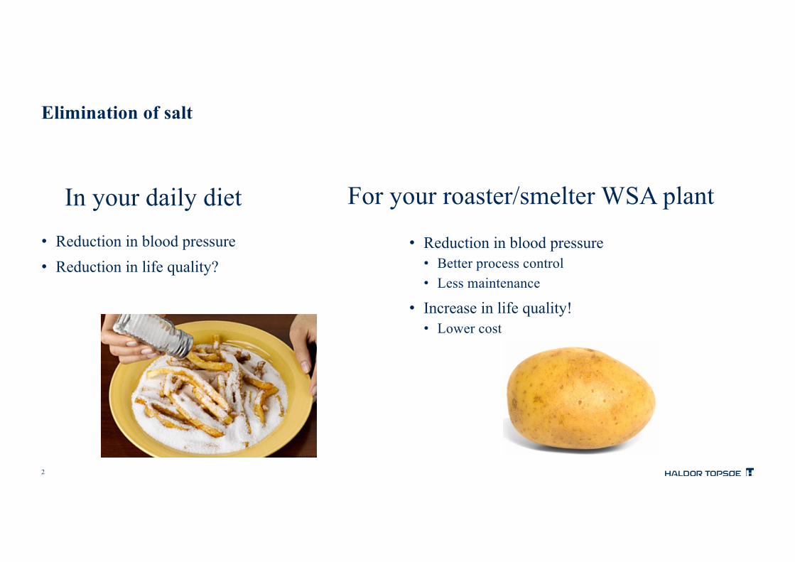
Elimination of salt
• Reduction in blood pressure• Reduction in life quality?
• Reduction in blood pressure• Better process control• Less maintenance
• Increase in life quality!• Lower cost
In your daily diet For your roaster/smelter WSA plant

3
Agenda
• The WSA process• The traditional WSA layout for roaster/smelter gases• The new salt-free WSA layout• Main control loops• What if…..
• Dynamic simulations• Pt-smelter case study• Dynamic response of the WSA plant
• Pro and cons• Economics• Conclusions

4
The WSA processWSA = Wet gas Sulfuric Acid
Concentrated H2SO4
Lean H2S gas
Rich H2S gas
SRU tail gas
SWS gas
SO2
SO3
Spent H2SO4
Elemental sulfur
CS2 / COS
WSACleaned gas
HP Steam
Waste water
> 145 WSA references- 14 in non-ferrous industry- 45 in oil refineries

5
The traditional WSA plant layoutsmelter off-gases up to 7 vol% SO2
Interbedcooler
Process gas cooler
SO2 converterFuel gas
Feed gas preheater
SO2 gas from gas cleaning plant
BFW
Salt coolerLP steam
Process gas blower
Processgas heaterStatic
mixer
Salt tank
WSA condenser
Air
Acidcooler
Cooling air blower
Cleanedgas to stack
Product acid
Coolingwater
1st VK-WSA layer
2nd VK-WSX layer

6
The new WSA plant layoutsmelter off-gases up to 7 vol% SO2
Interbedcooler
2nd Process gas cooler
SO2 converter
1st Process gas cooler
Fuel gasWSA condenser
Air
Acidcooler
Processgas heater
Feed gas preheater
SO2 gas from gas cleaning plant
BFW
SteamdrumHP Steam
export
Cooling air blower
Process gas blower
Recycle blower
Cleanedgas to stack
Product acid
Coolingwater
Static mixer
1st VK-WSA layer
2nd VK-WSX layer

7
The new WSA plant layoutMain control loops
Interbed cooler
2nd Process gas cooler
1st Process gas cooler
SO2 gas from gas cleaning plant
BFW
HP Steamexport
TIC
TIC
PICTIC
TIC
TIC
Process gas to WSA condenser
8
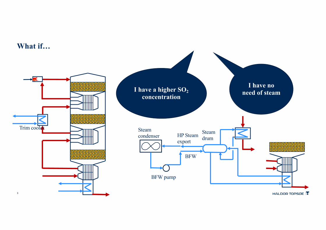
What if…
HP Steamexport
BFW pump
Steamcondenser
Steamdrum
BFW
Trim cooler
I have a higher SO2concentration
I have no need of steam

9
Dynamic simulationsFluctuating feeds from the smelters batch operations
0
1
2
3
4
5
0
10
20
30
40
0 2 4 6 8 10 12
SO2concentration[vol%]
Processg
asflow
[kNm
3 /h]
Time[h]
ProcessgasflowSO2concentration
Case study: 30,000 Nm3/h feed gas from Pt-smelter
Electric Furnace 0.5-1% vol. SO2Stable flow
Peirce-Smith converting (P-S)2-6% vol. SO2Intermittent flow (Batch operation)
Sometimes below autothermal SO2concentration of ~2 vol%
10
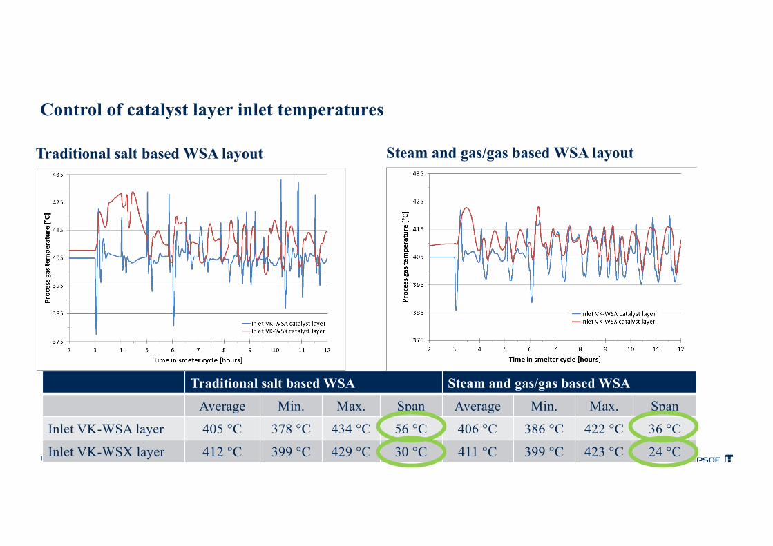
Control of catalyst layer inlet temperatures
Traditional salt based WSA layout Steam and gas/gas based WSA layout
Traditional salt based WSA Steam and gas/gas based WSA
Average Min. Max. Span Average Min. Max. Span
Inlet VK-WSA layer 405 °C 378 °C 434 °C 56 °C 406 °C 386 °C 422 °C 36 °C
Inlet VK-WSX layer 412 °C 399 °C 429 °C 30 °C 411 °C 399 °C 423 °C 24 °C

11
Control of process gas cooler temperatures
Traditional salt based WSA layout Steam and gas/gas based WSA layout
Traditional salt based WSA Steam and gas/gas based WSA
Average Min. Max. Safety Average Min. Max. Safety
Inlet PG cooler(s) 409 °C 398 °C 421 °C - 413°C 401°C 426 °C -
Outlet PG cooler(s) 275 °C 266 °C 288 °C 24 °C 266 °C 263 °C 271 °C 23 °C

12
Pro and consComparison between traditional and new layout
Traditional WSA layout New WSA layout
Heat management Eutectic salt (NaNO2/NaNO3/KNO2)
Steam (H2O) and process gas
Solidification point 145-190 °C 0 °C
Replacement Every 3-5 years Continuous
Insulation Tracing and insulation Insulation only
Maintenance Medium Low
Process control Slow Fast
Process control Stable More stable
Start-up time Long Short
SO2 conversion High High
13
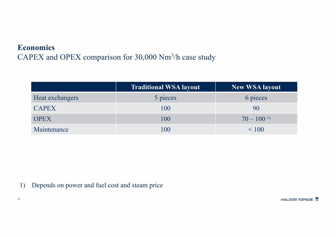
EconomicsCAPEX and OPEX comparison for 30,000 Nm3/h case study
Traditional WSA layout New WSA layoutHeat exchangers 5 pieces 6 piecesCAPEX 100 90OPEX 100 70 – 100 1)
Maintenance 100 < 100
1) Depends on power and fuel cost and steam price

14
ConclusionsTopsoe’s new combined steam and gas/gas WSA layout for SO2 smelter gases
• eliminates need for heat transfer salt• looks more complicated but is easier to operate• provides more stable process gas temperatures• has faster start-up and dynamics• is foreseen to require less maintenance• has lower hardware cost, CAPEX• has comparable (and low) OPEX• has same high SO2 conversion • is Topsoe’s preferred option


