92
B 19-E HALFEN CAST-IN CHANNELS CONCRETE
B 19-EHALFEN CAST-IN CHANNELS
CONCRETE

2
HTA-CE
© 2019 HALFEN · B 19-E · www.halfen.com
HALFEN CAST- IN CHANNELS
Contents
1 HALFEN HTA-CE Channels 7
- Application examples 4– 5- General 7 – 8- Materials / Corrosion protection 9 – 11- Installation / Assembly 11 – 12- Identification / Geometry 13 - Product range 14 – 16- HALFEN Bolts HS / HSR 17 – 21- Available types 23 – 24 - HTA-CS (Curved channels) 23- Calculation 25- Software 26 – 27- Dynamic loading 37
2 HALFEN HZA Channels 28
- Application examples 28 – 29- Product range 30 - HALFEN HZS Bolts 31 - Calculation 33 – 36- Dynamic loading 37
3 HALFEN HGB Guard rail fixings 38
- Application examples 39- General 40- Materials / Corrosion protection 41- Installation / Assembly 42- Product range 43- Dimensioning / calculation 44 – 51
4 HALFEN HTU Channels – fixings for trapezoid metal sheet 52
- Application examples 53- General / Materials 54- Installation / Assembly 55- Product range 56- Dimensioning 57
3© 2019 HALFEN · B 19-E · www.halfen.com
HALFEN CAST- IN CHANNELS
Contents
90
AccessoriesAdjustment coupler HJV
BL, BLQ brick tie anchorBrick tie anchor ML, BLBrick tie channel HMS
Cold-rolled channels HTA-CECold-rolled channels HZACorner guard HKWCorrosion protection HALFEN Channels & boltsCoupler sleeves VBM, SKMCurved HALFEN Cast-in channels HTA-CE, HZA
DowelsDYNAGRIP HALFEN Cast-in channelsDynamic Loads for HALFEN Cast-in channels
End anchor ANK-E for HALFEN Channels HTA
Firewall connection (masonry)Framing channels HM, HL,Framing channels, serrated HZM, HZL
HALFEN BoltsHALFEN Cast-in channelsHALFEN Cast-in channels; corner elementsHALFEN Framing channelsHCW Curtain Wall SystemHexagonal coupler SKMHexagonal nuts - boltsHGB Handrail connection systemsHKW Corner guardHKZ Restraint tie, serratedHL Framing channels, slottedHM Framing channelsHMS Brick tie channelsHNA Timber fixing strapsHot-rolled channels HTA-CEHot-rolled channels HZAHS HALFEN BoltsHSF Rafter shoeHSR HALFEN Bolts with nibHTA-CE HALFEN Cast-in ChannelsHTU Profiled metal sheets fixing channelsHVL Precast connectionHZA HALFEN Cast-in channel DYNAGRIPHZA HALFEN Cast-in channel, serrated HZL Framing channels, slotted
HZM Framing channels, serratedHZS HALFEN Bolts, serrated
Locking washer SIC
ML, MLQ Brick tie anchor
Nuts MU
Perforated framing channels HL, HZLPrecast connection HVLProfiled metal sheet fixing channel HTUProfiles HM, HLProfiles, serrated, HZM, HZL
Rafter shoe HSFRail clips KLPRestraint tie HKZRestraint with turnbuckle SPVRing nuts RM
Serrated profiles HZA Cast-in channelsSerrated profiles HZM, HZL Framing channelsShort & cut lengths of HALFEN ChannelsSIC Locking washerSKM Coupler sleeveSPH turnbuckle with right- and left-hand threadsSPV Restraint with turnbuckleSquare washers VUSStandard lengths for HALFEN Channels HTA-CEStandard lengths for HALFEN Channels HZA
Threaded rodsTimber fixingTurnbuckle with right- and left-hand thread SPH
VBM Coupler sleeveVUS Washer
US Washer
Washer US, VUS
Page:84–89
86
62–6562–6562, 64
16–173170
11–12, 318625
6329–37
37
24
6588–89
19–235
2588–8971–83
8685–8638–51
7067–6888–8988–8962, 64
6116–17
3119–22
6023
7–2852–57
6929–3729–3788–89
APPENDIX
Index
Page:88–8932–35
85
62–65
85
88–8969
52–5788–8988–89
6087
67–686686
29–3788–8918, 35
85868666851835
8658–61
86
8685
85
85
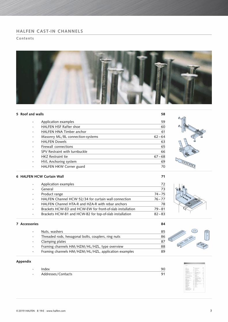
5 Roof and walls 58
- Application examples 59- HALFEN HSF Rafter shoe 60- HALFEN HNA Timber anchor 61- Masonry ML / BL connection-systems 62 – 64- HALFEN Dowels 63- Firewall connections 65- SPV Restraint with turnbuckle 66- HKZ Restraint tie 67 – 68- HVL Anchoring system 69- HALFEN HKW Corner guard 70
6 HALFEN HCW Curtain Wall 71
- Application examples 72- General 73- Product range 74 – 75- HALFEN Channel HCW 52/34 for curtain wall connection 76 – 77- HALFEN Channel HTA-R and HZA-R with rebar anchors 78- Brackets HCW-ED and HCW-EW for front-of-slab installation 79 – 81- Brackets HCW-B1 and HCW-B2 for top-of-slab installation 82 – 83
7 Accessories 84
- Nuts, washers 85- Threaded rods, hexagonal bolts, couplers, ring nuts 86- Clamping plates 87- Framing channels HM / HZM / HL / HZL, type overview 88- Framing channels HM / HZM / HL / HZL, application examples 89
Appendix
- Index 90- Addresses / Contacts 91

44
Cur
tain
Wal
lH
TU C
hann
els
Roof
and
Wal
lH
TA-C
E C
hann
els
HG
B C
hann
els
1
2
5
4
3
7
6
HZA
Cha
nnel
sA
cces
sories
© 2019 HALFEN · B 19-E · www.halfen.com
APPLICATION EXAMPLES HALFEN CAST- IN CHANNELS
Areas of Appl icat ion
CURTAIN WALL
BRIDGES
LIFTS AND ELEVATORS
Lift fixings, guide-rails
TUNNELS
Lötschberg-Base tunnel, Switzerland
POWER STATIONS
Power station
SPORTS
HTU Trapezoidal sheet panels
UPS Air Hub, Cologne Bonn Airport, Germany
ROOFS AND WALLS
Timber pitched-roof construction
Rheinenergiestadion, Cologne/Germany
Edificio Gas Natural, Barcelona/Spain
Passerelle Simone de Beauvoir, Paris/France
55
Cur
tain
Wal
lH
TU C
hann
els
Roof
and
Wal
lH
TA-C
E C
hann
els
HG
B C
hann
els
1
2
5
4
3
7
6
HZA
Cha
nnel
sA
cces
sories
© 2019 HALFEN · B 19-E · www.halfen.com
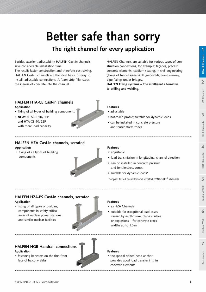
Besides excellent adjustability HALFEN Cast-in channels save considerable installation time. The result: faster construction and therefore cost saving. HALFEN Cast-in channels are the ideal basis for easy to install, adjustable connections. A foam strip filler stops the ingress of concrete into the channel.
HALFEN Channels are suitable for various types of con-struction connections, for example: façades, precast concrete elements, stadium seating, in civil engineering (fixing of tunnel signals) lift guide-rails, crane runway, pipe fixings under bridges.HALFEN Fixing systems – The intelligent alternative to drilling and welding.
Better safe than sorryThe right channel for every application
HALFEN HTA-CE Cast-in channelsApplication• fixing of all types of building components
• NEW: HTA-CE 50/30P and HTA-CE 40/22P with more load capacity.
HALFEN HZA Cast-in channels, serratedApplication• fixing of all types of building
components
HALFEN HZA-PS Cast-in channels, serratedApplication• fixing of all types of building
components in safety critical areas of nuclear power stations and similar nuclear facilities
HALFEN HGB Handrail connectionsApplication• fastening banisters on the thin front
face of balcony slabs
Features• adjustable
• hot-rolled profile; suitable for dynamic loads
• can be installed in concrete pressure and tensile-stress zones
Features• adjustable
• load transmission in longitudinal channel direction
• can be installed in concrete pressureand tensile-stress zones
• suitable for dynamic loads*
Features• as HZA Channels
• suitable for exceptional load cases caused by earthquake, plane crashes or explosions – for concrete crack widths up to 1.5 mm
Features• the special ribbed head anchor
provides good load transfer in thin concrete elements
*applies for all hot-rolled and serrated DYNAGRIP® channels

66
Cur
tain
Wal
lH
TU C
hann
els
Roof
and
Wal
lH
TA-C
E C
hann
els
HG
B C
hann
els
1
2
5
4
3
7
6
HZA
Cha
nnel
sA
cces
sories
© 2019 HALFEN · B 19-E · www.halfen.com
A part from excellent adjustability, HALFEN Cast-in channels save
considerable installation time. The result: faster construction and therefore reduced overall cost.
HALFEN HTA-CE Channelshot-rolled
Quick and economical
• adjustable anchoring
• bolts instead of welding
• maximum efficiency when installingmatrices and rows
• cost effective installation usingstandard tools
• optimised pre-planning reduces construction time
• large range of types available forvarious requirements
• no noise, no vibration during installa-tion, therefore no health hazards
Safe and reliable
• no damage to the reinforcement
• approved for fire-resistant structural elements
• suitable for use in concrete pressure and tensile stress zones
• high corrosion resistance steels available
• suitable for dynamic loads
• European TechnicalAssessment (ETA)
• precise calculation with HALFEN Software
HALFEN HTA-CE Channelscold-rolled
HALFEN HTA-CE Cast-in channelsThe advantages at a glance
suitable for dynamic loads
European Technical Assessment ETA -09/0339
77
NR,s,a NR,c,p VR,s,s VR,cp
VR,cVR,s,c
VR,s,a
VR,s,l
NR,c
NR,sp
NR,cb
NR,s,c
NR,s,l
NR,s,s
MR,s,flexC
urta
in W
all
HTU
Cha
nnel
sRo
of a
nd W
all
HTA
-CE
Cha
nnel
sH
GB
Cha
nnel
s
1
2
5
4
3
7
6
HZA
Cha
nnel
sA
cces
sories
© 2019 HALFEN · B 19-E · www.halfen.com
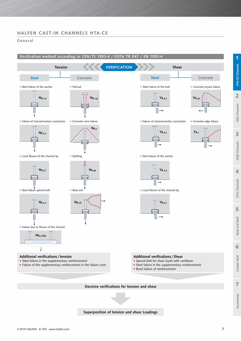
HALFEN CAST- IN CHANNELS HTA -CE
Genera l
Verification method according to CEN/TS 1992-4 / EOTA TR 047 / EN 1992-4
Tension
Steel SteelConcrete Concrete
Shear
Additional verifications / tension▸ Steel failure in the supplementary reinforcement▸ Failure of the supplementary reinforcement in the failure cone
Decisive verifications for tension and shear
Additional verifications / Shear▸ Special bolt for shear loads with cantilever▸ Steel failure in the supplementary reinforcement▸ Bond failure of reinforcement
Superposition of tension and shear Loadings
VERIFICATION
▸ Steel failure of the anchor
▸ Steel failure of the anchor
▸ Pull-out
▸ Failure of channel-anchor connection ▸ Failure of channel-anchor connection▸ Concrete cone failure ▸ Concrete edge failure
▸ Concrete pryout failure
▸ Splitting
▸ Blow-out
▸ Local flexure of the channel lip
▸ Local flexure of the channel lip▸ Steel failure special bolt
▸ Steel failure of the bolt
▸ Failure due to flexure of the channel
88
www.dnvgl.com
BIM
© 2019 HALFEN · B 19-E · www.halfen.com
Cur
tain
Wal
lH
TU C
hann
els
Roof
and
Wal
lH
TA-C
E C
hann
els
HG
B C
hann
els
1
2
5
4
3
7
6
HZA
Cha
nnel
sA
cces
sories
HALFEN HTA -CE CAST- IN CHANNELS
Genera l in format ion
Fire-resistance/ Material fatigue
Quality is the outstanding feature of our products. HALFEN materials and products are subjected to the most stringent quality control procedures. A quality inspection by the DNV GL* has verified that our quality management system meets the requirements of the ISO 9001:2015 standard.
*merger of DNV (Det Norske Veritas) and GL (Germanischer Lloyd) in 2013
Quality
An EPD® (Environmental Product Declaration) provides transparent and comparable ecological data which helps to evaluate the sustainability of a building. Already during the planning phase the data provided here is of great significance for architects and planners. The data provided also helps to ensure the high demands on the environmental performance of the building are met.Health Product Declarations abbreviation = HPD, complement our information on sustainability. The HPDs includes a list of all components and information on the health effects of these components. The new HPD for hot-dip galvanized HALFEN Cast-in channels helps to achieve additional points in the Leed-v4-system.www.halfen.com ► ► Brochures ► ► Product declarations.
Green building EPD+HPD
HALFEN already has considerable experience as a BIM partner and has successfully completed various projects using the BIM methodology. All HALFEN engineers are trained to properly supervise this process. With a combination of wide experience and highly-trained engineers the increasing demand for BIM projects can be efficiently met. Examples of previous projects developed using BIM can be found at www.halfen.com ► ► Service ► ► BIM ► ► BIM references.
BIM
Certificate no. 202384-2016-AQ-GER-DAkkS
ETA-09/0339 contains characteristic values under fire stress according to TR 020 "Evalu-ation of anchorages in concrete with regard to fire resistance" as well as characteristic values for fatigue stress.
Approvals on the internetCurrently valid approvals can be found at: www.halfen.com ►► Brochures ►► Approvals ►► Fixing systems. Or simply scan the code and select the required document.
99
HALFEN Cast-in channels, steel, hot-dip galvanized
Steel
Material Standard Zinc coat
Channel profile1.0038 EN 10 025-2 FV: ≥ 55 μm
1.0044 EN 10 025-2 FV: ≥ 55 μm
Bolt anchor B6 Steel EN 10263 or EN 10269 FV: ≥ 55 μm
Weld-on anchor Steel EN 10 025-2 FV: ≥ 55 μm
HALFEN Bolts, galvanized steel
Steel
Material Standard Zinc coat
Bolt Steel (Sc) 4.6 or (Sc) 8.8 EN ISO 898-1FV: ≥ 50 μm
GVs: ≥ 12 μm
Hexagonal nut Steel (Sc) 5 or (Sc) 8 EN 898-2FV: ≥ 50 μm
GVs: ≥ 12 μm
Washer Steel EN ISO 7089,EN ISO 7093
FV: ≥ 50 μm
GVs: ≥ 12 μm
HALFEN Cast-in channels, stainless steel
Stainless steel
Material StandardCorrosion
resistance class
Channel profile1.4404 or 1.4571
EN 10 088III
1.4529 or 1.4547 V
Bolt anchor B61.4404, 1.4571 or 1.4578 EN 10 088
III
1.4529 or 1.4547 V
Weld-on anchor1.4404 or 1.4571 EN 10 088 III
Steel EN 10 025-2
HALFEN Bolts, stainless steel
Stainless steel
Material StandardCorrosion
resistance class
Bolt1.4404, 1.4571, 1.4578 (A4-50 or A4-70)
EN 3506-1 and EN 10 088 III
1.4529, HCR-50 EN 3506-1 V
Hexagonal nut1.4404, 1.4571, 1.4578 (A4-50, A4-70) EN 3506-2 and
EN 10 088III
1.4529, HCR-50 V
Washer1.4404, 1.4571
EN 10 088III
1.4529 or 1.4547 V
(Sc) = Strength class
© 2019 HALFEN · B 19-E · www.halfen.com
Cur
tain
Wal
lH
TU C
hann
els
Roof
and
Wal
lH
TA-C
E C
hann
els
HG
B C
hann
els
1
2
5
4
3
7
6
HZA
Cha
nnel
sA
cces
sories
HALFEN HTA -CE CAST- IN CHANNELS
Mater ia ls / Corros ion Protect ion
See EN 1993-1-4, table A.3 Corrosion protection of mill finished anchor, see page 12
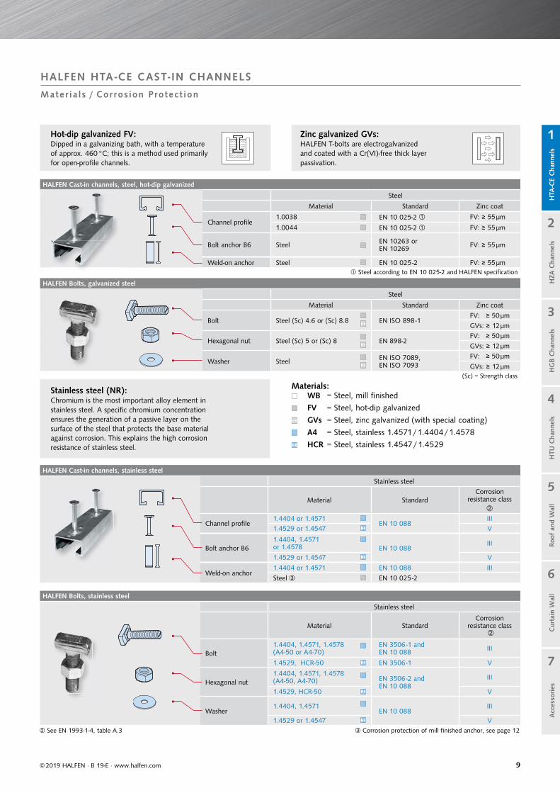
Zinc galvanized GVs:HALFEN T-bolts are electrogalvanized and coated with a Cr(VI)-free thick layer passivation.
Stainless steel (NR):Chromium is the most important alloy element in stainless steel. A specific chromium concentration ensures the generation of a passive layer on the surface of the steel that protects the base material against corrosion. This explains the high corrosion resistance of stainless steel.
WB = Steel, mill finished
FV = Steel, hot-dip galvanized
GVs = Steel, zinc galvanized (with special coating)
A4 = Steel, stainless 1.4571/1.4404/1.4578
HCR = Steel, stainless 1.4547/1.4529
Materials:
Hot-dip galvanized FV:Dipped in a galvanizing bath, with a temperature of approx. 460 °C; this is a method used primarily for open-profile channels.
Steel according to EN 10 025-2 and HALFEN specification
1010
Material and applications1 2 3 4
Description Dry interior rooms Damp interior rooms Medium corrosion level High level of corrosion
Definition of application areas
Anchor channels may only be used in components in indoor environments.
For example:living and office spaces, schools; hospitals, commercial shops with the exception of wet rooms as in column 2.
Anchor channels may also be used in components in areas with normal humidity
For example:kitchens, bathrooms and laundry-rooms in residential buildings. Exceptions: where permanent steamis present, and under water.
Anchor channels may also be used in outdoor environments (including industrial environ-ments and coastal regions) or in wet rooms, if condi-tions are not especially aggressive (for example: continual immersion in sea water etc. as in column 4).
Anchor channels may also be used in exceptionally aggressive environments (for example: continual immersion in sea water) or in seawater spray zones, chloride environments in swim-ming pools or in environments with an extremely aggressive chemical atmosphere (for example: flue gas desulphurization plants or road tunnels where de-icer systems are in use).
Channel profile Steel 1.0038, 1.0044; EN 10025 Hot-dip galvanized≥ 55 m
Steel 1.0038, 1.0044; EN 10025 Hot-dip galvanized ≥ 55 μm Stainless steel 1.4307, 1.4567, 1.4541; EN 10088
Stainless steel1.4404, 1.4571,1.4062, 1.4162, 1.4362 EN 10088
Stainless steel 1.4462 , 1.4529, 1.4547EN 10088
Anchor Steel 1.0038, 1.0214, 1.0401, 1.1132, 1.5525; EN 10263, EN 10269Hot-dip galvanized 55 m
Steel 1.0038, 1.0214, 1.0401, 1.1132, 1.5525; EN 10263, EN 10269Hot-dip galvanized ≥ 55 μm Stainless steel 1.4307, 1.4567, 1.4541; EN 10088
Stainless steel1.4404, 1.4571, 1.4362, 1.4578 EN 10088Mill finish, 1.0038
Special HALFEN Bolts with shaft and bolts in accordance with EN ISO 4018
Steel strength class 4.6 / 8.8EN ISO 898-1Zinc galvanized ≥ 5 m
Steel strength class 4.6 / 8.8; EN ISO 898-1, Hot-dip galvanized ≥ 50 μm Stainless steel, strength class 50, 70 1.4307, 1.4567, 1.4541EN ISO 3506-1
Stainless steelStrength class 50, 701.4404, 1.4571, 1.4362, 1.4578 EN ISO 3506-1
Stainless steel Strength class 50, 701.4462 , 1.4529, 1.4547 EN ISO 3506-1
Washers EN ISO 7089 and EN ISO 7093-1 Product classification A, 200 HV
Steel EN 10025Zinc galvanized 5 m
Steel EN 10025Hot-dip galvanized ≥ 50 μm Stainless steelSteel grade A2, A3; EN ISO 3506-1
Stainless steelSteel grade A4, A5EN ISO 3506-1
Stainless steel 1.4462 ,1.4529, 1.4547 EN ISO 3506-1
Hexagonal nut EN ISO 4032
Steel strength class 5/8EN ISO 898-2Zinc galvanized 5 m
Steel strength class 5/8 EN ISO 898-2Hot-dip galvanized ≥ 50 μm Stainless steel, strength class 70, 80 Steel grade A2, A3 EN ISO 3506-2
Stainless steelStrength class 70, 80Steel grade A4, A5EN ISO 3506-2
Stainless steel Strength class 70, 801.4462 , 1.4529, 1.4547 EN ISO 3506-2
or zinc galvanized with special coating ≥ 12 m 1.4462 not suitable for swimming baths Steel in accordance with EN 10025, 1.0038 not for anchor channels 28/15 and 38/17
Zinc galvanized in accordance with EN ISO 4042 Hot-dip galvanized in accordance with EN ISO 10684 Hot-dip galvanized in accordance with EN ISO 1461
Corrosion protection requirements
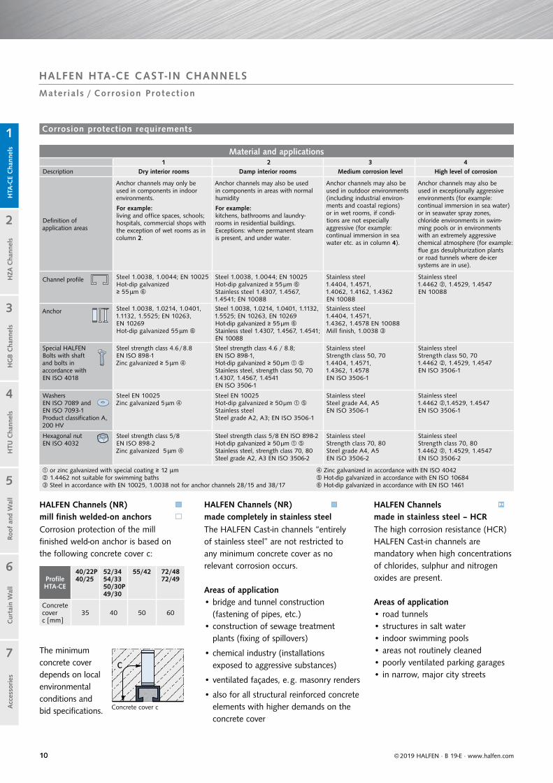
Profile HTA-CE
40/22P40/25
52/3454/3350/30P49/30
55/42 72/4872/49
Concrete cover c [mm]
35 40 50 60
c
© 2019 HALFEN · B 19-E · www.halfen.com
Cur
tain
Wal
lH
TU C
hann
els
Roof
and
Wal
lH
TA-C
E C
hann
els
HG
B C
hann
els
1
2
5
4
3
7
6
HZA
Cha
nnel
sA
cces
sories
HALFEN HTA -CE CAST- IN CHANNELS
Mater ia ls / Corros ion Protect ion
Concrete cover c
The HALFEN Cast-in channels “entirely of stainless steel” are not restricted to any minimum concrete cover as no relevant corrosion occurs.
Areas of application• bridge and tunnel construction
(fastening of pipes, etc.) • construction of sewage treatment
plants (fixing of spillovers)
• chemical industry (installations exposed to aggressive substances)
• ventilated façades, e. g. masonry renders
• also for all structural reinforced concrete elements with higher demands on the concrete cover
Corrosion protection of the mill finished weld-on anchor is based on the following concrete cover c:
The minimum concrete cover depends on local environmental conditions and bid specifications.
The high corrosion resistance (HCR) HALFEN Cast-in channels are mandatory when high concentrations of chlorides, sulphur and nitrogen oxides are present.
Areas of application• road tunnels• structures in salt water• indoor swimming pools• areas not routinely cleaned• poorly ventilated parking garages• in narrow, major city streets
HALFEN Channels (NR) made completely in stainless steel
HALFEN Channels (NR) mill finish welded-on anchors
HALFEN Channels made in stainless steel – HCR
1111
HTA-CE 38/17
≤ 200 (250)
25–3525
Cur
tain
Wal
lH
TU C
hann
els
Roof
and
Wal
lH
TA-C
E C
hann
els
HG
B C
hann
els
1
2
5
4
3
7
6
HZA
Cha
nnel
sA
cces
sories
© 2019 HALFEN · B 19-E · www.halfen.com
1.2
2.1
HALFEN HTA -CE CAST- IN CHANNELS
Ins ta l la t ion/Assembly
2.2
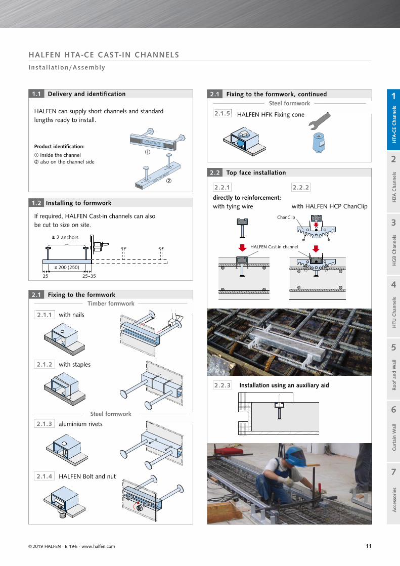
Delivery and identification
Top face installation
HALFEN can supply short channels and standard lengths ready to install.
1.1
2.2.1 2.2.2
2.2.3 Installation using an auxiliary aid
directly to reinforcement: with tying wire with HALFEN HCP ChanClip
ChanClip
HALFEN Cast-in channel
Fixing to the formwork
Fixing to the formwork, continued
2.1
2.1.4
2.1.5
HALFEN Bolt and nut
HALFEN HFK Fixing cone
2.1.3 aluminium rivets
2.1.1 with nails
2.1.2 with staples
Steel formwork
Timber formwork
2 1 3 aluminium riv
St
2 1 1 ith il
Ti
Installing to formwork
If required, HALFEN Cast-in channels can also be cut to size on site.
≥ 2 anchors
Product identification:
inside the channel also on the channel side
2 1 5 HALFEN HFK
Steel formwork

1212
HTA-CE
-KF
[Nm]T inst
Cur
tain
Wal
lH
TU C
hann
els
Roof
and
Wal
lH
TA-C
E C
hann
els
HG
B C
hann
els
1
2
5
4
3
7
6
HZA
Cha
nnel
sA
cces
sories
© 2019 HALFEN · B 19-E · www.halfen.com
HALFEN HTA -CE CAST- IN CHANNELS
Ins ta l la t ion/Assembly
Installing HALFEN Bolts4.1
Safe assembly with HALFEN Cast-in channelsHALFEN Bolts can be inserted anywhere in the channel slot, turned 90° and then locked in place by tightening the nut. Do not position bolts at channel ends past the last anchor. On channels with bolt anchors, the anchor locations are visible through the channel slot.
FixingsThe bolt heads must sit flush on both lips of the anchor channel and be secured by tightening the nut with a torque wrench with the required value. Observe the torque values in the tables on page 21.
CheckBolts: After installation check that the bolts are properlyaligned; the notch or notches in the tip of the shank mustbe at right angles to the longitudinal axis of the channel.
Strip filler, available in two versions: Removing the strip fillerGrip the strip filler at one end and pull out in one piece by hand, use a tool, e. g. a screwdriver.
Bolt HS,non-serrated
Bolt HSRserrated or with nib
or
Surface-flush installation Non-flush installation
If the front surface of the channel is set back from the concrete sur-face, the attached structure must be shimmed with a washer (VUS).In case of shear stress, add bolt flexure to the tensile force.
Example: HALFEN Channel: HTA-CE 49/30HALFEN Bolt: HS 50/30 - M16 Washer: VUS 49/30 - M16
Square washer VUS Square washer VUS
Direct attachment
Always install a square washerfor stand-off installations.
Stand-off installation
Assembly instructions on the internetMulti-language assembly instructions can be found at www.halfen.com ►► Brochures ►► Installation Instructions. Or scan the code and select the required document.
KF – PE strip fi ller with reinforcement layer
Removing the filler3.1
KF – PE strip fi ller

1313
Channel material Type identification
1.0038 / 1.0044 HTA-CE 38/17
A2: 1.4307 HTA-CE 38/17 - A2
A4: 1.4404 / 1.4571 HTA-CE 38/17 - A4
HCR: 1.4529 / 1.4547 HTA-CE 38/17 - HCR
Edge and bolt spacing [mm]
HTA-CE Profiles M ss,min cmin emin
28/15
6 30 40 15
8 40 40 15
10 50 40 15
12 60 40 15
38/17
10 50 50 25
12 60 50 25
16 80 50 25
40/2540/22P
10 50 50 25
12 60 50 25
16 80 50 25
49/30
10 50 75 50
12 60 75 50
16 80 75 50
20 100 75 50
50/30P
10 50 75 40
12 60 75 40
16 80 75 40
20 100 75 40
52/3454/33
10 50 100 65
12 60 100 65
16 80 100 65
20 100 100 65
55/42
10 50 100 65
12 60 100 65
16 80 100 65
20 100 100 65
72/48
20 100 150 115
24 120 150 115
27 135 150 115
30 150 150 115
© 2019 HALFEN · B 19-E · www.halfen.com
Cur
tain
Wal
lH
TU C
hann
els
Roof
and
Wal
lH
TA-C
E C
hann
els
HG
B C
hann
els
1
2
5
4
3
7
6
HZA
Cha
nnel
sA
cces
sories
Anchors must be installed at a minimum distance from the component edges. The distance depends on the selected channel profile. Full steel capacity not necessarily achieved; please verify using free to download software. According to the ETA, the spacing between bolts scbo must not be less than 5 × ds. Reduction of the load bearing capacity is required if scbo < ssl,N* (see table on page 16).
*ssl,N = centre distance of the bolts NRd,s,l
Type identification: Inside on the bottom of the channel. Additionally on the channel side
HALFEN HTA -CE CAST- IN CHANNELS
Ident i f i cat ion / Geometr y
Identification
e2,1
c2,1
c1,2
c1,1
h
scbo
scbo
c2,2
e2,2
NE,1
VE,1
VE,2
NE,2
Minimum edge distances and minimum bolt spacing
Figure: Minimal edge and bolt spacings

1414
Identification values HTA-CE
Profile HTA-CE 72/48 HTA-CE 55/42 HTA-CE 52/34 HTA-CE 50/30P HTA-CE 40/22P
Type hot-rolled hot-rolled hot-rolled hot-rolled hot-rolled
Materialmaterialdescription:
see page 10
Steel
A4
HCR
Bolts HS 72/48 HS 50/30 HS 50/30 HS 50/30 HS 40/22
Threads M 20–M30 M 10–M 20 M 10–M 20 M 10–M 20 M 10–M 16
sl,N [mm] 144 109 105 98 79
Profile load capacity*
N0Rd, s, l [kN] 66.7 61.1 40.0 23.9 21.1
V0Rd, s, l [kN] 81.1 61.1 43.5 32.8 19.4
MRd, s, flex [Nm]
Steel7472 5606 2933 2437 1208
NR
Geometry
hnom [mm] (191) 182 (185) 162 (164) 112 (161) 97 (154)
bch [mm] 72 54.5 52.5 49 39.5
hch [mm] 48.5 42 33.5 30 23
Iy [mm4] Steel349721 187464 93262 52896 20029
NR
hef [mm] 179 175 155 106 91
cmin [mm] 150 100 100 75 50
* Concrete load capacity has to be verified for each individual case (taking the geometric boundary conditions into account).
cmin = minimal spacing channel/concrete edgeNR = Stainless steelsslb = axial spacing for bolts for N0
Rd,s,l
N0Rd,s,l = channel lip load capacity (tension)
V0Rd,s,l = channel lip load capacity (shear)
Nominal size and tolerance( ) value in brackets is for weld-on
I - anchors
49
30 23
18
72
33
42
26
i
Cur
tain
Wal
lH
TU C
hann
els
Roof
and
Wal
lH
TA-C
E C
hann
els
HG
B C
hann
els
1
2
5
4
3
7
6
HZA
Cha
nnel
sA
cces
sories
© 2019 HALFEN · B 19-E · www.halfen.com
HALFEN HTA -CE CAST- IN CHANNELS
Product Range: Overview of Channels + Bolts
22.5 7.8
39.5
6.0
GeometryHALFEN HTA-CE Channels
bch
dch
h nom h e
f
h ch
f
Note: observe theinstallation heighthnom
48.5
15.5
12.9 22.5
33.5
10.5
52.554.5
y
1515
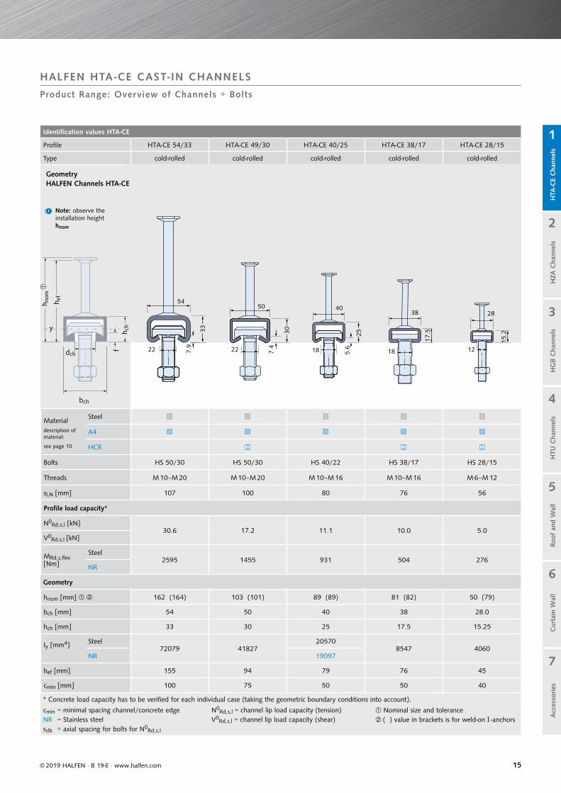
Identification values HTA-CE
Profile HTA-CE 54/33 HTA-CE 49/30 HTA-CE 40/25 HTA-CE 38/17 HTA-CE 28/15
Type cold-rolled cold-rolled cold-rolled cold-rolled cold-rolled
Materialdescription of material:
see page 10
Steel
A4
HCR
Bolts HS 50/30 HS 50/30 HS 40/22 HS 38/17 HS 28/15
Threads M 10–M 20 M 10–M 20 M 10–M 16 M 10–M 16 M 6–M 12
sl,N [mm] 107 100 80 76 56
Profile load capacity*
N0Rd, s, l [kN]
30.6 17.2 11.1 10.0 5.0V0
Rd, s, l [kN]
MRd, s, flex [Nm]
Steel2595 1455 931 504 276
NR
Geometry
hnom [mm] 162 (164) 103 (101) 89 (89) 81 (82) 50 (79)
bch [mm] 54 50 40 38 28.0
hch [mm] 33 30 25 17.5 15.25
Iy [mm4] Steel72079 41827
205708547 4060
NR 19097
hef [mm] 155 94 79 76 45
cmin [mm] 100 75 50 50 40
* Concrete load capacity has to be verified for each individual case (taking the geometric boundary conditions into account).
cmin = minimal spacing channel/concrete edgeNR = Stainless steelsslb = axial spacing for bolts for N0
Rd,s,l
N0Rd,s,l = channel lip load capacity (tension)
V0Rd,s,l = channel lip load capacity (shear)
Nominal size and tolerance( ) value in brackets is for weld-on I - anchors
50
30
22 1825
402838
1218
33
22
i
Cur
tain
Wal
lH
TU C
hann
els
Roof
and
Wal
lH
TA-C
E C
hann
els
HG
B C
hann
els
1
2
5
4
3
7
6
HZA
Cha
nnel
sA
cces
sories
© 2019 HALFEN · B 19-E · www.halfen.com
HALFEN HTA -CE CAST- IN CHANNELS
Product Range: Overview of Channels + Bolts
7.4
5.6
15.2
17.5
GeometryHALFEN Channels HTA-CE
bch
dch
f
Note: observe theinstallation heighthnom
54
7.9
y
h nom
h ef
h ch

1616
Supplied lengths and number of anchors
Length [mm] / Number of anchors
HTA-CE72/48
HTA-CE55/42
HTA-CE40/25, 50/30P, 49/30,
52/34, 54/33
HTA-CE40/22P
HTA-CE28/15, 38/17
150 / 2 150 / 2 150 / 2 150 / 2 100 / 2
200 / 2 200 / 2 200 / 2 200 / 2 150 / 2
250 / 2 250 / 2 250 / 2 250 / 2 200 / 2
300 / 2 300 / 2 300 / 2 300 / 2 250 / 2
350 / 3 350 / 3 350 / 3 350 / 3 300 / 3
400 / 3 400 / 3 400 / 3 400 / 3 350 / 3
550 / 3 550 / 3 550 / 3 550 / 3 450 / 3
1050 / 5 1050 / 5 800 / 4 800 / 4 550 / 4
6070/25 6070/25 1050 / 5 1050 / 5 850 / 5
3030/13 1300 / 6 1050 / 6
6070/25 1550 / 7 3030/16
1800 / 8 6070/31
2050 / 9
2300/10
2550/11
3030/13
6070/25
Anchor spacing ≤ 250 mm
Anchor spacing ≤ 200 mm
Does not apply to HTA-CE 52/34, HTA-CE 54/33 Does not apply to HTA-CE 40/22P - A4
© 2019 HALFEN · B 19-E · www.halfen.com
Cur
tain
Wal
lH
TU C
hann
els
Roof
and
Wal
lH
TA-C
E C
hann
els
HG
B C
hann
els
1
2
5
4
3
7
6
HZA
Cha
nnel
sA
cces
sories
HALFEN HTA -CE CAST- IN CHANNELS
Product Range
The standard HALFEN Cast-in channel product range with European Technical Approval is listed in the following table. See also current HALFEN Price list.
Other lengths are available on request.
Standard product range

1717
Dimensions Vmin
Bolt diameter vmin [mm]
M6 11.0
M8 12.5
M10 14.5
M12 17.0
M16 20.5
M20 26.0
M24 29.0
M27 31.5
M30 33.5
Lip dimensions f
Channel profile f [mm]
28/15 2.3
38/17 3.0
40/22P 6.0
40/25 5.6
49/30 7.4
50/30P 7.9
52/34 10.5
54/33 7.9
55/42 12.9
72/48 15.5
Design resistance
Material / Strength class M 6 M 8 M 10 M 12 M 16 M 20 M 24 M 27 M 30
4.6
NRd,s,s [kN] 4.0 7.3 11.6 16.9 31.4 49.0 70.6 91.8 112.2
VRd,s,s [kN] 2.9 5.3 8.3 12.1 22.6 35.2 50.7 66.0 80.6
M0Rd,s,s [Nm] 3.8 9.0 17.9 31.4 79.8 155.4 268.9 398.7 538.7
8.8
NRd,s,s [kN] 10.7 19.5 30.9 44.9 83.7 130.7 188.3 244.8 299.2
VRd,s,s [kN] 6.4 11.7 18.6 27.0 50.2 78.4 113.0 146.9 179.5
M0Rd,s,s [Nm] 9.8 24.0 47.8 83.8 213.1 415.4 718.4 1065.2 1439.4
A4-50
NRd,s,s [kN] 3.5 6.4 10.1 14.8 27.4 42.8 61.7 80.2 98.1
VRd,s,s [kN] 2.5 4.6 7.3 10.6 19.8 30.9 44.5 57.9 70.7
M0Rd,s,s [Nm] 3.2 7.9 15.7 27.5 70.0 136.3 235.8 349.7 472.5
A4-70
NRd,s,s [kN] 7.5 13.7 21.7 31.6 58.8 91.7 132.1 171.8 210.0
VRd,s,s [kN] 5.4 9.9 15.6 22.7 42.2 66.0 95.1 123.6 151.0
M0Rd,s,s [Nm] 6.9 16.8 33.5 58.8 149.4 291.3 503.7 746.9 1009.2
fixt vmin
h
f
H 4.6HALFEN4.6
H 4.6HALFENHCR50
H 4.6HALFENA4-70
© 2019 HALFEN · B 19-E · www.halfen.com
Cur
tain
Wal
lH
TU C
hann
els
Roof
and
Wal
lH
TA-C
E C
hann
els
HG
B C
hann
els
1
2
5
4
3
7
6
HZA
Cha
nnel
sA
cces
sories
HALFEN HTA -CE CAST- IN CHANNELS
HALFEN HS Bol ts
Standard HALFEN Bolts (no nib or serration) for all profile types HTA-CE
H 4.6H 4.6HALFEN4.6
Manufacturer
Strength class resp. property class
(for individual dimensions)
Bolt design values
NRd,s,s is the resistance against tension loads, VRd,s,s is the the resistance against shear loads and M0
Rd,s,s is the flexural resistance when subjected to transverse load induced with a cantilever.
The table on the right lists the design resistance of HALFEN Bolts with different thread diameters, materials and strength classes.
lreq = required bolt lengthtfix = thickness of clamped componentf = profile lip height
h = washer thicknessvmin = nut height EN ISO 4032 + overhang approximately 5 mm (for M20: 7 mm)
lreq = tfix + f + h + vmin
HALFEN Bolts — Type HS
• two direction load capacity• identified on bolt tip with 1 notch
Strength class 4.6 / 8.8galvanized (GVs) or hot-dip galvanized (FV)
Material grade A4 - 50 / A4 - 70Stainless steel
Strength class 50Stainless steel (1.4529/1.4547)
Calculating the bolt length lreq for HALFEN Bolts
HALFEN Bolt
lreq

1818
HALFEN HS Bolts
Suitable for profile HTA-CE 72/48 HTA-CE 55/42, 52/34, 54/33, 50/30P, 49/30
Bolt HS 72/48 HS 50/30
Bolt dimensions
l [mm] M 20 M 24 M 27 M 30 M 10 M 12 M 16 M 20
30
- - - - FV4.6 - - -- - - - GVs4.6 GVs4.6 GVs4.6 -- - - - - - - -- - - - - - A4-50 -- - - - - A4-70 - -
40
- - - - - FV4.6 FV4.6 -- - - - - - - -- - - - GVs4.6 GVs4.6 GVs4.6 -- - - - - - GVs8.8 -- - - - - - A4-50 -- - - - - A4-70 - -
45- - - - - - - GVs4.6- - - - - GVs8.8 - GVs8.8- - - - - - - A4-50
50
FV4.6 FV4.6 - - - - FV4.6 -- - - - GVs4.6 GVs4.6 GVs4.6 -- - - - - - GVs8.8 -- A4-50 - - - - A4-50 -- - - - - A4-70 - -- - - - - - HCR-50* -
55
- - - - - - - FV4.6- - - - - - - GVs4.6- - - - - - - A4-50- - - - - - - A4-70*
60
- - - - - FV4.6 - -FV8.8 - - - - FV8.8* FV8.8 -
- - - - - GVs4.6 GVs4.6 -- - - - - GVs8.8 GVs8.8 GVs8.8- - - - - - A4-50 -- - - - - - - -
70 - - - - - - - -
75
FV4.6 FV4.6 FV4.6 FV4.6 - - - -- FV8.8 - - - - - -- - - - - - - GVs4.6
GVs8.8 - - - - - - -- - - - - - - A4-50- - - - - - - A4-70*
80
- - - - - - - FV4.6*- - - - - FV8.8* FV8.8* -- - - - - GVs4.6 GVs4.6 -- - - - - GVs8.8 GVs8.8 GVs8.8- - - - - - A4-50 -- - - - - - - -
100
FV4.6 FV4.6 - FV4.6 - - FV4.6 FV4.6- - FV8.8 - - - - -- - - - - GVs4.6 GVs4.6 GVs4.6
GVs8.8 GVs8.8 - - - - GVs8.8 GVs8.8- A4-50 - - - A4-50 - A4-50- - - - - - - A4-70*- - - - - - HCR-50* -
125 - - - - - GVs4.6 GVs4.6 GVs4.6- - - - - - - A4-50*
150
FV4.6 FV4.6 - FV4.6 - - FV4.6 -- - - - - GVs4.6 GVs4.6 GVs4.6- GVs8.8 - - - - GVs8.8- - - - - - A4-50 A4-50*- - - - - - HCR-50* -
200FV4.6 FV4.6 - FV4.6 - - - -
- - - - - GVs4.6 GVs4.6 GVs4.6- - - - - - - -
300 - - - - - - GVs4.6 GVs4.6*
Material types: see page 10 *on request i Other bolt lengths and materials on request!
58
l l
42.5
Cur
tain
Wal
lH
TU C
hann
els
Roof
and
Wal
lH
TA-C
E C
hann
els
HG
B C
hann
els
1
2
5
4
3
7
6
HZA
Cha
nnel
sA
cces
sories
© 2019 HALFEN · B 19-E · www.halfen.com
HALFEN HTA -CE CAST- IN CHANNELS
HALFEN HS Bol ts

1919
Suitable for profile HTA-CE 40/22P, 40/25 HTA-CE 38/17 HTA-CE 28/15
Bolt HS 40/22 HS 38/17 HS 28/15
Bolt dimensions
l [M ] M 10 M 12 M 16 M 10 M 12 M 16 M 6 M 8 M 10 M 12
30
- FV4.6 - FV4.6 FV4.6 - - - FV4.6 -GVs4.6 GVs4.6 GVs4.6 GVs4.6 GVs4.6 GVs4.6 GVs4.6 GVs4.6 GVs4.6 GVs4.6
- GVs8.8 - - - - - - - -- A4-50 A4-50 - - A4-50 - - - -
A4-70 - - A4-70 A4-70 - - A4-70 A4-70 -
40
- - - - - FV4.6 - - - -- - - - - - - - FV8.8 -
GVs4.6 GVs4.6 GVs4.6 GVs4.6 GVs4.6 GVs4.6 GVs4.6 GVs4.6 GVs4.6 -- GVs8.8 - - - - - - - -- A4-50 - - - A4-50 - - - -
A4-70 A4-70 - - A4-70 - - - A4-70 -
45- - - - - - - - - -- - - - - - - - - -- - - - - - - - - -
50
- FV4.6 FV4.6 FV4.6 FV4.6 FV4.6 - - FV4.6 -GVs4.6 GVs4.6 GVs4.6 GVs4.6 GVs4.6 GVs4.6 - GVs4.6 GVs4.6 GVs4.6
- - - - - - - - - -- A4-50 A4-50 - - A4-50 - - A4-50 -
A4-70 - A4-70 - A4-70 - - - - -- - - HCR-50* - HCR-50* - - HCR-50* -
55
- - - - - - - - - -- - - - - - - - - -- - - - - - - - - -- - - - - - - - - -
60
- FV4.6 FV4.6 - - - - - - -- FV8.8* FV8.8 - - FV8.8 - - - -
GVs4.6 GVs4.6 GVs4.6 GVs4.6 GVs4.6 GVs4.6 - GVs4.6 GVs4.6 -- GVs8.8 GVs8.8 - GVs8.8 - - - - -- - - - - A4-50 - - - -- - - - A4-70 - - - A4-70* -
70 - - - - FV8.8 - - - - -
75
- - - - - - - - - -- - - - - - - - - -- - - - - - - - - -- - - - - - - - - -- - - - - - - - - -- - - - - - - - - -
80
- FV4.6 - - - FV4.6 - - - -- - - - - - - - - -
GVs4.6 GVs4.6 GVs4.6 GVs4.6 GVs4.6 GVs4.6 - GVs4.6 GVs4.6 GVs4.6- GVs8.8 GVs8.8 - - - - - - -- A4-50 A4-50 - - A4-50 - - - -- - - - A4-70 - - - A4-70 -
100
- - FV4.6 - - FV4.6 - - - -- - - - - - - - - -
GVs4.6 GVs4.6 GVs4.6 GVs4.6 GVs4.6 GVs4.6 - GVs4.6 GVs4.6 -- GVs8.8 - - - - - - - -- - A4-50 - A4-50 - - - A4-50* -- - - - - - - - - -- - - HCR-50* - HCR-50* - - HCR-50* -
125 - GVs4.6 GVs4.6 - GVs4.6 GVs4.6 - - GVs4.6 -- - - - - - - - A4-50* -
150
- - - - - - - - - -- GVs4.6 GVs4.6 GVs4.6 GVs4.6 GVs4.6 - GVs4.6 GVs4.6 -- - - - - - - - - -- - - - - - - - A4-50* -- - - - - HCR-50* - - - -
200- - - - - - - - - -- GVs4.6 GVs4.6 - GVs4.6 GVs4.6 - - GVs4.6 -- - - - - - - - A4-50* -
300 - - GVs4.6 - - - - - - -
Material types: see page 10 *on request i Other bolt lengths and materials on request!
l
33.831.6
l
23.6
l
Cur
tain
Wal
lH
TU C
hann
els
Roof
and
Wal
lH
TA-C
E C
hann
els
HG
B C
hann
els
1
2
5
4
3
7
6
HZA
Cha
nnel
sA
cces
sories
© 2019 HALFEN · B 19-E · www.halfen.com
HALFEN HTA -CE CAST- IN CHANNELS
HALFEN HS Bol ts

2020
Standard torque values Torque values steel-steel
Torque values apply only to bolts in delivery condition (unlubricated).
Standard: Recommended torque values Tinst
HTA-CE Profile
HALFEN Bolt HS...M [mm]
Torque value Tinst [Nm]
Steel 4.6; 8.8Stainless steel
Strength class 50Strength class 70
28/15
6 –
8 8
10 13
12 15
38/17
10 15
12 25
16 40
40/22P40/25
10 15
12 25
16 45
49/3050/30P
10 15
12 25
16 60
20 75
52/3454/33
10 15
12 25
16 60
20 120
55/42
10 15
12 25
16 60
20 120
72/48
20 120
24 200
27 300
30 380
Steel-Steel: Recommended torque values Tinst
HTA-CE Profile
HALFEN Bolt HS...M [mm]
Torque value Tinst [Nm]
Steel 4.6
Steel 8.8
Stainless steel
Strength class 50
Stainless steel
Strength class 70
28/15
6 3 – 3 –
8 8 20 8 15
10 15 40 15 30
12 25 70 25 50
38/17
10 15 40 15 30
12 25 70 25 50
16 65 180 60 130
40/22P40/25
10 15 40 15 30
12 25 70 25 50
16 65 180 60 130
49/3050/30P
10 15 40 15 30
12 25 70 25 50
16 65 180 60 130
20 130 360 120 250
52/3454/33
10 15 40 15 30
12 25 70 25 50
16 65 180 60 130
20 130 360 120 250
55/42
10 15 40 15 30
12 25 70 25 50
16 65 180 60 130
20 130 360 120 250
72/48
20 130 360 120 250
24 230 620 200 440
27 340 900 300 650
30 460 1200 400 850
Cur
tain
Wal
lH
TU C
hann
els
Roof
and
Wal
lH
TA-C
E C
hann
els
HG
B C
hann
els
1
2
5
4
3
7
6
HZA
Cha
nnel
sA
cces
sories
© 2019 HALFEN · B 19-E · www.halfen.com
HALFEN HTA -CE CAST- IN CHANNELS
HALFEN HS Bol ts
StandardComponents are braced against the concrete and anchor channel.Torque is applied as in the following table and must not be exceeded.
Steel - SteelComponents are braced against the anchor channels using suitable washers.Torque is applied as in the following table and must not be exceeded.
Torque values HS
Fixed component
U-washer
Fixed component

2121
Available HSR
Suitablefor profile 72/48 52/34, 50/30P 40/22P
Bolt HSR 72/48 HSR 50/30 HSR 40/22
Boltdimensions
l [mm] M20 M16 M20 M16
40 FV8.8 GVs8.8
45 GVs8.8
60 GVs8.8 GVs8.8 GVs8.8, FV8.8*
75 FV8.8 GVs8.8
GVs = Zinc galvanized with special coatingFV = Hot-dip galvanized * on request
Load capacity HSR
Bolt HSR
Grade 8.8
in channel longitudinal directionaccording to expert report
FRd [kN]
40/22 - M16 7.0
50/30 - M16 7.0
50/30 - M20 10.5
72/48 - M20 10.5
Torque values HSR
HSR8.8
Torque values [Nm]
M16 200
M20 400
Design value FRd [kN] in channel longitudinal direction (for each HALFEN HS Bolt)
for steel profiles for profiles in stainless steel
Bolt type HS with strength class
Thread Ø 4.6 8.8 A4-50 A4-70
M 6 0.14 0.56 -
M 8 0.28 0.98 0.28
M 10 0.42 1.54 0.42
M 12 0.70 2.24 0.70
M 16 1.26 4.20 1.26
M 20 1.96 6.58 1.96
M 24 2.80 9.52 2.80
M 27 3.64 12.46 -
M 30 4.48 15.26 -
Values only applicable with torque moments Tinst steel-steel (see table on the right, on page 20)
H 8.8
l
59.5
l
41.5
l
33.9
Cur
tain
Wal
lH
TU C
hann
els
Roof
and
Wal
lH
TA-C
E C
hann
els
HG
B C
hann
els
1
2
5
4
3
7
6
HZA
Cha
nnel
sA
cces
sories
© 2019 HALFEN · B 19-E · www.halfen.com
HALFEN HTA -CE CAST- IN CHANNELS
HALFEN HRS Bol ts wi th Nib (Not ETA Approved)
Bolt design values HSR
• only for hot-rolled profiles:40/22P, 50/30P, 52/34, 72/48
• only for normal steel: WB and FV
• load capacity in all directions
• load capacity in channel longitudinal direction according to expert report
• identification on bolt tip with2 notches
HALFEN Bolts with nib
HALFEN Bolts — Type HSR
Nib
HALFEN Bolts HS: Design value; load bearing capacity FRd [kN]
Following combination can be used insupporting structures subjected to loads in channel longitudinal direction:
• hot-rolled, smooth, hot-dip galvanized HALFEN Cast-in channels with HALFEN HSR Bolts with nib
Not included in the ETA!
If loads in the channel‘s longitudinal direction have been verified, we recommend using serrated HALFEN HZA Channels with serrated HALFEN HZS Bolts, see page 31.

2222
applicable
©to
mja
sny.
com
Cur
tain
Wal
lH
TU C
hann
els
Roof
and
Wal
lH
TA-C
E C
hann
els
HG
B C
hann
els
1
2
5
4
3
7
6
HZA
Cha
nnel
sA
cces
sories
© 2019 HALFEN · B 19-E · www.halfen.com
HALFEN HTA -CE CAST- IN CHANNELS
Appl icat ion Examples
CURTAIN WALL CURTAIN WALL
Fixings for curtain wall façades Fixings for curtain wall façades
SPORTS
Fixing guide-rails with HALFEN ChannelsSeat fixing in stadiums
NOISE BARRIERS
Fixings for drainage systemsFixings of noise barriers to concrete posts
UTILITY TUNNELS
Fixing of overhead cables in railway tunnelsUtility fixings in TBM tunnels with curved anchor channels
LIFTS/ELEVATOR FIXINGS
TUNNELS
BRIDGES

2323
End anchor selection
for profile End anchor Thread Torque Tinst [Nm]
28/15 - FV ANK-E1 - FV M8 10
28/15 - A4 ANK-E1 - A4 M8 10
38/17 - FV
ANK-E2 - FV M10 2040/25 - FV
41/22 - FV
38/17 - A4
ANK-E2 - A4 M10 2040/25 - A4
41/22 - A4
Short HZA 41/22 sections may be used with one end anchor only. Not included in the approval.
ANK-E
[mm]35 ≤ e ≤ 175(225)
Tinst
© 2019 HALFEN · B 19-E · www.halfen.com
Cur
tain
Wal
lH
TU C
hann
els
Roof
and
Wal
lH
TA-C
E C
hann
els
HG
B C
hann
els
1
2
5
4
3
7
6
HZA
Cha
nnel
sA
cces
sories
HALFEN HTA -CE CAST- IN CHANNELS
Cus tom Anchors — Anchor Var iat ions (Not ETA Approved)
• Cut the HALFEN Cast-in channel at the selected point. The cut face must be at a right angle to the longitudinal axis of the channel. The end projection “e” should not be less than 35 mm and not more than 175 (225) mm*.
• Select the correct ANK-E End anchor for the HALFEN Cast-in channel profile; see table on the right. Slide the clamping element on to the back of the channel. If necessary, push in the foam filler at the end of the channel.
• Tighten the bolt by applying the required torque. See table (right) for correct torque value.
ANK-E Bolt
Notes for assembling end anchor, type ANK-E
HALFEN Anchor channels, hot-dip galvanized with stainless steel anchors
Requirements according to EN 1992-1-1/NA (EC 2 with German National Annex, 2nd edition, 2016, chapter 8.10.1.1)“Ensure at least 20 mm concrete between pre-stressed tension strands and galvanized components.“ Otherwise there is a risk of hydrogen induced cracking.
Types:Lengths available: up to 6.07 m
Available profiles: • 50/30P • 49/30• 40/25• 38/17
SolutionIf hot-dip galvanized channels are used together with stainless steel bolt-anchors then the pre-stressed tension-strands are allowed to have contact with the stain-less steel bolt anchor.
Anchor A4
Profile FV
Clamping element
ANK-E end anchor; for on-site custom length HALFEN Cast-in channels
Custom lengths
Custom length, ready to install
On-site HALFEN End anchor
* 175: for 28/15, 38/17225: for 40/25, 41/22
*
≥ 20 Hot-dip galvanizedPrestressingstrand
Prestressingstrand
Stainless steel A4
2424
hot-dip galvanized stainless steel A4
RiL i
La
Ra
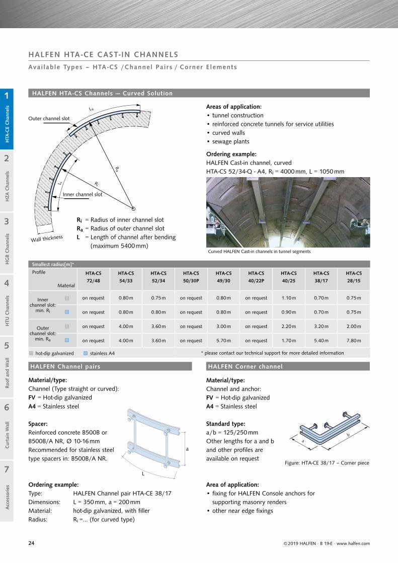
Smallest radius[m]*
Profile
Material
HTA-CS HTA-CS HTA-CS HTA-CS HTA-CS HTA-CS HTA-CS HTA-CS HTA-CS
72/48 54/33 52/34 50/30P 49/30 40/22P 40/25 38/17 28/15
Inner channel slot:
min. Ri
on request 0.80 m 0.75 m on request 0.80 m on request 1.10 m 0.70 m 0.75 m
on request 0.80 m 0.80 m on request 0.80 m on request 0.90 m 0.70 m 0.75 m
Outer channel slot:
min. Ra
on request 4.00 m 3.60 m on request 3.00 m on request 2.20 m 3.20 m 2.00 m
on request 4.00 m 3.60 m on request 5.70 m on request 1.70 m 5.40 m 7.80 m
hot-dip galvanized stainless A4 * please contact our technical support for more detailed information
a
L
© 2019 HALFEN · B 19-E · www.halfen.com
Cur
tain
Wal
lH
TU C
hann
els
Roof
and
Wal
lH
TA-C
E C
hann
els
HG
B C
hann
els
1
2
5
4
3
7
6
HZA
Cha
nnel
sA
cces
sories
HALFEN HTA -CE CAST- IN CHANNELS
Avai lab le Types – HTA -CS /Channel Pa i r s / Corner E lements
Material/type:Channel (Type straight or curved):FV = Hot-dip galvanizedA4 = Stainless steel
Ordering example: Type: HALFEN Channel pair HTA-CE 38/17Dimensions: L = 350 mm, a = 200 mmMaterial: hot-dip galvanized, with fillerRadius: Ri =… (for curved type)
Standard type: a/b = 125/250 mmOther lengths for a and b and other profiles areavailable on request
Material/type:Channel and anchor: FV = Hot-dip galvanizedA4 = Stainless steel
Figure: HTA-CE 38/17 – Corner piece
Ri = Radius of inner channel slotRa = Radius of outer channel slotL = Length of channel after bending
(maximum 5400 mm)
Ordering example:HALFEN Cast-in channel, curvedHTA-CS 52/34-Q - A4, Ri = 4000 mm, L = 1050 mm
Area of application:• fixing for HALFEN Console anchors for
supporting masonry renders• other near edge fixings
Areas of application:• tunnel construction• reinforced concrete tunnels for service utilities• curved walls• sewage plants
HALFEN HTA-CS Channels — Curved Solution
Spacer: Reinforced concrete B500B orB500B/A NR, Ø 10-16 mmRecommended for stainless steel type spacers in: B500B/A NR.
Curved HALFEN Cast-in channels in tunnel segments
Outer channel slot
Inner channel slot
Wall thickness
HALFEN Corner channelHALFEN Channel pairs

2525
© 2019 HALFEN · B 19-E · www.halfen.com
Cur
tain
Wal
lH
TU C
hann
els
Roof
and
Wal
lH
TA-C
E C
hann
els
HG
B C
hann
els
1
2
5
4
3
7
6
HZA
Cha
nnel
sA
cces
sories
HALFEN HTA -CE CAST- IN CHANNELS
Calcu lat ion Bas ics
Verification method
9. Verify concrete failure for combined loading, (combination of 6. and 7. as well as combination of 6. and 8.).
8. Verify concrete edge failure (loading in shear) considering a possible structural edge reinforce-ment.
7. Verify pry-out failure (loading in shear).
6. Verify concrete cone failure (tension loading).
5. Verify anchor pull-out failure (tension loading).
4. Verify the connection between anchor and channel (tension loading).
2. Verify local load application (channel lips) for tension, shear and combined loading.
1. Select channel.
If verification is negative, determine required additional reinforcement.
If last verification is negative, determine required additional reinforcement.
General
Tip:A free, simple to use calculation software to simplify planning can be downloaded at www.halfen.com.
Engineering services and technical support for your individual projects.Our contact information can be found on page 91 of this catalogue.
Technical support
3. Calculate the anchor loads resulting from tensile loads and shear loads according to the load influence model (unfavour-able anchor and load position).
The following information is necessary to verify an anchor channel:
• type of HALFEN Cast-in channel and material
• length of the HALFEN Cast-in channel with number of anchors and spacing
• position of the HALFEN Cast-in channel in the concrete, defined by its distance from the lower, upper left and right edges of the component
• thickness of the concrete elements
• concrete strength class
• condition of the concrete; cracked or verified as non-cracked
• is there dense reinforcement in the vicinity of the anchor channel?
• HALFEN T-head bolt thread size
• bolt positions
• tensile load and shear load of each bolt
2626 © 2019 HALFEN · B 19-E · www.halfen.com
Cur
tain
Wal
lH
TU C
hann
els
Roof
and
Wal
lH
TA-C
E C
hann
els
HG
B C
hann
els
1
2
5
4
3
7
6
HZA
Cha
nnel
sA
cces
sories
HALFEN HTA -CE CAST- IN CHANNELS
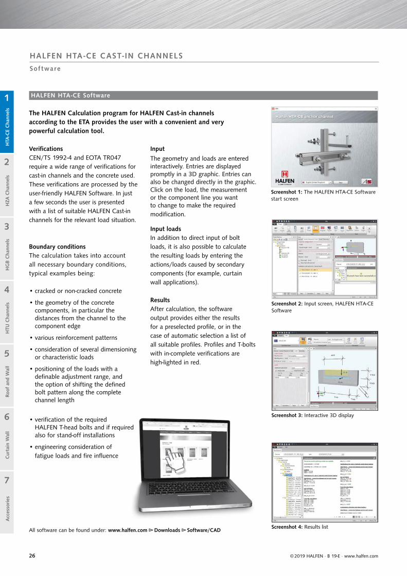
Sof tware
VerificationsCEN/TS 1992-4 and EOTA TR047 require a wide range of verifications for cast-in channels and the concrete used. These verifications are processed by the user-friendly HALFEN Software. In just a few seconds the user is presented with a list of suitable HALFEN Cast-in channels for the relevant load situation.
Boundary conditionsThe calculation takes into account all necessary boundary conditions, typical examples being:
• cracked or non-cracked concrete
• the geometry of the concrete components, in particular the distances from the channel to the component edge
• various reinforcement patterns
• consideration of several dimensioning or characteristic loads
• positioning of the loads with a definable adjustment range, andthe option of shifting the defined bolt pattern along the complete channel length
• verification of the required HALFEN T-head bolts and if required also for stand-off installations
• engineering consideration of fatigue loads and fire influence
HALFEN HTA-CE Software
Input
The geometry and loads are entered interactively. Entries are displayed promptly in a 3D graphic. Entries can also be changed directly in the graphic. Click on the load, the measurement or the component line you want to change to make the required modification.
Input loadsIn addition to direct input of bolt loads, it is also possible to calculate the resulting loads by entering the actions/loads caused by secondary components (for example, curtain wall applications).
ResultsAfter calculation, the softwareoutput provides either the results for a preselected profile, or in the case of automatic selection a list of all suitable profiles. Profiles and T-bolts with in-complete verifications are high-lighted in red.
The HALFEN Calculation program for HALFEN Cast-in channels according to the ETA provides the user with a convenient and verypowerful calculation tool.
All software can be found under: www.halfen.com ►► Downloads ►► Software/CAD
Screenshot 2: Input screen, HALFEN HTA-CE Software
Screenshot 1: The HALFEN HTA-CE Software start screen
Screenshot 4: Results list
Screenshot 3: Interactive 3D display

2727
ETA - 09 / 0339
© 2019 HALFEN · B 19-E · www.halfen.com
Cur
tain
Wal
lH
TU C
hann
els
Roof
and
Wal
lH
TA-C
E C
hann
els
HG
B C
hann
els
1
2
5
4
3
7
6
HZA
Cha
nnel
sA
cces
sories
HALFEN HTA -CE CAST- IN CHANNELS
Sof tware
HALFEN HTA-CE Software
Visual controlAll verifications for the current channel profile are listed in a tree structure. Green check-marks indicate successful verifications. Red check-marks indicate unsatisfactory verifications.
For further visual control a progressbar on the right indicates the status of the verification process. Here too, red bars mean that a load has been exceeded, while green bars symbolize verifica-tions that meet the criteria.
Detailed calculation information (with load positions, section sizes and utilization factors) can also be selected in a tree menu.
After selecting a HALFEN Cast-in channel and suitable bolts, the dimensioning results can be imported into the data list and saved.
Print-outsPrint-outs are possible in a brief and in a verifiable long version. The long ver-sion includes all decisive verifications, a diagram of necessary reinforcement and a 2D graphic of the geometry and load.
The latest version of the dimensioning program is available for download on the Internet at www.halfen.com.
System requirements:
• Windows 10, Windows 8, Windows 7,
• Microsoft .NET Framework 4.6
Screenshot 5: Overview of results
Screenshot 6: Print preview
HALFEN HTA-CE type Channel 49/30 - A4 - 350 - KF - ANK.A
HALFEN HTA-CE Channel 49/30 with smooth channel lips for adjustable fixing of components,
according to European Technical approval ETA-09/0339, suitable for anchoring in reinforced or non-reinforced standard concrete in a strength class of at least C12/15 and a maximum C90/105 in accordance with EN 206 under quasi-static loading as well as fire exposure.
Type HTA-CE 49/30 - A4 - 350 - KF - ANK.A4withNRk,s,c = 31 kN = char. resistance, steel failure (tension), connection channel anchorA4 = Carbon steel or stainless steel 1.4404 / 1.4571,350 = Channel length [mm] with 3 anchors,KF = Foam strip filler, ANK.A4 = Anchor in stainless steel 1.4404 / 1.4571 / 1.4578,
or equivalent; deliver and install according to the manufacturer’s instructions.
Tender text

28
z
xy
z
xy
© 2019 HALFEN · B 19-E · www.halfen.com
Cur
tain
Wal
lH
TU C
hann
els
Roof
and
Wal
lH
TA-C
E C
hann
els
HG
B C
hann
els
1
2
5
4
3
7
6
HZA
Cha
nnel
sA
cces
sories
offi
cially
approvedApp. No Z - 21.4 - 1691
Apart from excellent adjustability, HALFEN Cast-in channels save
considerable installation time. The result: faster construction and therefore reduced overall costs.
Quick and economical
• adjustable anchorage
• bolts instead of welding
• maximum efficiency when installing in rows
• cost-effective installation using standard tools
• optimized pre-planning reduces construction time
• large range of channels types for various applications
• user-friendly installation; no noise, dust and vibration
Safe and reliable
• no damage to the mainreinforcement
• approved for fire-resistantstructural elements
• suitable for installation in concrete pressure and concrete tensile zones
• hot-rolled channels, suitable for dynamic loads
• building authority approved
HALFEN HZA Cast-in channelsThe advantages at a glance
HZA HALFEN ChannelsCold-rolled, serrated
serrated
serrated
serrated
suitable for dynamic loads
suitable for dynamic loads
3D -Loads
3D -Loads
3D - Loads
HZA HALFEN DYNAGRIP ChannelsHot-rolled, serrated
HZA-PS HALFEN Channels Hot-rolled, serrated
Z-21.4-145
Z-21.4-1691
z
xy
suitable for seismic loading
HALFEN HZA-PS Cast-in channels More Information on the HZA-PS is available at: www.halfen.com ►► Products ►► Fixing systems ►► HZA - DYNAGRIP Cast-In Channels
Or scan the QR-Code and select the current “HZA-PS“ catalogue.
offi
cially
approv
ed
App. No Z - 21.4 - 145
suitable for applications in safety relevant areas in nuclear facilities

29© 2019 HALFEN · B 19-E · www.halfen.com
Cur
tain
Wal
lH
TU C
hann
els
Roof
and
Wal
lH
TA-C
E C
hann
els
HG
B C
hann
els
1
2
5
4
3
7
6
HZA
Cha
nnel
sA
cces
sories
HALFEN HZA CAST- IN CHANNELS
Appl i c a t ion Examples : Ins ta l la t ions wi th HALFEN Ca s t - in Channe ls HZA
Fixings of a Curtain wall façade, HZA near edge installation
LIFTS / ELEVATORS
Fixing for guide-rails Vertical channels in columns to attach further components
Fixings for emergency access balconies(Vertical installation of HALFEN Channels)
INDUSTRIAL PLANT INSTALLATIONS
Pipe supports on vertical HZA Channels Fixings of the drive unit for a ski lift
CURTAIN WALL FAÇADES
SKI LIFT
INDUSTRIAL BUILDING

30
Available HZA
Profile HZA 64/44 DYNAGRIP
HZA 53/34DYNAGRIP
HZA 38/23DYNAGRIP
HZA 29/20DYNAGRIP
HZA 41/22
GeometryHALFEN HZA Channels
hot-rolled cold-rolled
FRd37.8 kN
all load directions
26.6 kN 30.8 kN 16.8 kNall load directions
11.2 kNall load directions
7.0 kNall load directionsall load directions
Material
Bolt HZS 64/44 HZS 53/34 HZS 38/23 HZS 29/20 HZS 41/22
Material and area of application
Area of application
Use only possible if all fixture components are protected by a minimum concrete cover, depending on environmental conditions, as specified in DIN EN 1992-1-1:2011-01.
For interior use only, for example; in residential, office and school buildings, hospital and retail facilities, not suitable for wet rooms.
For use in building compo-nents in rooms with normal humidity (including kitchens, bathrooms, laundry rooms in residential buildings).
Building components, corrosion class III, according to EN 1993-1-4, table A.3.
Channel profile Mill finish Hot-dip galvanized(thickness ≥ 50 μm)
Hot-dip galvanized(thickness ≥ 50 μm)
Stainless steel1.4404/1.4571
Anchor Mill finish Hot-dip galvanized(thickness ≥ 50 μm)
Hot-dip galvanized(thickness ≥ 50 μm)
Welded anchor mill finish
Bolt anchor instainless steel
1.4404/1.4571
Stainless steel1.4404/1.44621.4571/1.4578
Bolts, nuts, washers No corrosion protection
Zinc galvanized(thickness ≥ 5 μm)
Mechanically galvanized(thickness ≥ 10 μm)
Hot-dip galvanized (thickness ≥ 40 μm)
Stainless steelA4-50FA-70A4-70
Or zinc galvanized with special coating, thickness > 12 μm. Only allowed for profiles 38/23, 53/34, 64/44 and 41/22.
For corrosion protection of the welded anchors a minimum concrete cover c is given:for profile (38/23) 30 mm; (41/22) 30 mm; (53/34) 40 mm; (64/44) 50 mm.
3416
5
22.5
52.5
20.7
41.3
22.3
85
2399
18
38
8720
29
1414
44
187
26
64
h ins
t
d
bch
h ch
© 2019 HALFEN · B 19-E · www.halfen.com
Cur
tain
Wal
lH
TU C
hann
els
Roof
and
Wal
lH
TA-C
E C
hann
els
HG
B C
hann
els
1
2
5
4
3
7
6
HZA
Cha
nnel
sA
cces
sories
HALFEN HZA CAST- IN CHANNELS
Area s o f Appl i c a t ion / Produc t Range
A4 = Stainless steel1.4571/1.4404
Suitable for dynamic loads FV = Steel hot-dip galvanized1.0038/1.0044
Note: observe the installation height hinst
Nominal size and tolerance
31
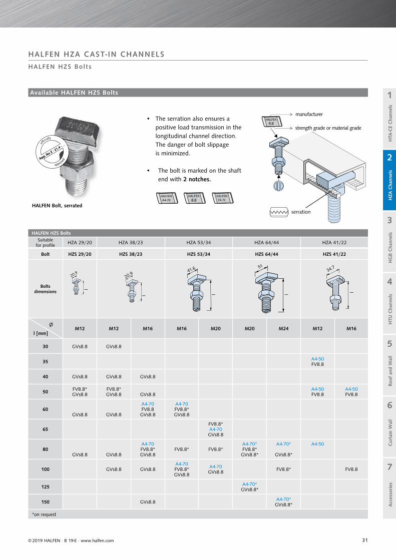
HALFEN HZS BoltsSuitable
for profile HZA 29/20 HZA 38/23 HZA 53/34 HZA 64/44 HZA 41/22
Bolt HZS 29/20 HZS 38/23 HZS 53/34 HZS 64/44 HZS 41/22
Bolts dimensions
∅ l [mm]
M12 M12 M16 M16 M20 M20 M24 M12 M16
30 GVs8.8 GVs8.8
35 A4-50FV8.8
40 GVs8.8 GVs8.8 GVs8.8
50 FV8.8* GVs8.8
FV8.8*GVs8.8 GVs8.8
A4-50FV8.8
A4-50FV8.8
60GVs8.8 GVs8.8
A4-70FV8.8 GVs8.8
A4-70FV8.8*GVs8.8
65FV8.8*A4-70GVs8.8
80GVs8.8 GVs8.8
A4-70FV8.8*GVs8.8
FV8.8* FV8.8*A4-70* FV8.8* GVs8.8*
A4-70*
GVs8.8*
A4-50
100 GVs8.8 GVs8.8A4-70FV8.8*GVs8.8
A4-70GVs8.8 FV8.8* FV8.8
125 A4-70*GVs8.8*
150 GVs8.8 A4-70*GVs8.8*
*on request
HALFENA4-70
HALFENA4-70
HALFEN8.8
HALFEN8.8
HALFENFA 70
HALFENFA 70
28.820.941,6 41,651
© 2019 HALFEN · B 19-E · www.halfen.com
Cur
tain
Wal
lH
TU C
hann
els
Roof
and
Wal
lH
TA-C
E C
hann
els
HG
B C
hann
els
1
2
5
4
3
7
6
HZA
Cha
nnel
sA
cces
sories
App. No Z - 21.4 - . .
.
o
fficially
approv
ed
HALFEN HZA CAST- IN CHANNELS
HALFEN HZS Bol ts
HALFEN Bolt, serratedserration
• The serration also ensures a positive load transmission in the longitudinal channel direction. The danger of bolt slippage is minimized.
• The bolt is marked on the shaft end with 2 notches.
Available HALFEN HZS Bolts
manufacturer
strength grade or material grade
HALFEN8.8
HALFEN8.8
41.6
20.9
l
l l l l
34.7

32
Standard lengths — Project related orders
HZA 38/23, 41/22, 53/34, 64/44
Length [mm] / Number of anchors
1050 / 5 1300 / 6 1550 / 7 1800 / 8
2050 / 9 2300 / 10 2550 / 11 2800 / 12
3030 / 13 3300 / 14 3550 / 15 3800 / 16
4050 / 17 4300 / 18 4550 / 19 4800 / 20
5050 / 21 5300 / 22 5550 / 23 5800 / 24
Standard lengths — Project related orders
HZA 29/20
Length [mm] / Number of anchors
1250 / 7 1450 / 8 1650 / 9 1850 / 10
2050 / 11 2250 / 12 2450 / 13 2650 / 14
2850 / 15 3030 / 16 3250 / 17 3450 / 18
3650 / 19 3850 / 20 4050 / 21 4250 / 22
4450 / 23 4650 / 24 4850 / 25 5050 / 26
5250 / 27 5450 / 28 5650 / 29 5850 / 30
200
200×
200 200 20025 25
See HALFEN Price list for standard product range (short channels etc.)
HALFEN HZA Channels — Standard lengths and Anchor positions
Smallest radius [m]*
Profile
Material
HZA-CS HZA-CS HZA-CS HZA-CS HZA-CS
64/44 53/34 38/23 29/20 41/22
Inner channel slot:
min. Ri
on request on request 2.60 m 0.85 m 0.70 m
on request on request 1.20 m - 0.70 m
Outer channel slot:
min. Ra
on request on request 1.40 m 1.10 m 2.20 m
on request on request 3.50 m - 4.80 m
hot-dip galvanized A4 stainless steel * please contact our technical support for more detailed information
Cur
tain
Wal
lH
TU C
hann
els
Roof
and
Wal
lH
TA-C
E C
hann
els
HG
B C
hann
els
1
2
5
4
3
7
6
HZA
Cha
nnel
sA
cces
sories
© 2019 HALFEN · B 19-E · www.halfen.com
HALFEN HZA CAST- IN CHANNELS
HALFEN HZA Channels : S tandard Lengths/ HALFEN HZA Channels cur ved so lut ion
HALFEN HZA Channels curved solution
Ri = Radius of inner channel slotRa = Radius of outer channel slotL = Length of channel after bending
(maximum 5400 mm)
Ordering example:HALFEN Cast-in channel, curvedHZA-CS 38/23-Q - A4, Ri = 4000 mm, L = 1050 mm
Curved HALFEN Cast-in channels in tunnel segments
Outer channel slot
Inner channel slot
Wall thickness
Areas of application:• tunnel construction• reinforced concrete tunnels for utilities• curved walls• sewage plants
33
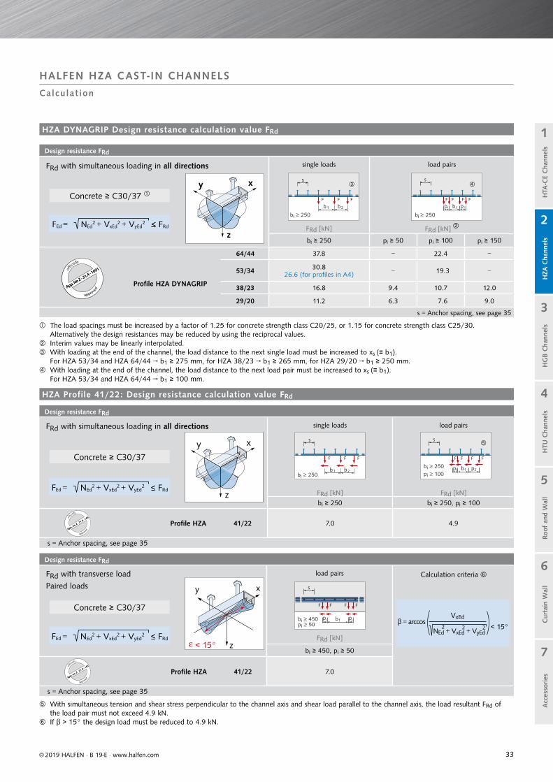
Design resistance FRd
load pairs
FRd [kN]
bi ≥ 450, pi ≥ 50
Profile HZA 41/22 7.0
s = Anchor spacing, see page 35
Design resistance FRd
single loads load pairs
FRd [kN] FRd [kN]
bi ≥ 250 pi ≥ 50 pi ≥ 100 pi ≥ 150
64/44 37.8 − 22.4 −
Profile HZA DYNAGRIP
53/34 30.826.6 (for profiles in A4) − 19.3 −
38/23 16.8 9.4 10.7 12.0
29/20 11.2 6.3 7.6 9.0
s = Anchor spacing, see page 35
Design resistance FRd
single loads load pairs
FRd [kN] FRd [kN]
bi ≥ 250 bi ≥ 250, pi ≥ 100
Profile HZA 41/22 7.0 4.9
s = Anchor spacing, see page 35
HZA Profile 41/22: Design resistance calculation value FRd
xy
z< 15°ε
b1b 450≥i≥pi 50
p1 p2
s
F F F F
b b1 2b 250≥i
s
F F F
s
b1b 250≥i
≥pi 100pp 21
F F F F
b b1 2
b 250≥i
s
F F F
s
b1
b 250≤i
p p21
F F F F
z
xy
z
xy
Cur
tain
Wal
lH
TU C
hann
els
Roof
and
Wal
lH
TA-C
E C
hann
els
HG
B C
hann
els
1
2
5
4
3
7
6
HZA
Cha
nnel
sA
cces
sories
© 2019 HALFEN · B 19-E · www.halfen.com
Calcu lat ion
HALFEN HZA CAST- IN CHANNELS
offi
cially
approv
ed
App. no. Z - 21.4 - 145
offi
cially
approv
ed
App. no. Z - 21.4 - 145
offi
cially
approvedApp. No Z - 21.4 - 1691
The load spacings must be increased by a factor of 1.25 for concrete strength class C20/25, or 1.15 for concrete strength class C25/30. Alternatively the design resistances may be reduced by using the reciprocal values.
Interim values may be linearly interpolated. With loading at the end of the channel, the load distance to the next single load must be increased to xs (≡ b1).
For HZA 53/34 and HZA 64/44 → b1 ≥ 275 mm, for HZA 38/23 → b1 ≥ 265 mm, for HZA 29/20 → b1 ≥ 250 mm. With loading at the end of the channel, the load distance to the next load pair must be increased to xs (≡ b1).
For HZA 53/34 and HZA 64/44 → b1 ≥ 100 mm.
With simultaneous tension and shear stress perpendicular to the channel axis and shear load parallel to the channel axis, the load resultant FRd of the load pair must not exceed 4.9 kN.
If > 15° the design load must be reduced to 4.9 kN.
FRd with simultaneous loading in all directions
NEd2 + VxEd
2 + VyEd2 < FRdFEd =
Concrete ≥ C30/37
NEd2 + VxEd
2 + VyEd2 < FRdFEd =
Concrete ≥ C30/37
Concrete ≥ C30/37
FRd with simultaneous loading in all directions
FRd with transverse load
Paired loads
NEd2 + VxEd
2 + VyEd2 < FRdFEd =
Calculation criteria
β = arccosVxEd
< 15°NEd + VxEd + VyEd2 2 2
HZA DYNAGRIP Design resistance calculation value FRd
34
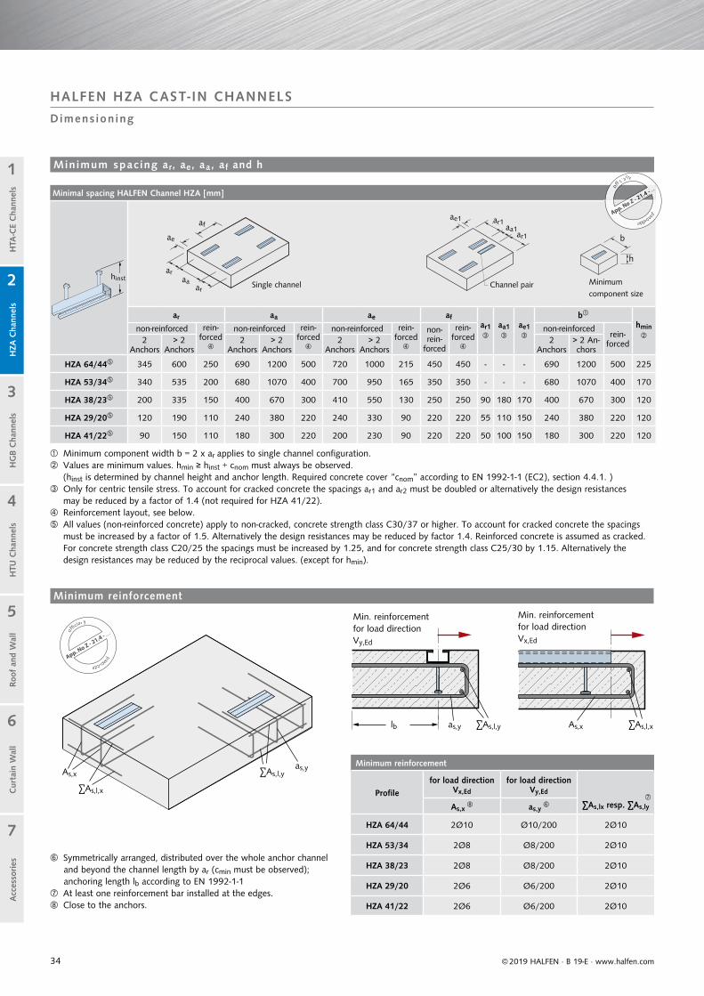
Minimal spacing HALFEN Channel HZA [mm]
ar aa ae afar1
aa1
ae1
bhmin
non-reinforced rein-forced
non-reinforced rein-forced
non-reinforced rein-forced
non-rein-
forced
rein-forced
non-reinforcedrein-
forced2 Anchors
> 2 Anchors
2 Anchors
> 2 Anchors
2 Anchors
> 2 Anchors
2 Anchors
> 2 An-chors
HZA 64/44 345 600 250 690 1200 500 720 1000 215 450 450 - - - 690 1200 500 225
HZA 53/34 340 535 200 680 1070 400 700 950 165 350 350 - - - 680 1070 400 170
HZA 38/23 200 335 150 400 670 300 410 550 130 250 250 90 180 170 400 670 300 120
HZA 29/20 120 190 110 240 380 220 240 330 90 220 220 55 110 150 240 380 220 120
HZA 41/22 90 150 110 180 300 220 200 230 90 220 220 50 100 150 180 300 220 120
Minimum component width b = 2 x ar applies to single channel configuration. Values are minimum values. hmin ≥ hinst + cnom must always be observed.
(hinst is determined by channel height and anchor length. Required concrete cover “cnom” according to EN 1992-1-1 (EC2), section 4.4.1. ) Only for centric tensile stress. To account for cracked concrete the spacings ar1 and ar2 must be doubled or alternatively the design resistances may be reduced by a factor of 1.4 (not required for HZA 41/22). Reinforcement layout, see below. All values (non-reinforced concrete) apply to non-cracked, concrete strength class C30/37 or higher. To account for cracked concrete the spacings
must be increased by a factor of 1.5. Alternatively the design resistances may be reduced by factor 1.4. Reinforced concrete is assumed as cracked. For concrete strength class C20/25 the spacings must be increased by 1.25, and for concrete strength class C25/30 by 1.15. Alternatively the design resistances may be reduced by the reciprocal values. (except for hmin).
Minimum reinforcement
Profilefor load direction
Vx,Ed
for load direction Vy,Ed
∑As,lx resp. ∑As,lyAs,x as,y
HZA 64/44 2Ø10 Ø10/200 2Ø10
HZA 53/34 2Ø8 Ø8/200 2Ø10
HZA 38/23 2Ø8 Ø8/200 2Ø10
HZA 29/20 2Ø6 Ø6/200 2Ø10
HZA 41/22 2Ø6 Ø6/200 2Ø10
b
h
as,y
as,y
lb As,x
As,x
∑As,l,y
∑As,l,y
∑As,l,x
∑As,l,x
af
ae
araa
ar
ae1 ar1
ar1aa1
Cur
tain
Wal
lH
TU C
hann
els
Roof
and
Wal
lH
TA-C
E C
hann
els
HG
B C
hann
els
1
2
5
4
3
7
6
HZA
Cha
nnel
sA
cces
sories
© 2019 HALFEN · B 19-E · www.halfen.com
HALFEN HZA CAST- IN CHANNELS
Dimens ioning
Z - 21.4 -
App. No Z ZZ -
.. . .ooffifficially
approrr voo
ev
dApp. No Z - 2
1.4 - . ..offi
cially
approrr voo
ev
d
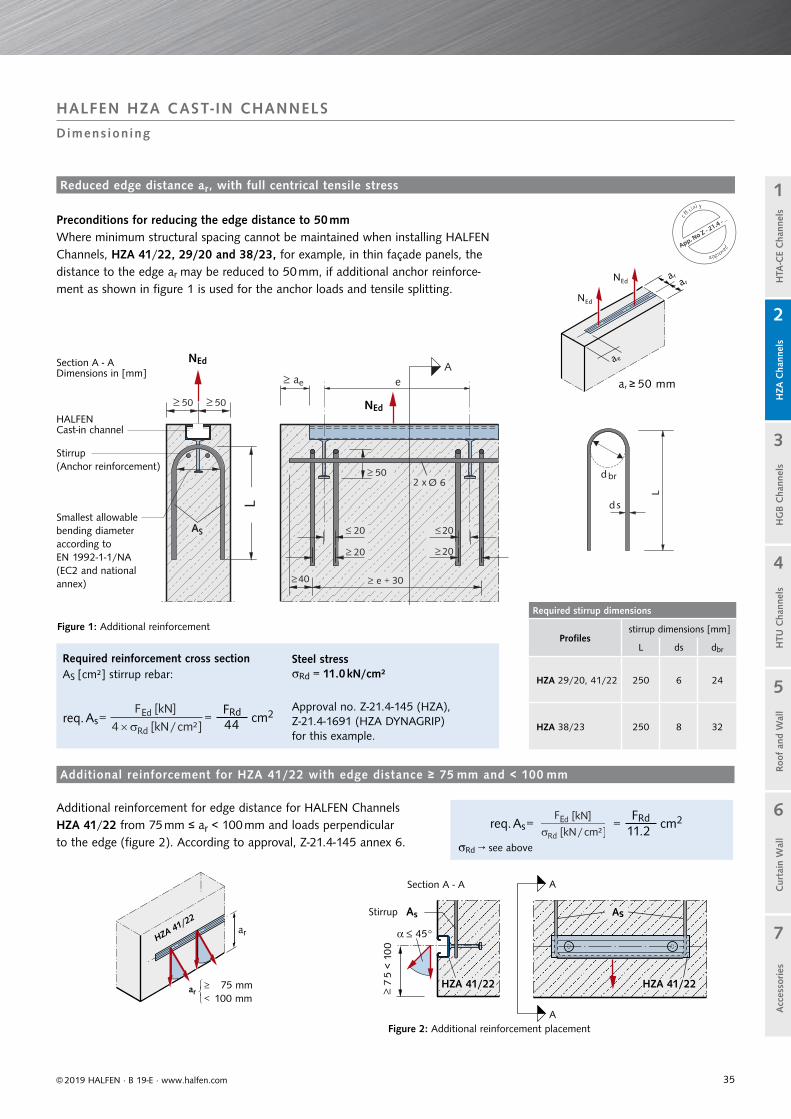
Minimum spacing ar, ae, aa, af and h
Minimum reinforcement
Symmetrically arranged, distributed over the whole anchor channel and beyond the channel length by ar (cmin must be observed); anchoring length lb according to EN 1992-1-1
At least one reinforcement bar installed at the edges. Close to the anchors.
Min. reinforcement for load direction Vy,Ed
Single channel Minimum component size
Channel pairhinst
Min. reinforcement for load direction Vx,Ed
35
Required stirrup dimensions
Profilesstirrup dimensions [mm]
L ds dbr
HZA 29/20, 41/22 250 6 24
HZA 38/23 250 8 32
20
20
20
20
50
40 30
50 50
L
L
d s
dbr
ae
ar ≥ 50 mm
NEd
NEd
a ra r
75 mm100 mm
HZA 41/22HZA 41/22
As
© 2019 HALFEN · B 19-E · www.halfen.com
Cur
tain
Wal
lH
TU C
hann
els
Roof
and
Wal
lH
TA-C
E C
hann
els
HG
B C
hann
els
1
2
5
4
3
7
6
HZA
Cha
nnel
sA
cces
sories
App. No Z - 21.4 - . .
.officially
approrr voo
ev
d
NEd
NEd
Reduced edge distance ar, with full centrical tensile stress
Preconditions for reducing the edge distance to 50 mmWhere minimum structural spacing cannot be maintained when installing HALFEN Channels, HZA 41/22, 29/20 and 38/23, for example, in thin façade panels, the distance to the edge ar may be reduced to 50 mm, if additional anchor reinforce-ment as shown in figure 1 is used for the anchor loads and tensile splitting.
HALFEN Cast-in channel
Stirrup(Anchor reinforcement)
Smallest allowablebending diameter according to EN 1992-1-1/NA (EC2 and national annex)
Additional reinforcement for HZA 41/22 with edge distance ≥ 75 mm and < 100 mm
Figure 2: Additional reinforcement placement
Section A - A
Additional reinforcement for edge distance for HALFEN Channels HZA 41/22 from 75 mm ≤ ar < 100 mm and loads perpendicular to the edge (figure 2). According to approval, Z-21.4-145 annex 6.
HALFEN HZA CAST- IN CHANNELS
Dimens ioning
Rd → see above
E
Section A - ADimensions in [mm]
Figure 1: Additional reinforcement
Stirrup
req. As =
As
Steel stressRd = 11.0 kN/cm²
Approval no. Z-21.4-145 (HZA),Z-21.4-1691 (HZA DYNAGRIP)for this example.
E
Required reinforcement cross sectionAS [cm²] stirrup rebar:
req. As =FRd= cm244
FRd= cm211.2

36
Bolts type HZS — Design values FRd and MRd
Grade 8.8 Stainless steel A4-50, HCR-50 Stainless steel A4-70
Bending moment for each bolt
Bending moment for each bolt
Bending moment for each bolt
Bolt type FRd [kN] MRd [Nm] FRd [kN] MRd [Nm] FRd [kN] MRd [Nm]
29/20 - M 12 27.0 83.8 – – – –
38/23 - M 12 27.0 83.8 – – – –
38/23 - M 16 50.2 213.1 – – 42.2 149.4
41/22 - M 12 27.0 83.8 10.6 27.5 – –
41/22 - M 16 50.2 213.1 19.8 70.0 – –
53/34 - M 16 50.2 213.1 – – 42.2 149.4
53/34 - M 20 78.4 415.4 – – 66.0 291.3
64/44 - M 20 78.4 415.4 – – 66.0 291.3
64/44 - M 24 113.0 718.4 – – 95.1 503.7
Cur
tain
Wal
lH
TU C
hann
els
Roof
and
Wal
lH
TA-C
E C
hann
els
HG
B C
hann
els
1
2
5
4
3
7
6
HZA
Cha
nnel
sA
cces
sories
© 2019 HALFEN · B 19-E · www.halfen.com
HALFEN HZA CAST- IN CHANNELS
HALFEN Bol ts : Dimens ioning / HALFEN HZA Channels : S tandard Lengths
HALFEN HZS Bolts — Load capacity and bending moment
Observe profile load bearing capacity! If the load bearing capacity of the bolt and the HALFEN Cast-in channel differ; use the smaller of both values.
Bending moment in the profile or concrete edge; see note below if bending with additional centric or diagonal tensile stress occurs.
Variable bending stress: For façades renders subjected to variable stress conditions (e.g. due to temperature change), the alternating stress amplitude must not exceed a value of σA = ± 50 N/mm2 (=1.0) with a mean value of σM (relative to the stressed cross section of the bolt).
Note: Combine stress values if bending occurs with additional centric or diagonal tensile stress.
NEd ≤ FRd × (1 − MEd / MRd)
FRd = Bolt design load capacity
MRd = Design value of possible bending moment
NEd = Design value of actual tensile load
MEd = Design value of actual bending moment
Torque values [Nm]
Bolt typeMaterial / Grade HZS 64/44
8.8HZS 64/44
A4-70HZS 53/34
8.8HZS 53/34
A4-70HZS 41/22
8.8HZS 41/22
A4-50HZS 38/23
8.8HZS 38/23
A4-70HZS 29/20
8.8Thread
M12 ‒ ‒ ‒ ‒ 50 50 80 ‒ 80
M16 ‒ ‒ 200 200 120 80 120 120 ‒
M20 350 350 350 350 ‒ ‒ ‒ ‒ ‒
M24 450 450 ‒ ‒ ‒ ‒ ‒ ‒ ‒
Torque values apply only for bolts in delivery condition (unlubricated).
Torque values for HALFEN Bolts

37
Allowable stress amplitude for load cycle n = 2 × 10 6
Profile, anchor configuration
Material
Allow. stress amplitudeΔF = Fo − Fu [kN] for tensile stress
Approvedbolts
29/20-B6, 29/20-Q 1.0044 2.0 M12
38/23-B6, 38/23-Q
1.0044 3.0
M161.4404/1.4571 2.4
53/34-B6, 53/34-Q
1.0044 6.0 / (12 )
M16, 201.4404/1.4571 4.0 / (10 )
64/44-Q/L1.0044 15.0
M20, 241.4404/1.4571 11.0
Design resistance for n = 2 × 10 6 load cycles
Profile HTA
Type ΔNRd,s,0,nAllowable
bolts Material
40/22P FV 2.94M12
M16
8.8
4.6 / 8.8
50/30P FV 3.6M16
M20
4.6 / 8.8
4.6 / 8.8
52/34 FV 4.9M16
M20
8.8
8.8
0
5
10
15
20
25
35
5 10 15 20 25
45°
30.6
30.6
4.9
NRd
NEd
16,8 kN
13,8 kN
Lastspielzahl N
1 Lastspiel
No = Oberlast
Nu = Unterlast
Cur
tain
Wal
lH
TU C
hann
els
Roof
and
Wal
lH
TA-C
E C
hann
els
HG
B C
hann
els
1
2
5
4
3
7
6
HZA
Cha
nnel
sA
cces
sories
© 2019 HALFEN · B 19-E · www.halfen.com
HALFEN CAST- IN CHANNELS HZA AND HTA
Dynamic Loading
lowest load
1 load cycle
Number of load cycles N
highest load16.8 kN
Anchor configuration:B6: with bolt anchorQ: with I - anchor welded transverse to the channel
Also see approval Z-21.4-1691
values apply for anchor channels with weld-on anchors type I 140/7.1 with anchor orientation Q (crosswise), weld joint position L (lengthwise)
Example:HZA 38/23 profile - FV (standard, hot-dip galvanized), channel length = 250 mm
max. load: FRd = N0 = 16.8 kN
of which dynamic load: 3 kN (stress amplitude Δ F)
Load F
Example (also see diagram to the right):Profile HTA-CE 52/34 - FV (standard, hot-dip galvanized), for n = 2 × 10⁶ load cycles:
NRd = 55 ÷ 1.8 = 30.6 (taken from the ETA)
NEd from permanent load = 10 kN (assumption)
Δ NRd,E,n = (30.6 − 10) × 4.9/30.6 = 3.3 kN
The stress amplitudes shown here only apply to anchor channels made of the specified material and with the specified anchor types.
Only the corresponding bolts according to the tables on this page are allowed.
Allowable amplitude / HALFEN HZA Channels, serrated
Design resistance / HALFEN HTA Channels
Dynamic loads for hot-rolled HALFEN Cast-in channels
NEd = 10 kN
Δ NRd,E,n = 3.3 kN
Δ N
Rd,
s,0,
n
NEd = 10 kN
Diagram: HTA-CE 52/34 - FV for n = 2 × 10⁶ load cycles

38 © 2019 HALFEN · B 19-E · www.halfen.com
Cur
tain
Wal
lH
TU C
hann
els
Roo
f an
d W
all
HG
B C
hann
els
1
2
5
4
3
7
6
Acc
esso
ries
H
ZA C
hann
els
HTA
-CE
Cha
nnel
sC
urta
in W
all
HTU
Cha
nnel
sRoo
f an
d W
all
HG
B C
hann
els
1
2
5
4
3
7
6
Acc
esso
ries
H
ZA C
hann
els
HTA
-CE
Cha
nnel
s
C onstruction specialists consider the HALFEN HGB Handrail
connections to be particularly suited for fastening banisters to the thin front faces of balcony slabs.
Fast and cost-effective
• adjustable anchorage
• can also be used in slabs as thin ash ≥ 100 mm
• installed with bolts instead of welding or drilling
• pre-planning reduceson-site construction time
• all attached components remain fully adjustable or are easily replaced as required
Safe and reliable
• statically verified installation• no damage to visible surfaces of
concrete slabs• also suitable to secure mandatory
safety rails during construction (Refer to: EN 795 "Guard rails")
• use with HALFEN high-strengthbolts to ensure a secure and statically sound connection of banister/railing components
HALFEN HGB Handrail connections
Profi le HGB E-54/33-A4
HALFEN HGB Handrail connections
Profi le HGB E-49/30-A4
HALFEN HGB Handrail connections
Profi le HGB E-40/25-A4
HALFEN HGB Handrail connections
Profi le HGB E-38/17-A4
HGB Handrail ConnectionsThe advantages at a glance
App. No Z - 21.4 - 1912
o
fficially
approv
ed
Z-21.4-1912

39© 2019 HALFEN · B 19-E · www.halfen.com
Cur
tain
Wal
lH
TU C
hann
els
Roo
f an
d W
all
HG
B C
hann
els
1
2
5
4
3
7
6
Acc
esso
ries
H
ZA C
hann
els
HTA
-CE
Cha
nnel
s
HALFEN HGB HANDRAIL CONNECTIONS
Appl icat ion Examples
Used to secure safety rails during the construction phase Cast-in HGB Channel, residential building
Fixing of safety rails, Rheinenergiestadion Cologne Fixing of safety rails, Rheinenergiestadion Cologne
–: Safety barrier installation, multi purpose arena in Berlin
SAFETY BARRIERS IN STADIUMS
RAILINGS
40 © 2019 HALFEN · B 19-E · www.halfen.com
Cur
tain
Wal
lH
TU C
hann
els
Roo
f an
d W
all
HG
B C
hann
els
1
2
5
4
3
7
6
Acc
esso
ries
H
ZA C
hann
els
HTA
-CE
Cha
nnel
sC
urta
in W
all
HTU
Cha
nnel
sRoo
f an
d W
all
HG
B C
hann
els
1
2
5
4
3
7
6
Acc
esso
ries
H
ZA C
hann
els
HTA
-CE
Cha
nnel
s
HALFEN HGB HANDRAIL CONNECTIONS
Genera l
Balconies are part of the structural system. "They must be designed, constructed, maintained and modified in such a fashion that public order and safety, especially to health or life, is not endangered". Model building code and construction guidelines (Muster-bauordnung MBO 07 und Ausführungs-vorschriften).
Technical guidelines issued by public notice as technical building regulations must be observed.* Technical rules pro-vide information on load parameters, calculation, dimensioning of structural
Individual regional states have their own building codes and regulations. All current technical regulations require proof of structural safety and integrity. A static calcula-tion or a building authority certificate is required when designing and dimensioning the fixings for guard rails.
§ 4.2 (1) It is the contractor’s responsibility to provide the static documentation in ac-cordance with the contract. He has to observe the recognized standards of practice as well as with the provisions of the law and regulatory directives. Tender and Contract Regulations for the German building industry (VOB Vergabe- und Vertragsordnung für Bauleistungen) Part B, § 4.3, requires the contractor to report to the customer, in writ-ing, any obvious design flaws, which he as the expert must be able to recognize. He alone is responsible for any resulting defect and consequential expenses. If he has sat-isfied his reporting obligation, the responsibility for the defect passes to the customer (defect example: banister attachment mounted in too thin a concrete slab).
products, construction types, structural layouts etc. A requirement of regional building codes refers to structural sta-bility: "All structures must, as a whole and in its individual components, be structurally self-supporting". This stabil-ity must be statically verifiable based on current technical standards.
A further building regulation addresses traffic loads, for example: Balconies and loggias must be fitted with safety rails to prevent falls when they border on to an area with a drop of more than one metre. For a drop height up
Regulations, standards and directives (to be observed when designing safety rails)
to 12 m the minimum banister height is 0.90 m measured from the upper surface of the finished floor surface or accessible ledge. For drop heights greater than 12 m the banister height must be at least 1.10 m. For exceptions see the German Federal building regu-lations / Deutsche LandesBauOrdnung.
Other regulations, not covered here, address the design, dimensioning, required spacings in the guard rail design, fire protection, thermal/sound insulation and rainwater drainage.
Regulatory requirements
Directive on metal banisters / balustrades, published by the; Federal Association of German Metalworkers (BVM Berufsverband Metall).
Regional Building Codes
VOB — Part B,§ 4, execution of
construction:
BVM Directive
Other applicable regulations and standards (Extract):
* issued by the highest construction supervision authorities of the German Federal States
• Accident Prevention Regulation “General Provisions” (VGB 1)• Industrial Safety Regulations• ETB — Directive “Fall Prevention Installations”, 1985 Issue• Stainless Steels, EC3 part 1–4
EN 1992-1-1 (EC2): Design and construction of concrete support structures; with National Annex (NA)
EN 1991 (EC1): General effects on load structures; with National Annex (NA)
EN 1993 (EC3): design and construction of steel structures; with National Annex (NA)

41
HALFEN Cast-in channels, stainless steel
Description Stainless steel
Materials StandardCorrosion resistance class
according to EN 1993-1-4, table A.3
Channel profile 1.4404 or 1.4571 EN 10 088 III
Ribbed-head anchor
Reinforcing steel B500BReinforcing steel BSt 500 NR DIN 488
HALFEN Bolts, stainless steel
Description Stainless steel
Materials StandardCorrosion resistance class
according to EN 1993-1-4, table A.3
Bolt A4-70:1.4404 or 1.4571
EN 3506-1 andEN 10 088 III
Hexagonal nut
A4-70:1.4404 or 1.4571
EN 3506-2 and EN 10 088 III
Washer 1.4404 or 1.4571 EN 10 088 III
HGB 49/30-A4
© 2019 HALFEN · B 19-E · www.halfen.com
Cur
tain
Wal
lH
TU C
hann
els
Roo
f an
d W
all
HG
B C
hann
els
1
2
5
4
3
7
6
Acc
esso
ries
H
ZA C
hann
els
HTA
-CE
Cha
nnel
s
HALFEN HGB HANDRAIL CONNECTIONS
Mater ia ls / Corros ion Protect ion
A4 = Stainless steel
Galvanized:Dipped in a galvanizing bath at a temperature of approximately 460°C, a method used primarily for open-profile channels.
Stainless Steel A4:Chromium is the most important alloy element in
stainless steel. A specific chromium concentration
ensures the generation of a passive layer on the
surface of the steel that protects the base material
against corrosion. This explains the high corrosion
resistance of stainless steel.
Product identification• on channel side• additionally inside the profile
“Anchor channels in stainless steel may be used outdoors — also in an industrial and coastal environment, but may not be directly exposed to salt water”.See guidelines for “Metal banisters and balustrades” issued by the German Association of Metalworkers (BVM Bundesverband der Metallverarbeiter).
Stainless Steel
Galvanized material for interior, dry rooms, for instance
when installing staircase banisters in residential buildings,
schools or commercial retail stores.
Available on request
WB = Steel mill finish
Identification of HALFEN HGB Cast-in channels

42
Railing bolts
Stainless steel
Material grade A4-70 Torque [Nm]
HGB - M 50/30 M16 60
for profile 49/30 M12 25
and 54/33
HGB - M 40/22 M16 45
for profile 40/25 M12 25
HGB - M38/17 M16 40
for profile 38/17 M12 25
≥25
5≥2
≥45
≥45
≤100
≤100
l1
l 2
03
30
≥25≥25I
© 2019 HALFEN · B 19-E · www.halfen.com
Cur
tain
Wal
lH
TU C
hann
els
Roo
f an
d W
all
HG
B C
hann
els
1
2
5
4
3
7
6
Acc
esso
ries
H
ZA C
hann
els
HTA
-CE
Cha
nnel
s
HALFEN HGB HANDRAIL CONNECTIONS
Ins ta l la t ion / A ssembly
After striking the formwork remove the foam filler from the HALFEN Cast-in channels.
Where possible, use stainless steel nails to avoid corrosion.
Insert HGB-M Banister bolts into the HALFEN Cast-in channel (turn 90° until the bolt locks into place).
Tighten the nuts using a torque wrench. See table on the right for torque values
washers are ordered separately
Installation and adjustment of balustrades
Tighten the bolts
Nail the HALFEN Cast-in channel to the formwork
Short piece Corner piece(on request)
Dimensions [mm]:l1 = 170, l2 = 170, α = 90°
Nail the HALFEN Cast-in channel to the formwork
Fixing position of the bolts
1
2
3
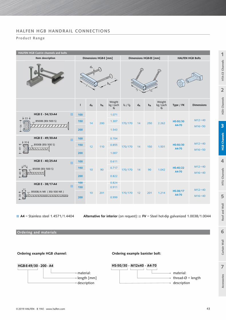
43
HALFEN HGB Cast-in channels and bolts
Item description Dimensions HGB-E [mm] Dimensions HGB-EE [mm] HALFEN HGB Bolts
l dA hA
Weightkg / each
Gl1 / l2 dA hA
Weightkg / each
GType / FK Dimensions
HGB E - 54/33-A4 100
14 200
1.071
170/170 14 250 2.262HS-50/30
A4-70
M12 × 40
M16 × 50
150 1.307
200 1.543
HGB E - 49/30-A4 100
12 110
0.704
170/170 14 150 1.501HS-50/30
A4-70
M12 × 40
M16 × 50
150 0.855
200 1.007
HGB E - 40/25-A4 100
10 90
0.611
170/170 14 90 1.042HS-40/22
A4-70
M12 × 40
M16 × 40
150 0.717
200 0.822
HGB E - 38/17-A4 100
10 201
0.824
170/170 12 201 1.214HS-38/17
A4-70
M12 × 40
M16 × 40
150 0.911
200 0.999
p
dA
hA
B500B (BSt 500 S)
B500B (BSt 500 S)
B500B (BSt 500 S)
B500B/A NR ( BSt 500 NR )
© 2019 HALFEN · B 19-E · www.halfen.com
Cur
tain
Wal
lH
TU C
hann
els
Roo
f an
d W
all
HG
B C
hann
els
1
2
5
4
3
7
6
Acc
esso
ries
H
ZA C
hann
els
HTA
-CE
Cha
nnel
sC
urta
in W
all
HTU
Cha
nnel
sRoo
f an
d W
all
HG
B C
hann
els
1
2
5
4
3
7
6
Acc
esso
ries
H
ZA C
hann
els
HTA
-CE
Cha
nnel
s
HALFEN HGB HANDRAIL CONNECTIONS
Product Range
A4 = Stainless steel 1.4571/1.4404 Alternative for interior (on request): FV = Steel hot-dip galvanized 1.0038/1.0044
Ordering example HGB channel:
HGB-E-49/30 - 200 - A4
material:length [mm]description
material:thread-Ø × lengthdescription
Ordering example banister bolt:
HS-50/30 - M12x40 - A4-70
Ordering and materials

44
h
b
OK FF
© 2019 HALFEN · B 19-E · www.halfen.com
Cur
tain
Wal
lH
TU C
hann
els
Roo
f an
d W
all
HG
B C
hann
els
1
2
5
4
3
7
6
Acc
esso
ries
H
ZA C
hann
els
HTA
-CE
Cha
nnel
sC
urta
in W
all
HTU
Cha
nnel
sRoo
f an
d W
all
HG
B C
hann
els
1
2
5
4
3
7
6
Acc
esso
ries
H
ZA C
hann
els
HTA
-CE
Cha
nnel
s
HALFEN HGB HANDRAIL CONNECTIONS
Dimens ioning Fundamenta ls
The minimum height hb of a banister is 0.90 m from the top surface of the finished floor or accessible ledge to the upper edge of the rail. For drop heights of more than 12.0 m the banister must be at least 1.10 min height. (Exceptions; as specified in regional building codes)
It would be advisable to have one uniform minimum height of 1.00 m as has already been mandated in the commercial sector and in a number of European countries.
Anchor channels or dowel installations require concrete of at least C 20/25 grade. If the concrete grade is less than C 20/25 grade or it is unknown a case-by-case decision must be made.
The thickness of the balcony slab must be at least h = 100 – 150 mm when the HGB is mounted in the slab edge (depends on channel profile and according to the German HGB approval). Other types of installation and systems require a thicker slab. All weather-exposed concrete-embedded installations (e.g. for balconies) must be made of stainless steel.
Any structural design must take all basic requirements for railings and banisters into account. As a general rule, all railings and banisters must be designed so that personal injury is ruled out, for instance with correct spacing of rails, lattice bars or panels. They should also be designed so as not to entice but instead to discourage anyone from climbing over.The specific requirements for guard rail design are determined by the intended use (residential, public, commercial) and the drop height involved.Also observe the building codes of each country or region, the ETB guide-lines “Fall Protection Components” and DIN 18065 (Stairs in Buildings — definition, rules, key measurements) and guard rail regulation applicable at the construction site. In Germany these are the Guardrail regulations 2012 set by the Federal Association of German Metalworkers, (“Geländer-Richtlinie 2012, BVM Berufsverband Metall”) .
Banister height
Balcony slab
Spacings
b = clear distance between the back of the veneer and the front face of the balcony slab or gutter / kick plate
clear distance between bottom edge of hand rail and top edge of facing / lower structure
clear distance between the top edge of the finished floor and the bottom edge of the facing / lower structure
axis spacing between posts clear distance between horizontal facings clear distance between vertical facings
clear distance between bottom edge of hand rail and top edge of facing / lower structure
clear distance between the top edge of the finished floor and the bottom edge of the facing lower structure
axis spacing between posts clear distance between horizontal facings clear distance between vertical facings
Rai
l hei
ght
h b

45
Drop height Minimum height of rails(recommended) Note
Less than 12 m 90 cm (100 cm) Relevant regional building regulations and if necessary other regulations e.g. for civil constructions must be observed.Greater than 12 m 110 cm
© 2019 HALFEN · B 19-E · www.halfen.com
Cur
tain
Wal
lH
TU C
hann
els
Roo
f an
d W
all
HG
B C
hann
els
1
2
5
4
3
7
6
Acc
esso
ries
H
ZA C
hann
els
HTA
-CE
Cha
nnel
s
The forces acting on the banister must be transferred into themain building structure. It is necessary to verify that the forces a) are wholly supported by the banister and b) can be transferred via the connecting elements into the balcony slab.
Dimensions
NEd = tensile force on the anchore = distance between channel axis and outer edge of the banister base platex = maximum concrete pressure zone level according to annex 8, table 8a and 8b
HALFEN HGB HANDRAIL CONNECTIONS
Dimens ioning
1. Banister load h according to EN 1991-1-1/NA Table 6.12 DE
”Calculation must assume 100% traffic load in drop direction and 50 % of traffic load (but not less than 0.5 kN/m) in the opposite direction.”
3. Wind loads Fw according to EN 1991-1-4 and EN 1991-1-4/NA
2. Vertical loads v according to BVM guidelinesLoad assumptions to calculate vertical loads are according to the BVM guidelines for guard rails /banisters.
Banister heights
Calculation
for example: residential buildings and communal areas with low foot traffic
qk= 0.5 kN/m
for example: rooms for mass assembly, commercial sales spaces, corridors
qk = 1.0 kN/m
for example: areas with large gather-ings of people, factories, workshops
qk= 2.0 kN/m
from dead weight of structure including any renders
v1 = 0.40 kN/m
from window box v2 = 0.35 kN/m
support capacity v3 = 0.15 kN/m
NEd = MEd
+ HEd(e − 0.41 ⋅ x)
VEd
NEd ee
(e-0
,41x
X)
MEd(e -0.41· x)
Velocity force q in kN/m2 and
and total wind pressure Fw are calculated according to
EN 1991-1-4 with EN 1991-1-4/NA.

46
Table 3.1 Required verifications for tensile loads
Steel failure
NEd ≤ NRd,s≤ NRd,s,s (for single-bolt fixing)≤ 2 NRd,s,s (for two-bolt fixing)
Pull out failure
Concrete failure with anchor reinforcement
Spalling
Table 3.2 Required verifications for shear loads
Steel failure VEd ≤ VRd,s≤ VRd,s,s (for single-bolt fixing)≤ 2 VRd,s,s (for two-bolts fixing)Concrete failure with anchor reinforcement
Concrete edge failure with anchorreinforcement
VEd ≤ VRd,c
MEd ≤ MRd,c
© 2019 HALFEN · B 19-E · www.halfen.com
Cur
tain
Wal
lH
TU C
hann
els
Roo
f an
d W
all
HG
B C
hann
els
1
2
5
4
3
7
6
Acc
esso
ries
H
ZA C
hann
els
HTA
-CE
Cha
nnel
s
HALFEN HGB HANDRAIL CONNECTIONS
Dimens ioning
3.2.2 Actions and required verificationsThe actions HEd, VEd, MEd and NEd have to be determined according to the calculation basics as in annex 7. The ratio in the design calculation between horizontal action and bending moment is limited to:
It has to be verified that the design action value Ed does not exceed the design resistance value Rd:
For a standard case the following equation for the design action value applies(permanent load and variable load acting in the same direction):
Ed ≤ Rd see table 3.1 and 3.2 belowEd = Design action value (NEd, VEd, MEd)Rd = Design resistance value (NRd, VRd, MRd)
Ed = G ⋅ Gk + Q ⋅ Qk
Gk; Qk = characteristic value of permanent load or variable load according to recoqnized standards for load assumptions
G; Q = partial safety factors for permanent and variable action
HEd [kN]; MEd in [kNm]HEd ≤ 1.5 [1/m]MEd
Extract from HGB approval Z-21.4-1912, page 6
Extract from HGB approval Z-21.4-1912, page 7
With combined loads the following interactions must be verified:1. max. ( NEd / NRd,s )2 + max. ( VEd / VRd,s )2 ≤ 1.0
or max. ( NEd / NRd,s ) + max. ( VEd / VRd,s ) ≤ 1.2
2. MEd / MRd,c + 1.5 VEd / VRd,c ≤ 1.5 for 0.333 ≤ VEd / VRd,c ≤ 1.0
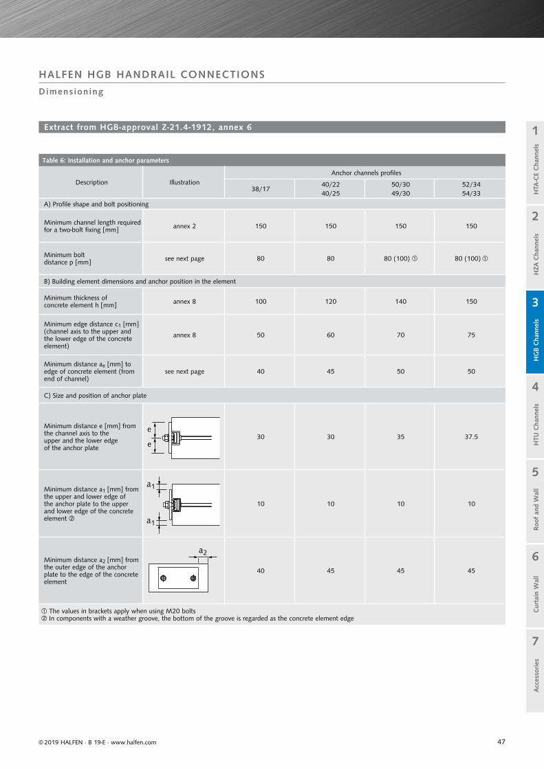
47
Table 6: Installation and anchor parameters
Description IllustrationAnchor channels profiles
38/1740/22 50/30 52/3440/25 49/30 54/33
A) Profile shape and bolt positioning
Minimum channel length required for a two-bolt fixing [mm] annex 2 150 150 150 150
Minimum bolt distance p [mm] see next page 80 80 80 (100) 80 (100)
B) Building element dimensions and anchor position in the element
Minimum thickness ofconcrete element h [mm] annex 8 100 120 140 150
Minimum edge distance c1 [mm] (channel axis to the upper and the lower edge of the concrete element)
annex 8 50 60 70 75
Minimum distance ae [mm] to edge of concrete element (from end of channel)
see next page 40 45 50 50
C) Size and position of anchor plate
Minimum distance e [mm] from the channel axis to the upper and the lower edge of the anchor plate
30 30 35 37.5
Minimum distance a1 [mm] from the upper and lower edge of the anchor plate to the upper and lower edge of the concrete element
10 10 10 10
Minimum distance a2 [mm] from the outer edge of the anchor plate to the edge of the concrete element
40 45 45 45
The values in brackets apply when using M20 bolts In components with a weather groove, the bottom of the groove is regarded as the concrete element edge
e
e
a1
a1
a2
© 2019 HALFEN · B 19-E · www.halfen.com
Cur
tain
Wal
lH
TU C
hann
els
Roo
f an
d W
all
HG
B C
hann
els
1
2
5
4
3
7
6
Acc
esso
ries
H
ZA C
hann
els
HTA
-CE
Cha
nnel
s
HALFEN HGB HANDRAIL CONNECTIONS
Dimens ioning
Extract from HGB-approval Z-21.4-1912, annex 6

48
Table 7: Size and position of required minimum reinforcement
DescriptionAnchor channels
38/17 40/25 49/30 54/33
Stirrup / Quantity3 Ø 8
lb = 200 mm3 Ø 8
lb = 250 mm3 Ø 10
lb = 300 mm3 Ø 12
lb = 400 mm
Edge rebar, top and bottom [mm] Ø 8 Ø 8 Ø 10 Ø 12
Table 9: Design resistance for each bolt
Tensile
Bolts Ø M12 M16 M20
NRd,s,s [kN]
4.6 16.9 31.4 49.0
8.8 44.9 83.7 130.7
A4-, HC-50 14.8 27.4 42.8
A4-70* 31.6 58.8 91.7
Shear
VRd,s,s [kN]
4.6 12.1 22.6 35.2
8.8 27.0 50.2 78.4
A4-, HC-50 10.6 19.8 30.9
A4-70* 22.7 42.2 66.0
* Values also apply for all stainless steels of strength class 70(see also HGB approval, annex 4)
pL ae
© 2019 HALFEN · B 19-E · www.halfen.com
Cur
tain
Wal
lH
TU C
hann
els
Roo
f an
d W
all
HG
B C
hann
els
1
2
5
4
3
7
6
Acc
esso
ries
H
ZA C
hann
els
HTA
-CE
Cha
nnel
s
HALFEN HGB HANDRAIL CONNECTIONS
Dimens ioning
Required minimum reinforcement:One stirrup is placed centrally between the channel anchors and one stirrup directly next to each anchor at the channel ends (if positioned near to the edge, between the anchor and component edge).
Pos. 1
Pos. 2
Stirrup
Edge rebar
Extract; HGB approval Z-21.4-1912, annex 6
Extract; HGB approval Z-21.4-1912, annex 8
Design resistance of concrete pressure zone
where:x = maximum height; concrete pressure zone
(see table 8a and 8b)b = width of pressure zone = width of anchor plate bp
fck = characteristic compression strength of concrete in accordance with EN 206-1:2001-07,for concrete strength ≥ C30/37 only calculate using fck = 30 N/mm²
e = distance between anchor channel axis and outer edge of the anchor plate (see illustration on page 47, table 6)
Mc = 1.5 (partial safety factor)
MRd,c = 0.81 ⋅ x ⋅ b ⋅ fck ⋅ (e − 0.41 ⋅ x)Mc

49
Table 8b: Design resistance of the channel using a two-bolt fixing
Profile 38/17 40/25 49/30 54/33
Minimum thickness of component h [mm] 100 120 140 150
Steel failure (two-bolt fixing)
Tension NRd,s [kN] 15.0 16.7 25.8 45.8
Shear VRd,s [kN] 15.0 16.7 25.8 45.8
Concrete failure (two-bolt fixing)
VRd,c [kN] 6.7 9.0 11.7 12.7
Maximum height of concrete pressure zone x 0.25 ⋅ e 0.25 ⋅ e 0.30 ⋅ e 0.40 ⋅ e
e = distance between the anchor channel axis and outer edges of the anchor plate. For asymmetrical anchor plates the smallest distance to the outer edge of the anchor plate is used for calculation.
Table 8a: Design resistance of the channel using single-bolt fixing
Channel type 38/17 40/25 49/30 54/33
Minimum thickness of component h [mm] 100 120 140 150
Steel failure (single-bolt fixing)
Tension NRd,s [kN] 10.0 11.1 17.2 30.6
Shear VRd,s [kN] 10.0 11.1 17.2 30.6
Concrete failure (single-bolt fixing)
VRd,c [kN] 6.7 9.0 11.7 12.7
Maximum height of concrete pressure zone x 0.25 ⋅ e 0.25 ⋅ e 0.30 ⋅ e 0.40 ⋅ e
c1 e
ec1
bp ae
hp
c1 e
ec1
bp
p ae
hp
© 2019 HALFEN · B 19-E · www.halfen.com
Cur
tain
Wal
lH
TU C
hann
els
Roo
f an
d W
all
HG
B C
hann
els
1
2
5
4
3
7
6
Acc
esso
ries
H
ZA C
hann
els
HTA
-CE
Cha
nnel
sC
urta
in W
all
HTU
Cha
nnel
sRoo
f an
d W
all
HG
B C
hann
els
1
2
5
4
3
7
6
Acc
esso
ries
H
ZA C
hann
els
HTA
-CE
Cha
nnel
s
HALFEN HGB HANDRAIL CONNECTIONS
Dimens ioning
Extract, HGB-approval Z-21.4-1912, annex 8
v1
v2
60
180
VEd
HEd
MEd
e Fw
ev2
ev1ev3
e h1
Fw
v3
h
h p=1
50
c1 e
ec1
bp
p ae
hp
Section Elevation
Dimensioning example HALFEN HGB Guard rail fittings
Level of finished floor
Tota
l hei
ght
MEd = used to calculate applicable moment relative to the channel axis
eV1, eV2, = distance of the vertical loads to e V3 the front edge of the channel
eh1, eFw = distance of the horizontal loads to the front edge of the channel
HEd = used to calculate the applicable horizontal effect
VEd = used to calculate the applicable vertical effect
h, Fw = horizontal load effects
v1, v2, v3 = vertical load effects
bp, hp = anchor plate width and height
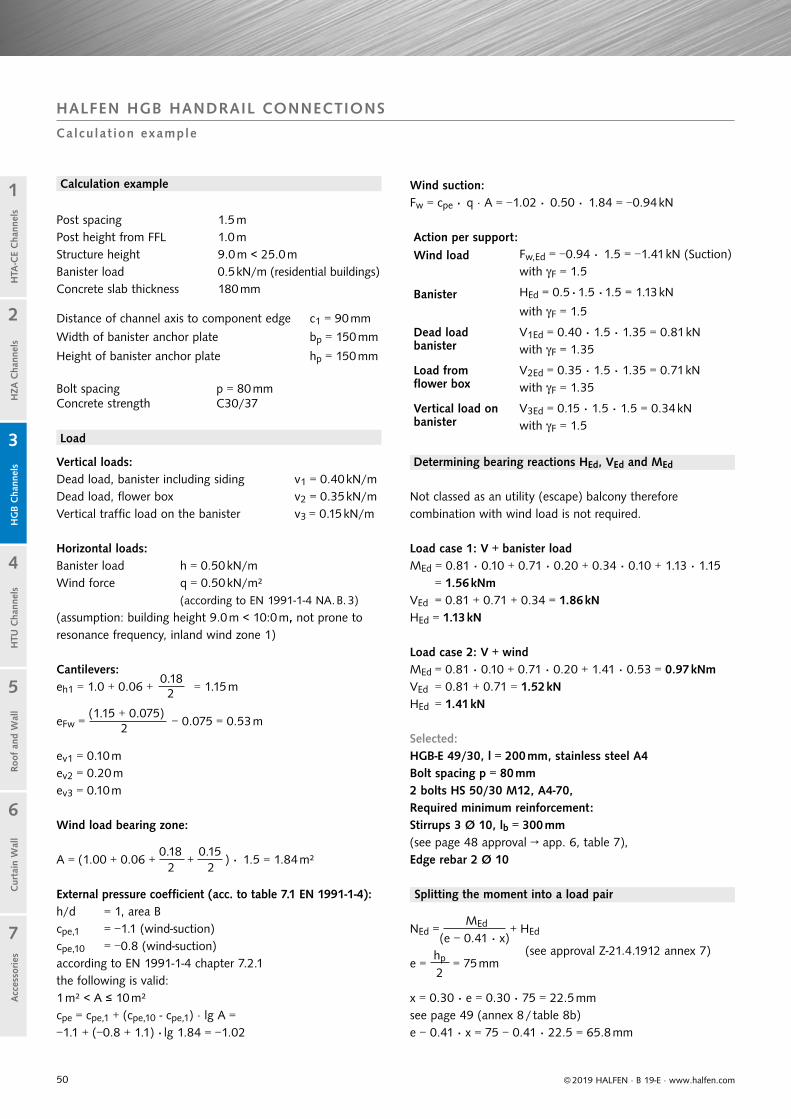
50 © 2019 HALFEN · B 19-E · www.halfen.com
Cur
tain
Wal
lH
TU C
hann
els
Roo
f an
d W
all
HG
B C
hann
els
1
2
5
4
3
7
6
Acc
esso
ries
H
ZA C
hann
els
HTA
-CE
Cha
nnel
s
HALFEN HGB HANDRAIL CONNECTIONS
Calcu lat ion example
Vertical loads:Dead load, banister including siding v1 = 0.40 kN/mDead load, flower box v2 = 0.35 kN/mVertical traffic load on the banister v3 = 0.15 kN/m
Horizontal loads:Banister load h = 0.50 kN/mWind force q = 0.50 kN/m² (according to EN 1991-1-4 NA. B. 3)
(assumption: building height 9.0 m < 10:0 m, not prone to resonance frequency, inland wind zone 1)
Not classed as an utility (escape) balcony therefore combination with wind load is not required.
Load case 1: V + banister load
Cantilevers:
Wind suction:Fw = cpe · q · A = −1.02 · 0.50 · 1.84 = −0.94 kN
External pressure coefficient (acc. to table 7.1 EN 1991-1-4):h/d = 1, area Bcpe,1 = −1.1 (wind-suction)cpe,10 = −0.8 (wind-suction)according to EN 1991-1-4 chapter 7.2.1 the following is valid: 1 m² < A ≤ 10 m² cpe = cpe,1 + (cpe,10 - cpe,1) · lg A =−1.1 + (−0.8 + 1.1) · lg 1.84 = −1.02
eh1 = 1.0 + 0.06 + 0.18
= 1.15 m2
eFw = (1.15 + 0.075)
− 0.075 = 0.53 m2
A = (1.00 + 0.06 + 0.18
+0.15
) · 1.5 = 1.84 m²2 2
ev1 = 0.10 mev2 = 0.20 mev3 = 0.10 m
MEd = 0.81 · 0.10 + 0.71 · 0.20 + 0.34 · 0.10 + 1.13 · 1.15 = 1.56 kNmVEd = 0.81 + 0.71 + 0.34 = 1.86 kNHEd = 1.13 kN
Wind load bearing zone:
Load case 2: V + wind
Selected:HGB-E 49/30, l = 200 mm, stainless steel A4Bolt spacing p = 80 mm2 bolts HS 50/30 M12, A4-70,Required minimum reinforcement: Stirrups 3 Ø 10, lb = 300 mm (see page 48 approval → app. 6, table 7), Edge rebar 2 Ø 10
MEd = 0.81 · 0.10 + 0.71 · 0.20 + 1.41 · 0.53 = 0.97 kNmVEd = 0.81 + 0.71 = 1.52 kNHEd = 1.41 kN
Splitting the moment into a load pair
(see approval Z-21.4.1912 annex 7)
Load
Post spacing 1.5 mPost height from FFL 1.0 mStructure height 9.0 m < 25.0 mBanister load 0.5 kN/m (residential buildings)Concrete slab thickness 180 mm
Distance of channel axis to component edge c1 = 90 mm
Width of banister anchor plate bp = 150 mm
Height of banister anchor plate hp = 150 mm
Bolt spacing p = 80 mmConcrete strength C30/37
Calculation example
NEd = MEd + HEd(e − 0.41 · x)
e = hp = 75 mm2
x = 0.30 ⋅ e = 0.30 ⋅ 75 = 22.5 mm see page 49 (annex 8 / table 8b)e − 0.41 ⋅ x = 75 − 0.41 ⋅ 22.5 = 65.8 mm
Action per support:Wind load Fw,Ed = −0.94 · 1.5 = −1.41 kN (Suction)
with F = 1.5
Banister HEd = 0.5 ·1.5 ·1.5 = 1.13 kN
with F = 1.5
Dead load banister
V1Ed = 0.40 · 1.5 ⋅ 1.35 = 0.81 kN with F = 1.35
Load from flower box
V2Ed = 0.35 · 1.5 ⋅ 1.35 = 0.71 kN with F = 1.35
Vertical load on banister
V3Ed = 0.15 · 1.5 ⋅ 1.5 = 0.34 kN with F = 1.5
Determining bearing reactions HEd, VEd and MEd

51© 2019 HALFEN · B 19-E · www.halfen.com
Cur
tain
Wal
lH
TU C
hann
els
Roo
f an
d W
all
HG
B C
hann
els
1
2
5
4
3
7
6
Acc
esso
ries
H
ZA C
hann
els
HTA
-CE
Cha
nnel
s
HALFEN HGB HANDRAIL CONNECTIONS
Calcu lat ion example
Load case 2: V + wind
Channel, centric pull load
Bolt, centric pull load
Bolt, shear load
Bolt, interaction
Verification of concrete capacity Design resistance concrete
Concrete edge failure
Channel, shear load
Channel, interaction
Design resistance (steel) bolt M12, A4-70NRd,s,s = 31.6 kNVRd,s,s = 22.7 kN
Verification of steel capacity
Geometrical boundry conditions according to approvalZ-21.4-1912 annex 6, table 6 have been met.
Design resistance (steel) channel HGB 49/30 using 2 bolt fixingNRd,s = 25.8 kNVRd,s = 25.8 kN
VEd = 1.86 kN → decisive
VEd = 1.52 kN
NEd = 1.56 kNm
+ 1.13 kN = 24.84 kN → decisive0.0658 m
NEd = 0.98 kNm
+ 1.41 kN = 16.30 kN0.0658 m
NEd = 24.84
= 0.96 < 1
VEd = 1.86
= 0.07 < 1
NRd,s
VRd,s
= 0.93 + 0.01 = 0.94 < 1
NRd,s,s 31.60.5 ⋅
NEd = 0.5 ⋅
24.84
= 0.39 < 1
VRd,s,s 22.70.5 ⋅
VEd =
0.5 ⋅ 1.86
= 0.04 < 1
= 3.60 kNm
VEd = 1.86
= 0.16 < 1VRd,c 11.7
VEd = 0.16 < 0.333 VRd,c
MEd = 1.56
= 0.43 < 1MRd,c 3.60
→ According to the approval verifica-tion of interaction is not required, see page 46 (approval / page 7).
Verifying the ratio between horizontal action and bending moment
→ Design model is applicable see page 46 (approval / page 7)
HEd = 1.13 kN
= 0.72 < 1.5 1.56 kNmMEd
Load case 1: V + banister load
25.8
25.8
MRd,c = 0.81 ⋅ x ⋅ b ⋅
fck ⋅ (e − 0.41 ⋅ x)Mc
MRd,c = 0.81 ⋅ 22.5 ⋅ 150 ⋅
30 ⋅ 65.8
= 3 597 615 Nmm
1.5
see page 48 (annex 8, table 8b)
see page 48 (annex 8, tab. 9)
VRd,c = 11.7 kN see page 49 (annex 8, table 8b)
( NEd )2 + ( VEd
)2 = ( 24.84 )2 + ( 1.86 )2 NRd,s VRd,s 25.8 25.8
NRd,s,s VRd,s,s( 0.5 ⋅
NEd )
2 + (
0.5 ⋅ VEd )
2 = 0.392 + 0.042 = 0.15 < 1
Verifications

52 © 2019 HALFEN · B 19-E · www.halfen.com
Cur
tain
Wal
lH
TU C
hann
els
Roo
f an
d W
all
HG
B C
hann
els
1
2
5
4
3
7
6
Acc
esso
ries
H
ZA C
hann
els
HTA
-CE
Cha
nnel
s
HALFEN HTU Cast-in channels
Anchor design AN
HALFEN HTU Cast-in channels
Anchor design D
T he perfect technical solutionfor attaching trapezoidal steel
sheet to concrete. HALFEN HTU Cast-in channels and self-tapping screws have become a standard everyday solution in the construction industry.
Quick and cost-effective
• simple installation
• quick and easy installation of trapezoidal sheeting
• two anchor designs, AN and D for optimal adapting to plannedreinforcement
Safe and reliable
• optimal shape of the anchoringelements means safe and low slip anchorage
• the polystyrene-filler preventsthe drill or self-tapping-screwshitting concrete
• building authority approved
HALFEN HTU Cast-in channelsThe advantages at a glance
HTU
cast-
in channel
officially app
rove
d
App. No Z - 21.4 - 8
4

53
Cur
tain
Wal
lH
TU C
hann
els
Roo
f an
d W
all
HG
B C
hann
els
1
2
5
4
3
7
6
Acc
esso
ries
© 2019 HALFEN · B 19-E · www.halfen.com
HZA
Cha
nnel
sH
TA-C
E C
hann
els
Fixing trapezoidal sheet metal using self-tapping screws
Vertical HALFEN HTU Cast-in channels for connecting façade panels
Installing HALFEN HTU Cast-in channels in the front face of a slab
HALFEN HTU Cast-in channels in a pre-stressed concrete beam
Façade fixed using HALFEN HTU Cast-in channels
HALFEN HTU CAST- IN CHANNELS
Appl icat ion Examples
Fixing of trapezoidal sheet metal roofing
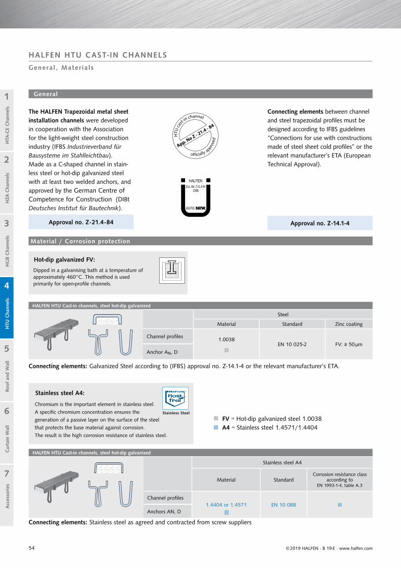
54
HALFEN HTU Cast-in channels, steel hot-dip galvanized
Steel
Material Standard Zinc coating
Channel profiles 1.0038 EN 10 025-2 FV: ≥ 50 μm
Anchor AN, D
HALFEN HTU Cast-in channels, steel hot-dip galvanized
Stainless steel A4
Material StandardCorrosion resistance class
according to EN 1993-1-4, table A.3
Channel profiles1.4404 or 1.4571 EN 10 088 III
Anchors AN, D
Z-21.4-84
© 2019 HALFEN · B 19-E · www.halfen.com
Cur
tain
Wal
lH
TU C
hann
els
Roo
f an
d W
all
HG
B C
hann
els
1
2
5
4
3
7
6
Acc
esso
ries
H
ZA C
hann
els
HTA
-CE
Cha
nnel
s
Material / Corrosion protection
The HALFEN Trapezoidal metal sheet installation channels were developed in cooperation with the Association for the light-weight steel construction industry (IFBS Industrieverband für Bausysteme im Stahlleichtbau). Made as a C-shaped channel in stain-less steel or hot-dip galvanized steel with at least two welded anchors, and approved by the German Centre of Competence for Construction (DIBt Deutsches Institut für Bautechnik).
Approval no. Z -21.4-84
Connecting elements between channel and steel trapezoidal profiles must be designed according to IFBS guidelines “Connections for use with constructions made of steel sheet cold profiles” or the relevant manufacturer’s ETA (European Technical Approval).
General
FV = Hot-dip galvanized steel 1.0038A4 = Stainless steel 1.4571/1.4404
Approval no. Z -14.1-4
Connecting elements: Stainless steel as agreed and contracted from screw suppliers
Connecting elements: Galvanized Steel according to (IFBS) approval no. Z-14.1-4 or the relevant manufacturer’s ETA.
HALFEN HTU CAST- IN CHANNELS
Genera l , Mater ia ls
Dipped in a galvanising bath at a temperature of approximately 460°C. This method is used primarily for open-profile channels.
Hot-dip galvanized FV:
Stainless steel A4:
Chromium is the important element in stainless steel.
A specific chromium concentration ensures the
generation of a passive layer on the surface of the steel
that protects the base material against corrosion.
The result is the high corrosion resistance of stainless steel.
HTU
cast-
in channel
officially app
rove
d
App. No Z - 21.4 - 8
4
Stainless Steel
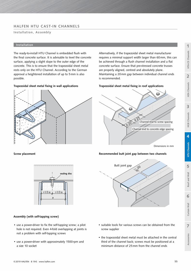
55
≥ 20
≥ 25
≥≥≥ 2≥ 2222
20
>1/3 a >1/3 a
a
Cur
tain
Wal
lH
TU C
hann
els
Roo
f an
d W
all
HG
B C
hann
els
1
2
5
4
3
7
6
Acc
esso
ries
© 2019 HALFEN · B 19-E · www.halfen.com
HZA
Cha
nnel
sH
TA-C
E C
hann
els
Installation
Recommended butt joint gap between two channels
The ready-to-install HTU Channel is embedded flush with the final concrete surface. It is advisable to level the concrete surface, applying a slight slope to the outer edge of the concrete. This is to ensure that the trapezoidal sheet metal rests only on the HTU Channel. According to the German approval a heightened installation of up to 5 mm is also possible.
Alternatively, if the trapezoidal sheet metal manufacturer requires a minimal support width larger than 60 mm, this can be achieved through a flush channel installation and a flat concrete surface. Ensure that pre-stressed concrete trusses are properly aligned, centred and absolutely plane. Maintaining a 20 mm gap between individual channel ends is recommended.
Assembly (with self-tapping screw)
Trapezoidal sheet metal fixing in wall applications
Dimensions in mm
HALFEN HTU CAST- IN CHANNELS
Ins ta l la t ion, Assembly
Butt joint gap
Channel end to screw spacing
Channel end to concrete edge spacing
Screw placement
Trapezoidal sheet metal fixing in roof applications
• use a power-driver to fix the self-tapping screw; a pilot hole is not required. Even 4-fold overlapping at joints is not a problem with self-tapping screws
• use a power-driver with approximately 1500 rpm and a size 10 socket
• suitable tools for various screws can be obtained from the screw supplier
• the trapezoidal sheet metal must be attached in the central third of the channel back; screws must be positioned at a minimum distance of 25 mm from the channel ends
sealing disc

56
HTU 60/22/6 Number of anchors = hot-dip galvanized
HTU 60/22/6 - AN2 - FV - 3000 - Sf 8
HTU 60/22/6 - D2 - FV - 3000 - Sf 8
HTU 60/22/6 - AN3 - FV - 3000 - Sf 20
HTU 60/22/6 - D3 - FV - 3000 - Sf 20
= Stainless steel A4
HTU 60/22/3 - AN2 - A4 - 3000 - Sf 8
HTU 60/22/3 - D2 - A4 - 3000 - Sf 8
HTU 60/22/3 - AN3 - A4 - 3000 - Sf 20
HTU 60/22/3 - D3 - A4 - 3000 - Sf 20
HTU 60/22/3 Number of anchors = hot-dip galvanized
HTU 60/22/3 - AN2 - FV - 3000 - Sf 8
HTU 60/22/3 - D2 - FV - 3000 - Sf 8
HTU 60/22/3 - AN3 - FV - 3000 - Sf 20
HTU 60/22/3 - D3 - FV - 3000 - Sf 20
Profile cross-section A 2.81 cm² 4.94 cm²
Moment of inertia ly / Moment of resistance wy 1.13 cm4 / 0.71 cm³ 1.84 cm4 / 1.27 cm³
Profile weight including anchors 2.49 kg/m 2.50 kg/m 4.25 kg/m 4.26 kg/m
Configuration AN Configuration D Configuration AN Configuration D
60
100
22
3
60
100
22
6
© 2019 HALFEN · B 19-E · www.halfen.com
Cur
tain
Wal
lH
TU C
hann
els
Roo
f an
d W
all
HG
B C
hann
els
1
2
5
4
3
7
6
Acc
esso
ries
H
ZA C
hann
els
HTA
-CE
Cha
nnel
s
HALFEN HTU CAST- IN CHANNEL
Product Range
Material A4 available only in 3 mm thickness Dimensions in [mm]
Identification HTU
Type D2 or AN2
Type D3 or AN3
Anchor spacing:
Ordering example:
HTU 60/22/3 - D2 - FV - 3000 - Sf
type / profile
anchor configuration
material / finish
length [mm]
polystyrene strip filler
FV = Steel S235JR, hot-dip galvanizedA4 = Stainless steel 1.4571/1.4404
HTU
cast-
in channel
officially app
rove
d
App. No Z - 21.4 - 8
4HTU 60/22/3 Type AN(Steel 1.0038 1.4404/1.4571, thickness 3 mm)
for screw-fastening of trapezoidal sheet metalwith hex-headed sheet metal or self-tapping screws
A yellow identification label is fixed to the back of each channel.
Connecting element HTU material stainless steelchannel thickness 3 mm
e.g. JT3-3H-5,5x25-E16 with 4.5 mm pre-drilled or JZ7-6,3x22-E16 with 5.3 mm pre-drilled. .
- no approval - Coordination with the screw suppliers is required
Connecting element HTU material steelETA 10/0200:
Self-tapping screws 6.3×19 e.g. JT2-6-6,3-19-xE16 with sealing disc.
Connecting element is exposed to weather: JT3-6-6.3x25-E16 (Wall) or JZ3-6-6.3x25-E22 (Roof)
Connecting element HTU material steelETA 10/0200: Self-tapping screws 6.3×22
e.g. JT2-6-6,3-x22-V16 with sealing discor cartridge fired nails SBR-14.
Connecting element is exposed to weather: see left
Type HTU 60/22/3 Type HTU 60/22/6
63.5
75
60
6
63.5
75
60
3
63.5
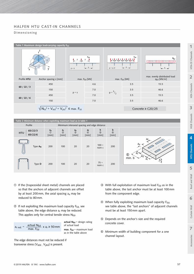
57
Table 1 Maximum design load-carrying capacity FEd
Profile HTU Anchor spacing s [mm] max. FEd [kN] max. FEd [kN]max. evenly distributed load
qEd [kN/m]
60 / 22 / 3450
p = s
4.6
p = s/2
3.5 15.5
150 7.0 3.5 46.6
60 / 22 / 6450 7.0 3.5 15.5
150 7.0 3.5 46.6
Table 2 Minimum distance when exploiting maximum load as in table 1
Profile Minimum interaxial spacing and edge distance
HTU60/22/3
60/22/6
���
aa
[mm]
ar
[mm]
ae
[mm]
af
[mm]
h
[mm]
b
[mm]
h
af
ae
ar
araamin. b
Type AN 200 100 20 20 100 + nom c 200
Type D 200 100 20 20 75 + nom c 200
NEd2 + VxEd
2 + VyEd2 ≤ max. FEd
s s
pp
p s s
p p p p p p
py
z
xs
qEd
© 2019 HALFEN · B 19-E · www.halfen.com
Cur
tain
Wal
lH
TU C
hann
els
Roo
f an
d W
all
HG
B C
hann
els
1
2
5
4
3
7
6
Acc
esso
ries
H
ZA C
hann
els
HTA
-CE
Cha
nnel
s
If the (trapezoidal sheet metal) channels are placed so that the anchors of adjacent channels are offsetby at least 200 mm, the axial spacing aa may bereduced to 80 mm.
If not exploiting the maximum load capacity FEd, see table above, the edge distance ar may be reduced.This applies only for central tensile stress NEd.
actual NEd = design rating of actual load
max. FEd = maximum load as in the table above
With full exploitation of maximum load FEd as in the table above, the last anchor must be at least 100 mm from the component edge.
When fully exploiting maximum load capacity FEd, see table above, the “last anchors” of adjacent channels must be at least 150 mm apart.
Depends on the anchor‘s size and the required concrete cover.
Minimum width of building component for a one channel layout.
The edge distances must not be reduced if transverse stress (VxEd , VyEd) is present.
HALFEN HTU CAST- IN CHANNELS
Dimens ioning
ar red. = x ar ≥ 50 mmactual NEdmax. FEd
Concrete ≥ C20/25
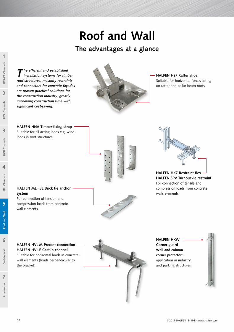
58 © 2019 HALFEN · B 19-E · www.halfen.com
Cur
tain
Wal
lH
TU C
hann
els
Roo
f an
d W
all
HG
B C
hann
els
1
2
5
4
3
7
6
Acc
esso
ries
H
ZA C
hann
els
HTA
-CE
Cha
nnel
s
HALFEN HKZ Restraint tiesHALFEN SPV Turnbuckle restraintFor connection of tensile and compression loads from concrete walls elements.
HALFEN HSF Rafter shoeSuitable for horizontal forces acting on rafter and collar beam roofs.
HALFEN HKW Corner guardWall and column corner protector; application in industry and parking structures.
HALFEN HVL-M Precast connectionHALFEN HVL-E Cast-in channelSuitable for horizontal loads in concrete wall elements (loads perpendicular to the bracket).
HALFEN HNA Timber fi xing strapSuitable for all acting loads e.g. wind loads in roof structures.
T he effi cient and established installation systems for timber
roof structures, masonry restraints and connectors for concrete façades are proven practical solutions for the construction industry, greatly improving construction time with signifi cant cost-saving.
Roof and WallThe advantages at a glance
HALFEN ML+BL Brick tie anchor systemFor connection of tension and compression loads from concrete wall elements.

59
Cur
tain
Wal
lH
TU C
hann
els
Roo
f an
d W
all
HG
B C
hann
els
1
2
5
4
3
7
6
Acc
esso
ries
© 2019 HALFEN · B 19-E · www.halfen.com
HZA
Cha
nnel
sH
TA-C
E C
hann
els
HALFEN HTU CAST- IN CHANNELS
Appl icat ion Examples
HALFEN HSF Rafter shoe 6/12 HALFEN HKZ Restraint tie with serrated washer
Airbus paintshop with HALFEN HVL Restraint tie HVL-System in precast building components
Connecting construction timbers to concrete using the HNA Timber roof construction with HALFEN HNA Fixing straps
HALFEN ML Brick-tie anchor systemCorner guards in an industrial environment
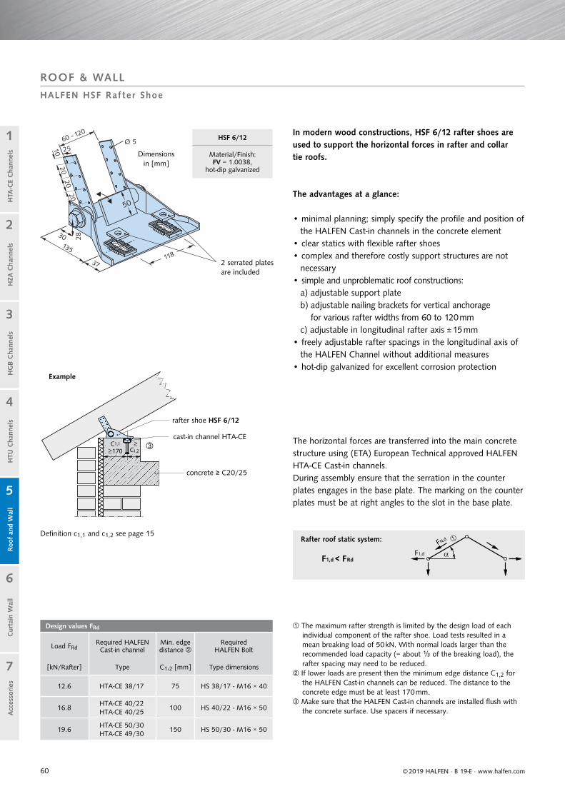
60
Design values FRd
Load FRdRequired HALFEN Cast-in channel
Min. edge distance
Required HALFEN Bolt
[kN/Rafter] Type C1,2 [mm] Type dimensions
12.6 HTA-CE 38/17 75 HS 38/17 - M16 × 40
16.8HTA-CE 40/22 HTA-CE 40/25
100 HS 40/22 - M16 × 50
19.6HTA-CE 50/30 HTA-CE 49/30
150 HS 50/30 - M16 × 50
C1,2C1,1
170
F1,d FN,d
© 2019 HALFEN · B 19-E · www.halfen.com
Cur
tain
Wal
lH
TU C
hann
els
Roo
f an
d W
all
HG
B C
hann
els
1
2
5
4
3
7
6
Acc
esso
ries
H
ZA C
hann
els
HTA
-CE
Cha
nnel
s
In modern wood constructions, HSF 6/12 rafter shoes are used to support the horizontal forces in rafter and collar tie roofs.
The advantages at a glance:
• minimal planning; simply specify the profile and position of the HALFEN Cast-in channels in the concrete element
• clear statics with flexible rafter shoes• complex and therefore costly support structures are not
necessary• simple and unproblematic roof constructions:
a) adjustable support plateb) adjustable nailing brackets for vertical anchorage
for various rafter widths from 60 to 120 mm c) adjustable in longitudinal rafter axis ± 15 mm• freely adjustable rafter spacings in the longitudinal axis of
the HALFEN Channel without additional measures• hot-dip galvanized for excellent corrosion protection
The horizontal forces are transferred into the main concrete structure using (ETA) European Technical approved HALFEN HTA-CE Cast-in channels.During assembly ensure that the serration in the counter plates engages in the base plate. The marking on the counter plates must be at right angles to the slot in the base plate.
The maximum rafter strength is limited by the design load of each individual component of the rafter shoe. Load tests resulted in a mean breaking load of 50 kN. With normal loads larger than the recommended load capacity (= about ⅓ of the breaking load), the rafter spacing may need to be reduced.
If lower loads are present then the minimum edge distance C1,2 for the HALFEN Cast-in channels can be reduced. The distance to the concrete edge must be at least 170 mm.
Make sure that the HALFEN Cast-in channels are installed flush with the concrete surface. Use spacers if necessary.
Example
Dimensionsin [mm]
2 serrated plates are included
rafter shoe HSF 6/12
Rafter roof static system:
F1,d < FRd
ROOF & WALL
HALFEN HSF Raf ter Shoe
HSF 6/12
Material/Finish:FV = 1.0038,
hot-dip galvanized
cast-in channel HTA-CE
concrete ≥ C20/25
Definition c1,1 and c1,2 see page 15
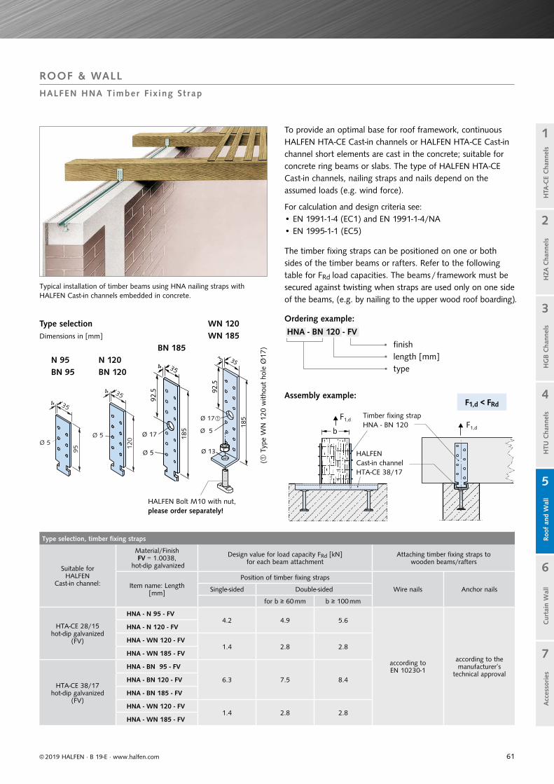
61
Type selection, timber fixing straps
Suitable forHALFEN
Cast-in channel:
Material/FinishFV = 1.0038,
hot-dip galvanized
Design value for load capacity FRd [kN] for each beam attachment
Attaching timber fixing straps towooden beams/rafters
Item name: Length[mm]
Position of timber fixing straps
Wire nails Anchor nailsSingle-sided Double-sided
for b ≥ 60 mm b ≥ 100 mm
HTA-CE 28/15hot-dip galvanized
(FV)
HNA - N 95 - FV4.2 4.9 5.6
according to EN 10230-1
according to the manufacturer’s
technical approval
HNA - N 120 - FV
HNA - WN 120 - FV1.4 2.8 2.8
HNA - WN 185 - FV
HTA-CE 38/17hot-dip galvanized
(FV)
HNA - BN 95 - FV
6.3 7.5 8.4HNA - BN 120 - FV
HNA - BN 185 - FV
HNA - WN 120 - FV1.4 2.8 2.8
HNA - WN 185 - FV
F1,d
bF1,d
F1,d < FRd
Cur
tain
Wal
lH
TU C
hann
els
Roo
f an
d W
all
HG
B C
hann
els
1
2
5
4
3
7
6
Acc
esso
ries
© 2019 HALFEN · B 19-E · www.halfen.com
HZA
Cha
nnel
sH
TA-C
E C
hann
els
The timber fixing straps can be positioned on one or both sides of the timber beams or rafters. Refer to the following table for FRd load capacities. The beams / framework must be secured against twisting when straps are used only on one side of the beams, (e.g. by nailing to the upper wood roof boarding).
For calculation and design criteria see:• EN 1991-1-4 (EC1) and EN 1991-1-4/NA• EN 1995-1-1 (EC5)
To provide an optimal base for roof framework, continuous HALFEN HTA-CE Cast-in channels or HALFEN HTA-CE Cast-in channel short elements are cast in the concrete; suitable for concrete ring beams or slabs. The type of HALFEN HTA-CE Cast-in channels, nailing straps and nails depend on the assumed loads (e.g. wind force).
Typical installation of timber beams using HNA nailing straps withHALFEN Cast-in channels embedded in concrete.
Type selection Dimensions in [mm]
N 95BN 95
N 120BN 120
BN 185
WN 120WN 185
Ordering example:
HNA - BN 120 - FV finishlength [mm]type
Assembly example:
HALFEN Bolt M10 with nut, please order separately!
( T
ype
WN
120
with
out
hole
Ø17
)
Timber fixing strap HNA - BN 120
HALFEN Cast-in channelHTA-CE 38/17
ROOF & WALL
HALFEN HNA Timber F ix ing St rap
92.5 92
.5
353

62
FZ,Ed
FQ,Ed
l
a d
FZ,Ed
l
HMS 25/15 D
ML
ML
HM 28/15
l
l
HTA-CE 28/15
ML
© 2019 HALFEN · B 19-E · www.halfen.com
Cur
tain
Wal
lH
TU C
hann
els
Roo
f an
d W
all
HG
B C
hann
els
1
2
5
4
3
7
6
Acc
esso
ries
H
ZA C
hann
els
HTA
-CE
Cha
nnel
s
Plan view; attachment of facing brickworkPlan view; wall attachment
All HTA-CE and HMS profiles have a foam filling to prevent concrete ingress. The channels are attached to the form-work using standard nails.
Brick tie anchor ML in combination with HALFEN Cast-in channels 25/15-D and 28/15
spacing a - see FM Catalogue
Installation channel HM welded to steel supports
Embedded HTA-CE Cast-in channel
ETA approved
HMS Cast-in channel with Brick-tie anchor
ROOF & WALL
Br ick T ie Anchor Sys tems ML + BL
Lug anchors are bent out on site by hand every 250 mm to ensure secure anchorage in the concrete.
1. Attach to formwork
2. Bend out lug anchors
3. Pour the concrete
The HALFEN Brick tie anchors are inserted at the recommended intervals (static requirements) in the brick wall during construction (see page 65). The anchors are inserted in the brick tie channels, laid flat between the rows of brick and pressed into the mortar. The perforations in the anchors optimise anchorage with the mortar.
HALFEN ML and BL Brick tie anchors are tried and tested efficient instal-lation systems for securing brick walls, masonry in-fills, partition walls, brick renders (with or without ventilation gap and heat insulation) to concrete
walls, concrete supports, steel or wooden structures.The brick tie anchors are able to move freely in the brick tie channels, considerably reducing cracks caused by masonry settlement.
Embedded length e
Embedded length e ≥ 50 mm

63
HL 28/15
HL 28/15
HL 28/15
HB-VMU-A+SH
HB-VMU-A
HB-BZ-U 8-15-26/80
l1
ETA-17/01961
ETA-16/0691
15
9
25
Cur
tain
Wal
lH
TU C
hann
els
Roo
f an
d W
all
HG
B C
hann
els
1
2
5
4
3
7
6
Acc
esso
ries
© 2019 HALFEN · B 19-E · www.halfen.com
HZA
Cha
nnel
sH
TA-C
E C
hann
els
HL slotted framing channels anchored to concrete or masonry
Top view
For more information on application and assembly
see the Technical Product Information catalogue,
HALFEN HB Anchor bolt systems
Bolt anchor HB-BZ-U 8-15-26/80
Anchor rod HB -VMU-A 8-20/110
• galvanized or stainless steel (A4)• approved for cracked and uncracked concrete• with large washer DIN 9021/EN ISO 7093• mortar cartridge HB-VMU plus 280 and static mixer
(order separately)
ROOF & WALL
Br ick T ie Anchor Sys tems, ML + BL HALFEN Anchor Bol t Sys tems
• galvanized or stainless steel (A4)• approved for monolithic masonry• with large washer DIN 9021/EN ISO 7093
(order separately)
• galvanized or stainless steel (A4)• approved for perforated brick masonry• with large washer DIN 9021/EN ISO 7093
(order separately)• mortar cartridge HB-VMU plus 280 and static
mixer (order separately)
Anchor rod HB-VMU-A 8-20/110 with Perforated sleeve HB-VMU-SH 16×85
a = static requirements
ETA 17/0196 (brickwork) and ETA 16/0691 (concrete)/ Injection system HB-VMU plus
large washer; order separately
large washer; order separately
HALFEN Dowel
HL 28/15
MLEuropean Technical Assessment-Option 1
European Technical Assessment-Option 1

64
Brick tie anchor
HMS 25/15 DL = 2500 mm
HTA-CE 28/15
L = 1050 mm
L = 6070 mm
HL 28/15L = 6070 mm
HTA-CE 38/17
L = 1050 mm
L = 6070 mm
Brick tie anchor
MLStandard
26 × 2 [mm]
ML1
25 × 1.25 [mm]
MLQ - D Double-sided
25 × 3 [mm]
MLQ - E Single-sided
25 × 3 [mm]
MLSSlanted
22 × 3 [mm]
Type Length l[mm] Type Length l
[mm] Type Length l [mm] Type Length l
[mm] Type Length l1[mm]
ML - 85 ML 1 - 125 MLQ-D - 85 MLQ-E - 85 MLS - 300
ML - 120 ML 1 - 185 MLQ-D - 120 MLQ-E - 120 MLS - 350
ML - 180 ML 1 - 245 MLQ-D - 180 MLQ-E - 180 MLS - 400
BLStandard
30 × 2 [mm]
BLQ - D Double-sided
30 × 3 [mm]
BLQ - E Single-sided
30 × 3 [mm]
Other lengths: Thickness in the overlap area: 6 mm (2×3 mm)
Type Length l [mm] Type Length l
[mm] Type Length l[mm]
BL - 85 BLQ-D - 85 BLQ-E - 85
BL - 120 BLQ-D - 120 BLQ-E - 120
BL - 180 BLQ-D - 180 BLQ-E - 180
15
75
25
17
50 (74)
38
15
48
28
lStandard
FZ,Ed
FQ,Ed
b(3
00)
l
FZ,Ed
FQ,Ed
l
b1(1
50)
FZ,Ed
FQ,Edl1
Fz,Ed
FQ,Ed
l
FZ,Ed
FQ,Ed
30
150
ML-G 150
ML
ML 1
15
28
ML, BL
ML 1
l
HTA-CE 38/17
BL
© 2019 HALFEN · B 19-E · www.halfen.com
Cur
tain
Wal
lH
TU C
hann
els
Roo
f an
d W
all
HG
B C
hann
els
1
2
5
4
3
7
6
Acc
esso
ries
H
ZA C
hann
els
HTA
-CE
Cha
nnel
s
• max. load FZ,Ed = 0.32 kN per cm embedment length e
• max. FZ,Ed ≤ 3.2 kN= Fz,Rd• max. FQ,Ed ≤ 2.7 kN= FQ,Rd
Masonry connectionwith ML 1
Masonry connection with BL
Debond sleeve ML-G 150 for wall attachments, suitable for ML-anchors
Permits movement in the longitudinal anchor direction, e.g. in long masonry bonds or partition walls adjoining concrete load bearing structures; prevents cracks forming.
ML-G 150, material: soft PVC, material thickness 1.5 mm
ROOF & WALL
Br ick T ie Anchor Sys tems ML + BL
Available on request
Material:
FV = Steel 1.0038, hot-dip galvanized
SV = Steel DX51D + Z275, sendzimir galvanized
A4 = Stainless steel1.4571/1.4404
A2 = Stainless steel 1.4307
Observe profile load capacity!
double-sided single-sided
( can be used alternatively)
( can be used alternatively)
angled
• max. FZ,Ed ≤ 2.5 kN= Fz,Rd• max. FQ,Ed ≤ 1.4 kN = FQ,Rd
Brick tie anchors
1.25mm
HTA-CE 28/15
ML 1
l

65
HALFEN Cast-in channel
type
Brick tie anchor (see page 62 ff.)
for standard mortar for thin bed mortar
HMS 25/15 D ML ML 1
HTA 28/15 ML ML 1
HTA 38/17 BL –
Cur
tain
Wal
lH
TU C
hann
els
Roo
f an
d W
all
HG
B C
hann
els
1
2
5
4
3
7
6
Acc
esso
ries
© 2019 HALFEN · B 19-E · www.halfen.com
HZA
Cha
nnel
sH
TA-C
E C
hann
els
Solid masonry fire wallsStatically required connections of load bearing, room enclosing, masonry walls can also be designed as fire walls in accordance with DIN 4102-4 section 9.8.4 using HALFEN Brick tie channels.The anchorage to adjacent components (steel reinforced concrete supports or walls) meet the requirements for stability and fire resistance if the anchorage conforms to the standards set in DIN 4102-4 section 9.8.4 (figure 9.13, variant 2).
Definition, DIN regulations
HALFEN Cast-in channel
Insulation layer: According to DIN 4102-4 section 9.2.14 insulation layers in connecting joint gaps must “[...] be made of non-flamm-able mineral fibre; have a melting point ≥ 1000°C as stated in DIN 4102-17; and have a gross density of≥ 30 kg/m³ and must not smoulder”.
Masonry: Bricks (gross density class) and minimum wall thickness according to EN 1996-1-2: 2011-04.
Masonry connection (vertically adjustable) Expansion joint Concrete
Product information
Anchor spacingsHALFEN Brick tie anchors can be used at any position along the whole length of the brick tie channel. Generally the standard spacing between the anchors is 250 mm (4 anchors per metre).
ROOF & WALL
Firewal l Connect ions with Wal l Connect ing Sys tems ML + BL
Firewall connection according to DIN 4102-4: 2016-05
Vertical section
Horizontal section Connection of a load bearing masonry wall as a fire wall according to DIN 4102-4 section 9.8.4 (figure 9.13) or according to EN 1996-1-2: 2011-04 (figure E.4B)
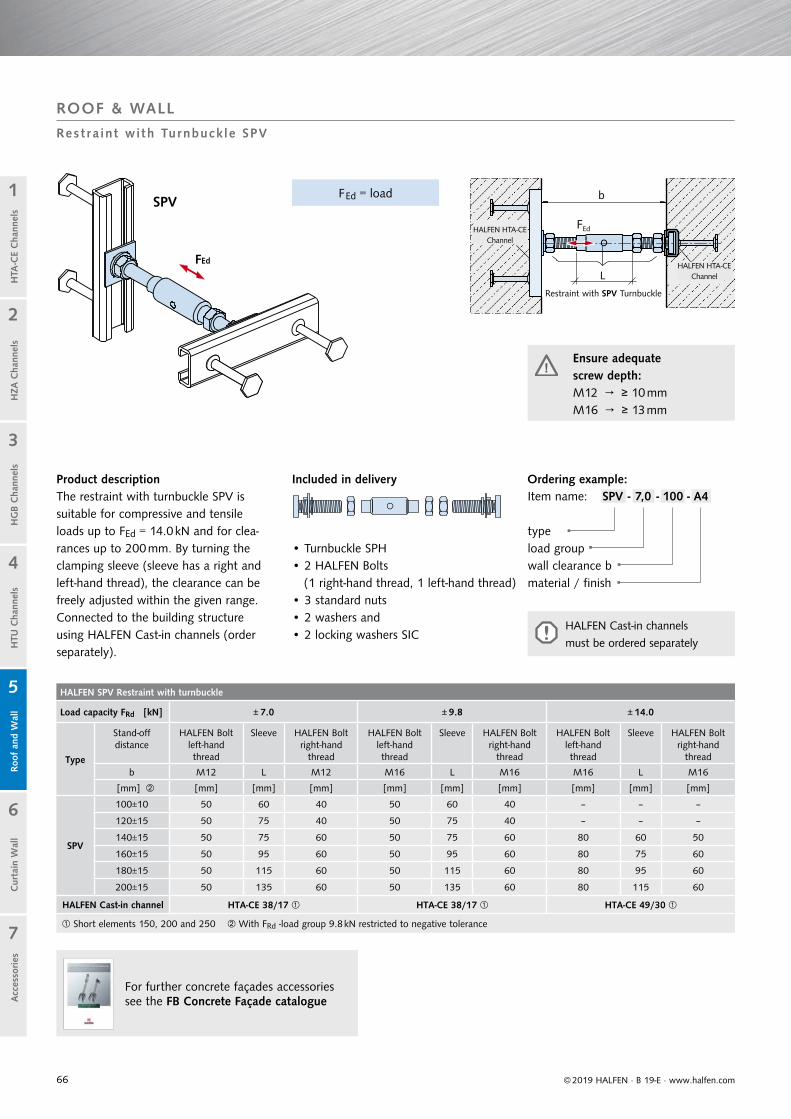
66
HALFEN SPV Restraint with turnbuckle
Load capacity FRd [kN] ± 7.0 ± 9.8 ± 14.0
Type
Stand-offdistance
HALFEN Bolt left-hand thread
Sleeve HALFEN Bolt right-hand
thread
HALFEN Bolt left-hand thread
Sleeve HALFEN Bolt right-hand
thread
HALFEN Bolt left-hand thread
Sleeve HALFEN Bolt right-hand
thread
b M12 L M12 M16 L M16 M16 L M16
[mm] [mm] [mm] [mm] [mm] [mm] [mm] [mm] [mm] [mm]
SPV
100±10 50 60 40 50 60 40 – – –
120±15 50 75 40 50 75 40 – – –
140±15 50 75 60 50 75 60 80 60 50
160±15 50 95 60 50 95 60 80 75 60
180±15 50 115 60 50 115 60 80 95 60
200±15 50 135 60 50 135 60 80 115 60
HALFEN Cast-in channel HTA-CE 38/17 HTA-CE 38/17 HTA-CE 49/30
Short elements 150, 200 and 250 With FRd -load group 9.8 kN restricted to negative tolerance
For further concrete façades accessories see the FB Concrete Façade catalogue
b
FEd
LFEd
© 2019 HALFEN · B 19-E · www.halfen.com
Cur
tain
Wal
lH
TU C
hann
els
Roo
f an
d W
all
HG
B C
hann
els
1
2
5
4
3
7
6
Acc
esso
ries
H
ZA C
hann
els
HTA
-CE
Cha
nnel
s
Product descriptionThe restraint with turnbuckle SPV is suitable for compressive and tensile loads up to FEd = 14.0 kN and for clea-rances up to 200 mm. By turning the clamping sleeve (sleeve has a right and left-hand thread), the clearance can be freely adjusted within the given range. Connected to the building structure using HALFEN Cast-in channels (order separately).
Included in delivery
• Turnbuckle SPH• 2 HALFEN Bolts
(1 right-hand thread, 1 left-hand thread)• 3 standard nuts• 2 washers and• 2 locking washers SIC
HALFEN HTA-CE Channel
Restraint with SPV Turnbuckle
SPV
typeload groupwall clearance bmaterial / finish
Ordering example:Item name: SPV - 7,0 - 100 - A4
ROOF & WALL
Res tra int wi th Turnbuck le SPV
HALFEN Cast-in channels
must be ordered separately
Ensure adequate screw depth:M12 → ≥ 10 mmM16 → ≥ 13 mm
HALFEN HTA-CE Channel
FEd = load
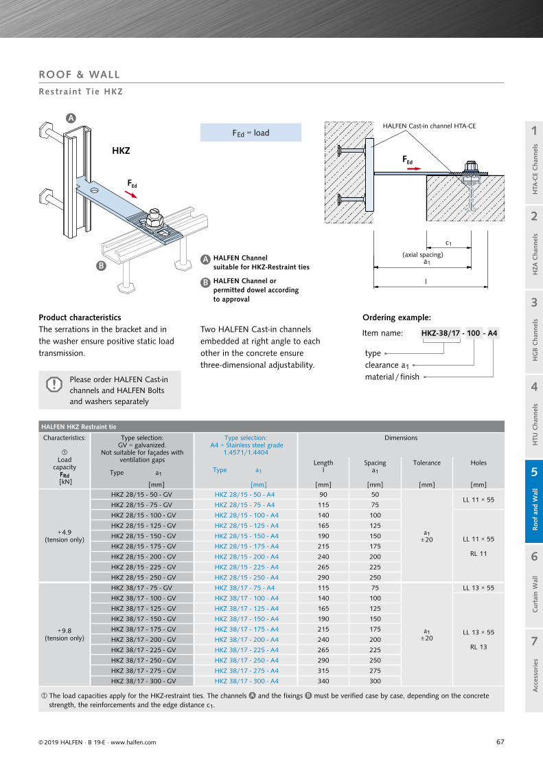
67
HALFEN HKZ Restraint tie
Characteristics:
Load
capacityFRd
[kN]
Type selection: GV = galvanized.
Not suitable for façades with ventilation gaps
Type a1
Type selection: A4 = Stainless steel grade
1.4571/1.4404
Dimensions
Type a1
Lengthl
Spacinga1
Tolerance Holes
[mm] [mm] [mm] [mm] [mm] [mm]
+ 4.9(tension only)
HKZ 28/15 - 50 - GV HKZ 28/15 - 50 - A4 90 50
a1± 20
LL 11 × 55HKZ 28/15 - 75 - GV HKZ 28/15 - 75 - A4 115 75
HKZ 28/15 - 100 - GV HKZ 28/15 - 100 - A4 140 100
LL 11 × 55
RL 11
HKZ 28/15 - 125 - GV HKZ 28/15 - 125 - A4 165 125
HKZ 28/15 - 150 - GV HKZ 28/15 - 150 - A4 190 150
HKZ 28/15 - 175 - GV HKZ 28/15 - 175 - A4 215 175
HKZ 28/15 - 200 - GV HKZ 28/15 - 200 - A4 240 200
HKZ 28/15 - 225 - GV HKZ 28/15 - 225 - A4 265 225
HKZ 28/15 - 250 - GV HKZ 28/15 - 250 - A4 290 250
+ 9.8(tension only)
HKZ 38/17 - 75 - GV HKZ 38/17 - 75 - A4 115 75
a1± 20
LL 13 × 55
HKZ 38/17 - 100 - GV HKZ 38/17 - 100 - A4 140 100
LL 13 × 55
RL 13
HKZ 38/17 - 125 - GV HKZ 38/17 - 125 - A4 165 125
HKZ 38/17 - 150 - GV HKZ 38/17 - 150 - A4 190 150
HKZ 38/17 - 175 - GV HKZ 38/17 - 175 - A4 215 175
HKZ 38/17 - 200 - GV HKZ 38/17 - 200 - A4 240 200
HKZ 38/17 - 225 - GV HKZ 38/17 - 225 - A4 265 225
HKZ 38/17 - 250 - GV HKZ 38/17 - 250 - A4 290 250
HKZ 38/17 - 275 - GV HKZ 38/17 - 275 - A4 315 275
HKZ 38/17 - 300 - GV HKZ 38/17 - 300 - A4 340 300
The load capacities apply for the HKZ-restraint ties. The channels A and the fixings B must be verified case by case, depending on the concrete strength, the reinforcements and the edge distance c1.
FEd
FEd
a1
c1
A
A B
B
© 2019 HALFEN · B 19-E · www.halfen.com
Cur
tain
Wal
lH
TU C
hann
els
Roo
f an
d W
all
HG
B C
hann
els
1
2
5
4
3
7
6
Acc
esso
ries
H
ZA C
hann
els
HTA
-CE
Cha
nnel
s
Product characteristicsThe serrations in the bracket and in the washer ensure positive static load transmission.
HKZ
(axial spacing)
HALFEN Cast-in channel HTA-CE
Item name: HKZ-38/17 - 100 - A4
type clearance a1
material / finishPlease order HALFEN Cast-in channels and HALFEN Bolts and washers separately
ROOF & WALL
Res tra int T ie HKZ
Ordering example:
HALFEN Channel suitable for HKZ-Restraint ties
HALFEN Channel or permitted dowel according to approval
Two HALFEN Cast-in channels embedded at right angle to each other in the concrete ensure three-dimensional adjustability.
FEd = load
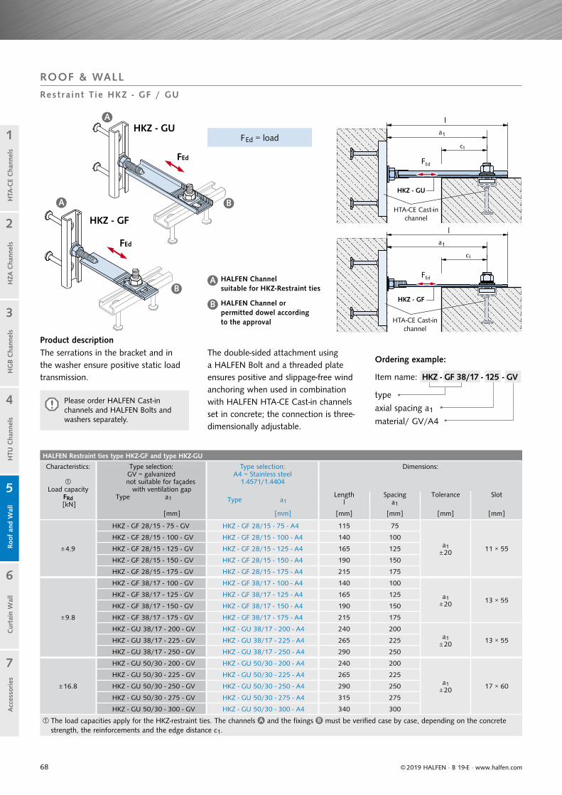
68
FEd = load
FEd
FEd
FEd
l
c1
FEd
l
c1
A
A
A B
B
B
© 2019 HALFEN · B 19-E · www.halfen.com
Cur
tain
Wal
lH
TU C
hann
els
Roo
f an
d W
all
HG
B C
hann
els
1
2
5
4
3
7
6
Acc
esso
ries
H
ZA C
hann
els
HTA
-CE
Cha
nnel
s
Ordering example:
type
axial spacing a1
material/ GV/A4
Item name: HKZ - GF 38/17 - 125 - GV
HKZ - GU
HKZ - GF
The serrations in the bracket and in the washer ensure positive static load transmission.
The double-sided attachment using a HALFEN Bolt and a threaded plate ensures positive and slippage-free wind anchoring when used in combination with HALFEN HTA-CE Cast-in channels set in concrete; the connection is three-dimensionally adjustable.
ROOF & WALL
Res tra int T ie HKZ - GF / GU
Product description
HTA-CE Cast-in channel
HTA-CE Cast-in channel
HALFEN Channel or permitted dowel according to the approval
HALFEN Channel suitable for HKZ-Restraint ties
HALFEN Restraint ties type HKZ-GF and type HKZ-GU
Characteristics:
Load capacity
FRd [kN]
Type selection: GV = galvanized not suitable for façades with ventilation gap
Type a1
Type selection: A4 = Stainless steel
1.4571/1.4404
Dimensions:
Type a1Length
lSpacing
a1
Tolerance Slot
[mm] [mm] [mm] [mm] [mm] [mm]
± 4.9
HKZ - GF 28/15 - 75 - GV HKZ - GF 28/15 - 75 - A4 115 75
a1± 20 11 × 55
HKZ - GF 28/15 - 100 - GV HKZ - GF 28/15 - 100 - A4 140 100
HKZ - GF 28/15 - 125 - GV HKZ - GF 28/15 - 125 - A4 165 125
HKZ - GF 28/15 - 150 - GV HKZ - GF 28/15 - 150 - A4 190 150
HKZ - GF 28/15 - 175 - GV HKZ - GF 28/15 - 175 - A4 215 175
± 9.8
HKZ - GF 38/17 - 100 - GV HKZ - GF 38/17 - 100 - A4 140 100
a1± 20 13 × 55
HKZ - GF 38/17 - 125 - GV HKZ - GF 38/17 - 125 - A4 165 125
HKZ - GF 38/17 - 150 - GV HKZ - GF 38/17 - 150 - A4 190 150
HKZ - GF 38/17 - 175 - GV HKZ - GF 38/17 - 175 - A4 215 175
HKZ - GU 38/17 - 200 - GV HKZ - GU 38/17 - 200 - A4 240 200a1
± 20 13 × 55HKZ - GU 38/17 - 225 - GV HKZ - GU 38/17 - 225 - A4 265 225
HKZ - GU 38/17 - 250 - GV HKZ - GU 38/17 - 250 - A4 290 250
± 16.8
HKZ - GU 50/30 - 200 - GV HKZ - GU 50/30 - 200 - A4 240 200
a1± 20 17 × 60
HKZ - GU 50/30 - 225 - GV HKZ - GU 50/30 - 225 - A4 265 225
HKZ - GU 50/30 - 250 - GV HKZ - GU 50/30 - 250 - A4 290 250
HKZ - GU 50/30 - 275 - GV HKZ - GU 50/30 - 275 - A4 315 275
HKZ - GU 50/30 - 300 - GV HKZ - GU 50/30 - 300 - A4 340 300
The load capacities apply for the HKZ-restraint ties. The channels A and the fixings B must be verified case by case, depending on the concrete strength, the reinforcements and the edge distance c1.
Please order HALFEN Cast-in channels and HALFEN Bolts and washers separately.

69
60
3515
65 140
10 25≥3
010
170
75
Ø 6B500B(BSt 500 S)
FEd
C 30/37
C 30/37
anzuschließendesBetonfertigteil
MontageteilLasche HVL - M
© 2019 HALFEN · B 19-E · www.halfen.com
Cur
tain
Wal
lH
TU C
hann
els
Roo
f an
d W
all
HG
B C
hann
els
1
2
5
4
3
7
6
Acc
esso
ries
H
ZA C
hann
els
HTA
-CE
Cha
nnel
s
Pre-assembled, consisting of:• serrated hammer-head strap• 1 serrated counter plate• 2 bolt sets
(Bolt HS 38/17 - M12 × 50+ washer+ tapered compressed spring)
HALFEN Cast-in channel HTA 38/17-300-SK with 2 bolt anchors and one loop end anchor.
• hammer-head strap, cast-in channel:hot-dip galvanized
• HALFEN Bolts, nuts, washers and springs: galvanized
Assembly:The connecting strap is delivered ready to be installed: The bolt fastening sets and the counter plate are pre-assembled for fast installation.
Installationcomponent 2,cast-in channelHTA-CE 38/17 - 150
Assembly partStrap HVL - M
Precast concrete element
Installationcomponent 1,cast-in channel HVL - E
Pre-assembled components
ROOF & WALL
Precas t Connect ion HVL
Assembly part HVL-M Installation component 1 HVL-E: Corrosion protection
Longitudinal section Cross section
FEd = ± 8.4 kN
These parts are covered by mortar after installation.
Plan view On-site reinforcementLength of recess: 350
HVL-E
Installation component 2:HALFEN Cast-in channel HTA-CE 38/17-150 with 2 bolt anchors.
On-site reinforcement ∅28
Stirrup ∅8
FEd
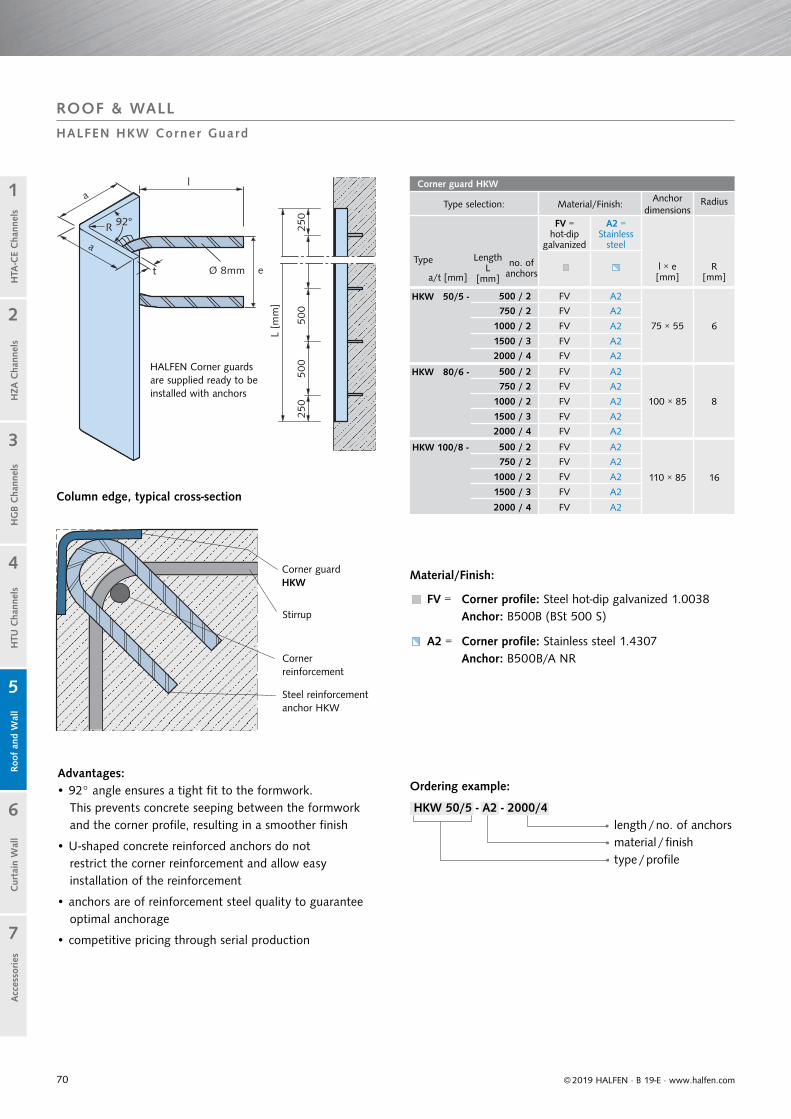
70
Corner guard HKW
Type selection: Material/Finish:Anchor
dimensionsRadius
FV = hot-dip
galvanized
A2 = Stainless
steel
l × e[mm]
R[mm]
Type LengthL
[mm]
no. of anchorsa/t [mm]
HKW 50/5 - 500 / 2 FV A2
75 × 55 6
750 / 2 FV A2
1000 / 2 FV A2
1500 / 3 FV A2
2000 / 4 FV A2
HKW 80/6 - 500 / 2 FV A2
100 × 85 8
750 / 2 FV A2
1000 / 2 FV A2
1500 / 3 FV A2
2000 / 4 FV A2
HKW 100/8 - 500 / 2 FV A2
110 × 85 16
750 / 2 FV A2
1000 / 2 FV A2
1500 / 3 FV A2
2000 / 4 FV A2
a
a
92°R
t e
l
Ø 8mm
250
500
500
250
L[m
m]
Cur
tain
Wal
lH
TU C
hann
els
Roo
f an
d W
all
HG
B C
hann
els
1
2
5
4
3
7
6
Acc
esso
ries
© 2019 HALFEN · B 19-E · www.halfen.com
HZA
Cha
nnel
sH
TA-C
E C
hann
els
HALFEN Corner guards are supplied ready to be installed with anchors
Column edge, typical cross-section
Corner guardHKW
Stirrup
Corner reinforcement
Steel reinforcement anchor HKW
Advantages:• 92° angle ensures a tight fit to the formwork.
This prevents concrete seeping between the formwork and the corner profile, resulting in a smoother finish
• U-shaped concrete reinforced anchors do not restrict the corner reinforcement and allow easy installation of the reinforcement
• anchors are of reinforcement steel quality to guarantee optimal anchorage
• competitive pricing through serial production
Ordering example:
HKW 50/5 - A2 - 2000/4length / no. of anchorsmaterial / finishtype / profile
ROOF & WALL
HALFEN HKW Corner Guard
Material/Finish:
FV = Corner profile: Steel hot-dip galvanized 1.0038 Anchor: B500B (BSt 500 S)
A2 = Corner profile: Stainless steel 1.4307 Anchor: B500B/A NR
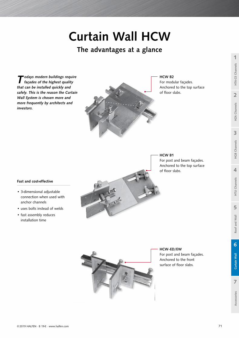
71© 2019 HALFEN · B 19-E · www.halfen.com
Cur
tain
Wal
lH
TU C
hann
els
Roof
and
Wal
lH
TA-C
E C
hann
els
HG
B C
hann
els
1
2
5
4
3
7
6
HZA
Cha
nnel
sA
cces
sories
HCW-ED/EWFor post and beam façades.Anchored to the frontsurface of floor slabs.
T odays modern buildings require façades of the highest quality
that can be installed quickly and safely. This is the reason the Curtain Wall System is chosen more and more frequently by architects and investors.
Fast and cost-effective
• 3-dimensional adjustableconnection when used withanchor channels
• uses bolts instead of welds
• fast assembly reduces installation time
HCW B1For post and beam façades.Anchored to the top surfaceof floor slabs.
Curtain Wall HCWThe advantages at a glance
HCW B2For modular façades.Anchored to the top surfaceof floor slabs.
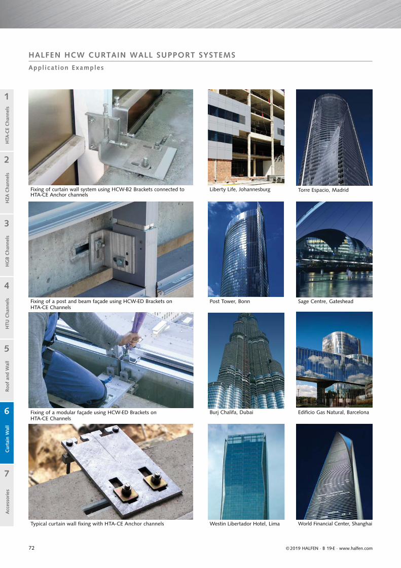
72
Cur
tain
Wal
lH
TU C
hann
els
Roof
and
Wal
lH
TA-C
E C
hann
els
HG
B C
hann
els
1
2
5
4
3
7
6
HZA
Cha
nnel
sA
cces
sories
© 2019 HALFEN · B 19-E · www.halfen.com
Cur
tain
Wal
lH
TU C
hann
els
Roof
and
Wal
lH
TA-C
E C
hann
els
HG
B C
hann
els
1
2
5
4
3
7
6
HZA
Cha
nnel
sA
cces
sories
HALFEN HCW CURTAIN WALL SUPPORT SYSTEMS
Appl icat ion Examples
Fixing of a post and beam façade using HCW-ED Brackets onHTA-CE Channels
Fixing of a modular façade using HCW-ED Brackets on HTA-CE Channels
Fixing of curtain wall system using HCW-B2 Brackets connected to HTA-CE Anchor channels
Liberty Life, Johannesburg
Burj Chalifa, Dubai
Westin Libertador Hotel, LimaTypical curtain wall fi xing with HTA-CE Anchor channels
Sage Centre, GatesheadPost Tower, Bonn
World Financial Center, Shanghai
Torre Espacio, Madrid
Edifi cio Gas Natural, Barcelona
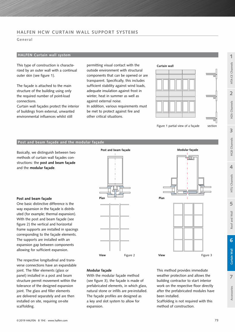
73© 2019 HALFEN · B 19-E · www.halfen.com
Cur
tain
Wal
lH
TU C
hann
els
Roof
and
Wal
lH
TA-C
E C
hann
els
HG
B C
hann
els
1
2
5
4
3
7
6
HZA
Cha
nnel
sA
cces
sories
C
urta
in W
all
HTU
Cha
nnel
sRo
of a
nd W
all
HTA
-CE
Cha
nnel
sH
GB
Cha
nnel
s
1
2
5
4
3
7
6
HZA
Cha
nnel
sA
cces
sories
HALFEN HCW CURTAIN WALL SUPPORT SYSTEMS
Genera l
HALFEN Curtain wall system
This type of construction is characte-rized by an outer wall with a continual outer skin (see figure 1).
The façade is attached to the main structure of the building using only the required number of point-load connections.Curtain wall façades protect the interior of buildings from external, unwantedenvironmental influences whilst still
Basically, we distinguish between two methods of curtain wall façades con-structions: the post and beam façade and the modular façade.
Post and beam façade One basic distinctive difference is the way expansion in the façade is distrib-uted (for example; thermal expansion).With the post and beam façade (see figure 2) the vertical and horizontal frame supports are installed in spacings corresponding to the façade elements. The supports are installed with an expansion gap between components allowing for sufficient expansion.
The respective longitudinal and trans-verse connections have an expandable joint. The filler elements (glass or panel) installed in a post and beam structure permit movement within the tolerance of the designed expansion joint. The glass and filler elements are delivered separately and are then installed on site, requiring on-site scaffolding.
Modular façade With the modular façade method (see figure 3), the façade is made of prefabricated elements, in which glass, natural stone or infills are pre-installed. The façade profiles are designed as a key and slot system to allow for expansion.
This method provides immediate weather protection and allows the building contractor to start interior work on the respective floor directly after the prefabricated modules have been installed. Scaffolding is not required with this method of construction.
permitting visual contact with the outside environment with structural components that can be opened or are transparent. Specifically, this includes sufficient stability against wind loads, adequate insulation against frost in winter, heat in summer as well as against external noise.In addition, various requirements must be met to protect against fire and other critical situations.
Post and beam façade and the modular façade
Figure 2 Figure 3
Figure 1 partial view of a façade section
Plan
View
Plan
View
Curtain wall
Post and beam façade Modular façade
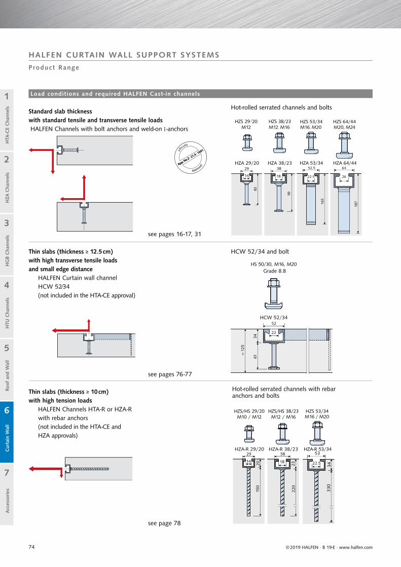
74
83
99
HZA 53/34
HZS 53/34M16, M20M12, M16
165
64HZA 64/44
HZS 64/44M20, M24
187
22.5 26
52.5
53HZA-R 53/34
HZS 53/34M16 / M20
3433
0
22.5
52
3461
22
∝12
5
HCW 52/34
HS 50/30, M16, M20
© 2019 HALFEN · B 19-E · www.halfen.com
Cur
tain
Wal
lH
TU C
hann
els
Roof
and
Wal
lH
TA-C
E C
hann
els
HG
B C
hann
els
1
2
5
4
3
7
6
HZA
Cha
nnel
sA
cces
sories
Load conditions and required HALFEN Cast-in channels
Product Range
Thin slabs (thickness ≥ 12.5 cm) with high transverse tensile loads and small edge distance
HALFEN Curtain wall channel HCW 52⁄34 (not included in the HTA-CE approval)
Thin slabs (thickness ≥ 10 cm)with high tension loads HALFEN Channels HTA-R or HZA-R with rebar anchors (not included in the HTA-CE and HZA approvals)
HCW 52/34 and bolt
Grade 8.8
Hot-rolled serrated channels with rebar anchors and bolts
Hot-rolled serrated channels and bolts
HALFEN CURTAIN WALL SUPPORT SYSTEMS
offi
cially
approvedApp. No Z - 21.4 - 1691
see pages 16-17, 31
see pages 76-77
see page 78
Standard slab thickness with standard tensile and transverse tensile loads HALFEN Channels with bolt anchors and weld-on I-anchors

75
2318
150
30
49
220 33
0
HTA-R 50/30HTA -R 40/22
HS 50/30M12, M16, M20
HTA-R 52/34
HS 40/22M12, M16
39,5
22,5
52,5
33,522,5
39.5
22.5
52.5
33.522.5
162
22
103
50
22
89
40
18
81
38
18
HS 38/17M12, M16
HS 50/30M12, M16, M20
HS 40/22M12, M16
54/3349/3040/2538/17HTA-CE HTA-CE HTA-CE HTA-CE53.5
97
112
162
49
18
72
191
33
HTA-CE 40/22P HTA-CE 50/30P HTA-CE 52/34 HTA-CE 72/4852.539.5
22.5 22.5
17
38
18
150
40
25
18
150
50
30
22
220
54
33
22
330
HS 38/17M12, M16
HS 50/30M12, M16, M20
HS 40/22M12, M16
HTA-R 54/33HTA-R 49/30HTA-R 40/25HTA-R 38/17
© 2019 HALFEN · B 19-E · www.halfen.com
Cur
tain
Wal
lH
TU C
hann
els
Roof
and
Wal
lH
TA-C
E C
hann
els
HG
B C
hann
els
1
2
5
4
3
7
6
HZA
Cha
nnel
sA
cces
sories
Load cases and required HALFEN Channels
Product Range
Cold-rolled (standard) channels and bolts
Hot-rolled (smooth) channels with rebar anchors and bolts
Cold-rolled (smooth) with rebar anchors and bolts
Hot-rolled (standard) channels and bolts
HALFEN CURTAIN WALL SUPPORT SYSTEMS
HCW 52/34 with bolts and bracket
HSR Bolt according to expert reports
EuropeanTechnicalApprovalETA - 09/0339

76
30
© 2019 HALFEN · B 19-E · www.halfen.com
Cur
tain
Wal
lH
TU C
hann
els
Roof
and
Wal
lH
TA-C
E C
hann
els
HG
B C
hann
els
1
2
5
4
3
7
6
HZA
Cha
nnel
sA
cces
sories
Typical installation Product description
Channel dimensions and edge spacingReinforcement requirements
HALFEN Bolt grade 8.8HS 50/30
Dimensions in [mm]Modifications possible
9 b
ars,
dia
met
er 8
mm
at
100 m
m c
entr
es
3 bars, diameter 8 mm,spaced at 100 mm
Curtain wall mullion
Bracket (example)
HALFEN Curtain wall channel HCW 52/34
Concrete slabHALFEN BoltGrade 8.8 (Order separately)
Identification: HCW 52/34Material: hot-dip galvanized
Dimensions in [mm]
HALFEN CURTAIN WALL SUPPORT SYSTEMS
HALFEN Channel HCW 52/34
Note: HALFEN Channel HCW 52/34 is not included in the HTA-CE/HZA Approval.
0.5 FRes.
0.5 FRes.

77
Type selection HALFEN Bolts HS 50/30 GV Grade 8.8
Thread Material grade
Available lengthL
[mm]
Allowable resulting bolt load
(all directions)perm. Fs [kN]
Allowablebending moment
[Nm]
Recommended torque
[Nm] If the bolt is stressed in the direction of a slot its load capacity must be verified taking bolt flexure into account.M 16 8.8 40, 60, 80, 100 36.1 111 60
M 20 8.8 45, 60, 80, 100 56.4 216 120
150
140
130
120
110
100
90
80
70
60
50
40
30
20
10
0
1 2 3 4 5 6 7
[kN]
36.4
γ 1=
4.12
0.5 Fres
0.5 Fres
© 2019 HALFEN · B 19-E · www.halfen.com
Cur
tain
Wal
lH
TU C
hann
els
Roof
and
Wal
lH
TA-C
E C
hann
els
HG
B C
hann
els
1
2
5
4
3
7
6
HZA
Cha
nnel
sA
cces
sories
HALFEN Cas t - in Channel HCW 52/34
Channel load data
Depending on the load size, we recommend the use of HALFEN Bolts HS 50/30 M16 or M20, grade 8.8 in combi-nation with HALFEN Cast-in channel HCW 52/34. The bolts stated below are zinc galvanized with a special coating.
For interior use this design is considered equivalent to a hot-dip galvanized design. Other bolt sizes and materials can be supplied. Please contact us for detailed information. Addresses can be found on page 91.
Displacement r [mm] in load direction Fres
The safety factor is freely selected. However, it must be determined which factors are actually to be implemented, whether these are based on project specifi c boundary condition or on valid building regulations.
Fres, ultimate = 150 kN
Load deformation diagram
Load Fres.
1st indication of crack in the concrete
The following load failure were averaged from three tests:
Calculation example: Assumed safety factor ν = 3 (failure test load / working load)
The load deformation diagram (see right) may be used to determine allowable loads based on acceptable displacement and the required safety factor according to local building codes. The diagram is based on the following:• tensile and transverse loads were increased at a ratio of 1:3 up to
breaking point• concrete slab thickness ≥ 125 mm and reinforcement as shown on
page 76• concrete strength class ≥ C 20/25 N/mm²• load is transferred into the channel via two HALFEN Bolts HS
50/30 M20 Grade 8.8. The bolt spacing is 150 mm. A sample calculation is shown below.
Average failure load from the tests:Transverse tensile stress FV ultimate = 142.3 kNTensile stress FN ultimate = 47.4 kNRes. diagonal tensile load Fres,ultimate = 150.0 kN
Actual working loads at bolts (specification by façade stress engineer): Transverse tensile stress FV = 35 kN Tensile stress FN = 10 kN
Allowable load with ν = 3 against average ultimate load from tests: perm. FV = 142.3 / 3 = 47.4 kN perm. FN = 47.4 / 3 = 15.8 kN perm. Fres = 150 / 3 = 50.0 kN
Control: Working load FV = 35 kN < 47.4 kN Working load FN = 10 kN < 15.8 kN Working load Fres = = 36.4 kN < 50 kN
Displacement at working load < 1 mm (see diagram).Actual safety factor for average ultimate load 1 = (150 / 36.4) = 4.12.
FV failure = 142.3 kN
FN failure = 47.4 kN
Fres,failure = = 150.0 kN
HALFEN CURTAIN WALL SUPPORT SYSTEMS
Corresponding HALFEN Bolts HS 50/30

78
HALFEN Cast-in channel type HTA-R 38/17 HTA-R 40/25 HTA-R 40/22 HZA-R 29/20
HTA-R 49/30 HTA-R 50/30 HZA-R 38/23
HTA-R 54/33 HTA-R 52/34 HZA-R 53/34
350 mm3 anchors
350 mm3 anchors
350 mm3 anchors
350 mm3 anchors
Concrete strength grade≥ C20/25
fck,cyl. = 20 N/mm²fck,cube = 25 N/mm²
FRd = NRd [kN] 2 × 7.0 2 × 9.1 2 × 14.0 2 × 24.5
ar [mm] ae [mm] VyRd [kN]
≥ 50 ≥ 40 2 × 2.4
≥ 60 ≥ 45 2 × 3.7
≥ 70 ≥ 50 2 × 4.9
≥ 75 ≥ 50 2 × 5.6
Material:hot-dip
galvanized
Channel 1.0038 , 1.0044
Anchor B500B (BSt 500S)
Material:stainless steel
Channel 1.4571 / 1.4404
Anchor B500B (BSt 500S)
Material 1.0038, Material 1.0044 , Not available for HALFEN Cast-in channels HZA-R 29/20Notes: HALFEN Cast-in channels HTA-R / HZA-R are not included in the HTA-CE / HZA Approval Other channel lengths from 150 – 6070 mm are available
23
39.539,5
FF FF FF FF
150
17
38
12
4025
29
2015
0
12
49
3030
49
3823
220
12
54
33
© 2019 HALFEN · B 19-E · www.halfen.com
Cur
tain
Wal
lH
TU C
hann
els
Roof
and
Wal
lH
TA-C
E C
hann
els
HG
B C
hann
els
1
2
5
4
3
7
6
HZA
Cha
nnel
sA
cces
sories
C
urta
in W
all
HTU
Cha
nnel
sRo
of a
nd W
all
HTA
-CE
Cha
nnel
sH
GB
Cha
nnel
s
1
2
5
4
3
7
6
HZA
Cha
nnel
sA
cces
sories
HALFEN Cast - in Channels wi th Rebar Anchor HTA-R and HZA-R
HALFEN CURTAIN WALL SUPPORT SYSTEMS
Design bas ics
HALFEN Channels HTA-R and HZA-R — Design values for material resistance
Structural analysis
The minimum edge distance shown in the tableapplies to reinforced concrete
Shear VyEdTension NEdres. Tension FEd
39.5
Material resistance Design load
Material resistance shear VyRd ≥ VyEdMaterial resistance tension NRd ≥ NEdMaterial resistance FRd ≥ FEd = resulting diagonal pull
34
52.552.5
14 330
33.5
52.5

79
Bracket dimensions [mm]
HCW-ED Bracketsfor dead loadsand wind loads
HCW-EW Bracketswind loads only
Serrated washers included in delivery Serrated washers included in delivery
Size Bracket code A B C D E F G H J L M
Small HCW-ED 1HCW-EW 1 108 70 114 10 57 64 25 51 36 40 57
Medium HCW-ED 2HCW-EW 2 133 70 127 10 64 64 51 51 36 40 82
Large HCW-ED 3HCW-EW 3 159 70 140 10 70 64 76 51 36 40 108
J
p
MFhd2
±
Fvd2
c1,1
c1,2
© 2019 HALFEN · B 19-E · www.halfen.com
Cur
tain
Wal
lH
TU C
hann
els
Roof
and
Wal
lH
TA-C
E C
hann
els
HG
B C
hann
els
1
2
5
4
3
7
6
HZA
Cha
nnel
sA
cces
sories
C
urta
in W
all
HTU
Cha
nnel
sRo
of a
nd W
all
HTA
-CE
Cha
nnel
sH
GB
Cha
nnel
s
1
2
5
4
3
7
6
HZA
Cha
nnel
sA
cces
sories
HALFEN CURTAIN WALL SUPPORT SYSTEMS
Edge of S lab Brackets HCW-ED Post and Beam Façades
Application example
HALFEN Edge of slab brackets are connected in pairs, one each side of the mullion, and are available in two types:
• Type HCW-ED Brackets are designed to support both vertical and horizontal loads.
• Type HCW-EW Brackets are designed to supporthorizontal wind loads only.
The brackets guarantee a simple adjustable connection.The HALFEN Bolts (connection: bracket to HALFEN Channel) and the standard hexagonal bolts M12 (connection: bracket to façade mullion) must be grade strength 8.8. A round auxiliary hole in the long arm of the brackets can be used for temporary attachments; example: temporary fixing of brackets to support the post with self-tapping screws until the final connection is made.
The brackets are made of high quality aluminium material.Special nylon discs are placed between the “Wind load” Bracket HCW-EW and support post.
bolt spacing
To guarantee correct installation, the HCW-ED brackets are marked ‘R’ for right, ‘L’ for left and ‘UP’ for top.

80
-25 2520-20 -15 15-10 10-5 0 5
-25 2520-20 -15 15-10 10-5 0 5
Fvd2
Fvd2
Fhd2
Fhd2
+−+−
c1,2
c1,1
-25 2520-20 -15 15-10 10-5 0 5
x
7.0
3.5
6.86.8
7.08
6.92 6.92
7.08
6.8-6.8
-7.08
-6.92
-13.96 13.96
6.92
7.577.577.577.577.577.577.577.577.577.577.577.577.577.577.577.577.577.577.577.577.577.577.577.577.577.577.57
7.08
11.67-11.67
7.87
8.27
8.5-8.5
© 2019 HALFEN · B 19-E · www.halfen.com
Cur
tain
Wal
lH
TU C
hann
els
Roof
and
Wal
lH
TA-C
E C
hann
els
HG
B C
hann
els
1
2
5
4
3
7
6
HZA
Cha
nnel
sA
cces
sories
HALFEN CURTAIN WALL SUPPORT SYSTEMS
Interaction diagram for type HCW-ED1 (small)
Interaction diagram for type HCW-ED2 (medium)
Interaction diagram for type HCW-ED3 (large)
Defi nition of loads at bracket / post connection
Design value of the horizontal acting load Fhd [kN]
Design value of the horizontal acting load Fhd [kN]
Design value of the horizontal acting load Fhd [kN]
Des
ign
valu
e of
the
ver
tical
act
ing
load
[kN
]D
esig
n va
lue
of t
he v
ertic
al a
ctin
g lo
ad F
vd [
kN]
Des
ign
valu
e of
the
ver
tical
act
ing
load
Fvd
[kN
]
required connecting bolt M12 Grade 8.8
required connecting bolt M12 Grade 8.8
required connecting bolt M12 Grade 8.8
Permitted load interaction area
7.0
3.5
Dimensioning
Calculation basis
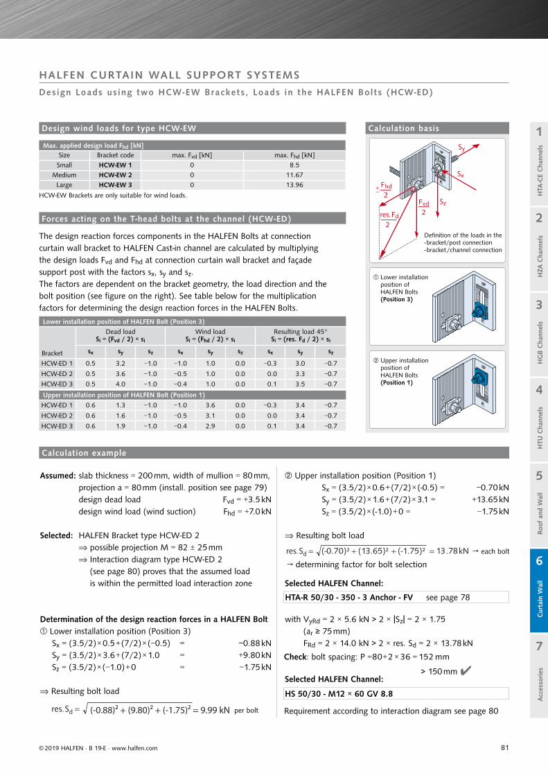
81
Max. applied design load Fhd [kN]Size Bracket code max. Fvd [kN] max. Fhd [kN]
Small HCW-EW 1 0 8.5
Medium HCW-EW 2 0 11.67
Large HCW-EW 3 0 13.96
HCW-EW Brackets are only suitable for wind loads.
Lower installation position of HALFEN Bolt (Position 3)
Bracket
Dead loadSi = (Fvd / 2) × si
Wind loadSi = (Fhd / 2) × si
Resulting load 45°Si = (res. Fd / 2) × si
sx sy sz sx sy sz sx sy sz
HCW-ED 1 0.5 3.2 −1.0 −1.0 1.0 0.0 −0.3 3.0 −0.7
HCW-ED 2 0.5 3.6 −1.0 −0.5 1.0 0.0 0.0 3.3 −0.7
HCW-ED 3 0.5 4.0 −1.0 −0.4 1.0 0.0 0.1 3.5 −0.7
Upper installation position of HALFEN Bolt (Position 1)
HCW-ED 1 0.6 1.3 −1.0 −1.0 3.6 0.0 −0.3 3.4 −0.7
HCW-ED 2 0.6 1.6 −1.0 −0.5 3.1 0.0 0.0 3.4 −0.7
HCW-ED 3 0.6 1.9 −1.0 −0.4 2.9 0.0 0.1 3.4 −0.7
Sy
Sx
SzFvd2res.Fd
2
Fhd2
+−
© 2019 HALFEN · B 19-E · www.halfen.com
Cur
tain
Wal
lH
TU C
hann
els
Roof
and
Wal
lH
TA-C
E C
hann
els
HG
B C
hann
els
1
2
5
4
3
7
6
HZA
Cha
nnel
sA
cces
sories
HALFEN CURTAIN WALL SUPPORT SYSTEMS
Design Loads us ing two HCW-EW Brackets , Loads in the HALFEN Bol ts (HCW-ED)
Calculation basisDesign wind loads for type HCW-EW
The design reaction forces components in the HALFEN Bolts at connection curtain wall bracket to HALFEN Cast-in channel are calculated by multiplying the design loads Fvd and Fhd at connection curtain wall bracket and façade support post with the factors sx, sy and sz. The factors are dependent on the bracket geometry, the load direction and the bolt position (see figure on the right). See table below for the multiplication factors for determining the design reaction forces in the HALFEN Bolts.
Defi nition of the loads in the - bracket/post connection- bracket /channel connection
Lower installation position of HALFEN Bolts(Position 3)
Assumed: slab thickness = 200 mm, width of mullion = 80 mm, projection a = 80 mm (install. position see page 79)
design dead load Fvd = +3.5 kN design wind load (wind suction) Fhd = +7.0 kN
Selected: HALFEN Bracket type HCW-ED 2 possible projection M = 82 ± 25 mm
Interaction diagram type HCW-ED 2 (see page 80) proves that the assumed load is within the permitted load interaction zone
Determination of the design reaction forces in a HALFEN Bolt Lower installation position (Position 3)
Sx = (3.5/2) × 0.5 + (7/2) × (−0.5) = −0.88 kNSy = (3.5/2) × 3.6 + (7/2) × 1.0 = +9.80 kNSz = (3.5/2) × (−1.0) + 0 = −1.75 kN
Resulting bolt load
(-0.88)2 + (9.80)2 + (-1.75)2 = 9.99 kN
Upper installation position of HALFEN Bolts(Position 1)
Forces acting on the T-head bolts at the channel (HCW-ED)
Upper installation position (Position 1) Sx = (3.5/2) × 0.6 + (7/2) × (-0.5) = −0.70 kN Sy = (3.5/2) × 1.6 + (7/2) × 3.1 = +13.65 kN Sz = (3.5/2) × (-1.0) + 0 = −1.75 kN
Resulting bolt load
Selected HALFEN Channel:
with VyRd = 2 × 5.6 kN > 2 × Sz = 2 × 1.75 (ar ≥ 75 mm)
FRd = 2 × 14.0 kN > 2 × res. Sd = 2 × 13.78 kN
Selected HALFEN Channel:
Calculation example
HTA-R 50/30 - 350 - 3 Anchor - FV see page 78
HS 50/30 - M12 × 60 GV 8.8
→ each bolt
per bolt
→ determining factor for bolt selection
Check: bolt spacing: P =80+2 × 36 = 152 mm
Requirement according to interaction diagram see page 80
> 150 mm

82
Design load ranges
Load range[kN]
dead load Fvd[kN]
wind load Fhd [kN](wind suction + compression)
4/12 4 ±12
7/20 7 ±20
Fvd , Fhd : allowable design loads with a partial safety factor F = 1.35 for dead load and F = 1.5 for wind load.
Type selection
Load range[kN]
a[mm]
Item nameHCW-B1 -...
L[mm]
W[mm]
HALFENChannel
Recommended HALFEN Bolt
4/12
50 ...- 4/12-50 270 150HTA-CE
40/22P-2502 Anchors
HS 40/22M16×60
8.875 ...- 4/12-75 295 150
100 ... - 4/12-100 320 150
7/20
50 ...- 7/20 -50 270 175HTA-CE
50/30P-3003 Anchors
HS 50/30M16×60
8.875 ...- 7/20 -75 295 175
100 ...- 7/20 -100 320 200
Recommended HALFEN Channel exploiting full load capacity of bracket
ds = 12 200
© 2019 HALFEN · B 19-E · www.halfen.com
Cur
tain
Wal
lH
TU C
hann
els
Roof
and
Wal
lH
TA-C
E C
hann
els
HG
B C
hann
els
1
2
5
4
3
7
6
HZA
Cha
nnel
sA
cces
sories
HALFEN CURTAIN WALL SUPPORT SYSTEMS
Top of S lab Brackets HCW-B1
Support brackets for horizontal and vertical loads
Typical installation
Curtain wall post;post and beam façade
Concrete slab
HCW-B1
HALFEN Cast-in channel
HALFEN Brackets HCW-B1 HALFEN Brackets HCW-B1 for installing to the top of concrete slabs, are available in two load ranges and three cantilever sizes. The brackets are made in grade S355 quality galvanized steel. Vertical adjustability is ±10 mm. Three dimensional adjustability is ensured when used in combination with HALFEN HTA-CE Cast-in channels.
The lateral connecting plates are connected to the façade posts using M8 screws (not included). The façade planner is responsible for providing the static verification for the support posts. Use M16 HALFEN Bolts, grade 8.8 (order separately), to connect the base bracket to the HALFEN Cast-in channel. Depending on the façade type, the connection between the connecting plate and the base bracket can be designed either laterally adjustable or as a fixed point.
Dimensioning / Type selection
Section
Plan
Required edge reinforcement ≥ ∅12 (B500B)
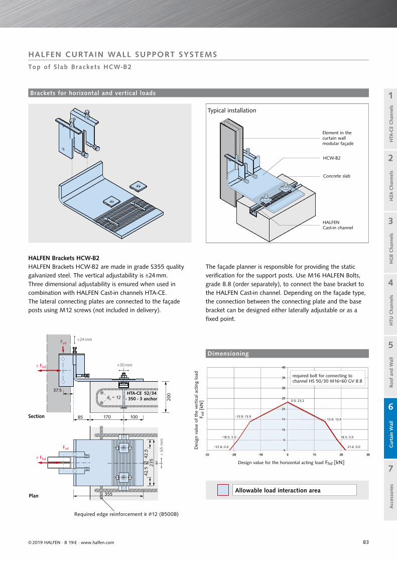
83
HTA-CEds = 12 20
0
anchor 0.0; 23.2
13.9; 13.9−13.9; 13.9
18.5; 5.0−18.5; 5.0
21.6; 0.0−21.6; 0.0
© 2019 HALFEN · B 19-E · www.halfen.com
Cur
tain
Wal
lH
TU C
hann
els
Roof
and
Wal
lH
TA-C
E C
hann
els
HG
B C
hann
els
1
2
5
4
3
7
6
HZA
Cha
nnel
sA
cces
sories
HALFEN CURTAIN WALL SUPPORT SYSTEMS
Top of S lab Brackets HCW-B2
Brackets for horizontal and vertical loads
Element in thecurtain wall modular façade
Concrete slab
HALFEN Cast-in channel
Typical installation
HALFEN Brackets HCW-B2 HALFEN Brackets HCW-B2 are made in grade S355 quality galvanized steel. The vertical adjustability is ±24 mm. Three dimensional adjustability is ensured when used in combination with HALFEN Cast-in channels HTA-CE.The lateral connecting plates are connected to the façade posts using M12 screws (not included in delivery).
Design value for the horizontal acting load Fhd [kN]
Des
ign
valu
e of
the
ver
tical
act
ing
load
Fvd
[kN
]
required bolt for connecting to channel HS 50/30 M16×60 GV 8.8
Allowable load interaction area
The façade planner is responsible for providing the static verification for the support posts. Use M16 HALFEN Bolts, grade 8.8 (order separately), to connect the base bracket to the HALFEN Cast-in channel. Depending on the façade type, the connection between the connecting plate and the base bracket can be designed either laterally adjustable or as a fixed point.
Section
Plan
Dimensioning
HCW-B2
Required edge reinforcement ≥ ∅12 (B500B)

84
The whole range of framing system products can be found at www.halfen.de MT-FBC (Flexible bolt connections) or MT-FFC (Flexible framing connections).
© 2019 HALFEN · B 19-E · www.halfen.com
Cur
tain
Wal
lH
TU C
hann
els
Roof
and
Wal
lH
TA-C
E C
hann
els
HG
B C
hann
els
1
2
5
4
3
7
6
HZA
Cha
nnel
sA
cces
sories
KLP ClampThe clamp allows fast connectionof framing channels to I-beams.
T o complement the product range HALFEN off ers a wide
range of accessories. Everything from one source.
HALFEN Framing channelsYou are guaranteed to find an economical solution for your projects in the extensive HALFEN Framing channels product range.
HJV Adjustable couplerAllows free height adjustment in suspended installations.
AccessoriesThe advantages at a glance
HALFEN Adjustable coupler
HALFEN Clamp
The product range
Everything you need from theframing channel right down to the nut, the locking washer, threaded rod, locking and threaded plate even an adjustable connector; we provide all you need for your project.
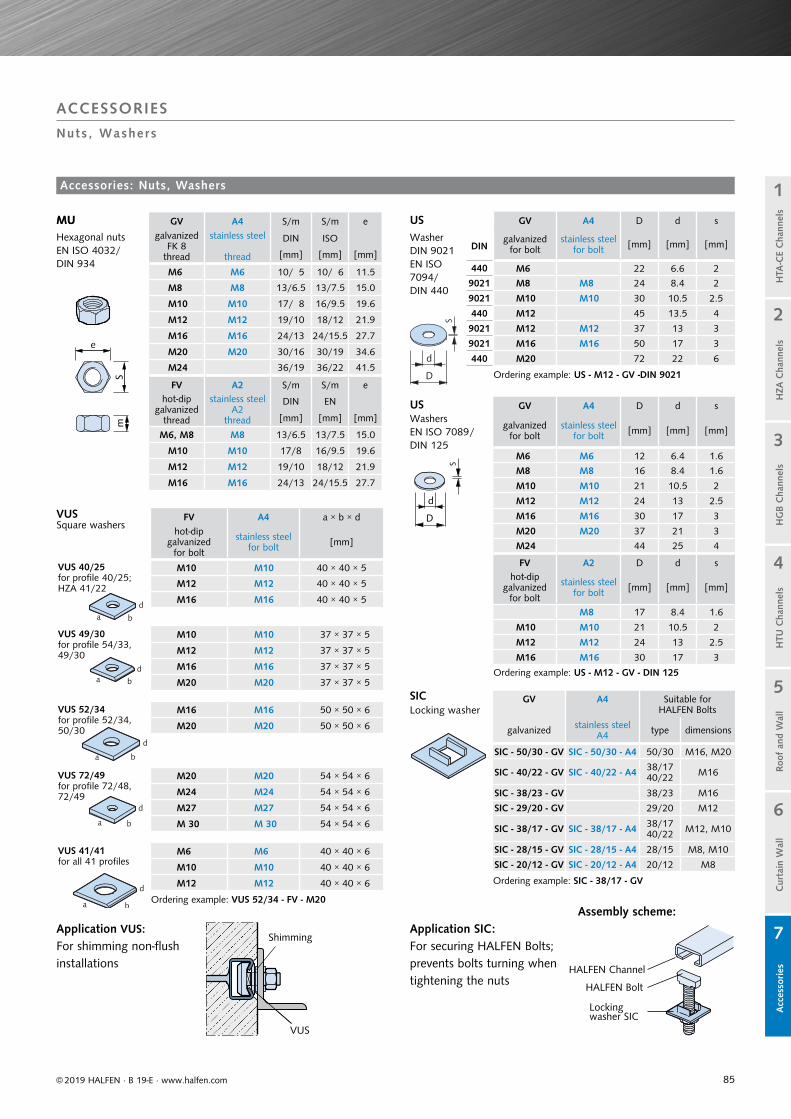
85
GV A4 Suitable for HALFEN Bolts
galvanized stainless steelA4 type dimensions
SIC - 50/30 - GV SIC - 50/30 - A4 50/30 M16, M20
SIC - 40/22 - GV SIC - 40/22 - A4 38/1740/22 M16
SIC - 38/23 - GV 38/23 M16
SIC - 29/20 - GV 29/20 M12
SIC - 38/17 - GV SIC - 38/17 - A4 38/1740/22 M12, M10
SIC - 28/15 - GV SIC - 28/15 - A4 28/15 M8, M10
SIC - 20/12 - GV SIC - 20/12 - A4 20/12 M8
Ordering example: SIC - 38/17 - GV
GV A4 S/m S/m egalvanized
FK 8thread
stainless steel
thread
DIN ISO
[mm] [mm] [mm]
M6 M6 10/ 5 10/ 6 11.5
M8 M8 13/6.5 13/7.5 15.0
M10 M10 17/ 8 16/9.5 19.6
M12 M12 19/10 18/12 21.9
M16 M16 24/13 24/15.5 27.7
M20 M20 30/16 30/19 34.6
M24 36/19 36/22 41.5
FV A2 S/m S/m ehot-dip
galvanized thread
stainless steel A2
thread
DIN EN
[mm] [mm] [mm]
M6, M8 M8 13/6.5 13/7.5 15.0
M10 M10 17/8 16/9.5 19.6
M12 M12 19/10 18/12 21.9
M16 M16 24/13 24/15.5 27.7
DIN
GV A4 D d s
galvanizedfor bolt
stainless steelfor bolt [mm] [mm] [mm]
440 M6 22 6.6 2
9021 M8 M8 24 8.4 2
9021 M10 M10 30 10.5 2.5
440 M12 45 13.5 4
9021 M12 M12 37 13 3
9021 M16 M16 50 17 3
440 M20 72 22 6
Ordering example: US - M12 - GV -DIN 9021
GV A4 D d s
galvanizedfor bolt
stainless steel for bolt [mm] [mm] [mm]
M6 M6 12 6.4 1.6
M8 M8 16 8.4 1.6
M10 M10 21 10.5 2
M12 M12 24 13 2.5
M16 M16 30 17 3
M20 M20 37 21 3
M24 44 25 4
FV A2 D d shot-dip
galvanized for bolt
stainless steel for bolt [mm] [mm] [mm]
M8 17 8.4 1.6
M10 M10 21 10.5 2
M12 M12 24 13 2.5
M16 M16 30 17 3
Ordering example: US - M12 - GV - DIN 125
FV A4 a × b × dhot-dip
galvanized for bolt
stainless steelfor bolt [mm]
VUS 40/25 for profile 40/25;HZA 41/22
M10 M10 40 × 40 × 5
M12 M12 40 × 40 × 5
M16 M16 40 × 40 × 5
VUS 49/30 for profile 54/33,49/30
M10 M10 37 × 37 × 5
M12 M12 37 × 37 × 5
M16 M16 37 × 37 × 5
M20 M20 37 × 37 × 5
VUS 52/34 for profile 52/34, 50/30
M16 M16 50 × 50 × 6
M20 M20 50 × 50 × 6
VUS 72/49 for profile 72/48,72/49
M20 M20 54 × 54 × 6
M24 M24 54 × 54 × 6
M27 M27 54 × 54 × 6
M 30 M 30 54 × 54 × 6
VUS 41/41for all 41 profiles
M6 M6 40 × 40 × 6
M10 M10 40 × 40 × 6
M12 M12 40 × 40 × 6
Ordering example: VUS 52/34 - FV - M20
VUSSquare washers
SICLocking washer
Application SIC:For securing HALFEN Bolts; prevents bolts turning when tightening the nuts
MUHexagonal nutsEN ISO 4032/DIN 934
USWasher DIN 9021 EN ISO 7094/DIN 440
USWashersEN ISO 7089/DIN 125
Application VUS:For shimming non-flush installations
Shimming
Assembly scheme:
Zubehör: Muttern, Unterlegscheiben
VUS
© 2019 HALFEN · B 19-E · www.halfen.com
Cur
tain
Wal
lH
TU C
hann
els
Roof
and
Wal
lH
TA-C
E C
hann
els
HG
B C
hann
els
1
2
5
4
3
7
6
HZA
Cha
nnel
sA
cces
sories
HALFEN Channel
HALFEN Bolt
Locking washer SIC
ACCESSORIES
Nuts , Washers
Accessories: Nuts, Washers
MU

86
GV A4 D L FRd perm. F
hot-dip galvanized
thread
stainless steel
thread [mm]
[mm]
[kN] [kN]
M6 M6 10/10 15 3.1 2.2
M8 M8 12/14 20 5.6 4.0
M10 M10 13/16 25 9.0 6.4
M12 M12 16/20 30 13.0 9.3
M16 M16 21/25 40 24.2 17.3
M20 M20 26/32 50 37.8 27.0
Ordering example: VBM - A4 - M16
FV A4 S L FRd perm. F
hot-dip galvanized
thread
stainless steel
thread [mm]
[mm]
[kN] [kN]
M10 M10 13 40 9.0 6.4
M12 M12 17 40 13.0 9.3
M16 M16 22 50 24.2 17.3
Ordering example: SKM - FV - M12
GV d FRd perm. F
C 15E, galvanized thread
[mm]
[kN] [kN]
M8 20 2.0 1.4
M10 25 3.2 2.3
M12 30 4.8 3.4
M16 35 9.8 7.0
M20 40 16.8 12.0
Ordering example: RM - GV - M12
GV A4 Length FRd perm. F
galvanizedFK 4.6thread
stainless steel
thread [mm]
[kN] [kN]
M6 M6 1000 3.1 2.2
M8 M8 1000 5.6 4.0
M10 M10 1000 9.0 6.4
M12 M12 1000 13.0 9.3
M16 M16 1000 24.2 17.3
M20 M20 1000 37.8 27.0
M24 1000 54.3 38.8
Ordering example: GWS - M12 × 1000 - GV
GV 8.8 A4 S Sgalvanized
FK 8.8dimensions
stainless steel
thread
DIN EN ISO
[mm] [mm]
M6 × 12 10 10
M6 × 25
M8 × 25 M8 × 2513 13
M8 × 40
M10 × 20
17 16
M10 × 30 M10 × 30
M10 × 45 M10 × 45
M10 × 60
M10 × 70
M12 × 22
19 18
M12 × 25 M12 × 25
M12 × 30 M12 × 30
M12 × 40 M12 × 40
M12 × 50
M12 × 60 M12 × 60
M12 × 80 M12 × 80
M12 × 90
M16 × 40 M16 × 40
24 24M16 × 60 M16 × 60
M16 × 90 M16 × 90
FV A4 t b d max. FEd perm. F
hot-dip galvanized
type
stainless steeltype
[mm] [mm] [mm] [kN] [kN]
1 1 6 40 13 2.1 1.5
2 2 8 50 17 4.6 3.3
3 3 10 50 17 7.0 5
A4 A4 D D
stainless steelthread M12
× length L [mm]
stainless steelthread M16
× length L [mm]
forM12[mm]
forM16[mm]
M12 × 60 M16 × 60 16 22
M12 × 75 M16 × 75 16 22
M12 × 95 M16 × 95 16 22
M12 × 115 M16 × 115 16 22
M12 × 135 M16 × 135 16 22
perm. F = 5 kN FRd = 7 kN
perm. F = 10 kN FRd = 14 kN
Ordering example: SPH - A4 - M 12 × 75
© 2019 HALFEN · B 19-E · www.halfen.com
Cur
tain
Wal
lH
TU C
hann
els
Roof
and
Wal
lH
TA-C
E C
hann
els
HG
B C
hann
els
1
2
5
4
3
7
6
HZA
Cha
nnel
sA
cces
sories
VBMCoupler sleeves, round
SKMHexagonal coupler sleeves with view holes
RM
Ring nutDIN 582 edition 2010-09
GWSThreaded rodsDIN 976-1
HSKHexagonal head boltsEN ISO 4017/DIN 933(without nut)
Hex bolts are used in combination with HALFEN Threaded plates
HJVAdjustment coupler
SPHTurnbuckle with right- and left-hand thread
ACCESSORIES
Threaded Rods, Hex Bolts, Coupler Sleeves, Ring Nuts
f = minimum screw depth:
M12 = 10 mmM16 = 13 mm
Recommended design value of the load capacity with a centric tensile stress
Recommended design value of the load Cross section
Accessories: Threaded Rods, Hex Bolts, Coupler Sleeves, Ring Nuts

87
FVhot-dip
galvanized
Heel widthn
for HALFEN Bolts
Dimensions[mm]
allowable load preferred for use with
at σ allowable = 125 N/mm²
Standard profile I
other beam, flange thick-ness channels
channels
Type [mm] Ø × l [mm] a b c Ø d h k m F [kN] t [mm]No. 10 16 M16 × 60 44.0 45 12 18 5 12.0 22.0 3.5 80 – 140 4 – 6 S24No. 26 without heel M16 × 60 62.5 64 21 18 9 16.5 34.5 3.5 160 – 240 7 – 9 S24, A45, A55No. 20 20 M20 × 65 52.0 55 19 □ 21 8 15.0 24.0 10.0 160 – 240 7 – 9 S24 – S49
Ordering example: KLP - S - Nr. 26 - FV □ = square opening
FV Hot-dip
galvanized
Clamping heighth [mm]
Allowable load Preferred for use with
[kN] Standard profile I Standard profile IPB Crane and running tracks
60/10 10 F1 = 7.0 HALFEN Bolt
M16 × 60, Grade 4.6
120 – 160 100 A65, S33, S4160/12 12 220 – 240 140 A100, S49, A7560/14 14 240 – 280 160 – 180 A120, S5460/16 16 F2 = 11.25
HALFEN BoltM16 × 60, Grade 8.8
300 – 340 200 – 220 S6460/18 18 360 – 380 240 – 260 ‒60/20 20 400 – 450 280 – 300 ‒
Take the load capacity of HALFEN Channels into account (Cantilever must be considered when selecting the HALFEN Channels and Bolts) Bolt M16 × 80 necessary Check flange thickness of profile! Order example: KLP - 60/10 - FV
LL 24 x 18
75
18
60
F1 F2
b
n
a
Ø d
F
© 2019 HALFEN · B 19-E · www.halfen.com
Cur
tain
Wal
lH
TU C
hann
els
Roof
and
Wal
lH
TA-C
E C
hann
els
HG
B C
hann
els
1
2
5
4
3
7
6
HZA
Cha
nnel
sA
cces
sories
HALFEN BoltHS 50/30
WasherUS DIN 125
HALFEN Rail clipKLP
HALFEN Framing channelHL 50/40
HALFEN Channel nutwith GWP 50/40
Threaded rod with locking nut and square washer VUS
HALFEN Channel
heel
Load diagram: KLP-S
Assembly exampleKLP-S
The heel engages in the channel slot, securing the rail clip against torsion.
Load diagram KLP - 60
HALFEN Framing channel
Assembly exampleKLP - 60
e.g. HL 50/40
ACCESSORIES
Rail Clips
KLP - S Rail clips, steel 1.0038 forged
KLP - 60 rail clips
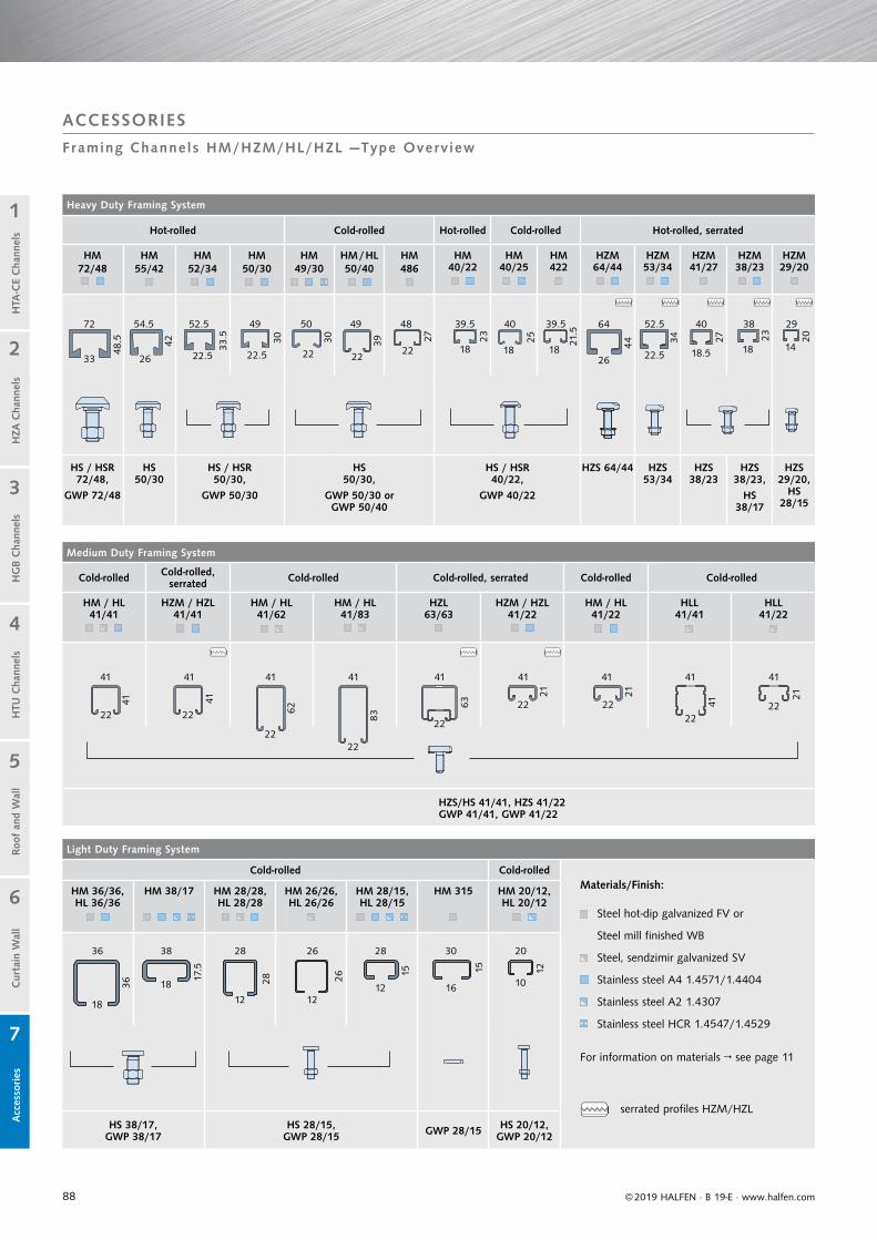
88
Light Duty Framing System
Cold-rolled Cold-rolled
HM 36/36, HL 36/36
HM 38/17 HM 28/28, HL 28/28
HM 26/26, HL 26/26
HM 28/15, HL 28/15
HM 315 HM 20/12, HL 20/12
HS 38/17,GWP 38/17
HS 28/15,GWP 28/15 GWP 28/15 HS 20/12,
GWP 20/12
For information on materials → see page 11
Materials/Finish:
serrated profiles HZM/HZL
Steel hot-dip galvanized FV or
Steel mill finished WB
Steel, sendzimir galvanized SV
Stainless steel A4 1.4571/1.4404
Stainless steel A2 1.4307
Stainless steel HCR 1.4547/1.4529
Medium Duty Framing System
Cold-rolled Cold-rolled, serrated Cold-rolled Cold-rolled, serrated Cold-rolled Cold-rolled
HM / HL 41/41
HZM / HZL 41/41
HM / HL 41/62
HM / HL 41/83
HZL 63/63
HZM / HZL 41/22
HM / HL 41/22
HLL 41/41
HLL 41/22
HZS/HS 41/41, HZS 41/22GWP 41/41, GWP 41/22
Heavy Duty Framing System
Hot-rolled Cold-rolled Hot-rolled Cold-rolled Hot-rolled, serrated
HM 72/48
HM 55/42
HM 52/34
HM 50/30
HM 49/30
HM / HL50/40
HM 486
HM 40/22
HM 40/25
HM 422
HZM 64/44
HZM 53/34
HZM 41/27
HZM 38/23
HZM 29/20
HS / HSR 72/48,
GWP 72/48
HS 50/30
HS / HSR 50/30,
GWP 50/30
HS 50/30,
GWP 50/30 or GWP 50/40
HS / HSR40/22,
GWP 40/22
HZS 64/44 HZS 53/34
HZS 38/23
HZS 38/23,
HS 38/17
HZS 29/20,
HS 28/15
41
41
72
36 38 28 26 28 30 20
36
33
22 22
2222
22
22 2222
22
18
42
17.5
26
18 28
12
49
30
5030
26
22
12
49
39
15
22
48
27
22
12
12
40
25
18
10
1523
18
16
64
44
26
34
40
27
38
23
18
29
20
14
41
41
41
62
41
83
41
63
41
21
41
21
41
41
41
21
18
© 2019 HALFEN · B 19-E · www.halfen.com
Cur
tain
Wal
lH
TU C
hann
els
Roof
and
Wal
lH
TA-C
E C
hann
els
HG
B C
hann
els
1
2
5
4
3
7
6
HZA
Cha
nnel
sA
cces
sories
ACCESSORIES
Framing Channels HM/HZM/HL/HZL —Type Overv iew
21.5
22.5 18.5
52.539.539.554.5 52.5
33.5
22.5 22.548.5

89
The product range for framing system
applications can be found in the follow-
ing Technical Product Informations:
HALFEN Flexible bolt connections, HALFEN Flexible framing connections or HALFEN Powerclick System.
HZM 38/23HM 28/15 HL 28/15 HZL 41/22 HLL 41/41 HZL 63/63 HZM 41/22D
2 35
4
61
© 2019 HALFEN · B 19-E · www.halfen.com
Cur
tain
Wal
lH
TU C
hann
els
Roof
and
Wal
lH
TA-C
E C
hann
els
HG
B C
hann
els
1
2
5
4
3
7
6
HZA
Cha
nnel
sA
cces
sories
ACCESSORIES
Framing Channels HM/HZM/HL/HZL — Appl icat ion Examples
HALFEN Framing channels are a part of the HALFEN Framing system:• installations for plant engineering
• technical equipment in buildings
• heavy and light installations
fastened to concrete or masonry with wedge anchors HB-VMU plus bolted to HALFEN Cast-in channels type HTA-CE and HZA connected to threaded rods clamped to steel profile supports welded to steel components screwed or nailed to wood structures
HALFEN Framing channels HM/HZM and slotted HALFEN Framing channels HL/HZL can be attached to a supporting structure in a number of ways:
Typical application of the HALFEN Powerclick system
Application Examples
Type Overview
Framing channel Framing channelserrated
Slotted framing channel
Slotted framing channel serrated
Slotted framing channel serrated
Slotted framing channel
Double channel serrated
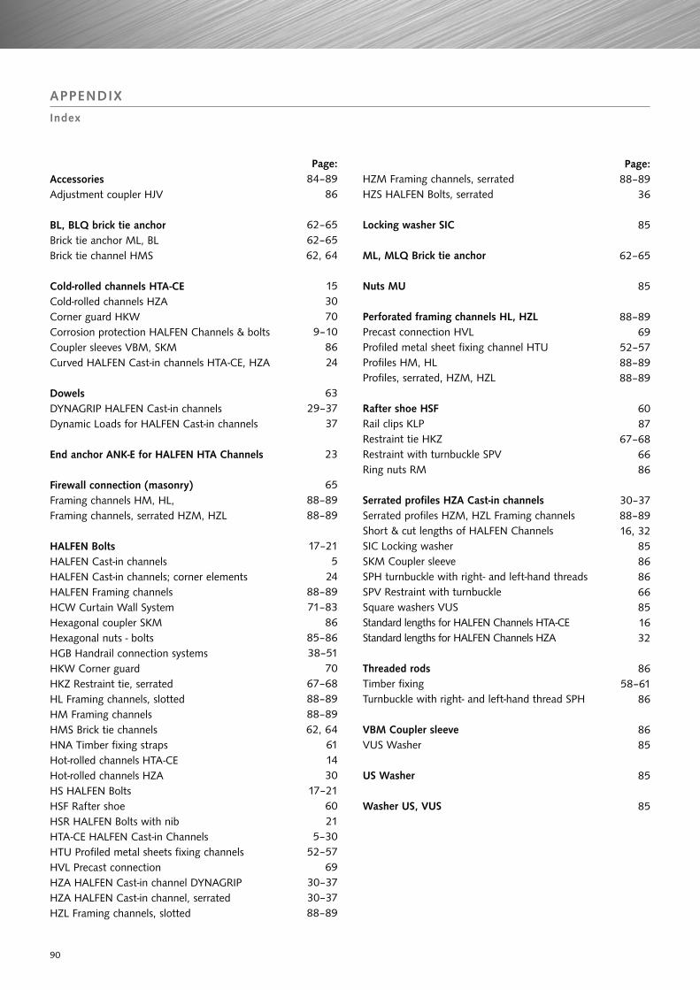
90
AccessoriesAdjustment coupler HJV
BL, BLQ brick tie anchorBrick tie anchor ML, BLBrick tie channel HMS
Cold-rolled channels HTA-CECold-rolled channels HZACorner guard HKWCorrosion protection HALFEN Channels & boltsCoupler sleeves VBM, SKMCurved HALFEN Cast-in channels HTA-CE, HZA
DowelsDYNAGRIP HALFEN Cast-in channelsDynamic Loads for HALFEN Cast-in channels
End anchor ANK-E for HALFEN HTA Channels
Firewall connection (masonry)Framing channels HM, HL,Framing channels, serrated HZM, HZL
HALFEN BoltsHALFEN Cast-in channelsHALFEN Cast-in channels; corner elementsHALFEN Framing channelsHCW Curtain Wall SystemHexagonal coupler SKMHexagonal nuts - boltsHGB Handrail connection systemsHKW Corner guardHKZ Restraint tie, serratedHL Framing channels, slottedHM Framing channelsHMS Brick tie channelsHNA Timber fixing strapsHot-rolled channels HTA-CEHot-rolled channels HZAHS HALFEN BoltsHSF Rafter shoeHSR HALFEN Bolts with nibHTA-CE HALFEN Cast-in ChannelsHTU Profiled metal sheets fixing channelsHVL Precast connectionHZA HALFEN Cast-in channel DYNAGRIPHZA HALFEN Cast-in channel, serrated HZL Framing channels, slotted
HZM Framing channels, serratedHZS HALFEN Bolts, serrated
Locking washer SIC
ML, MLQ Brick tie anchor
Nuts MU
Perforated framing channels HL, HZLPrecast connection HVLProfiled metal sheet fixing channel HTUProfiles HM, HLProfiles, serrated, HZM, HZL
Rafter shoe HSFRail clips KLPRestraint tie HKZRestraint with turnbuckle SPVRing nuts RM
Serrated profiles HZA Cast-in channelsSerrated profiles HZM, HZL Framing channelsShort & cut lengths of HALFEN ChannelsSIC Locking washerSKM Coupler sleeveSPH turnbuckle with right- and left-hand threadsSPV Restraint with turnbuckleSquare washers VUSStandard lengths for HALFEN Channels HTA-CEStandard lengths for HALFEN Channels HZA
Threaded rodsTimber fixingTurnbuckle with right- and left-hand thread SPH
VBM Coupler sleeveVUS Washer
US Washer Washer US, VUS
Page:84–89
86
62–6562–6562, 64
153070
9–108624
6329–37
37
23
6588–8988–89
17–215
2488–8971–83
8685–8638–51
7067–6888–8988–8962, 64
611430
17–216021
5–3052–57
6930–3730–3788–89
APPENDIX
Index
Page:88–89
36
85
62–65
85
88–8969
52–5788–8988–89
6087
67–686686
30–3788–8916, 32
85868666851632
8658–61
86
8685
85
85

www.dnvgl.com
NOTES REGARDING THIS CATALOGUETechnical and design changes reserved. The information in this publication is based on state-of-the-art technology at the time of publication. We reserve the right to make technical and design changes at any time. HALFEN GmbH shall not accept liability for the accuracy of the information in this publication or for any printing errors.
The HALFEN GmbH subsidiaries in Germany, France, the Netherlands, Austria, Poland, Switzerland and the Czech Republic are Quality Management certified according to ISO 9001:2015, Certificate no. 202384-2016-AQ-GER-DAkkS.
Austria HALFEN Gesellschaft m.b.H.Leonard-Bernstein-Str. 101220 Wien
Phone: +43 - 1 - 259 6770 E-Mail: [email protected]: www.halfen.at
Belgium / Luxembourg HALFEN N.V.Borkelstraat 1312900 Schoten
Phone: +32 - 3 - 658 07 20E-Mail: [email protected]: www.halfen.be
Fax: +32 - 3 - 658 15 33
China HALFEN Construction Accessories Distribution Co.Ltd.Room 601 Tower D, Vantone CentreNo. A6 Chao Yang Men Wai StreetChaoyang District Beijing · P.R. China 100020
Phone: +86 - 10 5907 3200E-Mail: [email protected]: www.halfen.cn
Fax: +86 - 10 5907 3218
Czech Republic HALFEN s.r.o.Business Center ŠafránkovaŠafránkova 1238/1155 00 Praha 5
Phone: +420 - 311 - 690 060E-Mail: [email protected]: www.halfen.cz
Fax: +420 - 235 - 314 308
France HALFEN S.A.S.18, rue Goubet75019 Paris
Phone: +33 - 1 - 445231 00E-Mail: [email protected]: www.halfen.fr
Fax: +33 - 1 - 445231 52
Germany HALFEN Vertriebsgesellschaft mbHLiebigstr. 14 40764 Langenfeld
Phone: +49 - 2173 - 970 - 0E-Mail: [email protected]: www.halfen.de
Fax: +49 - 2173 - 970 225
Italy HALFEN S.r.l. Soc. UnipersonaleVia F.lli Bronzetti N° 2824124 Bergamo
Phone: +39 - 035 - 0760711E-Mail: [email protected]: www.halfen.it
Fax: +39 - 035 - 0760799
Netherlands HALFEN b.v.Oostermaat 37623 CS Borne
Phone: +31 - 74-267 14 49E-Mail: [email protected]: www.halfen.nl
Fax: +31 - 74-267 26 59
Norway HALFEN ASPostboks 20804095 Stavanger
Phone: +47 - 51 82 34 00E-Mail: [email protected]: www.halfen.no
Poland HALFEN Sp. z o.o.Ul. Obornicka 28760-691 Poznan
Phone: +48 - 61 - 622 14 14E-Mail: [email protected]: www.halfen.pl
Fax: +48 - 61 - 622 14 15
Spain HALFEN IBERICA, S.L.Polígono Industrial Santa Ana c/ Ignacio Zuloaga 2028522 Rivas-Vaciamadrid
Phone: +34 - 91 632 18 40E-Mail: [email protected]: www.halfen.es
Fax: +34 - 91 633 42 57
Sweden Halfen ABVädursgatan 5412 50 Göteborg
Phone: +46 - 31 - 98 58 00E-Mail: [email protected]: www.halfen.se
Fax: +46 - 31 - 98 58 01
Switzerland HALFEN Swiss AGHertistrasse 25 8304 Wallisellen
Phone: +41 - 44 - 849 78 78E-Mail: [email protected]: www.halfen.ch
Fax: +41 - 44 - 849 78 79
United Kingdom /Ireland
HALFEN Ltd.A1/A2 Portland CloseHoughton Regis LU5 5AW
Phone: +44 - 1582 - 47 03 00E-Mail: [email protected]: www.halfen.co.uk
Fax: +44 - 1582 - 47 03 04
United States of America HALFEN USA Inc. PO Box 18687 San Antonio TX 78218
Phone: +1 800.423.91 40E-Mail: [email protected]: www.halfenusa.com
Fax: +1 877.683.4910
For countries not listed HALFEN International
HALFEN International GmbHLiebigstr. 14 40764 Langenfeld / Germany
Phone: +49 - 2173 - 970 - 0 E-Mail: [email protected]: www.halfen.com
Fax: +49 - 2173 - 970 - 849
CONTACT HALFEN WORLDWIDEHALFEN is represented by subsidiaries in the following countries, please contact us!

© 2
018
HA
LFEN
Gm
bH, G
erm
any
appl
ies
also
to
copy
ing
in e
xtra
cts.
B - 0
10 -
E - 1
1/18
PD
F 1
2/18
For further information please contact: www.halfen.com


