172
HAMILTON ARC System ARC View Handheld Operator's Guide Reference Version FW Version 024 PN 624298/01

HAMILTON ARC SystemARC View HandheldOperator's Guide Reference Version
FW Version 024
PN 624298/01
All rights reserved. No part of this document may be reproduced, stored in a retrieval system, or transmitted in any form without written permission from HAMILTON Bonaduz AG.
The contents of this manual are subject to change without notice. Technical changes reserved.
All efforts have been made to ensure the accuracy of the contents of this manual. However, should any errors be detected, HAMILTON Bonaduz AG would greatly appreciate being informed of them.
The above notwithstanding, HAMILTON Bonaduz AG can assume no responsibility for any errors in this manual or their consequences.
Copyright © 2010 HAMITLON Bonaduz AG, Switzerland.
Number Details
PN 624255/00 HAMILTON ARC System ARC View Handheld Operator’s GuideRevision 00. December 2009. FW Version 022.
PN 624255/01 HAMILTON ARC System ARC View Handheld Operator’s GuideRevision 01. April 2010. FW Version 023.
PN 624255/02 HAMILTON ARC System ARC View Handheld Operator’s GuideRevision 02. November 2010. FW Version 024.
PN 624298/00 HAMILTON ARC System ARC View Handheld Operator’s Guide Reference VersionRevision 00. April 2010. FW Version 023.
PN 624298/01 HAMILTON ARC System ARC View Handheld Operator’s Guide Reference VersionRevision 01. November 2010. FW Version 024.
List of Contents
List of Contents
List of Contents
ForewordAbout the ARC SystemAbout this manualHow to use this manual
Safety notices
Equipment warnings
Typographic standards in this manual
Section 1, Overview and theory
1.1 Getting started . . . . . . . . . . . . . . . . . . . . . . . . . . . . . . . . . . . . . . . . . . . . . . . . . . . . . . . 91.2 Setting up the ARC View Handheld . . . . . . . . . . . . . . . . . . . . . . . . . . . . . . . . . . . . . . . 101.3 ARC View Handheld keys and interface . . . . . . . . . . . . . . . . . . . . . . . . . . . . . . . . . . . 111.4 ARC View Handheld power management . . . . . . . . . . . . . . . . . . . . . . . . . . . . . . . . . . 161.5 ARC system components and principles . . . . . . . . . . . . . . . . . . . . . . . . . . . . . . . . . . . 17
1.5.1 ARC sensors: communications . . . . . . . . . . . . . . . . . . . . . . . . . . . . . . . . . . . . . . . 171.5.2 ARC sensors: operator levels . . . . . . . . . . . . . . . . . . . . . . . . . . . . . . . . . . . . . . . . 191.5.3 ARC sensors: operational status . . . . . . . . . . . . . . . . . . . . . . . . . . . . . . . . . . . . . . 201.5.4 ARC sensors: two kinds of calibration . . . . . . . . . . . . . . . . . . . . . . . . . . . . . . . . . . 231.5.5 ARC sensors: digital interface configuration . . . . . . . . . . . . . . . . . . . . . . . . . . . . . 251.5.6 ARC sensors: analog interface configuration . . . . . . . . . . . . . . . . . . . . . . . . . . . . 261.5.7 ARC sensors: Cleanings and Sterilizations In Place . . . . . . . . . . . . . . . . . . . . . . . 311.5.8 ARC sensor measurements: moving average . . . . . . . . . . . . . . . . . . . . . . . . . . . 321.5.9 ARC sensor measurements: resolution . . . . . . . . . . . . . . . . . . . . . . . . . . . . . . . . 32
1.5.10 ARC sensor measurements: temperature compensation factor . . . . . . . . . . . . . . 341.5.11 ARC sensor measurements: quality indicator . . . . . . . . . . . . . . . . . . . . . . . . . . . . 34
Section 2, Handheld tasks tutorial
2.1 Introduction . . . . . . . . . . . . . . . . . . . . . . . . . . . . . . . . . . . . . . . . . . . . . . . . . . . . . . . . . 372.2 User tasks . . . . . . . . . . . . . . . . . . . . . . . . . . . . . . . . . . . . . . . . . . . . . . . . . . . . . . . . . . 37
Task 1 Checking the status of all sensors in the ARC system . . . . . . . . . . . . . . . . . 37Task 2 Reading basic parameter values from a sensor . . . . . . . . . . . . . . . . . . . . . . 38
2.1 Reading basic parameter values in numeric form . . . . . . . . . . . . . . . . . . . . 382.2 Reading basic parameter values in graphic form . . . . . . . . . . . . . . . . . . . . . 38
Task 3 Reading detailed data from a sensor . . . . . . . . . . . . . . . . . . . . . . . . . . . . . . 393.1 Reading sensor status data . . . . . . . . . . . . . . . . . . . . . . . . . . . . . . . . . . . . . 393.2 Reading sensor information data . . . . . . . . . . . . . . . . . . . . . . . . . . . . . . . . . 403.3 Reading interface configuration data . . . . . . . . . . . . . . . . . . . . . . . . . . . . . . 40
ARC View Handheld Operator’s Guide 3
List of Contents
2.3 Administrator tasks . . . . . . . . . . . . . . . . . . . . . . . . . . . . . . . . . . . . . . . . . . . . . . . . . . . 40Task 1 Setting the Administrator operator level . . . . . . . . . . . . . . . . . . . . . . . . . . . . 41Task 2 Calibrating a sensor . . . . . . . . . . . . . . . . . . . . . . . . . . . . . . . . . . . . . . . . . . . 41
2.4 Specialist tasks . . . . . . . . . . . . . . . . . . . . . . . . . . . . . . . . . . . . . . . . . . . . . . . . . . . . . . 46Task 1 Setting the Specialist operator level . . . . . . . . . . . . . . . . . . . . . . . . . . . . . . . 46Task 2 Managing Handheld settings . . . . . . . . . . . . . . . . . . . . . . . . . . . . . . . . . . . . 47
2.1 Adjusting date and time settings . . . . . . . . . . . . . . . . . . . . . . . . . . . . . . . . . . 472.2 Configuring screen and Handheld power settings . . . . . . . . . . . . . . . . . . . . 472.3 Configuring ARC Handheld wireless settings . . . . . . . . . . . . . . . . . . . . . . . . 48
Task 3 Setting up a new sensor in an ARC system . . . . . . . . . . . . . . . . . . . . . . . . . 493.1 Entering the Sensor ID . . . . . . . . . . . . . . . . . . . . . . . . . . . . . . . . . . . . . . . . . 493.2 Configuring the Modbus device address . . . . . . . . . . . . . . . . . . . . . . . . . . . 503.3 Configuring the Baud rate . . . . . . . . . . . . . . . . . . . . . . . . . . . . . . . . . . . . . . . 503.4 Configuring the analog interface . . . . . . . . . . . . . . . . . . . . . . . . . . . . . . . . . . 503.5 Configuring a calibration . . . . . . . . . . . . . . . . . . . . . . . . . . . . . . . . . . . . . . . . 51
Task 4 Managing sensor STAtus profiles . . . . . . . . . . . . . . . . . . . . . . . . . . . . . . . . . 514.1 Creating a sensor STAtus profile file . . . . . . . . . . . . . . . . . . . . . . . . . . . . . . 524.2 Downloading a sensor STAtus profile . . . . . . . . . . . . . . . . . . . . . . . . . . . . . . 524.3 Reading a sensor STAtus profile file . . . . . . . . . . . . . . . . . . . . . . . . . . . . . . 53
Task 5 Managing trace files . . . . . . . . . . . . . . . . . . . . . . . . . . . . . . . . . . . . . . . . . . . 535.1 Creating a trace file . . . . . . . . . . . . . . . . . . . . . . . . . . . . . . . . . . . . . . . . . . . . 535.2 Downloading a trace file . . . . . . . . . . . . . . . . . . . . . . . . . . . . . . . . . . . . . . . . 535.3 Interpreting a trace file . . . . . . . . . . . . . . . . . . . . . . . . . . . . . . . . . . . . . . . . . 54
Task 6 Managing Sensor Configuration Files . . . . . . . . . . . . . . . . . . . . . . . . . . . . . . 556.1 Creating a Sensor Configuration File from a sensor . . . . . . . . . . . . . . . . . . . 566.2 Manually creating a Sensor Configuration File using a computer . . . . . . . . 566.3 Loading a Sensor Configuration File onto a sensor . . . . . . . . . . . . . . . . . . . 58
Section 3, Handheld screen reference
3.1 ARC View Handheld screens: full listing . . . . . . . . . . . . . . . . . . . . . . . . . . . . . . . . . . . 593.2 ARC View Handheld screens: full details . . . . . . . . . . . . . . . . . . . . . . . . . . . . . . . . . . 61
Section 4, Troubleshooting
4.1 Troubleshooting Wi wireless connections . . . . . . . . . . . . . . . . . . . . . . . . . . . . . . . . . . 1254.2 Troubleshooting Handheld sensor status colors . . . . . . . . . . . . . . . . . . . . . . . . . . . . . 1264.3 Troubleshooting ARC Wi Sensor Adapter status colors . . . . . . . . . . . . . . . . . . . . . . . 1274.4 Troubleshooting warning and status messages . . . . . . . . . . . . . . . . . . . . . . . . . . . . . 127
4.4.1 Measurement warnings . . . . . . . . . . . . . . . . . . . . . . . . . . . . . . . . . . . . . . . . . . . . . 1274.4.2 Calibration warnings . . . . . . . . . . . . . . . . . . . . . . . . . . . . . . . . . . . . . . . . . . . . . . . 1284.4.3 Calibration status messages . . . . . . . . . . . . . . . . . . . . . . . . . . . . . . . . . . . . . . . . . 1284.4.4 Interface warnings . . . . . . . . . . . . . . . . . . . . . . . . . . . . . . . . . . . . . . . . . . . . . . . . . 1294.4.5 Hardware warnings . . . . . . . . . . . . . . . . . . . . . . . . . . . . . . . . . . . . . . . . . . . . . . . . 130
4.5 Troubleshooting error messages . . . . . . . . . . . . . . . . . . . . . . . . . . . . . . . . . . . . . . . . . 1304.5.1 Measurement errors . . . . . . . . . . . . . . . . . . . . . . . . . . . . . . . . . . . . . . . . . . . . . . . 1304.5.2 Calibration errors . . . . . . . . . . . . . . . . . . . . . . . . . . . . . . . . . . . . . . . . . . . . . . . . . . 1314.5.3 Hardware errors . . . . . . . . . . . . . . . . . . . . . . . . . . . . . . . . . . . . . . . . . . . . . . . . . . 132
4

List of Contents
4.6 Restore Factory Settings . . . . . . . . . . . . . . . . . . . . . . . . . . . . . . . . . . . . . . . . . . . . . . . 132
Appendix A, ARC System components
A.1 HAMILTON ARC System core components . . . . . . . . . . . . . . . . . . . . . . . . . . . . . . . . 133A.5 HAMILTON ARC System documents . . . . . . . . . . . . . . . . . . . . . . . . . . . . . . . . . . . . . 137
Appendix B, ARC System firmware updates
B.1 Introduction . . . . . . . . . . . . . . . . . . . . . . . . . . . . . . . . . . . . . . . . . . . . . . . . . . . . . . . . . 139B.2 Handheld firmware update . . . . . . . . . . . . . . . . . . . . . . . . . . . . . . . . . . . . . . . . . . . . . . 140B.3 Handheld RF Module firmware update . . . . . . . . . . . . . . . . . . . . . . . . . . . . . . . . . . . . 141B.4 Dock firmware update . . . . . . . . . . . . . . . . . . . . . . . . . . . . . . . . . . . . . . . . . . . . . . . . . 142B.5 ARC sensor firmware update . . . . . . . . . . . . . . . . . . . . . . . . . . . . . . . . . . . . . . . . . . . . 143B.6 Wi Sensor Adapter firmware update . . . . . . . . . . . . . . . . . . . . . . . . . . . . . . . . . . . . . . 144
Appendix C, Sensor STAtus profile
C.1 Introduction . . . . . . . . . . . . . . . . . . . . . . . . . . . . . . . . . . . . . . . . . . . . . . . . . . . . . . . . . 145C.2 Sensor STAtus profile details . . . . . . . . . . . . . . . . . . . . . . . . . . . . . . . . . . . . . . . . . . . 145
Index
ARC View Handheld Operator’s Guide 5


Foreword
Foreword
About the ARC System
The HAMILTON ARC System is an advanced, integrated environment offering efficient and safe wireless and wired communication for the monitoring and management of sensors of many kinds.
Combining the cost savings and reliability of ARC sensors with the power, convenience, and portability of the ARC View Handheld management unit, users benefit from automated standard calibrations in the laboratory, product calibrations in the process environment, and instantaneous oversight of up to 30 sensors at all times.
About this manual
This manual is for all operators of the HAMILTON ARC process analytics system. The manual serves two functions:
• It gives an overview of the integration of the complete ARC system: sensors, cables, and ARC Wi Sensor Adapters.
• It explains in detail the use of the ARC View Handheld.
How to use this manual
First, make sure you are familiar with the Handheld’s basic functions, and that you understand what Users, Administrators and Specialists are. You can learn about these in Section 1, Overview and theory.
Then, try performing some of the tasks that your job requires of you. There is help about this in Section 2, Handheld tasks tutorial.
If you have difficulty understanding a screen or a field, use Section 3, Handheld screen reference. If you have difficulty finding the field you want, use the index in the back of the manual.
Safety notices
• The ARC View Handheld is environmentally protected to standard IP 67. The Dock, however, is not. For this reason, use the Dock only in dry locations.
• Do not open the power adapter.
• Do not use the ARC system or any ARC system component in an explosive environment (ATEX zones).
• Use only wired digital or analog connections for the process control. The ARC wireless interface is designed for sensor monitoring, maintenance, and service purposes.
ARC View Handheld Operator’s Guide 7

Equipment warnings
• Do not open the ARC View Handheld. Only trained service technicians are permitted to exchange the internal battery.
• Do not use the internal temperature sensor of any ARC sensor to control the temperature of a process.
Equipment warnings
• Do not use solvents, strong acids, bases, or ammonia (NH3) in gaseous or any other form to clean the ARC View Handheld or the Dock.
• Be sure not to damage the screen of the Handheld when cleaning. Small particles of dirt on a cloth can cause scratching. A new paper tissue is recommended.
Typographic standards in this manual
Example Explanation
Graph Courier font indicates text on the Handheld screen.
View Courier font, underlined, indicates a soft-key on the Handheld screen.
[Sensor] Courier font, italic with square brackets indicates a variable on the Handheld screen.[Sensor] indicates any ARC sensor shown on the Handheld screen.
8
Section 1 Overview and theory
Section 1 Overview and theory
This section gives a detailed description of the HAMILTON ARC View Handheld, and of the principles and theory that lie behind its use with other components in the ARC System.
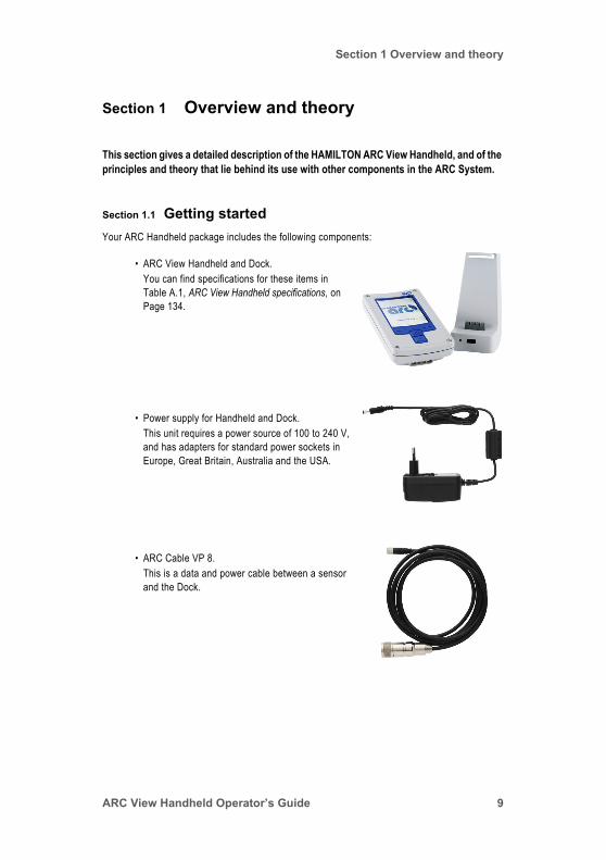
Section 1.1 Getting startedYour ARC Handheld package includes the following components:
• ARC View Handheld and Dock. You can find specifications for these items in Table A.1, ARC View Handheld specifications, on Page 134.
• Power supply for Handheld and Dock. This unit requires a power source of 100 to 240 V, and has adapters for standard power sockets in Europe, Great Britain, Australia and the USA.
• ARC Cable VP 8.This is a data and power cable between a sensor and the Dock.
ARC View Handheld Operator’s Guide 9

Section 1 Overview and theory
Section 1.2 Setting up the ARC View HandheldThe HAMILTON ARC Handheld is easy to set up and convenient to use as a configuration and calibration tool for HAMILTON ARC sensors.
The following steps describe the setup procedure for both wired and wireless connection options:
1. Connect the provided ARC Cable VP8 to the Dock.2. Connect one of the ARC sensors (not included in this package) to the VP8 plug of the
sensor cable.3. Place the ARC View Handheld in the Dock.4. Connect the Power Adapter Cable to the Dock, and plug the Power Adapter into an
suitable power outlet (100 to 240 V ac).5. Turn the Handheld on by pressing the Left and Right keys together for 3 seconds.
After startup, the Handheld recognizes and displays the connected sensor automatically.
NOTE: In this setup, the Handheld functions as a desktop system for a laboratory environment, not an industrial environment.
For wireless connection:
1. Plug the ARC Wi Sensor Adapter (not included in this package) between the ARC sensor and the sensor cable.
2. Take the Handheld out of the Dock. The wireless connection is established automatically.
NOTE: In this setup the Handheld can be used as a mobile tool for both laboratory and industrial applications.
Figure 1.1 Plugs on the ARC View Handheld Dock
ARC Cable VP8
Power Supply Cable
10
Section 1 Overview and theory
Section 1.3 ARC View Handheld keys and interfaceSwitching on and off
To switch on the Handheld, press the Left and Right Keys together for three seconds. To switch off the Handheld, press the Down Key for three seconds. For more information, see Section 1.4, ARC View Handheld power management, on Page 16.
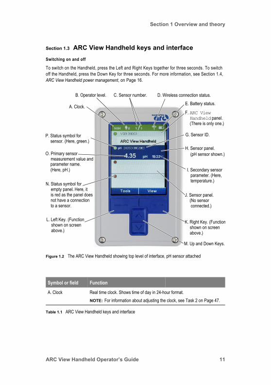
Figure 1.2 The ARC View Handheld showing top level of interface, pH sensor attached
Symbol or field Function
A. Clock Real time clock. Shows time of day in 24-hour format.NOTE: For information about adjusting the clock, see Task 2 on Page 47.
Table 1.1 ARC View Handheld keys and interface
C. Sensor number. D. Wireless connection status.E. Battery status.A. Clock.
B. Operator level.
F. ARC ViewHandheld panel. (There is only one.)
O. Primary sensormeasurement value andparameter name.
P. Status symbol for
N. Status symbol forempty panel. Here, itis red as the panel doesnot have a connection
L. Left Key. (Functionshown on screen
M. Up and Down Keys.
G. Sensor ID.
H. Sensor panel.(pH sensor shown.)
K. Right Key. (Functionshown on screen
I. Secondary sensorparameter. (Here,temperature.)
J. Sensor panel.(No sensor connected.)
(Here, pH.)
sensor. (Here, green.)
to a sensor.
above.) above.)
ARC View Handheld Operator’s Guide 11
Section 1 Overview and theory
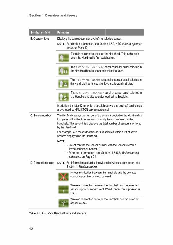
B. Operator level Displays the current operator level of the selected sensor.NOTE: For detailed information, see Section 1.5.2, ARC sensors: operator
levels, on Page 19.
There is no panel selected on the Handheld. This is the case when the Handheld is first switched on.
The ARC View Handheld panel or sensor panel selected in the Handheld has its operator level set to User.
The ARC View Handheld panel or sensor panel selected in the Handheld has its operator level set to Administrator.
The ARC View Handheld panel or sensor panel selected in the Handheld has its operator level set to Specialist.
In addition, the letter D (for which a special password is required) can indicate a level used by HAMILTON service personnel.
C. Sensor number The first field displays the number of the sensor selected on the Handheld as it appears within the list of sensors currently being monitored by the Handheld. The second field displays the total number of sensors monitored by the Handheld.For example, '4/7' means that Sensor 4 is selected within a list of seven sensors displayed on the Handheld.NOTE:
• Do not confuse the sensor number with the sensor's Modbus device address or Sensor ID.
• For more information, see Section 1.5.5.2, Modbus device addresses, on Page 25.
D. Connection status NOTE: For information about dealing with failed wireless connection, see Section 4, Troubleshooting.
No communication between the handheld and the selected sensor is possible, wireless or wired.
Wireless connection between the Handheld and the selected sensor is poor or non-existent. Wired connection, if present, is OK.
Wireless connection between the Handheld and the selected sensor is poor.
Symbol or field Function
Table 1.1 ARC View Handheld keys and interface
12
Section 1 Overview and theory
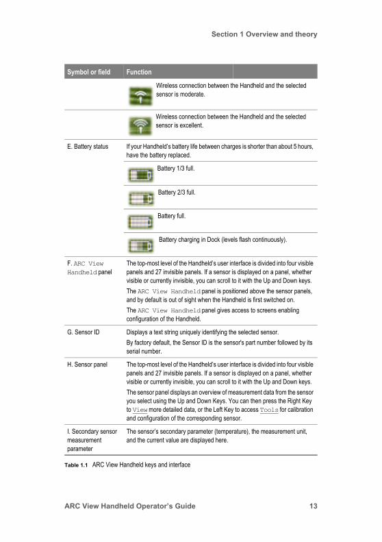
Wireless connection between the Handheld and the selected sensor is moderate.
Wireless connection between the Handheld and the selected sensor is excellent.
E. Battery status If your Handheld’s battery life between charges is shorter than about 5 hours, have the battery replaced.
Battery 1/3 full.
Battery 2/3 full.
Battery full.
Battery charging in Dock (levels flash continuously).
F. ARC View Handheld panel
The top-most level of the Handheld’s user interface is divided into four visible panels and 27 invisible panels. If a sensor is displayed on a panel, whether visible or currently invisible, you can scroll to it with the Up and Down keys.The ARC View Handheld panel is positioned above the sensor panels, and by default is out of sight when the Handheld is first switched on.The ARC View Handheld panel gives access to screens enabling configuration of the Handheld.
G. Sensor ID Displays a text string uniquely identifying the selected sensor.By factory default, the Sensor ID is the sensor's part number followed by its serial number.
H. Sensor panel The top-most level of the Handheld’s user interface is divided into four visible panels and 27 invisible panels. If a sensor is displayed on a panel, whether visible or currently invisible, you can scroll to it with the Up and Down keys.The sensor panel displays an overview of measurement data from the sensor you select using the Up and Down Keys. You can then press the Right Key to View more detailed data, or the Left Key to access Tools for calibration and configuration of the corresponding sensor.
I. Secondary sensor measurement parameter
The sensor’s secondary parameter (temperature), the measurement unit, and the current value are displayed here.
Symbol or field Function
Table 1.1 ARC View Handheld keys and interface
ARC View Handheld Operator’s Guide 13
Section 1 Overview and theory
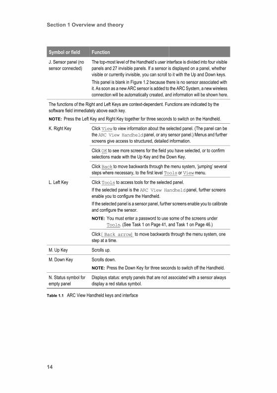
J. Sensor panel (no sensor connected)
The top-most level of the Handheld’s user interface is divided into four visible panels and 27 invisible panels. If a sensor is displayed on a panel, whether visible or currently invisible, you can scroll to it with the Up and Down keys.This panel is blank in Figure 1.2 because there is no sensor associated with it. As soon as a new ARC sensor is added to the ARC System, a new wireless connection will be automatically created, and information will be shown here.
The functions of the Right and Left Keys are context-dependent. Functions are indicated by the software field immediately above each key. NOTE: Press the Left Key and Right Key together for three seconds to switch on the Handheld.
K. Right Key Click View to view information about the selected panel. (The panel can be the ARC View Handheld panel, or any sensor panel.) Menus and further screens give access to structured, detailed information.
Click OK to see more screens for the field you have selected, or to confirm selections made with the Up Key and the Down Key.
Click Back to move backwards through the menu system, ‘jumping’ several steps where necessary, to the first level Tools or View menu.
L. Left Key Click Tools to access tools for the selected panel. If the selected panel is the ARC View Handheld panel, further screens enable you to configure the Handheld. If the selected panel is a sensor panel, further screens enable you to calibrate and configure the sensor. NOTE: You must enter a password to use some of the screens under
Tools. (See Task 1 on Page 41, and Task 1 on Page 46.)
Click [Back arrow] to move backwards through the menu system, one step at a time.
M. Up Key Scrolls up.
M. Down Key Scrolls down.NOTE: Press the Down Key for three seconds to switch off the Handheld.
N. Status symbol for empty panel
Displays status: empty panels that are not associated with a sensor always display a red status symbol.
Symbol or field Function
Table 1.1 ARC View Handheld keys and interface
14

Section 1 Overview and theory
O. Primary sensor measurement value and parameter name
The parameter shown in this field depends on the sensor displayed:• Cond = Conductivity• pH = pH• DO = Dissolved oxygenARC sensors measure a secondary parameter (always temperature) in addition to the primary one. The secondary parameter is shown to the right of the primary one.
P. Status symbol for sensor
Status colors for a sensor, shown on the Handheld (as here) and status colors on the ARC Wi Sensor Adapter do not have the same meaning.For more information, see:• Section 1.5.3, ARC sensors: operational status, on Page 20.• Section 4.2, Troubleshooting Handheld sensor status colors, on Page 126.
GREEN Continuous: Sensor and connection functioning correctly.Flashing: Updating data.
YELLOW Continuous: Sensor indicates error or warning message. Flashing: Updating data.
RED Continuous: Sensor or connection not functioning.
Symbol or field Function
Table 1.1 ARC View Handheld keys and interface
ARC View Handheld Operator’s Guide 15
Section 1 Overview and theory
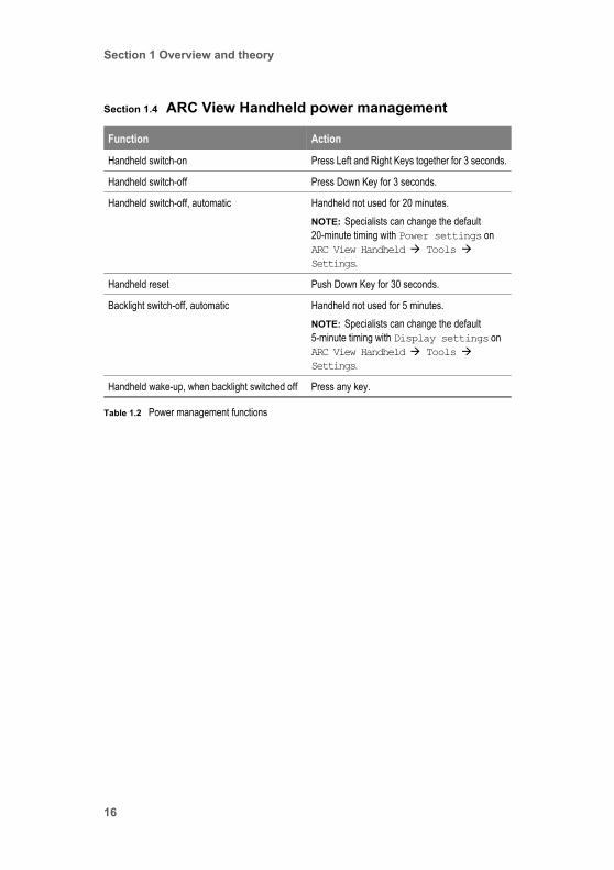
Section 1.4 ARC View Handheld power management
Function Action
Handheld switch-on Press Left and Right Keys together for 3 seconds.
Handheld switch-off Press Down Key for 3 seconds.
Handheld switch-off, automatic Handheld not used for 20 minutes.NOTE: Specialists can change the default 20-minute timing with Power settings on ARC View Handheld Tools Settings.
Handheld reset Push Down Key for 30 seconds.
Backlight switch-off, automatic Handheld not used for 5 minutes.NOTE: Specialists can change the default 5-minute timing with Display settings on ARC View Handheld Tools Settings.
Handheld wake-up, when backlight switched off Press any key.
Table 1.2 Power management functions
16
Section 1 Overview and theory
Section 1.5 ARC system components and principlesYou should be familiar with the following components and principles before operating the Handheld in a real working environment.
Section 1.5.1 ARC sensors: communications
Section 1.5.1.1 Overview
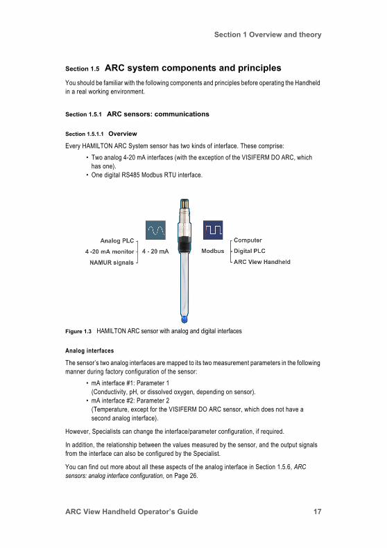
Every HAMILTON ARC System sensor has two kinds of interface. These comprise:• Two analog 4-20 mA interfaces (with the exception of the VISIFERM DO ARC, which
has one).• One digital RS485 Modbus RTU interface.
Analog interfaces
The sensor’s two analog interfaces are mapped to its two measurement parameters in the following manner during factory configuration of the sensor:
• mA interface #1: Parameter 1 (Conductivity, pH, or dissolved oxygen, depending on sensor).
• mA interface #2: Parameter 2 (Temperature, except for the VISIFERM DO ARC sensor, which does not have a second analog interface).
However, Specialists can change the interface/parameter configuration, if required.
In addition, the relationship between the values measured by the sensor, and the output signals from the interface can also be configured by the Specialist.
You can find out more about all these aspects of the analog interface in Section 1.5.6, ARC sensors: analog interface configuration, on Page 26.
Figure 1.3 HAMILTON ARC sensor with analog and digital interfaces
ARC View Handheld Operator’s Guide 17

Section 1 Overview and theory
Analog interface connections between a sensor and a control device such as a PLC are always wired.
Digital RS485 Modbus RTU interface
The sensor’s RS485 Modbus digital interface is used for wired connections to other hardware. An ARC Wi Sensor Adapter mounted on each ARC sensor is required for wireless connection, and provides the radio functionality. (However, the sensor also requires a separate, wired, power supply.)
Section 1.5.1.2 ARC sensor communication with a PLC system
Connection to a PLC system can be by means of the sensor’s analog or digital interfaces, depending on whether the process control system accepts analog or digital inputs. If necessary, both digital and analog interfaces can function at the same time.
For reasons of safety, connection to a process control system is always wired.
Section 1.5.1.3 ARC sensor communication with a Handheld
Sensor communication with a Handheld is always digital. It can be wired or wireless. Wired mode can be useful for testing, configuring, and calibrating sensors outside a process environment. Wireless mode (using an ARC Wi Sensor Adapter mounted on the sensor) is suitable for process environments.
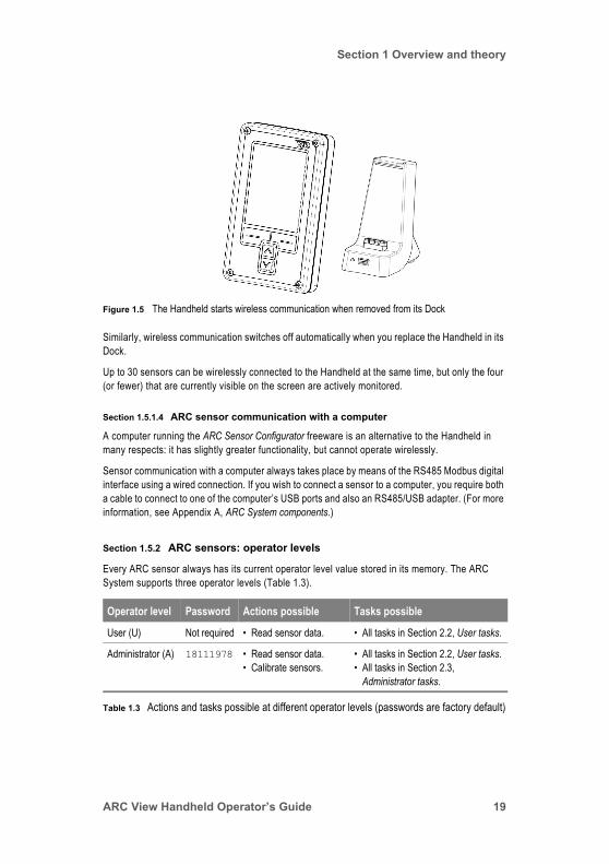
By default, wireless communication between the Handheld and the sensors starts automatically when you take the Handheld from its Dock (Figure 1.5).
Figure 1.4 HAMILTON pH ARC sensor, showing ARC Wi Sensor Adapter and cable
Cable for signal and power supply
ARC Wi Sensor Adapterfor wireless functionality
ARC sensor
VP8 Connector
18
Section 1 Overview and theory
Similarly, wireless communication switches off automatically when you replace the Handheld in its Dock.
Up to 30 sensors can be wirelessly connected to the Handheld at the same time, but only the four (or fewer) that are currently visible on the screen are actively monitored.
Section 1.5.1.4 ARC sensor communication with a computer
A computer running the ARC Sensor Configurator freeware is an alternative to the Handheld in many respects: it has slightly greater functionality, but cannot operate wirelessly.
Sensor communication with a computer always takes place by means of the RS485 Modbus digital interface using a wired connection. If you wish to connect a sensor to a computer, you require both a cable to connect to one of the computer’s USB ports and also an RS485/USB adapter. (For more information, see Appendix A, ARC System components.)
Section 1.5.2 ARC sensors: operator levels
Every ARC sensor always has its current operator level value stored in its memory. The ARC System supports three operator levels (Table 1.3).
Figure 1.5 The Handheld starts wireless communication when removed from its Dock
Operator level Password Actions possible Tasks possible
User (U) Not required • Read sensor data. • All tasks in Section 2.2, User tasks.
Administrator (A) 18111978 • Read sensor data.• Calibrate sensors.
• All tasks in Section 2.2, User tasks.• All tasks in Section 2.3,
Administrator tasks.
Table 1.3 Actions and tasks possible at different operator levels (passwords are factory default)
ARC View Handheld Operator’s Guide 19
Section 1 Overview and theory
On sensor power-up, a sensor falls back to the User operator level. This also happens when an operator working with the Handheld leaves the password-protected area of the Handheld.
When a sensor is set to the User operator level, it permits only User rights to any device accessing the data stored in its memory, and only User rights to perform some actions (Table 1.3).
However, by entering the Administrator or Specialist password in the Handheld, an operator can obtain Administrator or Specialist rights (Table 1.3).
Task 1, Setting the Administrator operator level, on Page 41 and Task 1, Setting the Specialist operator level, on Page 46 explain how you enter a password to obtain Administrator or Specialist rights.
Section 1.5.3 ARC sensors: operational status
Status colors on the Handheld and on the ARC Wi Sensor Adapter refer to the status of:• The sensor.• The sensor/Handheld connection.
NOTE: • The status colors do not refer to the status of the Handheld.• Status colors do not have the same meaning on the ARC Wi Sensor Adapter
that they do on the ARC View Handheld.
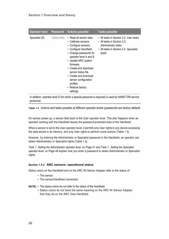
Specialist (S) 16021966 • Read all sensor data.• Calibrate sensors.• Configure sensors.• Configure Handheld.• Change passwords for
operator level A and S.• Update ARC system
firmware.• Create and download
sensor status file.• Create and download
sensor configuration profiles.
• Restore factory settings.
• All tasks in Section 2.2, User tasks.• All tasks in Section 2.3,
Administrator tasks.• All tasks in Section 2.4, Specialist
tasks.
In addition, operator level D (for which a special password is required) is used by HAMILTON service personnel.
Operator level Password Actions possible Tasks possible
Table 1.3 Actions and tasks possible at different operator levels (passwords are factory default)
20
Section 1 Overview and theory
Section 1.5.3.1 ARC View Handheld status colors
For help in correcting an unsatisfactory status, see Section 4.2, Troubleshooting Handheld sensor status colors, on Page 126.
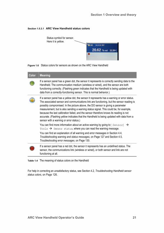
Figure 1.6 Status colors for sensors as shown on the ARC View Handheld
Color Meaning
If a sensor panel has a green dot, the sensor it represents is correctly sending data to the Handheld. The communication medium (wireless or wired), and the sensor are both functioning correctly. (Flashing green indicates that the Handheld is being updated with data from a correctly-functioning sensor. This is normal behavior.)
If a sensor panel has a yellow dot, the sensor it represents has a warning or error status. The associated sensor and communications link are functioning, but the sensor reading is possibly compromised. In the picture above, the DO sensor is giving a parameter measurement, but is also sending a warning status signal. This could be, for example, because the last calibration failed, and the sensor therefore knows its reading is not accurate. (Flashing yellow indicates that the Handheld is being updated with data from a sensor with a warning or error status.)You can find more information about an active warning by going to [Sensor] Tools Sensor status, where you can read the warning message.You can find an explanation of all warning and error messages in Section 4.4, Troubleshooting warning and status messages, on Page 127 and Section 4.5, Troubleshooting error messages, on Page 130.
If a sensor panel has a red dot, the sensor it represents has an undefined status. The sensor, the communications link (wireless or wired), or both sensor and link are not functioning at all.
Table 1.4 The meaning of status colors on the Handheld
Status symbol for sensor.Here it is yellow.
ARC View Handheld Operator’s Guide 21
Section 1 Overview and theory
Section 1.5.3.2 ARC Wi Sensor Adapter status colors
NOTE: Sensor Adapter status colors do not have the same meaning as Handheld status colors. For more information, see Section 1.5.3.1, ARC View Handheld status colors.
For help in correcting a red status, see Section 4.3, Troubleshooting ARC Wi Sensor Adapter status colors, on Page 127.
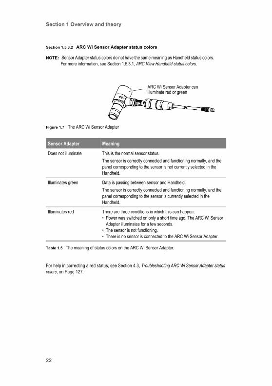
Figure 1.7 The ARC Wi Sensor Adapter
Sensor Adapter Meaning
Does not illuminate This is the normal sensor status. The sensor is correctly connected and functioning normally, and the panel corresponding to the sensor is not currently selected in the Handheld.
Illuminates green Data is passing between sensor and Handheld.The sensor is correctly connected and functioning normally, and the panel corresponding to the sensor is currently selected in the Handheld.
Illuminates red There are three conditions in which this can happen:• Power was switched on only a short time ago. The ARC Wi Sensor
Adapter illuminates for a few seconds.• The sensor is not functioning.• There is no sensor is connected to the ARC Wi Sensor Adapter.
Table 1.5 The meaning of status colors on the ARC Wi Sensor Adapter.
illuminate red or greenARC Wi Sensor Adapter can
22

Section 1 Overview and theory
Section 1.5.4 ARC sensors: two kinds of calibration
Section 1.5.4.1 Introduction
Calibration offsets the effects of time and wear on a sensor. Calibration of HAMILTON ARC Sensors can be carried out using:
• The ARC View Handheld• The ARC Sensor Configurator freeware on a PC.• The HAMILTON VisiCal device.• A digital control unit (PLC, or PC Software) using the corresponding Modbus
commands.
NOTE: In this manual, we will confine ourselves to calibration with the ARC View Handheld.
The ARC View Handheld offers two kinds of sensor calibration: automatic standard calibration, and product calibration.
With automatic standard calibration, a sensor is calibrated outside of its process environment, using a standard medium of known value against which the sensor reading is compared. For instance, a pH sensor can be calibrated against a standard solution of known pH, or a dissolved oxygen sensor can be calibrated against the oxygen in air. The expression ‘automatic’ signifies that ARC sensors have the ability (within certain limits) to recognize the standard into which they are placed, and to configure themselves appropriately for calibration against that standard. You can see a list of standards appropriate for use with ARC sensors on Table 2.2, Sensor calibration standards, on Page 42.
With product calibration, a sensor is calibrated within its process environment. In this case, a sensor reading is taken at the same time a sample is taken from the process. The sample is analyzed offline in the laboratory, and the offline result used to correct the sensor reading.
NOTE: With the HAMILTON ARC system, only the primary parameter of a sensor can be calibrated (dissolved oxygen for a DO sensor, conductivity for a Cond sensor, pH for a pH sensor). Temperature is the secondary parameter in every ARC sensor, and cannot be calibrated.
Section 1.5.4.2 Calibration theory
Calibration of dissolved oxygen and pH ARC sensors takes place at two calibration points. Calibration of conductivity ARC sensors takes place at just one point. During calibration at each point, sensors are exposed to a defined and strictly-controlled environment, and their readings compensated against the known conditions of that environment. For example, the VISIFERM DO ARC sensor is calibrated:
• In an environment of 0% oxygen at its first calibration point.• In an environment of atmospheric oxygen at its second calibration point.
This is shown in Figure 1.8. Here, the two calibration points are used to define a calibration curve to map the luminescence phase shift (the raw measurement underlying the sensor's primary parameter) against the stated primary parameter, namely, dissolved oxygen.
ARC View Handheld Operator’s Guide 23

Section 1 Overview and theory
This curve is then used to interpret luminescence phase shift values during sensor operation, to give accurate dissolved oxygen measurements.
At each calibration point, the calibration process is as follows:
1. The Handheld sends the calibration command to the ARC Sensor.2. The sensor software analyzes the measurement data stored in its internal memory
over the past three minutes, and if the criteria for signal stability, calibration range and temperature are met, the calibration values for this calibration point are calculated and immediately made active.
3. If the measurement values are drifting or the standard is not recognized, several attempts for calibration will be made automatically for at most 180 seconds.
4. As soon as the measurement values are stable, the sensor will proceed as described in point 2.
5. If the calibration is not successful during the 180 seconds, the calibration procedure will be cancelled.
NOTE: • If calibration fails at one of the calibration points, the sensor can still be used. However, the measured value can be compromised. Measurement reliability is expressed as the Quality indicator field in [Sensor] View Sensor status.
• If the sensor does not recognize the standard for at most 180 seconds after initiating the calibration, calibration will be cancelled automatically with a corresponding warning message.
• If the measurement values are not stable for at most 180 seconds after initiating the calibration, calibration will be cancelled automatically with a corresponding warning message.
• If calibration fails, a warning message is displayed. For more information, see Section 4.4.3, Calibration status messages, on Page 128.
Figure 1.8 Calibration of the primary parameter at two points using a VISIFERM DO ARC sensor
Oxygen (%-vol)
Lumi
nesc
ence
phas
e shif
t (°)
24
Section 1 Overview and theory
Section 1.5.5 ARC sensors: digital interface configuration
Section 1.5.5.1 Introduction
Configuration of an ARC sensor digital interface is quite simple. There are only two parameters:• Modbus device address• Baud rate
NOTE: Specialists configure the digital interface on screens accessed from [Sensor] Tools Interface configuration Digital RS485.
Section 1.5.5.2 Modbus device addresses
Background
Modbus is a digital serial communications protocol published by Modicon for use with its programmable logic controllers (PLCs). It has become a standard communications protocol, and is now a commonly available means of connecting industrial electronic devices.
Modbus allows for communication between many devices connected to the same network, for example, a system that measures temperature and humidity and communicates the results to a computer.
HAMILTON uses a Modbus protocol in which there is one master device (the PLC or ARC View Handheld) and numerous passive slave devices (the sensors). The master device transmits a Modbus device address to establish a communications link with a sensor. All sensors that do not have this address ignore the transmission.
The HAMILTON Modbus protocol is described in detail in the VISIFERMTM DO Modbus RTU Programmer’s Manual, PN 624179. See also Appendix A.5, HAMILTON ARC System documents, on Page 137.
Modbus device addresses and sensors
An ARC sensor’s Modbus device address uniquely identifies an ARC sensor with respect to its digital communications with the PLC. The address is represented by a number in the range 1 to 30.
NOTE: Do not confuse the Modbus device address of a sensor with its Sensor ID or Sensor Number. For more information about Sensor IDs or Sensor Numbers, see:• Figure 1.2, The ARC View Handheld showing top level of interface, pH sensor
attached.• Table 1.1, ARC View Handheld keys and interface.
By default, every ARC sensor has a Modbus device address of 1. This is set at the factory during the sensor’s production. Because of this, a new Modbus device address (in other words, not 1) must be configured for every ARC sensor that is added to an ARC System with a digital PLC, thereby making sure that every sensor in the System has a unique address. (If two sensors have the same address, then when the PLC transmits an address, only the quicker of the two sensors responds).
ARC View Handheld Operator’s Guide 25

Section 1 Overview and theory
Section 1.5.5.3 Baud rates
The Baud rate affects the wired connection made by an ARC sensor’s RS485 Modbus digital interface. It has no influence on the analog connection between a sensor and an analog PLC system. It is therefore only critical for wired connections between ARC sensors and digital PLC systems.
Naturally, higher Baud rates equate to quicker communications between sensors and other hardware. However, higher Baud rates can lead to unreliable connections in some instances. A typical example of this is a long cable connection between a sensor and a digital PLC system. It is not possible to be specific about cable lengths or to offer recommendations, because variables such as cable quality and local interference are as important as cable length.
If you have a digital PLC system, you must experiment to find the best combination of speed and reliability.
Section 1.5.6 ARC sensors: analog interface configuration
NOTE: Specialists configure the analog interface using screens accessed from [Sensor] Tools Interface configuration.
Section 1.5.6.1 Introduction
All ARC sensors have two analog interfaces (with the exception of the VISIFERM DO ARC, which has one). Normally, you use one analog interface for one measurement parameter. For example, by default, the Easyferm Plus sensor uses mA interface #1 for its primary parameter (pH) and mA interface #2 for its secondary parameter (temperature).
However, you do not have to keep the default settings. You might even want to configure the sensor’s primary parameter so that it is output on both analog interfaces. You could then further configure each interface, for example, optimizing mA interface #1 for pH readings between pH 3 and pH 4, and optimizing mA interface #2 for readings between pH 6 and pH 7.
You can configure each of a sensor’s analog interfaces independently.
NOTE: Analog interface configuration is for both of a sensor’s parameters. Sensor calibration (for measurement accuracy) is for only a sensor’s primary parameter. (See Section 1.5.4, ARC sensors: two kinds of calibration, on Page 23).
There are four aspects to configuring an analog interface:• Selecting the interface/parameter combination. (Section 1.5.6.2, Mapping sensor
measurement parameters to analog interfaces).• Selecting the interface mode for the interface and parameter selected. (Section
1.5.6.3, Configuring the mode of the analog interfaces).• Configuring the output current for the interface mode. (Section 1.5.6.4, Configuring the
output current of the analog interfaces).• Configuring errors and warnings for the interface mode. (Section 1.5.6.5, Configuring
errors and warnings).
26
Section 1 Overview and theory
Section 1.5.6.2 Mapping sensor measurement parameters to analog interfaces
Introduction
Specialists must first define the interface/parameter combination to they will later configure. Remember that pH and conductivity sensors have two analog interfaces, but dissolved oxygen sensors, only one. This means that for pH and conductivity sensors, there are two interface/parameter relationships to map.
Configuration
Specialists map parameters to interfaces by:
1. Selecting an analog interface.They do this on [Sensor] Tools Interface configuration.
2. Selecting the parameter they wish to map to the analog interface already selected.They do this with the Measurement variable field on [Sensor] Tools Interface configuration mA interface #1 [or #2, or mA/ECS-
Interface] Output current configuration.
Section 1.5.6.3 Configuring the mode of the analog interfaces
Introduction
An analog interface can operate in one of three ways:
• Measurement:The output of the 4-20 mA interface is a function of the value of the measurement parameter mapped onto it.
• Test:The output of the 4-20 mA interface is a constant signal. This could be used, for example, for testing the 4-20 mA current loop.
• Switched off:The 4-20 mA interface gives no signal.
Configuration
In reality, choice of sensor analog interface mode requires that a number of further choices are made by the Specialist. These are discussed in Section 1.5.6.4.
Section 1.5.6.4 Configuring the output current of the analog interfaces
Introduction
Specialists can configure the way in which each analog interface of the sensor sends information to the PLC system. Specialists do this by defining the relationship between the value measured by the sensor (for instance, the pH 7), and the electric current transmitted to the PLC system (for instance, 10 mA).
ARC View Handheld Operator’s Guide 27

Section 1 Overview and theory
NOTE: Specialists configure the analog interface output current starting on [Sensor] Tools Interface configuration mA interface #1 [or #2, or mA/ECS-Interface] Interface mode.
Configuration
In Section 1.5.6.3, the Specialist decided on the operation mode of the interface:• Measurement.• Test.• Switched off.
If the Specialist is using the interface for measurements, he must now decide whether the relationship between the measured value and the output current is to be determined by two points as a straight-line graph, or by three points as a two-straight-line graph. These options are called 4–20 mA linear, and 4–20 mA interface bilinear, and are explained in Table 1.6, on Page 28.
If the Specialist wants to use the interface for test purposes, he requires 4–20 mA fixed. This is also shown in Table 1.6, on Page 28.
If the Specialists does not require the interface, he sets OFF.
If the Specialist wants to use the interface for measurement, he now configures values for the relationship (linear or bilinear) he has selected. If he is using a test mode, he defines a fixed value for the test mode.
NOTE: The Specialist configures values on [Sensor] Tools Interface configuration mA interface #1 [or #2, or mA/ECS-Interface] Output current configuration.
The task of the Specialist is to configure the sensor signal sent to the analog PLC in a way that emphasizes the measurement range that is of most interest. For instance, if the pH in the process is always in the range pH 4 to pH 6, then the Specialist configures the signal for this range, and allows measurement values outside pH 4 to pH 6 to fall out of 4-20 mA range of the analog interface.
Mode Explanation
OFF The analog interface is switched off. No signals are sent.
4–20 mA fixed The interface sends a continuous fixed signal for test purposes.NOTE: Specialists can configure this fixed test signal on [Sensor] Tools Interface configuration mA interface #1 [or #2, or mA/ECS-Interface] Output current configuration.
Table 1.6 Explanation of interface modes configured on [Sensor] Tools Interfaceconfiguration mA interface #1 [or #2, or mA/ECS-Interface] Interface mode
28

Section 1 Overview and theory
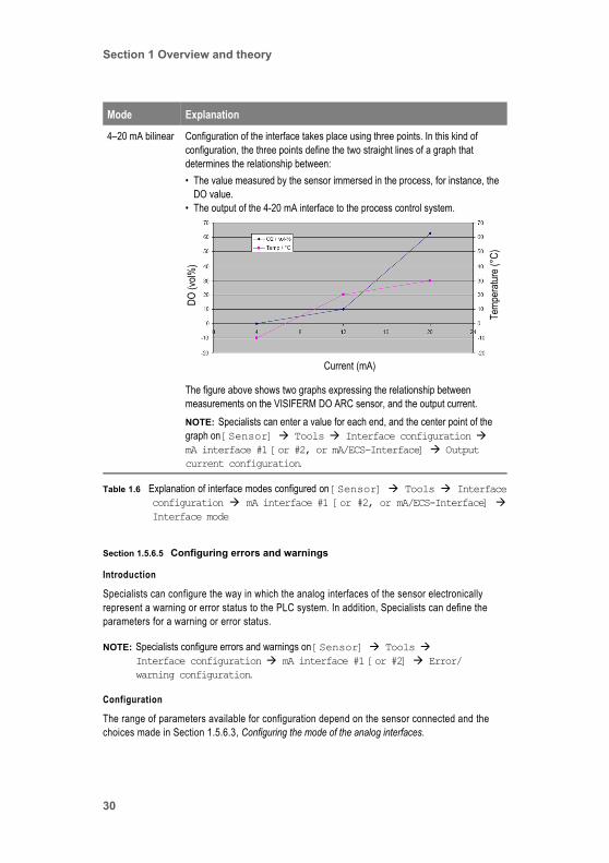
4–20 mA linear Configuration of the interface takes place using two points. In this kind of configuration, the two points become the ends of a straight-line graph that determines the relationship between:• The value measured by the sensor immersed in the process, for instance, the
DO value.• The output of the 4-20 mA interface to the process control system.
The figure above shows two virtual straight-line graphs expressing the relationship between measurements on the VISIFERM DO ARC sensor, and interface’s output current. The graphs are for dissolved oxygen and for temperature. (Both parameters cannot be mapped to the single analog interface at the same time.)NOTE: Specialists can enter a value for each end of the graph on [Sensor] Tools Interface configuration mA interface #1 [or
#2, or mA/ECS-Interface] Output current configuration.
Mode Explanation
Table 1.6 Explanation of interface modes configured on [Sensor] Tools Interfaceconfiguration mA interface #1 [or #2, or mA/ECS-Interface] Interface mode
Current (mA)
DO (v
ol%)
Temp
eratu
re (°
C)
ARC View Handheld Operator’s Guide 29
Section 1 Overview and theory
Section 1.5.6.5 Configuring errors and warnings
Introduction
Specialists can configure the way in which the analog interfaces of the sensor electronically represent a warning or error status to the PLC system. In addition, Specialists can define the parameters for a warning or error status.
NOTE: Specialists configure errors and warnings on [Sensor] Tools Interface configuration mA interface #1 [or #2] Error/warning configuration.
Configuration
The range of parameters available for configuration depend on the sensor connected and the choices made in Section 1.5.6.3, Configuring the mode of the analog interfaces.
4–20 mA bilinear Configuration of the interface takes place using three points. In this kind of configuration, the three points define the two straight lines of a graph that determines the relationship between:• The value measured by the sensor immersed in the process, for instance, the
DO value.• The output of the 4-20 mA interface to the process control system.
The figure above shows two graphs expressing the relationship between measurements on the VISIFERM DO ARC sensor, and the output current.NOTE: Specialists can enter a value for each end, and the center point of the graph on [Sensor] Tools Interface configuration mA interface #1 [or #2, or mA/ECS-Interface] Output current configuration.
Mode Explanation
Table 1.6 Explanation of interface modes configured on [Sensor] Tools Interfaceconfiguration mA interface #1 [or #2, or mA/ECS-Interface] Interface mode
Current (mA)
DO (v
ol%)
Temp
eratu
re (°
C)
30
Section 1 Overview and theory
The complete list of fields is shown on [Sensor] Tools Interface configuration mA interface #1 [or #2] Error/warning configuration.
Section 1.5.7 ARC sensors: Cleanings and Sterilizations In Place
Cleanings In Place (CIPs) and Sterilizations In Place (SIPs) are both supported by the ARC System.
NOTE: All operators can see, and Specialists can configure, the definitions and total number of CIPs and SIPs for a sensor. They do this [Sensor] Tools Calibration Calibration data.
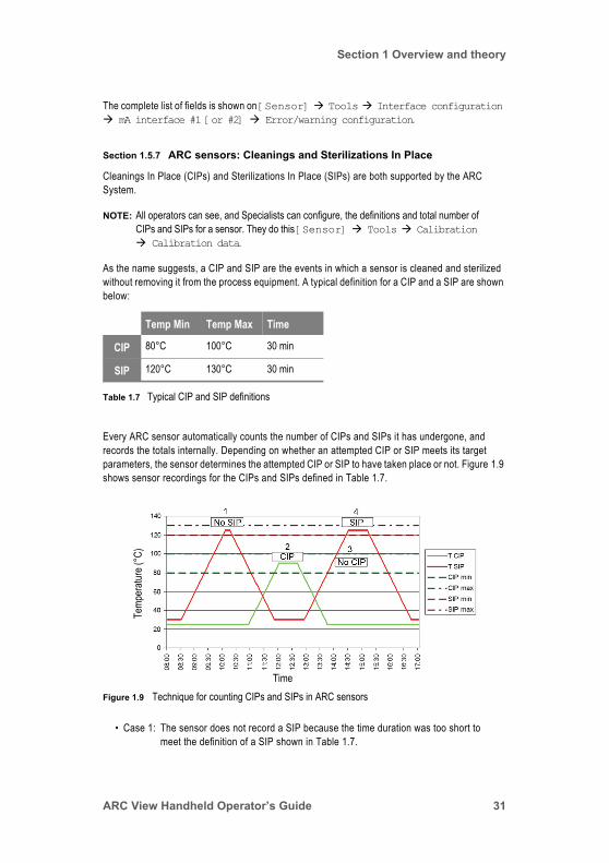
As the name suggests, a CIP and SIP are the events in which a sensor is cleaned and sterilized without removing it from the process equipment. A typical definition for a CIP and a SIP are shown below:
Every ARC sensor automatically counts the number of CIPs and SIPs it has undergone, and records the totals internally. Depending on whether an attempted CIP or SIP meets its target parameters, the sensor determines the attempted CIP or SIP to have taken place or not. Figure 1.9 shows sensor recordings for the CIPs and SIPs defined in Table 1.7.
• Case 1: The sensor does not record a SIP because the time duration was too short to meet the definition of a SIP shown in Table 1.7.
Temp Min Temp Max Time
CIP 80°C 100°C 30 min
SIP 120°C 130°C 30 min
Table 1.7 Typical CIP and SIP definitions
Figure 1.9 Technique for counting CIPs and SIPs in ARC sensorsTime
Temp
eratu
re (°
C)
ARC View Handheld Operator’s Guide 31

Section 1 Overview and theory
• Case 2: The sensor records a CIP because the time and temperature were in range.• Case 3: The sensor does not record a CIP because the temperature continues to rise
above the upper maximum for a CIP. Instead, the SIP at Point 4 is recorded.• Case 4: The sensor records a SIP because the time and temperature were in range.
Both CIPs and SIPs are wearing the sensors, and are the main cause for the limited sensor life of sensors from all manufacturers. Typically, sensors can withstand 50 to 100 CIPs and SIPs, depending on the temperature and time duration of the events, and also depending on whether cleaning and sterilization agents are used.
With experience, operators can combine the information found on [Sensor] Tools Measurement CIP/SIP definition about the number of CIPs and SIPs that a sensor has undergone, together with their knowledge of the kind of CIPs and SIPs used, to estimate the remaining life-span of their sensors.
Section 1.5.8 ARC sensor measurements: moving average
A moving average is a window during which a sensor looks backwards in time, averaging its latest reading within the window. The use of averaged readings can be preferable when real readings fluctuate greatly. This is because an averaged reading is a better indication of an underlying trend than are many, variable readings.
NOTE: • A Specialist sets the moving average for a sensor on [Sensor] Tools Measurement.
• Do not confuse a reading (of which there can be many in a moving average) with the resolution value (VISIFERM DO ARC only). Resolution is explained in Section 1.5.9, ARC sensor measurements: resolution.
• Moving averages are explained in the VISIFERMTM DO Modbus RTU Programmer’s Manual, PN 624179 and other documents in Appendix A.5, HAMILTON ARC System documents, on Page 137.
A moving average improves signal stability over the short term. However, the response time of the sensor increases (degrades) with the increased moving average. For example, VISIFERM DO ARC calculates a new oxygen reading every three seconds. You can smooth this reading by means of a moving average (Figure 1.10, on Page 33). However, a moving average applied to 20 three-second readings results in a response time of at least 60 seconds. The Specialist can set the number of readings in the moving average array between 1 and 16 (pH and conductivity sensors), or 1 and 30 (DO sensor), or can enter a value of zero (0) to activate the automatic mode, in which the sensor varies this setting depending on the measuring signal trend.
Section 1.5.9 ARC sensor measurements: resolution
With respect to ARC sensor measurements, the expression resolution refers to the number of sub-measurements underlying a recorded measurement made by the VISIFERM DO ARC sensor. The expression is not used with any other kind of sensor, and the Resolution field is only available on the Handheld for dissolved oxygen sensors.
32

Section 1 Overview and theory
NOTE: The Specialist sets the resolution for a VISIFERM DO ARC sensor on [Sensor] Tools Measurement.
The measurement made by VISIFERM DO ARC in each 3-second interval is, in reality, the average of up to 16 sub-measurements (Figure 1.11, on Page 33). The Specialists can set the number of
sub-measurements between 1 and 16, or can enter a value of zero (0) to activate the automatic mode, in which the sensor varies this setting depending on the measuring signal trend.
The advantage of using a lower resolution is the shorter period of exposure of the luminophore to the excitation light. This reduces the photo bleaching of the luminophore and enhances its lifetime, and therefore the lifetime of the sensor. The advantage of using a higher resolution is enhanced signal quality.
Figure 1.10 Comparison of the response of VISIFERM DO ARC to a change from air to nitrogen, using n=1 (no moving average) or a moving average of n=20
Figure 1.11 Comparison of signal stability of VISIFERM DO ARC when using a resolution of 1 and 16
Effects of Moving Average (n=1 and n=20)Ox
ygen
%-vo
l
Time
Effects of Resolution (1 and 16) on Stability
Oxyg
en%
-vol
Time
(Moving Average = 1 in both cases)
Resolution = 1 Resolution = 16
ARC View Handheld Operator’s Guide 33
Section 1 Overview and theory
Section 1.5.10 ARC sensor measurements: temperature compensation factor
With respect to ARC sensor measurements, the expression temperature compensation factor refers to an adjustment that an Specialist can make to compare the conductivity measurements at different temperatures. It provides an estimate of the sample‘s conductivity at a common reference temperature (25°C). The Temp. comp. factor field is available on the Handheld for conductivity sensors only.
NOTE: The Specialist sets the temperature compensation factor for a Conducell 4USF sensor on [Sensor] Tools Measurement.
The temperature compensation factor is the rate at which a solution’s conductivity increases with an increase of temperature and is expressed as the percentage increase of conductivity for a temperature rise of 1 °C. The compensation factor chosen by the Specialist must be dependent on the liquid being monitored by the sensor.
Section 1.5.11 ARC sensor measurements: quality indicator
With respect to ARC sensor measurements, the expression quality indicator refers to an estimate made by the sensor of the reliability of its primary reading: conductivity, pH, or dissolved oxygen (not temperature, which is the secondary reading). The Quality indicator field is available for all ARC sensors and represents the sensor condition in six gradations: Excellent, High, Acceptable, Poor, Very Poor, Defective.
NOTE: All operators can see the Quality indicator for a measurement on [Sensor] View Sensor status.
The calculation of the quality indicator for a sensor takes into consideration a number of factors, some sensor-specific, and some general. Sensor-specific considerations include:
• Dissolved oxygen sensors: luminophore status is continuously monitored.• pH sensors: 0 (zero) point position and slope of the pH calibration curve is checked
following calibration.• Conductivity sensors: Cell constant of the sensor is checked following calibration.
General considerations for the calculation of the quality indicator include:
• The quality of the most recent calibration. If a calibration fails at one of the calibration points and a calibration warning message is generated, this does not necessarily mean that the sensor cannot be used. In event of failure at a calibration point, the sensor uses its most recent successful calibration data, but the quality indicator can degrade.
• Because the accuracy and reliability of all sensors can decline with use:• The number of Cleanings In Place (CIPs) the sensor has undergone.• The number of Sterilizations In Place (SIPs) the sensor has undergone.
(For more information about CIPs and SIPs, see Section 1.5.7, ARC sensors: Cleanings and Sterilizations In Place, on Page 31.)
34

Section 1 Overview and theory
• The number of operating hours at different temperatures. (You can see these statistics on [Sensor] View Sensor status Total operating hours).
ARC View Handheld Operator’s Guide 35

Section 1 Overview and theory
36
Section 2 Handheld tasks tutorial
Section 2 Handheld tasks tutorial
This section offers an introduction to the main tasks that operators—Users, Administrators, and Specialists—perform on a regular basis for a HAMILTON ARC System, using the HAMILTON ARC View Handheld.
Section 2.1 IntroductionThis section guides you through some of the tasks that operators perform with the ARC System on a daily basis. Before starting this section, you must understand the different levels of access that Users, Administrators, and Specialists have to the ARC System. For more information, see Section 1.5.2, ARC sensors: operator levels, on Page 19.
Administrators and Specialists must enter a password to perform Administrator-level and Specialist-level tasks.
Section 2.2 User tasksThe User has the lowest level of access to the ARC System of all operator types: he or she can only check the status of the System, and read measurements made by sensors in the System.
Task 1 Checking the status of all sensors in the ARC system
Introduction
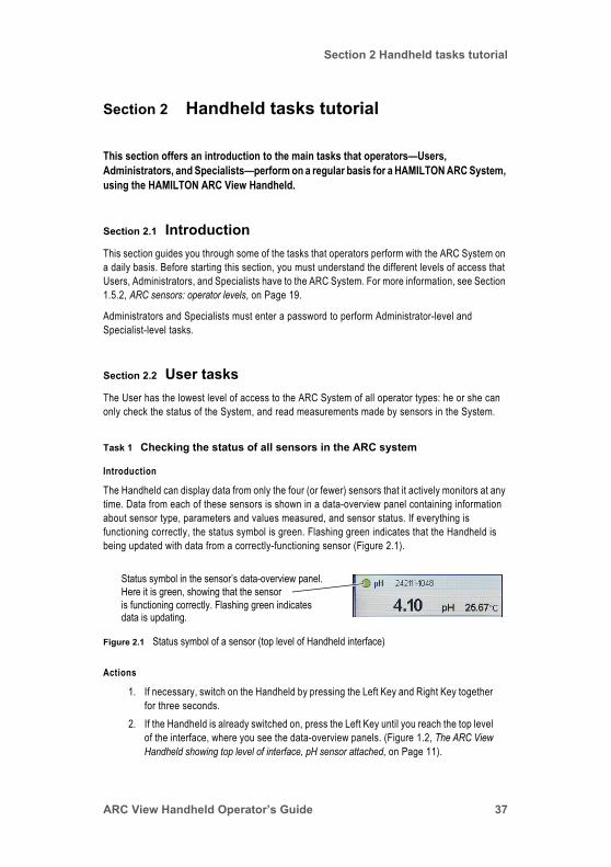
The Handheld can display data from only the four (or fewer) sensors that it actively monitors at any time. Data from each of these sensors is shown in a data-overview panel containing information about sensor type, parameters and values measured, and sensor status. If everything is functioning correctly, the status symbol is green. Flashing green indicates that the Handheld is being updated with data from a correctly-functioning sensor (Figure 2.1).
Actions
1. If necessary, switch on the Handheld by pressing the Left Key and Right Key together for three seconds.
2. If the Handheld is already switched on, press the Left Key until you reach the top level of the interface, where you see the data-overview panels. (Figure 1.2, The ARC View Handheld showing top level of interface, pH sensor attached, on Page 11).
Figure 2.1 Status symbol of a sensor (top level of Handheld interface)
Status symbol in the sensor’s data-overview panel.Here it is green, showing that the sensoris functioning correctly. Flashing green indicatesdata is updating.
ARC View Handheld Operator’s Guide 37
Section 2 Handheld tasks tutorial
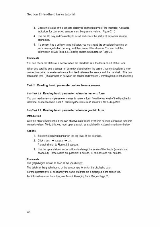
3. Check the status of the sensors displayed on the top level of the interface. All status indicators for connected sensors must be green or yellow. (Figure 2.1.)
4. Use the Up Key and Down Key to scroll and check the status of any other sensors connected.
5. If a sensor has a yellow status indicator, you must read the associated warning or error message to find out why, and then correct the situation. You can find this information in Sub-Task 3.1, Reading sensor status data, on Page 39.
Comments
You can check the status of a sensor when the Handheld is in the Dock or out of the Dock.
When you scroll to see a sensor not currently displayed on the screen, you must wait for a new connection (wired or wireless) to establish itself between the sensor and the Handheld. This can take some time. (The connection between the sensor and Process Control System is not affected.)
Task 2 Reading basic parameter values from a sensor
Sub-Task 2.1 Reading basic parameter values in numeric form
You can read a sensor’s parameter values in numeric form from the top level of the Handheld’s interface, as mentioned in Task 1, Checking the status of all sensors in the ARC system.
Sub-Task 2.2 Reading basic parameter values in graphic form
Introduction
With the ARC View Handheld you can observe data trends over time periods, as well as real-time numeric values. To do this, you must open a graph, as explained in Actions immediately below.
Actions
1. Select the required sensor on the top level of the interface.2. Click View Graph OK.
A graph similar to Figure 2.2 appears.3. Use the up and down arrow buttons to change the scale of the X-axis (zoom in and
zoom out). Three scales are possible: 1 minute, 10 minutes and 100 minutes.
CommentsThe graph begins to form as soon as the you click OK.The details of the graph depend on the sensor type for which it is displaying data.For the operator level S, additionally the name of a trace file is displayed in the screen title.For information about trace files, see Task 5, Managing trace files, on Page 53.
38

Section 2 Handheld tasks tutorial
Task 3 Reading detailed data from a sensor
Introduction
As well as being able to read measurements from a sensor, it is also possible to read a lot of other data, in addition. Categories available are:
• Sensor status.This has to do with sensor wear and the sensor’s current performance.
• Sensor information.This has to do with sensor identification: part number, software version, and so on.
• Interface configuration.This has to do with the way in which the Specialist has set up the digital and analog interfaces of the sensor selected.
Sub-Task 3.1 Reading sensor status data
Introduction
There are five kinds of sensor status data:
• The total number of operating hours during the sensor’s entire lifetime. These are broken down into sub-categories:• Above 85°C maximum measurement temperature. • Above 135°C maximum operating temperature. (Naturally, the sub-category for hours above 85°C also includes all hours above 135°C.)
• The number of Cleanings In Place and Sterilizations In Place that the sensor has undergone in its entire life.
Figure 2.2 Graph for pH sensor as displayed after 3.6 minutes have elapsed in U or A mode.
ARC View Handheld Operator’s Guide 39

Section 2 Handheld tasks tutorial
• Warning messages associated with a sensor warning status.• Error messages associated with a sensor error status.• Quality indicator.
Actions
1. Select the required sensor on the top level of the interface.2. Click View Sensor status.
Sub-Task 3.2 Reading sensor information data
Introduction
The data you find is very much as you might expect: sensor name, part number, serial number, and so on. The data is of use in precisely identifying a particular sensor.
Actions
1. Select the required sensor on the top level of the interface.2. Click View Sensor info
Sub-Task 3.3 Reading interface configuration data
All HAMILTON ARC sensors have two analog interfaces with the exception of the VISIFERM DO ARC dissolved oxygen sensor, which has only one analog interface (and the standard ARC digital interface).
It is the task of a Specialist to configure these interfaces appropriately for the process control system. As a User, you cannot make any changes.
Actions
1. Select the required sensor on the top level of the interface.2. Click View Interface configuration.
Section 2.3 Administrator tasksThe HAMILTON ARC System supports three kinds of operator: User, Administrator, and Specialist. To read more about this, see Section 1.5.2, ARC sensors: operator levels, on Page 19.
In addition to his own tasks, the Administrator can perform all User tasks.
NOTE: Be sure you are familiar with User tasks before continuing in this section. (See Section 2.2, User tasks, on Page 37.)
40

Section 2 Handheld tasks tutorial
Task 1 Setting the Administrator operator level
Introduction
To be able to perform Administrator tasks, an operator must first enter the Administrator password. This is explained immediately below.
Actions
1. If necessary, switch on the Handheld by pressing the Left Key and Right Key together for three seconds.
2. If the Handheld is already switched on, press the Left Key until you reach the top level of the interface, where you see the data-overview panels. (Figure 1.2, The ARC View Handheld showing top level of interface, pH sensor attached, on Page 11.)
3. Select the sensor with which you want to work.4. Click Tools.5. Select A for Administrator.6. Click OK, and enter the following password:
18111978
NOTE: • The password shown above is the factory default for the Administrator. This password can be changed using the ARC Sensor Configurator freeware.
• Every time the Handheld switches off automatically or is switched off manually, and every time an operator moves to the top level of the Handheld interface, the sensor defaults to the User operating mode. However, if when moving to the top level of the interface, the operator explicitly confirms that he or she wants to keep the password he or she has already entered, then the Handheld remembers the password. In this case, when the user clicks Tools to access functions that are password protected, he or she must only confirm (not re-enter) that password.
Task 2 Calibrating a sensor
Introduction
When you calibrate a sensor, you calibrate the sensor’s primary measurement parameter (dissolved oxygen, conductivity, or pH). You cannot calibrate the sensor’s secondary measurement parameter, temperature.
ARC View Handheld Operator’s Guide 41

Section 2 Handheld tasks tutorial
Automatic standard calibration
Automatic standard calibration is a two-stage procedure for pH and dissolved oxygen (DO) sensors, and a one-stage procedure for conductivity sensors.
HAMILTON ARC pH and conductivity sensors have an auto-calibrate function, by which they automatically recognize the calibration standard in which they are immersed. This means that you can choose from a range of standards from a range of manufacturers, and the sensor automatically calibrates appropriately.
However, while standards from different manufacturers are often similar enough for the sensor to make a correct general identification, standards differ in details, notably temperature dependency. For this reason, for optimal accuracy when performing pH and conductivity measurements, you must enter the name of the standards set that you are using. The list of manufacturers from which calibration sets can be used is stored within each sensor, and so can change with sensor type, model, and revision.
NOTE: You can find more sensor-specific information in the documentation that accompanies your ARC sensors.
Sensor Calibration Requirements
pH Apply suitable standard pH solution at calibration point 1.Apply suitable standard pH solution at calibration point 2.
Dissolved oxygen (DO) Apply suitable oxygen level (zero oxygen, often a nitrogen atmosphere) at calibration point 1.Apply suitable oxygen level (ambient air) at calibration point 2.
Conductivity Apply suitable standard calibration solution at single calibration point.
Table 2.1 Sensor calibration requirements
Sensor type Calibration standards
pH • HAMILTON• MERCK TITRISOL• DIN 19267• NIST STANDARD• METTLER TOLEDO• RADIOMETER
Dissolved oxygen (DO) Commercial standard not required. See Table 2.1.
Conductivity • HAMILTON• REAGECON• KCl solutions
Table 2.2 Sensor calibration standards
42

Section 2 Handheld tasks tutorial
Actions
1. Select the required sensor on the top level of the Handheld’s interface.2. Enter the Administrator password as described in Task 1, Setting the Administrator
operator level, on Page 41.3. Go to [Sensor] Tools Calibration Calibrate
You see a screen showing, at the top, the two points for automatic standard calibration (for conductivity sensors, only one point), together with the corresponding values for the calibration standards used at the last successful calibration event. For example, for the pH sensor, you might see:
At the bottom, you see the calibration standards set currently selected. In this example, it is HAMILTON. The standards selected determine the values shown for point 1 and 2 of the calibration above.
4. Check that the appropriate set of calibration standards is selected. Click OK to make a new selection if necessary.The list of calibration sets available depends on the sensor you are using, and can change with different sensors.
5. Apply the correct conditions (oxygen level or standard) to the sensor for calibration at point 1.
6. Click Calibrate at point 1.The first stage of the calibration takes place.
7. Apply the correct conditions (oxygen level or standard) to the sensor for calibration at point 2.
8. Click Calibrate at point 2.The second stage of the calibration takes place.
The calibration will be cancelled under the following conditions with a corresponding warning message:
• If the sensor does not recognize the standard for at most 180 seconds after initiating calibration.
• If the measurement values are not stable for at most 180 seconds after initiating calibration.
Calibrate at point 1 4.01pH These fields are for automatic standard calibration
Calibrate at point 2 7.00pH
Product calibration Inactive This field is for product calibration
Select standard set HAMILTON This field is for automatic standard calibration. It is shown only for pH and Cond sensors, not for DO.
ARC View Handheld Operator’s Guide 43
Section 2 Handheld tasks tutorial
NOTE: If calibration fails at one of the calibration points, this does not mean that the sensor cannot be used. In event of failure at a calibration point, the sensor uses its most recent successful calibration data for that point. However, this means that the reliability of measurement can be compromised. Reliability of measurement is expressed as the quality indicator in Screen 20, [Sensor] View Sensor status. If calibration fails, a warning message is displayed. For more information, see Section 4.4.3, Calibration status messages, on Page 128.
Product calibration
Product calibration takes place not with the sensor immersed in a standard, but with the sensor immersed in the product it is measuring. This means that product calibration is an in-process calibration that takes place without the sensor having to be removed from the process and placed in a laboratory.
Product calibration is a calibration procedure that you can perform in addition to an automatic standard calibration. Product calibration adapts the calibration curve produced by the automatic standard calibration to the process conditions in force at the time of the product calibration (technical details are given in the sensor programmer’s manuals listed in Appendix A.5). This means that you should always perform an automatic standard calibration, to create an optimal standard calibration curve, before performing a product calibration.
The outline procedure for product calibration is as follows:
1. A measurement is performed with the sensor in the process, in the product being measured. This is referred to as the initial measurement.
2. A sample is taken from the product in the process.3. The sample is measured in the laboratory for the appropriate parameter (dissolved
oxygen, pH, or conductivity).4. The laboratory measurement is assigned to the sensor, thereby creating an offset to
the automatic standard calibration.
NOTE: • You can cancel a product calibration at any time. If you do this, the underlying automatic standard calibration becomes active.
• A new automatic standard calibration overwrites and cancels a product calibration.
Actions
NOTE: If you have not done so recently, perform an automatic standard calibration, as described in Automatic standard calibration, on Page 42.
1. Select the required sensor on the top level of the Handheld’s interface.2. Enter the Administrator password as described in Task 1, Setting the Administrator
operator level, on Page 41.3. Go to [Sensor] Tools Calibration Calibrate.
44
Section 2 Handheld tasks tutorial
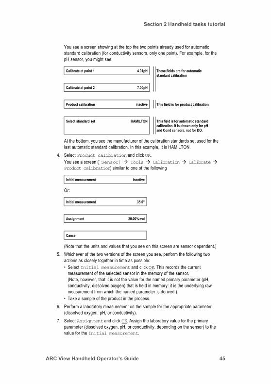
You see a screen showing at the top the two points already used for automatic standard calibration (for conductivity sensors, only one point). For example, for the pH sensor, you might see:
At the bottom, you see the manufacturer of the calibration standards set used for the last automatic standard calibration. In this example, it is HAMILTON.
4. Select Product calibration and click OK.You see a screen ([Sensor] Tools Calibration Calibrate Product calibration) similar to one of the following
Or:
(Note that the units and values that you see on this screen are sensor dependent.)5. Whichever of the two versions of the screen you see, perform the following two
actions as closely together in time as possible:• Select Initial measurement and click OK. This records the current
measurement of the selected sensor in the memory of the sensor.(Note, however, that it is not the value for the named primary parameter (pH, conductivity, dissolved oxygen) that is held in memory: it is the underlying raw measurement from which the named parameter is derived.)
• Take a sample of the product in the process.6. Perform a laboratory measurement on the sample for the appropriate parameter
(dissolved oxygen, pH, or conductivity).7. Select Assignment and click OK. Assign the laboratory value for the primary
parameter (dissolved oxygen, pH, or conductivity, depending on the sensor) to the value for the Initial measurement.
Calibrate at point 1 4.01pH These fields are for automatic standard calibration
Calibrate at point 2 7.00pH
Product calibration inactive This field is for product calibration
Select standard set HAMILTON This field is for automatic standard calibration. It is shown only for pH and Cond sensors, not for DO.
Initial measurement inactive
Initial measurement 35.0°
Assignment 20.00%-vol
Cancel
ARC View Handheld Operator’s Guide 45

Section 2 Handheld tasks tutorial
Product calibration is now active. This means that the value of the primary parameter now displayed on the Handheld for the sensor is continuously adjusted for greater accuracy with respect to the conditions of the process in which it was calibrated.
Section 2.4 Specialist tasksAs you know, the HAMILTON ARC System supports three kinds of operator: User, Administrator, and Specialist. Of these, the Specialist has the highest level of access. (If more information is required, read Section 1.5.2, ARC sensors: operator levels, on Page 19.)
In addition to his own tasks, the Specialist can perform:
• All User tasks.• All Administrator tasks.
NOTE: Be sure you are familiar with User and Administrator tasks before continuing in this section. (See Section 2.2, User tasks, on Page 37, and Section 2.3, Administrator tasks, on Page 40.)
Task 1 Setting the Specialist operator level
Introduction
To be able to perform Specialist tasks, an operator must first enter the Specialist password. This is explained in Actions immediately below.
Actions
1. If necessary, switch on the Handheld by pressing the Left Key and Right Key together for three seconds.
2. If the Handheld is already switched on, press the Left Key until you reach the top level of the interface, where you see the data-overview panels. (Figure 1.2, The ARC View Handheld showing top level of interface, pH sensor attached, on Page 11.)
3. Select the sensor with which you want to work.4. Click Tools.5. Select S for Specialist.6. Click OK, and enter the following password:
16021966
NOTE: • The password shown above is the factory default for the Specialist. This password can be changed using the ARC Sensor Configurator freeware.
• Every time the Handheld switches off automatically or is switched off manually, and every time an operator moves to the top level of the Handheld interface, the sensor defaults to the User operating mode. However, if when moving to the top level of the interface, the operator explicitly confirms that he or she wants to keep the password he or she has already entered, then the Handheld remembers the password. In this case, when the
46

Section 2 Handheld tasks tutorial
user clicks Tools to access functions that are password protected, he or she must only confirm (not re-enter) that password.
Task 2 Managing Handheld settings
Introduction
Adjusting Handheld settings is not a regular task. Of the settings listed here, it is necessary only to set the date and time, and to do that only with a new Handheld, when settings drift over time, or if there is a new battery fitted in the Handheld.
This task contains the following sub-tasks:
• Sub-Task 2.1, Adjusting date and time settings (necessary on occasion)• Sub-Task 2.2, Configuring screen and Handheld power settings (optional)• Sub-Task 2.3, Configuring ARC Handheld wireless settings (optional)
Sub-Task 2.1 Adjusting date and time settings
Introduction
The ARC Handheld displays the current time on the top left of its display (Figure 1.2, on Page 11). Although the Handheld does not display the current date, the date is used for STA files created by the ARC System (Task 4, Managing sensor STAtus profiles, on Page 51).
Actions
1. Select the ARC View Handheld panel on the top level of the Handheld’s interface. (This is shown on Figure 1.2, on Page 11.)
2. Click Tools.3. Enter the Specialist password as described in step 5 of Task 1, Setting the
Administrator operator level, on Page 41.4. Select Settings, and click OK.5. Select Set time, and click OK.
Set the time.6. Select Set date, and click OK.
Set the date.
NOTE: The time is displayed in 24-hour format. The date is displayed as DD-MM-YYYY. You cannot change these display formats.
Sub-Task 2.2 Configuring screen and Handheld power settings
Introduction
By default, the ARC Handheld switches off its screen after 5 minutes of no activity (after 5 minutes in which no manipulation of the Handheld takes place). Pressing any key switches the screen on again.
ARC View Handheld Operator’s Guide 47

Section 2 Handheld tasks tutorial
Similarly, by default, the ARC Handheld switches itself off completely after 20 minutes of no activity. You can switch it on in the normal way, by pressing the Left Key and the Right Key simultaneously for 3 seconds.
For both screen and Handheld automatic switch-off, you can configure the default switch-off times from 1 minute to infinity (never switch off) as documented below.
NOTE: • Screen switch-off does not switch off the Handheld or cause monitoring of sensors to stop. It only switches off the display.
• With both screen and Handheld switch-off settings, automatic switch-off takes place whether or not the Handheld is in the Dock.
Actions
1. Select the ARC View Handheld panel on the top level of the Handheld’s interface. (This is shown on Figure 1.2, on Page 11.)
2. Click Tools.3. Enter the Specialist password as described in step 5 of Task 1, Setting the
Administrator operator level, on Page 41.4. Select Settings, and click OK.5. Select Display settings, and click OK.
Set the length of time you want the screen to remain switched on. There are three options:• Enter the time in minutes.• Enter 000 if you want the screen to never switch off automatically.
6. Select Power settings, and click OK. Set the power settings as you did the display settings.
Sub-Task 2.3 Configuring ARC Handheld wireless settings
Introduction
ARC Handheld wireless settings govern wireless communication between the ARC Wi Sensor Adapter fitted to ARC sensors, and the ARC RF module in the Handheld.
ARC Handheld wireless settings have two configurations: Auto, and Always ON.
Auto is the default configuration: the handheld communicates over wire alone when placed in the Dock, and automatically switches to wireless mode when the Handheld is not in the Dock.
The alternative configuration is Always ON: wireless communication is always on, whether the Handheld is in the Dock or not. There can therefore be wireless communication with up to 30 sensors at all times, instead of wired communication with only one single sensor. Furthermore, the Handheld battery charges when in the Dock.
However, wired communication is not possible when Always ON is set. This means that any sensor connected by wire is not seen by the Handheld when it is on its Dock.
When the Handheld is switched off, it always resets to the default setting, Auto. To set Always ON, follow the instructions in Actions immediately below.
48
Section 2 Handheld tasks tutorial
Actions
1. Select the ARC View Handheld panel on the top level of the Handheld’s interface. (This is shown on Figure 1.2, on Page 11.)
2. Click Tools.3. Enter the Specialist password as described in step 5 of Task 1, Setting the
Administrator operator level, on Page 41.4. Select Settings, and click OK.5. Select Wireless settings, and click OK.
Select Auto or Always ON.
Task 3 Setting up a new sensor in an ARC system
As a Specialist, your job includes setting up and configuring elements of the ARC System. The most common task is adding or exchanging a sensor. This breaks down into the following sub-tasks:
• Sub-Task 3.1, Entering the Sensor ID• Sub-Task 3.2, Configuring the Modbus device address• Sub-Task 3.3, Configuring the Baud rate• Sub-Task 3.4, Configuring the analog interface• Sub-Task 3.5, Configuring a calibration
Sub-Task 3.1 Entering the Sensor ID
NOTE: • This sub-task is recommended when you add an ARC sensor to an ARC System.
• This sub-task concerns only the sensor’s digital interface.
Every sensor in an ARC System has a number of identifiers. These include:• The product name, for instance VISIFERM DO ARC.• The firmware version of the code included in the sensor.• The sensor’s part number.• The sensor’s serial number.• The sensor’s Modbus device address.
All operators can see these fields on [Sensor] View Sensor info.
Most of these identifiers are set in the factory, and cannot be changed. However, Specialists can change the Sensor ID. By default, this string contains the sensor’s part number followed by the sensor’s serial number. It is often helpful to enter a string in this field that uniquely identifies the sensor in the context of your ARC System environment. For example, the string Process C3 might enable other operators to quickly identify the sensor within your process environment.
NOTE: The Sensor ID is held in memory in the sensor. Every time you exchange a sensor for a new one, always check the ID Sensor string in the new sensor.
ARC View Handheld Operator’s Guide 49
Section 2 Handheld tasks tutorial
Specialists can change the Sensor ID on [Sensor] Tools Sensor info.
Sub-Task 3.2 Configuring the Modbus device address
NOTE: • This sub-task is mandatory when you add an ARC sensor to a digital PLC system.
• This sub-task concerns only the sensor’s digital interface.
An ARC sensor’s Modbus device address uniquely identifies an ARC sensor within a group of ARC sensors with respect to its digital communications with a digital PLC system. (However, it has no effect on communications with the ARC View Handheld, or with the connection to the 4-20 mA analog interface.)
It is recommended that every sensor in an ARC System have a unique Modbus device address. You can read more about Modbus device addresses in Section 1.5.5.2, Modbus device addresses, on Page 25.
Specialists can change the Modbus device address for a sensor on [Sensor] Tools Interface configuration Digital RS485.
Sub-Task 3.3 Configuring the Baud rate
NOTE: • This sub-task is recommended when you add an ARC sensor to a digital PLC system.
• This sub-task concerns only the sensor’s digital interface.
The Baud rate affects the wired connection made by an ARC sensor’s RS 485 Modbus digital interface. It has no influence on either wireless or analog connection of a sensor.
You can read more about Baud rates in Section 1.5.5.3, Baud rates, on Page 26.
You can find information about setting the Baud rate for a sensor on [Sensor] Tools Interface configuration Digital RS485.
Sub-Task 3.4 Configuring the analog interface
NOTE: • This sub-task is necessary when the sensor is connected to an analog PLC system.
• This sub-task concerns only the sensor’s analog interface or interfaces.
By configuring the ARC sensor’s analog interface, you make it able to map a measured value to the 4-20 mA standard interface. Configuration options for the analog interface are quite extensive, and are explained in detail in Section 1.5.6.3, Configuring the mode of the analog interfaces.
NOTE: If you are not using an analog connection it is recommended you switch off the analog interface.
Specialists can configure the analog interface of a sensor in [Sensor] Tools Interface configuration mA interface #1 [or #2, or mA/ECS-Interface].
50
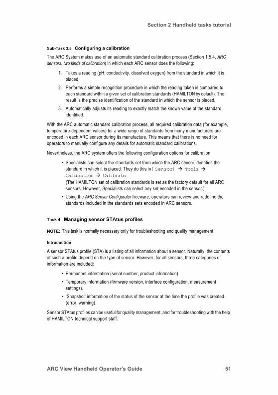
Section 2 Handheld tasks tutorial
Sub-Task 3.5 Configuring a calibration
The ARC System makes use of an automatic standard calibration process (Section 1.5.4, ARC sensors: two kinds of calibration) in which each ARC sensor does the following:
1. Takes a reading (pH, conductivity, dissolved oxygen) from the standard in which it is placed.
2. Performs a simple recognition procedure in which the reading taken is compared to each standard within a given set of calibration standards (HAMILTON by default). The result is the precise identification of the standard in which the sensor is placed.
3. Automatically adjusts its reading to exactly match the known value of the standard identified.
With the ARC automatic standard calibration process, all required calibration data (for example, temperature-dependent values) for a wide range of standards from many manufacturers are encoded in each ARC sensor during its manufacture. This means that there is no need for operators to manually configure any details for automatic standard calibrations.
Nevertheless, the ARC system offers the following configuration options for calibration:
• Specialists can select the standards set from which the ARC sensor identifies the standard in which it is placed. They do this in [Sensor] Tools Calibration Calibrate.(The HAMILTON set of calibration standards is set as the factory default for all ARC sensors. However, Specialists can select any set encoded in the sensor.)
• Using the ARC Sensor Configurator freeware, operators can review and redefine the standards included in the standards sets encoded in ARC sensors.
Task 4 Managing sensor STAtus profiles
NOTE: This task is normally necessary only for troubleshooting and quality management.
Introduction
A sensor STAtus profile (STA) is a listing of all information about a sensor. Naturally, the contents of such a profile depend on the type of sensor. However, for all sensors, three categories of information are included:
• Permanent information (serial number, product information).• Temporary information (firmware version, interface configuration, measurement
settings).• ‘Snapshot’ information of the status of the sensor at the time the profile was created
(error, warning).
Sensor STAtus profiles can be useful for quality management, and for troubleshooting with the help of HAMILTON technical support staff.
ARC View Handheld Operator’s Guide 51

Section 2 Handheld tasks tutorial
Sub-Task 4.1 Creating a sensor STAtus profile file
Introduction
You create a sensor STAtus (STA) profile file by copying information from a sensor to the Handheld. This creates a file that is held in memory in the Handheld. To do this, the sensor from which you wish to copy data must be connected to the Handheld in either wired or wireless mode.
There is space for 16 STA files on the Handheld. If you generate a 17th STA file, the first is automatically deleted. (This can be thought of as a file stack based on the ‘first in, first out’ principle.)
File name: STAxxxxx.txt, with xxxxx being a sequential number that serves to identify a file.
The typical size of STA files is 30 to 50 KB.
Actions
1. Select the sensor for which you want to make an STA file on the top level of the user interface, as shown in Figure 1.2, The ARC View Handheld showing top level of interface, pH sensor attached, on Page 11.
2. Enter the Specialist operator level as explained in Task 1, Setting the Specialist operator level, on Page 46.
3. Go to [Sensor] Tools Data management.4. Select Data transfer (Sensor to ARC View), and click OK.
An intermediary screen opens, with Sensor status profile selected.5. Click OK.
An STA file is created in the memory of the Handheld. Status screens keep you informed of progress.
Sub-Task 4.2 Downloading a sensor STAtus profile
Introduction
You now have one or more sensor STAtus profile (STA) files in the memory of the Handheld. Next, you must copy at least one of them to a USB memory stick.
Actions
1. Make sure that the Handheld is in its Dock, and that a memory stick is also inserted into its socket in the Dock.
2. Go to ARC View Handheld Tools Data management Data transfer (ARC View to USB device).An intermediary screen opens, with Sensor status profile selected.
3. Click OK.A second intermediary screen opens displaying a list of available STA files.
4. Select the file you wish to download to the memory stick inserted in the Dock, and click OK.
52

Section 2 Handheld tasks tutorial
5. A final intermediary screen opens, giving a brief overview of the file you have selected. Click OK to download the file to the memory stick, or, if you have selected the wrong file, click the Left Key to return to the list, and reselect.
Sub-Task 4.3 Reading a sensor STAtus profile file
Reading a sensor STAtus profile (STA) file is easy: you can view or print it from any application that can display ASCII text (Excel is ideal, but Notepad or MS Word also work well).
For details of the fields in the STA file, see Appendix C, Sensor STAtus profile.
Task 5 Managing trace files
Sub-Task 5.1 Creating a trace file
With ARC View Handheld, you can record the measurement data of a single sensor in a trace file.
Whenever you view the screen Graph/data log in Specialist mode ([Sensor] Tools Measurement Graph/data log), a trace file will be created. The name of the file will be displayed in the title, with the name DATxxxxx.txt (xxxxx is a sequential number). As soon as you leave the Graph/data log screen, the data recording will be stopped. When you access the screen again, a new trace file will be created.
If the communication to the sensor is interrupted, the data points of the graph will display the last valid measurement values in red. In the trace file, only the time stamps for the measurement values will be recorded, but no sensor measurement values.
NOTE: While data logging is active, the Handheld will not be turned off automatically. Only the display will be disabled in case of inactivity.
NOTE: If the memory of the Handheld is full, the oldest file will be overwritten by the new one. ARC View Handheld can store at most 16 files per file type. Maximum size for a single file is 256 kb, this corresponds to 8.3 hours of measurement data recording.
Sub-Task 5.2 Downloading a trace file
1. Place the Handheld on the ARC View Dock, and connect an USB memory stick to the Dock.
2. Turn on the Handeld, if it is not already turned on. Go to ARC View Handheld Tools Data management Data transfer (ARC View to USB device). Select Graph/Data log. A list of available trace files will be displayed.
3. Select a file, and click OK. You will reach a screen with information about the file. Click OK again, and the selected file will be downloaded to the memory stick.
4. Connect the memory stick to a computer.5. You can now open the file with a texteditor or table editor.
ARC View Handheld Operator’s Guide 53

Section 2 Handheld tasks tutorial
Sub-Task 5.3 Interpreting a trace file
Characteristics of a trace file:
• File name: DATxxxxx.txt, with xxxxx being a sequential number that serves to identify a file.
NOTE: If there are files created from various Handhelds, there may be several with the same names.
• File properties: Standard ASCII text file, text blocks separated by tabs.
54

Section 2 Handheld tasks tutorial
Example trace file
Task 6 Managing Sensor Configuration Files
Introduction
Sensor Configuration Files are sequential scripts of sensor commands used by ARC View Handheld to configure sensors. They can be programmed manually at a Computer, copied to a Handheld and from there to a specific sensor, or they can be generated directly from the configuration of an existing sensor.
*** Measurement data log file ***Filename: DAT00001
ARC VIEW HPart number 242128/03 Serial number 000100 RF address 59568134Firmware version VIHMS024Date Time 2010-11-31 14:24
ARC Wi sensor adapterPart number 242170/00Serial number 0327646RF address 59560146Firmware version WI0MS006
Sensor infoFirmware version user end
EPHUM011
Firmware date user end 2010-04-23Productname Polilyte PlusPart number 242111/00Workorder number 1388539Workorder date 2010-02-22Serial number 1201Sensor ID EPH02
Date Time pH / pH T / °C2010-11-31 14:24:05 6.191 26.4102010-11-31 14:24:09 6.191 26.4102010-11-31 14:24:13 6.191 26.4102010-11-31 14:24:17 6.191 26.4102010-11-31 14:24:21 6.191 26.4102010-11-31 14:24:25 6.191 26.4112010-11-31 14:24:29 6.191 26.4112010-11-31 14:24:33 6.191 26.4112010-11-31 14:24:37 6.191 26.4102010-11-31 14:24:41 6.191 26.4112010-11-31 14:24:45 6.191 26.411
Table 2.3 Example of a trace file: ASCII text imported into a text publishing software and convertedinto a table. It contains the file name in the title, sensor information in the header and measurement data with time stamps in the body.
ARC View Handheld Operator’s Guide 55
Section 2 Handheld tasks tutorial
NOTE: Sensor Configuration Files are a powerful tool. Erroneous use may lead to corrupted sensor configuration and malfunction in the application. Thoroughly check newly configured sensors before using them in your application! If they do not work as intended, review and correct the complete sensor configuration manually.
NOTE: The name of the Sensor Configuration File must have the file extension .pro, and it must consist of exactly eight (8) numbers and letters excluding the extension.
Sub-Task 6.1 Creating a Sensor Configuration File from a sensor
1. Got to [Sensor] Tools Data management Data transfer (Sensor to ARC View) Sensor configuration, and click OK.
2. ARC View Handheld will generate and store the Sensor Configuration File in its internal memory.
3. If you want to download the Sensor Configuration File to a computer, go to ARC View Handheld Tools Data management Data transfer (ARC View to USB device). Select Sensor configuration and click OK. Select one of the listed files and click OK to download it to the memory stick.
NOTE: If you create a Sensor Configuration File from an existing sensor, the device address, baud rate and passwords will not be included.
Sub-Task 6.2 Manually creating a Sensor Configuration File using a computer
NOTE: Only work with Sensor Configuration Files after you have made yourself familiar with the syntax. You will find information about the sensor functionality and command structure in the ARC Programmer’s Manuals of the respective ARC sensors. See Appendix A.5, HAMILTON ARC System documents, on Page 137, for documents with information about the sensor specific programming options.
Create the Sensor Configuration File with a text editor as plain text ASCII file. The name of the Sensor Configuration File must have the file extension .pro, and it must consist of exactly eight (8) numbers or letters excluding the extension.
Structure of the Sensor Configuration File
• General criteria• Data fields are separated by semicolons ;• Contains a header with compatibility criteria• Contains a command section with the commands applied to the sensor
• Header• Must contain a line defining the HAMILTON part numbers of the sensors for which
the Configuration File is valid. It must start with the keyword PART. Example: PART;242450-01;242452-02;242453-01
• Can contain a line defining the firmware versions for which the Configuration File is valid. It must start with the keyword FIRMWARE.Example: FIRMWARE;ODOUM038;ODOUM037
56
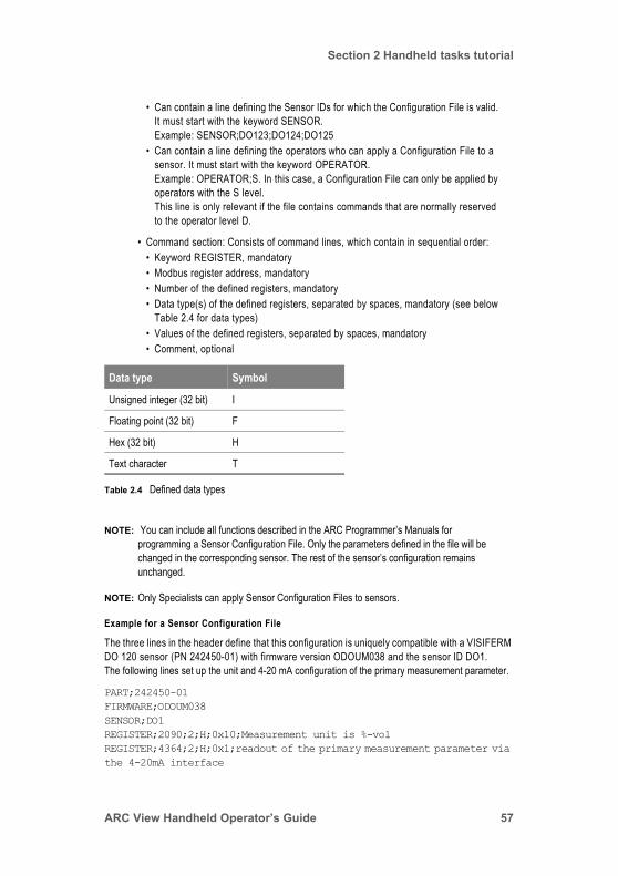
Section 2 Handheld tasks tutorial
• Can contain a line defining the Sensor IDs for which the Configuration File is valid. It must start with the keyword SENSOR.Example: SENSOR;DO123;DO124;DO125
• Can contain a line defining the operators who can apply a Configuration File to a sensor. It must start with the keyword OPERATOR.Example: OPERATOR;S. In this case, a Configuration File can only be applied by operators with the S level.This line is only relevant if the file contains commands that are normally reserved to the operator level D.
• Command section: Consists of command lines, which contain in sequential order:• Keyword REGISTER, mandatory• Modbus register address, mandatory• Number of the defined registers, mandatory• Data type(s) of the defined registers, separated by spaces, mandatory (see below
Table 2.4 for data types)• Values of the defined registers, separated by spaces, mandatory• Comment, optional
NOTE: You can include all functions described in the ARC Programmer’s Manuals for programming a Sensor Configuration File. Only the parameters defined in the file will be changed in the corresponding sensor. The rest of the sensor’s configuration remains unchanged.
NOTE: Only Specialists can apply Sensor Configuration Files to sensors.
Example for a Sensor Configuration File
The three lines in the header define that this configuration is uniquely compatible with a VISIFERM DO 120 sensor (PN 242450-01) with firmware version ODOUM038 and the sensor ID DO1.The following lines set up the unit and 4-20 mA configuration of the primary measurement parameter.
PART;242450-01FIRMWARE;ODOUM038SENSOR;DO1REGISTER;2090;2;H;0x10;Measurement unit is %-volREGISTER;4364;2;H;0x1;readout of the primary measurement parameter via the 4-20mA interface
Data type Symbol
Unsigned integer (32 bit) I
Floating point (32 bit) F
Hex (32 bit) H
Text character T
Table 2.4 Defined data types
ARC View Handheld Operator’s Guide 57
Section 2 Handheld tasks tutorial
REGISTER;4360;2;H;0x2;linear configuration 4-20mA linearREGISTER;4378;6;F F F;0 62.85 0;Konfiguration 4-20mA (min,max,mid value)
Sub-Task 6.3 Loading a Sensor Configuration File onto a sensor
Loading the Sensor Configuration File from a USB memory stick to ARC View Handheld:
1. Place ARC View Handheld in the Dock, and connect a memory stick containing the Sensor Configuration File.
2. Go to ARC View Handheld Tools Data management Data transfer (USB device to ARC View).
3. Select the Sensor Configuration File and click Ok.4. You will be informed about the data transfer status.
Loading the Sensor Configuration File from the Handheld to the sensor:
1. Go to [Sensor] Tools Data management Data transfer (ARC View to sensor) Configuration Profile, and click OK.
2. Select your file, and click OK.3. The parameters defined in the Sensor Configuration File will be applied to the sensor.
58
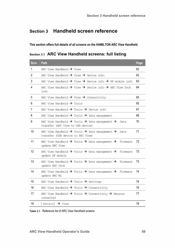
Section 3 Handheld screen reference
Section 3 Handheld screen reference
This section offers full details of all screens on the HAMILTON ARC View Handheld.
Section 3.1 ARC View Handheld screens: full listing
Scrn Path Page
1 ARC View Handheld View 62
2 ARC View Handheld View Device info 62
3 ARC View Handheld View Device info RF module info 63
4 ARC View Handheld View Device info ARC View Dock info
64
5 ARC View Handheld View Connectivity 65
6 ARC View Handheld Tools 65
7 ARC View Handheld Tools Device info 67
8 ARC View Handheld Tools Data management 68
9 ARC View Handheld Tools Data management Data transfer (ARC View to USB device)
70
10 ARC View Handheld Tools Data management Data transfer (USB device to ARC View)
71
11 ARC View Handheld Tools Data management Firmware update ARC View
72
12 ARC View Handheld Tools Data management Firmware update RF module
73
13 ARC View Handheld Tools Data management Firmware update ARC Dock
73
14 ARC View Handheld Tools Data management Firmware update ARC Wi
74
15 ARC View Handheld Tools Settings 74
16 ARC View Handheld Tools Connectivity 76
17 ARC View Handheld Tools Connectivity Sensors connected
77
18 [Sensor] View 78
Table 3.1 Reference list of ARC View Handheld screens
ARC View Handheld Operator’s Guide 59
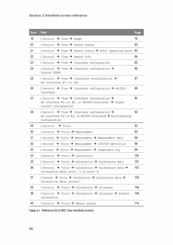
Section 3 Handheld screen reference
19 [Sensor] View Graph 79
20 [Sensor] View Sensor status 80
21 [Sensor] View Sensor status Total operating hours 83
22 [Sensor] View Sensor info 84
23 [Sensor] View Interface configuration 85
24 [Sensor] View Interface configuration Digital RS485
86
25 [Sensor] View Interface configuration mA interface #1 [or #2]
87
26 [Sensor] View Interface configuration mA/ECS-Interface
88
27 [Sensor] View Interface configuration mA interface #1 [or #2, or mA/ECS-Interface] Output current configuration
90
28 [Sensor] View Interface configuration mA interface #1 [or #2, or mA/ECS-Interface] Error/warning configuration
92
29 [Sensor] Tools 93
30 [Sensor] Tools Measurement 95
31 [Sensor] Tools Measurement Measurement data 98
32 [Sensor] Tools Measurement CIP/SIP definition 98
33 [Sensor] Tools Measurement Graph/data log 99
34 [Sensor] Tools Calibration 100
35 [Sensor] Tools Calibration Calibration data 101
36 [Sensor] Tools Calibration Calibration data Calibration data: point 1 [or point 2]
103
37 [Sensor] Tools Calibration Calibration data Calibration data: product
105
38 [Sensor] Tools Calibration Calibrate 106
39 [Sensor] Tools Calibration Calibrate Product calibration
108
40 [Sensor] Tools Sensor status 110
Scrn Path Page
Table 3.1 Reference list of ARC View Handheld screens
60

Section 3 Handheld screen reference
Section 3.2 ARC View Handheld screens: full details
Screen 0: Highest level of Handheld screen interface
Screen name: None.Purpose: Enables selection of the Handheld itself or of a connected sensor, for
monitoring or configuration.Comments: This screen is fully explained in Figure 1.2, The ARC View Handheld showing
top level of interface, pH sensor attached, on Page 11.
41 [Sensor] Tools Interface configuration 110
42 [Sensor] Tools Interface configuration Digital RS485
112
43 [Sensor] Tools Interface configuration mA interface #1 [or #2, or mA/ECS-Interface]
113
44 [Sensor] Tools Interface configuration mA interface #1 [or #2, or mA/ECS-Interface] Interface mode
114
45 [Sensor] Tools Interface configuration mA interface #1 [or #2, or mA/ECS-Interface] Output current configuration
115
46 [Sensor] Tools Interface configuration mA interface #1 [or #2] Error/warning configuration
118
47 [Sensor] Tools Data management 120
48 [Sensor] Tools Sensor info 122
49 [Sensor] Tools Sensor info ARC Wi info 123
Scrn Path Page
Table 3.1 Reference list of ARC View Handheld screens
ARC View Handheld Operator’s Guide 61
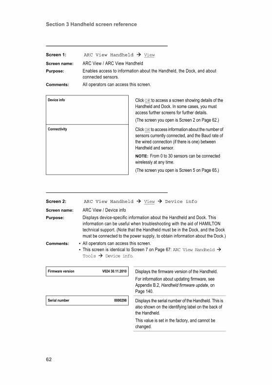
Section 3 Handheld screen reference
Screen 1: ARC View Handheld View
Screen name: ARC View / ARC View HandheldPurpose: Enables access to information about the Handheld, the Dock, and about
connected sensors.Comments: All operators can access this screen.
Screen 2: ARC View Handheld View Device info
Screen name: ARC View / Device infoPurpose: Displays device-specific information about the Handheld and Dock. This
information can be useful when troubleshooting with the aid of HAMILTON technical support. (Note that the Handheld must be in the Dock, and the Dock must be connected to the power supply, to obtain information about the Dock.)
Comments: • All operators can access this screen.• This screen is identical to Screen 7 on Page 67: ARC View Handheld Tools Device info.
Device info Click OK to access a screen showing details of the Handheld and Dock. In some cases, you must access further screens for further details.(The screen you open is Screen 2 on Page 62.)
Connectivity Click OK to access information about the number of sensors currently connected, and the Baud rate of the wired connection (if there is one) between Handheld and sensor.NOTE: From 0 to 30 sensors can be connected wirelessly at any time.(The screen you open is Screen 5 on Page 65.)
Firmware version V024 30.11.2010 Displays the firmware version of the Handheld.For information about updating firmware, see Appendix B.2, Handheld firmware update, on Page 140.
Serial number 0000298 Displays the serial number of the Handheld. This is also shown on the identifying label on the back of the Handheld. This value is set in the factory, and cannot be changed.
62

Section 3 Handheld screen reference
Screen 3: ARC View Handheld View Device info RF module info
Screen name: ARC View / RF modul infoPurpose: Displays device-specific information about the radio frequency module in the
Handheld. This information can be useful when troubleshooting with the aid of HAMILTON technical support.
Comments: All operators can access this screen.
Workorder number 2091325 / 399 Displays the workorder number of the Handheld. This is also shown on the identifying label on the back of the Handheld.This number can be useful in tracing faulty units to production runs. The value is set in the factory, and cannot be changed.
Part number 242128 Displays the part number of the Handheld. This is also shown on the identifying label on the back of the Handheld.
Productname ARC View Handheld Displays the full product name of the Handheld.
Serial number PCB 98273485 Displays the serial number of the printed circuit board in the Handheld. This number could be useful in troubleshooting with the help of technical support.
RF module info Click OK to access a a screen showing details of the radio frequency module in the Handheld.(The screen you open is Screen 3 on Page 63.)
ARC View Dock info NOTE: This field is available only when the Handheld is in the Dock, and the Dock is connected to the power supply.Click OK to access a screen showing details of the Dock.(The screen you open is Screen 4 on Page 64.)
This field is availableonly when the
Handheld is in theDock, and the Dock is
connected to thepower supply.
RF module firmware version VRFMS006 Displays the version of the firmware currently loaded on the printed circuit board of the Handheld. For information about updating firmware, see Appendix B.3, Handheld RF Module firmware update, on Page 141.
ARC View Handheld Operator’s Guide 63
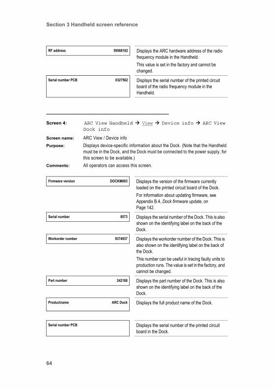
Section 3 Handheld screen reference
Screen 4: ARC View Handheld View Device info ARC View Dock info
Screen name: ARC View / Device infoPurpose: Displays device-specific information about the Dock. (Note that the Handheld
must be in the Dock, and the Dock must be connected to the power supply, for this screen to be available.)
Comments: All operators can access this screen.
RF address 59568162 Displays the ARC hardware address of the radio frequency module in the Handheld.This value is set in the factory and cannot be changed.
Serial number PCB 0327562 Displays the serial number of the printed circuit board of the radio frequency module in the Handheld.
Firmware version DOCKM003 Displays the version of the firmware currently loaded on the printed circuit board of the Dock. For information about updating firmware, see Appendix B.4, Dock firmware update, on Page 142.
Serial number 8573 Displays the serial number of the Dock. This is also shown on the identifying label on the back of the Dock.
Workorder number 9374937 Displays the workorder number of the Dock. This is also shown on the identifying label on the back of the Dock.This number can be useful in tracing faulty units to production runs. The value is set in the factory, and cannot be changed.
Part number 242168 Displays the part number of the Dock. This is also shown on the identifying label on the back of the Dock.
Productname ARC Dock Displays the full product name of the Dock.
Serial number PCB Displays the serial number of the printed circuit board in the Dock.
64

Section 3 Handheld screen reference
Screen 5: ARC View Handheld View Connectivity
Screen name: ARC View / ConnectivityPurpose: Displays information about the number of sensors connected to the Handheld
and the Baud rate of the connections.Comments: • All operators can access this screen.
• The total number of Handheld/sensor connections possible at any time is 30.• Connections can be wired or wireless, depending on whether the Handheld is
in its Dock (wired) or not in its Dock (when connections automatically become radio connections).
• All Handheld/sensor connections take place through the digital interface.
Screen 6: ARC View Handheld Tools
Screen name: ARC View / ARC View HandheldPurpose: Enables access to screens offering information and configuration settings for
the Handheld and Dock, and firmware updates for the Handheld, Dock, sensors, and ARC Wi Sensor Adapters.
Comments: The Data management and Settings parts of this screen are password-protected. Only Specialists can see them.
Sensors connected 1 Displays the number of sensors (1 to 30) currently connected to the Handheld.
Baud rate 19200 Displays the Baud rate of the wired connection between an ARC sensor’s RS485 Modbus digital interface, and the Handheld.(Specialists can change the Baud rate in Screen 16 on Page 76.)NOTE: For more information about Baud rates, see Section 1.5.5.3, Baud rates.
This field is shown onlywhen a wired connection
is active
Device info Click OK to access a screen showing details of the Handheld and Dock. In some cases, you must access further screens for further details.(The screen you open is Screen 7 on Page 67.)
ARC View Handheld Operator’s Guide 65
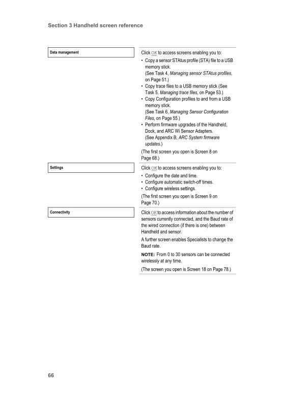
Section 3 Handheld screen reference
Data management Click OK to access screens enabling you to:• Copy a sensor STAtus profile (STA) file to a USB
memory stick.(See Task 4, Managing sensor STAtus profiles, on Page 51.)
• Copy trace files to a USB memory stick (See Task 5, Managing trace files, on Page 53.)
• Copy Configuration profiles to and from a USB memory stick.(See Task 6, Managing Sensor Configuration Files, on Page 55.)
• Perform firmware upgrades of the Handheld, Dock, and ARC Wi Sensor Adapters. (See Appendix B, ARC System firmware updates.)
(The first screen you open is Screen 8 on Page 68.)
Settings Click OK to access screens enabling you to:• Configure the date and time.• Configure automatic switch-off times.• Configure wireless settings.(The first screen you open is Screen 9 on Page 70.)
Connectivity Click OK to access information about the number of sensors currently connected, and the Baud rate of the wired connection (if there is one) between Handheld and sensor.A further screen enables Specialists to change the Baud rate.NOTE: From 0 to 30 sensors can be connected wirelessly at any time.(The screen you open is Screen 18 on Page 78.)
66

Section 3 Handheld screen reference
Screen 7: ARC View Handheld Tools Device info
Screen name: ARC View / Device infoPurpose: Displays device-specific information about the Handheld and Dock. This
information can be useful when troubleshooting with the aid of HAMILTON technical support. (Note that the Handheld must be in the Dock, and the Dock must be connected to the power supply, to obtain information about the Dock.)
Comments: • All operators can access this screen.• This screen is identical to Screen 2 on Page 62: ARC View Handheld View Device info.
ARC View Handheld Operator’s Guide 67
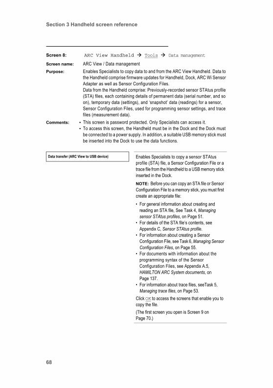
Section 3 Handheld screen reference
Screen 8: ARC View Handheld Tools Data management
Screen name: ARC View / Data managementPurpose: Enables Specialists to copy data to and from the ARC View Handheld. Data to
the Handheld comprise firmware updates for Handheld, Dock, ARC Wi Sensor Adapter as well as Sensor Configuration Files. Data from the Handheld comprise: Previously-recorded sensor STAtus profile (STA) files, each containing details of permanent data (serial number, and so on), temporary data (settings), and ‘snapshot’ data (readings) for a sensor, Sensor Configuration Files, used for programming sensor settings, and trace files (measurement data).
Comments: • This screen is password protected. Only Specialists can access it.• To access this screen, the Handheld must be in the Dock and the Dock must
be connected to a power supply. In addition, a suitable USB memory stick must be inserted into the Dock to use the data functions.
Data transfer (ARC View to USB device) Enables Specialists to copy a sensor STAtus profile (STA) file, a Sensor Configuration File or a trace file from the Handheld to a USB memory stick inserted in the Dock.NOTE: Before you can copy an STA file or Sensor Configuration File to a memory stick, you must first create an appropriate file:• For general information about creating and
reading an STA file, See Task 4, Managing sensor STAtus profiles, on Page 51.
• For details of the STA file’s contents, see Appendix C, Sensor STAtus profile.
• For information about creating a Sensor Configuration File, see Task 6, Managing Sensor Configuration Files, on Page 55.
• For documents with information about the programming syntax of the Sensor Configuration Files, see Appendix A.5, HAMILTON ARC System documents, on Page 137.
• For information about trace files, seeTask 5, Managing trace files, on Page 53.
Click OK to access the screens that enable you to copy the file.(The first screen you open is Screen 9 on Page 70.)
68

Section 3 Handheld screen reference
Data transfer (USB device to ARC View) Enables Specialists to copy language files and Sensor Configuration Files from a USB memory stick to the Handheld.For information about Sensor Configuration Files, see Task 6, Managing Sensor Configuration Files, on Page 55.
Firmware update ARC View Enables Specialists to update the firmware in the Handheld. (This firmware contains the screens that you see on the Handheld.)NOTE: Before updating the Handheld, read Appendix B.2, Handheld firmware update, on Page 140.Click OK to access the screens that enable you to perform this update.(The first screen you open is Screen 11 on Page 72.)
Firmware update RF module Enables Specialists to update the firmware in the Handheld’s radio frequency module.NOTE: Before updating the Handheld’s RF module, read Appendix B.3, Handheld RF Module firmware update, on Page 141.Click OK to access the screens that enable you to perform this update.(The first screen you open is Screen 12 on Page 73.)
Firmware update ARC Dock Enables Specialists to update the Dock firmware.NOTE: Before updating the Handheld’s Dock, read Appendix B.4, Dock firmware update, on Page 142.Click OK to access the screens that enable you to perform this update.(The first screen you open is Screen 13 on Page 73.)
ARC View Handheld Operator’s Guide 69
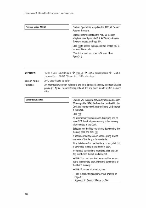
Section 3 Handheld screen reference
Screen 9: ARC View Handheld Tools Data management Data transfer (ARC View to USB device)
Screen name: ARC View / Data transferPurpose: An intermediary screen helping to enable a Specialist to copy a sensor STAtus
profile (STA) file, Sensor Configuration Files and trace files to a USB memory stick.
Firmware update ARC Wi Enables Specialists to update the ARC Wi Sensor Adapter firmware.NOTE: Before updating the ARC Wi Sensor adapters, read Appendix B.6, Wi Sensor Adapter firmware update, on Page 144.Click OK to access the screens that enable you to perform this update.(The first screen you open is Screen 14 on Page 74.)
Sensor status profile Enables you to copy a previously-recorded sensor STAtus profile (STA) file from the Handheld in the Dock to a memory stick inserted in the USB socket in the Dock.Click OK.An intermediary screen opens displaying one or more STA files that you can copy to the memory stick inserted in the Dock. Select one of the files you wish to download to the memory stick and click OK.A final intermediary screen opens, giving a brief overview of the file you have selected. If the details confirm that the file is correct, click OK to download the file to the memory stick.If you have selected the wrong file, click the Left Key to return to the list, and reselect.NOTE: You can download as many files as you like to the memory stick, within the constraints of the stick’s memory.NOTE: For more information, see:• Task 4, Managing sensor STAtus profiles, on
Page 51.• Appendix C, Sensor STAtus profile.
70

Section 3 Handheld screen reference
Screen 10: ARC View Handheld Tools Data management Data transfer (USB device to ARC View)
Screen name: ARC View / Data transferPurpose: An intermediary screen enabling a Specialist to copy additional language files
and Sensor Configuration Files to the Handheld.
Configuration profile Enables you to copy a Sensor Configuration File from the Handheld to a memory stick inserted in the USB socket of the Dock.For the further proceeding, please see the description for sensor STAtus profiles above.NOTE: For information about Sensor Configuration Files, see Task 6, Managing Sensor Configuration Files, on Page 55.
Graph/data log Enables you to copy a trace file from the Handheld to a memory stick inserted in the USB socket of the Dock.For the further proceeding, please see the description for sensor STAtus profiles above.NOTE: For information about trace files, see Task 5, Managing trace files, on Page 53.
Optional languages Enables you to copy a language file from a memory stick inserted in the USB socket in the Dock to a Handheld.Click OK.An intermediary screen opens displaying one or more language files on the memory stick. Select the file you wish to copy to the Handheld and click OK.
ARC View Handheld Operator’s Guide 71

Section 3 Handheld screen reference
Screen 11: ARC View Handheld Tools Data management Firmware update ARC View
Screen name: ARC View / Firmware update ARC ViewPurpose: An intermediary screen enabling a Specialist to update the firmware on the
Handheld.
Configuration profile Enables you to copy a Sensor Configuration File from a memory stick inserted in the USB socket of the Dock to a Handheld.Click OK.An intermediary screen opens displaying one or more Sensor Configuration Files available on the memory stick. Select one of the files you wish to copy to the Handheld and click OK.NOTE: ARC View Handheld can store at most 16 files per file type. Maximum size for a single file is 256 kb.NOTE: For information about Sensor Configuration Files, see Task 6, Managing Sensor Configuration Files, on Page 55.
VHMS024 Select the Handheld firmware update file you require (typically, there is only one) and click OK.NOTE: Handheld firmware files have the suffix .mot, but suffixes are not shown on the Handheld screen.
72

Section 3 Handheld screen reference
Screen 12: ARC View Handheld Tools Data management Firmware update RF module
Screen name: ARC View / Firmware update RF modulePurpose: An intermediary screen helping to enable a Specialist to update the firmware
on the Handheld’s RF module.
Screen 13: ARC View Handheld Tools Data management Firmware update ARC Dock
Screen name: ARC View / Firmware update ARC DockPurpose: An intermediary screen helping to enable a Specialist to update the firmware
in the Dock.
VRFMS006 Select the Handheld RF module firmware update file you require (typically, there is only one) and click OK.NOTE: Handheld RF module firmware files have the suffix .bin, but suffixes are not shown on the Handheld screen.
DOCKM004 Select the Dock firmware update file you require (typically, there is only one) and click OK.NOTE: Dock firmware files have the suffix .hex, but suffixes are not shown on the Handheld screen.
ARC View Handheld Operator’s Guide 73

Section 3 Handheld screen reference
Screen 14: ARC View Handheld Tools Data management Firmware update ARC Wi
Screen name: ARC View / Firmware update ARC WiPurpose: An intermediary screen helping to enable a Specialist to update the ARC Wi
Sensor Adapter firmware.
Screen 15: ARC View Handheld Tools Settings
Screen name: ARC View / SettingsPurpose: Enables a Specialist to set the current time on the real-time clock shown on
the front screen of the Handheld. In addition, the current date can be set. (Both date and time are used to stamp files created by the ARC System.) Also, settings for display-on time, power-on time, and wireless connection can be made. Furthermore, passwords for operator level Administrator (A) and Specialist (S) can be changed. Finally, factory settings can be reset.
Comments: This screen is password protected. Only Specialists can access it.
WI0MS006 Select the ARC Wi Sensor Adapter firmware update file you require (typically, there is only one) and click OK.NOTE: ARC Wi Sensor Adapter firmware files have the suffix .bin, but suffixes are not shown on the Handheld screen.
Set time Click OK to access a screen on which you can set the time for the real-time clock shown on the front screen of the Handheld (Figure 1.2, on Page 11). (This screen is very simple and intuitive, and is not documented separately below.)Note that the time is in 24-hour format.
Set date Click OK to access a screen on which you can set the date. (This screen is very simple and intuitive, and is not documented separately below.)The date is not displayed on the front screen of the Handheld, but is important for marking generated files, such as the sensor STAtus profile (STA) file.
74
Section 3 Handheld screen reference
Display settings Click OK to access a screen on which you can set the length of time in minutes that the Handheld display stays illuminated between key presses. (This screen is very simple and intuitive, and is not documented separately below.)If you enter a value of 000, the screen never switches off. If you enter a value of 999, the screen switches off after a default time of 5 minutes.NOTE: This setting does not switch off the Handheld or cause monitoring of sensors to stop. It only switches off the display.
Power settings Click OK to access a screen on which you can set the length of time in minutes that the Handheld remains switched on between key presses. (This screen is very simple and intuitive, and is not documented separately below.)If you enter a value of 000, the Handheld never switches off. If you enter a value of 999, the Handheld switches off after a default time of 20 minutes.
Wireless settings Click OK to access a screen on which you can select one of the following:• Auto
Default mode. The ARC wireless system between the ARC Wi Sensor Adapters on the sensors, and the radio frequency module in the Handheld switches on automatically when the Handheld is removed from the Dock.
• Always ON: The ARC wireless system is always switched on, even when the Handheld is in its Dock. Operators can work in wireless mode with the Handheld in the Dock, and can see all sensors that are wirelessly connected to the Handheld.
ARC View Handheld Operator’s Guide 75
Section 3 Handheld screen reference
Screen 16: ARC View Handheld Tools Connectivity
Screen name: ARV View / ConnectivityPurpose: Enables all operators to see the number of sensors connected, and the Baud
rate of the connections. Specialists can also change the Baud rate.Comments: This screen is the same as Screen 3 on Page 63: ARC View Handheld
View Device info RF module info, except that it enables Specialists to change the Baud rate of Handheld.
Change password Enables you to change the password for operator level Administrator (A) or Specialist (S).Click OK to access a screen on which you can select one of the following:• Change password for A:
Click OK for a screen for entering the new password. You will be asked to enter the password a second time for confirmation.
• Change password for S: Click OK for a screen for entering the new password. You will be asked to enter the password a second time for confirmation.
Restore factory settings Enables you to set the ARC View Handheld back to factory settings.Click OK to access a screen on which you confirm that the configuration should be reset to factory settings.NOTE: If you restore the factory default settings, all settings you you customized on your device will be lost.For more information about restoring the factory settings, see Section 4.6, Restore Factory Settings, on Page 132.
Sensors connected 1 Displays the number of sensors (1 to 30) currently connected to the Handheld.Click OK to access a screen which enables you to manage a list of sensor favorites.(The screen you open is Screen 17 on Page 77.)
76

Section 3 Handheld screen reference
Screen 17: ARC View Handheld Tools Connectivity Sensors connected
Screen name: ARC View / Connected sensorsPurpose: Enables all operators to see the number of monitored sensors, and the Baud
rate of the ARC View Handheld wired connection. Specialists can also change the Baud rate.
Comments: If you select this path: ARC View Handheld View Connectivity Sensors connected, you will receive the message operator level not valid.
Baud rate 19200 Displays the Baud rate of the wired connection between an ARC sensor’s RS485 Modbus digital interface, and the Handheld.Click OK to access a screen enabling you to change the Baud rate. (This screen is very simple and intuitive, and is not documented separately below.)NOTE: For more information about Baud rates and their effect on the ARC View System, see Section 1.5.5.3, Baud rates.
This field is shown onlywhen a wired connection
is active
Select favorites Click OK to access a screen on which you can select favorites from a list of sensors monitored by the Handheld. The favorites will be permanently stored in the memory of the Handheld. The corresponding sensors will be presented at the top level of the Handeheld’s interface.
Arrange favorites Click OK to access a screen where you can sort the favorites list. To do this, select the sensor of interest and click OK. Move the cursor to a new position and click OK. The two positions will be exchanged.
Delete sensor list Click OK to access a screen that allows you to delete the sensor favorites. Click OK on this screen to delete the sensor list, or the left button to return to the previous screen.NOTE: The connection between sensors and handheld is lost after deleting the favorites. Return to the top level of the interface to reestablish the connections to sensors available in your network.
ARC View Handheld Operator’s Guide 77
Section 3 Handheld screen reference
Screen 18: [Sensor] View
Screen name: [Sensor type] / [Sensor ID] / ViewPurpose: Enables all operators to access many kinds of information about a sensor with
the aid of further screens.Comments: All operators can access this screen.
Graph Click OK to access a real-time graph tracing readings of the sensor now selected on the Handheld. (The screen you open is Screen 19 on Page 79.)
Sensor status Click OK to access full details of the current operating status of the sensor now selected on the Handheld. (The screen you open is Screen 20 on Page 80.)
Sensor info Click OK to access full factory identification details of the sensor now selected on the Handheld. (The screen you open is Screen 22 on Page 84.)
Interface configuration Click OK to access further screens offering full details of:• The digital RS485 configuration• The analog 4–20 mA configuration(s)of the sensor now selected on the Handheld.(The first screen you open is Screen 23 on Page 85.)
78
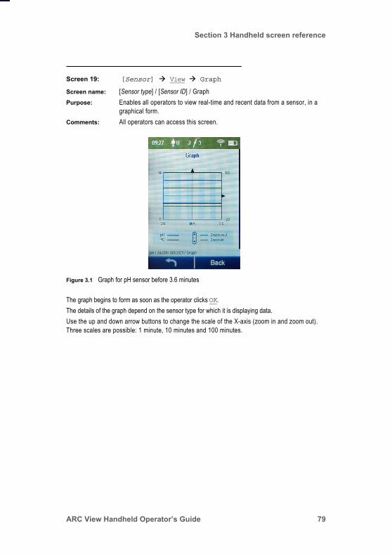
Section 3 Handheld screen reference
Screen 19: [Sensor] View Graph
Screen name: [Sensor type] / [Sensor ID] / GraphPurpose: Enables all operators to view real-time and recent data from a sensor, in a
graphical form.Comments: All operators can access this screen.
The graph begins to form as soon as the operator clicks OK.The details of the graph depend on the sensor type for which it is displaying data.Use the up and down arrow buttons to change the scale of the X-axis (zoom in and zoom out). Three scales are possible: 1 minute, 10 minutes and 100 minutes.
Figure 3.1 Graph for pH sensor before 3.6 minutes
ARC View Handheld Operator’s Guide 79
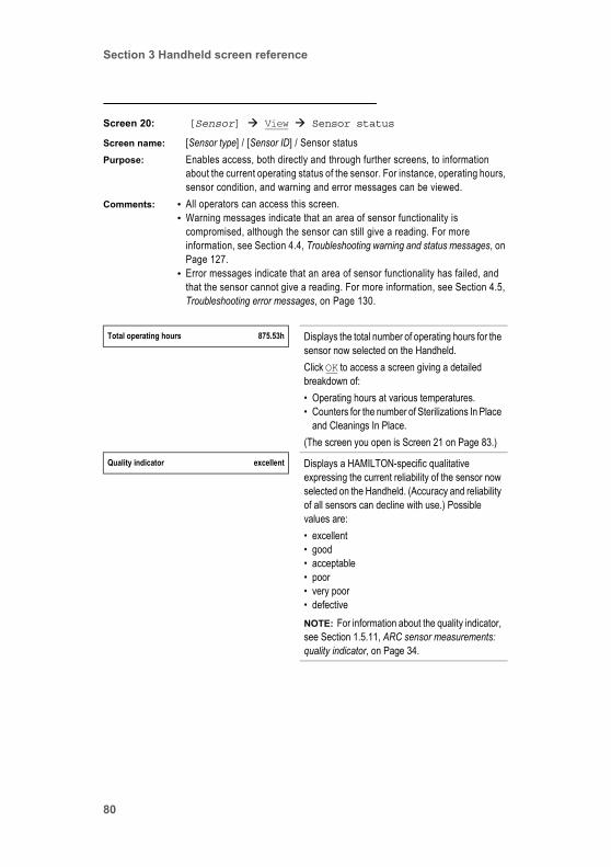
Section 3 Handheld screen reference
Screen 20: [Sensor] View Sensor status
Screen name: [Sensor type] / [Sensor ID] / Sensor statusPurpose: Enables access, both directly and through further screens, to information
about the current operating status of the sensor. For instance, operating hours, sensor condition, and warning and error messages can be viewed.
Comments: • All operators can access this screen.• Warning messages indicate that an area of sensor functionality is
compromised, although the sensor can still give a reading. For more information, see Section 4.4, Troubleshooting warning and status messages, on Page 127.
• Error messages indicate that an area of sensor functionality has failed, and that the sensor cannot give a reading. For more information, see Section 4.5, Troubleshooting error messages, on Page 130.
Total operating hours 875.53h Displays the total number of operating hours for the sensor now selected on the Handheld.Click OK to access a screen giving a detailed breakdown of:• Operating hours at various temperatures.• Counters for the number of Sterilizations In Place
and Cleanings In Place.(The screen you open is Screen 21 on Page 83.)
Quality indicator excellent Displays a HAMILTON-specific qualitative expressing the current reliability of the sensor now selected on the Handheld. (Accuracy and reliability of all sensors can decline with use.) Possible values are:• excellent• good• acceptable• poor• very poor• defectiveNOTE: For information about the quality indicator, see Section 1.5.11, ARC sensor measurements: quality indicator, on Page 34.
80

Section 3 Handheld screen reference
Warnings: measurement 0 Displays the number of warning messages currently in force with respect to measurements.Click OK to access the Warnings: measurement screen for the text of each message. (This screen is very simple and intuitive, and is not documented separately below.)NOTE: For information about the messages that can be displayed, see Section 4.4.1, Measurement warnings, on Page 127.
Warnings: calibration 1 Displays the number of warning messages currently in force with respect to calibration.Click OK to access the Warnings: calibration screen for the text of each message. (This screen is very simple and intuitive, and is not documented separately below.)NOTE: For information about the messages that can be displayed, see Section 4.4.2, Calibration warnings, on Page 128.
Warnings: interface 0 Displays the number of warning messages currently in force with respect to the interface.Click OK to access the Warnings: interface screen for the text of each message. (This screen is very simple and intuitive, and is not documented separately below.)NOTE: For information about the messages that can be displayed, see Section 4.4.4, Interface warnings, on Page 129.
Warnings: hardware 0 Displays the number of warning messages currently in force with respect to hardware.Click OK to access the Warnings: hardware screen for the text of each message. (This screen is very simple and intuitive, and is not documented separately below.)NOTE: For information about the messages that can be displayed, see Section 4.4.5, Hardware warnings, on Page 130.
ARC View Handheld Operator’s Guide 81

Section 3 Handheld screen reference
Errors: measurement 0 Displays the number of error messages currently in force with respect to measurement.Click OK to access the Errors: measurement screen for the text of each message. (This screen is very simple and intuitive, and is not documented separately below.)NOTE: For information about the messages that can be displayed, see Section 4.5.1, Measurement errors, on Page 130.
Errors: calibration 0 Displays the number of error messages currently in force with respect to calibration.Click OK to access the Errors: calibration screen for the text of each message. (This screen is very simple and intuitive, and is not documented separately below.)NOTE: For information about the messages that can be displayed, see Section 4.5.2, Calibration errors, on Page 131.
Errors: interface 0 This option reserved for possible future use.
Errors: hardware 0 Displays the number of error messages currently in force with respect to hardware.Click OK to access the Errors: hardware screen for the text of each message. (This screen is very simple and intuitive, and is not documented separately below.)NOTE: For information about the messages that can be displayed, see Section 4.5.3, Hardware errors, on Page 132.
82
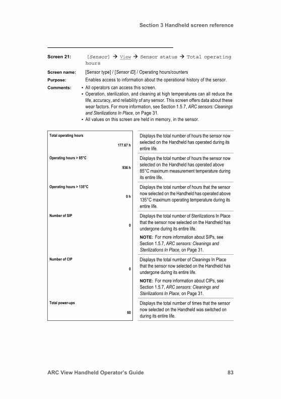
Section 3 Handheld screen reference
Screen 21: [Sensor] View Sensor status Total operating hours
Screen name: [Sensor type] / [Sensor ID] / Operating hours/countersPurpose: Enables access to information about the operational history of the sensor. Comments: • All operators can access this screen.
• Operation, sterilization, and cleaning at high temperatures can all reduce the life, accuracy, and reliability of any sensor. This screen offers data about these wear factors. For more information, see Section 1.5.7, ARC sensors: Cleanings and Sterilizations In Place, on Page 31.
• All values on this screen are held in memory, in the sensor.
Total operating hours Displays the total number of hours the sensor now selected on the Handheld has operated during its entire life.
177.67 h
Operating hours > 85°C Displays the total number of hours the sensor now selected on the Handheld has operated above 85°C maximum measurement temperature during its entire life.
936 h
Operating hours > 135°C Displays the total number of hours that the sensor now selected on the Handheld has operated above 135°C maximum operating temperature during its entire life.
0 h
Number of SIP Displays the total number of Sterilizations In Place that the sensor now selected on the Handheld has undergone during its entire life. NOTE: For more information about SIPs, see Section 1.5.7, ARC sensors: Cleanings and Sterilizations In Place, on Page 31.
0
Number of CIP Displays the total number of Cleanings In Place that the sensor now selected on the Handheld has undergone during its entire life. NOTE: For more information about CIPs, see Section 1.5.7, ARC sensors: Cleanings and Sterilizations In Place, on Page 31.
0
Total power-ups Displays the total number of times that the sensor now selected on the Handheld was switched on during its entire life.
60
ARC View Handheld Operator’s Guide 83

Section 3 Handheld screen reference
Screen 22: [Sensor] View Sensor info
Screen name: [Sensor type] / [Sensor ID] / Sensor infoPurpose: Enables access to manufacturing information uniquely identifying a sensor.Comments: • All operators can access this screen.
• See Task 4, Managing sensor STAtus profiles, on Page 51 for information about creating a file of extremely detailed sensor information.
Sensor ID 242450-3001 Displays a string identifying the sensor now selected on the Handheld. By default, the string is the sensor's part number followed by its serial number.(Specialists can change the Sensor ID. See Screen 48 on Page 122.)
Firmware version ODOUM039 Displays the version of the firmware currently loaded on a memory chip in the sensor, for the sensor now selected on the Handheld.For information about updating firmware, see Appendix B.5, ARC sensor firmware update, on Page 143.
Serial number 3001 Displays the serial number of the sensor now selected on the Handheld. (By default, the serial number is also part of the Sensor ID.)This value is set in the factory and cannot be changed.
Workorder number 296588/399 Displays the workorder number of the sensor now selected on the Handheld. This number can be useful in tracing faulty sensors to production runs.This value is set in the factory and cannot be changed.
Part number 242450 Displays the part number of the sensor now selected on the Handheld.This value is set in the factory and cannot be changed.
Productname VISIFERM DO 120 Displays the product name of the sensor now selected on the Handheld.This string is set in the factory and cannot be changed.
84
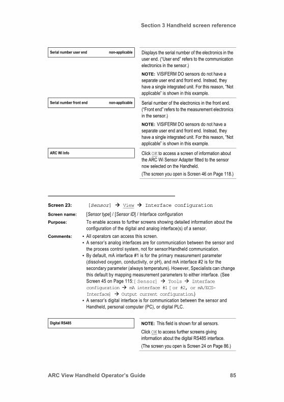
Section 3 Handheld screen reference
Screen 23: [Sensor] View Interface configuration
Screen name: [Sensor type] / [Sensor ID] / Interface configurationPurpose: To enable access to further screens showing detailed information about the
configuration of the digital and analog interface(s) of a sensor.Comments: • All operators can access this screen.
• A sensor’s analog interfaces are for communication between the sensor and the process control system, not for sensor/Handheld communication.
• By default, mA interface #1 is for the primary measurement parameter (dissolved oxygen, conductivity, or pH), and mA interface #2 is for the secondary parameter (always temperature). However, Specialists can change this default by mapping measurement parameters to either interface. (See Screen 45 on Page 115: [Sensor] Tools Interface configuration mA interface #1 [or #2, or mA/ECS-Interface] Output current configuration.)
• A sensor’s digital interface is for communication between the sensor and Handheld, personal computer (PC), or digital PLC.
Serial number user end non-applicable Displays the serial number of the electronics in the user end. (“User end” refers to the communication electronics in the sensor.)NOTE: VISIFERM DO sensors do not have a separate user end and front end. Instead, they have a single integrated unit. For this reason, “Not applicable” is shown in this example.
Serial number front end non-applicable Serial number of the electronics in the front end. (“Front end” refers to the measurement electronics in the sensor.)NOTE: VISIFERM DO sensors do not have a separate user end and front end. Instead, they have a single integrated unit. For this reason, “Not applicable” is shown in this example.
ARC Wi Info Click OK to access a screen of information about the ARC Wi Sensor Adapter fitted to the sensor now selected on the Handheld.(The screen you open is Screen 46 on Page 118.)
Digital RS485 NOTE: This field is shown for all sensors.Click OK to access further screens giving information about the digital RS485 interface.(The screen you open is Screen 24 on Page 86.)
ARC View Handheld Operator’s Guide 85
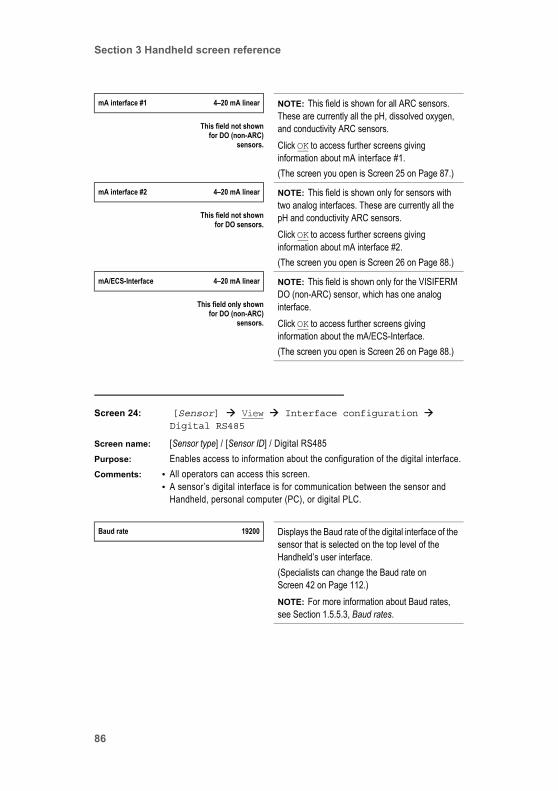
Section 3 Handheld screen reference
Screen 24: [Sensor] View Interface configuration Digital RS485
Screen name: [Sensor type] / [Sensor ID] / Digital RS485Purpose: Enables access to information about the configuration of the digital interface. Comments: • All operators can access this screen.
• A sensor’s digital interface is for communication between the sensor and Handheld, personal computer (PC), or digital PLC.
mA interface #1 4–20 mA linear NOTE: This field is shown for all ARC sensors. These are currently all the pH, dissolved oxygen, and conductivity ARC sensors.Click OK to access further screens giving information about mA interface #1.(The screen you open is Screen 25 on Page 87.)
This field not shownfor DO (non-ARC)
sensors.
mA interface #2 4–20 mA linear NOTE: This field is shown only for sensors with two analog interfaces. These are currently all the pH and conductivity ARC sensors.Click OK to access further screens giving information about mA interface #2.(The screen you open is Screen 26 on Page 88.)
This field not shownfor DO sensors.
mA/ECS-Interface 4–20 mA linear NOTE: This field is shown only for the VISIFERM DO (non-ARC) sensor, which has one analog interface.Click OK to access further screens giving information about the mA/ECS-Interface.(The screen you open is Screen 26 on Page 88.)
This field only shownfor DO (non-ARC)
sensors.
Baud rate 19200 Displays the Baud rate of the digital interface of the sensor that is selected on the top level of the Handheld’s user interface.(Specialists can change the Baud rate on Screen 42 on Page 112.)NOTE: For more information about Baud rates, see Section 1.5.5.3, Baud rates.
86
Section 3 Handheld screen reference
Screen 25: [Sensor] View Interface configuration mA interface #1 [or #2]
Screen name: [Sensor type] / [Sensor ID] / Analog 1Purpose: Enables access to information about the configuration of mA interface #1.Comments: • All operators can access this screen.
• A sensor’s analog interfaces are for communication between the sensor and the process control system, not for sensor/Handheld communication.
• By default, mA interface #1 is for the primary measurement parameter (dissolved oxygen, conductivity, or pH), and mA interface #2 is for the secondary parameter (always temperature). However, Specialists can change this default by mapping measurement parameters to either interface. (See Screen 45 on Page 115: [Sensor] Tools Interface configuration mA interface #1 [or #2, or mA/ECS-Interface] Output current configuration.)
Modbus device address 1 Displays the Modbus device address of the sensor now selected on the Handheld.(Specialists can change the Modbus device address on Screen 42 on Page 112.)NOTE: For more information about Modbus device addresses, see Section 1.5.5.2, Modbus device addresses.
Parity none Displays the parity status of the RS485 interface. (This value is required for programming the PLC.) Operators cannot change this status.
Stop bits 2 Displays the number of stop bits set for the RS485 interface. (This value is required for programming the PLC.) Operators cannot change this status.
Interface mode 4–20 mA linear Displays, for the sensor now selected on the Handheld, the interface mode currently set for mA interface #1.For more information about interface modes, see Section 1.5.6.3, Configuring the mode of the analog interfaces.
ARC View Handheld Operator’s Guide 87

Section 3 Handheld screen reference
Screen 26: [Sensor] View Interface configuration mA/ECS-Interface
Screen name: [Sensor type] / [Sensor ID] / Analog 1Purpose: Enables access to information about the configuration of the mA/ECS interface
found only on the VISIFERM DO (non-ARC) sensor. (The ECS interface is designed to emulate an electro-chemical sensor’s output.)
Comments: • All operators can access this screen.• The VISIFERM DO ARC sensor’s analog interface is for communication
between the sensor and the process control system, not for sensor/Handheld communication.
Output current configuration Click OK to access a screen showing the mapping of:• Analog interface output values
to• Measurement parameter valuesfor mA interface #1 of the sensor now selected on the Handheld.(The screen you open is Screen 27 on Page 90).
Error/warning configuration Click OK to access a screen showing the mapping of:• Analog interface output values
to • Errors and warnings for mA interface #1 of the sensor now selected on the Handheld.(The screen you open is Screen 28 on Page 92.)
Interface mode 4–20 mA linear Displays, for the VISIFERM DO (non-ARC) sensor now selected on the Handheld, the interface mode currently set.NOTE: For more information about interface modes, see Section 1.5.6.3, Configuring the mode of the analog interfaces.
88

Section 3 Handheld screen reference
Output current configuration Click OK to access a screen showing the mapping of:• Analog interface output values
to• Measurement parameter valuesfor the analog interface of the VISIFERM DO (non-ARC) sensor now selected on the Handheld.(The screen you open is Screen 27 on Page 90).
Error/warning configuration Click OK to access a screen showing the mapping of:• Analog interface output values
to• Errors and warnings for the analog interface of the VISIFERM DO (non-ARC) sensor now selected on the Handheld.(The screen you open is Screen 28 on Page 92.)
ARC View Handheld Operator’s Guide 89

Section 3 Handheld screen reference
Screen 27: [Sensor] View Interface configuration mA interface #1 [or #2, or mA/ECS-Interface] Output current configuration
Screen name: [Sensor type] / [Sensor ID] / Configuration output currentPurpose: Enables access to information about the configuration of mA interface #1 or
#2, for pH and conductivity ARC sensors, and the single analog ECS interface of VISIFERM DO (non-ARC) sensors, depending on selections made in previous screens.
Comments: • All operators can access this screen.• A sensor’s analog interfaces are for communication between the sensor and
the process control system, not for sensor/Handheld communication.• By default, mA interface #1 is for the primary measurement parameter
(dissolved oxygen, conductivity, or pH), and mA interface #2 is for the secondary parameter (always temperature). However, Specialists can change this default by mapping measurement parameters to either interface. (See Screen 45 on Page 115: [Sensor] Tools Interface configuration mA interface #1 [or #2, or mA/ECS-Interface] Output current configuration.)
Interface mode 4–20 mA linear Displays the mode currently set for the selected analog interface of the sensor selected on the Handheld. This analog interface can be:• mA interface #1• mA interface #2• mA ECS-Interface (the single ECS analog
interface of a VISIFERM DO (non-ARC) sensor)NOTE: For more information about interface modes, see Section 1.5.6.3, Configuring the mode of the analog interfaces.
Measurement variable T Displays the measurement variable currently assigned to the selected analog interface of the sensor selected on the Handheld.NOTE: By default, the primary measurement variable of the sensor, DO (dissolved oxygen), pH, or Cond (conductivity) is assigned to mA interface #1. However, Specialists can change this to the secondary measurement parameter, T (temperature) on Screen 45 on Page 115.
90
Section 3 Handheld screen reference
Value at 4 mA 0°C Displays, for the selected analog interface of the sensor now selected on the Handheld, the mapping between:• The lowest output current (4 mA) of the analog
interface.• A measurement parameter value of the sensor.As an example shown, a temperature of 0°C causes the sensor to output a current of 4 mA.(Specialists can set this mapping on Screen 45 on Page 115.)NOTE: For more information, see Section 1.5.6.3, Configuring the mode of the analog interfaces.
Value at 20 mA 35.00°C Displays, for the selected analog interface of the sensor now selected on the Handheld, the mapping between:• The highest output current (20 mA) of the analog
interface.• A measurement parameter value of the sensor.In the example shown here, a temperature of 35.00°C causes the sensor to output a current of 20 mA.(Specialists can set this mapping on Screen 45 on Page 115.)NOTE: For more information, see Section 1.5.6.3, Configuring the mode of the analog interfaces.
Active output signal 14.1 mA Displays, for the selected analog interface of the sensor now selected on the Handheld, the current that is being output at this time.This current is for the measurement parameter set in the Measurement variable field shown above.NOTE: The value shown is valid and accurate only when the output is correctly connected to an analog PLC.
ARC View Handheld Operator’s Guide 91

Section 3 Handheld screen reference
Screen 28: [Sensor] View Interface configuration mA interface #1 [or #2, or mA/ECS-Interface] Error/warning configuration
Screen name: [Sensor type] / [Sensor ID] / Configuration error / warningPurpose: Enables the viewing of the analog interface’s defined responses to errors and
warnings.Comments: • All operators can access this screen.
• A sensor’s analog interface or interfaces are for communication between the sensor and the process control system, not for sensor/Handheld communication.
Interface mode 4–20 mA linear Displays, for the sensor now selected on the Handheld, the interface mode of the selected analog interface.(Specialists can set the interface mode on Screen 43 on Page 113.)NOTE: For more information about interface modes, see Section 1.5.6.3, Configuring the mode of the analog interfaces.
Mode in event of warning No output Displays, for the sensor now selected on the Handheld, the response of the selected analog interface when a warning is active.The analog interface can be configured to respond in one of three ways in event of a warning:• Continuous: The analog interface sends a
continuous signal to the process control system.• Alternating: The analog interface sends a
square wave signal to the process control system.
• No output: The analog interface sends no signal to the process control system.
NOTE: For more information, see Output in event of warning below.
Mode in event of error Continuous Displays, for the sensor now selected on the Handheld, the response of the selected analog interface when an error status is triggered by the sensor.NOTE: For more information, see Output in event of warning below.
92

Section 3 Handheld screen reference
Screen 29: [Sensor] Tools
Screen name: [Sensor type] / [Sensor ID] / ToolsPurpose: Enables Administrators and specialists to access a range of screens showing
very detailed information concerning the identity and current status of the selected sensor. Administrators and Specialists can calibrate sensors. Specialists can configure sensors.
Output in event of warning 3.5 mA Displays, for the sensor now selected on the Handheld, the output current from the selected analog interface when a warning is active.An appropriate warning message is generated. For more information, see Section 4.4, Troubleshooting warning and status messages, on Page 127.
Output in event of error 3.5 mA Displays, for the sensor now selected on the Handheld, the output current from the selected analog interface when an error is active.An appropriate error message is generated. For more information, see Section 4.4, Troubleshooting warning and status messages, on Page 127.
Output for T out of limit 3.5 mA Displays, for the sensor now selected on the Handheld, the output current configured for the selected analog interface to indicate that temperature is above its accepted range.In this way, you can use the temperature measurement as an alarm device.NOTE: All ARC sensors have a temperature measurement function.
Measurement Click OK to access a range of screens giving very detailed information about the sensor now selected on the Handheld. (The first screen you open is Screen 30 on Page 95.)
ARC View Handheld Operator’s Guide 93

Section 3 Handheld screen reference
Calibration Click OK to access screens giving full details of the last calibration of the sensor now selected on the Handheld. These screens also enable Specialists to perform calibrations on the sensor. (The first screen you open is Screen 34 on Page 100.)
Sensor status Click OK to access details of the operating status of the sensor now selected on the Handheld, with respect to:• Total operating hours of the sensor.• Quality indicator of the reading.• Active warning or error messages.(The screen you open is Screen 40 on Page 110.)
Interface configuration Click OK to access further screens offering full details of the following, for the sensor now selected on the Handheld:• The digital RS485 configuration• The analog 4–20 mA configuration(s)These screens also enable Specialists to make changes to the configuration of these interfaces.(The first screen you open is Screen 41 on Page 110.)
Data management Click OK to access further screens enabling Specialists to do the following for the sensor now selected on the Handheld:• Copy a sensor STAtus profile (STA) from the
sensor to the Handheld.(See Task 4, Managing sensor STAtus profiles, on Page 51.)
• Update the firmware in the sensor.(See Appendix B.5, ARC sensor firmware update.)
(The first screen you open is Screen 47 on Page 120.)
Sensor info Click OK to access a screen showing identification details of the sensor now selected on the Handheld, and enabling Specialists to change the Sensor ID.(The screen you open is Screen 42 on Page 112.)
94

Section 3 Handheld screen reference
Screen 30: [Sensor] Tools Measurement
Screen name: [Sensor type] / [Sensor ID] / MeasurementPurpose: Displays current measurements, units for measurements, parameters for
measurements, and definitions of CIPs and SIPs valid within the ARC system. Specialists can set the units used in some fields.
Comments: This screen is password protected. Only specialists can make changes.
Measurement data Click OK to access the real-time values of the measurements being made now, by the sensor selected on the Handheld.(Accessing this information is a two-step process, starting at Screen 31 on Page 98.)
Graph/data log Click OK to access a real-time graph of measurements being made by the sensor selected on the Handheld. While this screen is opened, data will be logged in a trace file.(Accessing this information is a two-step process, starting at Screen 19 on Page 79.)
Unit for DO %-vol Displays the measurement unit currently set for the measurement parameter indicated, for the sensor now selected on the Handheld.In the example shown here, the parameter dissolved oxygen is measured in the unit percentage by volume.Click OK to access a screen enabling you to set different measurement units for this parameter. The units available depend on the parameter.
Unit for T °C Displays the measurement unit currently set for the measurement parameter indicated, for the sensor now selected on the Handheld.In the example shown on the left, the parameter temperature is measured in the unit degrees Centigrade.Click OK to access a screen enabling you to set different measurement units for this parameter.
ARC View Handheld Operator’s Guide 95

Section 3 Handheld screen reference
Salinity 1mS/cm Displays the salinity level currently set for the sensor now selected on the Handheld. This parameter enables you to calculate the correct oxygen concentrations in different aqueous solutions.Click OK to access a screen enabling you to set a different value for solution salinity. (This screen is very simple and intuitive, and is not documented separately below.)NOTE: The unit delivered by the sensor is always the conductivity unit, micro Siemens per centimeter, and cannot be changed.
This field applies to thedissolved oxygen
sensor only
Air pressure 913mbar Displays the air pressure currently set for the environment of the sensor now selected on the Handheld.Click OK to access a screen enabling you to set a different value for this pressure. This screen is very simple and intuitive, and is not documented separately below.) NOTE: The unit delivered by the sensor is always the millibar, and cannot be changed.
This field applies to thedissolved oxygen
sensor only
Temp. comp. factor 0%/K Displays the compensation factor currently set for the reading made by the conductivity sensor now selected on the Handheld.Click OK to access a screen enabling you to set a different value for this compensation factor. (This screen is very simple and intuitive, and is not documented separately below.) NOTE: For more information, see Section 1.5.10, ARC sensor measurements: temperature compensation factor, on Page 34.
This field applies to theconductivity sensor
only
96

Section 3 Handheld screen reference
Moving average 16 Displays the moving average currently set for measurements made by the sensor selected on the Handheld.NOTE: With pH sensors, the figure is an average over the measurement of a resistance, and the label Moving average R is used.• The DO sensor accepts a value from 1 to 30.
Alternatively, a value of 0 initiates automatic setting of the value by the sensor.
• The pH sensor accepts a value of 1 to 16. • The conductivity sensor accepts a value of
1 to 16. Click OK to access a screen enabling you to set a different value for moving average. (This screen is very simple and intuitive, and is not documented separately below.)NOTE: For more information, see Section 1.5.8, ARC sensor measurements: moving average, on Page 32.
Resolution 3 Displays the resolution currently set for measurements made by the sensor selected on the Handheld. In the example shown on the left, the value of 3 has been set.Click OK to access a screen enabling you to set a different value for resolution. The DO sensor uses this parameter, and accepts a value of 1 to 16. Alternatively, you can enter a value of 0 to initiate automatic setting of the value by the DO sensor. (This screen is very simple and intuitive, and is not documented separately below.)NOTE: For more information, see Section 1.5.9, ARC sensor measurements: resolution, on Page 32.
This field applies to thedissolved oxygen
sensor only
CIP/SIP definition Click OK to access a screen displaying information about the parameters set for Cleaning In Place and Sterilization In Place. Further screens enable you to make changes to these parameters.(The screen you open is Screen 32 on Page 98.)
ARC View Handheld Operator’s Guide 97
Section 3 Handheld screen reference
Screen 31: [Sensor] Tools Measurement Measurement data
Screen name: [Sensor type] / [Sensor ID] / Measurement dataPurpose: Displays primary and secondary parameter measurements of the associated
sensor (pH, dissolved oxygen, conductivity, temperature). In addition, also shows the underlying measurement parameters from which the primary parameters are calculated. The fields shown on this screen depend on the type of sensor to which they refer and to the level of the operator accessing them.
Comments: For more information, see the sensor manuals and programmer’s manuals listed in Appendix A.5, on Page 137.
Screen 32: [Sensor] Tools Measurement CIP/SIP definition
Screen name: [Sensor type] / [Sensor ID] / CIP/SIP definitionPurpose: Displays the current definition of parameters defining the Cleanings In Place
(CIPs) and Sterilizations In Place (SIPs) events. Specialists can make changes to parameter values.
Comments: For more information about CIPs and SIPs, see Section 1.5.7, ARC sensors: Cleanings and Sterilizations In Place, on Page 31.
SIP min. temperature 120°C Displays the minimum temperature at which a Sterilization In Place event is recognized by the sensor selected on the Handheld. SIPs below this temperature, as measured by the sensor, are not counted.Click OK to access a screen enabling you to set a different value for this parameter.
SIP max. temperature 135°C Displays the maximum temperature at which a Sterilization In Place event is recognized by the sensor selected on the Handheld. SIPs above this temperature, as measured by the sensor, are not counted.Click OK to access a screen enabling you to set a different value for this parameter.
98

Section 3 Handheld screen reference
Screen 33: [Sensor] Tools Measurement Graph/data log
Screen name: [Sensor type] / [Sensor ID] / Graph/data logPurpose: Displays a graph for real-time measurements. This is similar to Screen 19 on
Page 79: [Sensor] View Graph..Additionally, a trace file will be generated. For more information about trace files, see Task 5, Managing trace files, on Page 53.
SIP min. time span 30 min Displays the minimum time period over which a Sterilization In Place event is recognized by the sensor selected on the Handheld. SIPs that take place over a shorter period, as measured by the sensor, are not counted.Click OK to access a screen enabling you to set a different value for this parameter.
CIP min. temperature 80°C Displays the minimum temperature at which a Cleaning In Place is recognized by the sensor selected on the Handheld. CIPs below this temperature, as measured by the sensor, are not counted. Click OK to access a screen enabling you to set a different value for this parameter.
CIP max. temperature 100°C Displays the maximum temperature at which a Cleaning In Place event is recognized by the sensor selected on the Handheld. CIPs above this temperature, as measured by the sensor, are not counted.Click OK to access a screen enabling you to set a different value for this parameter.
CIP min. time span 30 min Displays the minimum time period over which a Cleaning In Place event is recognized by the sensor selected on the Handheld. CIPs that take place over a shorter period, as measured by the sensor, are not counted.Click OK to access a screen enabling you to set a different value for this parameter.
ARC View Handheld Operator’s Guide 99
Section 3 Handheld screen reference
Screen 34: [Sensor] Tools Calibration
Screen name: [Sensor type] / [Sensor ID] / CalibrationPurpose: Enables Administrators and Specialists to perform sensor calibrations and
view the corresponding data.Comments: None.
Calibration data Click OK to access a screen displaying the calibration values set for calibration of the primary parameter of the sensor now selected on the Handheld.Further screens give full details of all parameter values at the time of the last calibration.(The screen you open is Screen 35 on Page 101.)
Calibrate Click OK to access a screen enabling you to calibrate the primary parameter of the sensor now selected on the Handheld.(The screen you open is Screen 38 on Page 106.)
100
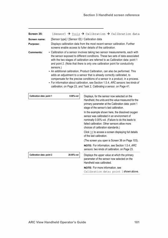
Section 3 Handheld screen reference
Screen 35: [Sensor] Tools Calibration Calibration data
Screen name: [Sensor type] / [Sensor ID] / Calibration dataPurpose: Displays calibration data from the most recent sensor calibration. Further
screens enable access to fuller details of the calibration.Comments: • Calibration of a sensor involves taking two sensor measurements, each with
the sensor exposed to different conditions. These two sets of data associated with the two stages of calibration are referred to as Calibration data: point 1 and point 2. (Note that there is only one calibration point for conductivity sensors.)
• An additional calibration, Product Calibration, can also be performed. This adds an adjustment to a sensor that is already correctly calibrated, to compensate for the precise conditions of a sensor in a product, in a process.
• For information about calibration, see Section 1.5.4, ARC sensors: two kinds of calibration, on Page 23, and Task 2, Calibrating a sensor, on Page 41.
Calibration data: point 1 0.00%-vol Displays, for the sensor now selected on the Handheld, the units and the value measured for the primary parameter at the Calibration data: point 1 stage of the sensor’s last calibration.In the example shown here, the dissolved oxygen sensor was calibrated in an environment of nominally 0.00%-vol. (Failure to do this leads to failed calibration. Other sensors allow more choices of calibration standards.)Click OK to access a screen displaying full details of the last calibration.(The screen you open is Screen 36 on Page 103).NOTE: For information, see Section 1.5.4, ARC sensors: two kinds of calibration, on Page 23.
Calibration data: point 2 20.95%-vol Displays the upper value at which the primary parameter of the sensor now selected on the Handheld was calibrated.NOTE: For more information, see Calibration data: point 1 shown above.
ARC View Handheld Operator’s Guide 101
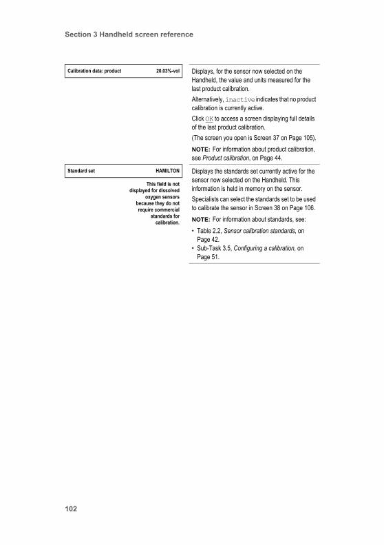
Section 3 Handheld screen reference
Calibration data: product 20.03%-vol Displays, for the sensor now selected on the Handheld, the value and units measured for the last product calibration.Alternatively, inactive indicates that no product calibration is currently active.Click OK to access a screen displaying full details of the last product calibration.(The screen you open is Screen 37 on Page 105).NOTE: For information about product calibration, see Product calibration, on Page 44.
Standard set HAMILTON Displays the standards set currently active for the sensor now selected on the Handheld. This information is held in memory on the sensor.Specialists can select the standards set to be used to calibrate the sensor in Screen 38 on Page 106.NOTE: For information about standards, see:• Table 2.2, Sensor calibration standards, on
Page 42.• Sub-Task 3.5, Configuring a calibration, on
Page 51.
This field is notdisplayed for dissolved
oxygen sensorsbecause they do notrequire commercial
standards forcalibration.
102
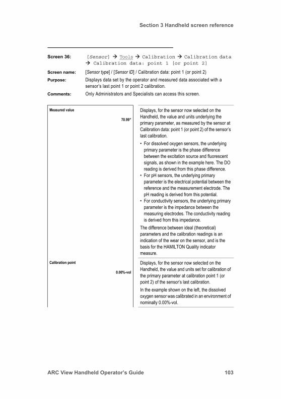
Section 3 Handheld screen reference
Screen 36: [Sensor] Tools Calibration Calibration data Calibration data: point 1 [or point 2]
Screen name: [Sensor type] / [Sensor ID] / Calibration data: point 1 (or point 2)Purpose: Displays data set by the operator and measured data associated with a
sensor’s last point 1 or point 2 calibration.Comments: Only Administrators and Specialists can access this screen.
Measured value Displays, for the sensor now selected on the Handheld, the value and units underlying the primary parameter, as measured by the sensor at Calibration data: point 1 (or point 2) of the sensor’s last calibration.• For dissolved oxygen sensors, the underlying
primary parameter is the phase difference between the excitation source and fluorescent signals, as shown in the example here. The DO reading is derived from this phase difference.
• For pH sensors, the underlying primary parameter is the electrical potential between the reference and the measurement electrode. The pH reading is derived from this potential.
• For conductivity sensors, the underlying primary parameter is the impedance between the measuring electrodes. The conductivity reading is derived from this impedance.
The difference between ideal (theoretical) parameters and the calibration readings is an indication of the wear on the sensor, and is the basis for the HAMILTON Quality indicator measure.
70.99°
Calibration point Displays, for the sensor now selected on the Handheld, the value and units set for calibration of the primary parameter at calibration point 1 (or point 2) of the sensor’s last calibration.In the example shown on the left, the dissolved oxygen sensor was calibrated in an environment of nominally 0.00%-vol.
0.00%-vol
ARC View Handheld Operator’s Guide 103

Section 3 Handheld screen reference
Temperature Displays, for the sensor now selected on the Handheld, the temperature recorded by the sensor at calibration point 1 (or point 2) of the sensor’s last calibration.In the example shown on the left, the dissolved oxygen sensor was calibrated at a temperature of 26.85°C.NOTE: This value is measured and recorded by the sensor during calibration. This value is not set prior to calibration.
26.85°C
Airpressure NOTE: This field applies to the dissolved oxygen sensor only.Displays, for the DO sensor now selected on the Handheld, the air pressure set for the process environment at calibration point 1 (or point 2) of the sensor’s last calibration. (A Specialist sets this on Screen 30 on Page 95.)NOTE: This value is set prior to calibration. This value is not measured or recorded by the sensor during calibration. (However, during calibration, the value for pressure is used as a correction factor to calculate the oxygen partial pressure).
1013.00 mbarThis field is shown
only for the dissolvedoxygen sensor
Salinity NOTE: This field applies to the dissolved oxygen sensor only.Displays, for the DO sensor now selected on the Handheld, the salinity set for measurements in solutions (A Specialist sets this on Screen 30 on Page 95.)NOTE: This value is set prior to calibration. This value is not measured or recorded by the sensor during calibration.
0.00 mS/cmThis field is shown
only for the dissolvedoxygen sensor
Operating hours Displays, for the sensor now selected on the Handheld, the total number of sensor operating hours recorded by the sensor during its life. This value acts as a time stamp to mark the time at which the calibration takes place.NOTE: This value is recorded by the sensor.
0.42 h
104

Section 3 Handheld screen reference
Screen 37: [Sensor] Tools Calibration Calibration data Calibration data: product
Screen name: [Sensor type] / [Sensor ID] / Calibration data: productPurpose: Displays both data set by the operator and measured data associated with the
sensor’s last product calibration. Data is recorded by the sensor.Comments: This screen is identical to Screen 36 on Page 103, except that it is for
Calibration data: product, not for Calibration data: point 1 or point 2.
Zero point (+25°C) Displays, for the sensor now selected on the Handheld, the value and units of the sensor’s first characteristic parameter:• DO sensor: Phase signal value at zero oxygen.• Conductivity sensor: Impedance offset.• pH sensor: Isopotential point at pH=7.0.This figure acts as a performance reference value for the sensor. NOTE: This value is calculated from a measurement during calibration, and recorded by the sensor.
Sensitivity (25°C) Displays, for the sensor now selected on the Handheld, the value and units of the sensor’s second characteristic parameter:• DO sensor: Stern-Volmer coefficient.• Conductivity sensor: Cell constant. • pH sensor: Slope of pH calibration curve.This figure acts as a performance reference value for the sensor.NOTE: This value is calculated from a measurement during calibration, and recorded by the sensor.
ARC View Handheld Operator’s Guide 105

Section 3 Handheld screen reference
Screen 38: [Sensor] Tools Calibration Calibrate
Screen name: [Sensor type] / [Sensor ID] / CalibratePurpose: Enables automatic standard calibration of sensors.Comments: • Only Administrators and Specialists can access it.
• Neither this screen or any other enables the setting of calibration values.• For information about calibration, see Section 1.5.4, ARC sensors: two kinds of
calibration, on Page 23, and Task 2, Calibrating a sensor, on Page 41.
Calibrate at point 1 0.00%-vol Displays, for the sensor now selected on the Handheld, the value and units set for the last calibration. This is dependent on the standards set selected. (See the Select standard set field on Screen 38, Page 107, and Sub-Task 3.5, Configuring a calibration, on Page 51.)NOTE: For successful calibration, one calibration standard from a predefined set suitable for the sensor must be used. The sensor automatically recognizes the standard and allows the calibration. In the example shown here, the dissolved oxygen sensor must be in an environment of 0.00% oxygen.Click OK to calibrate the sensor at Calibration point 1. The sensor performs the calibration immediately and the Handheld displays a screen informing you whether the calibration was successful or not.
NOTE: If calibration fails at one of the calibration points, the sensor can still be used. However, the measured value can be compromised. Measurement reliability is expressed as the Quality indicator field in Screen 20 on Page 80.NOTE: The calibration procedure will last up to 180 seconds. If the standard is not recognized or the values are not stable, calibration will be cancelled automatically with a corresponding warning message.NOTE: If calibration fails, a warning message is displayed. For more information, see Section 4.4.3, Calibration status messages, on Page 128.
106
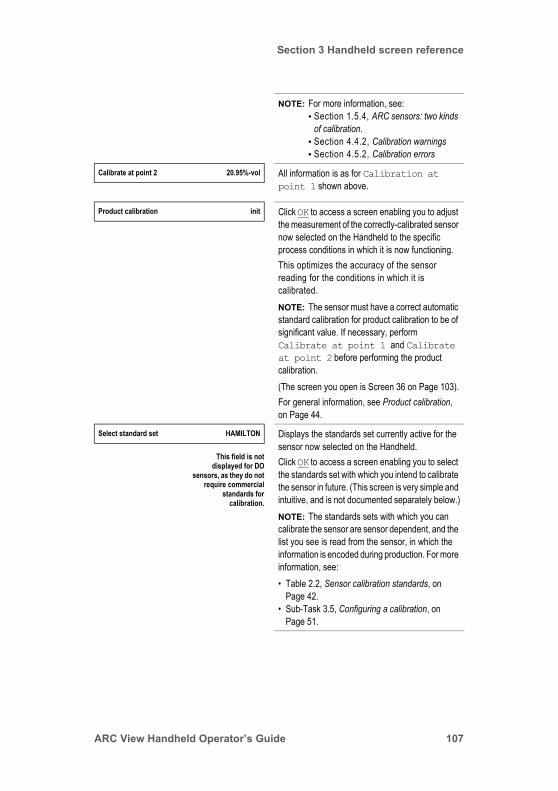
Section 3 Handheld screen reference
NOTE: For more information, see:• Section 1.5.4, ARC sensors: two kinds
of calibration.• Section 4.4.2, Calibration warnings• Section 4.5.2, Calibration errors
Calibrate at point 2 20.95%-vol All information is as for Calibration at point 1 shown above.
Product calibration init Click OK to access a screen enabling you to adjust the measurement of the correctly-calibrated sensor now selected on the Handheld to the specific process conditions in which it is now functioning.This optimizes the accuracy of the sensor reading for the conditions in which it is calibrated.NOTE: The sensor must have a correct automatic standard calibration for product calibration to be of significant value. If necessary, perform Calibrate at point 1 and Calibrate at point 2 before performing the product calibration.(The screen you open is Screen 36 on Page 103).For general information, see Product calibration, on Page 44.
Select standard set HAMILTON Displays the standards set currently active for the sensor now selected on the Handheld.Click OK to access a screen enabling you to select the standards set with which you intend to calibrate the sensor in future. (This screen is very simple and intuitive, and is not documented separately below.)NOTE: The standards sets with which you can calibrate the sensor are sensor dependent, and the list you see is read from the sensor, in which the information is encoded during production. For more information, see:• Table 2.2, Sensor calibration standards, on
Page 42.• Sub-Task 3.5, Configuring a calibration, on
Page 51.
This field is notdisplayed for DO
sensors, as they do notrequire commercial
standards forcalibration.
ARC View Handheld Operator’s Guide 107

Section 3 Handheld screen reference
Screen 39: [Sensor] Tools Calibration Calibrate Product calibration
Screen name: [Sensor type] / [Sensor ID] / Product calibrationPurpose: Enables Specialists to adjust the measurement of a correctly-calibrated ARC
Sensor to specific process conditions. This optimizes the accuracy of the primary sensor reading (pH, conductivity, or dissolved oxygen) for the conditions in the process environment at the time of calibration. Note that the temperature reading of a sensor cannot be adjusted in this manner.
Comments: This screen is password protected. Only Administrators and Specialists can access it.
Initial measurement 7.05 mV For the sensor now selected in the Handheld, displays the status of the initial measurement of the product calibration procedure. The status can be:• inactive
This shows that no initial measurement has been made, or that the initial measurement has been deleted from memory on the sensor by using Cancel below. This means that product calibration is not active, and the measurement displayed on the Handheld for the sensor’s primary parameter is affected only by the automatic standard calibration.
• [value unit]This shows that an initial measurement has been made, and is in memory in the sensor. The unit and the value depend on the sensor type and the condition of the process, respectively.Note that the units are not those of the sensor’s named primary measurement: pH, dissolved oxygen, or conductivity. Instead, they are the units of the underlying measurement, from which the primary measurement is derived:Visiferm DO (dissolved oxygen): degrees °pH: mVCond (conductivity):
Click OK to perform the initial measurement. This records the value that the sensor is currently reading. This is held in the memory of the sensor for future reference.For more information, see:• Automatic standard calibration, on Page 42.• Product calibration, on Page 44.
108

Section 3 Handheld screen reference
Assignment init Displays the status of the primary parameter assigned to the Initial measurement. The possibilities are:• inactive
This shows that product calibration is not active, although there is an Initial measurement stored in the sensor’s memory. This means that the measurement displayed on the Handheld for the sensor’s primary parameter is adjusted only by the automatic standard calibration.
• initThis shows that no value (for the sensor’s primary parameter) has been assigned to the Initial measurement. This means that product calibration is not active, and the measurement displayed on the Handheld for the sensor’s primary parameter is adjusted only by the automatic standard calibration.
• [value unit]This shows that a value for the sensor’s primary parameter (pH, dissolved oxygen, or conductivity) has been assigned to the Initial measurement. An adjustment for product calibration is being made to the measurement displayed in the Handheld for the sensor’s primary parameter.
If necessary, click OK to assign a value for pH, dissolved oxygen, or conductivity to the Initial measurement. When you do this, you activate product calibration.(The screen you open is very simple and intuitive, and is not documented separately below.)
This field is onlydisplayed if an initial
measurement hasbeen performed
Cancel Click OK to delete the Initial measurement from the memory of the sensor. This inactivates product calibration.
This field is onlydisplayed if an initial
measurement hasbeen performed
ARC View Handheld Operator’s Guide 109
Section 3 Handheld screen reference
Screen 40: [Sensor] Tools Sensor status
Screen name: [Sensor type] / [Sensor ID] / Sensor statusPurpose: Enables access, both directly and through further screens, to information
about the current operating status of the sensor. For instance, operating hours, calibration status, and warning and error messages can be viewed.
Comments: This screen is identical to Screen 20 on Page 80: [Sensor] View Sensor status. See this screen for description.
Screen 41: [Sensor] Tools Interface configuration
Screen name: [Sensor type] / [Sensor ID] / Interface configurationPurpose: Enables Specialists to change the configurations of the interfaces using further
screens.Comments: • This screen is password protected. Only Specialists can access it.
• A sensor’s analog interfaces are for communication between the sensor and the analog PLC system, not for sensor/Handheld communication.
• By default, mA interface #1 is for the primary measurement parameter (dissolved oxygen, conductivity, or pH), and mA interface #2 is for the secondary parameter (temperature). However, Specialists can change this default by mapping measurement parameters to either interface. (See Screen 45 on Page 115: [Sensor] Tools Interface configuration mA interface #1 [or #2, or mA/ECS-Interface] Output current configuration.)
• A sensor’s digital interface is for communication between the sensor and Handheld, personal computer (PC), or digital PLC.
Digital RS485 Click OK to access further screens enabling you to configure the RS485 digital interface for the sensor now selected on the Handheld.(The screen you open is Screen 42 on Page 112.)
110

Section 3 Handheld screen reference
mA interface #1 4–20mA linear Displays, for the sensor now selected on the Handheld, the interface mode currently set for mA interface #1 (or for the only analog interface, mA/ECS-Interface, of the VISIFERM DO ARC sensor).Click OK to access further screens enabling you to configure the analog interface.(The screen you open is Screen 43 on Page 113.)NOTE: For more information about interface modes, see Section 1.5.6.3, Configuring the mode of the analog interfaces.
This field is different forDO sensors
mA interface #2 4–20mA linear NOTE: This field is not applicable to the VISIFERM DO (non-ARC) sensor, because it does not have an analog interface of this kind. It is also not applicable to the VISIFERM DO ARC sensor, because it does not have a second analog interface.Displays, for the sensor now selected on the Handheld, the interface mode currently set for mA interface #2.Click OK to access further screens enabling you to configure the analog interface.(The screen you open is Screen 44 on Page 114.)NOTE: For more information about interface modes, see Section 1.5.6.3, Configuring the mode of the analog interfaces.
This field not shownfor DO sensors
ARC View Handheld Operator’s Guide 111

Section 3 Handheld screen reference
Screen 42: [Sensor] Tools Interface configuration Digital RS485
Screen name: [Sensor type] / [Sensor ID] / Digital RS485Purpose: Enables Specialists to configure the digital interface of a sensor.Comments: • This screen is password protected. Only Specialists can access it.
• A sensor’s digital interface is for communication between the sensor and Handheld, personal computer (PC), or digital PLC.
• A similar screen, Screen 24 on Page 86: [Sensor] View Interface configuration Digital RS485, also explains the same fields.
Baud rate 19200 Displays the Baud rate of the digital interface of the sensor that is selected on the top level of the Handheld’s user interface.Click OK to access a screen enabling you to select a different Baud rate. (This screen is very simple and intuitive, and is not documented separately below.)NOTE: For more information about Baud rates, see Section 1.5.5.3, Baud rates.
Modbus device address 1 Displays the Modbus device address of the sensor now selected on the Handheld.Click OK to access a screen enabling you to select a different Modbus device address. (This screen is very simple and intuitive, and is not documented separately below.)NOTE: For more information about Modbus device addresses, see Section 1.5.5.2, Modbus device addresses.
Parity none Displays the parity status of the RS485 interface. (This value is required for programming the PLC.) Operators cannot change this status.
Stop bits 2 Displays the number of stop bits set for the RS485 interface. (This value is required for programming the PLC.) Operators cannot change this status.
112

Section 3 Handheld screen reference
Screen 43: [Sensor] Tools Interface configuration mA interface #1 [or #2, or mA/ECS-Interface]
Screen name: [Sensor type] / [Sensor ID] / Analog 1 (or 2)Purpose: Enables access to further screens to configure the sensor’s mA interface #1
interface. Specialists only can perform configurations.Comments: • A sensor’s analog interfaces are for communication between the sensor and
the analog PLC system, not for sensor/Handheld communication.• This screen is very similar to Screen 25 on Page 87: [Sensor] View
Interface configuration mA interface #1 [or #2].
Interface mode 4–20mA linear Displays, for the sensor now selected on the Handheld, the interface mode currently set for mA interface #1 (or in the case of the VISIFERM DO ARC sensor, the only analog interface).Click OK to access a screen enabling you to select a different interface mode.(The screen you open is Screen 44 on Page 114.)NOTE: For more information about interface modes, see Section 1.5.6.3, Configuring the mode of the analog interfaces.
Output current configuration Click OK to access a screen enabling you to map:• Analog interface output values
to• Measurement parameter valuesfor mA interface #1 of the sensor now selected on the Handheld.(The screen you open is Screen 45 on Page 115.)
Error/warning configuration Click OK to access a screen enabling you to map:• Analog interface output values
to • Errors and warnings for mA interface #1 of the sensor now selected on the Handheld.(The screen you open is Screen 46 on Page 118.)
ARC View Handheld Operator’s Guide 113
Section 3 Handheld screen reference
Screen 44: [Sensor] Tools Interface configuration mA interface #1 [or #2, or mA/ECS-Interface] Interface mode
Screen name: None.Purpose: Enables Specialists to configure the sensor’s mA interface #1 or
mA interface #2 (or the only analog interface in the case of the VISIFERM DO ARC sensor) that was selected in Screen 41 on Page 110: [Sensor] Tools Interface configuration.
Comments: • A sensor’s analog interfaces are for communication between the sensor and the process control system, not for sensor/Handheld communication.
• This screen is password protected. Only Specialists can access it..
OFF Click OK to switch off the analog interface. No signals are sent from the analog interface chosen on Screen 41.
4–20 mA fixed Click OK to make the analog interface chosen on Screen 41 send a continuous fixed signal for test purposes.NOTE: The parameters of this test signal are defined on Screen 45 on Page 115.
4–20 mA linear Click OK to enable mapping of the analog interface chosen on Screen 41, using two data points.In this kind of correlation, the two points become the ends of a straight-line graph that determines the relationship between:• The value measured by the sensor immersed in
the process, for instance, the pH value.• The 4–20 mA output of the analog interface.(The mapping of sensor outputs to interface outputs is defined on Screen 45 on Page 115.)NOTE: For more information about linear and bilinear interface configuration, see Section 1.5.6, ARC sensors: analog interface configuration, on Page 26.
114

Section 3 Handheld screen reference
Screen 45: [Sensor] Tools Interface configuration mA interface #1 [or #2, or mA/ECS-Interface] Output current configuration
Screen name: [Sensor type] / [Sensor ID] / Configuration output currentPurpose: Enables mapping of the sensor output to the analog interface output for the
analog interface chosen on Screen 41 on Page 110: [Sensor] Tools Interface configuration.
Comments: • This screen is not password protected. All users can access it. However, only Specialists can access underlying screens to make changes.
• A sensor’s analog interfaces are for communication between the sensor and the process control system, not for sensor/Handheld communication.
• The fields displayed on this screen depend on the sensor connected and the choices made in Screen 43 on Page 113. This section shows all possible fields.
• Additionally, Screen 46 on Page 118 enables configuration of a sensor’s analog interface output in response to warning and error conditions.
4–20 mA bilinear Click OK to enable mapping of the analog interface chosen on Screen 41, using three points.In this kind of correlation, the three datum points define the two straight lines of a graph that determines the relationship between:• The value measured by the sensor immersed in
the process, for instance, the pH value.• The 4–20 mA output of the analog interface.(The mapping of sensor outputs to interface outputs is defined on Screen 45 on Page 115.)NOTE: For more information about linear and bilinear interface configuration, see Section 1.5.6, ARC sensors: analog interface configuration, on Page 26.
Interface mode 4–20mA linear Displays the interface mode of the analog interface chosen on Screen 41, for the sensor now selected on the Handheld.(Specialists can select an interface mode for an interface on Screen 43 on Page 113.)NOTE: For more information, see Section 1.5.6.3, Configuring the mode of the analog interfaces.
ARC View Handheld Operator’s Guide 115
Section 3 Handheld screen reference
Measurement variable DO Displays a symbol representing the measurement variable that is now mapped to the analog interface chosen on Screen 41.Click OK to access a screen enabling you to map a variable to the chosen interface. (This screen is very simple and intuitive, and is not documented separately below.)Naturally, you can only map a variable supported by the sensor selected on the Handheld.NOTE: It is possible to map the same measurement variable to both mA interface #1 and to mA interface #2. In this way, two different views of the same variable are possible by configuring the analog interfaces differently. You can do this on the fields below.
Only Specialists canaccess underlying
screens.
Value at 4 mA 0%-vol Displays, for the analog interface chosen on Screen 41, the current mapping between:• The lowest output current (4 mA) of the analog
interface.• A measurement parameter value.In the example shown on the left, a dissolved oxygen value of 0% by volume causes the sensor to output a current of 4 mA.Click OK to access a screen enabling you to map a different measurement parameter value to the interface’s lowest output. (This screen is very simple and intuitive, and is not documented separately below.)NOTE: For more information, see Section 1.5.6, ARC sensors: analog interface configuration.
Only Specialists canaccess underlying
screens.
116
Section 3 Handheld screen reference
Value at 20 mA 60.5%-vol Displays, for the analog interface chosen on Screen 41, the current mapping between:• The highest output current (20 mA) of the analog
interface.• A measurement parameter value.In the example shown on the left, a dissolved oxygen value of 60.5% by volume causes the sensor to output a current of 20 mA.Click OK to access a screen enabling you to map a different measurement parameter value to the interface’s highest output. (This screen is very simple and intuitive, and is not documented separately below.)For more information, see Section 1.5.6, ARC sensors: analog interface configuration.
Only Specialists canaccess underlying
screens.
Active output signal 14.1 mA Displays the current that the analog output of the interface chosen on Screen 41, for the sensor now selected on the Handheld, is outputting now.This current is for the measurement parameter set in the Measurement variable field shown above.NOTE: The value shown is valid and accurate only when the output is correctly connected to an analog PLC.
ARC View Handheld Operator’s Guide 117
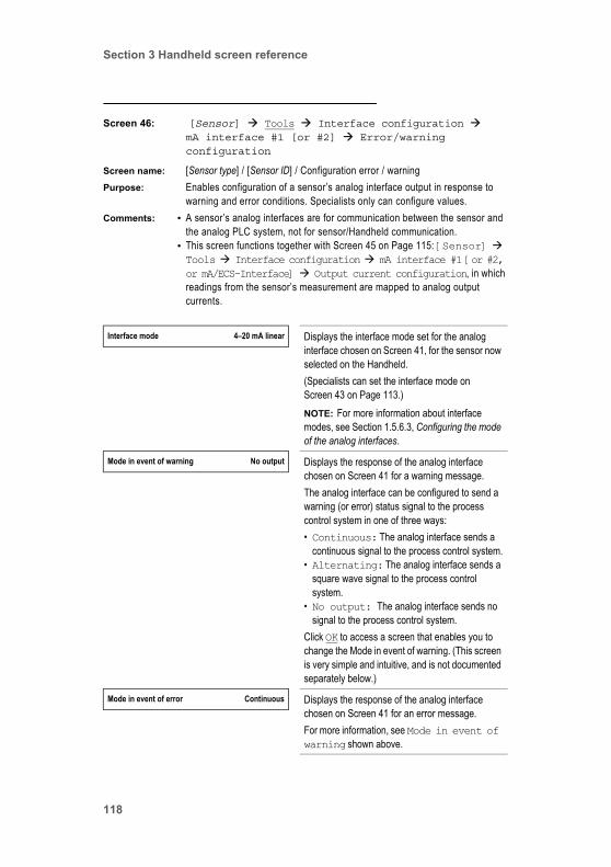
Section 3 Handheld screen reference
Screen 46: [Sensor] Tools Interface configuration mA interface #1 [or #2] Error/warning configuration
Screen name: [Sensor type] / [Sensor ID] / Configuration error / warningPurpose: Enables configuration of a sensor’s analog interface output in response to
warning and error conditions. Specialists only can configure values.Comments: • A sensor’s analog interfaces are for communication between the sensor and
the analog PLC system, not for sensor/Handheld communication.• This screen functions together with Screen 45 on Page 115: [Sensor] Tools Interface configuration mA interface #1 [or #2, or mA/ECS-Interface] Output current configuration, in which readings from the sensor’s measurement are mapped to analog output currents.
Interface mode 4–20 mA linear Displays the interface mode set for the analog interface chosen on Screen 41, for the sensor now selected on the Handheld.(Specialists can set the interface mode on Screen 43 on Page 113.)NOTE: For more information about interface modes, see Section 1.5.6.3, Configuring the mode of the analog interfaces.
Mode in event of warning No output Displays the response of the analog interface chosen on Screen 41 for a warning message.The analog interface can be configured to send a warning (or error) status signal to the process control system in one of three ways:• Continuous: The analog interface sends a
continuous signal to the process control system.• Alternating: The analog interface sends a
square wave signal to the process control system.
• No output: The analog interface sends no signal to the process control system.
Click OK to access a screen that enables you to change the Mode in event of warning. (This screen is very simple and intuitive, and is not documented separately below.)
Mode in event of error Continuous Displays the response of the analog interface chosen on Screen 41 for an error message. For more information, see Mode in event of warning shown above.
118
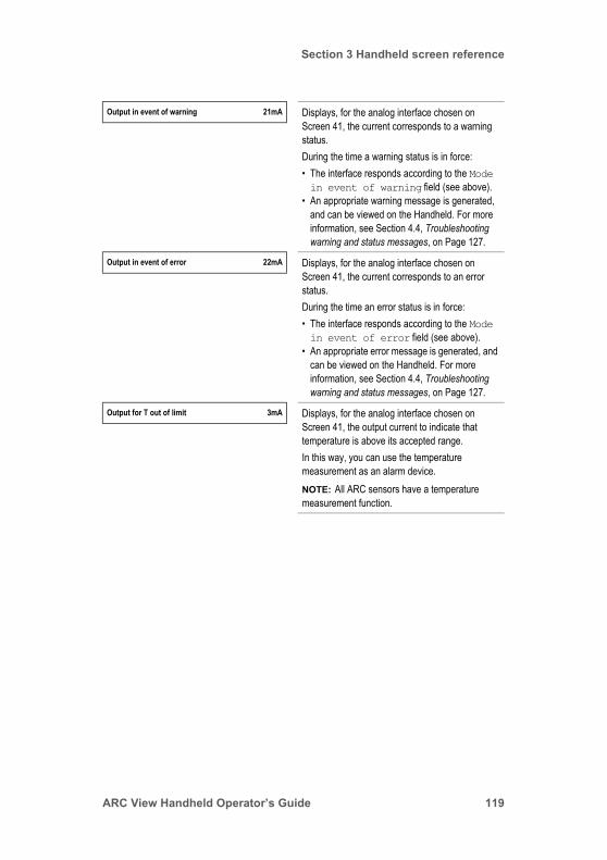
Section 3 Handheld screen reference
Output in event of warning 21mA Displays, for the analog interface chosen on Screen 41, the current corresponds to a warning status.During the time a warning status is in force:• The interface responds according to the Mode in event of warning field (see above).
• An appropriate warning message is generated, and can be viewed on the Handheld. For more information, see Section 4.4, Troubleshooting warning and status messages, on Page 127.
Output in event of error 22mA Displays, for the analog interface chosen on Screen 41, the current corresponds to an error status.During the time an error status is in force:• The interface responds according to the Mode in event of error field (see above).
• An appropriate error message is generated, and can be viewed on the Handheld. For more information, see Section 4.4, Troubleshooting warning and status messages, on Page 127.
Output for T out of limit 3mA Displays, for the analog interface chosen on Screen 41, the output current to indicate that temperature is above its accepted range. In this way, you can use the temperature measurement as an alarm device.NOTE: All ARC sensors have a temperature measurement function.
ARC View Handheld Operator’s Guide 119
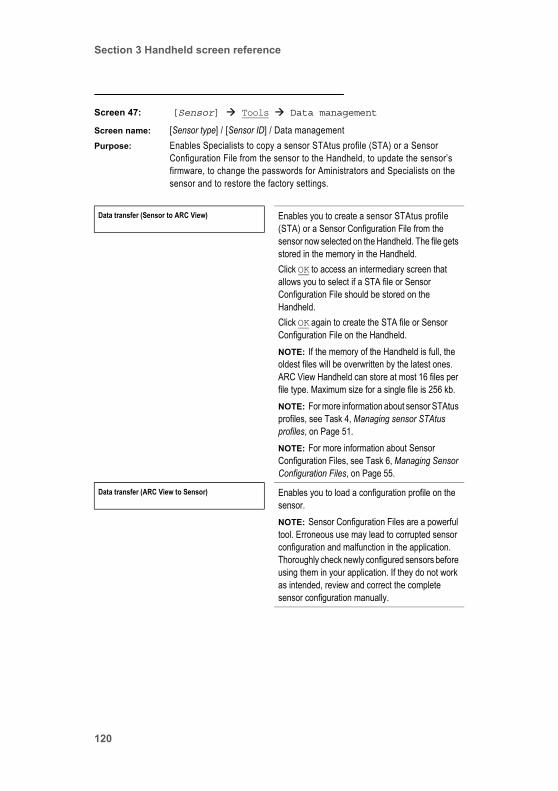
Section 3 Handheld screen reference
Screen 47: [Sensor] Tools Data management
Screen name: [Sensor type] / [Sensor ID] / Data managementPurpose: Enables Specialists to copy a sensor STAtus profile (STA) or a Sensor
Configuration File from the sensor to the Handheld, to update the sensor’s firmware, to change the passwords for Aministrators and Specialists on the sensor and to restore the factory settings.
Data transfer (Sensor to ARC View) Enables you to create a sensor STAtus profile (STA) or a Sensor Configuration File from the sensor now selected on the Handheld. The file gets stored in the memory in the Handheld.Click OK to access an intermediary screen that allows you to select if a STA file or Sensor Configuration File should be stored on the Handheld.Click OK again to create the STA file or Sensor Configuration File on the Handheld.NOTE: If the memory of the Handheld is full, the oldest files will be overwritten by the latest ones. ARC View Handheld can store at most 16 files per file type. Maximum size for a single file is 256 kb.NOTE: For more information about sensor STAtus profiles, see Task 4, Managing sensor STAtus profiles, on Page 51.NOTE: For more information about Sensor Configuration Files, see Task 6, Managing Sensor Configuration Files, on Page 55.
Data transfer (ARC View to Sensor) Enables you to load a configuration profile on the sensor.NOTE: Sensor Configuration Files are a powerful tool. Erroneous use may lead to corrupted sensor configuration and malfunction in the application. Thoroughly check newly configured sensors before using them in your application. If they do not work as intended, review and correct the complete sensor configuration manually.
120

Section 3 Handheld screen reference
Firmware update sensor Enables you to copy a firmware update file from a memory stick inserted in the Dock to a sensor.NOTE: The Handheld must be in the Dock, and a memory stick with a suitable file must also be inserted in the USB slot in the Dock.Click OK to perform the firmware update. Status screens keep you informed of progress.NOTE: For more information, see Appendix B.5, ARC sensor firmware update.
This field is shownonly when the
Handheld is in theDock.
Change password Enables you to change the password for operator level Administrator (A) or Specialist (S).Click OK to access a screen on which you can select one of the following:• Change password for A:
Click OK for a screen for entering the new password. You will be asked to enter the password a second time for confirmation.
• Change password for S: Click OK for a screen for entering the new password. You will be asked to enter the password a second time for confirmation.
Restore factory settings Enables you to set the ARC View Handheld back to factory settings.Click OK to access a screen on which you confirm that the configuration should be reset to factory settings.NOTE: If you restore the factory default settings, all settings you you customized on your device will be lost.For more information about restoring the factory settings, see Section 4.6, Restore Factory Settings, on Page 132.
ARC View Handheld Operator’s Guide 121

Section 3 Handheld screen reference
Screen 48: [Sensor] Tools Sensor info
Screen name: [Sensor type] / [Sensor ID] / Sensor infoPurpose: Enables access to manufacturing information uniquely identifying a sensor.
Enables Specialists to change the Sensor ID.Comments: • All operators can access this screen. However, only Specialists can change
the Sensor ID.• This screen is almost identical to Screen 22 on Page 84: [Sensor] View
Sensor info. The only difference is that here in screen 48, Specialists can change the Sensor ID.
Sensor ID 242450-3001 Displays a string identifying the sensor now selected on the Handheld. By default, the string is the sensor's part number followed by its serial number.Click OK to access a screen on which you can change the Sensor ID string. (This screen is very simple and intuitive, and is not documented separately below.)
All fields in the middle of the screen are the same as Screen 22 on Page 84: [Sensor] View Sensor info.
ARC Wi info Click OK to access a screen of information about the ARC Wi Sensor Adapter fitted to the sensor now selected on the Handheld.(The screen you open is Screen 46 on Page 118.)
This field is displayedonly when the sensor
selected on theHandheld is
communicating withthe Handheld inwireless mode.
122

Section 3 Handheld screen reference
Screen 49: [Sensor] Tools Sensor info ARC Wi info
Screen name: [Sensor type] / [Sensor ID] / ARC Wi infoPurpose: Enables access to manufacturing information uniquely identifying an ARC Wi
Sensor Adapter. No fields can be modified by operators. Comments: • This screen is available only when the sensor selected on the Handheld is
communicating with the Handheld in wireless mode. Wireless mode is in force when the Handheld is not in the Dock, assuming that default wireless settings are in operation. (See the Wireless settings field on Screen 15, Page 75.)
• All operators can access this screen.
ARC Wi firmware version WI0MS006 Displays the version of the firmware currently loaded on the printed circuit board of the ARC Wi Sensor Adapter connected to the sensor selected on the Handheld.For information about updating firmware, see Appendix B.5, ARC sensor firmware update, on Page 143.
ARC WiRF address 59560115 Displays the ARC hardware address of the radio module in the ARC Wi Sensor Adapter connected to the sensor selected on the Handheld.This value is set in the factory and cannot be changed.
Serial number 0015 Displays the serial number of the ARC Wi Sensor Adapter connected to the sensor selected on the Handheld.This value is set in the factory, and cannot be changed.
Workorder number 2091323 Displays the workorder number of the ARC Wi Sensor Adapter connected to the sensor selected on the Handheld. This number can be useful in tracing faulty ARC Wi Sensor Adapters to production runs.This value is set in the factory and cannot be changed.
Part number 242170/80 Displays the part number of the ARC Wi Sensor Adapter connected to the sensor selected on the Handheld.
Productname ARC WI Displays the product name of the ARC Wi Sensor Adapter connected to the sensor selected on the Handheld.
ARC View Handheld Operator’s Guide 123

Section 3 Handheld screen reference
Serial number PCB 0327615 Displays the serial number of the printed circuit board in the ARC Wi Sensor Adapter connected to the sensor selected on the Handheld.This value is set in the factory, and cannot be changed.
RF frequency 2.4245 GHz Displays the active communication frequency.
124
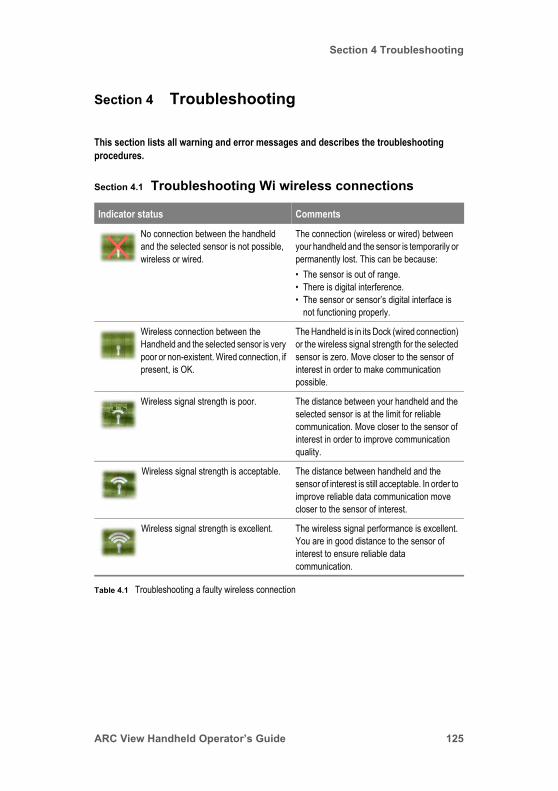
Section 4 Troubleshooting
Section 4 Troubleshooting
This section lists all warning and error messages and describes the troubleshooting procedures.
Section 4.1 Troubleshooting Wi wireless connections
Indicator status Comments
No connection between the handheld and the selected sensor is not possible, wireless or wired.
The connection (wireless or wired) between your handheld and the sensor is temporarily or permanently lost. This can be because:• The sensor is out of range.• There is digital interference.• The sensor or sensor’s digital interface is
not functioning properly.
Wireless connection between the Handheld and the selected sensor is very poor or non-existent. Wired connection, if present, is OK.
The Handheld is in its Dock (wired connection) or the wireless signal strength for the selected sensor is zero. Move closer to the sensor of interest in order to make communication possible.
Wireless signal strength is poor. The distance between your handheld and the selected sensor is at the limit for reliable communication. Move closer to the sensor of interest in order to improve communication quality.
Wireless signal strength is acceptable. The distance between handheld and the sensor of interest is still acceptable. In order to improve reliable data communication move closer to the sensor of interest.
Wireless signal strength is excellent. The wireless signal performance is excellent. You are in good distance to the sensor of interest to ensure reliable data communication.
Table 4.1 Troubleshooting a faulty wireless connection
ARC View Handheld Operator’s Guide 125

Section 4 Troubleshooting
Section 4.2 Troubleshooting Handheld sensor status colors
Indicator status Comments
Status symbol on the Handheld for a sensor is green
The connectivity to the sensor is OK. The sensor is running correctly and has no warnings and errors.(Flashing green indicates that the Handheld is being updated now with data from a correctly-functioning sensor. This is normal.)
Status symbol on the Handheld for sensor is yellow
The connection to the sensor is OK. However, the sensor indicates some error or warning. To analyze the problem, go to [Sensor] View Sensor status. This screen indicates the reason for the yellow status symbol.Such a case is not communicated through the ARC Wi Sensor adapter.(Flashing yellow indicates that the Handheld is being updated with data from a sensor with a warning or error status.)
Status symbol on the Handheld for a sensor is red
The ARC View Handheld lost connection to the sensor due to one of the following reasons:• The wireless signal strength is low.• The ARC Wi Sensor Adapter has been removed from
the sensor.• The sensor is defective. In the first case, move closer to the sensor of interest.The latter cases are indicated, in addition, by a red light on the corresponding ARC Wi Sensor Adapter.
Table 4.2 Troubleshooting Handheld sensor status colors
126
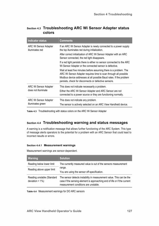
Section 4 Troubleshooting
Section 4.3 Troubleshooting ARC Wi Sensor Adapter status colors
Section 4.4 Troubleshooting warning and status messagesA warning is a notification message that allows further functioning of the ARC System. This type of message alerts operators to the potential for a problem with an ARC Sensor that could lead to incorrect results or errors.
Section 4.4.1 Measurement warnings
Measurement warnings are sensor-dependent.
Indicator status Comments
ARC Wi Sensor Adapter illuminates red
If an ARC Wi Sensor Adapter is newly connected to a power supply the top illuminates red during initialization.After correct initialization of ARC Wi Sensor Adapter with an ARC Sensor connected, the red light disappears.If a red light persists there is either no sensor connected to the ARC Wi Sensor Adapter or the connected sensor is defective.Wait at least five minutes before assuming there is a problem. The ARC Wi Sensor Adapter requires time to scan through all possible Modbus device addresses at all possible Baud rates. If the problem persists, check for disconnects or defective sensors.
ARC Wi Sensor Adapter does not illuminate
This does not indicate necessarily a problem.Either the ARC Wi Sensor Adapter and ARC Sensor are not connected to a power source or they are functioning normally.
ARC Wi Sensor Adapter illuminates green
This does not indicate any problem.The sensor is actively selected on an ARC View Handheld device.
Table 4.3 Troubleshooting with status colors on the ARC Wi Sensor Adapter
Warning Solution
Reading below lower limit The currently measured value is out of the sensors measurement range. You are using the sensor off-specification.
Reading above upper limit
Reading unstable (Standard deviation > 1%)
The sensor detects instability in measurement value. This can be the case if the sensing element is approaching end of life or if the current measurement conditions are unstable.
Table 4.4 Measurement warnings for DO ARC sensors
ARC View Handheld Operator’s Guide 127

Section 4 Troubleshooting
Section 4.4.2 Calibration warnings
Calibration warnings are sensor-dependent.
Section 4.4.3 Calibration status messages
T reading below lower limit (T < Tmin, chapter 5.8.1) The current temperature is out of the sensors temperature
measurement range.T reading above upper limit (T > Tmax, chapter 5.8.1)
T reading unstable (Standard deviation > 1%)
The sensor detects instability in temperature measurement. This can be the case if the measurement conditions are unstable.
Warning Solution
Calibration recommended Perform a calibration in order to ensure reliable measurement.
Last calibration not successful
The last calibration at either calibration point failed. The sensor is using the last successful calibration. In order to ensure reliable measurement perform a calibration.
Replace sensor cap (DO only)
The sensor cap of VISIFERM DO ARC must be replaced and the sensor needs to be recalibrated with the new cap.
Table 4.5 Calibration warnings for ARC sensors
Message Solution
Calibration Point 1(2): Below calibration range
The measurement value is below/above the lower/upper limit of the sensors allowed calibration range. Ensure stable measurement conditions and correct standards for calibration.
Calibration Point 1(2): Above calibration range
Calibration Point 1(2): Temperature too low
The measured temperature of your calibration standard is not in the allowed range for calibration. To perform successful calibration ensure stable measurement conditions within the calibration range of the corresponding sensor.
Calibration Point 1(2): Temperature too high
Table 4.6 Calibration status messages for ARC sensors
Warning Solution
Table 4.4 Measurement warnings for DO ARC sensors
128
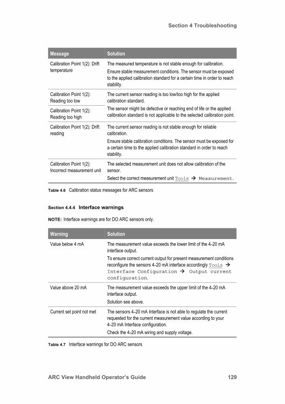
Section 4 Troubleshooting
Section 4.4.4 Interface warnings
NOTE: Interface warnings are for DO ARC sensors only.
Calibration Point 1(2): Drift temperature
The measured temperature is not stable enough for calibration. Ensure stable measurement conditions. The sensor must be exposed to the applied calibration standard for a certain time in order to reach stability.
Calibration Point 1(2): Reading too low
The current sensor reading is too low/too high for the applied calibration standard.The sensor might be defective or reaching end of life or the applied calibration standard is not applicable to the selected calibration point.
Calibration Point 1(2): Reading too high
Calibration Point 1(2): Drift reading
The current sensor reading is not stable enough for reliable calibration.Ensure stable calibration conditions. The sensor must be exposed for a certain time to the applied calibration standard in order to reach stability.
Calibration Point 1(2): Incorrect measurement unit
The selected measurement unit does not allow calibration of the sensor. Select the correct measurement unit Tools Measurement.
Warning Solution
Value below 4 mA The measurement value exceeds the lower limit of the 4–20 mA interface output.To ensure correct current output for present measurement conditions reconfigure the sensors 4–20 mA interface accordingly Tools Interface Configuration Output current configuration.
Value above 20 mA The measurement value exceeds the upper limit of the 4–20 mA interface output.Solution see above.
Current set point not met The sensors 4–20 mA Interface is not able to regulate the current requested for the current measurement value according to your 4–20 mA Interface configuration.Check the 4–20 mA wiring and supply voltage.
Table 4.7 Interface warnings for DO ARC sensors
Message Solution
Table 4.6 Calibration status messages for ARC sensors
ARC View Handheld Operator’s Guide 129
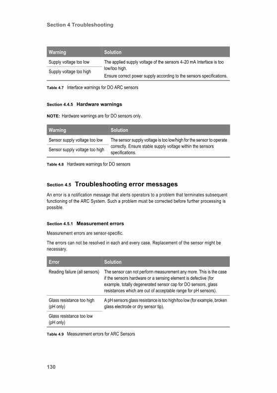
Section 4 Troubleshooting
Section 4.4.5 Hardware warnings
NOTE: Hardware warnings are for DO sensors only.
Section 4.5 Troubleshooting error messagesAn error is a notification message that alerts operators to a problem that terminates subsequent functioning of the ARC System. Such a problem must be corrected before further processing is possible.
Section 4.5.1 Measurement errors
Measurement errors are sensor-specific.
The errors can not be resolved in each and every case. Replacement of the sensor might be necessary.
Supply voltage too low The applied supply voltage of the sensors 4–20 mA Interface is too low/too high. Ensure correct power supply according to the sensors specifications.
Supply voltage too high
Warning Solution
Sensor supply voltage too low The sensor supply voltage is too low/high for the sensor to operate correctly. Ensure stable supply voltage within the sensors specifications.Sensor supply voltage too high
Table 4.8 Hardware warnings for DO sensors
Error Solution
Reading failure (all sensors) The sensor can not perform measurement any more. This is the case if the sensors hardware or a sensing element is defective (for example, totally degenerated sensor cap for DO sensors, glass resistances which are out of acceptable range for pH sensors).
Glass resistance too high (pH only)
A pH sensors glass resistance is too high/too low (for example, broken glass electrode or dry sensor tip).
Glass resistance too low (pH only)
Table 4.9 Measurement errors for ARC Sensors
Warning Solution
Table 4.7 Interface warnings for DO ARC sensors
130
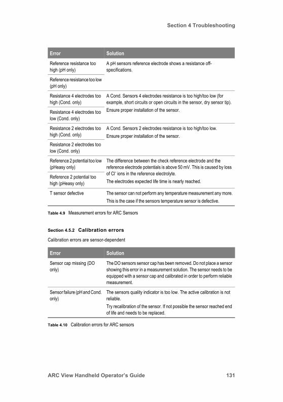
Section 4 Troubleshooting
Section 4.5.2 Calibration errors
Calibration errors are sensor-dependent
Reference resistance too high (pH only)
A pH sensors reference electrode shows a resistance off-specifications.
Reference resistance too low (pH only)
Resistance 4 electrodes too high (Cond. only)
A Cond. Sensors 4 electrodes resistance is too high/too low (for example, short circuits or open circuits in the sensor, dry sensor tip).Ensure proper installation of the sensor.Resistance 4 electrodes too
low (Cond. only)
Resistance 2 electrodes too high (Cond. only)
A Cond. Sensors 2 electrodes resistance is too high/too low.Ensure proper installation of the sensor.
Resistance 2 electrodes too low (Cond. only)
Reference 2 potential too low (pHeasy only)
The difference between the check reference electrode and the reference electrode potentials is above 50 mV. This is caused by loss of Cl- ions in the reference electrolyte. The electrodes expected life time is nearly reached.
Reference 2 potential too high (pHeasy only)
T sensor defective The sensor can not perform any temperature measurement any more.This is the case if the sensors temperature sensor is defective.
Error Solution
Sensor cap missing (DO only)
The DO sensors sensor cap has been removed. Do not place a sensor showing this error in a measurement solution. The sensor needs to be equipped with a sensor cap and calibrated in order to perform reliable measurement.
Sensor failure (pH and Cond. only)
The sensors quality indicator is too low. The active calibration is not reliable.Try recalibration of the sensor. If not possible the sensor reached end of life and needs to be replaced.
Table 4.10 Calibration errors for ARC sensors
Error Solution
Table 4.9 Measurement errors for ARC Sensors
ARC View Handheld Operator’s Guide 131

Section 4 Troubleshooting
Section 4.5.3 Hardware errors
Hardware errors are for all sensor types.
Section 4.6 Restore Factory SettingsYou can restore ARC sensors and ARC View Handheld to its original factory default settings. In order to perform this procedure you must have the “S” - specialist access on the corresponding ARC device.
To restore the factory settings, go to [Sensor] Tools Data management Restore factory settings and click OK.
To restore the factory settings on ARC View Handhelt, go to ARC View Handheld Tools Settings Restore factory settings and click OK.
NOTE: If you restore the factory default settings, all settings you customized on the device will be lost.
Error Solution
Sensor supply voltage far too low (DO only)
The sensors supply voltage is smaller than 6 V. This is too low voltage for the sensor to operate correctly.
Sensor supply voltage far too high (DO only)
The sensors supply voltage is larger than 40 V. Operation under such conditions leads to permanent damage of the sensor.
Temperature reading far below min. (DO only)
The current temperature is at least 10 °C lower/higher than the VISIFERM DO ARC sensors specified minimum/maximum operating temperature.Operation of the sensor under such conditions leads to permanent damage of the sensor.
Temperature reading far above max. (DO only)
Internal communication failure (pH and Cond. only)
The sensors internal communication failed. The sensor might be running under conditions of too high temperature or might have a hardware problem.Ensure operation under conditions such as specified for the specific sensor in use.
Table 4.11 Hardware errors for ARC sensors
132

Appendix A ARC System components
Appendix A ARC System components
This section lists all components in the HAMILTON ARC System, all associated documentation, and all part numbers.
Appendix A.1 HAMILTON ARC System core componentsThe core components of the HAMILTON ARC System are:
• ARC View Handheld and Dock. You can find specifications for these items in Table A.1, ARC View Handheld specifications.
• Power supply for Handheld and Dock. This unit requires a power source of 100 to 240 V, and has adapters for standard power sockets in Europe, Great Britain, Australia and the USA.
• ARC Cable VP 8.This is a data and power cable between a sensor and the Dock.
ARC View Handheld Operator’s Guide 133

Appendix A ARC System components
• ARC Wi Sensor Adapter. P/N 242 170.This item is mounted between the VP head of an ARC sensor and the VP sensor cable. It provides the wireless communication between the ARC sensor and ARC View Handheld.You require a minimum of one Sensor Adapter (although typically many more) for each ARC System.
• ARC sensor.At least one ARC sensor (although typically many more) is required for an ARC System. You can find details of ARC sensors in Appendix A.3, HAMILTON ARC System additional components.For more information about the components required to set up a HAMILTON ARC System, see Appendix A.4, HAMILTON ARC System spare parts.
Appendix A.2 HAMILTON ARC View Handheld specifications
Parameter Value
Permissible operating temperature +5 to +45°C
Maximum transmitting power +0 dBm
Maximum data transmission rate 256 kbps
Communication protocol Modbus RTU
Frequency range 2.45 GHz (IEEE 802.15.4)
Maximum range in open area ~100 m
Maximum range in process environment ~20 m
Dimensions (W x D x H) 140 x 35 x 85 mm
Weight 340 g
Table A.1 ARC View Handheld specifications
134

Appendix A ARC System components
Appendix A.3 HAMILTON ARC System additional componentsDepending upon your ARC setup, you need a selection of the following components.
Power supply:• ARC View Dock power supply unit requirement• Continuous battery operation
100 to 240 V 9 h
Protection rating IP 67 (except ARC View Dock, power adapter, and VP 8 sensor cable)
USB interface On ARC View Dock
Component Part Number Comment
Easyferm Plus ARC 120 242 091
Easyferm Plus ARC 225 242 092
Easyferm Plus ARC 325 242 093
Easyferm Plus ARC 425 242 094
Polilyte Plus ARC 120 242 111
Polilyte Plus ARC 225 242 112
Polilyte Plus ARC 325 242 113
Polilyte Plus ARC 425 242 114
Easyferm Food ARC 120 242 120
Easyferm Food ARC 225 242 121
Easyferm Food ARC 325 242 122
Easyferm Food ARC 425 242 123
pHeasy ARC 120 242 154
pHeasy ARC 225 242 155
Table A.2 HAMILTON ARC System components
Parameter Value
Table A.1 ARC View Handheld specifications
ARC View Handheld Operator’s Guide 135

Appendix A ARC System components
Appendix A.4 HAMILTON ARC System spare partsThe following spare parts for HAMILTON ARC System are available.
Conducell 4 USF ARC 120 242 159
Conducell 4 USF ARC 225 242 160
Conducell 4 USF ARC 325 242 161
Conducell 4 USF ARC 425 242 162
VISIFERM DO ARC 120 242 163
VISIFERM DO ARC 225 242 164
VISIFERM DO ARC 325 242 165
VISIFERM DO ARC 425 242 166
ARC View Handheld Package 242 180
ARC Wi Sensor Adapter 242 170
Document Part Number Comment
ARC View Handheld 242 167
ARC View Handheld Dock 242 168
ARC Memory Stick 396 230
Accupack ARC View 242 057 For ARC View Handheld
Power supply 242 007 For ARC Handheld and Dock
ARC Cable VP8 242 176
Table A.3 HAMILTON ARC System spare parts
Component Part Number Comment
Table A.2 HAMILTON ARC System components
136

Appendix A ARC System components
Appendix A.5 HAMILTON ARC System documents
Depending upon your ARC process analytics setup, you need some or all of the following documents.
Document Part Number Comment
VISIFERM DO ARC Modbus RTU Programmer's Manual
624179 Describes in detail the VISIFERM DO ARC Modbus RTU interface.You require this document only if you must set up a PLC to operate with ARC sensors.
ARC Conductivity Sensor Modbus RTU Programmer’s Manual
624299
ARC pH Sensor Modbus RTU Programmer’s Manual
624300
ARC Sensor Configurator User Manual
624258 Describes in detail how to install and use the ARC Sensor Configurator freeware to calibrate, configure and test ARC sensors.
ARC pH Sensor Operating Instructions For the following:• EASYFERM PLUS ARC• EASYFERM FOOD ARC• POLILYTE PLUS ARC• PHEASY ARC
624263 Packed together with the sensor.Includes all details of sensor calibration.
CONDUCELL 4USF ARC Sensor Operating Instructions
624267 Packed together with the sensor.Includes all details of sensor calibration.
VISIFERM DO ARC Optical Oxygen Sensor Operating Instructions
624268 Packed together with the sensor.Includes all details of sensor calibration.
HAMILTON ARC System 691069 Marketing brochure for the HAMILTON ARC System. Contains a list of product names and order numbers.
Table A.4 HAMILTON ARC System documents
ARC View Handheld Operator’s Guide 137

Appendix A ARC System components
138

Appendix B ARC System firmware updates
Appendix B ARC System firmware updates
This section explains how to update the firmware of all ARC System components:
• Appendix B.2, Handheld firmware update• Appendix B.3, Handheld RF Module firmware update• Appendix B.4, Dock firmware update• Appendix B.5, ARC sensor firmware update• Appendix B.6, Wi Sensor Adapter firmware update
Appendix B.1 IntroductionFirmware updates are available by agreement with HAMILTON AG. Typically, updates are delivered by internet. You then copy them to a suitable memory stick which you place in the USB socket in the Dock.
Appendix B.2, Handheld firmware update, on Page 140 gives a good overview of firmware updating.
NOTE: • Updates can be performed only in wired configuration, in other words, with all devices connected by cable to the Dock.
• Perform updates on a tidy desktop in the laboratory or office, and not under process conditions.
• Strictly follow both the instructions on the Handheld screen, and the operating instructions in the sections following.
• Do not leave the system unattended during the update process.• While an update is running, do not manipulate the system:
Do not switch off power.Do not disconnect sensors or cables.Do not remove the Handheld from the Dock.Do not remove the USB stick.
• Before starting an update plug the USB stick containing the firmware files into the Dock. The USB stick must be FAT or FAT32 formatted, and must have no directory structure. Firmware files must be in the root folder. Only files which are valid for a the update type that you are performing are displayed by the ARC View Handheld.
ARC View Handheld Operator’s Guide 139

Appendix B ARC System firmware updates
Appendix B.2 Handheld firmware update
Figure D.1 Handheld firmware update
140
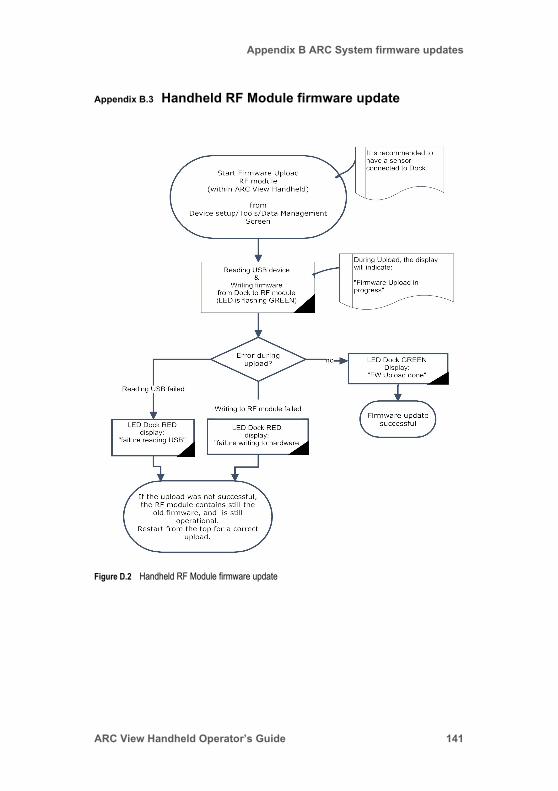
Appendix B ARC System firmware updates
Appendix B.3 Handheld RF Module firmware update
Figure D.2 Handheld RF Module firmware update
ARC View Handheld Operator’s Guide 141

Appendix B ARC System firmware updates
Appendix B.4 Dock firmware update
Figure D.3 Dock firmware update
142

Appendix B ARC System firmware updates
Appendix B.5 ARC sensor firmware update
Figure D.4 ARC sensor firmware update
ARC View Handheld Operator’s Guide 143

Appendix B ARC System firmware updates
Appendix B.6 Wi Sensor Adapter firmware update
Figure D.5 Wi Sensor Adapter firmware update
144
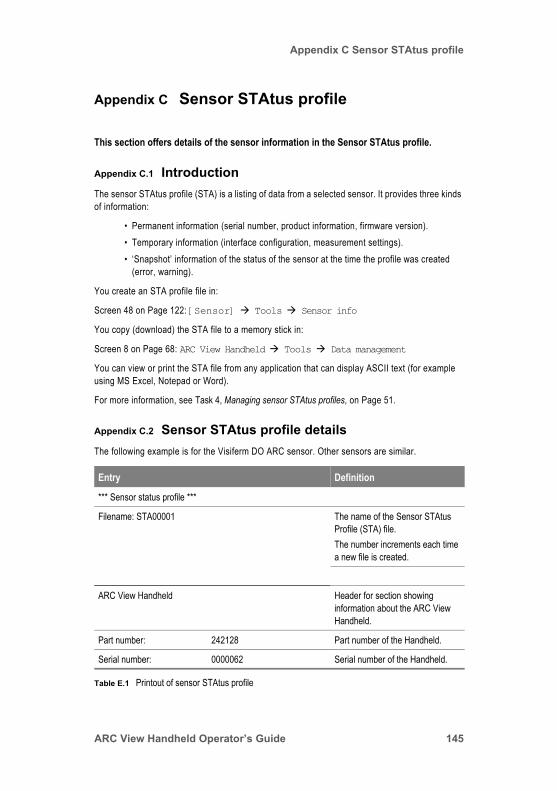
Appendix C Sensor STAtus profile
Appendix C Sensor STAtus profile
This section offers details of the sensor information in the Sensor STAtus profile.
Appendix C.1 IntroductionThe sensor STAtus profile (STA) is a listing of data from a selected sensor. It provides three kinds of information:
• Permanent information (serial number, product information, firmware version).• Temporary information (interface configuration, measurement settings).• ‘Snapshot’ information of the status of the sensor at the time the profile was created
(error, warning).
You create an STA profile file in:
Screen 48 on Page 122: [Sensor] Tools Sensor info
You copy (download) the STA file to a memory stick in:
Screen 8 on Page 68: ARC View Handheld Tools Data management
You can view or print the STA file from any application that can display ASCII text (for example using MS Excel, Notepad or Word).
For more information, see Task 4, Managing sensor STAtus profiles, on Page 51.
Appendix C.2 Sensor STAtus profile detailsThe following example is for the Visiferm DO ARC sensor. Other sensors are similar.
Entry Definition
*** Sensor status profile ***
Filename: STA00001 The name of the Sensor STAtus Profile (STA) file.The number increments each time a new file is created.
ARC View Handheld Header for section showing information about the ARC View Handheld.
Part number: 242128 Part number of the Handheld.
Serial number: 0000062 Serial number of the Handheld.
Table E.1 Printout of sensor STAtus profile
ARC View Handheld Operator’s Guide 145

Appendix C Sensor STAtus profile
RF address: 59568162 Radio frequency address of the Handheld. This is fixed for the Handheld, and is hardware dependent.
Firmware version: V022 16.04.2010 The version of the firmware loaded on the printed circuit board in the ARC View Handheld.
Date Time: 29.03.10 / 14:35 Date and time the sensor STAtus profile (STA) file was created.Date format is: DD.MM.YY.Time format is: HH:MM, 24-hour clock.
Operator Level
Active operator level: S U, A, S, D Operator level currently active in the sensor.For more information, see Section 1.5.2, ARC sensors: operator levels, on Page 19.
Sensor info Header for section showing information about the sensor detailed in the sensor STAtus profile (STA) file.
Product name: VISIFERM DO ARC Product name of the sensor. This field defines the type of the sensor.
Part number: 242163/01 Part number of the sensor.
Workorder number: 1383466 Number of the workorder under which the sensor was made. This serves as a further way of identifying the sensor.
Workorder date: 2009-12-02 Date of the workorder under which the sensor was made. Shown in format YYYY-MM-DD.
Serial number: 2029 Serial number of the sensor.
Entry Definition
Table E.1 Printout of sensor STAtus profile
146

Appendix C Sensor STAtus profile
Firmware version user end: ODOUM039 Version of the firmware currently loaded in the user end of the sensor. (“User end” refers to the communication electronics in the sensor.)For information about updating sensor software, see Appendix B.5, ARC sensor firmware update, on Page 143.
Firmware date user end: 2010-04-16 The date the firmware in the user end was created. (“User end” refers to the communication electronics in the sensor.)
Part number user end: 242998/04 Part number of the electronics in the user end. (“User end” refers to the communication electronics in the sensor.)
Serial number user end: 1207 Serial number of the electronics in the user end. (“User end” refers to the communication electronics in the sensor.)
Firmware version front end: not applicable Version of the firmware currently loaded in the front end. (“Front end” refers to the measurement electronics in the sensor.)NOTE: VISIFERM DO ARC sensors do not have a separate user end and front end. Instead, they have a single integrated unit. For this reason, “not applicable” is shown in this example. (However, this value is available for pH and conductivity sensors.)
Entry Definition
Table E.1 Printout of sensor STAtus profile
ARC View Handheld Operator’s Guide 147
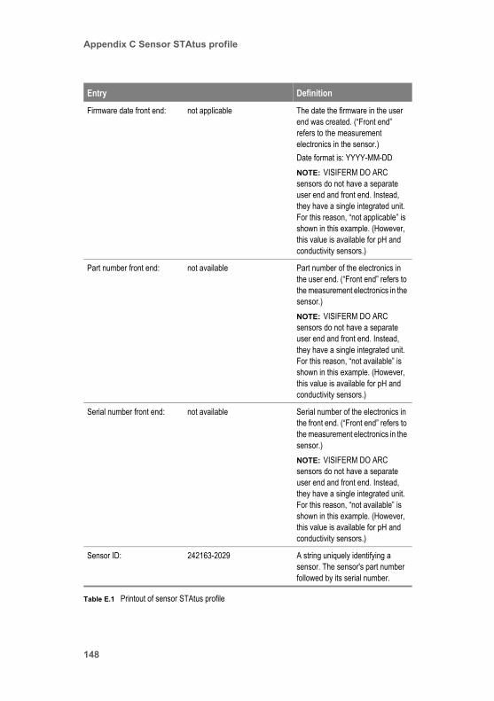
Appendix C Sensor STAtus profile
Firmware date front end: not applicable The date the firmware in the user end was created. (“Front end” refers to the measurement electronics in the sensor.)Date format is: YYYY-MM-DDNOTE: VISIFERM DO ARC sensors do not have a separate user end and front end. Instead, they have a single integrated unit. For this reason, “not applicable” is shown in this example. (However, this value is available for pH and conductivity sensors.)
Part number front end: not available Part number of the electronics in the user end. (“Front end” refers to the measurement electronics in the sensor.)NOTE: VISIFERM DO ARC sensors do not have a separate user end and front end. Instead, they have a single integrated unit. For this reason, “not available” is shown in this example. (However, this value is available for pH and conductivity sensors.)
Serial number front end: not available Serial number of the electronics in the front end. (“Front end” refers to the measurement electronics in the sensor.)NOTE: VISIFERM DO ARC sensors do not have a separate user end and front end. Instead, they have a single integrated unit. For this reason, “not available” is shown in this example. (However, this value is available for pH and conductivity sensors.)
Sensor ID: 242163-2029 A string uniquely identifying a sensor. The sensor's part number followed by its serial number.
Entry Definition
Table E.1 Printout of sensor STAtus profile
148
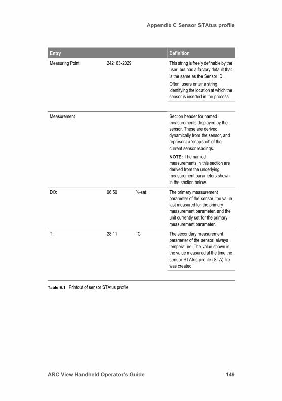
Appendix C Sensor STAtus profile
Measuring Point: 242163-2029 This string is freely definable by the user, but has a factory default that is the same as the Sensor ID. Often, users enter a string identifying the location at which the sensor is inserted in the process.
Measurement Section header for named measurements displayed by the sensor. These are derived dynamically from the sensor, and represent a ‘snapshot’ of the current sensor readings.NOTE: The named measurements in this section are derived from the underlying measurement parameters shown in the section below.
DO: 96.50 %-sat The primary measurement parameter of the sensor, the value last measured for the primary measurement parameter, and the unit currently set for the primary measurement parameter.
T: 28.11 °C The secondary measurement parameter of the sensor, always temperature. The value shown is the value measured at the time the sensor STAtus profile (STA) file was created.
Entry Definition
Table E.1 Printout of sensor STAtus profile
ARC View Handheld Operator’s Guide 149

Appendix C Sensor STAtus profile
Measurement Parameter Header for section showing details of the sensor’s underlying measurement parameters, from which the named measurements displayed by the sensor are derived. (Named measurements are shown in the sections above.)
Salinity: 0.00 mS/cm NOTE: This entry is found only for DO sensors.The salinity set for the sensor at the time the sensor STAtus profile (STA) file was created.NOTE: The unit delivered by the sensor is always the conductivity unit, mS/am.
Air pressure: 1013.00 mbar NOTE: This entry is found only for DO sensors.NOTE: The air pressure set for the environment of the sensor at the time the sensor STAtus profile (STA) file was created. (In other words, this is not necessarily the process pressure.)The unit delivered by the sensor is always the millibar.
Moving average: (auto) 30 none Moving average set for the sensor at the time the sensor STAtus profile (STA) file was created.For information about moving averages, see Section 1.5.8, ARC sensor measurements: moving average, on Page 32.“none” indicates that there are no units.
Entry Definition
Table E.1 Printout of sensor STAtus profile
150

Appendix C Sensor STAtus profile
Resolution: (auto) 16 none Resolution set for the sensor at the time the sensor STAtus profile (STA) file was created.For information about resolution, see Section 1.5.9, ARC sensor measurements: resolution, on Page 32.“none” indicates that there are no units.
Operating hours/counters Header for section showing details of:• Operating hours at different
temperatures.• Sensor event counters.• Operational limits.
Operating hours: 78.02 h Total number of sensor operating hours recorded by the sensor during its entire life. This value acts as a time stamp to mark the time at which the sensor STAtus profile (STA) file is created.
Operating hours > 85 °C: 0.00 h Total number of hours the sensor has operated above 85°C during its entire life.
Operating hours > 135 °C: 0.00 h Total number of hours the sensor has operated above 135°C during its entire life.
Number of SIP: 0 Total number of Sterilizations In Place that the sensor has undergone during its entire life.NOTE: For more information about SIPs, see Section 1.5.7, ARC sensors: Cleanings and Sterilizations In Place, on Page 31.
Entry Definition
Table E.1 Printout of sensor STAtus profile
ARC View Handheld Operator’s Guide 151
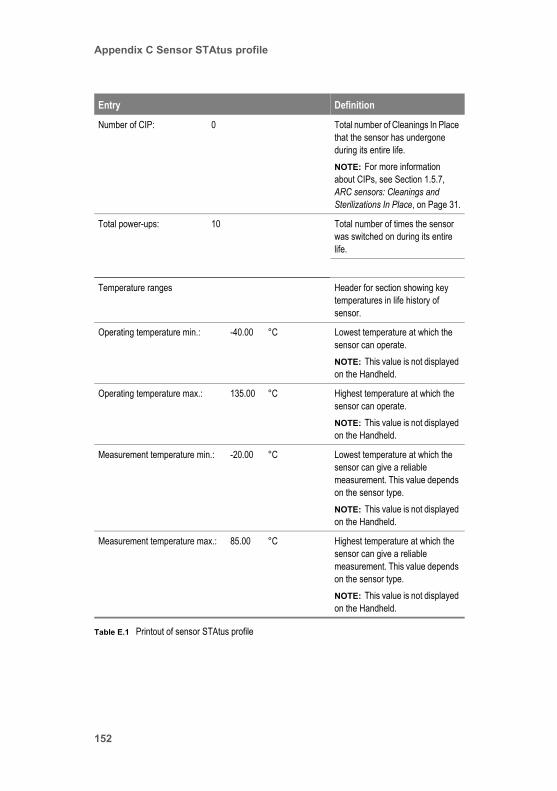
Appendix C Sensor STAtus profile
Number of CIP: 0 Total number of Cleanings In Place that the sensor has undergone during its entire life.NOTE: For more information about CIPs, see Section 1.5.7, ARC sensors: Cleanings and Sterilizations In Place, on Page 31.
Total power-ups: 10 Total number of times the sensor was switched on during its entire life.
Temperature ranges Header for section showing key temperatures in life history of sensor.
Operating temperature min.: -40.00 °C Lowest temperature at which the sensor can operate.NOTE: This value is not displayed on the Handheld.
Operating temperature max.: 135.00 °C Highest temperature at which the sensor can operate.NOTE: This value is not displayed on the Handheld.
Measurement temperature min.: -20.00 °C Lowest temperature at which the sensor can give a reliable measurement. This value depends on the sensor type.NOTE: This value is not displayed on the Handheld.
Measurement temperature max.: 85.00 °C Highest temperature at which the sensor can give a reliable measurement. This value depends on the sensor type.NOTE: This value is not displayed on the Handheld.
Entry Definition
Table E.1 Printout of sensor STAtus profile
152

Appendix C Sensor STAtus profile
Calibration temperature min.: 0.00 °C Lowest temperature at which the sensor can be calibrated. This value depends on the sensor type.NOTE: This value is not displayed on the Handheld.
Calibration temperature max.: 60.00 °C Highest temperature at which the sensor can be calibrated. This value depends on the sensor type.NOTE: This value is not displayed on the Handheld.
Warnings Header for section showing any warnings in force at the time this sensor STAtus profile (STA) file was created.
none For information, see Section 4.4, Troubleshooting warning and status messages, on Page 127.
Errors Header for section showing any errors in force at the time this sensor STAtus profile (STA) file was created.
none For information see Section 4.5, Troubleshooting error messages, on Page 130.
Entry Definition
Table E.1 Printout of sensor STAtus profile
ARC View Handheld Operator’s Guide 153

Appendix C Sensor STAtus profile
Quality Header for section showing quality of sensor reading at the time this sensor STAtus profile (STA) file was created.
Quality indicator: 97% excellent An indicator of the quality of the sensor reading. This is expressed on the handheld as: excellent, good, acceptable, poor, very poor, defective. However, in this sensor STAtus profile (STA) file, the percentage value of the quality indicator is also shown.For information, see:• Section 1.5.11, on Page 34.• Screen 20 on Page 80.
SIP/CIP Definition Header for section showing the upper and lower temperature limits for Sterilizations In Place (SIPs) and Cleanings in Place (CIPs). These limits define the conditions used by the sensor to recognize a SIP or a CIP.NOTE: The temperature unit is always °C.For more information, see Section 1.5.7, on Page 31.
SIP min. temperature: 120 lower limit of temp. range / °C Minimum temperature at which a Sterilization In Place is recognized by the sensor. SIPs below this temperature are not counted.
SIP max. temperature: 135 upper limit of temp. range / °C Maximum temperature at which a Sterilization In Place is recognized by the sensor. SIPs above this temperature are not counted.
Entry Definition
Table E.1 Printout of sensor STAtus profile
154

Appendix C Sensor STAtus profile
SIP min. time span: 20 min. time in temp. range / min Minimum time period over which a Sterilization In Place event is recognized by the sensor. SIPs that take place over a shorter period are not counted.
CIP min. temperature: 80 lower limit of temp. range / °C Minimum temperature at which a Cleaning In Place is recognized by the sensor. CIPs below this temperature are not counted.
CIP max. temperature: 100 upper limit of temp. range / °C Maximum temperature at which a Cleaning In Place is recognized by the sensor. CIPs above this temperature are not counted.
CIP min. time span: 20 min. time in temp. range / min Minimum time period over which a Cleaning In Place event is recognized by the sensor. CIPs that take place over a shorter period are not counted.
Configuration digital interface Header for section showing configuration details of the sensor’s digital interface.For information, see Digital RS485 Modbus RTU interface, on Page 1-18.
Modbus address 1 Modbus address
Baud rate: 19200 bit/sec Baud rate of the digital RS485 interface on the sensor that was selected at the time this sensor STAtus profile (STA) file was created.For information, see Section 1.5.5.3, Baud rates.
Parity: none none,even,odd Parity status of the digital RS485 interface on the sensor that was selected at the time this sensor STAtus profile (STA) file was created.
Entry Definition
Table E.1 Printout of sensor STAtus profile
ARC View Handheld Operator’s Guide 155

Appendix C Sensor STAtus profile
Stop bits: 2 1,2 Number of stop bits set for the digital RS485 interface on the sensor that was selected at the time this sensor STAtus profile (STA) file was created. (This value is required for programming the PLC.) Operators cannot change this status.
Configuration analog interfaceSection showing the configuration of the analog interface that was selected on the sensor at the time this sensor STAtus profile (STA) file was created.
Analog interface 1: mA/ECS-Interface Name of analog interface that was selected on the sensor at the time this file was created. This can be Analog interface 1 or Analog interface 2.For information, see Analog interfaces, on Page 1-17.
Output mode: 4–20 mA linear Output mode in force on the analog interface of the sensor at the time this file was created.For information, see Table 1.6, Explanation of interface modes configured on [Sensor] à Tools à Interface configuration à mA interface #1 [or #2, or mA/ECS-Interface] à Interface mode, on Page 28.
4–20 mA output Header for section showing the configuration of the analog interface that was selected on the sensor at the time this file was created.
Entry Definition
Table E.1 Printout of sensor STAtus profile
156

Appendix C Sensor STAtus profile
4–20 mA measurement channel: DO The named measurement configured for Analog Interface 1 at the time this sensor STAtus profile (STA) file was created.There are three possibilities:• Cond = Conductivity• pH = pH• DO = Dissolved oxygen
Measurement value at 4 mA: 0 %-sat Measurement values configured to correspond to outputs of 4 mA, 12 mA, and 20 mA from the analog interface selected at the time this file was created. In this file, an output of 4 mA indicates a value of 0%-sat, 12 mA indicates 150%-sat, and 20mA indicates 300%-sat.For more information, see Section 1.5.6.3, Configuring the mode of the analog interfaces, on Page 27.
Measurement value at 12 mA: 150 %-sat
Measurement value at 20 mA: 300 %-sat
Unit of measurement: %-sat Unit of measurement configured for the sensor at the time this file was created.
Fixed test value: 10 mA Value configured for the analog interface test signal at the time this file was created.
Mode in event of warning: No output Modes configured for the analog interface signal in event of warnings and errors, at the time this file was created.
Mode in event of error: Continuous
Output in event of warning: 3.5 mA Output currents configured for the analog interface signal in event of warnings and errors, at the time this file was created.
Output in event of error: 3.5 mA
Output for T out of limit: 3.5 mA Output current configured for the analog interface signal to indicate that temperature is above its accepted range.
Entry Definition
Table E.1 Printout of sensor STAtus profile
ARC View Handheld Operator’s Guide 157

Appendix C Sensor STAtus profile
Active output signal: 12.2 mA Current being output by the analog interface at the time this file was created.
ECS Output NOTE: This section is for VISIFERM DO sensors only (Not available for VISIFERM DO ARC).Header for section showing details of electro-chemical sensor simulation output from the analog interface.
Current in zero oxygen(+25°C): 0 nA Output current configured to be delivered by the analog interface when in ECS simulation mode, when in zero oxygen, at the time this file was created.NOTE: The unit is always nA.
Current in air(+25°C): 60 nA Output current configured to be delivered by the analog interface when in ECS simulation mode, when in air, at the time this file was created.NOTE: The unit is always nA.
Temperatur coefficient: 3.1 %/K
Fixed test value: 100 nA Value configured for the analog interface test signal, when in ECS simulation mode, at the time this file was created.NOTE: The unit is always nA.
Mode in event of warning: No output Modes configured for the analog interface signal, when the interface is in ECS mode, in event of warnings and errors, at the time this file was created.
Mode in event of error: Continuous
Entry Definition
Table E.1 Printout of sensor STAtus profile
158

Appendix C Sensor STAtus profile
Output in event of warning: 522 nA Output currents configured for the analog interface signal, when the interface is in ECS simulation mode, in event of warnings and errors, at the time this file was created.
Output in event of error: 544 nA
Output for T out of limit: 566 nA Output current configured for the analog interface signal, when in ECS simulation mode, to indicate that temperature is above its accepted range.
Active output signal: 0 nA Current being output by the analog interface, if in ECS mode, at the time this file was created.
Calibration Header for section showing details of last sensor calibration.
Phase in zero oxygen (+25°C): 70.68 ° For dissolved oxygen sensors, the underlying primary parameter is the phase difference between the excitation source and fluorescent signals, as shown in the example here. The DO reading is derived from this phase difference.
Stern-Volmer coefficient (+25°C): 0.0241 none Value of the Stern-Vomer coefficient at the last calibration of the sensor. NOTE: “none” indicates that there are no units.
Calibration Temperature: 25 °C The temperature at which the last calibration of the sensor took place.
Calibration data: point 1 Header for section showing values and units measured for the primary parameter at the Calibration data: point 1 stage of the sensor’s last calibration.
Entry Definition
Table E.1 Printout of sensor STAtus profile
ARC View Handheld Operator’s Guide 159
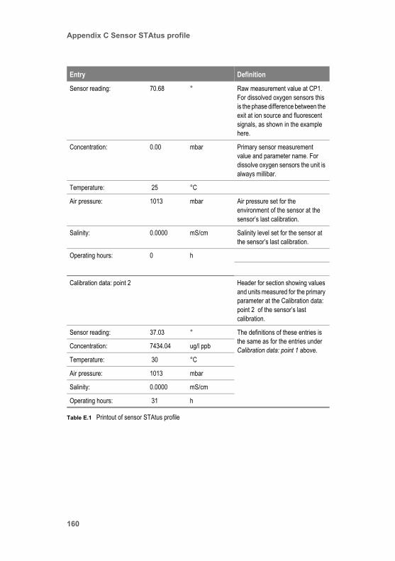
Appendix C Sensor STAtus profile
Sensor reading: 70.68 ° Raw measurement value at CP1. For dissolved oxygen sensors this is the phase difference between the exit at ion source and fluorescent signals, as shown in the example here.
Concentration: 0.00 mbar Primary sensor measurement value and parameter name. For dissolve oxygen sensors the unit is always millibar.
Temperature: 25 °C
Air pressure: 1013 mbar Air pressure set for the environment of the sensor at the sensor’s last calibration.
Salinity: 0.0000 mS/cm Salinity level set for the sensor at the sensor’s last calibration.
Operating hours: 0 h
Calibration data: point 2 Header for section showing values and units measured for the primary parameter at the Calibration data: point 2 of the sensor’s last calibration.
Sensor reading: 37.03 ° The definitions of these entries is the same as for the entries under Calibration data: point 1 above.Concentration: 7434.04 ug/l ppb
Temperature: 30 °C
Air pressure: 1013 mbar
Salinity: 0.0000 mS/cm
Operating hours: 31 h
Entry Definition
Table E.1 Printout of sensor STAtus profile
160

Index
Index
Numerics4-20 mA bilinear field on Handheld’s interface 30, 1154-20 mA fixed field on Handheld’s interface 28, 1144-20 mA linear field on Handheld’s interface 29, 114
AAccupack ARC View part number 136Active output signal field on Handheld’s interface 91, 117adding a sensor to an ARC system 49addresses for Modbus 25Administrator
operator level, setting 41tasks 40
Air pressure field on Handheld’s interface 96, 104alarm device 93, 119analog interface 17
configuring 50configuring the mode of 27configuring the output current of 27mapping parameters to 27
ARC Cable VP 8part number of 136photograph of 9, 133
ARC Memory Stick part number 136ARC pH Sensor Operating Instructions document part number 137ARC sensor 134
analog interface 17analog interface configuration 26Baud rate 26calibrating 23, 41Cleanings and Sterilizations In Place 31communication with a computer 19communication with a PLC system 18communication with the Handheld 18communications 17digital interface configuration 25Easyferm Food ARC 135firmware update 143measurements, moving average 32operational status 20operator levels 19part numbers 135, 136pHeasy ARC 135Polilyte Plus ARC part numbers 135quality indicator 34reading basic parameter values from 38reading detailed data from 39reading information data 40reading interface configuration data 40reading status data 39
ARC View Handheld Operator’s Guide 161

Index
resolution 32setting up new sensor in an ARC system 49temperature compensation factor 34
ARC View Dockfirmware update for 142illustration of 9photograph of 133
ARC View Dock info field on Handheld’s interface 63ARC View Handheld
communication with 18complete list of screens 59Dock part number 136firmware update 140full details of screens 61illustration of 9keys and interface 11overview 9Package part number 136part number 136photograph of 133power management 16RF module firmware update 141setting up 10settings, managing 47specifications 134status colors 21switching on and off 11system principles 17tasks tutorial 37
ARC Wi firmware version field on Handheld’s interface 123ARC Wi info field on Handheld’s interface 122ARC Wi Sensor Adapter
part number of 136photograph of 134status colors 22wireless settings 48
ARC WiRF address field on Handheld’s interface 123Assignment field on Handheld’s interface 109automatic standard calibration 42
Bbacklight switches off automatically 16battery status 13Baud rate 26
configuring 50Baud rate field on Handheld’s interface 65, 77, 86, 112
CCalibrate at point 1 field on Handheld’s interface 106Calibrate at point 2 field on Handheld’s interface 107Calibrate field on Handheld’s interface 100calibration 41
automatic standard 42
162

Index
configuring 51errors, troubleshooting 131of ARC sensors 23setting salinity for 96standards list 42status messages, troubleshooting 128warnings, troubleshooting 128
Calibration data field on Handheld’s interface 100Calibration data: point 1 field on Handheld’s interface 43, 45, 101Calibration data: point 2 field on Handheld’s interface 45, 101Calibration data: product field on Handheld’s interface 102Calibration field on Handheld’s interface 94Calibration point field on Handheld’s interface 103Cancel field on Handheld’s interface 109checking status of sensors in ARC system 37CIP max. temperature field on Handheld’s interface 99CIP min. temperature field on Handheld’s interface 99CIP min. time span field on Handheld’s interface 99CIP⁄SIP definition field on Handheld’s interface 97Cleanings In Place 31communication
between an ARC sensor and a computer 19of an ARC sensor with a PLC system 18with ARC sensors 17
Conducell 4 USF ARC 136part numbers 136
CONDUCELL 4USF ARC Sensor Operating Instructions document part number 137configuration
of analog interface 26of Baud rate 50of calibration procedure 51of errors and warnings 30of Modbus device address 50of the analog interface 50
Connected Sensors field on Handheld’s interface 76, 77Connectivity field on Handheld’s interface 62, 66
DData management field on Handheld’s interface 66, 94Data transfer (ARC View to USB device) field on Handheld’s interface 68, 69Data transfer (Sensor to ARC View) field on Handheld’s interface 120date settings, adjusting 47device addresses 25Device info field on Handheld’s interface 62, 65digital interface configuration of ARC sensors 25Digital RS485 field on Handheld’s interface 85, 110Digital RS485 Modbus RTU interface 18Display settings field on Handheld’s interface 75Dock
firmware update for 142illustration of 9photograph of 133
ARC View Handheld Operator’s Guide 163

Index
Down Key 14
EEasyferm Food ARC part numbers 135Easyferm Plus ARC part numbers 135equipment warnings 8Error⁄warning configuration field on Handheld’s interface 88, 89, 113errors
troubleshooting calibration errors 131troubleshooting hardware errors 132troubleshooting measurement errors 130
errors and warnings, configuring 30Errors: calibration field on Handheld’s interface 82Errors: hardware field on Handheld’s interface 82Errors: interface field on Handheld’s interface 82Errors: measurement field on Handheld’s interface 82
Ffirmware update
ARC sensor firmware 143Dock 142Handheld 140Handheld RF module 141Wi Sensor Adapter 144
Firmware update ARC Dock field on Handheld’s interface 69Firmware update ARC View field on Handheld’s interface 69Firmware update ARC Wi field on Handheld’s interface 70Firmware update RF module field on Handheld’s interface 69Firmware update sensor field on Handheld’s interface 121Firmware version field on Handheld’s interface 62, 64, 84
GGraph field on Handheld’s interface 78, 95
HHAMILTON ARC System document part number 137Handheld
firmware update 140overview 9Package part number 136photograph of 133RF module firmware update 141settings, managing 47specifications 134tasks tutorial 37
hardwareerrors, troubleshooting 132warnings, troubleshooting 130
IInitial measurement field on Handheld’s interface 108
164

Index
interface 11RS485 18
Interface configuration field on Handheld’s interface 78, 94Interface mode field on Handheld’s interface 87, 88, 90, 92, 113, 115, 118interface warnings, troubleshooting 129
Kkeys 11
Down Key 14Left Key 14Right Key 14Up Key 14
LLeft Key 14
MmA interface #1 field on Handheld’s interface 86, 111mA interface #2 field on Handheld’s interface 86, 111mA/ECS-Interface field on Handheld’s interface 86manufacturing information for a sensor 84, 122, 123Measured value field on Handheld’s interface 103measurement
errors, troubleshooting 130warnings, troubleshooting 127
Measurement data field on Handheld’s interface 95Measurement field on Handheld’s interface 93Measurement variable field on Handheld’s interface 90, 116Memory Stick part number 136Modbus device address field on Handheld’s interface 87, 112Modbus device addresses 25
configuring 50Mode in event of error field on Handheld’s interface 92, 118Mode in event of warning field on Handheld’s interface 92, 118moving average 32Moving average field on Handheld’s interface 97
NNumber of CIP field on Handheld’s interface 83Number of power ups field on Handheld’s interface 83Number of SIP field on Handheld’s interface 83
OOFF field on Handheld’s interface 28, 114Operating hours > 135°C field on Handheld’s interface 83Operating hours > 85°C field on Handheld’s interface 83Operating hours field on Handheld’s interface 104operational status 20operator levels 12, 19Output current configuration field on Handheld’s interface 88, 89, 113
ARC View Handheld Operator’s Guide 165

Index
Output for T out of limit field on Handheld’s interface 93, 119Output in event of error field on Handheld’s interface 93, 119Output in event of warning field on Handheld’s interface 119Output in event of warning field on Handheld’s interface 93
Ppanel
for device 13for sensor 13, 14
Parity field on Handheld’s interface 87, 112part number
Accupack ARC View 136ARC Cable VP 8 136ARC Memory Stick 136ARC pH Sensor Operating Instructions document 137ARC View Handheld 136ARC Wi Sensor Adapter 136Conducell 4 USF ARC 136Easyferm Food ARC 135Easyferm Plus ARC 135Memory Stick 136pHeasy 135Polilyte Plus ARC 135VISIFERM DO ARC 136
Part number field on Handheld’s interface 63, 64, 84, 123pHeasy ARC part numbers 135photograph of 134Polilyte Plus ARC part numbers 135power management 16
backlight switches off automatically 16Handheld switches off automatically 16reset Handheld 16switch off Handheld 16switch on Handheld 16wake up Handheld when backlight switched off 16
Power settings field on Handheld’s interface 75power supply
for Handheld and Dock, photograph of 133illustration of 9part number 136
primary sensor parameter 15product calibration
calibrating for product 44Product calibration field on Handheld’s interface 107Product name field on Handheld’s interface 84Productname field on Handheld’s interface 63, 64, 123
Qquality indicator 34Quality indicator field on Handheld’s interface 80
166

Index
Rreading
basic parameter values from a sensor 38detailed data from a sensor 39
reset Handheld 16resolution 32Resolution field on Handheld’s interface 97RF address field on Handheld’s interface 64RF modul info field on Handheld’s interface 63RF module firmware version field on Handheld’s interface 63Right Key 14
Ssafety notices 7Salinity field on Handheld’s interface 96, 104salinity, setting for calibration 96secondary sensor parameter 13Select standard set field on Handheld’s interface 107Sensitivity (25°C) field on Handheld’s interface 105sensor
calibrating 41calibration standards list 42checking status of 37manufacturing information 84, 122, 123number 12reading information about 40reading interface configuration data 40reading status data 39setting up new sensor in an ARC system 49status of 37STAtus profile details 145
Sensor Adapter part number 136Sensor ID 13, 49Sensor ID field on Handheld’s interface 84, 122Sensor info field on Handheld’s interface 78, 94sensor panel 13, 14sensor parameter
primary 15secondary 13
sensor part numbersConducell 4 USF ARC 136Easyferm Food ARC 135Easyferm Plus ARC 135pHeasy 135Polilyte Plus ARC 135VISIFERM DO ARC 136
Sensor status field on Handheld’s interface 78, 94Sensor status profile field on Handheld’s interface 70, 71Sensors connected field on Handheld’s interface 65, 76, 77Serial number end user field on Handheld’s interface 85Serial number field on Handheld’s interface 62, 64, 84, 123Serial number front end field on Handheld’s interface 85
ARC View Handheld Operator’s Guide 167

Index
Serial number PCB field on Handheld’s interface 63, 64, 124Set date field on Handheld’s interface 74Set time field on Handheld’s interface 74setting up the ARC View Handheld 10settings
for ARC wireless 48for date 47for Handheld, managing 47for time 47
Settings field on Handheld’s interface 66SIP max. temperature field on Handheld’s interface 98SIP min. temperature field on Handheld’s interface 98SIP min. time span field on Handheld’s interface 99Specialist operator level
setting 46tasks 46
STA file details 145Standard set field on Handheld’s interface 102standards list 42status colors
understanding them on the Handheld 21understanding them on the Wi Sensor Adapter 22
status of Wi connection 125STAtus profiles
creating 52downloading 52managing 51reading 53
status symbol for ARC Wi Sensor Adaptergreen 127no illumination 127red 127
status symbol for Handheldfor empty panel 14for sensor 15green 37, 126green flashing 126red 126red flashing 126yellow 126yellow flashing 126
Sterilizations In Place 31Stop bits field on Handheld’s interface 87, 112switching on and off 11
backlight switches off automatically 16Handheld switches off automatically 16reset Handheld 16switch off handheld 16switch on Handheld 16wake up Handheld when backlight switched off 16
symbolsbattery status 13operator level 12Sensor ID 13
168

Index
sensor number 12status symbol for empty panel 14status symbol for sensor 15wireless connection status 12
system principles 17
Ttasks
Administrator 40Specialist 46tutorial 37User 37
Temp. comp. factor field on Handheld’s interface 96temperature compensation factor 34Temperature field on Handheld’s interface 104temperature measurement 93, 119time settings, adjusting 47Total operating hours field on Handheld’s interface 80, 83troubleshooting
calibration errors 131calibration status messages 128calibration warnings 128hardware errors 132hardware warnings 130interface warnings 129measurement errors 130measurement warnings 127Wi wireless connection 125
tutorial of Handheld tasks 37typographic standards in this manual 8
UUnit for DO field on Handheld’s interface 95Unit for T field on Handheld’s interface 95Up Key 14USB stick part number 136User tasks 37
VValue at 20 mA field on Handheld’s interface 91, 117Value at 4 mA field on Handheld’s interface 91, 116VISIFERM DO ARC Modbus RTU Programmer’s Manual document part number 137VISIFERM DO ARC Optical Oxygen Sensor Operating Instructions document part number 137VISIFERM DO ARC part numbers 136
Wwarnings
for calibration, troubleshooting 128for equipment 8for hardware, troubleshooting 130for interface, troubleshooting 129for measurement, troubleshooting 127
ARC View Handheld Operator’s Guide 169
Index
Warnings: calibration field on Handheld’s interface 81Warnings: hardware field on Handheld’s interface 81Warnings: interface field on Handheld’s interface 81Warnings: measurement field on Handheld’s interface 81Wi Sensor Adapter
firmware update 144photograph of 134
Wi wirelessconnection status 12indicator status 125troubleshooting connection 125
Wireless settings field on Handheld’s interface 75, 76wireless, settings for 48Workorder number field on Handheld’s interface 64, 84, 123Wororder number field on Handheld’s interface 63
ZZero point (+25>°C) field on Handheld’s interface 105
170

Additional information
For additional information about the ARC sensors and their features (for example, sensor performance, sensor diagnostics, and connection options) refer to the ARC product brochure and sensor certificates.
Up to date drivers, software, support information and information about other HAMILTON products can be found at our website: www.hamiltoncompany.com

http://www.hamiltoncompany.com PN 624298/01
HAMILTON Bonaduz AGVia Crusch 8CH-7402 Bonaduz, SwitzerlandToll-Free: 00800-660-660-60Telephone: +41-81-660-60-60Fax: [email protected]
Hamilton Company 4970 Energy WayReno, Nevada 89520 USAToll-Free: 800-648-5950Telephone: +1-775-858-3000Fax: [email protected]


