21
USER’S GUIDE & SAFETY MANUAL Hand Held Micro Fiber Optic Blower
USER’S GUIDE & SAFETY MANUAL
Hand Held Micro Fiber Optic Blower
2
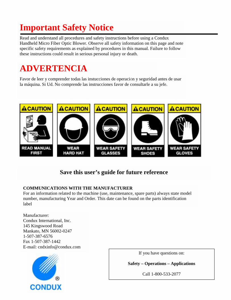
Important Safety Notice Read and understand all procedures and safety instructions before using a Condux Handheld Micro Fiber Optic Blower. Observe all safety information on this page and note specific safety requirements as explained by procedures in this manual. Failure to follow these instructions could result in serious personal injury or death.
ADVERTENCIA Favor de leer y comprender todas las instucciones de operaciÓn y seguridad antes de usar la máquina. Si Ud. No comprende las instrucciones favor de consultarle a su jefe.
Save this user’s guide for future reference
COMMUNICATIONS WITH THE MANUFACTURER For an information related to the machine (use, maintenance, spare parts) always state model number, manufacturing Year and Order. This date can be found on the parts identification label
Manufacturer: Condux International, Inc. 145 Kingswood Road Mankato, MN 56002-0247 1-507-387-6576 Fax 1-507-387-1442 E-mail: [email protected]
If you have questions on:
Safety – Operations – Applications
Call 1-800-533-2077

3
1. General Information………………………………………… Page 4 2. Set up the Handheld Blower………………………………… Page 5 A. Pressure Test Conduit…………………………………… Page 5-8 3. Prepare Conduits for Cable…………………………………. Page 9&10 4. Prepare Cable/Micro Cable…………………………………. Page 11 A. Prepare Traditional Fiber Cable………………………… Page 11&12 B. Prepare Micro Fiber Cable……………………………… Page 12&13 5. Handheld Blower Operating Instructions…………………… Page 14&15 6. Handheld Blower Assembly………………………………… Page 16 Cable Pack & Duct Pack Selection Charts……………………… Page 17 Micro Duct Selection Chart & Micro Carrier Chart…………….. Page 18 Recommended Cable Lubricants………………………………… Page 19 Warranty Information……………………………………………. Page 20
Table of Contents

4
General Information General Product Use
a. Only qualified operators should use this product. The operator should only be the person who received qualified training from the product owning company or trained by the manufacturer.
b. Product must only be used for the work it was designed for. c. Product is not to be used with unauthorized personnel on the job site d. Should there be any doubt concerning use, functioning, maintenance or
anything else, please contact the factory or factory representative. Operator Qualifications
a. Operator must know the required safety directives to run the product that are pertinent to the country where it is being used.
b. Operator in charge of the product and installation project must be appropriately dressed, avoiding large clothes, hanging jewelry or whatever might become entangled in the moving parts
c. Operator must also wear the necessary protective equipment such as gloves, boots, helmet, etc.
d. Operator must carefully follow all advisements contained in the instruction manual or on the machine
e. Operator must have work area kept clean of obstacles that might inhibit a safe working area.
Maintenance Qualification
a. Periodically inspect product for wear and tear. b. Authorized and trained personnel must do all maintenance operations.
Trained personnel are defined as people who have received qualified training from the using company or from the manufacturer

5
Set Up the Handheld Blower Pressure Test Conduit: The conduit system must be able to withstand a maximum pressure of 175 psi, and be free of leaks. Conduit may be tested for pressure using the Handheld cable blower, follow the steps below.
1. Loosen the speedball handle by turning it counter clockwise (Figure 1) until you are able to remove it from the bracket (Figure 2).
2. Select the correct Condux and Cable Components according to the conduit and cable size. Refer to the Conduit and Cable Pack selection charts (Table 1, 2, 3 & 4 on pages 17 & 18).
3. Choose the correct Conduit Seal and install both halves securely.
Use the provided 2.5 mm hex wrench (Figure 3).
4. Choose the correct Conduit Clamp and install both halves (same color as the conduit seal). Used the provided 2.5 mm hex wrench (Figure 4).
Figure 1 Loosen speedball handle Figure 2 Remove speedball handle from bracket
Figure 3 Install conduit seal Figure 4 Install conduit clamp

6
5. Choose the correct Venturi to fit the cable being installed. Do not install at this time!
6. Place the Seal Disk in Venturi Slot (See Figure 5).
7. Place conduit in the Conduit Seal and Conduit Clamp. Note placement up to
ridge on Conduit Seal (See Figure 6).
8. Close Handheld Blower and secure (See Figure 7). Tighten speedball handle securely, but do not over tighten.
9. Plug receiving end of Conduit with a propFigure 8).
Figure 5 Insert seal disk
Figure 7 Close and tig
Figure 8 Inse
Figure 6 Insert duct
erly sized Conduit Pulling Eye (See hten handle
rt innerduct eye
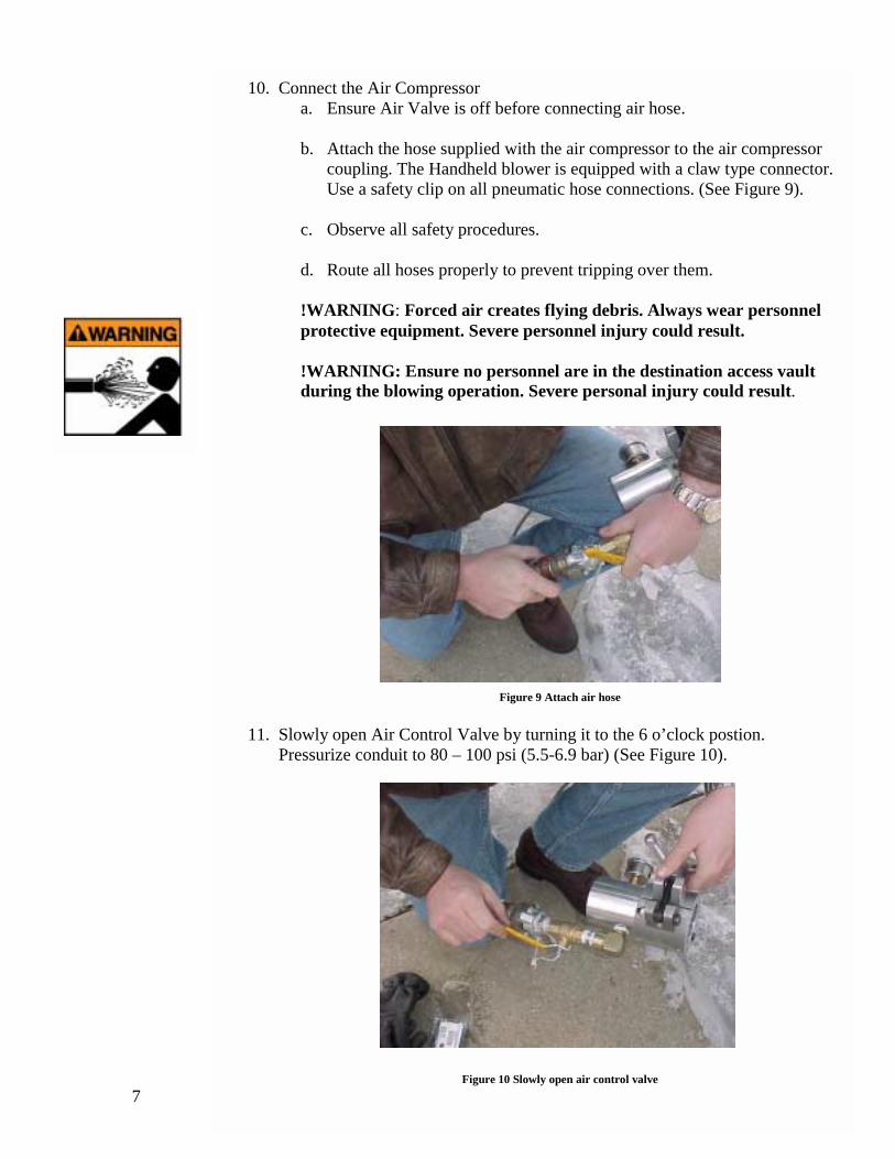
10. Connect the Air Compressor a. Ensure Air Valve is off before connecting air hose.
b. Attach the hose supplied with the air compressor to the air compressor
coupling. The Handheld blower is equipped with a claw type connector. Use a safety clip on all pneumatic hose connections. (See Figure 9).
c. Observe all safety procedures.
d. Route all hoses properly to prevent tripping over them.
!WARNING: Forced air creates flying debris. Always wear personnel protective equipment. Severe personnel injury could result.
7
!WARNING: Ensure no personnel are in the destination access vault during the blowing operation. Severe personal injury could result.
11. Slowly open
Pressurize co
Air Control Valve by turning it to the 6 o’clock postion. nduit to 80 – 100 psi (5.5-6.9 bar) (See Figure 10).
Figure 9 Attach air hose
Figure 10 Slowly open air control valve

8
12. Prove conduit integrity. a. Close Air Control Valve by turning it to the 3 o’clock position
(See Figure 11)
b. Conduit must not lose more than 20 psi (1.38 bar) over a 2-minute period.
c. After 2 minutes, turn air compressor valve off leaving the
blower pressure valve on until the air pressure gauge reads zero.
d. If conduit fails to hold required pressure, check entire conduit run for leaks and repair them.
e. Repeat the pressure test until all leaks are found and repaired.
!WARNING: Handheld Blower contains compressed air when blower is operated. Opening the Blower while under pressure may cause serious personnel injury. Ensure blower is depressurized before opening the Handheld blower and removing the conduit pulling eye.
13. Decompress the Handheld Blower by turning the air compressor air
valve off leaving the blower pressure valve on until the air pressure gauge reads Zero. Disconnect air hose from handheld blower pressure valve.
Figure 11 Close air control valve

9
Prepare Conduit for Cable 1. Remove Conduit Pulling Eye from receiving end of Conduit.
2. Open Handheld Blower (See Figure 12)
3. Pour recommended (silicon-based) lubricant into Conduit opening before Foam Carrier ¼ of the total recommend amount (See Figure 13) foam carriers are not provided with the Handheld blower. (See Page 19 for recommend amount of lubrication).
4. Insert foam into conduit (See Figure 14).
5. Insert Seal Disk in venturi slot if not already in place. (Figure 15).
Figure 12 Open handheld blower
Figure 13 Add lubricant
Figure 14 Insert foam carrier
Figure 15 Insert seal disk

10
6. Close the Handheld Blower and secure (See Figure 16) Tighten speedball handle securely, but do not over tighten.
7. Prove Conduit integrity and spread lubricant through Conduit.
a. Re-connect the air hose to the Handheld Blower and attach all
safety clips. b. Open the air compressor air control valve.
c. Slowly open Air Control Valve by turning to the 6 o’clock
position. (See Figure 17)
d. Blow foam through conduit to spread lubricant and check for blockage. Follow all safety precautions.
e. After the foam exits, close Air Control Valve by turning it to the 3
o’clock position.
Note: Foam must exit in a reasonable time, allow approximately 10 seconds per 1,000 feet (300 m) or conduit may be contaminated or blocked.
8. Ensure Handheld Blower is decompressor, decompress the aithe handheld blower.
9. Remove Seal Disk and install V
2.5 mm hex wrench.
Note: The venturi with the groove goes into the bottom and gets screwed into place while the top half has the protrusion and sets into the groove.
Figure 16 close and tighten handle
pressurized. Shut off the air from the r in the hose and disconnect the hoses from
entrui (See Figure 18). Use the provided
Figure 17 Slowly open the air control valve
Figure 18 Insert ventrui

11
Prepare Cable/Microcable The Handheld Blower can be used to install traditional fiber cable or Micro Fiber Cable. Follow the steps below for the type of cable you will be installing. Prepare Traditional Fiber Cable:
1. Choose the correct Cable Grip and install on the fiber optic cable (See Figure 19).
2. Install 5/8” (16 mm) Swivel on Cable Grip using a 3/32” hex wrench.
Grip must be firmly secured to cable (See Figure 20). The eye on the grip can be compressed to fit smaller diameter conduits. The eye of a new grip can be taped with electrical tape in order to make it narrower and travel more easily through the conduit.
3. C
4. Aa
5. P
6. A
hose the correct Carrier and inst
dd lubricant to Conduit before Cmount.
ush Cable Assembly, including e
dd the rest of the lubricant to the
Figure 19 Installing Cable Grip
Figure 21 Inst
all on Swivel (See Figure 21)
arrier: ¼ of the recommended
ntire cable grip, into conduit.
Conduit behind the Cable Assembly.
Figure 20 Installing Swivel
all carrier

12
7. Choose the correct Cable Seals and install on cable. Grooved side of Cable Seal faces the conduit. Place Cable Seals into the Venturi, split side down
8. Close the handheld blower and secure, Tighten speedball handle
securely, but do not over tighten. Prepare Micro Fiber Cable The carriers are designed to attach to the central strength member (CSM) of the cable. The seals are sized to accommodate the proper ID duct size for maximization of blowing distances and create and air tight seal in the duct. A caliper has been included into the, Micro Duct Carrier Kit (not included), for proper sizing of the correct Push Retainers. A bottle of adhesive is added to reinforce the attachment of the push retainers.
1. Strip the fiber cable down to the CSM, approximately 5/8” (16 mm) form the end (See Figure 22).
2. Select proper carrier seals for the duct inside diameter (ID) (See Table 1)
Duct ID (mm) Condux Carrier Seal P/N 8 08764118 10 08764128 12 08764138 14 08764148
3. Select the proper Push Retainers based on the CSM diameter
measurement taken with the included calipers (See Table 2). Central Strength Member (CSM)
Dia. (mm) Condux Push Retainer P/N
1.5 02289350 2.0 02289351 2.5 02289352 3.0 02289353
Figure 22: Strip of the CSM to length of approximately 5/8” (16 mm)

13
4. Slide two (2) Carrier Seals onto the CSM followed by two (2) Push Retainers. The seals should be relatively loose on the fiber but retained on the CSM with the Push Retainers.
Note: Notice the direction of how the Push Retainers need to be assembled to the fiber. The cone portion of the retainer faces the end of the CSM. They should fit very tight onto the fiber. 5. Apply a tug on the Carrier Seals toward the end of the fiber to ensure the
Push Retainers do not come off.
6. Apply adhesive to the front of the retainers where they interface with the fiber. Allow for the adhesive to setup (See Figure 23)
7. Check that Microcable slides smoothly in the Microduct.
8. The Microcable CSM may be trimmed back and/or wrapped with tape to create a “bullet” configuration to prevent any jamming in the duct.
9. Push the Cable Assembly, into the conduit.
10. Add the rest of the lubricant to Conduit behind the Cable Assembly.
11. Choose the correct cable seals and install on cable. Grooved side of
Cable Seal faces conduit. Place Cable Seals into Ventrui, Split side down
12. Close handheld blower and secure, tighten speedball handle securely, but do not over tighten.
Figure 23: Assembly of Carriers onto the CSM of Micro Fiber Optic Cable.
14
Handheld Blower Operating Instructions
1. Station an observer with a 2-way communication device, at the far end of the Conduit, where the cable carrier will exit.
2. Re-connect hose from air compressor and attach all safety clips. Start
the air compressor. Refer to respective manufacturers operating instructions for these units.
3. Slowly open the Air Control Valve to allow airflow to the Handheld
Blower by turning the flow control valve hand to the 6 o’clock position.
4. Maintain control of the cable reel to ensure smooth, stable flow.
Failure to do so may cause cable to unwind to quickly. Continue to control cable speed with the flow control knob.
!WARNING: Never wrap line around your hand, arm, foot or leg. Severe personal injury or death could result from entanglement. !CAUTION: Always wear protective equipment: hard hat, safety glasses, safety shoes and work gloves. 5. Turn off the Air Control Valve immediately when the observer
indicates the cable carrier has exited the Conduit (air pressure will decrease sharply).
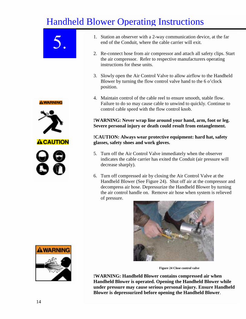
6. Turn off compressed air by closing the Air Control Valve at the
Handheld Blower (See Figure 24). Shut off air at the compressor and decompress air hose. Depressurize the Handheld Blower by turning the air control handle on. Remove air hose when system is relieved of pressure.
!WARNING: HanHandheld Blower under pressure maBlower is depressu
dheld Blower contains compressed air when is operated. Opening the Handheld Blower while y cause serious personal injury. Ensure Handheld rized before opening the Handheld Blower.
Figure 24 Close control valve

15
7. Open Handheld Blower and remove cable seals (See Figure 25).
8. Pull Conduit and Cable out of the Handheld Blower
Figure 25 Open Handheld Blower and Remove Cable and Duct
16
Ite
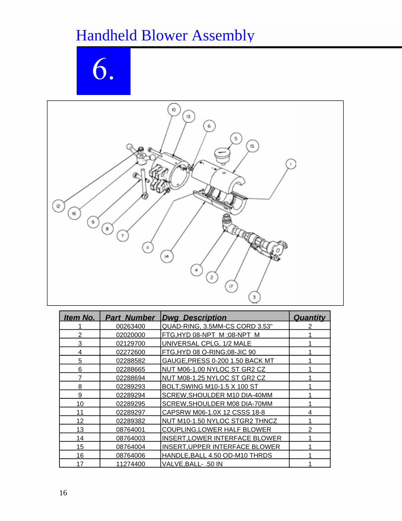
Handheld Blower Assemblym No. Part_Number Dwg_Description Quantity1 00263400 QUAD-RING, 3.5MM-CS CORD 3.53" 22 02020000 FTG,HYD 08-NPT_M ;08-NPT_M 13 02129700 UNIVERSAL CPLG, 1/2 MALE 14 02272600 FTG,HYD 08 O-RING;08-JIC 90 15 02288582 GAUGE,PRESS 0-200 1.50 BACK MT 16 02288665 NUT M06-1.00 NYLOC ST GR2 CZ 17 02288694 NUT M08-1.25 NYLOC ST GR2 CZ 18 02289293 BOLT,SWING M10-1.5 X 100 ST 19 02289294 SCREW,SHOULDER M10 DIA-40MM 110 02289295 SCREW,SHOULDER M08 DIA-70MM 111 02289297 CAPSRW M06-1.0X 12 CSSS 18-8 412 02289382 NUT M10-1.50 NYLOC STGR2 THNCZ 113 08764001 COUPLING,LOWER HALF BLOWER 214 08764003 INSERT,LOWER INTERFACE BLOWER 115 08764004 INSERT,UPPER INTERFACE BLOWER 116 08764006 HANDLE,BALL 4.50 OD-M10 THRDS 117 11274400 VALVE,BALL- .50 IN 1

Table 1 Conduit Packs
D u ct P ack D u ct C lam p D u ct S ea l C arrier F o am C arrier C ab le G ripD u ct S ize P /N D u ct O D P/N D u ct O D P /N D u ct ID P /N C arrier O D P /N D u ct O D P /N
1" 08780386 1.315 08780369 1.315 08780307 1.121 08761811 1.25 08761439 1.00-1 .24 08643137S D R 11 /13 .5 Pack #1 (33 .4 ) B lue (33 .4 ) B lue (28.5 ) (31 .8 ) (25 .4 -31 .5 ) 033-03-013
1 .25" 08780392 1.660 08780375 1.660 08780051 1.414 08761817 1.50 08761440 1.50-1 .99 08643149S D R 11 /13 .5 Pack #2 (42 .2 ) G reen (42 .2 ) G reen (35.9 ) (38 .1 ) (38 .1 -50 .5 ) 033-03-016
1 .5" 08780397 1.900 08780404 1.900 08780398 1.618 08761819 1.75 08761441 1.50-1 .99 08643149S D R 11 /13 .5 Pack #3 (48 .3 ) R ed (48 .3 ) R ed (41.1 ) (44 .5 ) (38 .1 -50 .5 ) 033-03-016
25 m m 08780240 0.984 08780099 0.984 08780134 0.787 08780230 1.25 08761439 1.00-1 .24 08643137(25 .0 ) O range (25 .0 ) O range (20.0 ) (31 .8 ) (25 .4 -31 .5 ) 033-03-013
32 m m 08780385 1.260 08780368 1.260 08780306 1.063 08761810 1.25 08761439 1.25-1 .49 08643143(32 .0 ) G o ld (32 .0 ) G o ld (27.0 ) (31 .8 ) (31 .8 -37 .8 ) 033-03-015
36 m m 08780387 1.417 08780370 1.417 08780308 1.181 (30 .0 ) 08761812 1.25 08761439 1.25-1 .49 08643143(36 .0 ) R ed (36 .0 ) R ed 1.220 (31 .0 ) 08761813 (31 .8 ) (31 .8 -37 .8 ) 033-03-015
37 m m 08780388 1.457 08780371 1.457 08780309 1.220 08761813 1.25 08761439 1.25-1 .49 08643143(37 .0 ) B lue-G ray (37 .0 ) B lue-G ray (31.0 ) (31 .8 ) (31 .8 -37 .8 ) 033-03-015
1 .25" T R U E 08780389 1.500 08780372 1.500 08780333 1.250 08761814 1.50 08761440 1.25-1 .49 08643143(38 .1 ) C lear A lum . (38 .1 ) C lear A lum . (31.7 ) (38 .1 ) (31 .8 -37 .8 ) 033-03-015
40 m m 08780390 1.575 08780373 1.575 08780334 1.299 08761815 1.50 08761440 1.50-1 .99 08643149(40 .0 ) B lack (40 .0 ) B lack (33.0 ) (38 .1 ) (38 .1 -50 .5 ) 033-03-016
42 m m 08780391 1.653 08780374 1.653 08780335 1.378 08761816 1.50 08761440 1.50-1 .99 08643149(42 .0 ) B lue-G ray (42 .0 ) B lue-G ray (35.0 ) (38 .1 ) (38 .1 -50 .5 ) 033-03-016
44 m m 08780545 1.732 08780546 1.732 08780547 1.496 08761786 1.50 08761440 1.50-1 .99 08643149(44 .0 ) G o ld (44 .0 ) G o ld (38.0 ) (38 .1 ) (38 .1 -50 .5 ) 033-03-016
50 m m 08780575 1.969 08780435 1.969 08780431 1.606 08761818 2.00 08761442 1.50-1 .99 08643149(50 .0 ) B lue (50 .0 ) B lue (40.0 ) (50 .8 ) (38 .1 -50 .5 ) 033-03-016


C a b le P a c k V e n t u r i C a b le S e a l C a b le G r ip
C a b le O D P /N C a b le O D P /N C a b le O D P /N C a b le O D P /N0 .2 3 - 0 .2 8 0 8 7 8 0 4 0 6
0 .2 3 - 0 .3 4 0 8 7 8 0 3 9 3 0 .2 3 - 0 .3 4 0 8 7 8 0 2 8 1 ( 5 .8 - 7 .2 ) 0 .2 1 - 0 .3 5 0 8 6 4 3 7 5 4( 5 .8 - 8 .8 ) Pa c k # 1 ( 5 .8 - 8 .8 ) Pu r p le 0 .2 9 - 0 .3 4 0 8 7 8 0 4 0 7 ( 5 .3 - 8 .9 ) 0 3 3 - 2 9 - 1 1 9 4
( 7 .3 - 8 .8 )0 .3 5 - 0 .4 2 0 8 7 6 1 4 2 4
0 .3 5 - 0 .4 8 0 8 7 8 0 2 8 2 ( 8 .9 - 1 0 .7 ) 0 .3 2 - 0 .4 8 0 8 6 4 3 7 5 5( 8 .9 - 1 2 .2 ) B lu e 0 .4 3 - 0 .4 8 0 8 7 6 1 4 2 5 ( 8 .1 - 1 2 .2 ) 0 3 3 - 2 9 - 1 1 9 5
0 .3 5 - 0 .6 0 0 8 7 8 0 3 9 4 ( 1 0 .8 - 1 2 .2 )( 8 .9 - 1 5 .2 ) Pa c k # 2 0 .4 9 - 0 .5 5 0 8 7 6 1 4 2 6
0 .4 9 - 0 .6 0 0 8 7 8 0 2 8 3 ( 1 2 .3 - 1 4 .0 ) 0 .4 2 - 0 .6 1 0 8 6 4 3 7 5 6( 1 2 .3 - 1 5 .2 ) G r e e n 0 .5 6 - 0 .6 0 0 8 7 6 1 4 2 7 ( 1 0 .7 - 1 5 .5 ) 0 3 3 - 2 9 - 1 1 9 6
( 1 4 .1 - 1 5 .2 )0 .6 1 - 0 .6 7 0 8 7 6 1 4 2 8
0 .6 1 - 0 .7 3 0 8 7 8 0 2 8 4 ( 1 5 .3 - 1 7 .0 ) 0 .5 3 - 0 .7 4 0 8 6 4 3 7 5 7( 1 5 .3 - 1 8 .5 ) R e d 0 .6 8 - 0 .7 3 0 8 7 6 1 4 2 9 ( 1 3 .5 - 1 8 .8 ) 0 3 3 - 2 9 - 1 1 9 7
0 .6 1 - 0 .8 5 0 8 7 8 0 3 9 5 ( 1 7 .1 - 1 8 .5 )( 1 5 .3 - 2 1 .6 ) Pa c k # 3 0 .7 4 - 0 .7 9 0 8 7 6 1 4 3 0
0 .7 4 - 0 .8 5 0 8 7 8 0 2 8 5 ( 1 8 .6 - 2 0 .1 ) 0 .6 4 - 0 .8 7 0 8 6 4 3 7 5 8( 1 8 .6 - 2 1 .6 ) G o ld 0 .8 0 - 0 .8 5 0 8 7 6 1 4 3 1 ( 1 6 .3 - 2 2 .1 ) 0 3 3 - 2 9 - 1 1 9 8
( 2 0 .2 - 2 1 .6 )0 .8 6 - 0 .9 2 0 8 7 6 1 4 3 2
0 .8 6 - 0 .9 7 0 8 7 8 0 2 8 6 ( 2 1 .7 - 2 3 .4 ) 0 .7 5 - 1 .0 0 0 8 6 4 3 7 5 9( 2 1 .7 - 2 4 .6 ) C le a r A lu m . 0 .9 3 - 0 .9 7 0 8 7 6 1 4 3 3 ( 1 9 .1 - 2 5 .4 ) 0 3 3 - 2 9 - 1 1 9 9
0 .8 6 - 1 .1 3 0 8 7 8 0 3 9 6 ( 2 3 .5 - 2 4 .6 )( 2 1 .7 - 2 8 .7 ) Pa c k # 4 0 .9 8 - 1 .0 4 0 8 7 6 1 4 3 4
0 .9 8 - 1 .1 3 0 8 7 8 0 4 4 6 ( 2 4 .7 - 2 6 .4 ) 1 .0 0 - 1 .2 4 0 8 6 4 3 1 3 7( 2 4 .7 - 2 8 .7 ) B la c k 1 . .0 5 - 1 .1 3 0 8 7 6 1 4 3 5 ( 2 5 .4 - 3 1 .5 ) 0 3 3 - 0 3 - 0 1 3
( 2 6 .5 - 2 8 .7 )
Table 2. Cable Packs
MICRO DUCT PACKS Innerduct EyeDuct Size OD (MM) Part Number Duct Clamp Duct Seal ID Range P/N
10 08764140 08764142 0876414312 08764110 08764112 08764113 10-12 mm 0891354514 08764120 08764122 08764123 10-12 mm 0891354516 08764130 08764132 08764133 10-12 mm 08913545
Table 3. Micro Duct Packs
Carrier Kit - Micro Fiber (P/N 08764090)
Kit Includes:
P/N Description Qty02289350 RETAINER,PUSHON QCKLCK 1.5MM 2002289351 RETAINER,PUSHON QCKLCK 2.0MM 2002289352 RETAINER,PUSHON QCKLCK 2.5MM 2002289353 RETAINER,PUSHON QCKLCK 3.0MM 2008764118 DISC,CARRIER - 08MM ID DUCT 1008764128 DISC,CARRIER - 10MM ID DUCT 1008764138 DISC,CARRIER - 12MM ID DUCT 1008764148 DISC,CARRIER - 14MM ID DUCT 1002284200 ADHESIVE,LOCTITE 38004 3GM TBE 102288875 CALIPER,CABLE DIAMETER 1

20
Recommended Blowing Lubricants Polywater® Prelube 2000™ Polywater Prelube 5000™ Polywater® Prelube 5000™ is more concentrated than the Prelube 2000™. It is intended for blowing microcable into small diameter microtubes. The improved chemistry allows this product to spread further and lower friction low coasting levels. The lower viscosity allows practical application into the microtubes.
Specially formulated for use with fiber optic cable blowing systems, Polywater® Prelube 2000™ has been field proven with the Deluxe LW Blower. This lubricant is a special lubricant used to prelubricate the conduit system before installing the cable. Prelube 2000™ is compatible with all types of cable jackets andconduit types.
StdPkg
Part Number Description Qty08230600 1 Quart (.9 liter) Squeeze Bottle 12/case08230601 1 Gallon (3.8 liter) Jug 4/case08230900 1 Quart (.9 liter) Squeeze Bottle Winter Grade 12/case08230901 1 Gallon (3.8 liter) Jug Winter Grade 4/case
Polywater® Prelube 2000™ recommended usage quantity
Lubricant QuantityDuct Size Per 1,000 Feet Per Kilometer
1 inch 3 fl. oz. 300 ml1.25 inch 4 fl. oz. 400 ml1.5 inch 5 fl. oz. 500 ml2 inch 6 fl. oz. 600 ml
Part Number Description Std Pkg Qty
Lubricant QuantityTube Size (OD/ID) Volume Required Fill Length of Microtube
14/12 0.30 fl. Oz. (9 ml) 3 in. (8 cm)12/10 0.25 fl. Oz. (7 ml) 4 in. (10 cm)10/8 0.20 fl. Oz (6 ml) 5 in. (12 cm)
Polywater® Prelube 5000™ recommended usage quantity
08230675 8 ft.oz squeeze bottle 6/case

21
WARRANTY INFORMATION
Condux International, Incorporated extends the following warranty to the original purchaser of these goods for use, subject to the qualifications indicated: Condux International, Incorporated warrants to the original purchaser for use that the goods or any component thereof manufactured by Condux International will be free from defects in workmanship for a period of 1 year form the date of purchase, provided such goods are installed, maintained, and used in accordance with Condux’s written instructions. Components not manufactured by Condux International but used within the assembly provided by Condux Internationalare subject to the warranty period as specified by the individual manufacturer of said component, provided such goods are installed, maintained, and used in accordance with Condux’s and the original manufactures written instructions. Condux’s sole liability and the purchaser’s sole remedy for a failure of goods under this limited warranty, and for any and all claims arising out of the purchase and use of goods, shall be limited to the repair or replacement of the goods that do not conform to this warranty. To obtain repair of replacement service under the limited warranty, the purchaser must contact the factory for a Return Material Authorization (RMA), Once obtained, send the RMA along with the defective part or goods, transportation prepaid, to: Condux International, Inc. 145 Kingswood Road Mankato, MN 56001 USA THERE ARE NO EXPRESS WARRANTIES COVERING THESE GOODS OTHER THAN AS SET FORTH ABOVE. THE IMPLIED WARRANTIES OR MERCHANTABILITY AND FITNESS FOR PARTICULAR PURPOSE ARE LIMITED IN DURATION TO ONE YEAR FROM DATE OF PURCHASE
CONDUX ASSSUMES NO LIABILITY IN CONNECTION WITH THE INSTALLATION OR USE OF THIS PRODUCT, EXCEPT AS STATED IN THIS LIMITED WARRANTY, CONDUX WILL IN NO EVENT BE LIABLE FOR INCIDENTAL OR CONSEQUENTIAL DAMAGES
©Copyright 2005, Condux International, Inc. Printed in USA Literature Part Number 08764010 Revision Number 1.0


