44
Processes OM-947 212 149A February 2003 Handler 125 / 125 MIG And H-9 Gun Arc Welding Power Source And Wire Feeder Description MIG (GMAW) Welding (Optional) Flux Cored (FCAW) Welding

Processes
OM-947 212 149A
February 2003
Handler 125 / 125 MIG
And H-9 Gun
Arc Welding Power Source AndWire Feeder
Description
MIG (GMAW) Welding (Optional)
Flux Cored (FCAW) Welding

Hobart Welders manufactures a full lineof welders and welding related equipment.For information on other quality Hobart products, contact your local Hobartdistributor to receive the latest full line catalog or individual catalog sheets.To locate your nearest distributor or service agency call 1-877-Hobart1.
Thank you and congratulations on choosing Hobart. Now you can get thejob done and get it done right. We know you don’t have time to do it anyother way.
This Owner’s Manual is designed to help you get the most out of yourHobart products. Please take time to read the Safety precautions. Theywill help you protect yourself against potential hazards on the worksite.
We’ve made installation and operation quickand easy. With Hobart you can count on yearsof reliable service with proper maintenance.And if for some reason the unit needs repair,there’s a Troubleshooting section that will helpyou figure out what the problem is. The partslist will then help you to decide the exact partyou may need to fix the problem. Warranty andservice information for your particular modelare also provided.
Hobart is registered to theISO 9001:2000 QualitySystem Standard.
Working as hard as youdo – every power sourcefrom Hobart is backed bythe best warranty in thebusiness.
From Hobart to You
Hobart offers a TechnicalManual which providesmore detailed service andparts information for yourunit. To obtain a TechnicalManual, contact your localdistributor. Your distributorcan also supply you withWelding Process Manualssuch as SMAW, GTAW,GMAW, and GMAW-P.

TABLE OF CONTENTS
SECTION 1 – SAFETY PRECAUTIONS - READ BEFORE USING 1. . . . . . . . . . . . . . . . . . . . . . . . . . . . 1-1. Symbol Usage 1. . . . . . . . . . . . . . . . . . . . . . . . . . . . . . . . . . . . . . . . . . . . . . . . . . . . . . . . . . . . . . . . 1-2. Arc Welding Hazards 1. . . . . . . . . . . . . . . . . . . . . . . . . . . . . . . . . . . . . . . . . . . . . . . . . . . . . . . . . . 1-3. Additional Symbols For Installation, Operation, And Maintenance 3. . . . . . . . . . . . . . . . . . . . .
1-4. Principal Safety Standards 3. . . . . . . . . . . . . . . . . . . . . . . . . . . . . . . . . . . . . . . . . . . . . . . . . . . . . 1-5. EMF Information 4. . . . . . . . . . . . . . . . . . . . . . . . . . . . . . . . . . . . . . . . . . . . . . . . . . . . . . . . . . . . . .
SECTION 1 – CONSIGNES DE SECURITE – LIRE AVANT UTILISATION 5. . . . . . . . . . . . . . . . . . . . . 1-1. Signification des symboles 5. . . . . . . . . . . . . . . . . . . . . . . . . . . . . . . . . . . . . . . . . . . . . . . . . . . . . 1-2. Dangers relatifs au soudage à l’arc 5. . . . . . . . . . . . . . . . . . . . . . . . . . . . . . . . . . . . . . . . . . . . . .
1-3. Dangers supplémentaires en relation avec l’installation, le fonctionnementet la maintenance 7. . . . . . . . . . . . . . . . . . . . . . . . . . . . . . . . . . . . . . . . . . . . . . . . . . . . . . . . . . . . .
1-4. Principales normes de sécurité 8. . . . . . . . . . . . . . . . . . . . . . . . . . . . . . . . . . . . . . . . . . . . . . . . . . 1-5. Information sur les champs électromagnétiques 8. . . . . . . . . . . . . . . . . . . . . . . . . . . . . . . . . . . .
SECTION 2 – SPECIFICATIONS 9. . . . . . . . . . . . . . . . . . . . . . . . . . . . . . . . . . . . . . . . . . . . . . . . . . . . . . . . . 2-1. Specifications 9. . . . . . . . . . . . . . . . . . . . . . . . . . . . . . . . . . . . . . . . . . . . . . . . . . . . . . . . . . . . . . . . 2-2. Duty Cycle And Overheating 9. . . . . . . . . . . . . . . . . . . . . . . . . . . . . . . . . . . . . . . . . . . . . . . . . . . . 2-3. Volt-Ampere Curves 10. . . . . . . . . . . . . . . . . . . . . . . . . . . . . . . . . . . . . . . . . . . . . . . . . . . . . . . . . . .
SECTION 3 – INSTALLATION 10. . . . . . . . . . . . . . . . . . . . . . . . . . . . . . . . . . . . . . . . . . . . . . . . . . . . . . . . . . . 3-1. Installing Work Clamp 10. . . . . . . . . . . . . . . . . . . . . . . . . . . . . . . . . . . . . . . . . . . . . . . . . . . . . . . . . .
3-2. Process/Polarity Table 10. . . . . . . . . . . . . . . . . . . . . . . . . . . . . . . . . . . . . . . . . . . . . . . . . . . . . . . . . 3-3. Changing Polarity 11. . . . . . . . . . . . . . . . . . . . . . . . . . . . . . . . . . . . . . . . . . . . . . . . . . . . . . . . . . . . . 3-4. Installing Gas Supply 11. . . . . . . . . . . . . . . . . . . . . . . . . . . . . . . . . . . . . . . . . . . . . . . . . . . . . . . . . . 3-5. Installing Wire Spool And Adjusting Hub Tension 12. . . . . . . . . . . . . . . . . . . . . . . . . . . . . . . . . . .
3-6. Selecting A Location And Connecting Input Power For 115 VAC Model 13. . . . . . . . . . . . . . . . . 3-7. Threading Welding Wire 14. . . . . . . . . . . . . . . . . . . . . . . . . . . . . . . . . . . . . . . . . . . . . . . . . . . . . . . .
SECTION 4 – OPERATION 15. . . . . . . . . . . . . . . . . . . . . . . . . . . . . . . . . . . . . . . . . . . . . . . . . . . . . . . . . . . . . 4-1. Controls 15. . . . . . . . . . . . . . . . . . . . . . . . . . . . . . . . . . . . . . . . . . . . . . . . . . . . . . . . . . . . . . . . . . . . . 4-2. Weld Parameter Chart 16. . . . . . . . . . . . . . . . . . . . . . . . . . . . . . . . . . . . . . . . . . . . . . . . . . . . . . . . .
SECTION 5 – MAINTENANCE &TROUBLESHOOTING 18. . . . . . . . . . . . . . . . . . . . . . . . . . . . . . . . . . . . . 5-1. Routine Maintenance 18. . . . . . . . . . . . . . . . . . . . . . . . . . . . . . . . . . . . . . . . . . . . . . . . . . . . . . . . . . 5-2. Overload Protection 18. . . . . . . . . . . . . . . . . . . . . . . . . . . . . . . . . . . . . . . . . . . . . . . . . . . . . . . . . . . 5-3. Drive Motor Protection 18. . . . . . . . . . . . . . . . . . . . . . . . . . . . . . . . . . . . . . . . . . . . . . . . . . . . . . . . . 5-4. Changing Drive Roll Or Wire Inlet Guide 19. . . . . . . . . . . . . . . . . . . . . . . . . . . . . . . . . . . . . . . . . .
5-5. Replacing Gun Contact Tip 20. . . . . . . . . . . . . . . . . . . . . . . . . . . . . . . . . . . . . . . . . . . . . . . . . . . . . 5-6. Cleaning Or Replacing Gun Liner 21. . . . . . . . . . . . . . . . . . . . . . . . . . . . . . . . . . . . . . . . . . . . . . . . 5-7. Replacing Switch And/Or Head Tube 23. . . . . . . . . . . . . . . . . . . . . . . . . . . . . . . . . . . . . . . . . . . . . 5-8. Troubleshooting Table 24. . . . . . . . . . . . . . . . . . . . . . . . . . . . . . . . . . . . . . . . . . . . . . . . . . . . . . . . .
SECTION 6 – ELECTRICAL DIAGRAM 25. . . . . . . . . . . . . . . . . . . . . . . . . . . . . . . . . . . . . . . . . . . . . . . . . . .
(Continued)OM-947
WARNINGThis product, when usedfor welding or cutting,produces fumes orgases which containchemicals known to theState of California tocause birth defects and,in some cases, cancer.(California Health &Safety Code Section25249.5 et seq.)
The following terms areused interchangeablythroughout this manual:MIG=GMAW

TABLE OF CONTENTS
SECTION 7 – WIRE WELDING GUIDELINES 26. . . . . . . . . . . . . . . . . . . . . . . . . . . . . . . . . . . . . . . . . . . . . . 7-1. Typical FCAW Process Connections 26. . . . . . . . . . . . . . . . . . . . . . . . . . . . . . . . . . . . . . . . . . . . . 7-2. Typical MIG Process Connections 26. . . . . . . . . . . . . . . . . . . . . . . . . . . . . . . . . . . . . . . . . . . . . . . 7-3. Typical Control Settings 27. . . . . . . . . . . . . . . . . . . . . . . . . . . . . . . . . . . . . . . . . . . . . . . . . . . . . . . .
7-4. Holding And Positioning Welding Gun 28. . . . . . . . . . . . . . . . . . . . . . . . . . . . . . . . . . . . . . . . . . . . 7-5. Conditions That Affect Weld Bead Shape 29. . . . . . . . . . . . . . . . . . . . . . . . . . . . . . . . . . . . . . . . . 7-6. Gun Movement During Welding 30. . . . . . . . . . . . . . . . . . . . . . . . . . . . . . . . . . . . . . . . . . . . . . . . . 7-7. Poor Weld Bead Characteristics 30. . . . . . . . . . . . . . . . . . . . . . . . . . . . . . . . . . . . . . . . . . . . . . . . . 7-8. Good Weld Bead Characteristics 30. . . . . . . . . . . . . . . . . . . . . . . . . . . . . . . . . . . . . . . . . . . . . . . .
7-9. Troubleshooting – Excessive Spatter 31. . . . . . . . . . . . . . . . . . . . . . . . . . . . . . . . . . . . . . . . . . . . . 7-10. Troubleshooting – Porosity 31. . . . . . . . . . . . . . . . . . . . . . . . . . . . . . . . . . . . . . . . . . . . . . . . . . . . . 7-11. Troubleshooting – Excessive Penetration 31. . . . . . . . . . . . . . . . . . . . . . . . . . . . . . . . . . . . . . . . . 7-12. Troubleshooting – Lack Of Penetration 32. . . . . . . . . . . . . . . . . . . . . . . . . . . . . . . . . . . . . . . . . . . 7-13. Troubleshooting – Incomplete Fusion 32. . . . . . . . . . . . . . . . . . . . . . . . . . . . . . . . . . . . . . . . . . . . .
7-14. Troubleshooting – Burn-Through 32. . . . . . . . . . . . . . . . . . . . . . . . . . . . . . . . . . . . . . . . . . . . . . . . . 7-15. Troubleshooting – Waviness Of Bead 33. . . . . . . . . . . . . . . . . . . . . . . . . . . . . . . . . . . . . . . . . . . . 7-16. Troubleshooting – Distortion 33. . . . . . . . . . . . . . . . . . . . . . . . . . . . . . . . . . . . . . . . . . . . . . . . . . . . 7-17. Troubleshooting Guide For Semiautomatic Welding Equipment 33. . . . . . . . . . . . . . . . . . . . . . .
SECTION 8 – PARTS LIST 34. . . . . . . . . . . . . . . . . . . . . . . . . . . . . . . . . . . . . . . . . . . . . . . . . . . . . . . . . . . . . .
OPTIONS AND ACCESSORIES
WARRANTY

OM-947 Page 1
SECTION 1 – SAFETY PRECAUTIONS - READ BEFORE USINGsom _nd_4/98
1-1. Symbol Usage
Means Warning! Watch Out! There are possible hazardswith this procedure! The possible hazards are shown inthe adjoining symbols.
� Marks a special safety message.
� Means “Note”; not safety related.
This group of symbols means Warning! Watch Out! possibleELECTRIC SHOCK, MOVING PARTS, and HOT PARTS hazards.Consult symbols and related instructions below for necessary actionsto avoid the hazards.
1-2. Arc Welding Hazards
� The symbols shown below are used throughout this manual tocall attention to and identify possible hazards. When you seethe symbol, watch out, and follow the related instructions toavoid the hazard. The safety information given below is onlya summary of the more complete safety information found inthe Safety Standards listed in Section 1-4. Read and follow allSafety Standards.
� Only qualified persons should install, operate, maintain, andrepair this unit.
� During operation, keep everybody, especially children, away.
ELECTRIC SHOCK can kill.
Touching live electrical parts can cause fatal shocksor severe burns. The electrode and work circuit iselectrically live whenever the output is on. The inputpower circuit and machine internal circuits are also
live when power is on. In semiautomatic or automatic wire welding, thewire, wire reel, drive roll housing, and all metal parts touching thewelding wire are electrically live. Incorrectly installed or improperlygrounded equipment is a hazard.
� Do not touch live electrical parts.
� Wear dry, hole-free insulating gloves and body protection.
� Insulate yourself from work and ground using dry insulating matsor covers big enough to prevent any physical contact with the workor ground.
� Do not use AC output in damp areas, if movement is confined, or ifthere is a danger of falling.
� Use AC output ONLY if required for the welding process.
� If AC output is required, use remote output control if present onunit.
� Disconnect input power or stop engine before installing orservicing this equipment. Lockout/tagout input power according toOSHA 29 CFR 1910.147 (see Safety Standards).
� Properly install and ground this equipment according to itsOwner’s Manual and national, state, and local codes.
� Always verify the supply ground – check and be sure that inputpower cord ground wire is properly connected to ground terminal indisconnect box or that cord plug is connected to a properlygrounded receptacle outlet.
� When making input connections, attach proper grounding conduc-tor first – double-check connections.
� Frequently inspect input power cord for damage or bare wiring –replace cord immediately if damaged – bare wiring can kill.
� Turn off all equipment when not in use.
� Do not use worn, damaged, undersized, or poorly spliced cables.
� Do not drape cables over your body.
� If earth grounding of the workpiece is required, ground it directlywith a separate cable.
� Do not touch electrode if you are in contact with the work, ground,or another electrode from a different machine.
� Use only well-maintained equipment. Repair or replace damagedparts at once. Maintain unit according to manual.
� Wear a safety harness if working above floor level.
� Keep all panels and covers securely in place.
� Clamp work cable with good metal-to-metal contact to workpieceor worktable as near the weld as practical.
� Insulate work clamp when not connected to workpiece to preventcontact with any metal object.
� Do not connect more than one electrode or work cable to anysingle weld output terminal.
SIGNIFICANT DC VOLTAGE exists after removal ofinput power on inverters.� Turn Off inverter, disconnect input power, and discharge input
capacitors according to instructions in Maintenance Sectionbefore touching any parts.
Welding produces fumes and gases. Breathingthese fumes and gases can be hazardous to yourhealth.
FUMES AND GASES can be hazardous.
� Keep your head out of the fumes. Do not breathe the fumes.
� If inside, ventilate the area and/or use exhaust at the arc to removewelding fumes and gases.
� If ventilation is poor, use an approved air-supplied respirator.
� Read the Material Safety Data Sheets (MSDSs) and themanufacturer’s instructions for metals, consumables, coatings,cleaners, and degreasers.
� Work in a confined space only if it is well ventilated, or whilewearing an air-supplied respirator. Always have a trained watch-person nearby. Welding fumes and gases can displace air andlower the oxygen level causing injury or death. Be sure the breath-ing air is safe.
� Do not weld in locations near degreasing, cleaning, or spraying op-erations. The heat and rays of the arc can react with vapors to formhighly toxic and irritating gases.
� Do not weld on coated metals, such as galvanized, lead, orcadmium plated steel, unless the coating is removed from the weldarea, the area is well ventilated, and if necessary, while wearing anair-supplied respirator. The coatings and any metals containingthese elements can give off toxic fumes if welded.

OM-947 Page 2
Arc rays from the welding process produce intensevisible and invisible (ultraviolet and infrared) raysthat can burn eyes and skin. Sparks fly off from theweld.
ARC RAYS can burn eyes and skin.
� Wear a welding helmet fitted with a proper shade of filter to protectyour face and eyes when welding or watching (see ANSI Z49.1and Z87.1 listed in Safety Standards).
� Wear approved safety glasses with side shields under yourhelmet.
� Use protective screens or barriers to protect others from flash andglare; warn others not to watch the arc.
� Wear protective clothing made from durable, flame-resistant mate-rial (leather and wool) and foot protection.
Welding on closed containers, such as tanks,drums, or pipes, can cause them to blow up. Sparkscan fly off from the welding arc. The flying sparks, hotworkpiece, and hot equipment can cause fires and
burns. Accidental contact of electrode to metal objects can causesparks, explosion, overheating, or fire. Check and be sure the area issafe before doing any welding.
WELDING can cause fire or explosion.
� Protect yourself and others from flying sparks and hot metal.
� Do not weld where flying sparks can strike flammable material.
� Remove all flammables within 35 ft (10.7 m) of the welding arc. Ifthis is not possible, tightly cover them with approved covers.
� Be alert that welding sparks and hot materials from welding caneasily go through small cracks and openings to adjacent areas.
� Watch for fire, and keep a fire extinguisher nearby.
� Be aware that welding on a ceiling, floor, bulkhead, or partition cancause fire on the hidden side.
� Do not weld on closed containers such as tanks, drums, or pipes,unless they are properly prepared according to AWS F4.1 (seeSafety Standards).
� Connect work cable to the work as close to the welding area aspractical to prevent welding current from traveling long, possiblyunknown paths and causing electric shock and fire hazards.
� Do not use welder to thaw frozen pipes.
� Remove stick electrode from holder or cut off welding wire atcontact tip when not in use.
� Wear oil-free protective garments such as leather gloves, heavyshirt, cuffless trousers, high shoes, and a cap.
� Remove any combustibles, such as a butane lighter or matches,from your person before doing any welding.
FLYING METAL can injure eyes.
� Welding, chipping, wire brushing, and grindingcause sparks and flying metal. As welds cool,they can throw off slag.
� Wear approved safety glasses with sideshields even under your welding helmet.
BUILDUP OF GAS can injure or kill.
� Shut off shielding gas supply when not in use.� Always ventilate confined spaces or use
approved air-supplied respirator.
HOT PARTS can cause severe burns.
� Do not touch hot parts bare handed.� Allow cooling period before working on gun or
torch.
MAGNETIC FIELDS can affect pacemakers.
� Pacemaker wearers keep away.� Wearers should consult their doctor before
going near arc welding, gouging, or spotwelding operations.
NOISE can damage hearing.
Noise from some processes or equipment candamage hearing.
� Wear approved ear protection if noise level ishigh.
Shielding gas cylinders contain gas under highpressure. If damaged, a cylinder can explode. Sincegas cylinders are normally part of the weldingprocess, be sure to treat them carefully.
CYLINDERS can explode if damaged.
� Protect compressed gas cylinders from excessive heat, mechani-cal shocks, slag, open flames, sparks, and arcs.
� Install cylinders in an upright position by securing to a stationarysupport or cylinder rack to prevent falling or tipping.
� Keep cylinders away from any welding or other electrical circuits.
� Never drape a welding torch over a gas cylinder.
� Never allow a welding electrode to touch any cylinder.
� Never weld on a pressurized cylinder – explosion will result.
� Use only correct shielding gas cylinders, regulators, hoses, and fit-tings designed for the specific application; maintain them andassociated parts in good condition.
� Turn face away from valve outlet when opening cylinder valve.
� Keep protective cap in place over valve except when cylinder is inuse or connected for use.
� Read and follow instructions on compressed gas cylinders,associated equipment, and CGA publication P-1 listed in SafetyStandards.
OM-947 Page 3
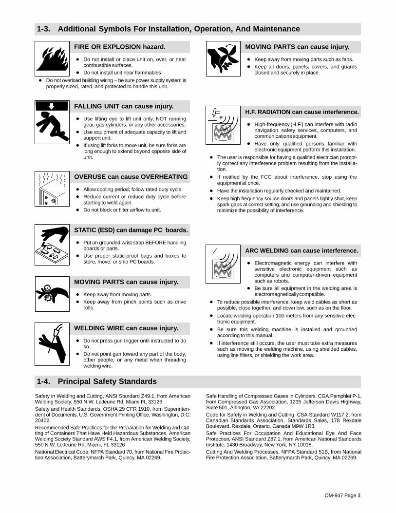
1-3. Additional Symbols For Installation, Operation, And Maintenance
FIRE OR EXPLOSION hazard.
� Do not install or place unit on, over, or nearcombustible surfaces.
� Do not install unit near flammables.
� Do not overload building wiring – be sure power supply system isproperly sized, rated, and protected to handle this unit.
FALLING UNIT can cause injury.
� Use lifting eye to lift unit only, NOT runninggear, gas cylinders, or any other accessories.
� Use equipment of adequate capacity to lift andsupport unit.
� If using lift forks to move unit, be sure forks arelong enough to extend beyond opposite side ofunit.
OVERUSE can cause OVERHEATING
� Allow cooling period; follow rated duty cycle.� Reduce current or reduce duty cycle before
starting to weld again.� Do not block or filter airflow to unit.
STATIC (ESD) can damage PC boards.
� Put on grounded wrist strap BEFORE handlingboards or parts.
� Use proper static-proof bags and boxes tostore, move, or ship PC boards.
MOVING PARTS can cause injury.
� Keep away from moving parts.� Keep away from pinch points such as drive
rolls.
WELDING WIRE can cause injury.
� Do not press gun trigger until instructed to doso.
� Do not point gun toward any part of the body,other people, or any metal when threadingwelding wire.
MOVING PARTS can cause injury.
� Keep away from moving parts such as fans.� Keep all doors, panels, covers, and guards
closed and securely in place.
H.F. RADIATION can cause interference.
� High-frequency (H.F.) can interfere with radionavigation, safety services, computers, andcommunications equipment.
� Have only qualified persons familiar withelectronic equipment perform this installation.
� The user is responsible for having a qualified electrician prompt-ly correct any interference problem resulting from the installa-tion.
� If notified by the FCC about interference, stop using theequipment at once.
� Have the installation regularly checked and maintained.
� Keep high-frequency source doors and panels tightly shut, keepspark gaps at correct setting, and use grounding and shielding tominimize the possibility of interference.
ARC WELDING can cause interference.
� Electromagnetic energy can interfere withsensitive electronic equipment such ascomputers and computer-driven equipmentsuch as robots.
� Be sure all equipment in the welding area iselectromagnetically compatible.
� To reduce possible interference, keep weld cables as short aspossible, close together, and down low, such as on the floor.
� Locate welding operation 100 meters from any sensitive elec-tronic equipment.
� Be sure this welding machine is installed and groundedaccording to this manual.
� If interference still occurs, the user must take extra measuressuch as moving the welding machine, using shielded cables,using line filters, or shielding the work area.
1-4. Principal Safety Standards
Safety in Welding and Cutting, ANSI Standard Z49.1, from AmericanWelding Society, 550 N.W. LeJeune Rd, Miami FL 33126Safety and Health Standards, OSHA 29 CFR 1910, from Superinten-dent of Documents, U.S. Government Printing Office, Washington, D.C.20402.Recommended Safe Practices for the Preparation for Welding and Cut-ting of Containers That Have Held Hazardous Substances, AmericanWelding Society Standard AWS F4.1, from American Welding Society,550 N.W. LeJeune Rd, Miami, FL 33126National Electrical Code, NFPA Standard 70, from National Fire Protec-tion Association, Batterymarch Park, Quincy, MA 02269.
Safe Handling of Compressed Gases in Cylinders, CGA Pamphlet P-1,from Compressed Gas Association, 1235 Jefferson Davis Highway,Suite 501, Arlington, VA 22202.Code for Safety in Welding and Cutting, CSA Standard W117.2, fromCanadian Standards Association, Standards Sales, 178 RexdaleBoulevard, Rexdale, Ontario, Canada M9W 1R3.Safe Practices For Occupation And Educational Eye And FaceProtection, ANSI Standard Z87.1, from American National StandardsInstitute, 1430 Broadway, New York, NY 10018.Cutting And Welding Processes, NFPA Standard 51B, from NationalFire Protection Association, Batterymarch Park, Quincy, MA 02269.

OM-947 Page 4
1-5. EMF Information
Considerations About Welding And The Effects Of Low FrequencyElectric And Magnetic FieldsWelding current, as it flows through welding cables, will cause electro-magnetic fields. There has been and still is some concern about suchfields. However, after examining more than 500 studies spanning 17years of research, a special blue ribbon committee of the NationalResearch Council concluded that: “The body of evidence, in thecommittee’s judgment, has not demonstrated that exposure to power-frequency electric and magnetic fields is a human-health hazard.”However, studies are still going forth and evidence continues to beexamined. Until the final conclusions of the research are reached, youmay wish to minimize your exposure to electromagnetic fields whenwelding or cutting.To reduce magnetic fields in the workplace, use the followingprocedures:
1. Keep cables close together by twisting or taping them.
2. Arrange cables to one side and away from the operator.
3. Do not coil or drape cables around your body.
4. Keep welding power source and cables as far away from opera-tor as practical.
5. Connect work clamp to workpiece as close to the weld as possi-ble.
About Pacemakers:Pacemaker wearers consult your doctor first. If cleared by your doctor,then following the above procedures is recommended.

OM-947 Page 5
SECTION 1 – CONSIGNES DE SECURITE – LIRE AVANTUTILISATION
som _nd_fre 4/98
1-1. Signification des symboles
Signifie Mise en garde ! Soyez vigilant ! Cette procédureprésente des risques de danger ! Ceux-ci sont identifiéspar des symboles adjacents aux directives.
� Identifie un message de sécurité particulier.
� Signifie NOTA ; n’est pas relatif à la sécurité.
Ce groupe de symboles signifie Mise en garde ! Soyez vigilant ! Il y a desrisques de danger reliés aux CHOCS ÉLECTRIQUES, aux PIÈCES ENMOUVEMENT et aux PIÈCES CHAUDES. Reportez-vous aux symboleset aux directives ci-dessous afin de connaître les mesures à prendre pouréviter tout danger.
1-2. Dangers relatifs au soudage à l’arc
� Les symboles présentés ci-après sont utilisés tout au long duprésent manuel pour attirer votre attention et identifier les risquesde danger. Lorsque vous voyez un symbole, soyez vigilant etsuivez les directives mentionnées afin d’éviter tout danger. Lesconsignes de sécurité présentées ci-après ne font que résumerl’information contenue dans les normes de sécurité énuméréesà la section 1-4. Veuillez lire et respecter toutes ces normes desécurité.
� L’installation, l’utilisation, l’entretien et les réparations ne doi-vent être confiés qu’à des personnes qualifiées.
� Au cours de l’utilisation, tenir toute personne à l’écart et plus par-ticulièrement les enfants.
UN CHOC ÉLECTRIQUE peut tuer.
Un simple contact avec des pièces électriques peutprovoquer une électrocution ou des blessures graves.L’électrode et le circuit de soudage sont sous tensiondès que l’appareil est sur ON. Le circuit d’entrée et lescircuits internes de l’appareil sont également sous
tension à ce moment-là. En soudage semi-automatique ou automatique,le fil, le dévidoir, le logement des galets d’entraînement et les piècesmétalliques en contact avec le fil de soudage sont sous tension. Desmatériels mal installés ou mal mis à la terre présentent un danger.
� Ne jamais toucher les pièces électriques sous tension.� Porter des gants et des vêtements de protection secs ne comportant
pas de trous.� S’isoler de la pièce et de la terre au moyen de tapis ou d’autres
moyens isolants suffisamment grands pour empêcher le contact phy-sique éventuel avec la pièce ou la terre.
� Ne pas se servir de source électrique àcourant électrique dans les zoneshumides, dans les endroits confinés ou là où on risque de tomber.
� Se servir d’une source électrique àcourant électrique UNIQUEMENT si leprocédé de soudage le demande.
� Si l’utilisation d’une source électrique àcourant électrique s’avère néces-saire, se servir de la fonction de télécommande si l’appareil en est équipé.
� Couper l’alimentation ou arrêter le moteur avant de procéder à l’instal-lation, à la réparation ou à l’entretien de l’appareil. Déverrouillerl’alimentation selon la norme OSHA 29 CFR 1910.147 (voir normes desécurité).
� Installer et mettre à la terre correctement cet appareil conformément àson manuel d’utilisation et aux codes nationaux, provinciaux etmunicipaux.
� Toujours vérifier la terre du cordon d’alimentation – Vérifier et s’assu-rer que le fil de terre du cordon d’alimentation est bien raccordé à laborne de terre du sectionneur ou que la fiche du cordon est raccordéeà une prise correctement mise à la terre.
� En effectuant les raccordements d’entrée fixer d’abord le conducteurde mise à la terre approprié et contre-vérifier les connexions.
� Vérifier fréquemment le cordon d’alimentation pour voir s’il n’est pasendommagé ou dénudé – remplacer le cordon immédiatement s’il estendommagé – un câble dénudé peut provoquer une électrocution.
� Mettre l’appareil hors tension quand on ne l’utilise pas.� Ne pas utiliser des câbles usés, endommagés, de grosseur insuffi-
sante ou mal épissés.� Ne pas enrouler les câbles autour du corps.� Si la pièce soudée doit être mise à la terre, le faire directement avec un
câble distinct.� Ne pas toucher l’électrode quand on est en contact avec la pièce, la
terre ou une électrode provenant d’une autre machine.
� N’utiliser qu’un matériel en bon état. Réparer ou remplacer sur-le-champ les pièces endommagées. Entretenir l’appareil conformémentà ce manuel.
� Porter un harnais de sécurité quand on travaille en hauteur.
� Maintenir solidement en place tous les panneaux et capots.
� Fixer le câble de retour de façon à obtenir un bon contact métal-métalavec la pièce à souder ou la table de travail, le plus près possible de lasoudure.
� Isoler la pince de masse quand pas mis à la pièce pour éviter le contactavec tout objet métallique.
Il y a DU COURANT CONTINU IMPORTANT dans lesconvertisseurs après la suppression de l’alimenta-tion électrique.� Arrêter les convertisseurs, débrancher le courant électrique, et dé-
charger les condensateurs d’alimentation selon les instructionsindiquées dans la partie entretien avant de toucher les pièces.
Le soudage génère des fumées et des gaz. Leurinhalation peut être dangereux pour votre santé.
� Eloigner votre tête des fumées. Ne pas respirerles fumées.
� A l’intérieur, ventiler la zone et/ou utiliser un échappement au niveaude l’arc pour l’évacuation des fumées et des gaz de soudage.
� Si la ventilation est insuffisante, utiliser un respirateur à alimenta-tion d’air homologué.
� Lire les spécifications de sécurité des matériaux (MSDSs) et lesinstructions du fabricant concernant les métaux, les consomma-bles, les revêtements, les nettoyants et les dégraisseurs.
� Travailler dans un espace fermé seulement s’il est bien ventilé ou enportant un respirateur à alimentation d’air. Demander toujours à unsurveillant dûment formé de se tenir à proximité. Des fumées et desgaz de soudage peuvent déplacer l’air et abaisser le niveau d’oxy-gène provoquant des blessures ou des accidents mortels. S’assu-rer que l’air de respiration ne présente aucun danger.
� Ne pas souder dans des endroits situés à proximité d’opérations dedégraissage, de nettoyage ou de pulvérisation. La chaleur et lesrayons de l’arc peuvent réagir en présence de vapeurs et former desgaz hautement toxiques et irritants.
� Ne pas souder des métaux munis d’un revêtement, tels que l’aciergalvanisé, plaqué en plomb ou au cadmium à moins que le revête-ment n’ait été enlevé dans la zone de soudure, que l’endroit soit bienventilé, et si nécessaire, en portant un respirateur à alimentationd’air. Les revêtements et tous les métaux renfermant ces élémentspeuvent dégager des fumées toxiques en cas de soudage.
LES FUMÉES ET LES GAZ peuventêtre dangereux.

OM-947 Page 6
Le rayonnement de l’arc du procédé de soudagegénère des rayons visibles et invisibles intenses(ultraviolets et infrarouges) susceptibles de provoquer
des brûlures dans les yeux et sur la peau. Des étincelles sont projetéespendant le soudage.
LES RAYONS DE L’ARC peuvent pro-voquer des brûlures dans les yeux etsur la peau.
� Porter un casque de soudage muni d’un écran de filtre approprié pourprotéger votre visage et vos yeux pendant le soudage ou pour regar-der (voir ANSI Z49.1 et Z87.1 énuméré dans les normes de sécurité).
� Porter des protections approuvés pour les oreilles si le niveau sondre esttrop élevé.
� Utiliser des écrans ou des barrières pour protéger des tiers de l’éclairet de l’éblouissement; demander aux autres personnes de ne pas re-garder l’arc.
� Porter des vêtements de protection constitué dans une matière dura-ble, résistant au feu (cuir ou laine) et une protection des pieds.
Le soudage effectué sur des conteneurs fermés telsque des réservoirs, tambours ou des conduites peutprovoquer leur éclatement. Des étincelles peuvent êtreprojetées de l’arc de soudure. La projection d’étincel-
les, des pièces chaudes et des équipements chauds peut provoquer desincendies et des brûlures. Le contact accidentel de l’électrode avec desobjets métalliques peut provoquer des étincelles, une explosion, unsurchauffement ou un incendie. Avant de commencer le soudage, vérifieret s’assurer que l’endroit ne présente pas de danger.
LE SOUDAGE peut provoquer unincendie ou une explosion.
� Se protéger et d’autres personnes de la projection d’étincelles et demétal chaud.
� Ne pas souder dans un endroit là où des étincelles peuvent tomber surdes substances inflammables.
� Déplacer toutes les substances inflammables à une distance de 10,7m de l’arc de soudage. En cas d’impossibilité les recouvrir soigneuse-ment avec des protections homologués.
� Des étincelles et des matériaux chauds du soudage peuvent facile-ment passer dans d’autres zones en traversant de petites fissures etdes ouvertures.
� Surveiller tout déclenchement d’incendie et tenir un extincteur à proxi-mité.
� Le soudage effectué sur un plafond, plancher, paroi ou séparationpeut déclencher un incendie de l’autre côté.
� Ne pas effectuer le soudage sur des conteneurs fermés tels que desréservoirs, tambours, ou conduites, à moins qu’ils n’aient été prépa-rés correctement conformément à AWS F4.1 (voir les normes desécurité).
� Brancher le câble sur la pièce le plus près possible de la zone de sou-dage pour éviter le transport du courant sur une longue distance pardes chemins inconnus éventuels en provoquant des risques d’élec-trocution et d’incendie.
� Ne pas utiliser le poste de soudage pour dégeler des conduites ge-lées.
� En cas de non utilisation, enlever la baguette d’électrode du porte-électrode ou couper le fil à la pointe de contact.
� Porter des vêtements de protection dépourvus d’huile tels que desgants en cuir, une chemise en matériau lourd, des pantalons sans re-vers, des chaussures hautes et un couvre chef.
� Avant de souder, retirer toute substance combustible de vos pochestelles qu’un allumeur au butane ou des allumettes.
DES PARTICULES VOLANTESpeuvent blesser les yeux.
� Le soudage, l’écaillement, le passage de la pièceà la brosse en fil de fer, et le meulage génèrentdes étincelles et des particules métalliques vo-
lantes. Pendant la période de refroidissement des soudures, elles ris-quent de projeter du laitier.� Porter des lunettes de sécurité avec écrans latéraux ou un écran facial.
LES ACCUMULATIONS DE GAZ ris-quent de provoquer des blessures oumême la mort.
� Fermer l’alimentation du gaz protecteur en cas denon utilisation.
� Veiller toujours à bien aérer les espaces confinés ou se servir d’un respi-rateur d’adduction d’air homologué.
DES PIÈCES CHAUDES peuvent pro-voquer des brûlures graves.
� Ne pas toucher des parties chaudes à mains nues� Prévoir une période de refroidissement avant
d’utiliser le pistolet ou la torche.
LES CHAMPS MAGNÉTIQUES peuventaffecter les stimulateurs cardiaques.
� Porteurs de stimulateur cardiaque, restez à distance.� Les porteurs d’un stimulateur cardiaque doivent
d’abord consulter leur médecin avant de s’approcherdes opérations de soudage à l’arc, de gougeage oude soudage par points.
LE BRUIT peut affecter l’ouïe.
Le bruit des processus et des équipements peut affecterl’ouïe.
� Porter des protections approuvés pour les oreilles sile niveau sondre est trop élevé.
Des bouteilles de gaz protecteur contiennent du gazsous haute pression. Si une bouteille est endomma-gée, elle peut exploser. Du fait que les bouteilles de gazfont normalement partie du procédé de soudage, les
manipuler avec précaution.
� Protéger les bouteilles de gaz comprimé d’une chaleur excessive,des chocs mécaniques, du laitier, des flammes ouvertes, des étin-celles et des arcs.
� Placer les bouteilles debout en les fixant dans un support stationnai-re ou dans un porte-bouteilles pour les empêcher de tomber ou dese renverser.
� Tenir les bouteilles éloignées des circuits de soudage ou autres cir-cuits électriques.
� Ne jamais placer une torche de soudage sur une bouteille à gaz.� Une électrode de soudage ne doit jamais entrer en contact avec une
bouteille.� Ne jamais souder une bouteille pressurisée – risque d’explosion.� Utiliser seulement des bouteilles de gaz protecteur, régulateurs,
tuyaux et raccords convenables pour cette application spécifique;les maintenir ainsi que les éléments associés en bon état.
� Ne pas tenir la tête en face de la sortie en ouvrant la soupape de labouteille.
� Maintenir le chapeau de protection sur la soupape, sauf en cas d’uti-lisation ou de branchement de la bouteille.
� Lire et suivre les instructions concernant les bouteilles de gaz com-primé, les équipements associés et les publications P-1 CGA énu-mérées dans les normes de sécurité.
Si des BOUTEILLES sont endomma-gées, elles pourront exploser.

OM-947 Page 7
1-3. Dangers supplémentaires en relation avec l’installation, le fonctionnementet la maintenance
Risque D’INCENDIE OUD’EXPLOSION.
� Ne pas placer l’appareil sur, au-dessus ou à proxi-mité de surfaces infllammables.
� Ne pas installer l’appareil à proximité de produits inflammables� Ne pas surcharger l’installation électrique – s”assurer que l’alimen-
tation est correctement dimensionné et protégé avant de mettrel’appareil en service.
LA CHUTE DE L’APPAREIL peutblesser.
� Utiliser l’anneau de levage uniquement pour sou-lever l’appareil, NON PAS les chariot, les bouteil-les de gaz ou tout autre accessoire.
� Utiliser un engin d’une capacité appropriée poursoulever l’appareil.
� En utilisant des fourches de levage pour déplacer l’unité, s’assurerque les fourches sont suffisamment longues pour dépasser du côtéopposé de l’appareil.
L’EMPLOI EXCESSIF peutSURCHAUFFER L’ÉQUIPEMENT.
� Prévoir une période de refroidissement, respec-ter le cycle opératoire nominal.
� Réduire le courant ou le cycle opératoire avant derecommancer le soudage.
� Ne pas obstruer les passages d’air du poste.
LES CHARGES ÉLECTROSTATI-QUES peuvent endommager les cir-cuits imprimés.
� Établir la connexion avec la barrette de terreavant de manipuler des cartes ou des pièces.
� Utiliser des pochettes et des boîtes antistatiquespour stocker, déplacer ou expédier des cartes decircuits imprimes.
DES ORGANES MOBILES peuventprovoquer des blessures.
� Ne pas s’approcher des organes mobiles.� Ne pas s’approcher des points de coincement
tels que des rouleaux de commande.
LES FILS DE SOUDAGE peuvent pro-voquer des blessures.
� Ne pas appuyer sur la gachette avant d’en avoirreçu l’instruction.
� Ne pas diriger le pistolet vers soi, d’autres person-nes ou toute pièce mécanique en engageant le filde soudage.
DES ORGANES MOBILES peuventprovoquer des blessures.
� Rester à l’écart des organes mobiles comme leventilateur.
� Maintenir fermés et fixement en place les portes,panneaux, recouvrements et dispositifs deprotection.
LE RAYONNEMENT HAUTE FRÉ-QUENCE (H.F.) risque de provoquerdes interférences.
� Le rayonnement haute frequence peut provoquerdes interférences avec les équipements de ra-dio–navigation et de communication, les servicesde sécurité et les ordinateurs.
� Demander seulement à des personnes qualifiées familiariséesavec des équipements électroniques de faire fonctionner l’installa-tion.
� L’utilisateur est tenu de faire corriger rapidement par un électricienqualifié les interférences résultant de l’installation.
� Si le FCC signale des interférences, arrêter immédiatement l’appa-reil.
� Effectuer régulièrement le contrôle et l’entretien de l’installation.� Maintenir soigneusement fermés les portes et les panneaux des
sources de haute fréquence, maintenir les éclateurs à une distancecorrecte et utiliser une terre et et un blindage pour réduire les interfé-rences éventuelles.
LE SOUDAGE À L’ARC risque deprovoquer des interférences.
� L’énergie électromagnétique risque de provoquerdes interférences pour l’équipement électroniquesensible tel que les ordinateurs et l’équipementcommandé par ordinateur tel que les robots.
� Veiller à ce que tout l’équipement de la zone de soudage soit com-patible électromagnétiquement.
� Pour réduire la possibilité d’interférence, maintenir les câbles desoudage aussi courts que possible, les grouper, et les poser aussibas que possible (ex. par terre).
� Veiller à souder à une distance de 100 mètres de tout équipementélectronique sensible.
� Veiller à ce que ce poste de soudage soit posé et mis à la terreconformément à ce mode d’emploi.
� En cas d’interférences après avoir pris les mesures précédentes, ilincombe à l’utilisateur de prendre des mesures supplémentaires tel-les que le déplacement du poste, l’utilisation de câbles blindés, l’uti-lisation de filtres de ligne ou la pose de protecteurs dans la zone detravail.
LES CHAMPS MAGNÉTIQUES peuventaffecter les stimulateurs cardiaques.
� Porteurs de stimulateur cardiaque, restez à dis-tance.
� Les porteurs d’un stimulateur cardiaque doiventd’abord consulter leur médecin avant de s’appro-cher des opérations de soudage à l’arc, de gou-geage ou de soudage par points.

OM-947 Page 8
1-4. Principales normes de sécurité
Safety in Welding and Cutting, norme ANSI Z49.1, de l’American Wel-ding Society, 550 N.W. Lejeune Rd, Miami FL 33126
Safety and Health Sandards, OSHA 29 CFR 1910, du Superintendentof Documents, U.S. Government Printing Office, Washington, D.C.20402.
Recommended Safe Practice for the Preparation for Welding and Cut-ting of Containers That Have Held Hazardous Substances, norme AWSF4.1, de l’American Welding Society, 550 N.W. Lejeune Rd, Miami FL33126
National Electrical Code, NFPA Standard 70, de la National Fire Protec-tion Association, Batterymarch Park, Quincy, MA 02269.
Safe Handling of Compressed Gases in Cylinders, CGA Pamphlet P-1,de la Compressed Gas Association, 1235 Jefferson Davis Highway,Suite 501, Arlington, VA 22202.
Règles de sécurité en soudage, coupage et procédés connexes, normeCSA W117.2, de l’Association canadienne de normalisation, vente denormes, 178 Rexdale Boulevard, Rexdale (Ontario) Canada M9W 1R3.
Safe Practices For Occupation And Educational Eye And Face Protec-tion, norme ANSI Z87.1, de l’American National Standards Institute,1430 Broadway, New York, NY 10018.
Cutting and Welding Processes, norme NFPA 51B, de la National FireProtection Association, Batterymarch Park, Quincy, MA 02269.
1-5. Information sur les champs électromagnétiques
Données sur le soudage électrique et sur les effets, pour l’organisme,des champs magnétiques basse fréquence
Le courant de soudage, pendant son passage dans les câbles de sou-dage, causera des champs électromagnétiques. Il y a eu et il y a encoreun certain souci à propos de tels champs. Cependant, après avoir ex-aminé plus de 500 études qui ont été faites pendant une période derecherche de 17 ans, un comité spécial ruban bleu du National Re-search Council a conclu: “L’accumulation de preuves, suivant lejugement du comité, n’a pas démontré que l’exposition aux champsmagnétiques et champs électriques à haute fréquence représente unrisque à la santé humaine”. Toutefois, des études sont toujours en courset les preuves continuent à être examinées. En attendant que les con-clusions finales de la recherche soient établies, il vous seraitsouhaitable de réduire votre exposition aux champs électromagnéti-ques pendant le soudage ou le coupage.
Afin de réduire les champs électromagnétiques dans l’environnementde travail, respecter les consignes suivantes :
1 Garder les câbles ensembles en les torsadant ou en lesattachant avec du ruban adhésif.
2 Mettre tous les câbles du côté opposé de l’opérateur.
3 Ne pas courber pas et ne pas entourer pas les câbles autour devotre corps.
4 Garder le poste de soudage et les câbles le plus loin possible devous.
5 Relier la pince de masse le plus près possible de la zone desoudure.
Consignes relatives aux stimulateurs cardiaques :
Les personnes qui portent un stimulateur cardiaque doivent avant toutconsulter leur docteur. Si vous êtes déclaré apte par votre docteur, il estalors recommandé de respecter les consignes ci–dessus.

OM-947 Page 9
SECTION 2 – SPECIFICATIONS
2-1. Specifications
Rated WeldingOutput
AmperageRange
Maximum Open-Circuit Voltage
DC
Amperes Input atRated Load Output115 V, 60 Hz, Single-
Phase
KVA KWWeightW/ Gun
Overall Dimensions
90 A @ 19 Volts DC,20% Duty Cycle
63 A @ 21 Volts DC,20% Duty Cycle*
30 – 125 2920
15*
2.90
2.20*
2.50
1.77*
50 lb(22.7 kg)
Length: 16-7/8 in(429 mm)
Width: 9-7/8 in(251 mm)
Height: 12-1/8 in(308 mm)
Wire TypeAnd Dia
Flux Cored Solid/Stainless** Wire Feed Speed Range
Wire TypeAnd Dia .030 – .035 in
(0.8 – 0.9 mm).024 – .030 in(0.6 – 0.8 mm)
0 – 500 IPM (0 – 13 m/min) At No Load0 – 415 IPM (0 – 11 m/min) Feeding Wire
* CSA Rating
** When shielding gas is required, gas solenoid valve must be installed.
2-2. Duty Cycle And Overheating
Duty Cycle is percentage of 10 min-utes that unit can weld at rated loadwithout overheating.
If unit overheats, thermostat(s)opens, output stops, and coolingfan runs. Wait fifteen minutes forunit to cool. Reduce amperage orduty cycle before welding.
� Exceeding duty cycle candamage unit or gun and voidwarranty.
Overheating
0
15
A or V
ORReduce Duty Cycle
Minutesduty1 4/95 – 210 517
20% duty cycle at 90 amps
2 Minutes Welding 8 Minutes Resting
Duty Cycle %
Ou
tpu
t Am
per
es
1 4 10 20 40 60 1002 6 80810
20
40
60
80100
200
135
OM-947 Page 10
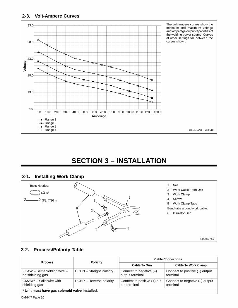
2-3. Volt-Ampere Curves
The volt-ampere curves show theminimum and maximum voltageand amperage output capabilities ofthe welding power source. Curvesof other settings fall between thecurves shown.
ssb1.1 10/91 – 210 518
8.0
13.0
18.0
23.0
28.0
33.0
0.0 10.0 20.0 30.0 40.0 50.0 60.0 70.0 80.0 90.0 100.0 110.0 120.0 130.0Amperage
Vo
ltag
e
Range 1Range 2Range 3Range 4
SECTION 3 – INSTALLATION
3-1. Installing Work Clamp
1 Nut
2 Work Cable From Unit
3 Work Clamp
4 Screw
5 Work Clamp Tabs
Bend tabs around work cable.
6 Insulator Grip
Ref. 802 456
1
2
3
45
Tools Needed:
3/8, 7/16 in
6
3-2. Process/Polarity Table
Process PolarityCable Connections
Process PolarityCable To Gun Cable To Work Clamp
FCAW – Self-shielding wire –no shielding gas
DCEN – Straight Polarity Connect to negative (–)output terminal
Connect to positive (+) outputterminal
GMAW* – Solid wire withshielding gas
DCEP – Reverse polarity Connect to positive (+) out-put terminal
Connect to negative (–) outputterminal
* Unit must have gas solenoid valve installed.
OM-947 Page 11
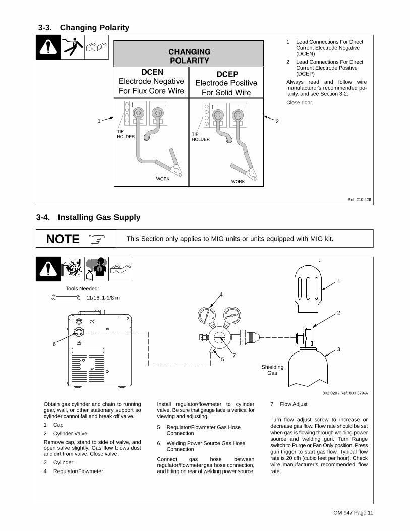
3-3. Changing Polarity
1 Lead Connections For DirectCurrent Electrode Negative(DCEN)
2 Lead Connections For DirectCurrent Electrode Positive(DCEP)
Always read and follow wiremanufacturer’s recommended po-larity, and see Section 3-2.
Close door.
Ref. 210 428
1 2
3-4. Installing Gas Supply
This Section only applies to MIG units or units equipped with MIG kit.NOTE
Obtain gas cylinder and chain to runninggear, wall, or other stationary support socylinder cannot fall and break off valve.
1 Cap
2 Cylinder Valve
Remove cap, stand to side of valve, andopen valve slightly. Gas flow blows dustand dirt from valve. Close valve.
3 Cylinder
4 Regulator/Flowmeter
Install regulator/flowmeter to cylindervalve. Be sure that gauge face is vertical forviewing and adjusting.
5 Regulator/Flowmeter Gas HoseConnection
6 Welding Power Source Gas HoseConnection
Connect gas hose betweenregulator/flowmeter gas hose connection,and fitting on rear of welding power source.
7 Flow Adjust
Turn flow adjust screw to increase ordecrease gas flow. Flow rate should be setwhen gas is flowing through welding powersource and welding gun. Turn Rangeswitch to Purge or Fan Only position. Pressgun trigger to start gas flow. Typical flowrate is 20 cfh (cubic feet per hour). Checkwire manufacturer’s recommended flowrate.
Tools Needed:
802 028 / Ref. 803 379-A
11/16, 1-1/8 in
6
4
57
1
2
3
ShieldingGas

OM-947 Page 12
3-5. Installing Wire Spool And Adjusting Hub Tension
When a slight force is neededto turn spool, tension is set.
1/2 in
Tools Needed:
802 971 / 803 012 / 803 013 -A
Installing 8 in (203 mm) Wire Spool
Installing 4 in (102 mm) Wire Spool
When a slight force is neededto turn spool, tension is set.
Retaining ring usedwith 8 in (203 mm)
spool only.
Adapter used with8 in (203 mm)
spool only.
Use supplied spacer ifspool does not stay onadapter locating pin.
� Only applies to units equipped withoptional hub kit.
OM-947 Page 13
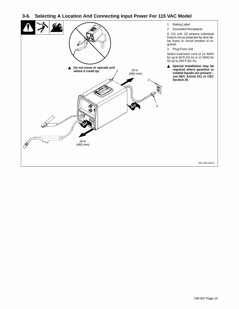
3-6. Selecting A Location And Connecting Input Power For 115 VAC Model
1 Rating Label
2 Grounded Receptacle
A 115 volt, 20 ampere individualbranch circuit protected by time-de-lay fuses or circuit breaker is re-quired.
3 Plug From Unit
Select extension cord of 14 AWGfor up to 50 ft (15 m) or 12 AWG for50 up to 200 ft (61 m).
� Special installation may berequired where gasoline orvolatile liquids are present –see NEC Article 511 or CECSection 20.
18 in(460 mm)
18 in(460 mm)
Ref. 803 443-A
1
2
3
� Do not move or operate unitwhere it could tip.

OM-947 Page 14
3-7. Threading Welding Wire
1 Wire Spool
2 Welding Wire
3 Inlet Wire Guide
4 Pressure Adjustment Knob
5 Drive Roll
6 Gun Cable
Lay gun cable out straight.
Tools Needed:
61
Pull and hold wire; cut off end.
4 in(102 mm)
Remove gun nozzle and contact tip.
Open pressure assembly. Push wire thru guides into gun liner;continue to hold wire.
� Hold wire tightly to keep itfrom unraveling.
Ref. 803 444-A / Ref. 205 837
WOOD
Feed wire to check drive roll pressure.Tighten knob enough to prevent slipping.
Cut off wire. Close door.
Press gun trigger until wire comesout of gun.
2
Turn power on.
INPUTPOWER
6 in(150 mm)
Tighten� Rotate pressure adjustment
knob in a clockwise directionuntil drive roll is tight againstthe welding wire. Adjustdrive roll pressure just tightlyenough to prevent wire fromslipping on or against driveroll during operation.
Tighten
Be sure that wire is positionedin proper feed roll groove.
Close and tighten pressure assembly, and let go of wire.
Be sure that contact tip matches wire diameter.Reinstall tip adapter, if applicable, contact tipand nozzle.
3 5
4
� Tip adapter may also require removalto allow wire to feed out end of gun.

OM-947 Page 15
SECTION 4 – OPERATION4-1. Controls
1 Voltage Switch
Use control to select the weldvoltage range. As the thickness ofmaterial increases, a higher voltagerange must be selected (see weldsetting label in welding powersource or Section 4-2 asapplicable). Do not switch underload.
� Switch must “click” into detentposition 1, 2, 3, 4, or purge forproper contact.
2 Voltage Switch - Fan Only OrPurge Position
Fan runs but there is no weldoutput.
3 Wire Feed Control
Use control to select a wire feedspeed. As Voltage switch setting in-creases, wire speed range also in-creases (see weld setting label inwelding power source or Section4-2 as applicable).
4 Power Switch
Ref. 210 427
21
3
4

OM-947 Page 16
4-2. Weld Parameter Chart

OM-947 Page 17
210 428

OM-947 Page 18
SECTION 5 – MAINTENANCE &TROUBLESHOOTING
5-1. Routine Maintenance
� Disconnect power before maintaining.
3 Months
Replaceunreadablelabels.
Repair orreplacecrackedweld cable.
Clean andtighten weldterminals.
6 Months
Blow out orvacuum inside.During heavyservice, cleanmonthly.
Or
5-2. Overload Protection
803 379-A
1 Circuit Breaker CB1
CB1 protects unit from overload. IfCB1 opens, unit shuts down.
Reset breaker.1
5-3. Drive Motor Protection
Drive motor protection circuit protects drive motor from overload. If drive motor becomes inoperative, release guntrigger and wait until protection circuit resets allowing drive motor to feed wire again.
OM-947 Page 19
5-4. Changing Drive Roll Or Wire Inlet Guide
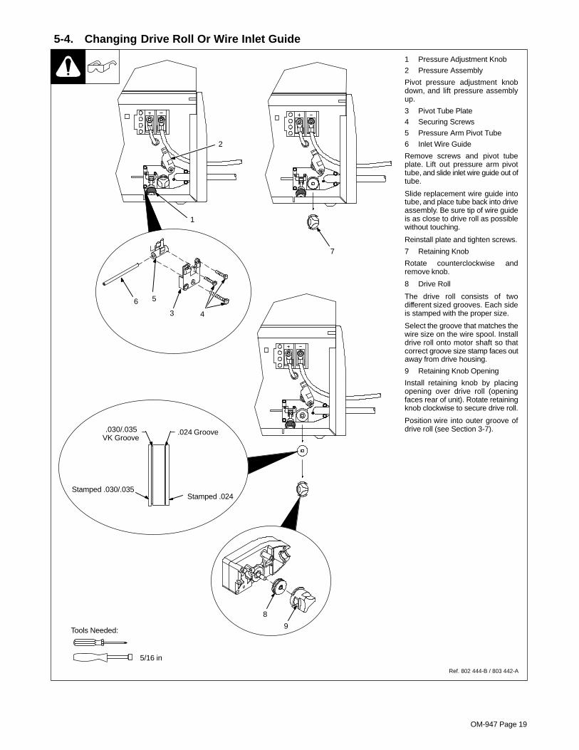
1 Pressure Adjustment Knob
2 Pressure Assembly
Pivot pressure adjustment knobdown, and lift pressure assemblyup.
3 Pivot Tube Plate4 Securing Screws
5 Pressure Arm Pivot Tube
6 Inlet Wire Guide
Remove screws and pivot tubeplate. Lift out pressure arm pivottube, and slide inlet wire guide out oftube.
Slide replacement wire guide intotube, and place tube back into driveassembly. Be sure tip of wire guideis as close to drive roll as possiblewithout touching.
Reinstall plate and tighten screws.
7 Retaining Knob
Rotate counterclockwise andremove knob.
8 Drive Roll
The drive roll consists of twodifferent sized grooves. Each sideis stamped with the proper size.
Select the groove that matches thewire size on the wire spool. Installdrive roll onto motor shaft so thatcorrect groove size stamp faces outaway from drive housing.
9 Retaining Knob Opening
Install retaining knob by placingopening over drive roll (openingfaces rear of unit). Rotate retainingknob clockwise to secure drive roll.
Position wire into outer groove ofdrive roll (see Section 3-7).
Tools Needed:
Ref. 802 444-B / 803 442-A
.024 Groove.030/.035VK Groove
Stamped .024Stamped .030/.035
1
3 4
56
2
7
5/16 in
8
9

OM-947 Page 20
5-5. Replacing Gun Contact Tip
� Turn Off power beforereplacing contact tip.
1 Tip Adapter
2 Contact Tip
3 Nozzle
Cut off welding wire at contact tip.Remove nozzle.
Remove contact tip from tip adapterand install new contact tip. Reinstallnozzle.
Tools Needed:
12
3
OM-947 Page 21
5-6. Cleaning Or Replacing Gun Liner
8 mm / 10mm
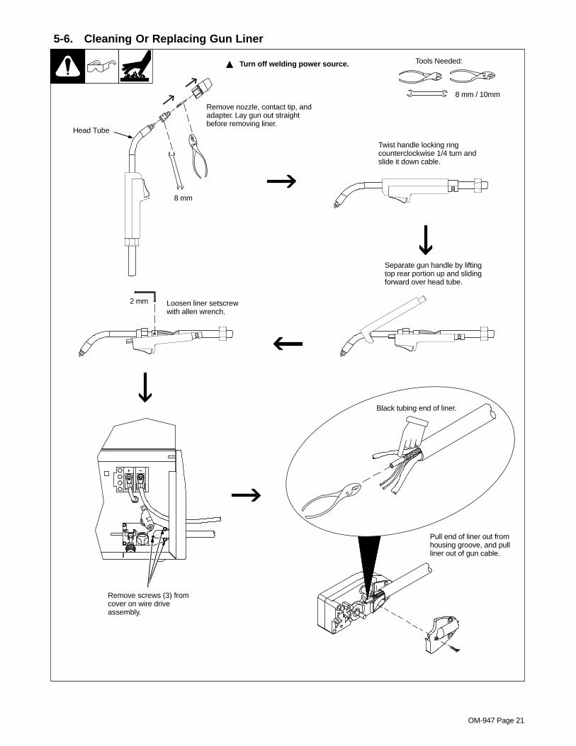
� Turn off welding power source. Tools Needed:
Remove screws (3) fromcover on wire driveassembly.
Head Tube
8 mm
Remove nozzle, contact tip, andadapter. Lay gun out straightbefore removing liner.
Twist handle locking ringcounterclockwise 1/4 turn andslide it down cable.
Separate gun handle by liftingtop rear portion up and slidingforward over head tube.
2 mm Loosen liner setscrewwith allen wrench.
Pull end of liner out fromhousing groove, and pullliner out of gun cable.
Black tubing end of liner.

OM-947 Page 22
5-6. Cleaning Or Replacing Gun Liner (Continued)
Reinstall cover onto wiredrive assembly, and securewith screws (3).
8 mm
When liner exits cable at gunhandle, guide liner into headtube. Continue to push liner untilit exits end of head tube.
Lower top portion of handle ontobottom of handle. Slide lockingring over rear of handle, andsecure with by twisting ringclockwise 1/4 turn.
Slide top portion of handle overhead tube.
2 mm
Be sure that cable is straight.Tighten liner setscrew withallen wrench. Cut liner sothat 3/4 in (19 mm) sticks outof head tube.
Black tubing end of liner.
Lay gun cable straight on a flatsurface. Insert bare end of liner(end without black tubing) intowire drive end of cable. Pushliner toward gun. If necessary,twist cable to ease installation.
Reinstall cable end into drivehousing with retaining ring betweenthe two locating ribs. Position liner ingroove so that black tubing end isflush with back of groove.
3/4 in(19 mm)
Reassemble gun by placinghead tube into bottom section ofhandle.
Thread welding wire throughgun (see Section 3-7). Reinstalladapter, contact tip, and nozzle.

OM-947 Page 23
5-7. Replacing Switch And/Or Head Tube
Tools Needed:
8 mm, 11/16 in
Remove nozzle, contact tip, and adapter.Secure head tube in vice. Loosen cableconnector. Remove from vice and turnhead tube out by hand.
Hand-tighten head tube into cableconnector. Place head tube in vice andtighten until cable connector is tight.
� Turn Off welding power source.
Twist handle locking ringcounterclockwise 1/4 turn andslide it down cable.
Separate gun handle by liftingtop rear portion up and slidingforward over head tube.
Slide trigger assembly forwardand out of lower portion of handle.Disconnect leads. Install newswitch and connect leads (polarityis not important). Reassemble inreverse order. If replacing headtube, continue to end of figure.
8 mm
Lower top portion of handle ontobottom of handle. Slide lockingring over rear of handle, andsecure with by twisting ringclockwise 1/4 turn.
Slide top portion of handle overhead tube.
Reassemble gun by placinghead tube into bottom section ofhandle.
Thread welding wire throughgun (see Section 3-7). Reinstalladapter, contact tip, and nozzle.

OM-947 Page 24
5-8. Troubleshooting Table
Trouble Remedy
No weld output; wire does not feed; fandoes not run.
Secure power cord plug in receptacle (see Section 3-6).does not run.
Replace building line fuse or reset circuit breaker if open.
Place Power switch in On position (see Section 4-1).
Reset welding power source circuit breaker if open.
No weld output; wire does not feed; fanmotor continues to run.
Thermostat TP1 open (overheating). Allow fan to run with gun trigger switch off; thermostat closes whenunit has cooled (see Section 2-2).
Be sure that Voltage switch is not set between ranges (see Section 4-1).
Disassemble torch handle and check trigger switch lead connections, tighten or reconnect any looseconnections.
No weld output; wire feeds. Connect work clamp to get good metal to metal contact.
Replace contact tip (see Section 5-5).
Check for proper polarity connections (see Section 3-3).
Low weld output. Connect unit to proper input voltage or check for low line voltage.
Place voltage switch in desired position (see Section 4-1).
If using an extension cord, check that wire size and length is the proper size for power rating of weldingpower source (see Section 2-1).
Electrode wire feeding stops duringwelding.
Straighten gun cable and/or replace damaged parts.welding.
Adjust drive roll pressure (see Section 3-7).
Change to proper drive roll groove (see Section 5-4).
Readjust hub tension (see Section 3-5).
Replace contact tip if blocked (see Section 5-5).
Clean or replace wire inlet guide or liner if dirty or plugged (see Section 5-4).
Replace drive roll or pressure bearing if worn or slipping (see Section 5-4).
Check and clear any restrictions at drive assembly and liner (see Section 3-7).
Release gun trigger and allow gun and motor protection circuitry to reset.
Have nearest Factory Authorized Service Agent check drive motor.

OM-947 Page 25
SECTION 6 – ELECTRICAL DIAGRAM
210 513
Figure 6-1. Circuit Diagram

OM-947 Page 26
SECTION 7 – WIRE WELDING GUIDELINES
7-1. Typical FCAW Process Connections
� Weld current can damageelectronic parts in vehicles.Disconnect both batterycables before welding on avehicle. Place work clamp asclose to the weld as possible.
Wire Feeder/Power Source
Workpiece
Gun
Work Clamp
fcaw 1/2003 / Ref. 803 444-A
Self-Shielding FluxCore Wire
7-2. Typical MIG Process Connections
� Weld current can damageelectronic parts in vehicles.Disconnect both batterycables before welding on avehicle. Place work clamp asclose to the weld as possible.
Wire Feeder/Power Source
Workpiece
Gun
Regulator/Flowmeter
Gas HoseShieldingGas
Work Clamp
light mig 5/967 / Ref. 803 444-A
Solid Wire

OM-947 Page 27
7-3. Typical Control Settings
These settings are guidelines only. Material and wire type, joint design, fitup,position, etc. affect settings. Test welds to be sure they comply to specifications.
NOTE
3.5 x 125 A = 437 ipm
2 x 125 A = 250 ipm
1.6 x 125 A = 200 ipm
30 – 90 A
40 – 145 A
50 – 180 A
Convert MaterialThickness toAmperage (A)
Material thickness determines weldparameters.
.035 in
Recommendation Wire Speed(Approx.)
1/8 or 0.125 in
(0.001 in = 1 ampere)0.125 in = 125 A
Wire Size Amperage Range
0.023 in
0.030 in
0.035 in
Select Wire Size
WireSize
0.023 in
0.030 in
0.035 in
3.5 in per ampere
2 in per ampere
1.6 in per ampere
Select Wire Speed(Amperage)
125 A based on 1/8 inmaterial thickness
ipm = inches per minute
Low voltage: wire stubs into work
High voltage: arc is unstable (spatter)
Set voltage midway between high/low voltage
Select Voltage
Ref. 803 441-A
Voltage controls height and width ofweld bead.
Wire speed (amperage) controls weldpenetration (wire speed = burn-off rate)

OM-947 Page 28
7-4. Holding And Positioning Welding Gun
Welding wire is energized when gun trigger is pressed. Before lowering helmet andpressing trigger, be sure wire is no more than 1/2 in (13 mm) past end of nozzle,and tip of wire is positioned correctly on seam.
NOTE
1 Hold Gun and Control GunTrigger
2 Workpiece
3 Work Clamp
4 Electrode Extension (Stickout)1/4 to 1/2 in (6 To 13 mm)
5 Cradle Gun and Rest Hand onWorkpiece
23
5
4
90° 90°
0°-15°
45°
45°
1
0°-15°
S-0421-A
End View of Work Angle Side View of Gun Angle
GROOVE WELDS
End View of Work Angle Side View of Gun Angle
FILLET WELDS

OM-947 Page 29
7-5. Conditions That Affect Weld Bead Shape
Weld bead shape depends on gun angle, direction of travel, electrode extension(stickout), travel speed, thickness of base metal, wire feed speed (weld current),and voltage.
NOTE
Slow
FILLET WELD ELECTODE EXTENSIONS (STICKOUT)
ELECTRODE EXTENSIONS (STICKOUT)
GUN ANGLES AND WELD BEAD PROFILES
10° 10°
GUN TRAVEL SPEED S-0634
Push Perpendicular Drag or Pull
Short Normal Long
Short Normal Long
Normal Fast
Electrode directedahead of bead
Electrode pointedback into bead
Direction Of Welding
� The Drag or Pull technique is generally recommended when welding with flux-cored tubular wire.
OM-947 Page 30
7-6. Gun Movement During Welding
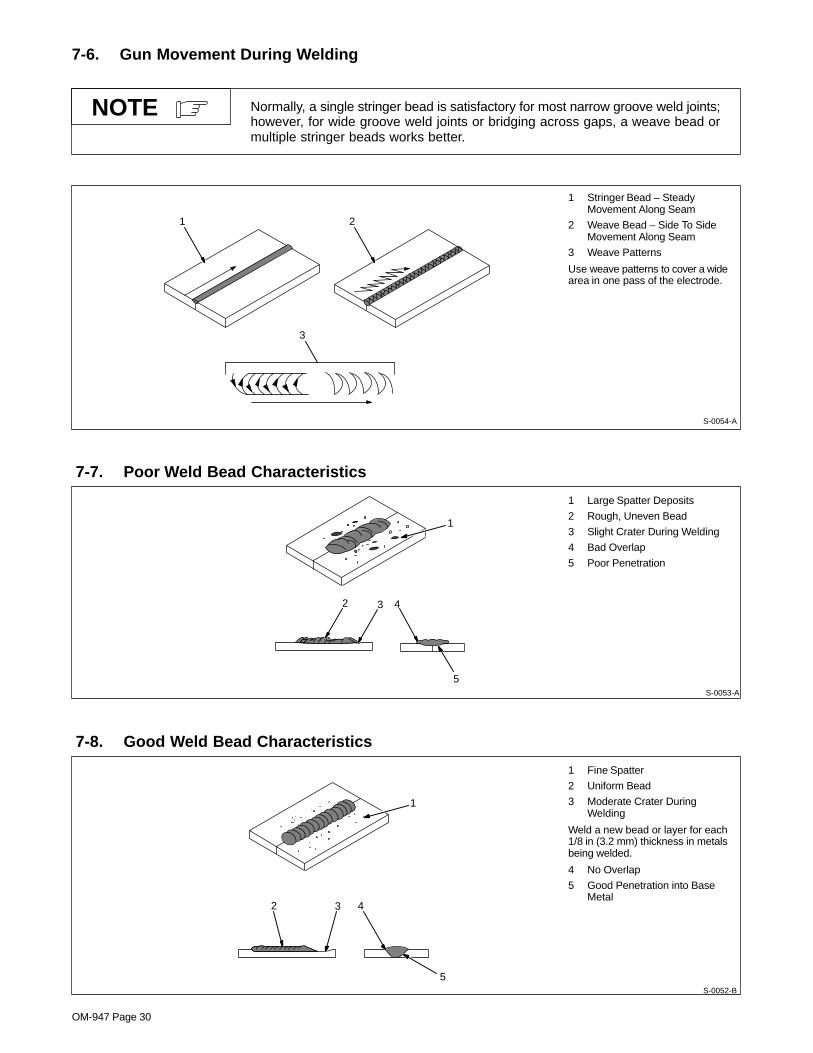
Normally, a single stringer bead is satisfactory for most narrow groove weld joints;however, for wide groove weld joints or bridging across gaps, a weave bead ormultiple stringer beads works better.
NOTE
1 Stringer Bead – SteadyMovement Along Seam
2 Weave Bead – Side To SideMovement Along Seam
3 Weave Patterns
Use weave patterns to cover a widearea in one pass of the electrode.
S-0054-A
3
1 2
7-7. Poor Weld Bead Characteristics
1 Large Spatter Deposits
2 Rough, Uneven Bead
3 Slight Crater During Welding
4 Bad Overlap
5 Poor Penetration
5
42 3
1
S-0053-A
7-8. Good Weld Bead Characteristics
1 Fine Spatter
2 Uniform Bead
3 Moderate Crater DuringWelding
Weld a new bead or layer for each1/8 in (3.2 mm) thickness in metalsbeing welded.
4 No Overlap
5 Good Penetration into BaseMetal
S-0052-B
2 3
1
4
5

OM-947 Page 31
7-9. Troubleshooting – Excessive Spatter
Excessive Spatter – scattering of molten metal particles thatcool to solid form near weld bead.
S-0636
Possible Causes Corrective Actions
Wire feed speed too high. Select lower wire feed speed.
Voltage too high. Select lower voltage range.
Electrode extension (stickout) too long. Use shorter electrode extension (stickout).
Workpiece dirty. Remove all grease, oil, moisture, rust, paint, undercoating, and dirt from work surface before welding.
Insufficient shielding gas at welding arc. Increase flow of shielding gas at regulator/flowmeter and/or prevent drafts near welding arc.
Dirty welding wire. Use clean, dry welding wire.
Eliminate pickup of oil or lubricant on welding wire from feeder or liner.
7-10. Troubleshooting – Porosity
Porosity – small cavities or holes resulting from gas pocketsin weld metal.
S-0635
Possible Causes Corrective Actions
Insufficient shielding gas at welding arc. Increase flow of shielding gas at regulator/flowmeter and/or prevent drafts near welding arc.
Remove spatter from gun nozzle.
Check gas hoses for leaks.
Place nozzle 1/4 to 1/2 in (6-13 mm) from workpiece.
Hold gun near bead at end of weld until molten metal solidifies.
Wrong gas. Use welding grade shielding gas; change to different gas.
Dirty welding wire. Use clean, dry welding wire.
Eliminate pick up of oil or lubricant on welding wire from feeder or liner.
Workpiece dirty. Remove all grease, oil, moisture, rust, paint, coatings, and dirt from work surface before welding.
Use a more highly deoxidizing welding wire (contact supplier).
Welding wire extends too far out of nozzle. Be sure welding wire extends not more than 1/2 in (13 mm) beyond nozzle.
7-11. Troubleshooting – Excessive Penetration
Good Penetration
Excessive Penetration – weld metal melting through base metaland hanging underneath weld.
Excessive PenetrationS-0639
Possible Causes Corrective Actions
Excessive heat input. Select lower voltage range and reduce wire feed speed.
Increase travel speed.

OM-947 Page 32
7-12. Troubleshooting – Lack Of Penetration
Lack Of Penetration – shallowfusion between weld metal andbase metal.
Lack of Penetration Good PenetrationS-0638
Possible Causes Corrective Actions
Improper joint preparation. Material too thick. Joint preparation and design must provide access to bottom of groove whilemaintaining proper welding wire extension and arc characteristics.
Improper weld technique. Maintain normal gun angle of 0 to 15 degrees to achieve maximum penetration.
Keep arc on leading edge of weld puddle.
Be sure welding wire extends not more than 1/2 in (13 mm) beyond nozzle.
Insufficient heat input. Select higher wire feed speed and/or select higher voltage range.
Reduce travel speed.
7-13. Troubleshooting – Incomplete Fusion
Incomplete Fusion – failure of weld metal to fuse completely withbase metal or a preceeding weld bead.
S-0637
Possible Causes Corrective Actions
Workpiece dirty. Remove all grease, oil, moisture, rust, paint, undercoating, and dirt from work surface beforewelding.
Insufficient heat input. Select higher voltage range and/or adjust wire feed speed.
Improper welding technique. Place stringer bead in proper location(s) at joint during welding.
Adjust work angle or widen groove to access bottom during welding.
Momentarily hold arc on groove side walls when using weaving technique.
Keep arc on leading edge of weld puddle.
Use correct gun angle of 0 to 15 degrees.
7-14. Troubleshooting – Burn-Through
Burn-Through – weld metal melting completely through base metalresulting in holes where no metal remains.
S-0640
Possible Causes Corrective Actions
Excessive heat input. Select lower voltage range and reduce wire feed speed.
Increase and/or maintain steady travel speed.

OM-947 Page 33
7-15. Troubleshooting – Waviness Of Bead
Waviness Of Bead – weld metal that is not parallel and does not coverjoint formed by base metal.
S-0641
Possible Causes Corrective Actions
Welding wire extends too far out of nozzle. Be sure welding wire extends not more than 1/2 in (13 mm) beyond nozzle.
Unsteady hand. Support hand on solid surface or use two hands.
7-16. Troubleshooting – Distortion
Distortion – contraction of weld metal during welding that forcesbase metal to move.
Base metal movesin the direction of
the weld bead.S-0642
Possible Causes Corrective Actions
Excessive heat input. Use restraint (clamp) to hold base metal in position.
Make tack welds along joint before starting welding operation.
Select lower voltage range and/or reduce wire feed speed.
Increase travel speed.
Weld in small segments and allow cooling between welds.
7-17. Troubleshooting Guide For Semiautomatic Welding Equipment
Problem Probable Cause Remedy
Wire feed motor operates, butwire does not feed.
Too little pressure on wire feed rolls. Increase pressure setting on wire feed rolls.wire does not feed.
Incorrect wire feed rolls. Check size stamped on wire feed rolls, replace to matchwire size and type if necessary.
Wire spool brake pressure too high. Decrease brake pressure on wire spool.
Restriction in the gun and/or assembly. Check and replace cable, gun, tip adapter, and contacttip if damaged. Check size of contact tip and cable liner,replace if necessary.
Wire curling up in front of thewire feed rolls (bird nesting).
Too much pressure on wire feed rolls. Decrease pressure setting on wire feed rolls.wire feed rolls (bird nesting).
Incorrect cable liner or gun contact tip size. Check size of contact tip and check cable liner lengthand diameter, replace if necessary.
Gun end not inserted into drive housing properly. Loosen gun securing bolt in drive housing and push gunend into housing just enough so it does not touch wirefeed rolls.
Dirty or damaged (kinked) liner. Replace liner.
Welding arc not stable. Wire slipping in drive rolls. Adjust pressure setting on wire feed rolls. Replace worndrive rolls if necessary.
Wrong size gun liner or contact tip. Match liner and contact tip to wire size and type.
Incorrect voltage setting for selected wire feed speed onwelding power source.
Readjust welding parameters.
Loose connections at the gun weld cable or work cable. Check and tighten all connections.
Gun in poor shape or loose connection inside gun. Repair or replace gun as necessary.

OM-947 Page 34
SECTION 8 – PARTS LIST
� Hardware is common andnot available unless listed.
803 446-A
1
23
4
5
6
6
7
8
9
10
11
12
13
14
15
16
17
18
19
42
20
21 22
23 24
25
26
27
28
29
3230
31
33
34
35
36
37
3839
40
41
Figure 9-1. Main Assembly

OM-947 Page 35
DescriptionPartNo.
Dia.Mkgs.
ItemNo.
Figure 9-1. Main Assembly
Quantity
1 210 432 CASE SECTION, front/bottom/rear 1. . . . . . . . . . . . . . . . . . . . . . . . . . . . . . . . . . . . . . . . . . . . . . . . . . . . 210 530 BLANK, snap-in 1. . . . . . . . . . . . . . . . . . . . . . . . . . . . . . . . . . . . . . . . . . . . . . . . . . . . . . . . . . . . . . . . . . . . . . . .
2 210 433 BAFFLE, center 1. . . . . . . . . . . . . . . . . . . . . . . . . . . . . . . . . . . . . . . . . . . . . . . . . . . . . . . . . . . . . . . . . . . . 3 +210 434 WRAPPER, cover 1. . . . . . . . . . . . . . . . . . . . . . . . . . . . . . . . . . . . . . . . . . . . . . . . . . . . . . . . . . . . . . . . . . 4 210 435 DOOR, access 1. . . . . . . . . . . . . . . . . . . . . . . . . . . . . . . . . . . . . . . . . . . . . . . . . . . . . . . . . . . . . . . . . . . . . 5 211 095 BEZEL, front 1. . . . . . . . . . . . . . . . . . . . . . . . . . . . . . . . . . . . . . . . . . . . . . . . . . . . . . . . . . . . . . . . . . . . . . . 6 196 006 HINGE, door access 2. . . . . . . . . . . . . . . . . . . . . . . . . . . . . . . . . . . . . . . . . . . . . . . . . . . . . . . . . . . . . . . . . 7 207 587 CIRCUIT CARD ASSY, control 1. . . . . . . . . . . . . . . . . . . . . . . . . . . . . . . . . . . . . . . . . . . . . . . . . . . . . . . . 8 134 201 STANDOFF 6. . . . . . . . . . . . . . . . . . . . . . . . . . . . . . . . . . . . . . . . . . . . . . . . . . . . . . . . . . . . . . . . . . . . . . . . 9 209 356 RECTIFIER, assy 1. . . . . . . . . . . . . . . . . . . . . . . . . . . . . . . . . . . . . . . . . . . . . . . . . . . . . . . . . . . . . . . . . . .
10 209 392 BUS BAR, output positive 1. . . . . . . . . . . . . . . . . . . . . . . . . . . . . . . . . . . . . . . . . . . . . . . . . . . . . . . . . . . . 11 193 194 BUS BAR, output negative 1. . . . . . . . . . . . . . . . . . . . . . . . . . . . . . . . . . . . . . . . . . . . . . . . . . . . . . . . . . . 12 210 109 CIRCUIT BREAKER, 25A 1. . . . . . . . . . . . . . . . . . . . . . . . . . . . . . . . . . . . . . . . . . . . . . . . . . . . . . . . . . . . 13 111 443 BUSHING, strain relief 1. . . . . . . . . . . . . . . . . . . . . . . . . . . . . . . . . . . . . . . . . . . . . . . . . . . . . . . . . . . . . . . 14 147 545 CORD SET 1. . . . . . . . . . . . . . . . . . . . . . . . . . . . . . . . . . . . . . . . . . . . . . . . . . . . . . . . . . . . . . . . . . . . . . . . 15 208 015 HANDLE 1. . . . . . . . . . . . . . . . . . . . . . . . . . . . . . . . . . . . . . . . . . . . . . . . . . . . . . . . . . . . . . . . . . . . . . . . . . . 16 209 467 MOTOR, fan 115VAC 1. . . . . . . . . . . . . . . . . . . . . . . . . . . . . . . . . . . . . . . . . . . . . . . . . . . . . . . . . . . . . . . . 17 210 413 BLADE, fan 1. . . . . . . . . . . . . . . . . . . . . . . . . . . . . . . . . . . . . . . . . . . . . . . . . . . . . . . . . . . . . . . . . . . . . . . . 18 209 213 TRANSFORMER 1. . . . . . . . . . . . . . . . . . . . . . . . . . . . . . . . . . . . . . . . . . . . . . . . . . . . . . . . . . . . . . . . . . . 19 203 868 STABILIZER 1. . . . . . . . . . . . . . . . . . . . . . . . . . . . . . . . . . . . . . . . . . . . . . . . . . . . . . . . . . . . . . . . . . . . . . . 20 196 575 SWITCH, rocker spst 1. . . . . . . . . . . . . . . . . . . . . . . . . . . . . . . . . . . . . . . . . . . . . . . . . . . . . . . . . . . . . . . . 21 209 873 POTENTIOMETER 1. . . . . . . . . . . . . . . . . . . . . . . . . . . . . . . . . . . . . . . . . . . . . . . . . . . . . . . . . . . . . . . . . 22 409 477 SWITCH, rotary 1. . . . . . . . . . . . . . . . . . . . . . . . . . . . . . . . . . . . . . . . . . . . . . . . . . . . . . . . . . . . . . . . . . . . . 23 211 338 KNOB, pointer 1. . . . . . . . . . . . . . . . . . . . . . . . . . . . . . . . . . . . . . . . . . . . . . . . . . . . . . . . . . . . . . . . . . . . . . 24 207 079 KNOB, pointer 1. . . . . . . . . . . . . . . . . . . . . . . . . . . . . . . . . . . . . . . . . . . . . . . . . . . . . . . . . . . . . . . . . . . . . . 25 210 398 BUSHING, snap-in 1. . . . . . . . . . . . . . . . . . . . . . . . . . . . . . . . . . . . . . . . . . . . . . . . . . . . . . . . . . . . . . . . . . 26 209 412 BUSHING, snap-in .500 dia 2. . . . . . . . . . . . . . . . . . . . . . . . . . . . . . . . . . . . . . . . . . . . . . . . . . . . . . . . . . 27 209 532 DRIVE, assy wire 1. . . . . . . . . . . . . . . . . . . . . . . . . . . . . . . . . . . . . . . . . . . . . . . . . . . . . . . . . . . . . . . . . . . 28 193 144 INSULATOR, output stud 1. . . . . . . . . . . . . . . . . . . . . . . . . . . . . . . . . . . . . . . . . . . . . . . . . . . . . . . . . . . . 29 202 726 ADAPTER, spool hub 1. . . . . . . . . . . . . . . . . . . . . . . . . . . . . . . . . . . . . . . . . . . . . . . . . . . . . . . . . . . . . . . . 30 202 998 SPRING, cprsn 1. . . . . . . . . . . . . . . . . . . . . . . . . . . . . . . . . . . . . . . . . . . . . . . . . . . . . . . . . . . . . . . . . . . . . 31 204 608 NUT 1. . . . . . . . . . . . . . . . . . . . . . . . . . . . . . . . . . . . . . . . . . . . . . . . . . . . . . . . . . . . . . . . . . . . . . . . . . . . . . . 32 203 072 WASHER 1. . . . . . . . . . . . . . . . . . . . . . . . . . . . . . . . . . . . . . . . . . . . . . . . . . . . . . . . . . . . . . . . . . . . . . . . . . 33 208 877 WELDING GUN 1. . . . . . . . . . . . . . . . . . . . . . . . . . . . . . . . . . . . . . . . . . . . . . . . . . . . . . . . . . . . . . . . . . . . 34 210 428 LABEL, door chart 1. . . . . . . . . . . . . . . . . . . . . . . . . . . . . . . . . . . . . . . . . . . . . . . . . . . . . . . . . . . . . . . . . . 35 204 036 LABEL, warning 1. . . . . . . . . . . . . . . . . . . . . . . . . . . . . . . . . . . . . . . . . . . . . . . . . . . . . . . . . . . . . . . . . . . . 36 208 820 CLAMP, work 1. . . . . . . . . . . . . . . . . . . . . . . . . . . . . . . . . . . . . . . . . . . . . . . . . . . . . . . . . . . . . . . . . . . . . . . 37 196 619 CABLE, work 1. . . . . . . . . . . . . . . . . . . . . . . . . . . . . . . . . . . . . . . . . . . . . . . . . . . . . . . . . . . . . . . . . . . . . . . 38 ♦209 905 ADAPTER, gas hose 1. . . . . . . . . . . . . . . . . . . . . . . . . . . . . . . . . . . . . . . . . . . . . . . . . . . . . . . . . . . . . . 39 ♦209 907 TUBING, PVC 1. . . . . . . . . . . . . . . . . . . . . . . . . . . . . . . . . . . . . . . . . . . . . . . . . . . . . . . . . . . . . . . . . . . . 40 ♦116 996 VALVE, 115vac 1. . . . . . . . . . . . . . . . . . . . . . . . . . . . . . . . . . . . . . . . . . . . . . . . . . . . . . . . . . . . . . . . . . . 41 ♦197 198 CABLE TIE 2. . . . . . . . . . . . . . . . . . . . . . . . . . . . . . . . . . . . . . . . . . . . . . . . . . . . . . . . . . . . . . . . . . . . . . 42 ♦605 227 NUT, 750–14 Knurled 1. . . . . . . . . . . . . . . . . . . . . . . . . . . . . . . . . . . . . . . . . . . . . . . . . . . . . . . . . . . . . .
+When ordering a component originally displaying a precautionary label, the label should also be ordered.♦OPTIONALTo maintain the factory original performance of your equipment, use only Manufacturer’s SuggestedReplacement Parts. Model and serial number required when ordering parts from your local distributor.
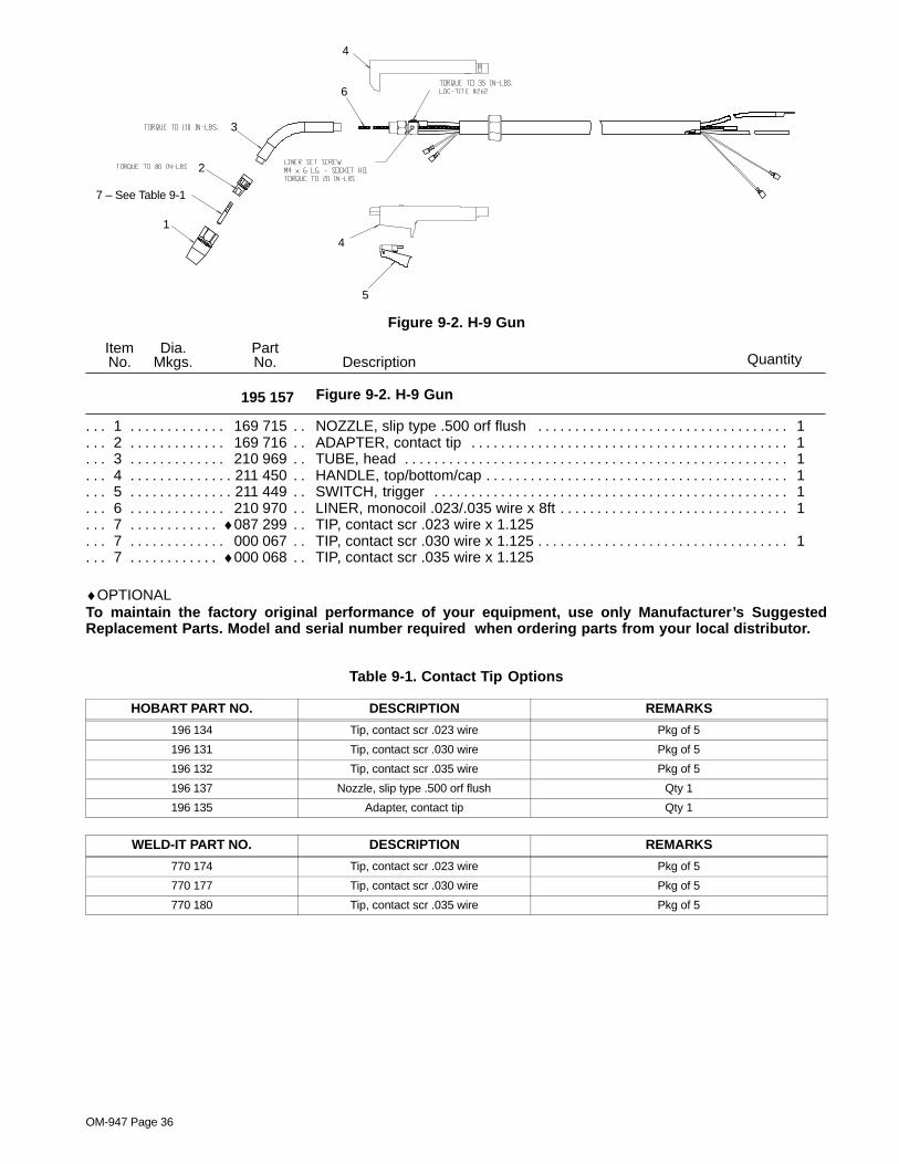
OM-947 Page 36
1
2
3
4
5
6
4
7 – See Table 9-1
Figure 9-2. H-9 Gun
QuantityDescriptionPartNo.
Dia.Mkgs.
ItemNo.
Figure 9-2. H-9 Gun195 157
1 169 715 NOZZLE, slip type .500 orf flush 1. . . . . . . . . . . . . . . . . . . . . . . . . . . . . . . . . . . . . . . . . . . . . . . . . . . . 2 169 716 ADAPTER, contact tip 1. . . . . . . . . . . . . . . . . . . . . . . . . . . . . . . . . . . . . . . . . . . . . . . . . . . . . . . . . . . . . 3 210 969 TUBE, head 1. . . . . . . . . . . . . . . . . . . . . . . . . . . . . . . . . . . . . . . . . . . . . . . . . . . . . . . . . . . . . . . . . . . . . . 4 211 450 HANDLE, top/bottom/cap 1. . . . . . . . . . . . . . . . . . . . . . . . . . . . . . . . . . . . . . . . . . . . . . . . . . . . . . . . . . . . 5 211 449 SWITCH, trigger 1. . . . . . . . . . . . . . . . . . . . . . . . . . . . . . . . . . . . . . . . . . . . . . . . . . . . . . . . . . . . . . . . . . . 6 210 970 LINER, monocoil .023/.035 wire x 8ft 1. . . . . . . . . . . . . . . . . . . . . . . . . . . . . . . . . . . . . . . . . . . . . . . . . 7 ♦087 299 TIP, contact scr .023 wire x 1.125. . . . . . . . . . . . . . . . . 7 000 067 TIP, contact scr .030 wire x 1.125 1. . . . . . . . . . . . . . . . . . . . . . . . . . . . . . . . . . . . . . . . . . . . . . . . . . . . 7 ♦000 068 TIP, contact scr .035 wire x 1.125. . . . . . . . . . . . . . . . .
♦OPTIONALTo maintain the factory original performance of your equipment, use only Manufacturer’s SuggestedReplacement Parts. Model and serial number required when ordering parts from your local distributor.
Table 9-1. Contact Tip Options
HOBART PART NO. DESCRIPTION REMARKS
196 134 Tip, contact scr .023 wire Pkg of 5
196 131 Tip, contact scr .030 wire Pkg of 5
196 132 Tip, contact scr .035 wire Pkg of 5
196 137 Nozzle, slip type .500 orf flush Qty 1
196 135 Adapter, contact tip Qty 1
WELD-IT PART NO. DESCRIPTION REMARKS
770 174 Tip, contact scr .023 wire Pkg of 5
770 177 Tip, contact scr .030 wire Pkg of 5
770 180 Tip, contact scr .035 wire Pkg of 5
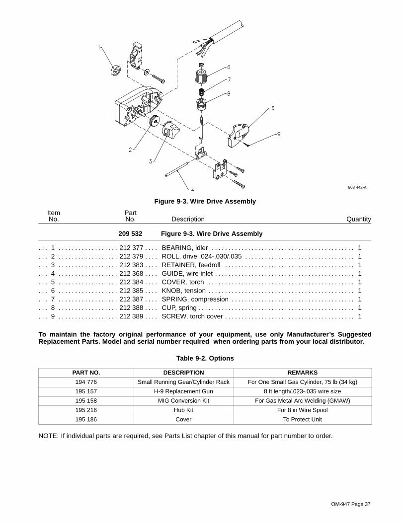
OM-947 Page 37
803 442-A
Figure 9-3. Wire Drive Assembly
QuantityDescriptionPartNo.
209 532
ItemNo.
Figure 9-3. Wire Drive Assembly
1 212 377 BEARING, idler 1. . . . . . . . . . . . . . . . . . . . . . . . . . . . . . . . . . . . . . . . . . . . . . . . . . . . . . . . . . . . . . . . . . . . 2 212 379 ROLL, drive .024-.030/.035 1. . . . . . . . . . . . . . . . . . . . . . . . . . . . . . . . . . . . . . . . . . . . . . . . . . . . . . . . . . 3 212 383 RETAINER, feedroll 1. . . . . . . . . . . . . . . . . . . . . . . . . . . . . . . . . . . . . . . . . . . . . . . . . . . . . . . . . . . . . . . . 4 212 368 GUIDE, wire inlet 1. . . . . . . . . . . . . . . . . . . . . . . . . . . . . . . . . . . . . . . . . . . . . . . . . . . . . . . . . . . . . . . . . . . 5 212 384 COVER, torch 1. . . . . . . . . . . . . . . . . . . . . . . . . . . . . . . . . . . . . . . . . . . . . . . . . . . . . . . . . . . . . . . . . . . . . 6 212 385 KNOB, tension 1. . . . . . . . . . . . . . . . . . . . . . . . . . . . . . . . . . . . . . . . . . . . . . . . . . . . . . . . . . . . . . . . . . . . . 7 212 387 SPRING, compression 1. . . . . . . . . . . . . . . . . . . . . . . . . . . . . . . . . . . . . . . . . . . . . . . . . . . . . . . . . . . . . . 8 212 388 CUP, spring 1. . . . . . . . . . . . . . . . . . . . . . . . . . . . . . . . . . . . . . . . . . . . . . . . . . . . . . . . . . . . . . . . . . . . . . . . 9 212 389 SCREW, torch cover 1. . . . . . . . . . . . . . . . . . . . . . . . . . . . . . . . . . . . . . . . . . . . . . . . . . . . . . . . . . . . . . . .
To maintain the factory original performance of your equipment, use only Manufacturer’s SuggestedReplacement Parts. Model and serial number required when ordering parts from your local distributor.
Table 9-2. Options
PART NO. DESCRIPTION REMARKS
194 776 Small Running Gear/Cylinder Rack For One Small Gas Cylinder, 75 lb (34 kg)
195 157 H-9 Replacement Gun 8 ft length/.023-.035 wire size
195 158 MIG Conversion Kit For Gas Metal Arc Welding (GMAW)
195 216 Hub Kit For 8 in Wire Spool
195 186 Cover To Protect Unit
NOTE: If individual parts are required, see Parts List chapter of this manual for part number to order.

Notes
Warranty Questions?
Call1-877-HOBART1for your localHobart distributor.
hobart retail 6/02
ServiceYou always get the fast,reliable response youneed. Most replacementparts can be in yourhands in 24 hours.
SupportNeed fast answers to thetough welding questions?Contact your distributor orcall 1-800-332-3281. Theexpertise of the distributorand Hobart is there tohelp you, every step ofthe way.
Effective January 1, 20025/3/1 WARRANTY applies to all Handler 135 and 175 models, Airforce 250, 250A, and 375 models,
and Champion 10,000 models.This warranty also applies to the Beta-Mig 1800, Champ 1435, 2060,8500 models, Ironman 250, Stickmate models, Tigmate models, and HSW-15 and HSW-25 spot
welder models effective with Serial No. KK200262 and newer.
This limited warranty supersedes all previous Hobart warranties and is exclusive withno other guarantees or warranties expressed or implied.
Hobart products are serviced by Hobart or Miller Authorized Service Agencies.
LIMITED WARRANTY – Subject to the terms and conditionsbelow, Hobart/Miller Electric Mfg. Co., Appleton, Wisconsin,warrants to its original retail purchaser that new Hobartequipment sold after the effective date of this limited warranty isfree of defects in material and workmanship at the time it isshipped by Hobart. THIS WARRANTY IS EXPRESSLY IN LIEUOF ALL OTHER WARRANTIES, EXPRESS OR IMPLIED,INCLUDING THE WARRANTIES OF MERCHANTABILITY ANDFITNESS.
Within the warranty periods listed below, Hobart/Miller will repairor replace any warranted parts or components that fail due tosuch defects in material or workmanship. Hobart/Miller must benotified in writing within thirty (30) days of such defect or failure, atwhich time Hobart/Miller will provide instructions on the warrantyclaim procedures to be followed.
Hobart/Miller shall honor warranty claims on warrantedequipment listed below in the event of such a failure within thewarranty time periods. All warranty time periods start on the datethat the equipment was delivered to the original retail purchaser,or one year after the equipment is sent to a North Americandistributor or eighteen months after the equipment is sent to anInternational distributor.
1. 5 Years — Parts and Labor
* Original Main Power Rectifiers
* Transformers
* Stabilizers
* Reactors
* Rotors, Stators and Brushes
2. 3 Years — Parts and Labor
* Drive Systems
* PC Boards
* Idle Module
* Solenoid Valves
* Switches and Controls
* Spot Welder Transformer
3. 1 Year — Parts and Labor Unless Specified(90 days for industrial use)
* Motor-Driven Guns
* MIG Guns/TIG Torches
* Relays
* Contactors
* Regulators
* Water Coolant Systems
* Flowgauge and Flowmeter Regulators (No Labor)* HF Units
* Running Gear/Trailers
* Plasma Cutting Torches
* Remote Controls
* Replacement Parts (No labor)
* Accessories
* Field Options(NOTE: Field options are covered for the remainingwarranty period of the product they are installed in, orfor a minimum of one year — whichever is greater.)
4. Engines, batteries and tires are warranted separately by themanufacturer.
Hobart’s 5/3/1 Limited Warranty shall not apply to:
1. Consumable components such as contact tips, cuttingnozzles, slip rings, drive rolls, gas diffusers, plasmatorch tips and electrodes, weld cables, and tongs andtips, or parts that fail due to normal wear.
2. Items furnished by Hobart/Miller, but manufactured byothers, such as engines or trade accessories. These itemsare covered by the manufacturer’s warranty, if any.
3. Equipment that has been modified by any party other thanHobart/Miller, or equipment that has been improperlyinstalled, improperly operated or misused based uponindustry standards, or equipment which has not hadreasonable and necessary maintenance, or equipmentwhich has been used for operation outside of thespecifications for the equipment.
HOBART PRODUCTS ARE INTENDED FOR PURCHASE ANDUSE BY COMMERCIAL/INDUSTRIAL USERS AND PERSONSTRAINED AND EXPERIENCED IN THE USE ANDMAINTENANCE OF WELDING EQUIPMENT.
In the event of a warranty claim covered by this warranty, theexclusive remedies shall be, at Hobart’s/Miller’s option: (1) repair;or (2) replacement; or, where authorized in writing byHobart/Miller in appropriate cases, (3) the reasonable cost ofrepair or replacement at an authorized Hobart/Miller servicestation; or (4) payment of or credit for the purchase price (lessreasonable depreciation based upon actual use) upon return ofthe goods at customer’s risk and expense. Hobart’s/Miller’soption of repair or replacement will be F.O.B., Factory atAppleton, Wisconsin, or F.O.B. at a Hobart/Miller authorizedservice facility as determined by Hobart/Miller. Therefore nocompensation or reimbursement for transportation costs of anykind will be allowed.
TO THE EXTENT PERMITTED BY LAW, THE REMEDIESPROVIDED HEREIN ARE THE SOLE AND EXCLUSIVEREMEDIES. IN NO EVENT SHALL HOBART/MILLER BELIABLE FOR DIRECT, INDIRECT, SPECIAL, INCIDENTAL ORCONSEQUENTIAL DAMAGES (INCLUDING LOSS OFPROFIT), WHETHER BASED ON CONTRACT, TORT OR ANYOTHER LEGAL THEORY.
ANY EXPRESS WARRANTY NOT PROVIDED HEREIN ANDANY IMPLIED WARRANTY, GUARANTY ORREPRESENTATION AS TO PERFORMANCE, AND ANYREMEDY FOR BREACH OF CONTRACT TORT OR ANYOTHER LEGAL THEORY WHICH, BUT FOR THIS PROVISION,MIGHT ARISE BY IMPLICATION, OPERATION OF LAW,CUSTOM OF TRADE OR COURSE OF DEALING, INCLUDINGANY IMPLIED WARRANTY OF MERCHANTABILITY ORFITNESS FOR PARTICULAR PURPOSE, WITH RESPECT TOANY AND ALL EQUIPMENT FURNISHED BYHOBART/MILLER IS EXCLUDED AND DISCLAIMED BYHobart/Miller.
Some states in the U.S.A. do not allow limitations of how long animplied warranty lasts, or the exclusion of incidental, indirect,special or consequential damages, so the above limitation orexclusion may not apply to you. This warranty provides specificlegal rights, and other rights may be available, but may vary fromstate to state.
In Canada, legislation in some provinces provides for certainadditional warranties or remedies other than as stated herein,and to the extent that they may not be waived, the limitations andexclusions set out above may not apply. This Limited Warrantyprovides specific legal rights, and other rights may be available,but may vary from province to province.

PRINTED IN USA 2002 Hobart Welding Products. 8/02
Hobart Welding ProductsAn Illinois Tool Works Company600 West Main StreetTroy, OH 45373 USA
For Technical Assistance:Call1-800-332-3281For Literature Or Nearest Dealer:Call 1-877-Hobart1
Model Name Serial/Style Number
Purchase Date (Date which equipment was delivered to original customer.)
Distributor
Address
City
State Zip
Please complete and retain with your personal records.
Always provide Model Name and Serial/Style Number.
To locate a Distributor,retail or service location:
Call 1-877-Hobart1 or visit our website atwww.HobartWelders.com
Contact your Distributor for:
Welding Supplies and Consumables
Options and Accessories
Personal Safety Equipment
Service and Repair
Replacement Parts
Training (Schools, Videos, Books)
Technical Manuals (Servicing Informationand Parts)
Circuit Diagrams
Welding Process Handbooks
Contact the Delivering Carrier to:
Resources Available
Owner’s Record
File a claim for loss or damage duringshipment.
For assistance in filing or settling claims, contactyour distributor and/or equipment manufacturer’sTransportation Department.
For technical assistance:
Call 1-800-332-3281


