11
Koldwater Technologies, LLC P.O. Box 701 Mannford, Oklahoma USA 74044-0701 http://www.koldwater.com Hands-On Experience with Live Circuits without the Risk ! SAMPLE

Koldwater Technologies, LLC P.O. Box 701
Mannford, Oklahoma USA 74044-0701
http://www.koldwater.com
Hands-On Experience with Live
Circuits without the Risk !
SAMPLE

3
Table of Contents
INTRODUCTION TO TROUBLESHOOTING .......................................................4
TROUBLESHOOTING CONTROL CIRCUITS.....................................................5
HOW TO USE THE TSTRAINER .........................................................................6
BASIC CIRCUITS PROBLEMS 1, 2 & 3 ..............................................................8
MOTOR CONTROL PROBLEMS 1, 2, 3, 4 & 5 ................................................13
PLCS PROBLEMS 1, 2, 3, 4, 5, 6, 7 & 8...........................................................20
APPENDIX .........................................................................................................32
SAMPLE

4
Introduction to Troubleshooting
Introduction: The skills of the competent technician must include a methodical means of troubleshooting and root cause analysis. This software package will introduce the trainee to a proven system of troubleshooting.
Terminal Objective: Upon completion the technician will display skills in methodical troubleshooting. This will be evidenced by successful completion of the increasingly complex troubleshooting simulations.
The TSTrainer Lab Manual
Published by Koldwater Technologies, LLC
SAMPLE
5
Troubleshooting Control Circuits Control circuits are generally designed so that an individual circuit controls only one function of a particular process or machine. This function may be the starting and stopping of a motor by the use of pushbuttons, the control of solenoid valves by limit switches or proximity switches or a variety of other operators. There are literally thousands of different types of control circuits, but the basic thing to remember is that generally, one circuit controls one machine function. When a motor fails or burns out, the first question ask of the maintenance technician is, “Why didn’t the motor starter protect this unit?” A motor starter that is properly installed and maintained should protect a motor against failure from burnout. When a problem does occur, is it due to an error in the use of the motor starter, due to poor maintenance or is it due to the inherent limitations of the starter. You may determine that the proper starter was installed with the correct overload heaters and the control circuit was in proper working order. Yet, the motor burned out for reasons that may be difficult or even impossible to determine. Newer starters may be ordered that provide special protective features including three overload trip elements, ambient- temperature compensation and phase monitoring systems that detect any unbalance in current and then automatically readjust the normal trip point. Regular maintenance is essential for magnetic starters. However, even the best maintenance practices cannot change the inherent design characteristics. There are some problems that are common to most magnetic motor starters. These problems are listed below;
Sudden bearing failures
Severe phase imbalance
Voltage surges
Improper calibration of overloads
Defective insulation
Rapid loading and unloading
Overvoltage
SAMPLE

6
How to use the TSTrainer
When a problem is selected, a screen depicting the layout of the system will appear. This screen will show all of the pertinent components and will react accordingly to the placement of the leads of the ‘virtual meter’. The next step
will be to open the ‘Work Order’ to obtain a report of the problem with the system. This ‘work order’ will only describe the symptoms noticed by the operator of the system. For you convenience, a description of the proper operation of the system may be obtained and printed by clicking on the link titled ‘Circuit Operation’.
SAMPLE

9
Basic Controls – Problem 1 The Work-Order states that nothing is working. This indicates that the logical place to begin troubleshooting is the power source of the system. A quick check of the circuit breaker will indicate the power is not turned off and the breaker is not tripped. Operating the ‘On’ and ‘Off’ buttons verify that neither light, nor the relay responds to their operation. At this point it is time to begin checking voltage at various points. Place the red meter lead on TP1 and the black meter lead on TP19. Record the voltage reading. (_______ VAC) If the voltage reading is equal to 120 VAC, then indications are that Line 1 is powered and voltage is available. If the voltage is not 120 VAC, indications are an open exist between the power source and the control cabinet. Move the black lead to TP2 and record the voltage reading (_______ VAC). If the reading is equal to 120 VAC, then Line 2 or the AC Neutral is available. If the voltage is not 120 VAC, this indicates there is an open between the power source and the control cabinet.
Remember, there is a root cause to this problem. The ‘quick may not completely solve the problem. It may reoccur at a later date. Observation and continued
SAMPLE
13
Motor Control Problems 1, 2, 3, 4 & 5
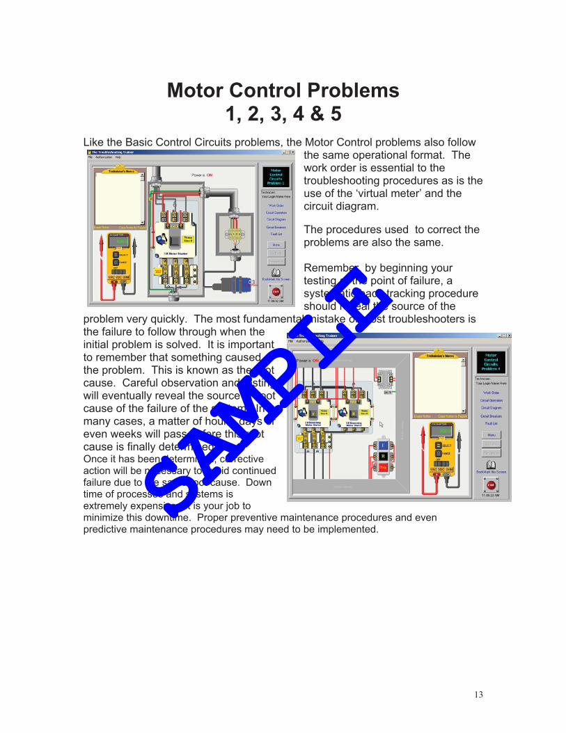
Like the Basic Control Circuits problems, the Motor Control problems also follow the same operational format. The work order is essential to the troubleshooting procedures as is the use of the ‘virtual meter’ and the circuit diagram.
The procedures used to correct the problems are also the same. Remember, by beginning your testing at the point of failure, a systematic back-tracking procedure should reveal the source of the
problem very quickly. The most fundamental mistake of most troubleshooters is the failure to follow through when the initial problem is solved. It is important to remember that something caused the problem. This is known as the root cause. Careful observation and testing will eventually reveal the source or root cause of the failure of the system. In many cases, a matter of hours, days or even weeks will pass before this root cause is finally determined. Once it has been determined, corrective action will be necessary to avoid continued failure due to the same root cause. Down time of processes and systems is extremely expensive. It is your job to minimize this downtime. Proper preventive maintenance procedures and even predictive maintenance procedures may need to be implemented. SAMPLE
20
PLCs Problems 1, 2, 3, 4, 5, 6, 7 & 8
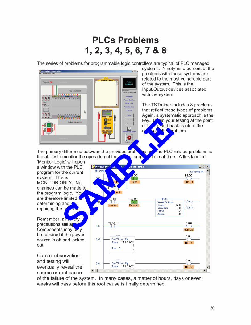
The series of problems for programmable logic controllers are typical of PLC managed
systems. Ninety-nine percent of the problems with these systems are related to the most vulnerable part of the system. This is the Input/Output devices associated with the system. The TSTrainer includes 8 problems that reflect these types of problems. Again, a systematic approach is the key. Begin your testing at the point of failure and back-track to the source of the problem.
The primary difference between the previous problems and the PLC related problems is the ability to monitor the operation of the control program in ‘real-time. A link labeled ‘Monitor Logic’ will open a window with the PLC program for the current system. This is MONITOR ONLY. No changes can be made to the program logic. You are therefore limited to determining and repairing the problem. Remember, all safety precautions still apply. Components may only be repaired if the power source is off and locked-out.
Careful observation and testing will eventually reveal the source or root cause of the failure of the system. In many cases, a matter of hours, days or even weeks will pass before this root cause is finally determined.
SAMPLE

21
Once it has been determined, corrective action will be necessary to avoid continued failure due to the same root cause. Down time of processes and systems is extremely expensive. It is your job to minimize this downtime. Proper preventive maintenance procedures and even predictive maintenance procedures may need to be implemented. All devices may be operated by ‘hand,’ making diagnosis of the problem much easier. The following screens are typical of those used in The TSTrainer.
S
AMPLE

29
SAMPLE

32
Appendix Learning institutions such as Community Colleges, Technical Schools and Apprenticeship programs, should consider building actual systems of their own design for troubleshooting training. While simulations through multimedia applications such as The TSTrainer are excellent for initial training in methodology, nothing can replace actual hands on practice. The circuits simulated in this software would be an excellent starting point for actual practice. Faulty components may be installed and interchanged at the discretion of the instructor. As an instructor, consider constructing actual circuits for reinforcement of the concepts learned here.
SAMPLE


