46
HANDS ON RELAY SCHOOL, MARCH 2018 SYNCHROPHASORS DEFINITIONS, FUNCTIONALITY AND STANDARDS Galina S. Antonova, Technical Sales Engineer

HANDS ON RELAY SCHOOL, MARCH 2018
SYNCHROPHASORS DEFINITIONS, FUNCTIONALITY AND STANDARDS Galina S. Ant onova , Technica l Sa les Eng ineer

Int roduct ion
Synchrop has or t echno log y
Synchrop has or d efinit ion
Synchrop has or t e rm ino log y
Synchrop has or s ys t em s
Phas or Meas urem ent Unit s (PMUs )
Synchrop has or s t and a rd s
Synchrop has or exercis es
Conclus ions
Slid e 2
Agenda

Hot summer blackout s
Slide 3

Sept ember 2011 Sout hwest US Out age
Source: NERC Recommendations from 2011 Southwest Outage May 8 2012 Slide 4
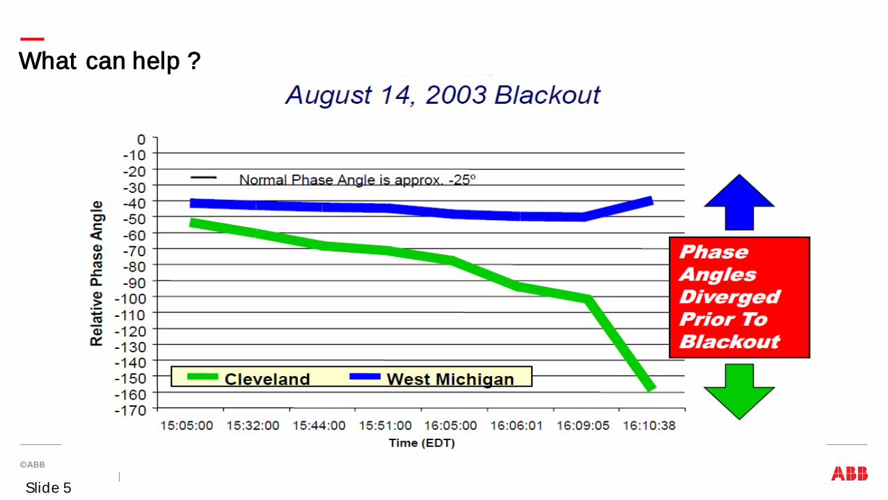
What can help ?
Slide 5

Power Syst ems Challenges and Solut ions
1) Int egrat ion of renewables Remot e grid operat ion wit h dist ribut ed generat ion (wind/ solar farms) Increase grid capacit y and st abilit y Balance load t o supply 2) Int egrat ion of elect ric vehicles Charging / billing Energy st orage Load management 3) Demand response Real t ime pricing / t arif fs Home aut omat ion / load management Dist ribut ed generat ion / st orage 4) Reliabilit y and ef f iciency cyber securit y cust omer out age informat ion emergency / peak power
2
2
3
3
4 4
4
Applicat ions and t echnologies Gat eways wit h bi-direct ional communicat ion for consumer int eract ion Smart met ers, Int ernet / mobile t elecom, smart houses Cust omer service syst ems including billing Fault det ect ion, isolat ion and rest orat ion; volt age opt imizat ion FACTS, HVDC, WAMS WAMPACS
1
1
1
1
Slid e 6
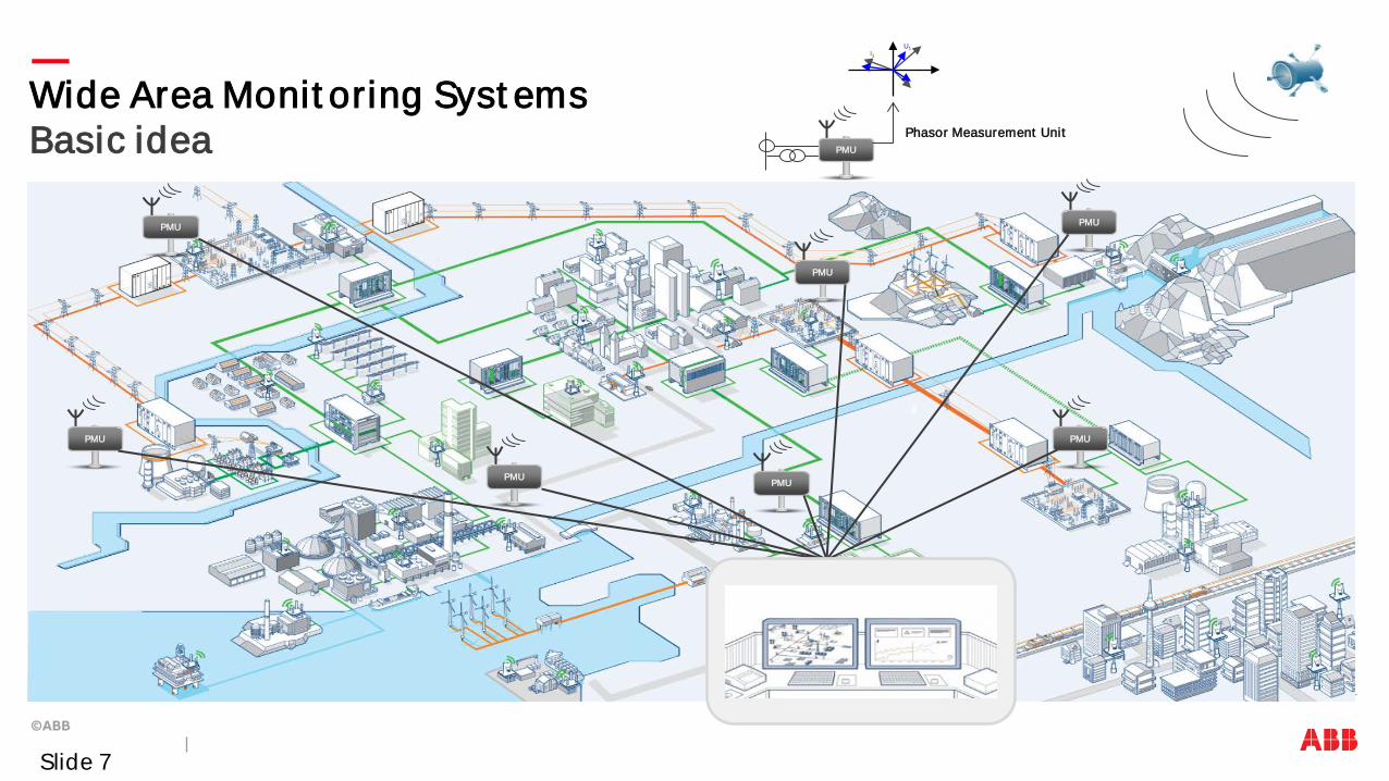
Wide Area Monit oring Syst ems Basic idea
PMU
PMU
PMU
PMU
PMU
PMU
PMU
PMU
Phasor Measurement Unit
U1 I3
Slide 7

Time stamps
GPS Satellite
Voltage and current phasors
Synchronization
Communication network
Wide-area Monit oring and Cont rol
System Protection Center
Slide 8

Wide Area Monit oring Syst ems Phasor measurement s
Timestamp accuracy: 1 microsecond Absolute angle accuracy error: < 0.1 degree CT/ VT: 0.2 …0.5%
High accuracy provides t he basis for an accurate monit oring of power networks
Slide 9

PMU measurement s vs SCADA/ EMS
Voltage phase angle What is new ?
Higher resolution
Faster response
Higher accuracy
How to use:
Supervision of dynamic phenomena
Closed-loop control
Model-calibration
Slide 10

Trad it iona l m eas urem ent s could viewed as X-Rays , while s ynchrop has ors a s an MRI s can !
X-Rays vs Mag net ic Res onance Im ag ing Tradit ional measurement s vs Synchrophasors
Slid e 11
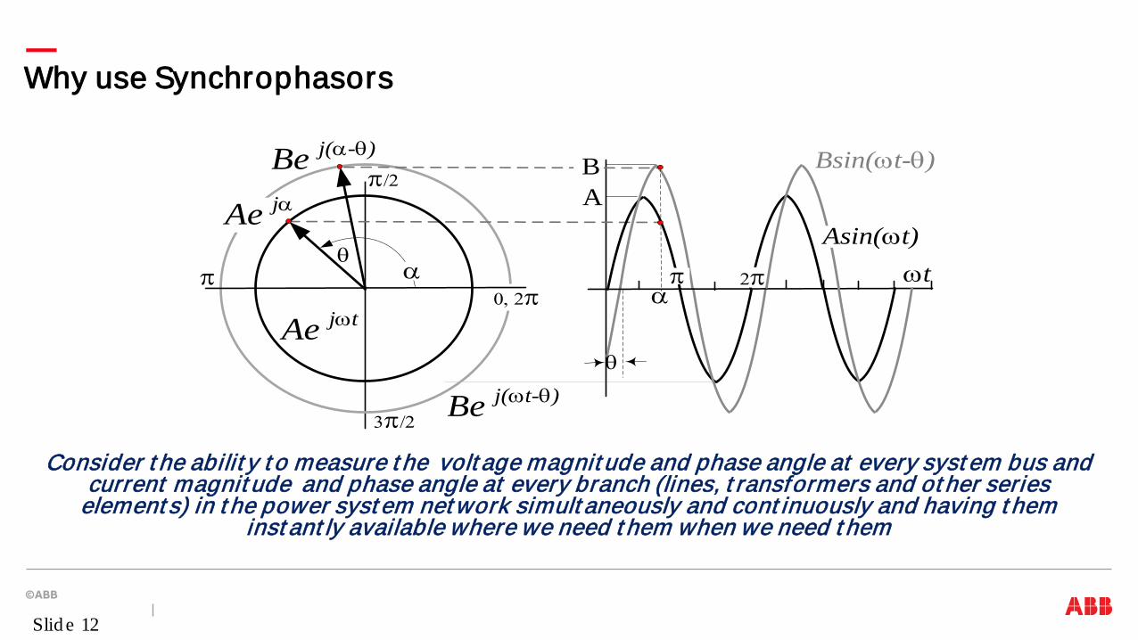
Why use Synchrophasors
Consider t he abilit y t o measure t he volt age magnit ude and phase angle at every syst em bus and current magnit ude and phase angle at every branch (lines, t ransformers and ot her series
element s) in t he power syst em net work simult aneously and cont inuously and having t hem inst ant ly available where we need t hem when we need t hem
Be j(ωt-θ)
Ae jωt
Be j(α-θ)
Ae jα
α
Bsin(ωt-θ)
π
π/2
3π/2
0, 2π
AB
θ
θ
α π 2π
Asin(ωt)ωt
Slid e 12

What is Phasor ?
.
A complex number t hat represent s t he phase and magnit ude of an AC waveform
Xm cos (2 π 60 t + φ) Xm/√2 ejφ
-1
-0.5
0
0.5
1
-50 0 50 100 150 200 250 300 350 400
φ φ
Xm
Xm/√2
Slid e 13

What is Phasor ?
A sinusoidal signal is complet ely represent ed by amplit ude, f requency, and phase angle. In many applicat ions t he f requency can be assumed f rozen and t he signal is represent ed by it s magnit ude and phase angle. The phasor is t his represent at ion. Anot her view is a periodic signal can be represent ed by a Fourier series wit h an inf init e number of t erms. Each t erm is a sinusoidal harmonic of t he fundament al wit h a complex coef f icient . Pract ical signals can be represent ed by a f init e number of t erms. In some cases we are int erest ed in only a part icular component . Here phasor measurement is only int erest ed in t he fundament al component which uses a 60 Hz (or 50 Hz) fundament al. This coef f icient is a complex number represent ing bot h magnit ude and phase angle of t he fundament al signal.
Slide 14
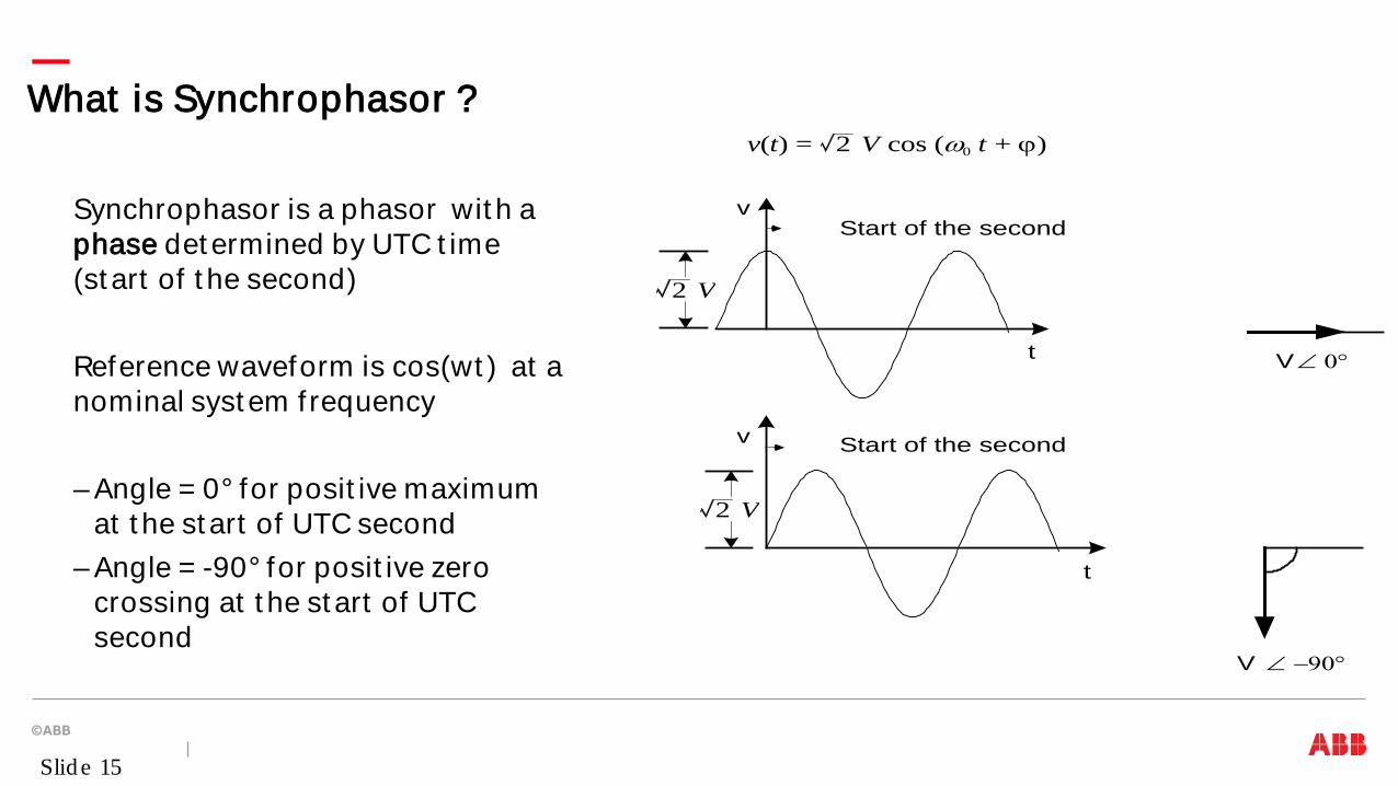
What is Synchrophasor ?
Synchrophasor is a phasor wit h a phase det ermined by UTC t ime (st art of t he second) Reference waveform is cos(wt ) at a nominal syst em f requency – Angle = 0° for posit ive maximum
at t he st art of UTC second – Angle = -90° for posit ive zero
crossing at t he st art of UTC second
V ∠ 0°
V ∠ −90°
Start of the second
Start of the second
t
t
v
v
2 V
2 V
v(t) = 2 V cos (ω0 t + ϕ)
Slid e 15

Synchrophasor def init ion
Ae j0
Acos(ωt)
Acos(ωt – π/2)
−π/2π/2
π0
−π/2π/2
π0
−π/2π/2
0
π/2π
0−π/2
π/2π
0−π/2
π/20
π
−π/2
Im
Re
Ae -jπ/2π
−π/2
Im
Re
(a) f(t) = Acos(ωt), θ = 0° (b) f(t) = Acos(ωt -π/2),θ = -π/2 (-90°)
Time Source Reference
New Second Pulse
π/2 π/2
Slide 16
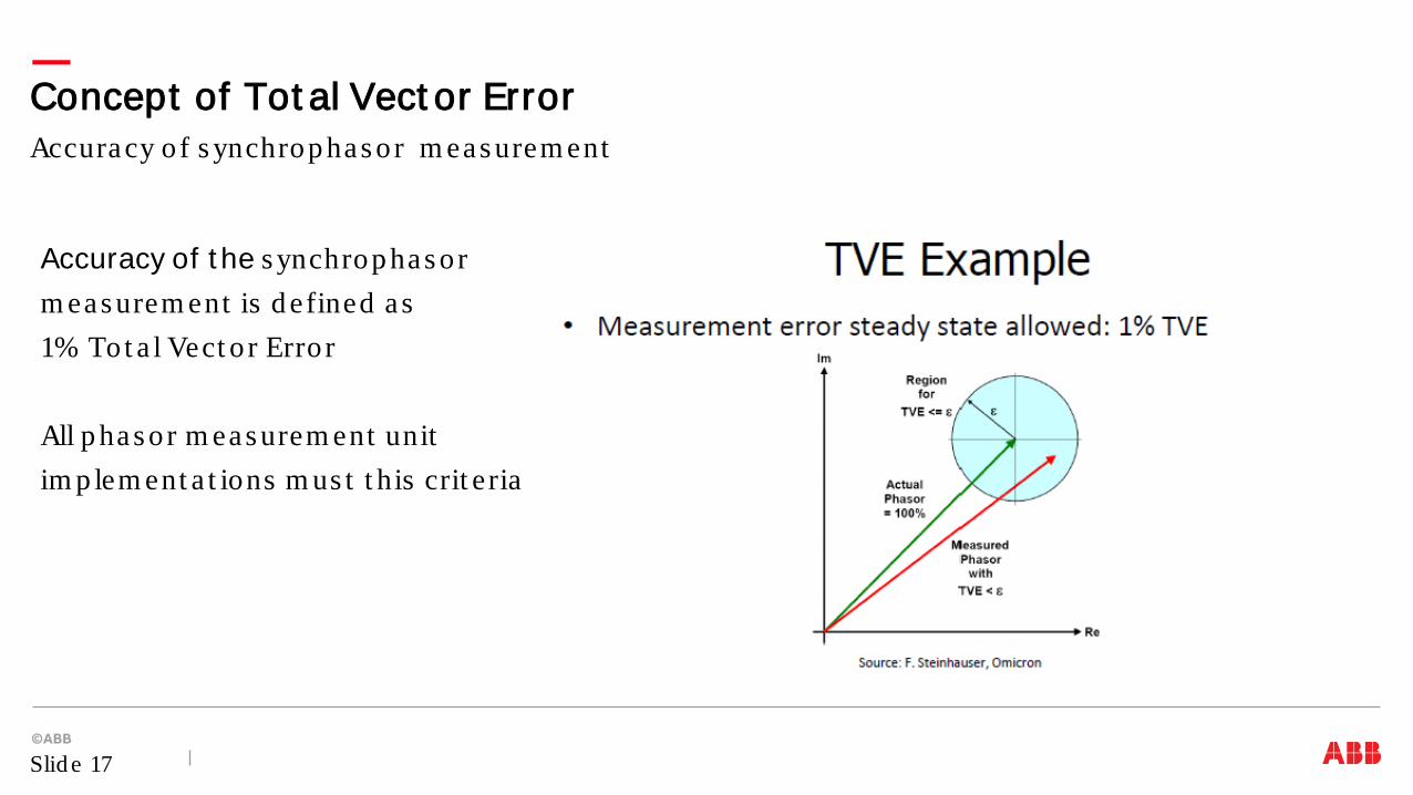
Accuracy of t he s ynchrop has or m eas urem ent is d efined a s 1% Tot a l Vect o r Erro r All p has or m eas urem ent unit im p lem ent a t ions m us t t his crit e ria
Accuracy o f s ynchrop has or m eas urem ent Concept of Tot al Vect or Error
Slid e 17

Synchrophasor implement at ion
Slide 18

Synchrophasors Terminology
UTC - Universal Time Coordinat ed GPS – Global Posit ioning Syst em wit h t ime t raceable t o UTC PMU – Phasor Measurement Unit
• Measures bus volt ages and line current s • Est imat es phasors • Synchronizes each phasor wit h UTC t ime – 1.0 ms accuracy • Sends synchrophasor dat a at 240, 120, 60, 30 f rames/ s t o client s, PDC, et c
PDC – Phasor Dat a Concent rat or
• Merges, synchronizes and archives synchrophasor dat a
Slide 19

Synchrophasor Measurement Syst em
APPLICATIONS . . . data display and real t ime cont rol act ions
Power Syst em
PDC/Server PDC/Server
ETHERNET
St ream ing s ynchrop has or d a t a on t he ne t work t o t he PDC fo r a rchiving . . .
GPS Sa t e llit e Tim e Synchroniza t ion
PMU
PMU PMU PMU
PMU
Slid e 20

Synchrophasor d a t a is t rans m it t ed in a s t and a rd fo rm a t Rep ort ing ra t e va ries from 10 t o 240 fram es p er s econd Num b er o f p has ors , ana log and d ig it a l s ig na ls is config urab le Tim es t am p , PMU Id , Freq uency, Ra t e o f chang e o f freq uency, and m is c Trig g ers a re t rans m it t ed
Synchrophasor Dat a f ormat
Slid e 21
first transmitted
last transmitted . . .
4 2
2
MSB LSB
DATA 1
FRAMESIZE SOC SYNC 2
DATA 2 DATA N CHK
IDCODE 2
FRACSEC 4
Various communicat ion int erfaces and prot ocols can be used Seria l RS232 int erface is s t ill s up p ort ed wit h up t o 60 fram es p er s econd Et hernet int erface is m os t com m on, e lect rica l o r op t ica l Et hernet (RJ45, LC, ST connect o rs ) Pro t ocols s up p ort ed a re TCP and UDP over IP Different p ro t ocols can b e us ed fo r s end ing Com m and s and Da t a
• Com m and s a re t yp ica lly s ent over TCP, a s it is m ore re liab le) • Dat a can b e s ent over TCP or UDP
UDP t rans m is s ions have an ad vant ag e o f one t o m any m od e, ca lled m ult icas t
Synchrophasor Communicat ion opt ions
Slid e 22

Synchrophasor communicat ion example
Slide 23

Time synchronizat ion opt ions GPS t ime synchronizat ion
1us t ime accuracy t o UTC Embedded GPS receiver, or ext ernal clock GPS cable (20m, 40m)
Elect rical IRIG-B int erface BNC cable 1 kHz Amplit ude Modulat ed or DC shif t
Opt ical IRIG-B int erface Opt ical cable, wit h ST connect or Immune t o surrounding noises
Emerging Precision Time Prot ocol IEEE 1588 / C37.238 st andards Et hernet , wit h 1us t ime accuracy t o source
Slide 24

Wide Area Monit oring Syst ems PSGuard and RES670
Slide 25
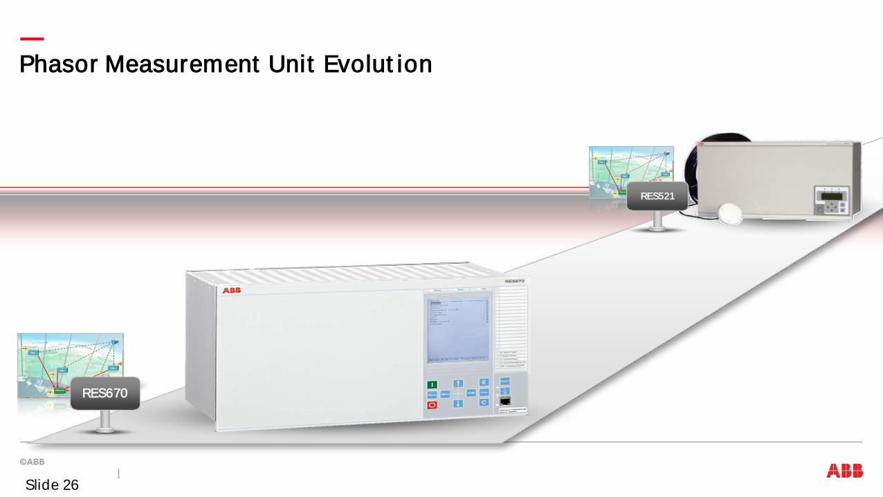
Phasor Measurement Unit Evolut ion
RES670
RES521
Slide 26

Synchrophasor Funct ionalit y Evolut ion
As PMU benef it s are furt her recognized, number of synchrophasor st reams and dat a st reamed has expanded dramat ically, for example • 32 phasors of dif ferent t ypes (single phase, all sequence component s) • 24 analogs (general (P,Q) and applicat ion-specif ic, e .g . SSO freq uencies , m ag nit ud es ) • 28 b ina ries (g enera l s t a t us and applicat ion-specif ic, e .g . SSO a la rm s / t rip p ing )
Slid e 27
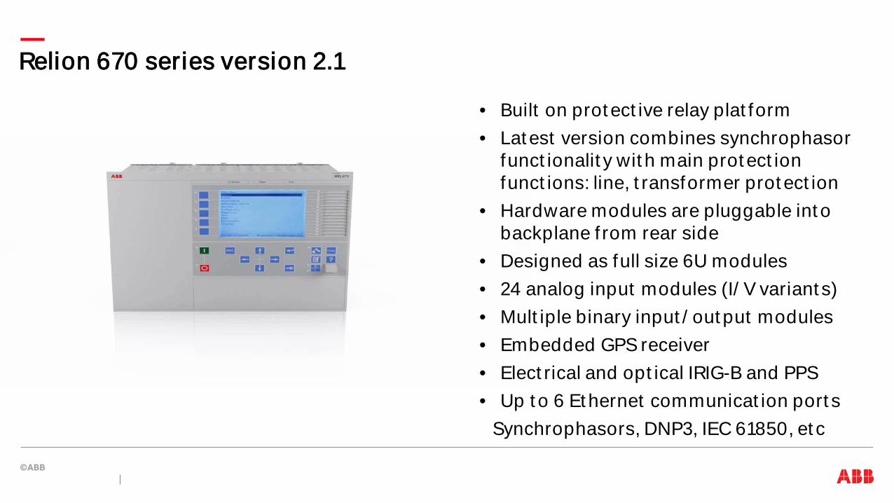
Relion 670 series version 2.1
• Built on prot ect ive relay plat form • Lat est version combines synchrophasor
funct ionalit y wit h main prot ect ion funct ions: line, t ransformer prot ect ion
• Hardware modules are pluggable int o backplane f rom rear side
• Designed as full size 6U modules • 24 analog input modules (I/ V variant s) • Mult iple binary input / out put modules • Embedded GPS receiver • Elect rical and opt ical IRIG-B and PPS • Up t o 6 Et hernet communicat ion port s
Synchrophasors, DNP3, IEC 61850, et c
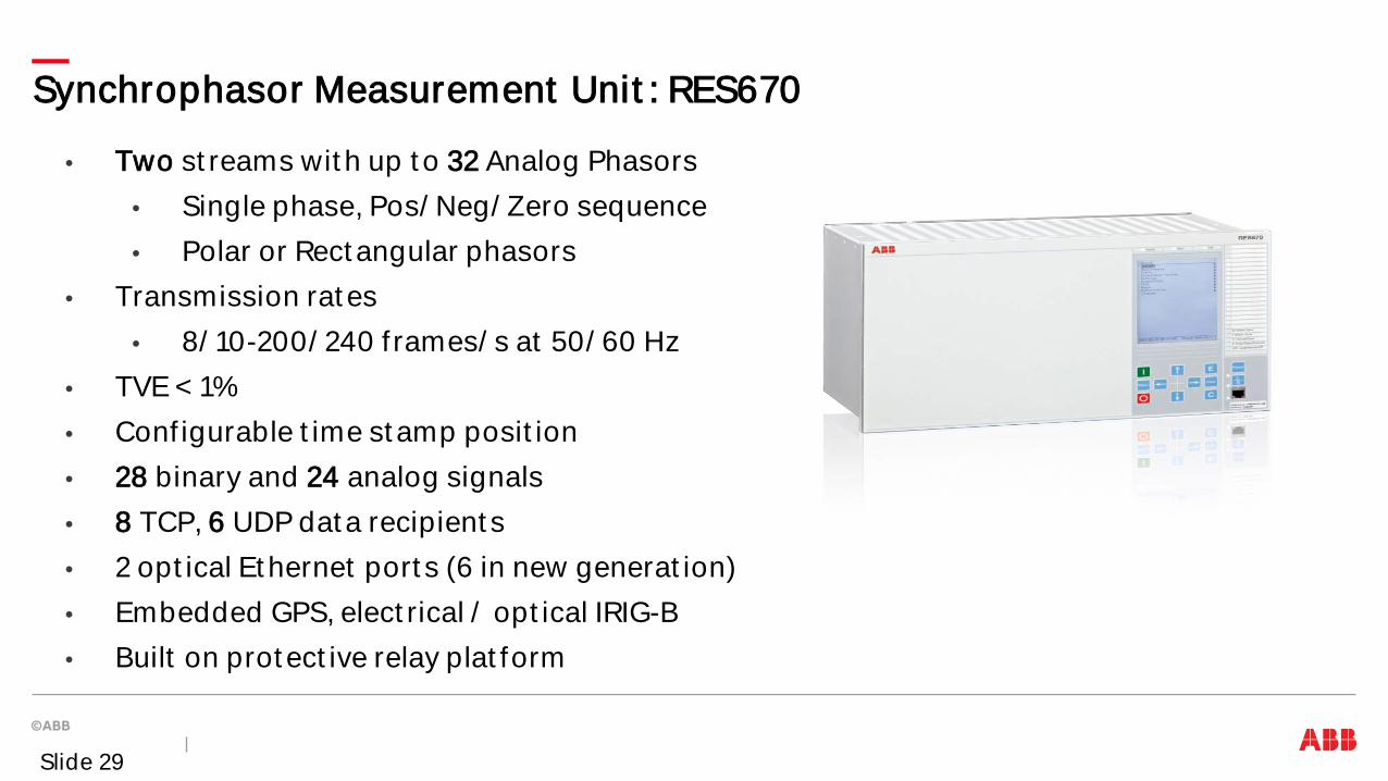
• Two st reams wit h up t o 32 Analog Phasors • Single phase, Pos/ Neg/ Zero sequence • Polar or Rect angular phasors
• Transmission rat es • 8/ 10-200/ 240 f rames/ s at 50/ 60 Hz
• TVE < 1% • Conf igurable t ime st amp posit ion • 28 binary and 24 analog signals • 8 TCP, 6 UDP dat a recipient s • 2 opt ical Et hernet port s (6 in new generat ion) • Embedded GPS, elect rical / opt ical IRIG-B • Built on prot ect ive relay plat form
Synchrophasor Measurement Unit : RES670
Slide 29

RES670 – not only PMU funct ionalit y
RES670 provides extensive protect ion, monit oring and cont rol funct ionalit y – Overcurrent prot ect ion
• Phase • Residual • Negat ive sequence
– Overvolt age prot ect ion – Undervolt age prot ect ion – Frequency prot ect ion
• Over f requency • Under f requency • Rat e of change
– Conf igurable logic – Cont rol funct ionalit y
Slide 30

Synchrophasor dat a st reaming
Slide 31
OpenPDC PMU Connect ion Test er
x. x. x. x

Synchrophasor St andardizat ion
IEEE 1344-1995 Synchrophasor st andard superseded by IEEE C37.118-2005 IEEE C37.118-2005 Synchrophasor st andard superseded by – IEEE C37.118.1-2011 St andard for Synchrophasor Measurement s – IEEE C37.118.2-2011 St andard for Synchrophasor Dat a Transfer – Amendment IEEE C37.118.1a-2014 IEC 61850-90-5 Technical Report for Synchrophasor Dat a Transfer over in IEC 61850 Joint IEC / IEEE 60255-118.1 St andard on synchrophasor measurement s (under IEC/ IEEE approvals)
Slide 32
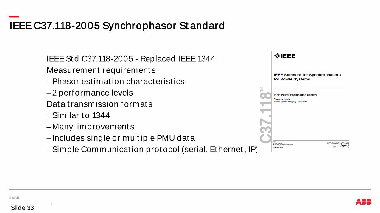
IEEE C37.118-2005 Synchrophasor St andard
IEEE St d C37.118-2005 - Replaced IEEE 1344 Measurement requirement s –Phasor est imat ion charact erist ics –2 performance levels Dat a t ransmission format s –Similar t o 1344 –Many improvement s – Includes single or mult iple PMU dat a –Simple Communicat ion prot ocol (serial, Et hernet , IP)
Slide 33

IEEE C37.118.1/ 2-2011 St andards
IEEE St d C37.118.1/ 2 – 2011 Replaced IEEE C37.118-2005 – C37.118.1 – Measurement s – C37.118.2 – Communicat ions (legacy) – Dynamic t est s added – 2 classes – Measurement (M) and Prot ect ion (P) – Higher report ing rat es recommended, new f ilt ering – Dynamic t est s, new conf igurat ion f rame (CFG-3) – Cont inuous Time Qualit y – Locked def init ion
Amendment t o IEEE C37.118.1a-2014 cont ains correct ions t o performance paramet ers
Slide 34

• IRIG-B is specif ied in IEEE C37.118 synchrophasor st andard • IRIG-B code is sent every second does not include year informat ion • IRIG-B can send UTC or Local t ime, and t ime zone sign specif icat ion changed
IEEE C37.118 st andard IRIG-B specif icat ion
Slid e 35

To receive year informat ion, ext ensions are needed – o ft en ca lled IEEE 1344 ext ens ions Ot her IRIG-B ext ens ions includ e Day lig ht s aving (DST) in effect , leap s econd , t im e q ua lit y, e t c
IEEE 1344 ext ens ions IRIG-B specif icat ion
Slid e 36

Ot her Synchrophasor St andards
IEC TR 61850-90-5 Approved and published in May 2012 – Transport of synchrophasor dat a – Int egrat ion wit h IEC 61850 syst ems – Rout able t ransport (t arget ed t o subst at ion t o subst at ion) – UDP t ransport , unicast and mult icast (preferred) – Securit y included – Mult iple communicat ions layers Joint IEC / IEEE 60255-118.1 st andard on synchrophasor measurement s is undergoing IEEE/ IEC approvals
Slide 37

IEEE Guides and Report s on Synchrophasors
IEEE PES PSRC Working Groups generat ed t he following document s IEEE Report Published in August 2013 Use of Synchrophasor Measurement s in Prot ect ive Relaying Applicat ions IEEE C37.242-2013 Published in March 2013 Guide for PMU Synchronizat ion, Calibrat ion, Test ing and Inst allat ion IEEE C37.244-2013 Published in May 2013 Guide for PDC Requirement s for Power Syst em Prot ect ion, Cont rol and Monit oring
Slide 38

Exercises on s ynchrop has or d efinit ion Synchrophasor exercises
Slid e 39
Ae j0
Acos(ωt)
Acos(ωt – π/2)
−π/2π/2
π0
−π/2π/2
π0
−π/2π/2
0
π/2π
0−π/2
π/2π
0−π/2
π/20
π
−π/2
Im
Re
Ae -jπ/2π
−π/2
Im
Re
(a) f(t) = Acos(ωt), θ = 0° (b) f(t) = Acos(ωt -π/2),θ = -π/2 (-90°)
Time Source Reference
New Second Pulse
π/2 π/2

Exercises on s ynchrop has or d efinit ion Synchrophasor exercises
Slid e 40
Us ing s ynchrop has or d efinit ion, d e t erm ine s ynchrop has or ang le Synchrop has or m ag nit ud e is RMS va lue
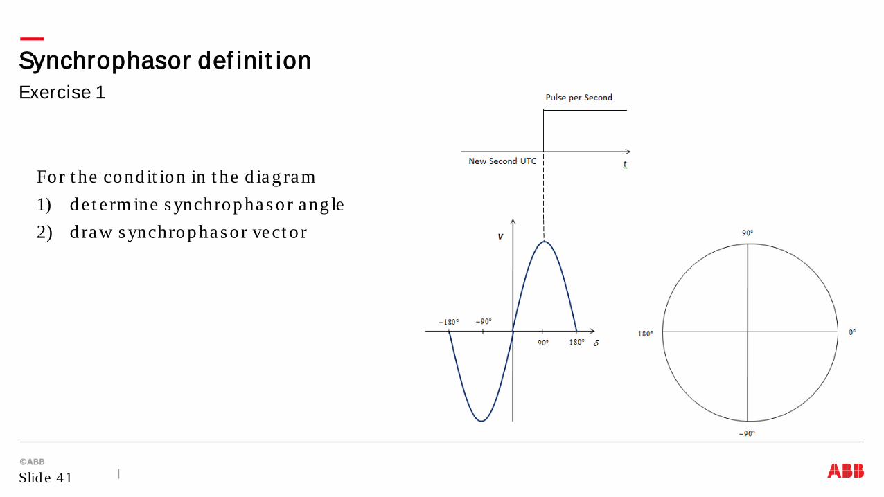
Exercise 1 Synchrophasor def init ion
Slid e 41
For t he cond it ion in t he d iag ram 1) d et erm ine s ynchrop has or ang le 2) d raw s ynchrop has or vect o r
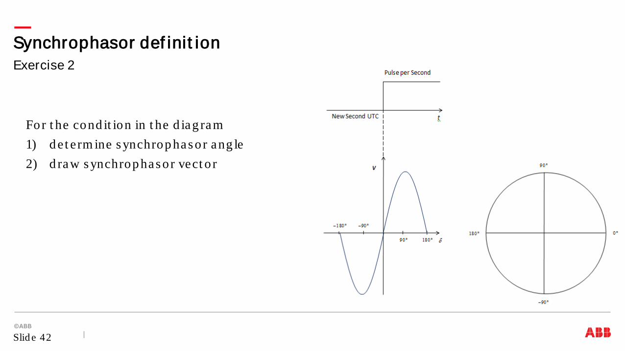
Exercise 2 Synchrophasor def init ion
Slid e 42
For t he cond it ion in t he d iag ram 1) d et erm ine s ynchrop has or ang le 2) d raw s ynchrop has or vect o r

Exercise 3 Synchrophasor def init ion
Slid e 43
For t he cond it ion in t he d iag ram 1) d et erm ine s ynchrop has or ang le 2) d raw s ynchrop has or vect o r
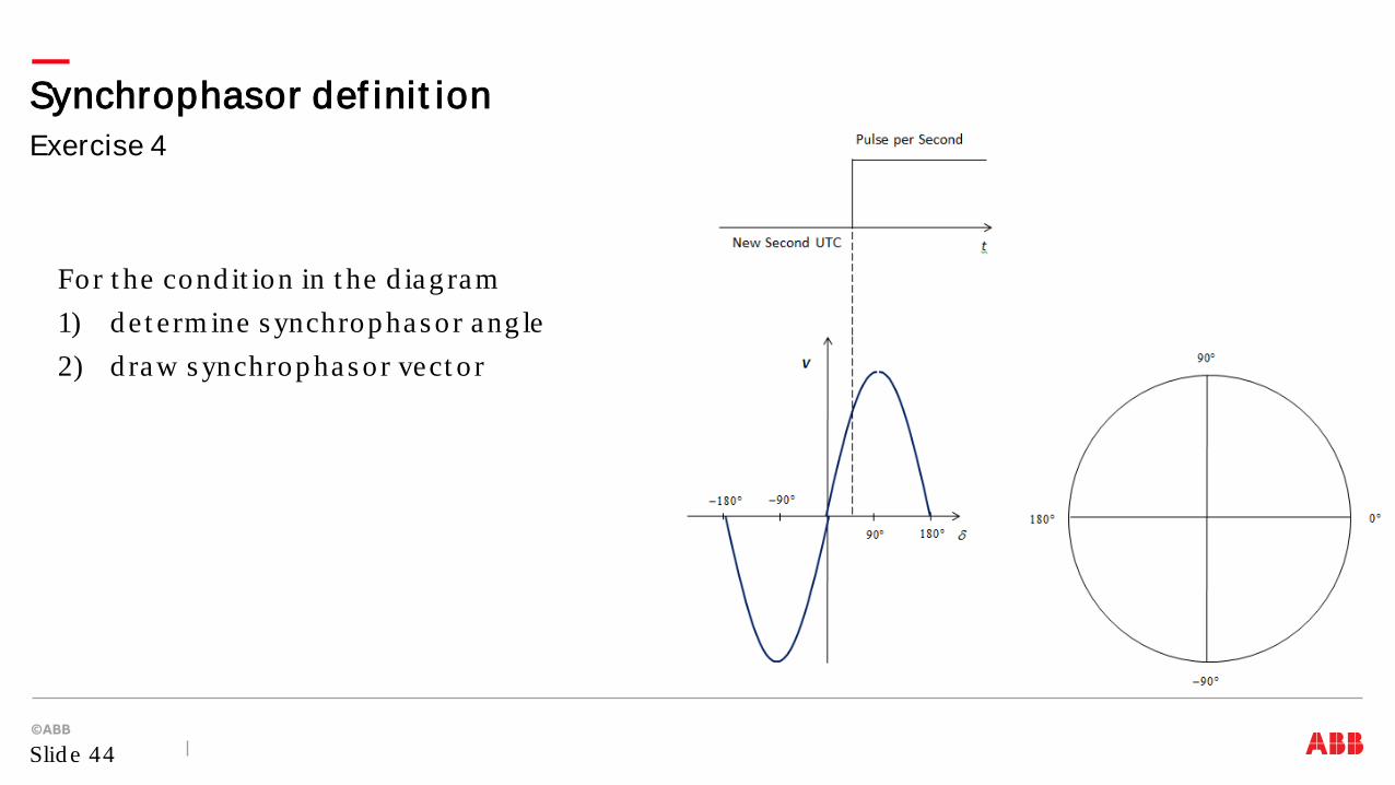
Exercise 4 Synchrophasor def init ion
Slid e 44
For t he cond it ion in t he d iag ram 1) d et erm ine s ynchrop has or ang le 2) d raw s ynchrop has or vect o r
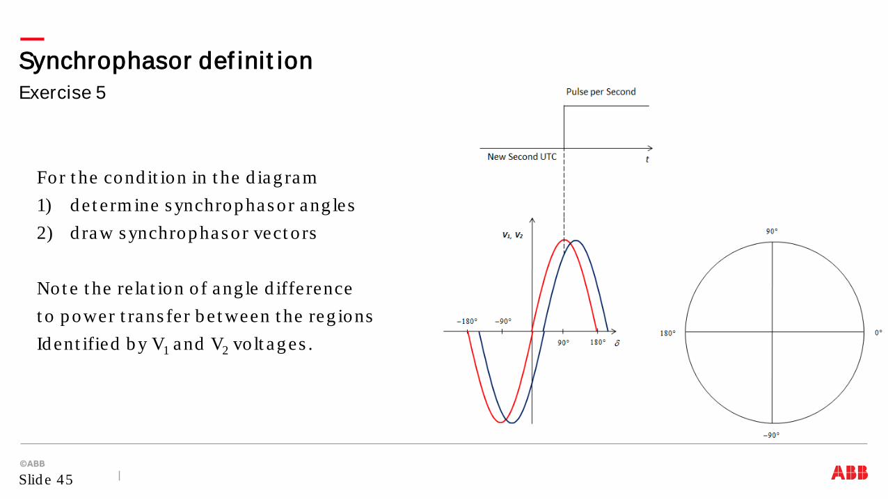
Exercise 5 Synchrophasor def init ion
Slid e 45
For t he cond it ion in t he d iag ram 1) d et erm ine s ynchrop has or ang les 2) d raw s ynchrop has or vect o rs Not e t he re la t ion o f ang le d ifference t o p ower t rans fer b e t ween t he reg ions Id ent ified b y V1 and V2 vo lt ag es .
Synchrophasor t echno log y us es p has ors o f current s and vo lt ag es t im es t am p ed t o UTC t im e Synchrop has or t echno log y b ring s m ore d e t a iled info rm a t ion ab out p ower s ys t em s , and is com p ared t o MRI in t he m ed ica l fie ld Synchrop has or t echno log y is d ep end ent on com m unica t ions and p recis e t im e s ynchroniza t ion The ab ilit y t o have s ynchronized p has ors from g eog rap hica lly d is p ers ed loca t ions in rea l t im e enab les b e t t e r cont ro l and p ro t ect ion o f p ower s ys t em s , lead ing t o hig her s ys t em s re liab ilit y
Conclusions
Slid e 46


![Distribution Synchrophasors: Overview of Applications ... · • connectivity via Ethernet, 4G wireless [cf presentation by Alex McEachern] Challenges for distribution synchrophasor](https://static.documents.pub/doc/80x56/5be3f93709d3f233038c89ea/distribution-synchrophasors-overview-of-applications-connectivity-via.jpg)


