Hard Gelatine capsules production Alejandro Tobón-atobonm3@eafit.edu.co/ Felipe López- flopezr@eafit.edu.co Mariana Flórez-mflorezu@eafit.edu.co/ Michell Ruiz-mruizc@eafit.edu.co Nicolás Peñuela-npenuelas@eafit.edu.co/ Valentina Ramírez-varamirezg@eafit.edu.co I. INTRODUCTION Pharmacaps is a Colombian company dedicated to the pro- duction of pills in the presentation of hard gelatin capsules filled with powdered medicine prescriptions. These types of capsules are solid pharmaceutical forms of two pieces: Cap and body; and some of its advantages in the industry are the great stability, the exact dosage, the low cost, the use of plant derivatives in ingredients to be environmentally friendly and finally an easily controllable release of the drug. Fig. 1. Logo The production of medicines in any presentation requires sophisticated equipment and processes in order to ensure a consistently high quality product. In the pharmaceutical industry, the dosage required by the regulatory standards of the World Health Organization and the Ministry of Health for each drug is of great importance in order to avoid errors that could have serious consequences for patients. Therefore, automating the capsule drug production process allows to increase productivity and ensure compliance with the demanding quality standards for this industry, avoiding human errors. The filling of hard gelatin capsules is an established technol- ogy, with equipment ranging from manual filling on a very small scale (24-200 capsules/hour) through semi-automatic filling on an intermediate scale (200-3000 capsules/hour) to fully automatic filling on a large scale (up to 150,000 capsules/hour). The difference between the many methods available is the way in which the dosage of material in the capsule body is measured. As the need for uniformity in content increases and regulations become more stringent, manufacturers must ensure that capsule weights are within a limited range throughout production. Because of this, an automated process is necessary to ensure high volume production of standardized capsules. Capsules are the second most frequently used solid oral dosage form after tablets. Demand for capsules is expected to increase substantially in the coming years, due to population growth and the expansion of the global pharmaceutical industry. Moreover, increased demand for nutraceuticals will also provide the global capsule market an opportunity to expand as various dietary supplements and functional foods are encapsulated to make them convenient for on-the-go consumption (Capuge,2017). Additionally, the demand for encapsulated ingredients is also booming in the cosmetic sector. As mentioned above, the market segment is in the pharmaceutical and cosmetic industry, where the target audience consists of those patients or customers of all ages who require a prescription powder encapsulated in hard gelatin. The daily production demand was set at 42,000 capsules per hour packed in blister packs. On the document below it will be explained all the process and requirements that are needed in order to created a automated production of hard gelatines capsules.This automation will be carried out by logic control, using sensors in the machines of each process to monitor the critical variables and PLC’s to control the actuators. This document is separated in sections which are:Introduction, which is explained the reasons of the project, the target market and a general introduction to medicine production.In the other hand, the process description has the layout of the plant and the flow diagram for each process that is involved. In addition to this, the instrumentation section contain pie diagrams that compare the sensor,actuators, acquisition systems and PLC used on this project and the SCADA which show the connection between the machines and the control room. The next section is the protocol for each process,on it is include the black box diagram, tables that mention the variable names assignee to make the FSM and a explanation of each step. Finally on the implementation, it is explain the human machine interfaces and one of the implementation made to represent one process on SIMULINK. II. OBJECTIVES A. General objective The general objective is to automate the manufacturing process of hard gelatin capsules filled with powdered drug formulations, ensuring high quality and an adequate produc- tion volume to meet demand. B. Specific objectives • Ensure accurate dosing that meets international stan- dards by using appropriate sensors for critical variables and effective control of the actuators. • Design optimal and detailed protocols in order for each sub-process to be performed successfully. • Develop functional FSM and implement them in MAT- LAB Simulink for each sub-process.
Pharmacaps is a Colombian company dedicated to the pro-duction of pills in the presentation of hard gelatin capsulesfilled with powdered medicine prescriptions. These types ofcapsules are solid pharmaceutical forms of two pieces: Capand body; and some of its advantages in the industry are thegreat stability, the exact dosage, the low cost, the use of plantderivatives in ingredients to be environmentally friendly andfinally an easily controllable release of the drug.
Fig. 1. Logo
The production of medicines in any presentation requiressophisticated equipment and processes in order to ensurea consistently high quality product. In the pharmaceuticalindustry, the dosage required by the regulatory standards ofthe World Health Organization and the Ministry of Healthfor each drug is of great importance in order to avoiderrors that could have serious consequences for patients.Therefore, automating the capsule drug production processallows to increase productivity and ensure compliance withthe demanding quality standards for this industry, avoidinghuman errors.The filling of hard gelatin capsules is an established technol-ogy, with equipment ranging from manual filling on a verysmall scale (24-200 capsules/hour) through semi-automaticfilling on an intermediate scale (200-3000 capsules/hour)to fully automatic filling on a large scale (up to 150,000capsules/hour). The difference between the many methodsavailable is the way in which the dosage of material inthe capsule body is measured. As the need for uniformityin content increases and regulations become more stringent,manufacturers must ensure that capsule weights are withina limited range throughout production. Because of this,an automated process is necessary to ensure high volumeproduction of standardized capsules.
Capsules are the second most frequently used solidoral dosage form after tablets. Demand for capsules isexpected to increase substantially in the coming years,due to population growth and the expansion of the globalpharmaceutical industry. Moreover, increased demand fornutraceuticals will also provide the global capsule market anopportunity to expand as various dietary supplements and
functional foods are encapsulated to make them convenientfor on-the-go consumption (Capuge,2017). Additionally, thedemand for encapsulated ingredients is also booming in thecosmetic sector. As mentioned above, the market segmentis in the pharmaceutical and cosmetic industry, where thetarget audience consists of those patients or customers ofall ages who require a prescription powder encapsulatedin hard gelatin. The daily production demand was set at42,000 capsules per hour packed in blister packs.On the document below it will be explained all the processand requirements that are needed in order to createda automated production of hard gelatines capsules.Thisautomation will be carried out by logic control, usingsensors in the machines of each process to monitor thecritical variables and PLC’s to control the actuators.This document is separated in sections whichare:Introduction, which is explained the reasons of theproject, the target market and a general introductionto medicine production.In the other hand, the processdescription has the layout of the plant and the flow diagramfor each process that is involved. In addition to this, theinstrumentation section contain pie diagrams that comparethe sensor,actuators, acquisition systems and PLC used onthis project and the SCADA which show the connectionbetween the machines and the control room. The nextsection is the protocol for each process,on it is include theblack box diagram, tables that mention the variable namesassignee to make the FSM and a explanation of each step.Finally on the implementation, it is explain the humanmachine interfaces and one of the implementation made torepresent one process on SIMULINK.
II. OBJECTIVES
A. General objective
The general objective is to automate the manufacturingprocess of hard gelatin capsules filled with powdered drugformulations, ensuring high quality and an adequate produc-tion volume to meet demand.
B. Specific objectives
• Ensure accurate dosing that meets international stan-dards by using appropriate sensors for critical variablesand effective control of the actuators.
• Design optimal and detailed protocols in order for eachsub-process to be performed successfully.
• Develop functional FSM and implement them in MAT-LAB Simulink for each sub-process.
• Propose suitable sensors to monitor the critical variablesof each sub-process and use logic control to guaranteethe correct functioning of the actuators.
III. PROCESS DESCRIPTION
The production process of hard gelatin capsules beginswith the reception and storage of the raw material. Then,there are two production lines: one dedicated to the man-ufacture of the capsules and one dedicated to the pro-cessing of the medicine with which the capsule is to befilled. The first line starts with the gelatin solution mixingprocess where several ingredients are combined at certaintemperature and viscosity conditions, then metal pins areimmersed in the solution, rotated and dried to form thecapsules; subsequently, the capsules are demoulded and goon to the encapsulation process. The second line starts withthe grinding and sieving processes to achieve the requiredsize of the drug components, then all the components aremixed and the mixture is dried; once the powdered drug isready, it is taken to the encapsulation process, in which thecapsule is filled. Finally, the capsules are blistered and theblister packs are packed in boxes and palletised.
A. Layout
The plant layout was designed taking into account theexistence of two production lines with parallel processes:the gelatin capsule manufacturing line (2.2) and the linefor processing the drug into powder (2.1-5); both lines startwith the reception of the raw material and its storage, andconverge in the encapsulation process (6), where the capsulesare filled with the powdered drug. Subsequently, the filledcapsules move through the line for blistering, packaging andpalletization processes. In addition, the plant has three rooms:One for raw material storage, one for quality control testingand one for finished product storage as shown in the figure.There is also a reception area for raw material trucks andanother for finished product dispatch.
Fig. 2. Layout
B. Storage
The storage room is where all raw materials are stored forfuture use. In addition, is where the materials are tested forquality control before they can be use. It is very importantto control the room temperature, humidity and light intensityto prevent any undesirable chemical reaction. The figure 3shows the flow chart of the storage process.
Fig. 3. Storage flow diagram
C. Capsule manufacturing line
Along this line are the processes necessary for the manu-facture of hard gelatin capsules, from the preparation of thegelatin solution to obtaining the final capsule that is going tobe filled with the powdered drug in the encapsulation process.Each process will be explained in more detail below.
1) Gelatin solution mixing: A concentrated solution ofgelatin (40-40 percentage by weight) and demineralizedwater that has been heated to 60-70°C is prepared. Dyesand pigments are then added to achieve the desired finalappearance of the capsule. The viscosity of the gelatinsolution is a critical parameter as it affects the subsequentmanufacturing process and plays an important role in thethickness of the capsule wall, so it must be measuredand adjusted as necessary with hot demineralized waterto achieve the desired specification. Once the specificationis met, the gelatin solution is transferred to temperature-controlled tanks. The figure 4 shows the flow chart of themixing process.
Fig. 4. Mixing flow diagram
2) Dip coating: The capsules are manufactured understrict climatic conditions by immersing pairs (body and lid)of standardized steel dowels arranged in rows on metal barsin an aqueous gelatin solution (obtained in the previous sub-process) kept at about 50°C in the storage tank. As the moldsare below the gelling temperature, the gelatin begins to forma thin layer or gelatin film on the molds, which will thenbecome the capsule. The figure 5 shows the flow chart ofthe dip coating process.
Fig. 5. Dip coating flow diagram
3) Dip coated pins rotation: After adsorption of thegelatin solution on the surface of the pins, the bar containingthe pins is removed and rotated several times to evenlydistribute the solution around the pins, as proper distribution
of the gelatin is critical for uniform and accurate capsulewall thickness and dome strength.
4) Dip coated pins drying: Once the gelatin is evenlydistributed in the mold, a conveyor belt is used to ensure thedrying of the capsules and take them to the next process. Thefigure 6 shows the flow chart of the dip-coated pins dryingprocess.
Fig. 6. Drying flow diagram
5) Demolding: The capsules are removed from thepunches,leaving the cap and body for the encapsulationprocess. The figure 7 shows the flow chart of the demoldingprocess.
Fig. 7. Demolding flow diagram
D. Drug processing line
1) Grinding: This process receives as input the pharma-ceutic to be processed as raw material ready to be grinded,after passing through all the quality verifications on thereception of the general process. The grinding recipientwhich has a pneumatic actuator inside is filled up with rawmaterial, and once the recipient reaches the required level forthe process to function properly, the recipient is closed andthe temperature of it starts to rise. The temperature plays akey aspect in the process, because for the raw material to beprocessed more efficiently, and more fluidly, it must reacha high temperature so the material can be grinded withoutthe machine truncating. After the set grinding time passes,the pneumatic actuator shuts down and after the temperaturelowers to room temperature so the processed material canunload for the next sub process. The figure 8 shows the flowchart of the grinding process.
Fig. 8. Grinding flow diagram
2) Sifting: Sifting is a simple process, which is in chargeof filtering by means of a kind of strainer, solids containingimpurities, dirt, or even lumps from the same mixture. Thisprocess is carried out in order to have a homogeneousmixture and to guarantee always the same structure in the
mixture. In the following flow chart 8 shows the siftingprocess. The figure 9 shows the flow chart of the siftingprocess.
Fig. 9. Sifting flow diagram
3) Mixing: The mixing process comes right after theraw materials were sifted and previous selected. It is whereall materials are mix with the reagents, water and heatto form the desired mix for the capsules that are beingmanufactured at the moment. Its running time, temperatureand mix ingredients depend of the content specifications.The figure 10 shows the flow chart of the mixing process.
Fig. 10. Mixing flow diagram
4) Drying: Drying is a fundamental process in this pro-cess, because it guarantees a dry, hygienic, and rested finalproduct. This is done by means of ventilation, sometimesnatural and in other situations artificial, being in this case anartificial ventilation by means of extractors or blades. Thefigure 11 shows the flow chart of the drying process.
Fig. 11. Drying flow diagram
5) Encapsulation: The encapsulation process is the pointwhich join the capsule manufacture and its content, thecapsules came separated and get filled with the content whichcames from drying process.Then,both ends of the capsule areunited by using pressure and heat. In conclusion, it is wherethe capsule gets created. Therefore, it is a critical point ofthe production process. The figure 12 shows the flow chartof the encapsulation process.
Fig. 12. Encapsulation flow diagram
6) Blistering: The blistering machine is a capsule plasticpackaging processor.Before starting the process, we mustbe sure that the capsules to package are finished (with thecontent inside).The machine starts rolling out the paper filmbobbin, then the film heats up to a specific temperaturecreating the cavities and filling them with the product. Oncethe capsules are inside the cavities, the machine covers themwith aluminium, that will be at the end cut and finallypackaged. The figure 13 shows the flow chart of the blisteringprocess.
Fig. 13. Blistering flow diagram
7) Packaging: In this process, the individual boxes andthe already blistered capsule packs are put together. Theprocess consists of inserting the blistered box into each in-dividual box through the machine specified for this purpose;then the individual boxes are transported to the next process.It must be ensured that the packaging is done correctly sincethis will be the first impression of the customer. This processis done using an automated machine which must ensure thatthe individual box contains a valid bar code in order tocontinue with the process flow.
8) Palletizing: This process starts with the boxes loadedwith the packaged pills coming through from the packagingsubprocess. Once every box reaches the end of the electricband the machine will push 4 boxes to a final platform inwhich an operating worker will place these 4 boxes on thepallet. While the worker does this, the machine prevents moreboxes from passing onto this platform for a determined setof time. After the worker has placed all boxes on the pallet,the machine resumes its functioning and repeats the process.The figure 14 shows the flow chart of the packaging andpalletizing process.
Fig. 14. Palletizing and Packaging flow diagram
IV. INSTRUMENTATION
A. SCADA Diagram
The SCADA diagram allows a high level overview of thecapsule’s manufacturing process, including all the devicesand actuators associated to each of the sub processes. Itperforms a supervisory operation using the diagram to showfunctional manufacturing levels using computerised control.This SCADA diagram is showed below this section, in the
figure 15. The symbols corresponding to the diagram areshown in the 43 in the annexes.
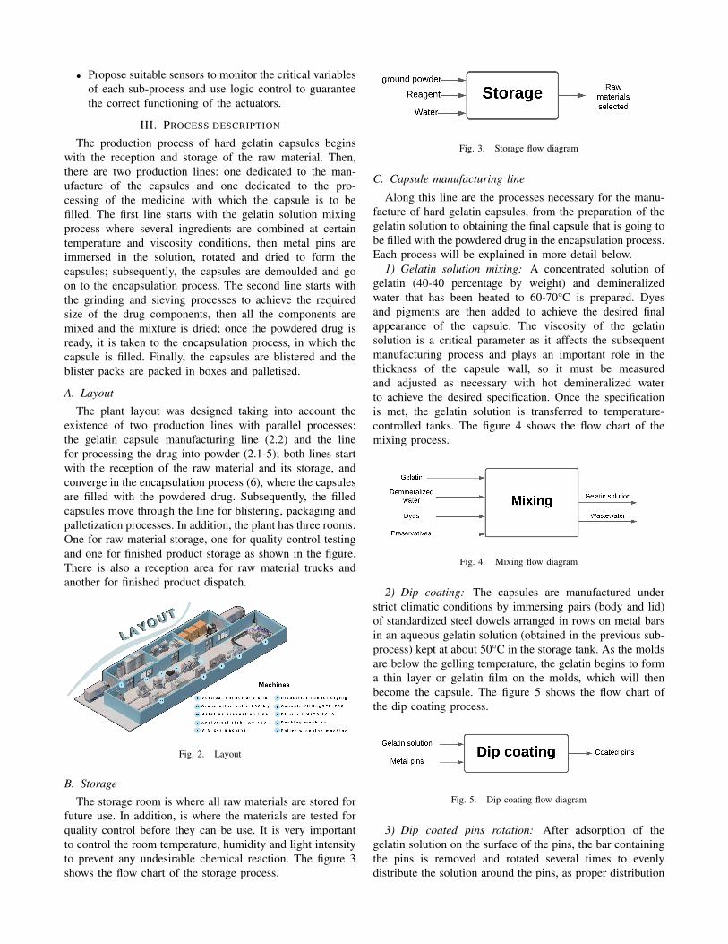
Fig. 15. SCADA diagram
B. Sensors and actuators used in the general process
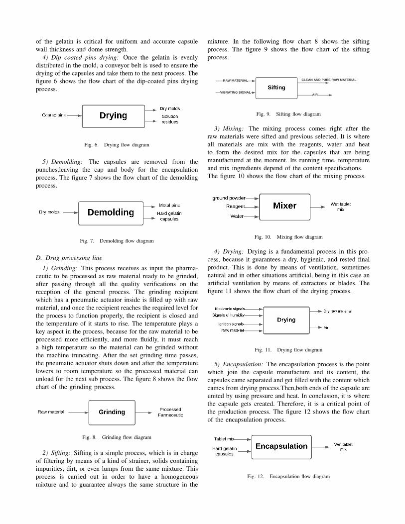
The total count of control elements used in the automationclassified by the sub-process they belong to, is as follows.The figure 16 shows the types and the total count of sensorsin all processes described before.
Fig. 16. Sensors in the company
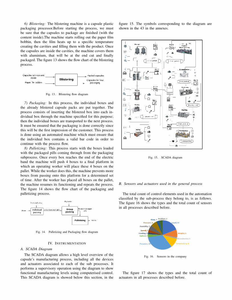
The figure 17 shows the types and the total count ofactuators in all processes described before.
Fig. 17. Actuators in the company
C. PLC’s
There are 9 large PLCs in total. Large PLCs refer toa large number of supported input/output signals, and themain reason for using this reference is that the companywants a control unit for each thread so that they can operateautonomously. The following are the graphs of the PLCreferences are shown below in table I.
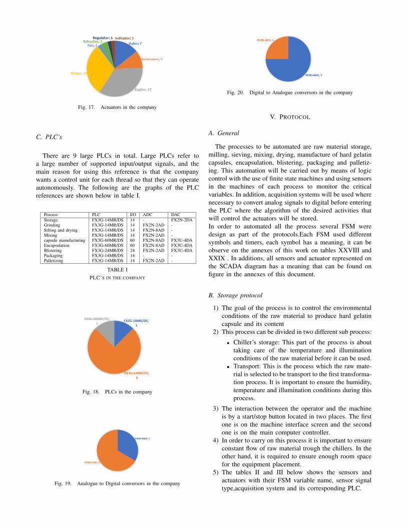
Fig. 19. Analogue to Digital conversors in the company
Fig. 20. Digital to Analogue conversors in the company
V. PROTOCOL
A. General
The processes to be automated are raw material storage,milling, sieving, mixing, drying, manufacture of hard gelatincapsules, encapsulation, blistering, packaging and palletiz-ing. This automation will be carried out by means of logiccontrol with the use of finite state machines and using sensorsin the machines of each process to monitor the criticalvariables. In addition, acquisition systems will be used wherenecessary to convert analog signals to digital before enteringthe PLC where the algorithm of the desired activities thatwill control the actuators will be stored.In order to automated all the process several FSM weredesign as part of the protocols.Each FSM used differentsymbols and timers, each symbol has a meaning, it can beobserve on the annexes of this work on tables XXVIII andXXIX . In additions, all sensors and actuator represented onthe SCADA diagram has a meaning that can be found onfigure in the annexes of this document.
B. Storage protocol
1) The goal of the process is to control the environmentalconditions of the raw material to produce hard gelatincapsule and its content
2) This process can be divided in two different sub process:
• Chiller’s storage: This part of the process is abouttaking care of the temperature and illuminationconditions of the raw material before it can be used.
• Transport: This is the process which the raw mate-rial is selected to be transport to the first transforma-tion process. It is important to ensure the humidity,temperature and illumination conditions during thisprocess.
3) The interaction between the operator and the machineis by a start/stop button located in two places. The firstone is on the machine interface screen and the secondone is on the main computer controller.
4) In order to carry on this process it is important to ensureconstant flow of raw material trough the chillers. In theother hand, it is required to ensure enough room spacefor the equipment placement.
5) The tables II and III below shows the sensors andactuators with their FSM variable name, sensor signaltype,acquisition system and its corresponding PLC.
Sensors Variable name Signal type Adquisiton systemPresence p1 Digital -Presence p2 Digital -Humidity h1 Digital -
TABLE IISENSOR TABLE FOR STORAGE PROCESS
Actuator Variable name adquisition systemConveyor Belt M Digital
Fan ve AnalogicTABLE III
ACTUATOR TABLE FOR STORAGE PROCESS
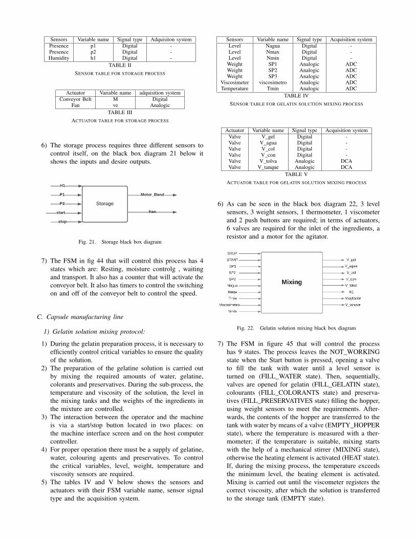
6) The storage process requires three different sensors tocontrol itself, on the black box diagram 21 below itshows the inputs and desire outputs.
Fig. 21. Storage black box diagram
7) The FSM in fig 44 that will control this process has 4states which are: Resting, moisture controlg , waitingand transport. It also has a counter that will activate theconveyor belt. It also has timers to control the switchingon and off of the conveyor belt to control the speed.
C. Capsule manufacturing line
1) Gelatin solution mixing protocol:
1) During the gelatin preparation process, it is necessary toefficiently control critical variables to ensure the qualityof the solution.
2) The preparation of the gelatine solution is carried outby mixing the required amounts of water, gelatine,colorants and preservatives. During the sub-process, thetemperature and viscosity of the solution, the level inthe mixing tanks and the weights of the ingredients inthe mixture are controlled.
3) The interaction between the operator and the machineis via a start/stop button located in two places: onthe machine interface screen and on the host computercontroller.
4) For proper operation there must be a supply of gelatine,water, colouring agents and preservatives. To controlthe critical variables, level, weight, temperature andviscosity sensors are required.
5) The tables IV and V below shows the sensors andactuators with their FSM variable name, sensor signaltype and the acquisition system.
Sensors Variable name Signal type Acquisition systemLevel Nagua Digital -Level Nmax Digital -Level Nmin Digital -
TABLE IVSENSOR TABLE FOR GELATIN SOLUTION MIXING PROCESS
Actuator Variable name Signal type Acquisition systemValve V_gel Digital -Valve V_agua Digital -Valve V_col Digital -Valve V_con Digital -Valve V_tolva Analogic DCAValve V_tanque Analogic DCA
TABLE VACTUATOR TABLE FOR GELATIN SOLUTION MIXING PROCESS
6) As can be seen in the black box diagram 22, 3 levelsensors, 3 weight sensors, 1 thermometer, 1 viscometerand 2 push buttons are required; in terms of actuators,6 valves are required for the inlet of the ingredients, aresistor and a motor for the agitator.
Fig. 22. Gelatin solution mixing black box diagram
7) The FSM in figure 45 that will control the processhas 9 states. The process leaves the NOT_WORKINGstate when the Start button is pressed, opening a valveto fill the tank with water until a level sensor isturned on (FILL_WATER state). Then, sequentially,valves are opened for gelatin (FILL_GELATIN state),colourants (FILL_COLORANTS state) and preserva-tives (FILL_PRESERVATIVES state) filling the hopper,using weight sensors to meet the requirements. After-wards, the contents of the hopper are transferred to thetank with water by means of a valve (EMPTY_HOPPERstate), where the temperature is measured with a ther-mometer; if the temperature is suitable, mixing startswith the help of a mechanical stirrer (MIXING state),otherwise the heating element is activated (HEAT state).If, during the mixing process, the temperature exceedsthe minimum level, the heating element is activated.Mixing is carried out until the viscometer registers thecorrect viscosity, after which the solution is transferredto the storage tank (EMPTY state).
2) Dip coating protocol:1) During this sub-process it is necessary to correctly
control the critical variables to guarantee the quality ofthe capsule coating.
2) The sub-process consists of immersing metal pins(moulds) in the tank containing the solution obtained inthe previous sub-process, in order to create the capsulesby coating.
3) The interaction between the operator and the machineis via a start/stop button located in two places: onthe machine interface screen and on the host computercontroller.
4) For proper operation there must be a continuous supplyof the solution and metal pins. For control, level,temperature and presence sensors are required, as wellas a resistor and a piston.
5) The tables VI and VI below shows the sensors andactuators with their FSM variable name, sensor signaltype,and the acquisition system.
Sensors Variable name Signal type Acquisition systemLevel Nmin Digital -
Temperature T Analogic -Presence Po Digital -Presence Pf Digital -
TABLE VISENSOR TABLE FOR DIP COATING PROCESS
Actuator Variable name Signal type Acquisition systemResistance R2 Analogic DCA
Piston P1 Digital -TABLE VII
ACTUATOR TABLE FOR DIP COATING PROCESS
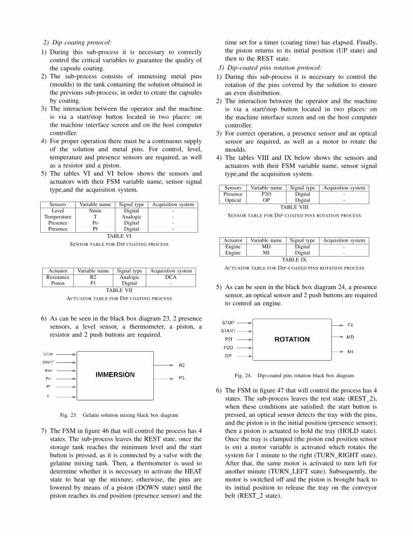
6) As can be seen in the black box diagram 23, 2 presencesensors, a level sensor, a thermometer, a piston, aresistor and 2 push buttons are required.
Fig. 23. Gelatin solution mixing black box diagram
7) The FSM in figure 46 that will control the process has 4states. The sub-process leaves the REST state, once thestorage tank reaches the minimum level and the startbutton is pressed, as it is connected by a valve with thegelatine mixing tank. Then, a thermometer is used todetermine whether it is necessary to activate the HEATstate to heat up the mixture; otherwise, the pins arelowered by means of a piston (DOWN state) until thepiston reaches its end position (presence sensor) and the
time set for a timer (coating time) has elapsed. Finally,the piston returns to its initial position (UP state) andthen to the REST state.
3) Dip-coated pins rotation protocol:1) During this sub-process it is necessary to control the
rotation of the pins covered by the solution to ensurean even distribution.
2) The interaction between the operator and the machineis via a start/stop button located in two places: onthe machine interface screen and on the host computercontroller.
3) For correct operation, a presence sensor and an opticalsensor are required, as well as a motor to rotate themoulds.
4) The tables VIII and IX below shows the sensors andactuators with their FSM variable name, sensor signaltype,and the acquisition system.
Sensors Variable name Signal type Acquisition systemPresence P2O Digital -Optical OP Digital -
TABLE VIIISENSOR TABLE FOR DIP-COATED PINS ROTATION PROCESS
Actuator Variable name Signal type Acquisition systemEngine MD Digital -Engine MI Digital -
TABLE IXACTUATOR TABLE FOR DIP-COATED PINS ROTATION PROCESS
5) As can be seen in the black box diagram 24, a presencesensor, an optical sensor and 2 push buttons are requiredto control an engine.
Fig. 24. Dip-coated pins rotation black box diagram
6) The FSM in figure 47 that will control the process has 4states. The sub-process leaves the rest state (REST_2),when these conditions are satisfied: the start button ispressed, an optical sensor detects the tray with the pins,and the piston is in the initial position (presence sensor);then a piston is actuated to hold the tray (HOLD state).Once the tray is clamped (the piston end position sensoris on) a motor variable is activated which rotates thesystem for 1 minute to the right (TURN_RIGHT state).After that, the same motor is activated to turn left foranother minute (TURN_LEFT state). Subsequently, themotor is switched off and the piston is brought back toits initial position to release the tray on the conveyorbelt (REST_2 state).
4) Dip-coated pins drying protocol:
1) During this sub-process it is necessary to ensure uniformdrying of the pins covered by the solution to ensureeven distribution. The idea is that the pins are driedwhile being transported by a conveyor belt to the nextsub-process.
2) The interaction between the operator and the machineis via a start/stop button located in two places: onthe machine interface screen and on the host computercontroller.
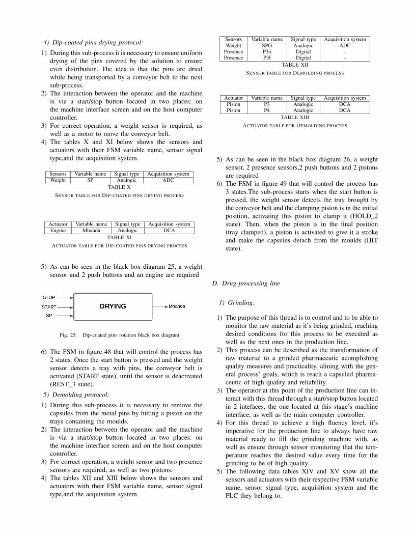
3) For correct operation, a weight sensor is required, aswell as a motor to move the conveyor belt.
4) The tables X and XI below shows the sensors andactuators with their FSM variable name, sensor signaltype,and the acquisition system.
Sensors Variable name Signal type Acquisition systemWeight SP Analogic ADC
TABLE XSENSOR TABLE FOR DIP-COATED PINS DRYING PROCESS
Actuator Variable name Signal type Acquisition systemEngine Mbanda Analogic DCA
TABLE XIACTUATOR TABLE FOR DIP-COATED PINS DRYING PROCESS
5) As can be seen in the black box diagram 25, a weightsensor and 2 push buttons and an engine are required
Fig. 25. Dip-coated pins rotation black box diagram
6) The FSM in figure 48 that will control the process has2 states. Once the start button is pressed and the weightsensor detects a tray with pins, the conveyor belt isactivated (START state), until the sensor is deactivated(REST_3 state).
5) Demolding protocol:
1) During this sub-process it is necessary to remove thecapsules from the metal pins by hitting a piston on thetrays containing the moulds.
2) The interaction between the operator and the machineis via a start/stop button located in two places: onthe machine interface screen and on the host computercontroller.
3) For correct operation, a weight sensor and two presencesensors are required, as well as two pistons.
4) The tables XII and XIII below shows the sensors andactuators with their FSM variable name, sensor signaltype,and the acquisition system.
Sensors Variable name Signal type Acquisition systemWeight SPG Analogic ADC
Presence P3o Digital -Presence P3f Digital -
TABLE XIISENSOR TABLE FOR DEMOLDING PROCESS
Actuator Variable name Signal type Acquisition systemPiston P3 Analogic DCAPiston P4 Analogic DCA
TABLE XIIIACTUATOR TABLE FOR DEMOLDING PROCESS
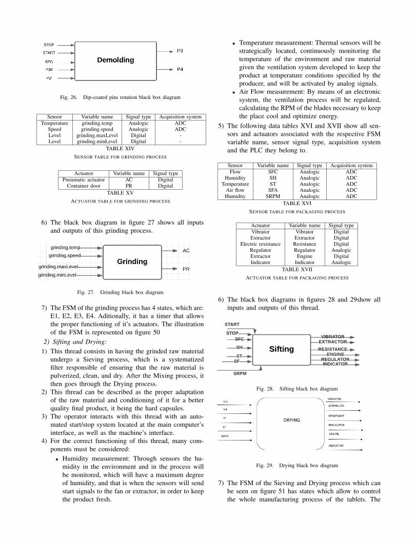
5) As can be seen in the black box diagram 26, a weightsensor, 2 presence sensors,2 push buttons and 2 pistonsare required
6) The FSM in figure 49 that will control the process has3 states.The sub-process starts when the start button ispressed, the weight sensor detects the tray brought bythe conveyor belt and the clamping piston is in the initialposition, activating this piston to clamp it (HOLD_2state). Then, when the piston is in the final position(tray clamped), a piston is activated to give it a strokeand make the capsules detach from the moulds (HITstate).
D. Drug processing line
1) Grinding:
1) The purpose of this thread is to control and to be able tomonitor the raw material as it’s being grinded, reachingdesired conditions for this process to be executed aswell as the next ones in the production line.
2) This process can be described as the transformation ofraw material to a grinded pharmaceutic acomplishingquality measures and practicality, alining with the gen-eral process’ goals, which is reach a capsuled pharma-ceutic of high quality and reliability.
3) The operator at this point of the production line can in-teract with this thread through a start/stop button locatedin 2 intefaces, the one located at this stage’s machineinterface, as well as the main computer controller.
4) For this thread to achieve a high fluency level, it’simperative for the production line to always have rawmaterial ready to fill the grinding machine with, aswell as ensure through sensor monitoring that the tem-perature reaches the desired value every time for thegrinding to be of high quality.
5) The following data tables XIV and XV show all thesensors and actuators with their respective FSM variablename, sensor signal type, acquisition system and thePLC they belong to.
Fig. 26. Dip-coated pins rotation black box diagram
Sensor Variable name Signal type Acquisition systemTemperature grinding.temp Analogic ADC
Speed grinding.speed Analogic ADCLevel grinding.maxLevel Digital -Level grinding.minLevel Digital -
TABLE XIVSENSOR TABLE FOR GRINDING PROCESS
Actuator Variable name Signal typePneumatic actuator AC Digital
Container door PR DigitalTABLE XV
ACTUATOR TABLE FOR GRINDING PROCESS
6) The black box diagram in figure 27 shows all inputsand outputs of this grinding process.
Fig. 27. Grinding black box diagram
7) The FSM of the grinding process has 4 states, which are:E1, E2, E3, E4. Aditionally, it has a timer that allowsthe proper functioning of it’s actuators. The illustrationof the FSM is represented on figure 50
2) Sifting and Drying:1) This thread consists in having the grinded raw material
undergo a Sieving process, which is a systematizedfilter responsible of ensuring that the raw material ispulverized, clean, and dry. After the Mixing process, itthen goes through the Drying process.
2) This thread can be described as the proper adaptationof the raw material and conditioning of it for a betterquality final product, it being the hard capsules.
3) The operator interacts with this thread with an auto-mated start/stop system located at the main computer’sinterface, as well as the machine’s interface.
4) For the correct functioning of this thread, many com-ponents must be considered:
• Humidity measurement: Through sensors the hu-midity in the environment and in the process willbe monitored, which will have a maximum degreeof humidity, and that is when the sensors will sendstart signals to the fan or extractor, in order to keepthe product fresh.
• Temperature measurement: Thermal sensors will bestrategically located, continuously monitoring thetemperature of the environment and raw materialgiven the ventilation system developed to keep theproduct at temperature conditions specified by theproducer, and will be activated by analog signals.
• Air Flow measurement: By means of an electronicsystem, the ventilation process will be regulated,calculating the RPM of the blades necessary to keepthe place cool and optimize energy.
5) The following data tables XVI and XVII show all sen-sors and actuators associated with the respective FSMvariable name, sensor signal type, acquisition systemand the PLC they belong to.
Sensor Variable name Signal type Acquisition systemFlow SFC Analogic ADC
Humidity SH Analogic ADCTemperature ST Analogic ADC
Air flow SFA Analogic ADCHumidity SRPM Analogic ADC
TABLE XVISENSOR TABLE FOR PACKAGING PROCESS
Actuator Variable name Signal typeVibrator Vibrator DigitalExtractor Extractor Digital
Electric resistance Resistance DigitalRegulator Regulator AnalogicExtractor Engine DigitalIndicator Indicator Analogic
TABLE XVIIACTUATOR TABLE FOR PACKAGING PROCESS
6) The black box diagrams in figures 28 and 29show allinputs and outputs of this thread.
Fig. 28. Sifting black box diagram
Fig. 29. Drying black box diagram
7) The FSM of the Sieving and Drying process which canbe seen on figure 51 has states which allow to controlthe whole manufacturing process of the tablets. The
states are: . In addition, it has timers that allow itsactuators to operate properly.
3) Mixing:1) The goal of the mixing process is to ensure all chemical
components are mixed to create the capsule content.2) The mixing process can be divided in four different sub
process:• Raw material reception: It is about separated the
materials in different tanks, depending on its char-acteristics.
• Weighing: This process is about measuring theweights of the different materials to conform themix wished to produce the capsule content
• Mixing: It is about mixing all the liquid and hardmaterials together for a period on a heated tank inorder to allow the reagents to produce the desiredmix. It is important to control the speed of the tankand the temperature.
• Transport: It is the process after the mixing, it isdesired to transport the final mix to the drying zone.
3) This process begins when the machine sensor detectsthat there are materials coming to the tanks and theoperator press the start button on the screen in thecontroller room.
4) It is required to ensure constant flow of material tobe mixed and energy to operate the machine and tocommunicate the information to the controller room.
5) The tables XVIII and XIX below shows all sensors andactuators that control the mixing process
Sensor Variable name Signal type Acquisition systemLevel N1 Digital -Level N2 Digital -
Temperature tem Analogics ADCPresence p1 Digital -
TABLE XVIIISENSOR TABLE FOR MIXING PROCESS
Actuator Variable name Signal typeConveyor Belt mt Digital
Valve val AnalogicHeat resistance r Analogic
Engine tank mb DigitalPiston P Digital
TABLE XIXACTUATOR TABLE FOR MIXING PROCESS
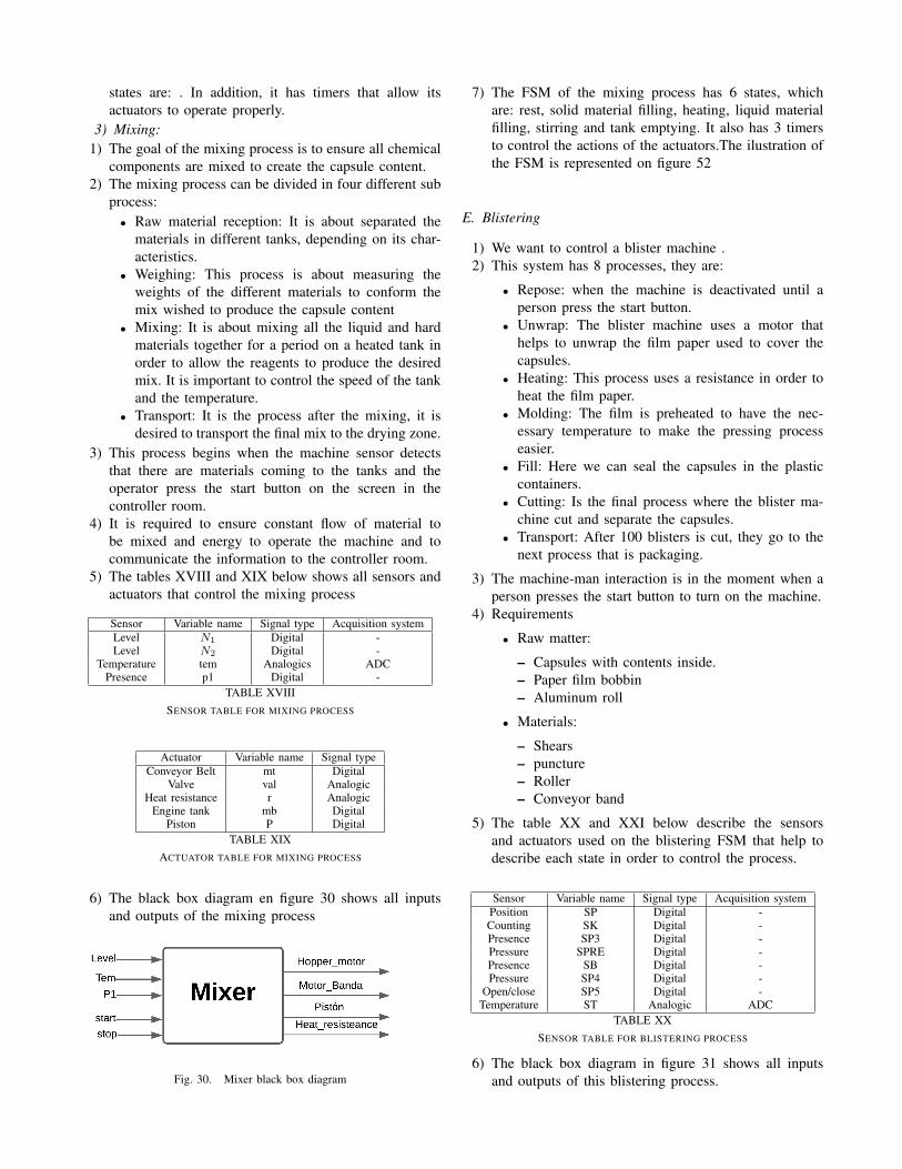
6) The black box diagram en figure 30 shows all inputsand outputs of the mixing process
Fig. 30. Mixer black box diagram
7) The FSM of the mixing process has 6 states, whichare: rest, solid material filling, heating, liquid materialfilling, stirring and tank emptying. It also has 3 timersto control the actions of the actuators.The ilustration ofthe FSM is represented on figure 52
E. Blistering
1) We want to control a blister machine .2) This system has 8 processes, they are:
• Repose: when the machine is deactivated until aperson press the start button.
• Unwrap: The blister machine uses a motor thathelps to unwrap the film paper used to cover thecapsules.
• Heating: This process uses a resistance in order toheat the film paper.
• Molding: The film is preheated to have the nec-essary temperature to make the pressing processeasier.
• Fill: Here we can seal the capsules in the plasticcontainers.
• Cutting: Is the final process where the blister ma-chine cut and separate the capsules.
• Transport: After 100 blisters is cut, they go to thenext process that is packaging.
3) The machine-man interaction is in the moment when aperson presses the start button to turn on the machine.
4) Requirements
• Raw matter:
– Capsules with contents inside.– Paper film bobbin– Aluminum roll
• Materials:
– Shears– puncture– Roller– Conveyor band
5) The table XX and XXI below describe the sensorsand actuators used on the blistering FSM that help todescribe each state in order to control the process.
Sensor Variable name Signal type Acquisition systemPosition SP Digital -Counting SK Digital -Presence SP3 Digital -Pressure SPRE Digital -Presence SB Digital -Pressure SP4 Digital -
Open/close SP5 Digital -Temperature ST Analogic ADC
TABLE XXSENSOR TABLE FOR BLISTERING PROCESS
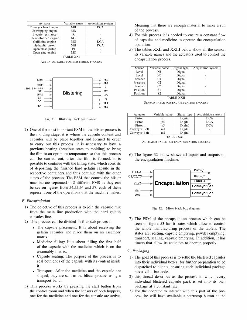
6) The black box diagram in figure 31 shows all inputsand outputs of this blistering process.
Actuator Variable name Acquisition systemConveyor band engine MB DCA
Unwrapping engine MD -Electric resistance R -
Thermoformed engine MT -Guillotine engine MG DCAHydraulic piston MH DCAOpen/close piston PI -Open gate engine MC -
TABLE XXIACTUATOR TABLE FOR BLISTERING PROCESS
Fig. 31. Blistering black box diagram
7) One of the most important FSM in the blister process isthe molding stage, it is where the capsule content andcapsules will be place together and formed In orderto carry out this process, it is necessary to have aprevious heating (previous state to molding) to bringthe film to an optimum temperature so that this processcan be carried out; after the film is formed, it ispossible to continue with the filling state, which consistsof depositing the finished hard gelatin capsule in therespective containers and thus continue with the otherstates of the process. The FSM that control the blistermachine are separated in 8 different FMS as they canbe see on figures from 54,55,56 and 57, each of themrepresent one of the operations that the machine makes.
F. Encapsulation
1) The objective of this process is to join the capsule mixfrom the main line production with the hard gelatincapsules line.
2) This process can be divided in four sub process:• The capsule placement: It is about receiving the
gelatin capsules and place them on an assemblymatrix
• Medicine filling: It is about filling the first halfof the capsule with the medicine which is on theassumably matrix.
• Capsule sealing: The purpose of the process is toseal both ends of the capsule with its content insideit.
• Transport: After the medicine and the capsule areshaped, they are sent to the blister process using atransport band.
3) This process works by pressing the start button fromthe control room and when the sensors of both hoppers,one for the medicine and one for the capsule are active.
Meaning that there are enough material to make a runof the process.
4) For this process it is needed to ensure a constant flowof capsules and medicine to operate the encapsulationoperation.
5) The tables XXII and XXIII below show all the sensor,its variable names and the actuators used to control theencapsulation process.
Sensor Variable name Signal type Acquisition systemLevel N1 Digital -Level N3 Digital -
Presence C1 Digital -Presence C2 Digital -Presence C3 Digital -Position S1 Digital -Position S2 Digital -
TABLE XXIISENSOR TABLE FOR ENCAPSULATION PROCESS
Actuator Variable name Signal type Acquisition systemPiston p1 Digital DCAPiston p4 Digital DCAPiston p5 Digital DCA
Conveyor Belt m1 Digital -Conveyor Belt m2 Digital -
TABLE XXIIIACTUATOR TABLE FOR ENCAPSULATION PROCESS
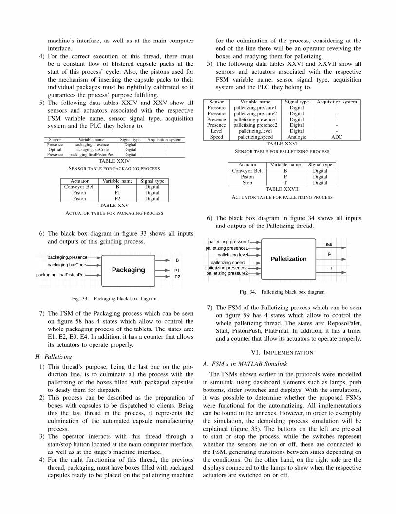
6) The figure 32 below shows all inputs and outputs onthe encapsulation machine.
Fig. 32. Mixer black box diagram
7) The FSM of the encapsulation process which can beseen on figure 53 has 6 states which allow to controlthe whole manufacturing process of the tablets. Thestates are: resting, capsule emptying, powder emptying,transport, sealing, capsule emptying. In addition, it hastimers that allow its actuators to operate properly.
G. Packaging
1) The goal of this process is to settle the blistered capsulesinto their individual boxes, for further preparation to bedispatched to clients, ensuring each individual packagehas a valid bar code.
2) this thread describes as the process in which everyindividual blistered capsule pack is set into its ownpackage at a constant rate.
3) For the operator to interact with this part of the pro-cess, he will have available a start/stop button at the
machine’s interface, as well as at the main computerinterface.
4) For the correct execution of this thread, there mustbe a constant flow of blistered capsule packs at thestart of this process’ cycle. Also, the pistons used forthe mechanism of inserting the capsule packs to theirindividual packages must be rightfully calibrated so itguarantees the process’ purpose fulfilling.
5) The following data tables XXIV and XXV show allsensors and actuators associated with the respectiveFSM variable name, sensor signal type, acquisitionsystem and the PLC they belong to.
Sensor Variable name Signal type Acquisition systemPresence packaging.presence Digital -Optical packaging.barCode Digital -
Presence packaging.finalPistonPos Digital -TABLE XXIV
SENSOR TABLE FOR PACKAGING PROCESS
Actuator Variable name Signal typeConveyor Belt B Digital
Piston P1 DigitalPiston P2 Digital
TABLE XXVACTUATOR TABLE FOR PACKAGING PROCESS
6) The black box diagram in figure 33 shows all inputsand outputs of this grinding process.
Fig. 33. Packaging black box diagram
7) The FSM of the Packaging process which can be seenon figure 58 has 4 states which allow to control thewhole packaging process of the tablets. The states are:E1, E2, E3, E4. In addition, it has a counter that allowsits actuators to operate properly.
H. Palletizing
1) This thread’s purpose, being the last one on the pro-duction line, is to culminate all the process with thepalletizing of the boxes filled with packaged capsulesto deady them for dispatch.
2) This process can be described as the preparation ofboxes with capsules to be dispatched to clients. Beingthis the last thread in the process, it represents theculmination of the automated capsule manufacturingprocess.
3) The operator interacts with this thread through astart/stop button located at the main computer interface,as well as at the stage’s machine interface.
4) For the right functioning of this thread, the previousthread, packaging, must have boxes filled with packagedcapsules ready to be placed on the palletizing machine
for the culmination of the process, considering at theend of the line there will be an operator reveiving theboxes and readying them for palletizing.
5) The following data tables XXVI and XXVII show allsensors and actuators associated with the respectiveFSM variable name, sensor signal type, acquisitionsystem and the PLC they belong to.
Sensor Variable name Signal type Acquisition systemPressure palletizing.pressure1 Digital -Pressure palletizing.pressure2 Digital -Presence palletizing.presence1 Digital -Presence palletizing.presence2 Digital -
Level palletizing.level Digital -Speed palletizing.speed Analogic ADC
TABLE XXVISENSOR TABLE FOR PALLETIZING PROCESS
Actuator Variable name Signal typeConveyor Belt B Digital
Piston P DigitalStop T Digital
TABLE XXVIIACTUATOR TABLE FOR PALLETIZING PROCESS
6) The black box diagram in figure 34 shows all inputsand outputs of the Palletizing thread.
Fig. 34. Palletizing black box diagram
7) The FSM of the Palletizing process which can be seenon figure 59 has 4 states which allow to control thewhole palletizing thread. The states are: ReposoPalet,Start, PistonPush, PlatFinal. In addition, it has a timerand a counter that allow its actuators to operate properly.
VI. IMPLEMENTATION
A. FSM’s in MATLAB Simulink
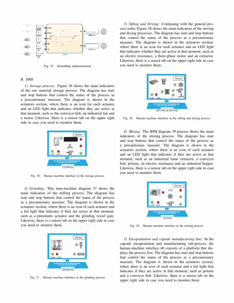
The FSMs shown earlier in the protocols were modelledin simulink, using dashboard elements such as lamps, pushbottoms, slider switches and displays. With the simulations,it was possible to determine whether the proposed FSMswere functional for the automatizing. All implementationscan be found in the annexes. However, in order to exemplifythe simulation, the demolding process simulation will beexplained (figure 35). The buttons on the left are pressedto start or stop the process, while the switches representwhether the sensors are on or off, these are connected tothe FSM, generating transitions between states depending onthe conditions. On the other hand, on the right side are thedisplays connected to the lamps to show when the respectiveactuators are switched on or off.
Fig. 35. Demolding implementation
B. HMI
1) Storage process: Figure 36 shows the main indicatorsof the raw material storage process. The diagram has startand stop buttons that control the status of the process asa precautionary measure. The diagram is shown in theactuators section, where there is an icon for each actuatorand an LED light that indicates whether they are active atthat moment, such as the conveyor belt, an industrial fan anda motor. Likewise, there is a sensor tab on the upper rightside in case you need to monitor them.
Fig. 36. Human machine interface in the storage process
2) Grinding: This man-machine diagram 37 shows themain indicators of the milling process. The diagram hasstart and stop buttons that control the status of the processas a precautionary measure. The diagram is shown in theactuators section, where there is an icon of each actuator anda led light that indicates if they are active at that moment,such as a pneumatic actuator and the grinding vessel gate.Likewise, there is a sensor tab on the upper right side in caseyou need to monitor them.
Fig. 37. Human machine interface in the grinding process
3) Sifting and Drying: Continuing with the general pro-cess order, Figure 38 shows the main indicators of the sievingand drying processes. The diagram has start and stop buttonsthat control the status of the process as a precautionarymeasure. The diagram is shown in the actuators section,where there is an icon for each actuator and an LED lightthat indicates whether they are active at that moment, such asan electric resistance, a three-phase motor and an extractor.Likewise, there is a sensor tab on the upper right side in caseyou need to monitor them.
Fig. 38. Human machine interface in the sifting and drying process
4) Mixing: The IHM diagram 39 process shows the mainindicators of the mixing process. The diagram has startand stop buttons that control the status of the process asa precautionary measure. The diagram is shown in theactuators section, where there is an icon of each actuatorand an LED light that indicates if they are active at thatmoment, such as an industrial fume extractor, a conveyorbelt, pistons, an electric resistance and an industrial hopper.Likewise, there is a sensor tab on the upper right side in caseyou need to monitor them.
Fig. 39. Human machine interface in the mixing process
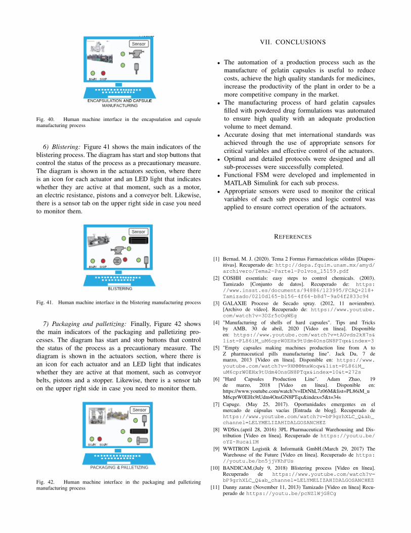
5) Encapsulation and capsule manufacturing line: In thecapsule encapsulation and manufacturing sub-process, thehuman-machine interface 40 consists of a platform that dis-plays the process live. The diagram has start and stop buttonsthat control the status of the process as a precautionarymeasure. The diagram is shown in the actuators section,where there is an icon of each actuator and a led light thatindicates if they are active at that moment, such as pistonsand a conveyor belt. Likewise, there is a sensor tab on theupper right side in case you need to monitor them.
Fig. 40. Human machine interface in the encapsulation and capsulemanufacturing process
6) Blistering: Figure 41 shows the main indicators of theblistering process. The diagram has start and stop buttons thatcontrol the status of the process as a precautionary measure.The diagram is shown in the actuators section, where thereis an icon for each actuator and an LED light that indicateswhether they are active at that moment, such as a motor,an electric resistance, pistons and a conveyor belt. Likewise,there is a sensor tab on the upper right side in case you needto monitor them.
Fig. 41. Human machine interface in the blistering manufacturing process
7) Packaging and palletizing: Finally, Figure 42 showsthe main indicators of the packaging and palletizing pro-cesses. The diagram has start and stop buttons that controlthe status of the process as a precautionary measure. Thediagram is shown in the actuators section, where there isan icon for each actuator and an LED light that indicateswhether they are active at that moment, such as conveyorbelts, pistons and a stopper. Likewise, there is a sensor tabon the upper right side in case you need to monitor them.
Fig. 42. Human machine interface in the packaging and palletizingmanufacturing process
VII. CONCLUSIONS
• The automation of a production process such as themanufacture of gelatin capsules is useful to reducecosts, achieve the high quality standards for medicines,increase the productivity of the plant in order to be amore competitive company in the market.
• The manufacturing process of hard gelatin capsulesfilled with powdered drug formulations was automatedto ensure high quality with an adequate productionvolume to meet demand.
• Accurate dosing that met international standards wasachieved through the use of appropriate sensors forcritical variables and effective control of the actuators.
• Optimal and detailed protocols were designed and allsub-processes were successfully completed.
• Functional FSM were developed and implemented inMATLAB Simulink for each sub process.
• Appropriate sensors were used to monitor the criticalvariables of each sub process and logic control wasapplied to ensure correct operation of the actuators.
REFERENCES
[1] Bernad, M. J. (2020). Tema 2 Formas Farmacéuticas sólidas [Diapos-itivas]. Recuperado de: http://depa.fquim.unam.mx/amyd/archivero/Tema2-Parte1-Polvos_15159.pdf
[2] COSHH essentials: easy steps to control chemicals. (2003).Tamizado [Conjunto de datos]. Recuperado de: https://www.insst.es/documents/94886/123995/FCAQ+218+Tamizado/0210d165-b156-4f64-b8d7-9a04f2833c94
[3] GALAXIE Proceso de Secado spray. (2012, 11 noviembre).[Archivo de vídeo]. Recuperado de: https://www.youtube.com/watch?v=3DZr5cOgWEg
[4] "Manufacturing of shells of hard capsules". Tips and Tricksby AMB, 30 de abril, 2020 [Video en línea]. Disponibleen: https://www.youtube.com/watch?v=tAGvds2kH7s&list=PL86iM_uM6cprW0EHx9tUdm4OnsGN8PTqx&index=3
[5] "Empty capsules making machines production line from A toZ pharmaceutical pills manufacturing line". Jack Du, 7 demarzo, 2013 [Video en línea]. Disponible en: https://www.youtube.com/watch?v=9XMMMmxWoqw&list=PL86iM_uM6cprW0EHx9tUdm4OnsGN8PTqx&index=10&t=272s
[6] "Hard Capsules Production Line". Adam Zhao, 19de marzo, 2018 [Video en línea]. Disponible en:https://www.youtube.com/watch?v=IDtNhL7z06M&list=PL86iM_uM6cprW0EHx9tUdm4OnsGN8PTqx&index=5&t=34s
[7] Capuge. (May 25, 2017). Oportunidades emergentes en elmercado de cápsulas vacías [Entrada de blog]. Recuperado dehttps://www.youtube.com/watch?v=bP9grhXLC_Q&ab_channel=LELYMELIZAHIDALGOSANCHEZ
[8] WDSrx.(april 28, 2016) 3PL Pharmaceutical Warehousing and Dis-tribution [Video en línea]. Recuperado de https://youtu.be/oYZ-RucaiIM
[9] WWITRON Logistik & Informatik GmbH.(March 29, 2017) TheWarehouse of the Future [Video en línea]. Recuperado de https://youtu.be/bn5jjVKhFUs
[10] BANDICAM.(July 9, 2018) Blistering process [Video en línea].Recuperado de https://www.youtube.com/watch?v=bP9grhXLC_Q&ab_channel=LELYMELIZAHIDALGOSANCHEZ
[11] Danny zarate (November 11, 2013) Tamizado [Video en línea] Recu-perado de https://youtu.be/pcNZlWjG8Cg