XAPP1221 (v1.0) January 12, 2015 www.xilinx.com 1 Summary This application note is intended to be a getting started guide for new users of ENEA OSE BSP on the Zynq®-7000 AP SoC. The document contains the following sections: • Building OSE for the Zynq-7000 AP SoC goes over the steps to download, configure and build the OSE BSP, as well as how to boot the device and set up the remote debugging capabilities using ENEA Optima tools. • Building and Debugging an OSE Application for the Zynq-7000 AP SoC explains how to create a simple application running within OSE, and then sets up the debugging feature of the ENEA tools, and explains how to perform basic debugging of OSE running on a Zynq-7000 AP SoC. • Accessing a Peripheral in the Programmable Logic goes over the configuration needed to access a peripheral in the programmable logic of the Zynq-7000 SoC, showing the ability for ENEA Optima tools to develop applications and drivers targeting custom IP instantiated within the Zynq-7000 AP SoC programmable logic. You can download the reference design files for this application note from the Xilinx® website. For detailed information about the design files, see Reference Design. Hardware and Software Requirements Software Requirements • Vivado® Design Suite, 2014.2. • Xilinx SDK 2014.2 • ENEA OSE5.7 • TFTP server application, such as tftpd64 Hardware Requirements • Xilinx ZC702 Development Board Application Note: Zynq-7000 AP SoC XAPP1221 (v1.0) January 12, 2015 Using ENEA OSE BSP for the Zynq-7000 AP SoC Author: Kester Aernoudt
Transcript
XAPP1221 (v1.0) January 12, 2015 www.xilinx.com 1
SummaryThis application note is intended to be a getting started guide for new users of ENEA OSE BSP on the Zynq®-7000 AP SoC. The document contains the following sections:
• Building OSE for the Zynq-7000 AP SoC goes over the steps to download, configure and build the OSE BSP, as well as how to boot the device and set up the remote debugging capabilities using ENEA Optima tools.
• Building and Debugging an OSE Application for the Zynq-7000 AP SoC explains how to create a simple application running within OSE, and then sets up the debugging feature of the ENEA tools, and explains how to perform basic debugging of OSE running on a Zynq-7000 AP SoC.
• Accessing a Peripheral in the Programmable Logic goes over the configuration needed to access a peripheral in the programmable logic of the Zynq-7000 SoC, showing the ability for ENEA Optima tools to develop applications and drivers targeting custom IP instantiated within the Zynq-7000 AP SoC programmable logic.
You can download the reference design f iles for this application note from the Xilinx® website. For detailed information about the design files, see Reference Design.
Installing OSEThe installation of OSE for the Zynq-7000 AP SoC is split into different components which are installed separately. The required components are:
• The OSE kernel
• The BSP for the Zynq-7000 AP SoC device
Optionally, but used for this application note, the ENEA development environment Optima can be installed as well. Optima is an Eclipse based environment that allows you to create, build, and debug the OSE kernel and modules, and also allows you monitor and analyze running targets, all done over Ethernet.
OSE Kernel
This image is typically named something similar to ose5_7_arm-BLXXXXXX_BLXXXXXX-image.zip, meaning a maintenance build of the OSE 5.7 version. The installation wizard walks you through a couple of steps in which you will be asked to enter the license key and installation path. The suggestion is to use the default installation path, and to select Typical installation when selecting the packages to install.
All documentation for this BSP can be found in the <OSE installation path>/doc folder.
BSP for the Zynq-7000 AP SoC Device
Similar to the OSE kernel itself, the Zynq-7000 BSP has to be installed using an installation wizard. The image itself is provided as an archive, similar to bsp_zynq7020_refsys_OSE5.7.1_BLXXXXXX_BLXXXXXX.zip. For this application note, the version BL770298 is used.
The default folder for the installation of the Zynq-7000 BSP is C:\Enea\BSP_Zynq7020_OSE5.7, and the Typical Installation can be used, which will install all the necessary packages and documentation.
Optima
As a last step, ENEA Optima IDE is installed, which will allow you to debug a running kernel and its modules. Again, the default location (C:\Enea\Optima2.8) and Typical Installation provide you with all you need to target and debug a Zynq-7000 device.
Once installation is complete, a full Start Menu will be populated with the member elements, as shown in Figure 1.
Configuring OSE Build EnvironmentAfter installation, the environment to build the kernel and run the tools has to be configured. This is done by modifying some makefiles, and creating a script to modify the environment before launching the tools.
Makefile Modifications
The OSE reference BSP comes with a makefile based build environment. It can also be integrated in an existing build environment, but this application note will use the provided system. To do so, some modifications have to be made for the exact environment and installation parameters used.
The reference BSP is created for the ZC702 board, and can be found in the <Zynq BSP install path>/refsys folder. Within this folder, the environment.mk f ile is the global configuration f ile for building the project. This file contains settings such as, but not limited to, Include Paths and Library Paths, along with Host and Target platform configuration details, etc.
However, two items need to be changed. Therefore, open the environment.mk f ile from the <Zynq BSP install path>/refsys folder and make the following modifications:
1. The OSEROOT variable needs to be set correctly. This is not needed when installing the Zynq-7000 BSP within the OSE base directory, but when installing multiple platforms BSPs, or when (as in this application note) installing the BSP outside of the OSE base folder, you need to configure the correct path to the sources of the OSE kernel. Look for the OSEROOT variable, and modify the path to reflect the installed environment:
OSEROOT ?= ../../../../OSE5.7.2_ARM
The OSEROOT variable has to point to the installation folder for the OSE kernel itself, relative to the build folder of the current project, which for a default installation would be <Zynq BSP Install Path>\refsys\rtose\zynq7020.
2. The correct platform needs to be selected. The default platform in the OSE 5.7.2 package was PowerPC® processor, which you need to change to arm-gcc. Look for the lines which contain the ARCH specif ication (see Figure 2), and modify or add an extra line underneath:
ARCH ?= arm-gcc
The ARCH variable configures the build system to use the correct cross compilation toolchain. This modif ication is not strictly needed when using the command line make utility, but is required when using the Optima Development Environment.
Environment Setup
The environment has to be configured for all tools to work correctly. The LM_LICENSE_FILE environmental variable has to be set, and point to the correct license file. Also, if not configured globally, the ENEA Cygwin path has to be added to the PATH environmental variable:
For convenience, create a batch f ile on your desktop with the following content:
set LM_LICENSE_FILE=C:\Enea\License_keys_SFK_TOOLSEVAL.TXTset PATH=%PATH%;C:\Enea\OSE5.7.2_ARM\cygwin\bin\C:\Enea\Optima2.8\optima_win32\eclipse.exe
This script will launch Optima with the correct path and license file in the environment.
Building the OSE Kernel for Zynq-7000 AP SoC DevicesThe installation of ENEA OSE comes with a Cygwin environment which can be used to compile the kernel and modules. Additionally, the Optima IDE can also be used. For this application note, the Optima IDE based approach will be used.
This will build both release and debug versions of the OSE kernel, which will be made visible in the GUI under the Binaries section in the Project Explorer, and are located in the <Zynq BSP Install Path>/refsys/rtose/zynq7020/obj/rtose_debug and <Zynq BSP Install Path>/refsys/rtose/zynq7020/obj/rtose_release folders. See Figure 8.
Running OSE on Zynq-7000 AP SoC DevicesAs described in the Zynq-7000 All Programmable SoC Technical Reference Manual (UG585) [Ref 1], Zynq-7000 AP SoC can use a selection of its hardened peripherals as a primary boot interface under initial control of the Zynq-7000 AP SoC BootROM. However, the process remains consistent in each and the need for a boot image containing a Boot header, First Stage Bootloader, Bitstream (optional) and a second stage bootloader/application is required at all times.
For the purpose of this application note, it is assumed that a prebuilt boot.bin image containing FSBL and a precompiled u-boot.elf has been downloaded and is available to the developer. The boot.bin image found on our Embedded Wiki [Ref 2] provides tftp boot capability, and the Vivado Design Suite 2014.2 version has been shown to work with this application note.
1. Download the boot.bin image and place it on a formatted SD Card.
2. Insert the SD card into the board.
3. Boot the platform with all appropriate cables connected.
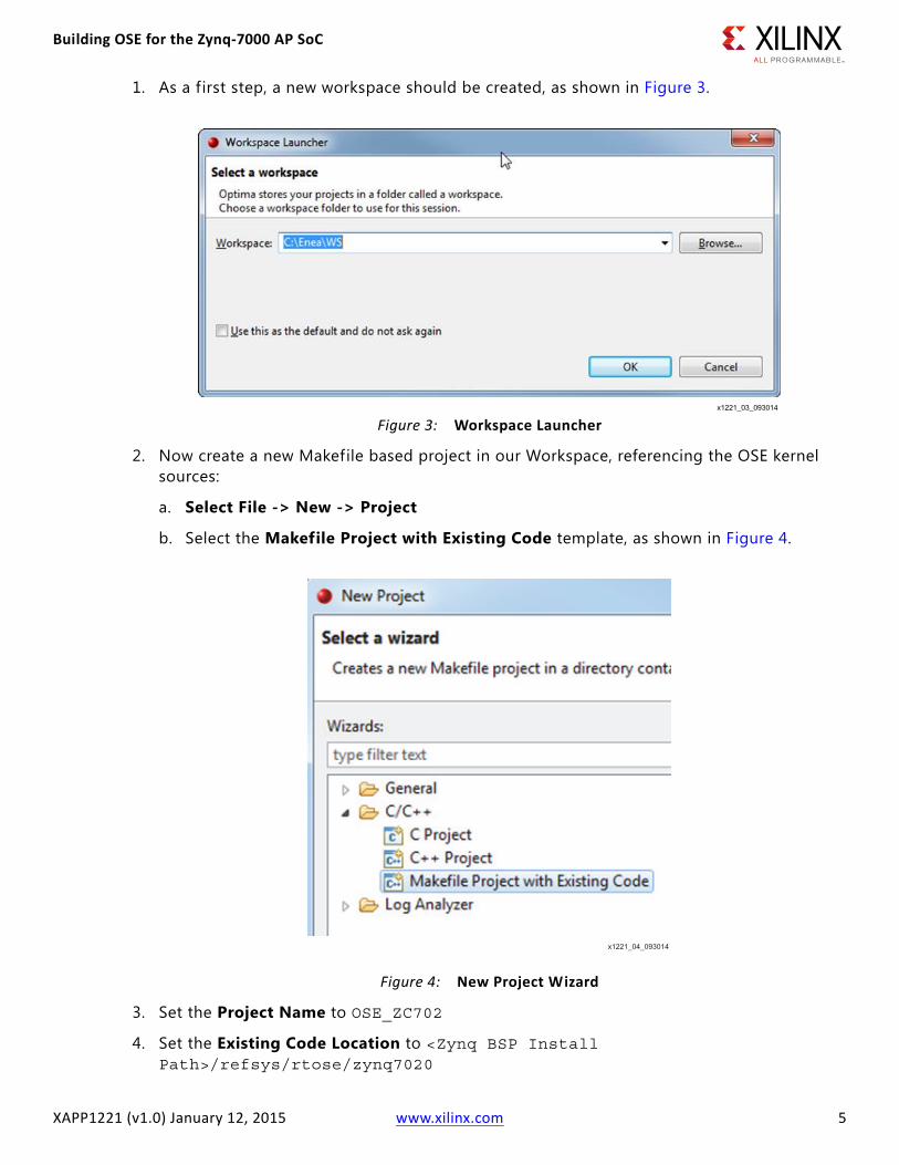
4. Open a serial console on the correct COM port and configure the terminal settings:
During boot, you should see the u-boot boot messages, which will show a download counter to start autoboot.
f. Select any key to stop this autoboot, as the default configuration is to launch Linux. See Figure 9.
Now that you are in the u-boot prompt, you can use different methods to load the actual OSE kernel image. For this application note, you will use a TFTP server on the host machine, and configure u-boot to fetch the kernel over TFTP.
5. Launch the tftp64 application, and store the rtose.bin (<Zynq BSP install path>\refsys\rtose\zynq7020\obj\rtose_debug\rtose.bin) f ile in the root of the tftp shared folder.
6. Configure the tftp host machine to have a f ixed IP address (192.168.1.1, for example), and start the tftp server. Make sure that your local f irewall allows tftp to be used on your machine (or disable the f irewall temporarily).
7. Now, from the u-boot prompt, issue the following commands to fetch the OSE kernel and boot it on the Zynq-7000 AP SoC:
XAPP1221 (v1.0) January 12, 2015 www.xilinx.com 11
8. Type help for an overview (see Figure 11) of the available commands that are supported by this kernel.
9. If there is a DHCP server in the network, no further configuration is needed. Otherwise, use the following command to set the IP address of the target:
Building and Debugging an OSE Application for the Zynq-7000 AP SoC
XAPP1221 (v1.0) January 12, 2015 www.xilinx.com 12
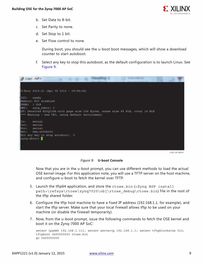
The actual IP address can be shown by entering the following (see Figure 12):
ifconfig eth0
Building and Debugging an OSE Application for the Zynq-7000 AP SoC
Building an OSE ModuleThe OSE BSP for Zynq-7000 AP SoC devices comes with several modules that can be added to the OSE kernel image or loaded at run time. See the ENEA OSE Device Drivers User's Guide [Ref 3] for more information. They can be used as is, or some are meant as an example of how to create and use modules within OSE. Such modules are located in the BSP install folder at
Building and Debugging an OSE Application for the Zynq-7000 AP SoC
XAPP1221 (v1.0) January 12, 2015 www.xilinx.com 13
<Zynq BSP install path>/refsys/modules. See Figure 13.
The example module used in this application note is the pingpong module. This is a very simple demonstration module, containing two processes sending signals to each other. A signal in OSE is used to pass messages between processes. It contains an ID, and can optionally contain other information as well. The pingpong module sends an integer value back and forth using such a signal. See the ENEA OSE Device Drivers User's Guide [Ref 3] for more information on signals and their use.
Building and Debugging an OSE Application for the Zynq-7000 AP SoC
XAPP1221 (v1.0) January 12, 2015 www.xilinx.com 14
The ping process creates a signal and sends it to the pong process, and this pong process receives the signal, increments a counter variable within this signal, and sends it back.
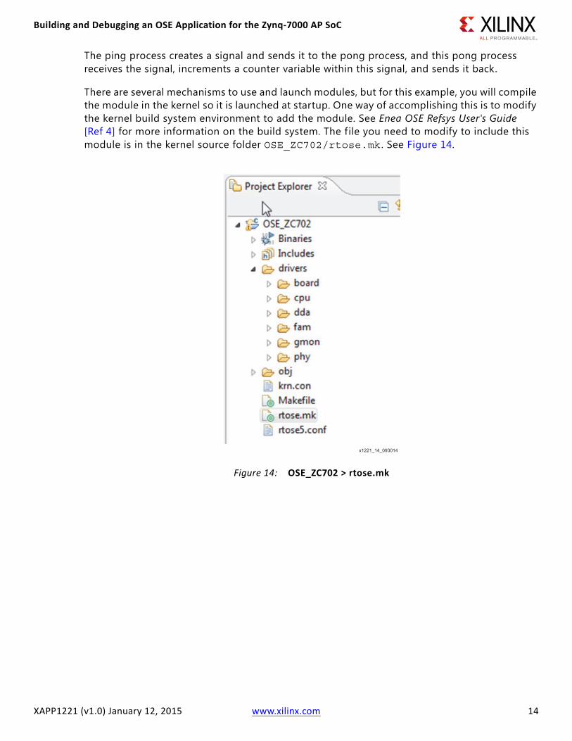
There are several mechanisms to use and launch modules, but for this example, you will compile the module in the kernel so it is launched at startup. One way of accomplishing this is to modify the kernel build system environment to add the module. See Enea OSE Refsys User's Guide [Ref 4] for more information on the build system. The file you need to modify to include this module is in the kernel source folder OSE_ZC702/rtose.mk . See Figure 14.
Building and Debugging an OSE Application for the Zynq-7000 AP SoC
XAPP1221 (v1.0) January 12, 2015 www.xilinx.com 15
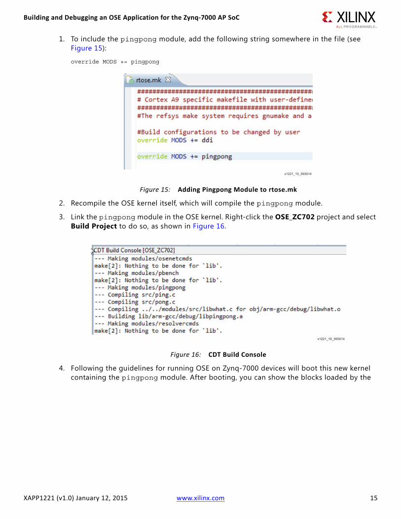
1. To include the pingpong module, add the following string somewhere in the file (see Figure 15):
override MODS += pingpong
2. Recompile the OSE kernel itself, which will compile the pingpong module.
3. Link the pingpong module in the OSE kernel. Right-click the OSE_ZC702 project and select Build Project to do so, as shown in Figure 16.
4. Following the guidelines for running OSE on Zynq-7000 devices will boot this new kernel containing the pingpong module. After booting, you can show the blocks loaded by the
Building and Debugging an OSE Application for the Zynq-7000 AP SoC
XAPP1221 (v1.0) January 12, 2015 www.xilinx.com 16
kernel by issuing the bl command, as shown in Figure 17.
5. Similarly, use the ps command to show the running processes, which include our ping and pong processes, as shown in Figure 18.
Debugging an Application using OptimaTo set up the connection between the ZC702 board running the OSE kernel and the Optima IDE, a new hardware target should be configured in Optima.
Building and Debugging an OSE Application for the Zynq-7000 AP SoC
XAPP1221 (v1.0) January 12, 2015 www.xilinx.com 18
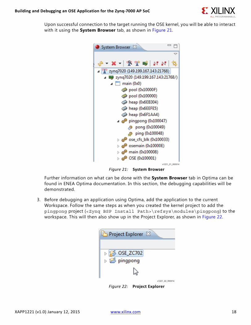
Upon successful connection to the target running the OSE kernel, you will be able to interact with it using the System Browser tab, as shown in Figure 21.
Further information on what can be done with the System Browser tab in Optima can be found in ENEA Optima documentation. In this section, the debugging capabilities will be demonstrated.
3. Before debugging an application using Optima, add the application to the current Workspace. Follow the same steps as when you created the kernel project to add the pingpong project (<Zynq BSP Install Path>\refsys\modules\pingpong) to the workspace. This will then also show up in the Project Explorer, as shown in Figure 22.
Building and Debugging an OSE Application for the Zynq-7000 AP SoC
XAPP1221 (v1.0) January 12, 2015 www.xilinx.com 19
Both the OSE kernel and the pingpong module projects can be built from within the Optima environment as well. For example, Project > Build All will build the current project debug and release versions.
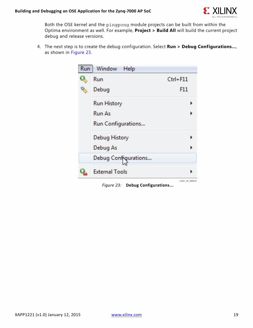
4. The next step is to create the debug configuration. Select Run > Debug Configurations…, as shown in Figure 23.
Building and Debugging an OSE Application for the Zynq-7000 AP SoC
XAPP1221 (v1.0) January 12, 2015 www.xilinx.com 20
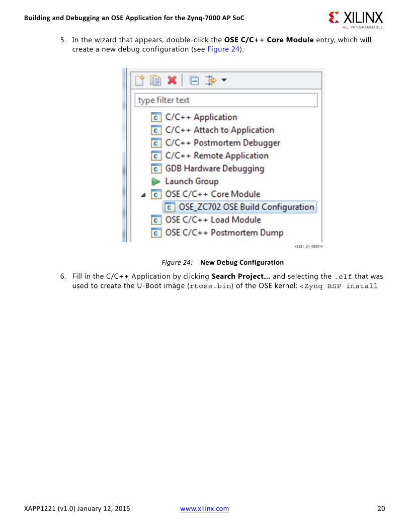
5. In the wizard that appears, double-click the OSE C/C++ Core Module entry, which will create a new debug configuration (see Figure 24).
6. Fill in the C/C++ Application by clicking Search Project… and selecting the .elf that was used to create the U-Boot image (rtose.bin) of the OSE kernel: <Zynq BSP install
Building and Debugging an OSE Application for the Zynq-7000 AP SoC
XAPP1221 (v1.0) January 12, 2015 www.xilinx.com 22
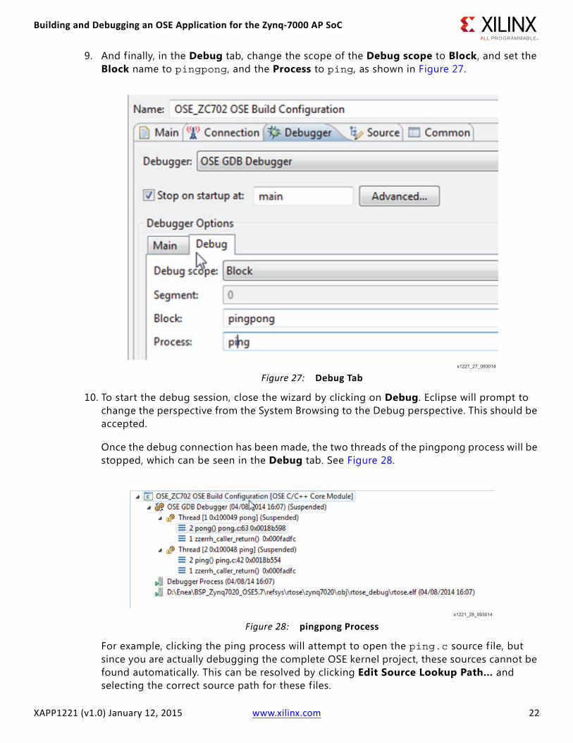
9. And finally, in the Debug tab, change the scope of the Debug scope to Block , and set the Block name to pingpong, and the Process to ping, as shown in Figure 27.
10. To start the debug session, close the wizard by clicking on Debug. Eclipse will prompt to change the perspective from the System Browsing to the Debug perspective. This should be accepted.
Once the debug connection has been made, the two threads of the pingpong process will be stopped, which can be seen in the Debug tab. See Figure 28.
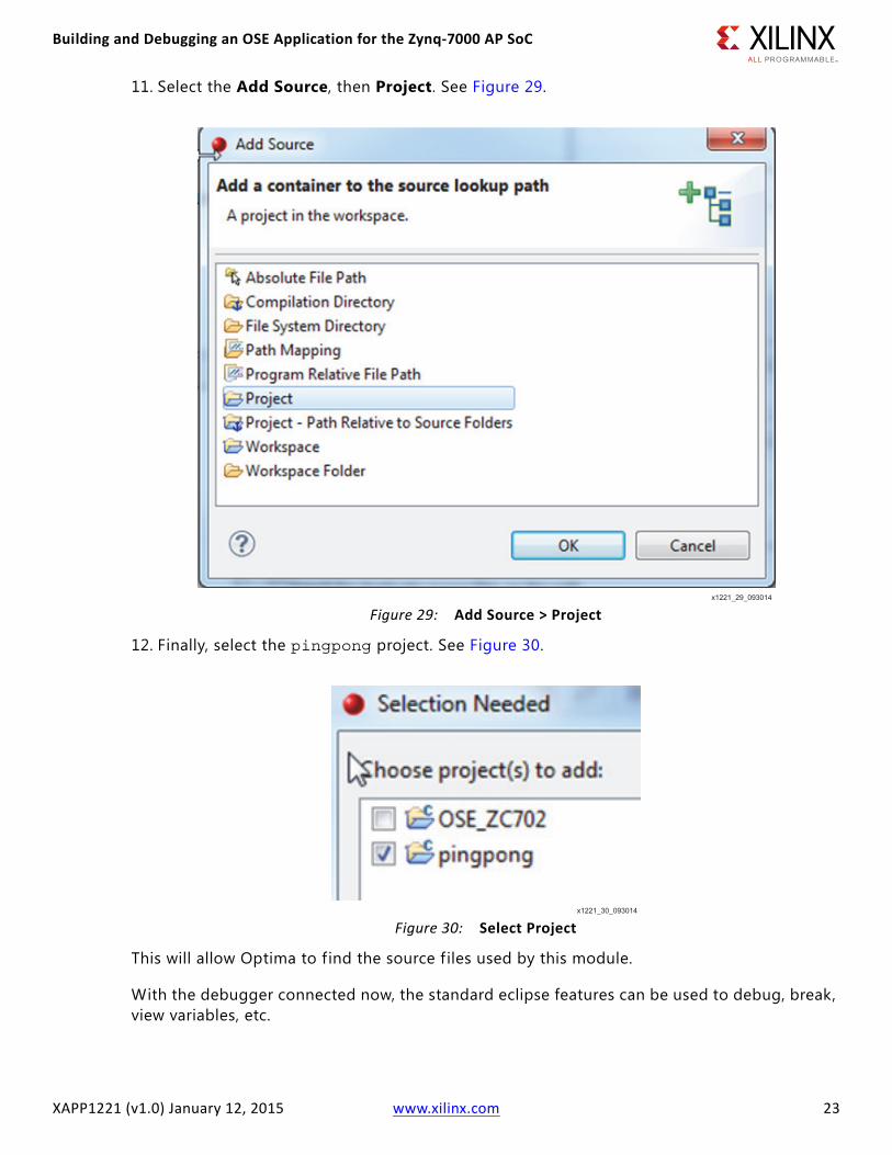
For example, clicking the ping process will attempt to open the ping.c source f ile, but since you are actually debugging the complete OSE kernel project, these sources cannot be found automatically. This can be resolved by clicking Edit Source Lookup Path… and selecting the correct source path for these files.
XAPP1221 (v1.0) January 12, 2015 www.xilinx.com 24
Accessing a Peripheral in the Programmable LogicInclusion of two general purpose AXI Master interfaces between the PS and the programmable logic ensures that user IP cores within the programmable logic are memory mapped in the same way that each of the peripherals within the PS are memory mapped. See the Zynq-7000 All Programmable SoC Technical Reference Manual (UG585) [Ref 1] for details. This common memory mapped approach ensures that access to peripherals, whether they are within the processing system or programmable logic, is an act of accessing a device-specif ic memory region.
In this section, you will modify the pingpong example application to show how to access a peripheral in the Programmable Logic.
Vivado IP Integrator Hardware DesignThe hardware design used for this section is created using the Vivado IP Integrator tools. The details of how to create such a design is out of scope for this application note, but can be found in Vivado Design Suite User Guide: Embedded Processor Hardware Design (UG898) [Ref 5] and Vivado Design Suite Tutorial: Embedded Processor Hardware Design (UG940) [Ref 6]. The project you will use is the Zynq example design, available in the 2014.2 Vivado release, which contains only the processing system, a block RAM controller, and an AXI GPIO peripheral in the programmable logic, driving four LEDs on the board. See Figure 31.
XAPP1221 (v1.0) January 12, 2015 www.xilinx.com 25
The memory map of this design is also configured in the IP Integrator environment, as shown in Figure 32.
For your convenience, the implemented bitstream is available for download (see Reference Design) with this application note.
After the implementation of this design, you also need to generate a First Stage Bootloader to configure the Processing Subsystem as defined by the IP Integrator project. There are multiple methods to create this First Stage bootloader, for example using XSDK (see [Ref 7]). A precompiled FSBL is also included in the attached reference design.
Example Application ModificationFor the simple example hardware design, you will modify the pingpong example to access our GPIO peripheral in the programmable logic. The modifications are done in the pong.c f ile, which will take the counter value in the signal that is sent between the ping and pong process, and drive the LEDs with this value. The only modification needed for this purpose is to configure the AXI GPIO peripheral to make all GPIO outputs:
Xil_Out32(GPIO_TRI_ADDR, 0x0);
And then, when a signal is received, you need to drive the LEDs with this value:
Xil_Out32(GPIO_DATA_ADDR, new_value);
The I/O functions by reading and writing from the correct memory location, and are defined as follows:
XAPP1221 (v1.0) January 12, 2015 www.xilinx.com 26
OSE Kernel ModificationsBecause OSE uses the MMU to access and protect memory regions, you also need to modify its configuration to be able to access our peripheral in the Programmable Logic. By default, the MMU is not configured to allow access to the memory regions used by the two Master AXI interfaces. OSE has multiple methods to modify this MMU configuration, both dynamically and statically. See the ENEA OSE Architecture User's Guide [Ref 8] for more information. For this example, a static configuration was selected.
The static configuration of the MMU is done in the f ile <Zynq BSP install path>/refsys/rtose/zynq7020/rtose5.conf. To add a memory region to the MMU, add the following line to the file, as shown in Figure 33:
This will allow OSE to access the memory region of our AXI GPIO peripheral located in the programmable logic, without using caches.
Now you can rebuild the OSE kernel, following the steps of Building the OSE Kernel for Zynq-7000 AP SoC Devices.
Booting Zynq-7000 AP SoC Devices using a Bitfile and Updated KernelBefore you can run the updated kernel image on our ZC702 board, you have to make sure that the programmable logic is configured with our custom hardware design. One method to accomplish this is to update the boot image to include this bitf ile, which will then during the boot process be used by the First Stage Bootloader to configure the programmable logic, before U-boot will get loaded and executed. To create a new boot image, use the tool bootgen, which is configured by a .bif f ile (ose.bif) containing the different partitions in the boot image. For more information on creating a boot image and using the bootgen application, see UG821, Appendix A: Using Bootgen [Ref 9].
XAPP1221 (v1.0) January 12, 2015 www.xilinx.com 27
Where:
• fsbl.elf is the fsbl created in the previous section, Vivado IP Integrator Hardware Design.
• zynq_1_wrapper.bit is the bitfile created in the same section.
• u-boot.elf is the same U-Boot used in Running OSE on the Zynq-7000 AP SoC.
To generate the new boot image, open an SDK command prompt, and execute the following:
bootgen -image ose.bif -o boot.bin
This will create a new boot.bin f ile, which needs to be copied on the SD card used to boot the board. For your convenience, the attached reference f iles contain all sources, as well as generated boot.bin f ile which can be used to boot the board.
Following the instructions from this document in Running OSE on Zynq-7000 AP SoC Devices, you now boot the ZC702 board using this updated image, which configures the programmable logic during the FSBL stage. After the OSE kernel is executed, the updated pingpong module will run, which will toggle the LEDs on the board. When connecting using Ethernet, and using Optima to debug the kernel, as explained in Debugging an Application using Optima, the pong process can be debugged.
ConclusionThis application note provides step-by-step instructions for running the OSE BSP on the Zynq-7000 SoC All Programmable device platform, and shows how to build and debug example applications accessing peripherals in the Processing System and Programmable Logic.
Reference DesignDownload the reference design files for this application note from the Xilinx website.
Table 1 shows the reference design matrix.
Table 1: Reference Design Matrix
Parameter Description
General
Developer Name Kester Aernoudt
Target Devices Zynq-7000 AP SoC
Source code provided? Y
Source code format (if provided) Block diagram/C
Design uses code or IP from existing reference design, application note, third-party or Vivado software? If yes, list.
XAPP1221 (v1.0) January 12, 2015 www.xilinx.com 28
References1. Zynq-7000 All Programmable SoC Technical Reference Manual (UG585)
2. Embedded Wiki http://www.wiki.xilinx.com/Zynq+Releases
3. Enea OSE Device Drivers User's Guide (installed with BSP)
4. Enea OSE Refsys User's Guide (installed with BSP)
5. Vivado Design Suite User Guide: Embedded Processor Hardware Design (UG898)
6. Vivado Design Suite Tutorial: Embedded Processor Hardware Design (UG940)
7. Chapter 3: Boot and Configuration (UG821)
8. Enea OSE Architecture User's Guide (Installed with OSE)
9. Appendix A: Using Bootgen (UG821)
Revision HistoryThe following table shows the revision history for this document.
Please Read: Important Legal NoticesThe information disclosed to you hereunder (the “Materials”) is provided solely for the selection and use of Xilinx products. To the maximum extent permitted by applicable law: (1) Materials are made available "AS IS" and with all faults, Xilinx hereby DISCLAIMS ALL WARRANTIES AND CONDITIONS, EXPRESS, IMPLIED, OR STATUTORY, INCLUDING BUT NOT LIMITED TO WARRANTIES OF MERCHANTABILITY, NON-INFRINGEMENT, OR FITNESS FOR ANY PARTICULAR PURPOSE; and (2) Xilinx shall not be liable (whether in contract or tort, including negligence, or under any other theory of liability) for any loss or damage of any kind or nature related to, arising under, or in connection with, the Materials (including your use of the Materials), including for any direct, indirect, special, incidental, or consequential loss or damage (including loss of data, profits, goodwill, or any type of loss or damage suffered as a result of any action brought by a third party) even if such damage or loss was reasonably foreseeable or Xilinx had been advised of the possibility of the same. Xilinx assumes no obligation to correct any errors contained in the Materials or to notify you of updates to the Materials or to product specifications. You may not reproduce, modify, distribute, or publicly display the Materials without prior written consent. Certain products are subject to the terms and conditions of Xilinx’s limited warranty, please refer to Xilinx’s Terms of Sale which can be viewed at http://www.xilinx.com/legal.htm#tos; IP cores may be subject to warranty and support terms contained in a license issued to you by Xilinx. Xilinx products are not designed or intended to be fail-safe or for use in any application requiring fail-safe performance; you assume sole risk and liability for use of Xilinx products in such critical applications, please refer to Xilinx’s Terms of Sale which can be viewed at http://www.xilinx.com/legal.htm#tos.
Hardware Verification
Hardware verif ied? Y
Platform used for verif ication ZC702 Development Board