Page 1
1To be presented by John McCloskey at the IEEE International Symposium on Electromagnetic Compatibility, National Harbor, MD, August 7-11, 2017
Hardware Demonstration:
Conducted Transients on
Spacecraft Primary Power Lines
August 9, 2017
2017 IEEE International Symposium on Electromagnetic Compatibility
John McCloskey
NASA/GSFC
Chief EMC Engineer
[email protected]
Jen Dimov
AS&D Inc. work performed for NASA/GSFC
EMC Engineer
[email protected]
https://ntrs.nasa.gov/search.jsp?R=20170007496 2020-03-14T15:34:05+00:00Z
Page 2
2To be presented by John McCloskey at the IEEE International Symposium on Electromagnetic Compatibility, National Harbor, MD, August 7-11, 2017
Acronym List
CE Conducted Emissions
CMCE Common Mode Conducted Emissions
CS Conducted Susceptibility
EMC Electromagnetic Compatibility
EMI Electromagnetic Interference
GEVS General Environmental Verification Specification
GSFC Goddard Space Flight Center
LISN Line Impedance Stabilization/Simulation Network
NASA National Aeronautics and Space Administration
Page 3
3To be presented by John McCloskey at the IEEE International Symposium on Electromagnetic Compatibility, National Harbor, MD, August 7-11, 2017
Introduction
One of the sources of potential interference on spacecraft primary power
lines is that of conducted transients resulting from equipment being
switched on and off of the bus
Susceptibility to such transients is addressed by the CS06 requirement of
MIL-STD-461/462 prior to 1993
This demonstration provides:
Basis for understanding of the sources of these transients
Analysis techniques for determining their worst-case characteristics (e.g.
magnitude and duration)
Guidelines for minimizing their magnitudes and applying the requirement
appropriately
Page 4
4To be presented by John McCloskey at the IEEE International Symposium on Electromagnetic Compatibility, National Harbor, MD, August 7-11, 2017
Anatomy of Transients
Normal transients on primary power bus result from equipment being switched on/off bus
Turn-on transient: negative going pulse
Turn-off transient: positive going pulse
Characteristics of transient (magnitude, duration) determined by interaction of common source
impedance with load impedance
TURN-ON TRANSIENT MODEL
(negative pulse)TURN-OFF TRANSIENT MODEL
(positive pulse)
Page 5
5To be presented by John McCloskey at the IEEE International Symposium on Electromagnetic Compatibility, National Harbor, MD, August 7-11, 2017
Power Distribution Harness Impedance Model
Common distribution impedance generally dominated by distribution wiring
Modeled as 2-wire transmission line
Lumped model sufficient for most applications
Line Impedance Stabilization/Simulation Network (LISN)
Used to represent wiring impedance
Based on lumped parameters; schematic usually looks like lumped model
Generally identified by inductance, e.g. 5 µH, 10 µH, 50 µH, etc.
DISTRIBUTED MODEL LUMPED MODEL (LISN)
Page 6
6To be presented by John McCloskey at the IEEE International Symposium on Electromagnetic Compatibility, National Harbor, MD, August 7-11, 2017
Power Distribution Harness Impedance Model (cont.)
Positive (+) and negative (-) bundles can be separated by 10s of cm
Typical distribution wiring length
Unmanned spacecraft: ~1 meter, ~ 1 µH
Larger platforms can have higher impedance buses; use LISNs ranging from 5 µH to
50 µH, depending on application
R
Z0
Typical parameters:
R/l = 3 mΩ/m
L/l = 1 µH/m
C/l = 10 pF/m
Z0 = 350 Ω
Page 7
7To be presented by John McCloskey at the IEEE International Symposium on Electromagnetic Compatibility, National Harbor, MD, August 7-11, 2017
Power Distribution Harness Impedance Model (cont.)
MIL-STD-461 50 μH LISN
MIL-STD-461 5 μH LISN
Page 8
8To be presented by John McCloskey at the IEEE International Symposium on Electromagnetic Compatibility, National Harbor, MD, August 7-11, 2017
Discrete Inductors from LISNs
Space Station LISN
Pair of 10 µH inductors
(11 µH as-measured)
Tegam 95300-50 LISN
50 µH
(51 µH as-measured)
5000 uF
Page 9
9To be presented by John McCloskey at the IEEE International Symposium on Electromagnetic Compatibility, National Harbor, MD, August 7-11, 2017
Turn-On Transient Simplified Model
For typical turn-on transients, inductance dominates common source impedance
Load capacitance is generally many orders of magnitude higher than the wiring
capacitance
Wiring capacitance may generally be ignored
Common source impedance may be modelled as bulk inductance
Page 10
10To be presented by John McCloskey at the IEEE International Symposium on Electromagnetic Compatibility, National Harbor, MD, August 7-11, 2017
Demonstration 1a: Turn-On Transient w/ Discrete Inductor
Good agreement
betwixt measurements
and simulations for
discrete inductors
𝝉 = 𝑳𝑪
ΔVpeak = bus potential
(pulled to 0 V)
VD
τ ≈ 10 μsec
τ ≈ 23 μsec
Solid state
switch
Page 11
11To be presented by John McCloskey at the IEEE International Symposium on Electromagnetic Compatibility, National Harbor, MD, August 7-11, 2017
Demonstration 1b: Turn-On Transient with Added
Capacitance at Distribution Point
What happens when we add capacitance CD at distribution point
that is greater than load capacitance C1…?
VD
CD
Solid state
switch
Page 12
12To be presented by John McCloskey at the IEEE International Symposium on Electromagnetic Compatibility, National Harbor, MD, August 7-11, 2017
Turn-Off Transient Simplified Model
For typical turn-off transients, common source impedance may be modeled by bulk
series inductance and bulk shunt capacitance
Javor in [1] and [2] emphasized use of LISN in order to define a repeatable test method
This study addresses the physical parameters of the harness, i.e. inductance and
capacitance, in order to properly bound the properties of typical transients observed on
GSFC platforms in order to assess the applicability of the CS06 positive transient
Page 13
13To be presented by John McCloskey at the IEEE International Symposium on Electromagnetic Compatibility, National Harbor, MD, August 7-11, 2017
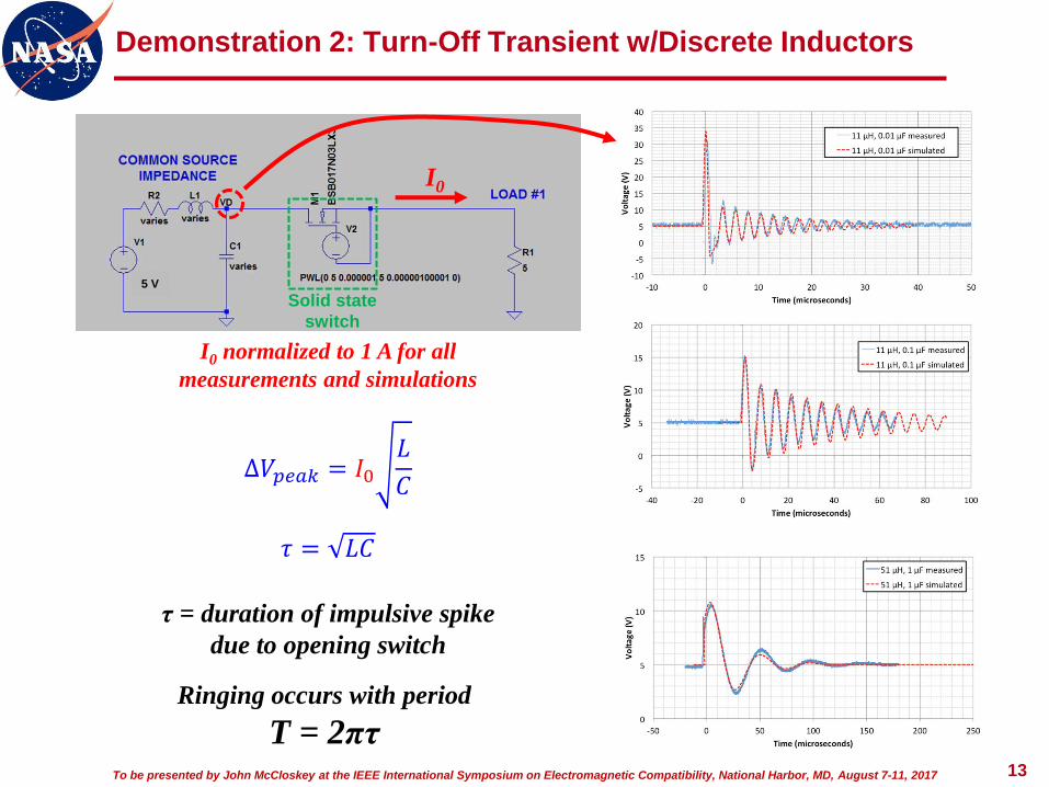
Demonstration 2: Turn-Off Transient w/Discrete Inductors
∆𝑉𝑝𝑒𝑎𝑘 = 𝐼0𝐿
𝐶
I0 normalized to 1 A for all
measurements and simulations
𝜏 = 𝐿𝐶
I0
5 V
Ringing occurs with period
T = 2πτ
τ = duration of impulsive spike
due to opening switch
Solid state
switch
Page 14
14To be presented by John McCloskey at the IEEE International Symposium on Electromagnetic Compatibility, National Harbor, MD, August 7-11, 2017
How about a real cable?
Previous simulations and measurements were performed using discrete components
We wanted to see if the lumped model accurately predicted the transients on actual cable
RG58 used as case study
Coax never used for power wiring
Used because of well-defined and well-controlled impedance characteristics
Used lengths of 16.8 m, 25.4 m, and 31.5 m
RG58 parameters:R/l = 51 mΩ/m
L/l = 0.25 µH/m
C/l = 100 pF/mFrequencies for transients
considered in this study
Page 15
15To be presented by John McCloskey at the IEEE International Symposium on Electromagnetic Compatibility, National Harbor, MD, August 7-11, 2017
Demonstration 3: Turn-Off Transient w/RG58 Coax
Bulk parameter model
provides good agreement
with measured results
Z0 = √(L/C) = 50 Ω
ΔVpeak independent of pulse width
τ = √(LC) = 5 nsec/m
Period = 2π√(LC)
= 31 nsec/m
Solid state
switch
Page 16
16To be presented by John McCloskey at the IEEE International Symposium on Electromagnetic Compatibility, National Harbor, MD, August 7-11, 2017
Typical Transients on Spacecraft
Now that we have established confidence in our models, we can extrapolate
them to predict typical transients on spacecraft
Recall typical power wiring characteristics
(+) and (-) bundles separated by 10s of cm
~1 meter from battery to distribution point
Parameters
• R = 3 mΩ
• L = 1 µH
• C = 10 pF
• Z0 = 350 Ω
We can plug these values into our models...
Page 17
17To be presented by John McCloskey at the IEEE International Symposium on Electromagnetic Compatibility, National Harbor, MD, August 7-11, 2017
Turn-On Transient: Typical
Representative
Turn-On Transient
Circuit Model
~10 µsec
ΔVpeak = bus potential
(pulled to 0 V;
does not go negative)
Solid state
switch
Page 18
18To be presented by John McCloskey at the IEEE International Symposium on Electromagnetic Compatibility, National Harbor, MD, August 7-11, 2017
CS06 Negative (-) Pulse
Tailored CS06 (-) pulse good representation for turn-off transient
10 µsec pulse width
Magnitude
• Tailor to equal line potential to pull bus to 0 V (no lower)
• MIL-STD-461A default is lesser of 2x line voltage or 100 V
• WILL pull the bus negative; not desired
0
E
t
TIME (microseconds)
VO
LTA
GE
E = 2x line voltage or 100 V, whichever is less
t = 10 µsec
Page 19
19To be presented by John McCloskey at the IEEE International Symposium on Electromagnetic Compatibility, National Harbor, MD, August 7-11, 2017
Turn-Off Transient: Typical (open circuit)
Representative
Turn-Off Transient
Circuit Model
ΔVpeak > 200 V
for I0 = 1 A
Pulse width ≈ 10 nsec
Solid state
switch
Page 20
20To be presented by John McCloskey at the IEEE International Symposium on Electromagnetic Compatibility, National Harbor, MD, August 7-11, 2017
Turn-Off Transient With Filter at Distribution Point
0.0µs 0.2µs 0.4µs 0.6µs 0.8µs 1.0µs 1.2µs 1.4µs 1.6µs 1.8µs 2.0µs 2.2µs 2.4µs 2.6µs 2.8µs
29.9V
30.0V
30.1V
30.2VV(vd)
Representative Turn-Off
Transient Model With Filter
in Power Distribution Unit
(PDU) or equivalent
Transient at
distribution point
ΔV ≈ 0.1 VTransient easily “snubbed”
with additional capacitance
at distribution point
Solid state
switch
Page 21
21To be presented by John McCloskey at the IEEE International Symposium on Electromagnetic Compatibility, National Harbor, MD, August 7-11, 2017
CS06 Positive (+) Pulse
CS06 (+) pulse NOT good representation for turn-on transient
Magnitude: tailorable; not really an issue
10 µsec pulse width much longer than that of typical transients
Source impedance < 1 ohm; much lower than that of typical transients (not as
easily “snubbed”)
0
E
t
TIME (microseconds)
VO
LTA
GE
E = 2x line voltage or 100 V, whichever is less
t = 10 µsec
Page 22
22To be presented by John McCloskey at the IEEE International Symposium on Electromagnetic Compatibility, National Harbor, MD, August 7-11, 2017
Let’s Return to Our Turn-On Transient Model…
Representative Turn-On
Transient Model With Filter
in Power Distribution Unit
(PDU) or equivalent
Transient at
distribution point
ΔV < 1 V
Solid state
switch
Page 23
23To be presented by John McCloskey at the IEEE International Symposium on Electromagnetic Compatibility, National Harbor, MD, August 7-11, 2017
Summary
Turn-off transients do not pose significant problem on most spacecraft
Open-circuit potential can be high, but very short duration
Easily “snubbed” with modest amount of capacitance on load input filters or at
distribution point
Eliminated with large filter capacitor at distribution point (if used)
CS06 positive-going pulse need not be applied
Even if open-circuit large magnitude, short duration turn-off transient were considered
real, Javor showed in [3] that it poses no threat to input filter components
On any spacecraft platform, an analysis of the power subsystem should be
performed as early as possible in order to determine the worst-case magnitudes of
turn-on and turn-off transients that may be observed at the point of distribution
If these magnitudes are determined to be sufficiently benign, i.e. on the order of 3 V
or less, then CS06 negative-going pulse need not be applied either
Any concerns sufficiently covered by GEVS tailoring of CS101 and CS114 as below:
CS101, 1 Vrms (2.8 V peak-to-peak) from 30 Hz to 150 kHz
CS114, effective limit of 1 Vrms (20 mA into 50 Ω) from 150 kHz to 50 MHz
Page 24
24To be presented by John McCloskey at the IEEE International Symposium on Electromagnetic Compatibility, National Harbor, MD, August 7-11, 2017
References
[1] K. Javor, “Specifying Control of Immunity to Power Line Switching
Transients,” 1994 IEEE EMC Symposium, Chicago
[2] K. Javor, “Specification, Measurement, and Control of Electrical Switching
Transients,” NASA/CR-1999-209574, NASA Marshall Space Flight Center,
AL 35812, September 1999
[3] K. Javor “Investigation Into the Effects of Microsecond Power Line
Transients on Line-Connected Capacitors” NASA/CR-2000-209906, NASA
Marshall Space Flight Center, AL 35812, February 2000
Page 25
25To be presented by John McCloskey at the IEEE International Symposium on Electromagnetic Compatibility, National Harbor, MD, August 7-11, 2017
THANK YOU!
Page 26
26To be presented by John McCloskey at the IEEE International Symposium on Electromagnetic Compatibility, National Harbor, MD, August 7-11, 2017
Backup
Page 27
27To be presented by John McCloskey at the IEEE International Symposium on Electromagnetic Compatibility, National Harbor, MD, August 7-11, 2017
A Proper Switch
Proper testing of transients requires:
Bounce-less, arc-less switch
Repeatable rise times that are fast (short) compared to circuit response
Switching
FET
Contact
de-bouncing
circuit