P JINST Hardware Demonstrator of a Compact First-Level Muon Track Trigger for Future Hadron Collider Experiments D. Cieri, a, 1 S. Abovyan, a V. Danielyan, a M. Fras, a P. Gadow, a O. Kortner, a S. Kortner, a H. Kroha, a F. Müller, a S. Nowak, a P. Richter a and K. Schmidt-Sommerfeld a a Max-Planck-Institut für Physik Föhringer Ring 6, 80805 Munich, Germany E-mail: [email protected]A: Single muon triggers are crucial for the physics programmes at hadron collider experi- ments. To be sensitive to electroweak processes, single muon triggers with transverse momentum thresholds down to 20 GeV and dimuon triggers with even lower thresholds are required. In order to keep the rates of these triggers at an acceptable level these triggers have to be highly selective, i.e. they must have small accidental trigger rates and sharp trigger turn-on curves. The muon systems of the LHC experiments and experiments at future colliders like FCC-hh will use two muon chamber systems for the muon trigger, fast trigger chambers like RPCs with coarse spatial resolution and much slower precision chambers like drift-tube chambers with high spatial resolution. The data of the trigger chambers are used to identify the bunch crossing in which the muon was created and for a rough momentum measurement while the precise measurements of the muon trajectory by the precision chambers are ideal for an accurate muon momentum measurement. A compact muon track finding algorithm is presented, where muon track candidates are reconstructed using a binning algorithm based on a 1D Hough Transform. The algorithm has been designed and implemented on a System-On-Chip device. A hardware demonstration using Xilinx Evaluation boards ZC706 has been set-up to prove the concept. The system has demonstrated the feasibility to reconstruct muon tracks with a good angular resolution, whilst satisfying latency constraints. The demonstrated track-reconstruction system, the chosen architecture, the achievements to date and future options for such a system will be discussed. K: Trigger algorithms, Trigger concepts and systems, Digital electronic circuits, Pattern recognition, cluster finding, calibration and fitting methods, Wire chambers 1Corresponding author. arXiv:1902.04122v1 [physics.ins-det] 11 Feb 2019
Transcript
Prepared for submission to JINST
Hardware Demonstrator of a Compact First-Level MuonTrack Trigger for Future Hadron Collider Experiments
D. Cieri,a,1 S. Abovyan,a V. Danielyan,a M. Fras,a P. Gadow,a O. Kortner,a S. Kortner,a H.Kroha,a F. Müller,a S. Nowak,a P. Richtera and K. Schmidt-Sommerfelda
aMax-Planck-Institut für PhysikFöhringer Ring 6, 80805 Munich, Germany
Abstract: Single muon triggers are crucial for the physics programmes at hadron collider experi-ments. To be sensitive to electroweak processes, single muon triggers with transverse momentumthresholds down to 20 GeV and dimuon triggers with even lower thresholds are required.
In order to keep the rates of these triggers at an acceptable level these triggers have to behighly selective, i.e. they must have small accidental trigger rates and sharp trigger turn-on curves.The muon systems of the LHC experiments and experiments at future colliders like FCC-hh willuse two muon chamber systems for the muon trigger, fast trigger chambers like RPCs with coarsespatial resolution and much slower precision chambers like drift-tube chambers with high spatialresolution.
The data of the trigger chambers are used to identify the bunch crossing in which the muonwas created and for a rough momentum measurement while the precise measurements of the muontrajectory by the precision chambers are ideal for an accurate muon momentum measurement.
A compact muon track finding algorithm is presented, where muon track candidates arereconstructed using a binning algorithm based on a 1D Hough Transform. The algorithm has beendesigned and implemented on a System-On-Chip device. A hardware demonstration using XilinxEvaluation boards ZC706 has been set-up to prove the concept.
The system has demonstrated the feasibility to reconstruct muon tracks with a good angularresolution, whilst satisfying latency constraints. The demonstrated track-reconstruction system, thechosen architecture, the achievements to date and future options for such a system will be discussed.
Keywords: Trigger algorithms, Trigger concepts and systems, Digital electronic circuits, Patternrecognition, cluster finding, calibration and fitting methods, Wire chambers
3 A Compact L1 Muon Track Finder Processor 33.1 Segment Finder with a 1D Hough Transform 33.2 Segment Fitter with a Simple Linear Regression Technique 73.3 Transverse Momentum Calculation 7
The exceptional results obtained by the Large Hadron Collider (LHC) [1] at CERN are pushingtowards the development and the design of next-generation hadron colliders. CERN has alreadyplanned to upgrade the LHC to the High-Luminosity LHC in order to reach a luminosity up to oneorder of magnitude higher than the nominal design [2]. In addition to that, studies have begun for aconceptual design of a Future Circular Collider (FCC) with a centre-of-mass energy
√s = 100TeV
[3].Experiments at future colliders will have to operate in a very harsh radiation environment and
with high detector occupancies. The physics programme of these experiments will still be focusedon the understanding of the electro-weak symmetry breaking mechanism and on the search ofBeyond Standard Model physics signals.
Selective muon triggers will still be crucial to undertake this ambitious physics programme.The foreseen high luminosities will require highly selective first-level (L1) muon triggers in orderto obtain the output trigger rate within acceptable rates. This can be done by improving the spatialresolution of the triggering system, resulting in a drastically sharpened turn-on curve of the L1trigger efficiency with respect to the muon transverse momentum pT .
– 1 –
2 First-Level Muon Triggers at future colliders
A typical muon detector system at high energy hadron collider physics experiment is composedof two kinds of gas detectors. Fast gaseous detectors, e.g. Resistive Plate Chambers (RPCs) orThin Gap Chambers (TGCs), which have an excellent time resolution (better than 20 ns), ideal toidentify the bunch crossing in which the muons have been produced; and high-resolution detectors,like cylindrical Drift Tubes (DTs) that provide more precise measurements of the muon positions.
Three possible arrangements for the muon chambers have been taken into account in this paper.
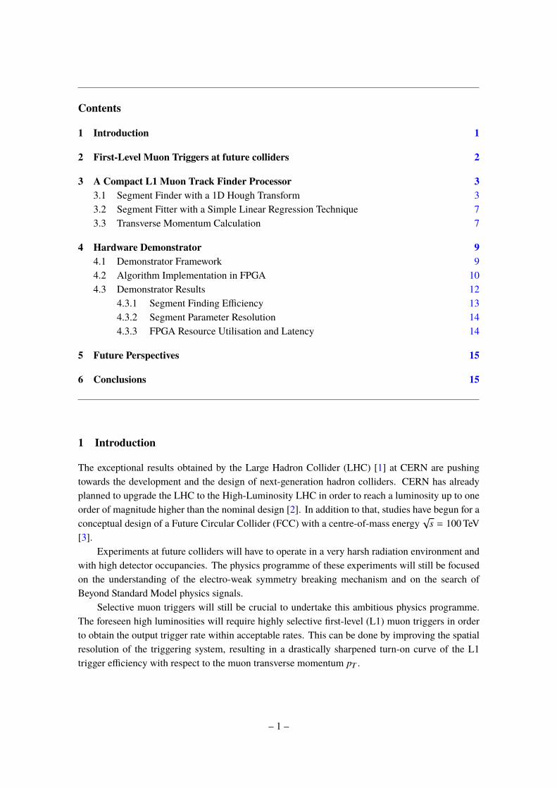
• ATLASMuon Barrel (Figure 1). The system is composed of three layers of muon chambersimmersed in a magnetic field and disposed at distance of the order of few meters. Eachchamber (CHB1, CHB2, CHB3) is composed of two multi-layers (ML1, ML2) of DTs,surrounded by fast RPC devices. Reconstructing the track segments in the different chambers,it is possible to calculate the deviation angle or the sagitta of the muon track and, eventually,to compute the muon transverse momentum.
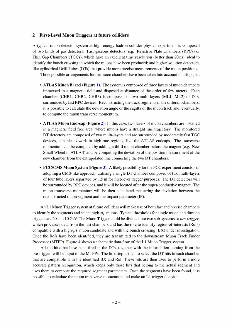
• ATLAS Muon End-cap (Figure 2). In this case, two layers of muon chambers are installedin a magnetic field free area, where muons have a straight line trajectory. The monitoredDT detectors are composed of two multi-layers and are surrounded by moderately fast TGCdevices, capable to work in high-rate regions, like the ATLAS endcaps. The transversemomentum can be computed by adding a third muon chamber before the magnet (e.g. NewSmall Wheel in ATLAS) and by computing the deviation of the position measurement of thenew chamber from the extrapolated line connecting the two DT chambers.
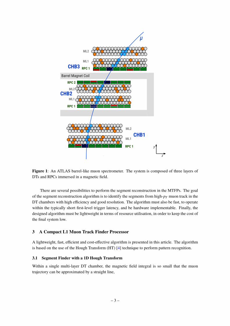
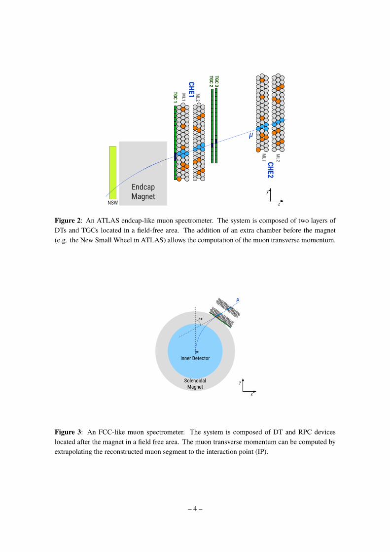
• FCC/CMSMuon System (Figure 3). A likely possibility for the FCC experiment consists ofadopting a CMS-like approach, utilising a single DT chamber composed of two multi-layersof four tube layers separated by 1.5m for first-level trigger purposes. The DT detectors willbe surrounded by RPC devices, and it will be located after the super-conductive magnet. Themuon transverse momentum will be then calculated measuring the deviation between thereconstructed muon segment and the impact parameter (IP).
An L1Muon Trigger system at future colliders will make use of both fast and precise chambersto identify the segments and select high-pT muons. Typical thresholds for single muon and dimuontriggers are 20 and 10GeV. TheMuon Trigger could be divided into two sub-systems: a pre-trigger,which processes data from the fast chambers and has the role to identify region-of-interests (RoIs)compatible with a high-pT muon candidate and with the bunch crossing (BX) under investigation.Once the RoIs have been identified, they are transmitted to the downstream Muon Track FinderProcessor (MTFP). Figure 4 shows a schematic data-flow of the L1 Muon Trigger system.
All the hits that have been fired in the DTs, together with the information coming from thepre-trigger, will be input to the MTFPs. The first step is then to select the DT hits in each chamberthat are compatible with the identified BX and RoI. These hits are then used to perform a moreaccurate pattern recognition, which keeps only those hits that belong to the actual segment anduses them to compute the required segment parameters. Once the segments have been found, it ispossible to calculate the muon transverse momentum and make an L1 trigger decision.
– 2 –
RPC 1
RPC 1
RPC 2
RPC 1
ML1
ML2
ML1
ML2
ML1
ML2
CHB1
CHB2
CHB3Barrel Magnet Coil
μ
z
y
Figure 1: An ATLAS barrel-like muon spectrometer. The system is composed of three layers ofDTs and RPCs immersed in a magnetic field.
There are several possibilities to perform the segment reconstruction in the MTFPs. The goalof the segment reconstruction algorithm is to identify the segments from high-pT muon track in theDT chambers with high efficiency and good resolution. The algorithm must also be fast, to operatewithin the typically short first-level trigger latency, and be hardware implementable. Finally, thedesigned algorithm must be lightweight in terms of resource utilisation, in order to keep the cost ofthe final system low.
3 A Compact L1 Muon Track Finder Processor
A lightweight, fast, efficient and cost-effective algorithm is presented in this article. The algorithmis based on the use of the Hough Transform (HT) [4] technique to perform pattern recognition.
3.1 Segment Finder with a 1D Hough Transform
Within a single multi-layer DT chamber, the magnetic field integral is so small that the muontrajectory can be approximated by a straight line,
– 3 –
Endcap Magnet
TGC 1
ML1
ML2
CHE1
μ
NSW z
y
TGC 2TGC 3
CHE2M
L1
ML2
Figure 2: An ATLAS endcap-like muon spectrometer. The system is composed of two layers ofDTs and TGCs located in a field-free area. The addition of an extra chamber before the magnet(e.g. the New Small Wheel in ATLAS) allows the computation of the muon transverse momentum.
μ
IP
ΔΦ
Inner Detector
Solenoidal Magnet
x
y
Figure 3: An FCC-like muon spectrometer. The system is composed of DT and RPC deviceslocated after the magnet in a field free area. The muon transverse momentum can be computed byextrapolating the reconstructed muon segment to the interaction point (IP).
– 4 –
FRONT END ELECTRONICS
BACK END ELECTRONICS
Pre-TriggerRPC Hits
DT Hits DT Hit Buffer
DT Hit Matcher
RoI, BX Input Seed
Muon Track Finder Processor
Segment Finders
Matched DT Hits
pT Calculator
to DAQ
to L1 Trigger
Segments
Figure 4: Diagram of a possible readout chain for a muon trigger sector. RPCs hits are transmittedfirst to a pre-trigger processor, which identify the RoI and BX and computes a coarse estimation ofthe segment parameters. Meanwhile, DT hits are transmitted to the Muon Track Finder Processors,where they are matched with the pre-trigger windows and then used to perform a more precisesegment reconstruction. The muon transverse momentum is then computed and the result isforward to the L1 Global Trigger for a final decision.
y = mz + b, (3.1)
where (z, y) are the local coordinates of the muon in the chamber at each time, and (m, b) are theslope-intercept parameters of the segment. A Hough Transform considers a straight line in termsof its slope-intercept parameter. Each point on the track draws a straight line in the HT space. Acrossing of lines in the HT space identifies the (m, b) parameters corresponding to a possible trackcandidate.
Each fired drift tube in the DT chamber measures the drift radius r , corresponding to thedistance between the tube anode (zt, yt ) and the muon track,
r =mzt + b + yt√
1 + m2. (3.2)
In addition to the RoI information, the pre-trigger could be used also to compute a first estimateof the segment parameters (m̄, b̄) that can be used as input seed by the segment finder algorithm.Indeed a 1D HT array can be constructed, where the m-axis reduces to the point m = m̄. Sincethe two MLs are supposed to be at a distance of the order of 20 tube diameters, it is reasonable toconsider them independents and to have a histogram for each ML.
For each DT hit a value of the intercept b is calculated,
– 5 –
b y
z
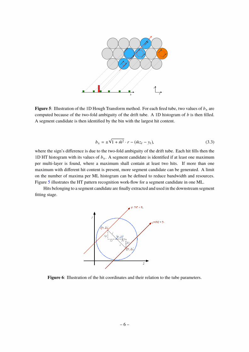
Figure 5: Illustration of the 1D Hough Transform method. For each fired tube, two values of b± arecomputed because of the two-fold ambiguity of the drift tube. A 1D histogram of b is then filled.A segment candidate is then identified by the bin with the largest hit content.
b± = ±√
1 + m̄2 · r − (m̄zt − yt ), (3.3)
where the sign’s difference is due to the two-fold ambiguity of the drift tube. Each hit fills then the1D HT histogram with its values of b±. A segment candidate is identified if at least one maximumper multi-layer is found, where a maximum shall contain at least two hits. If more than onemaximum with different hit content is present, more segment candidate can be generated. A limiton the number of maxima per ML histogram can be defined to reduce bandwidth and resources.Figure 5 illustrates the HT pattern recognition work-flow for a segment candidate in one ML.
Hits belonging to a segment candidate are finally extracted and used in the downstream segmentfitting stage.
Figure 6: Illustration of the hit coordinates and their relation to the tube parameters.
– 6 –
3.2 Segment Fitter with a Simple Linear Regression Technique
In the case where there is no magnetic field within a chamber or the field integral is small, the muontrajectory in a chamber can be treated as a straight line. In this case, the segment parameters arecalculated by means of a Simple Linear Regression (SLR) fitter.
Once the segment candidate hits have been identified, it is possible to compute the exact hitpositions on the segment,
yh = yt ± ∆y, zh = zt ∓ ∆z, (3.4)
where the signs of ∆y, ∆z depend on the which solution of b± is compatible with the investigatedsegment candidate. Figure 6 shows a scheme of the utilised coordinates for a single tube.∆y and ∆z can be calculated by means of simple trigonometric rules that express them in terms
of m̄,
∆y =r
√1 + m̄2
, ∆z = r · m̄√
1 + m̄2. (3.5)
Once the hit coordinate have been calculated, it is finally possible to compute the segment fitparameters using the standard linear regression formulas,
b̂ =(∑h yh)(
∑h z2
h) − (∑h zhyh)(
∑h zh)
nHits(∑
h z2h) − (∑h zh)2
, (3.6)
m̂ =nHits(
∑h zhyh) − (
∑h yh)(
∑h zh)
nHits(∑
h z2h) − (∑h zh)2
, (3.7)
where nHits is the number of hits in the current segment candidate.In the case that more than one segment has been reconstructed, the algorithm can set-up in
different ways. For single muon triggers, it keeps only the segment with the lowest fit χ2, while fora dimuon trigger it would keep the two segments with the lowest χ2 values. In principle, a cut onthe χ2 could be also be imposed to reject fake segments.
Segments are reconstructed independently in the three muon chambers and then used for thefinal pT computation.
3.3 Transverse Momentum Calculation
Different strategies can be used to compute the muon transverse momentum, depending on thenumber of measured positions in the detector. The transverse momentum of a muon particle withcharge q travelling in a homogeneous magnetic field of magnitude B is defined as,
pT = qBR, (3.8)
where R is the curvature radius R. Different methods can be adopted to measure R, depending onthe number of available position measurements in the detector.
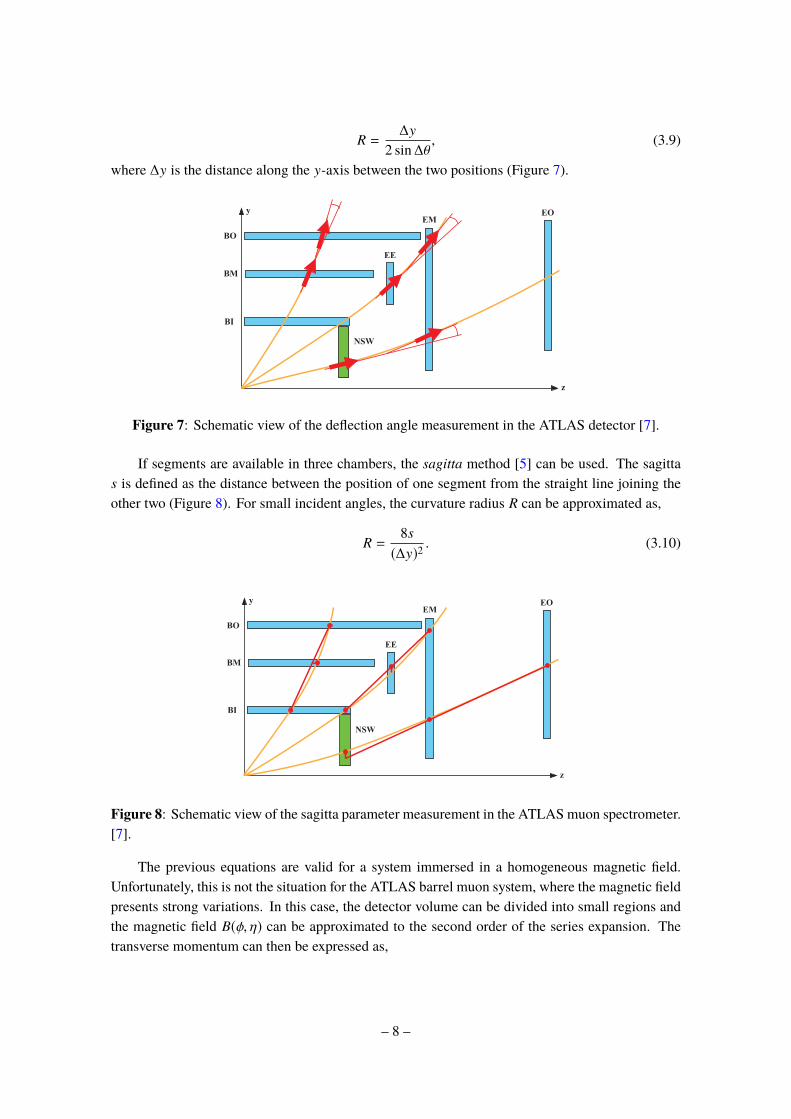
If only two measurements are available, the curvature radius can be calculated by measuringthe deflection angle ∆θ, defined as the polar-angle difference between segments in two chambers.
– 7 –
R =∆y
2 sin∆θ, (3.9)
where ∆y is the distance along the y-axis between the two positions (Figure 7).
Not
revi
ewed
,for
inte
rnal
circ
ulat
ion
only
8.6.2 Trigger Performance
y
z
BO
BM
BI
NSW
EE
EMEO
(a) Two-stations: deflection angle
y
z
BO
BM
BI
NSW
EE
EMEO
(b) Three-stations: sagitta
Figure 8.25: (a) Schematic of the concept of the polar angle difference between the two segments. Thecombination considered for the barrel is the middle and outer stations, but any other combinationcan in principle be used as well. (b) Schematic of the concept of the distance between the positionof a segment and the position extrapolated from two segments. The figures show the cross-sectionalview for so-called even sectors. The variable is defined similarly in so-called odd sectors. For 1.05 <|h| < 1.3, the endcap inner station is assumed alternatively to the barrel inner station.
211
Figure 7: Schematic view of the deflection angle measurement in the ATLAS detector [7].
If segments are available in three chambers, the sagitta method [5] can be used. The sagittas is defined as the distance between the position of one segment from the straight line joining theother two (Figure 8). For small incident angles, the curvature radius R can be approximated as,
R =8s(∆y)2
. (3.10)
Not
revi
ewed
,for
inte
rnal
circ
ulat
ion
only
8.6.2 Trigger Performance
y
z
BO
BM
BI
NSW
EE
EMEO
(a) Two-stations: deflection angle
y
z
BO
BM
BI
NSW
EE
EMEO
(b) Three-stations: sagitta
Figure 8.25: (a) Schematic of the concept of the polar angle difference between the two segments. Thecombination considered for the barrel is the middle and outer stations, but any other combinationcan in principle be used as well. (b) Schematic of the concept of the distance between the positionof a segment and the position extrapolated from two segments. The figures show the cross-sectionalview for so-called even sectors. The variable is defined similarly in so-called odd sectors. For 1.05 <|h| < 1.3, the endcap inner station is assumed alternatively to the barrel inner station.
211
Figure 8: Schematic view of the sagitta parameter measurement in the ATLASmuon spectrometer.[7].
The previous equations are valid for a system immersed in a homogeneous magnetic field.Unfortunately, this is not the situation for the ATLAS barrel muon system, where the magnetic fieldpresents strong variations. In this case, the detector volume can be divided into small regions andthe magnetic field B(φ, η) can be approximated to the second order of the series expansion. Thetransverse momentum can then be expressed as,
– 8 –
pT =q∆y2B(η, φ)
8s= S(s) + P(φ) + E(η), (3.11)
where S, P and E are simple polynomial functions,
S(s) = (1/s − a0)/a1, (3.12)
P(φ) =2∑i=0
pi · φi, (3.13)
E(η) =2∑i=0
ei · ηi, (3.14)
with ai, pi and ei parameters that can be determined numerically with experimental data.
4 Hardware Demonstrator
In order to demonstrate the feasibility of the approach and measure its performance, a full muonreconstruction at hardware trigger level in a single trigger tower (three muon chambers) have beenimplemented for the System-on-Chip (SoC) Xilinx Zynq device1, mounted on a Xilinx ZC706evaluation board [6].
The algorithm has been adapted to the geometry of the Phase II upgrade of the ATLAS muonbarrel spectrometer [7]. So, the current muon trigger system, composed by RPCs and TGCs, isused as a pre-trigger for the MTFP. MDT hits are then matched and used for the finer segmentreconstruction [8].
Figure 9 shows an overview of the MTFP, illustrating the main logic components and theirinterconnectivity. The pattern recognition and the segment fitting steps are implemented as dedi-cated IP-Core into the Programmable Logic (PL) of the device, while two different implementationsof transverse momentum computation have been investigated. A first possibility consists of per-forming the pT calculation into the Processing System (PS), where it could take advantage of thefloating-point unit (FPU) and the media processing engine (NEON) of the ARM processor. Analternative would be integrating it directly on the PL, which eliminates any further latency due todata transmissions between the PL and the PS.
4.1 Demonstrator Framework
In order to measure the performance of the implementation under realistic condition and withsufficient statistics, simulated single muon events are used as input data and are transmitted fromPC software via USB to the PS and further to the PL by using a DMA IP-Core (Direct MemoryAccess), which loads the single hit information one-by-one into the trigger IP-Core. After trackreconstruction, the resulting data is returned to the PS and further back to the PC where the resultsare compared with simulation, see Fig. 10.
Instead of transmitting the full dataset via USB, one could consider to store input data in the PSmemory and, therefore, minimize implementation effort. As the PS memory provides a two-level
1Xilinx xc7z045ffg900-2
– 9 –
CH 1 DT Hits
FIFO
CH 2 DT Hits
FIFO
CH 3 DT Hits
FIFO
CH 1 Segment
Finder
CH 2 Segment
Finder
CH 3 Segment
Finder
Programmable Logic (PL) Processing System (PS)
DT1 Hits
DT2 Hits
DT3 Hits
seed 3
seed 2
seed 1
segment 1
segment 2
segment 3
pT Calculator
AXI
Figure 9: Overview of the main components of the MTFP and their location on the Zynq device.DT hits from each chamber are first stored in a FIFO, waiting for the arrival of the pre-trigger seed.Once it comes, hits are transmitted to the segment finder modules, which reconstruct the threesegments. Segments are then transmitted to the PS via AXI bus where the final pT calculation takesplace. An alternative approach integrates also the pT calculation in the PL area.
Figure 10: Dataflow of the demonstrator set-up. Simulated data is transferred via USB to thedemonstrator where it is processed by the track reconstruction logic. Afterwards, the results aretransferred back to the PC where they are compared with simulation.
cache, the timing performance of this simple implementation would be sufficiently better than for arealistic implementation, because the input data is permanently stored in the cache, and, therefore,immediately available for processing.
4.2 Algorithm Implementation in FPGA
Figure 11 shows a simplified layout of the implemented segment finder firmware. The RoIs of afuture ATLAS or FCC first-level muon trigger are supposed to have a maximum width of ±3 tubes.Assuming that the tubes will be readout per tube layer, with each tube sending one hit per clock, afixed-length packet of six clock cycles is input to the firmware. The seed information is assumed to
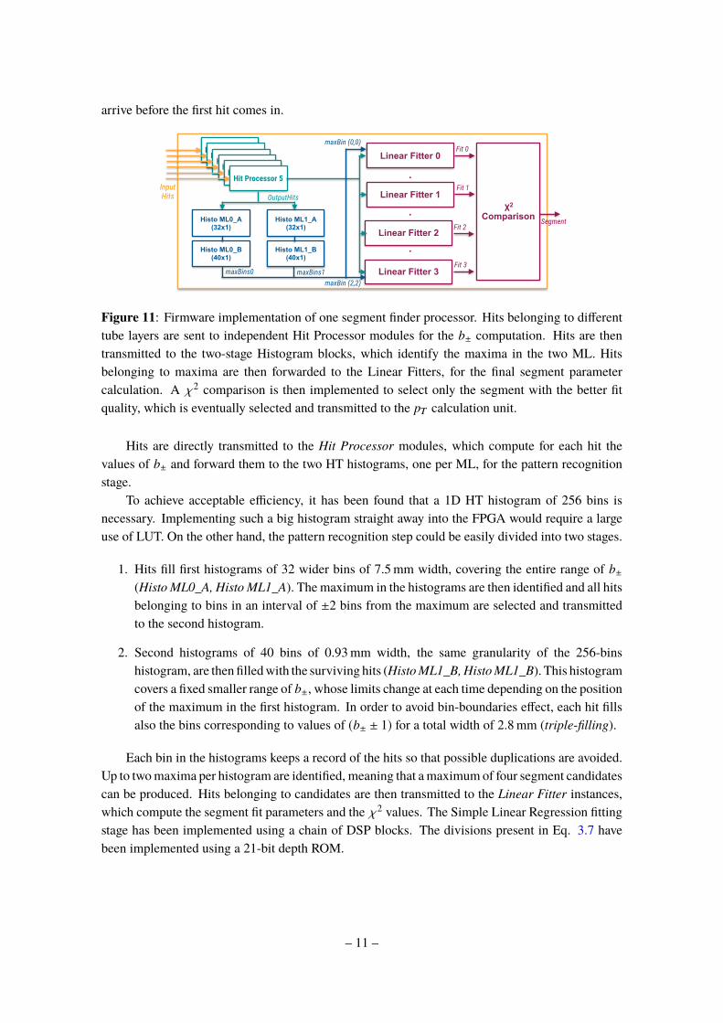
Figure 11: Firmware implementation of one segment finder processor. Hits belonging to differenttube layers are sent to independent Hit Processor modules for the b± computation. Hits are thentransmitted to the two-stage Histogram blocks, which identify the maxima in the two ML. Hitsbelonging to maxima are then forwarded to the Linear Fitters, for the final segment parametercalculation. A χ2 comparison is then implemented to select only the segment with the better fitquality, which is eventually selected and transmitted to the pT calculation unit.
Hits are directly transmitted to the Hit Processor modules, which compute for each hit thevalues of b± and forward them to the two HT histograms, one per ML, for the pattern recognitionstage.
To achieve acceptable efficiency, it has been found that a 1D HT histogram of 256 bins isnecessary. Implementing such a big histogram straight away into the FPGA would require a largeuse of LUT. On the other hand, the pattern recognition step could be easily divided into two stages.
1. Hits fill first histograms of 32 wider bins of 7.5mm width, covering the entire range of b±(Histo ML0_A, Histo ML1_A). The maximum in the histograms are then identified and all hitsbelonging to bins in an interval of ±2 bins from the maximum are selected and transmittedto the second histogram.
2. Second histograms of 40 bins of 0.93mm width, the same granularity of the 256-binshistogram, are then filledwith the surviving hits (HistoML1_B,HistoML1_B). This histogramcovers a fixed smaller range of b±, whose limits change at each time depending on the positionof the maximum in the first histogram. In order to avoid bin-boundaries effect, each hit fillsalso the bins corresponding to values of (b± ± 1) for a total width of 2.8mm (triple-filling).
Each bin in the histograms keeps a record of the hits so that possible duplications are avoided.Up to twomaxima per histogram are identified, meaning that amaximum of four segment candidatescan be produced. Hits belonging to candidates are then transmitted to the Linear Fitter instances,which compute the segment fit parameters and the χ2 values. The Simple Linear Regression fittingstage has been implemented using a chain of DSP blocks. The divisions present in Eq. 3.7 havebeen implemented using a 21-bit depth ROM.
– 11 –
The implemented algorithm has been designed for a single muon trigger. For this reason,produced segments are compared in the χ2 comparison module, which selects the segment withthe lowest χ2 and transmits it to the pT calculation unit.
4.3 Demonstrator Results
To validate the implemented algorithm, simulated physics events of single muons were producedwith standalone simulation software, including modelling of the ATLAS Phase-II MDT chambersand of the expected background hit rate at HL-LHC. For these studies only the more difficult caseof the ATLAS Muon Barrel spectrometer has been considered, where the provided input seed hasan average angular resolution of the order of the 10-15mrad.
An emulation software has been developed, processing the same digitised hit and seed infor-mation used as input to the demonstrator to reconstruct segments. Hit and seed data are transmittedto the evaluation board over USB-UART and output segments are read out in the same way. A com-parison software has also been created, comparing the results obtained in hardware and emulation.Since the developed emulator code is not clock-accurate in the description of the algorithm, smalldifferences are expected to arise.
recoα
0.2−0.1−00.10.20.30.40.5N
o. S
egm
ents
0
50
100
150
200
250hardware
emulation
Compact Segment Finder Demonstrator, ATLAS Phase-2
recoα 0.2− 0.1− 0 0.1 0.2 0.3 0.4 0.5
ratio
hw
/em
0.80.9
11.11.2
(a)
reco b
100− 80−60−40−20−020406080100N
o. S
egm
ents
0
100
200
300
400
500
600
hardware
emulation
Compact Segment Finder Demonstrator, ATLAS Phase-2
reco b100− 80− 60− 40− 20− 0 20 40 60 80 100
ratio
hw
/em
0.80.9
11.11.2
(b)
Figure 12: Distribution of segment candidate as a function of the fitted segment parameters(α, b). Results obtained with the hardware demonstrator (dots) are compared with expectationsfrom software emulation (blue line). A compatibility of 99.7% has been observed, with a perfectmatching of about 99.5%.
Figure 12 shows the distributions of the reconstructed segment parameters in both hardwareand emulation. The hardware is able to reconstruct about 99.7% of the segments found by theemulation and in about 99.5% of the cases, hardware and emulation create the same segment, withidentical angular and spatial parameters.
– 12 –
4.3.1 Segment Finding Efficiency
The segment finding efficiency is measured with respect to all generatedmuon particles that produceat least two hits in each MDT multi-layer. According to the ATLAS Phase-II requirements [7], amuon segment is defined as correctly reconstructed if,
where α is the angle between the segment and the z-axis. Figure 13a shows the segment findingefficiency as a function of the input seed accuracy, as measured in hardware and emulation. Bothimplementations produce similar results, although the hardware shows a slightly lower efficiency.This discrepancy is attributable to still present differences in the two implementations, which areforeseen to be fixed in future.
Compact Segment Finder Demonstrator, ATLAS Phase-2
(b)
Figure 13: Segment Finding efficiency as a function of the input seed accuracy. (a) Results obtainedwith the hardware demonstrator (red) are comparedwith expectations from software emulation (blueline). A good agreement is observed. (b) Simulated results obtained using a reseeding procedurein case of bad input hits. For reference results obtained without the reseeding are also shown. Thereseeding procedure significantly improves the segment finding performance.
As expected the algorithm depends strongly on the input seed accuracy. A bad input seed withuncertainty larger than 25mrad can lead to a wrong filling of the HT array and, eventually, to awrong selection of the hits for the final segment fitting. In any case, this situation is not realisticsince the ATLAS RPCs are expected to provide an input seed with an angular resolution of about20mrad in the worst case and the ATLAS TGCs have an even better resolution of the order of5mrad.
Nevertheless, in case of a very bad seed or in the most pessimistic situation, where the pre-trigger is capable to provide only a RoI without seed parameters, a reseeding procedure can beadopted to retrieve this loss in efficiency. A simple way to recompute the input seed would be touse the average positions of the hits in the two MDT multi-layers and calculate the input slope bydrawing a line between the two points.
– 13 –
Figure 13b shows the segment finding efficiency measured in emulation, with and without thereseeding. The reseeding procedure is able to compensate for the bad input seed accuracy, bringingthe efficiency above 93%. This simple reseeding procedure could be easily implemented on FPGA,with an estimated extra latency of twenty clock cycles (about 84 ns at 240MHz).
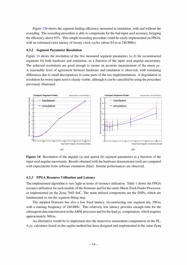
4.3.2 Segment Parameter Resolution
Figure 14 shows the resolution of the two measured segment parameters (α, b) for reconstructedsegments for both hardware and emulation, as a function of the input seed angular uncertainty.The achieved resolutions are good enough to ensure an accurate measurement of the muon pT .A reasonable level of agreement between hardware and emulation is observed, with remainingdifferences due to small discrepancies in some parts of the two implementations. A degradation inresolution for worse input seed is clearly visible, although it can be cancelled by using the procedurepreviously illustrated.
Compact Segment Finder Demonstrator, ATLAS Phase-2
(b)
Figure 14: Resolution of the angular (a) and spatial (b) segment parameters as a function of theinput seed angular uncertainty. Results obtained with the hardware demonstrator (red) are comparedwith expectations from software emulation (blue). Similar performances are observed.
4.3.3 FPGA Resource Utilisation and Latency
The implemented algorithm is very light in terms of resource utilisation. Table 1 shows the FPGAresource utilisation for each module of the firmware and for the entire Muon Track Finder Processor,as implemented on the Zynq 7045 SoC. The main utilised components are the DSPs, which arefundamental to run the segment fitting step.
The adopted firmware has also a low fixed latency, reconstructing one segment any 300 nswith a running frequency of 240MHz. This relatively low latency provides enough time for thesubsequent data transmission to the ARMprocessor and for the final pT computation, which requiresapproximately 360 ns.
An alternative would be to implement also the transverse momentum computation on the PL.A pT calculator based on the sagitta method has been designed and implemented in the same Zynq
– 14 –
Table 1: Resource utilisation of the full Muon Track Finder processor and of the single firmwaremodules, as implemented in the Xilinx Zynq XC77045 SoC device. BRAMmemory is used for theimplementation of the DT Hit FIFOs. For comparison, also available logic resources of the XilinxZynq XC77045 and XC77100 are shown.
7045 SoC device. The implemented module has a fully pipelined design and is very lightweight interms of resource usage (see Table 1). The main utilised components are the DSPs for the equationsand the BRAM, which stores the needed constants. The firmware has also a low-latency, requiringonly seven clock cycles (ca. 30 ns at 240MHz) to determine the muon transverse momentum.
5 Future Perspectives
Although a system based on Zynq 7045 devices could be able to perform successfully the muontrack finding task in a single trigger sector, it would be beneficial to adopt a slightly bigger chip.A better choice is given by the Xilinx Zynq XC7Z100, which has more than twice the number ofDSP slices than the 7045. That would allow the implementation of the other three segment findermodules and, therefore, the reconstruction of another muon track.
Further studies and improvements are also foreseen regarding the muon transverse momentumcomputation step, with a final decision to be taken on which implementation (FPGA or ARM) toadopt.
A prototype board based on Zynq/Kintex Ultrascale devices is under development within theATLAS Phase-II MDT Trigger project, and it will be used to test the feasibility and the performanceof a dimuon track finder processor.
6 Conclusions
A compact algorithm for muon track reconstruction at future hadron collider experiments has beenpresented. The algorithm has been successfully tested by means of software emulation and ahardware demonstration. The algorithm is based on a 1D Hough Transform method to perform thepattern recognition and on a Simple Linear Regression technique for the segment fitting.
– 15 –
The hardware demonstrator has successfully shown that it is possible to perform a full muontrack reconstruction in a trigger sector composed of three muon chambers with good performanceand low latency. The implemented algorithm is characterised by a low usage of FPGA resourcesand, therefore, it is an ideal candidate for hadron collider experiment purposes, where the large areaof the system places stringent requirements also on the final costs.
References
[1] L. Evans and P. Bryant, LHC Machine, JINST 3 (2008) S08001, doi:10.1088/1748-0221/3/08/S08001
[2] Burkhard Schmidt, The High-Luminosity upgrade of the LHC: Physics and Technology Challengesfor the Accelerator and the Experiments, J. Phys. : Conf. Ser. 706.2 (2016), 022002. 42 p.
[3] M. Kramer, The update of the European strategy for particle physics, Phys. Scr. 14019 (2013)
[4] H.P.V. C.Method and means for recognizing complex patterns, US Patent 3,069,654. (1962)
[5] P. Gadow, Development of a Concept for the Muon Trigger of the ATLAS Detector at the HL-LHC ,(2016) CERN-THESIS-2016-056
[6] Xilinx, Zynq-7000 All Programmable SoC Data Sheet: Overview (2017)
[7] The ATLAS Collaboration, ATLAS Trigger and Data Acquisition Phase-II Upgrade Technical DesignReport, Tech. Rep. (2017) CERN-LHCC-2017-020; ATLAS-TDR-029https://cds.cern.ch/record/2285584.
[8] S. Abovyan et al., Hardware Implementation of a Fast Algorithm for the Reconstruction of MuonTracks in ATLAS Muon Drift-Tube Chambers for the First-Level Muon Trigger at the HL-LHC,arXiv:1803.05468