36
BTS3911E Hardware Description Issue 08 Date 2019-01-07 HUAWEI TECHNOLOGIES CO., LTD.

BTS3911E
Hardware Description
Issue 08
Date 2019-01-07
HUAWEI TECHNOLOGIES CO., LTD.
Copyright © Huawei Technologies Co., Ltd. 2019. All rights reserved.No part of this document may be reproduced or transmitted in any form or by any means without prior writtenconsent of Huawei Technologies Co., Ltd. Trademarks and Permissions
and other Huawei trademarks are trademarks of Huawei Technologies Co., Ltd.All other trademarks and trade names mentioned in this document are the property of their respectiveholders. NoticeThe purchased products, services and features are stipulated by the contract made between Huawei and thecustomer. All or part of the products, services and features described in this document may not be within thepurchase scope or the usage scope. Unless otherwise specified in the contract, all statements, information,and recommendations in this document are provided "AS IS" without warranties, guarantees orrepresentations of any kind, either express or implied.
The information in this document is subject to change without notice. Every effort has been made in thepreparation of this document to ensure accuracy of the contents, but all statements, information, andrecommendations in this document do not constitute a warranty of any kind, express or implied.
Huawei Technologies Co., Ltd.Address: Huawei Industrial Base
Bantian, LonggangShenzhen 518129People's Republic of China
Website: http://www.huawei.com
Email: [email protected]
Issue 08 (2019-01-07) Copyright © Huawei Technologies Co., Ltd. i
Contents
1 BTS3911E Hardware Description............................................................................................... 1
2 Changes in BTS3911E Hardware Description..........................................................................2
3 BTS3911E.........................................................................................................................................53.1 Appearance..................................................................................................................................................................... 53.2 Ports and Indicators........................................................................................................................................................ 63.3 Working Principles and Functions..................................................................................................................................9
4 BTS3911E Cables......................................................................................................................... 124.1 Cable List......................................................................................................................................................................124.2 PGND Cable................................................................................................................................................................. 144.3 Power Cable..................................................................................................................................................................144.4 FE/GE Ethernet Cable.................................................................................................................................................. 154.5 FE/GE Optical Cable.................................................................................................................................................... 174.6 Alarm Cable..................................................................................................................................................................184.7 (Optional) RF Jumper...................................................................................................................................................19
5 Auxiliary Devices........................................................................................................................ 215.1 (Optional) GPS Antenna...............................................................................................................................................215.2 (Optional) DIN-Male N-Female Connector................................................................................................................. 235.3 Optical Module............................................................................................................................................................. 23
6 Typical Networking and Cable Connection.......................................................................... 256.1 Cable Connection Principles........................................................................................................................................ 25
7 Power Requirements...................................................................................................................27
8 Engineering Specifications........................................................................................................29
BTS3911EHardware Description Contents
Issue 08 (2019-01-07) Copyright © Huawei Technologies Co., Ltd. ii
1 BTS3911E Hardware Description
IntroductionThis document describes the BTS3911E and related information, such as networking, cables,cable connections, and specifications, to provide guidelines for planning and deploying theBTS3911E.
Product VersionThe following table lists the product versions related to this document.
Product Name Solution Version Product Version
BTS3911E l SRAN12.1 and laterl RAN19.1 and laterl eRAN12.1 and later
V100R012C10 and later
Intended AudienceThis document is intended for:
l BTS3911E installation engineersl System engineersl Site maintenance engineers
Organization
BTS3911EHardware Description 1 BTS3911E Hardware Description
Issue 08 (2019-01-07) Copyright © Huawei Technologies Co., Ltd. 1

2 Changes in BTS3911E Hardware
Description
This section describes the changes in BTS3911E Hardware Description.
08 (2019-01-07)
This is the seventh commercial release.
Compared with Issue 07 (2018-10-19), this issue does not include any new information.
Compared with Issue 07 (2018-10-19), this issue includes the following change.
Topic Change Description
1 BTS3911E Hardware Description Added V100R015C10 in applicable productversions.
No information in Issue 07 (2018-10-19) is deleted from this issue.
07 (2018-10-19)
This is the seventh commercial release.
Compared with Issue 06 (2018-02-05), this issue does not include any new information.
Compared with Issue 06 (2018-02-05), this issue includes the following changes.
Topic Change Description
Ports and Indicators Added the RUN indicator description.
No information in Issue 06 (2018-02-05) is deleted from this issue.
BTS3911EHardware Description 2 Changes in BTS3911E Hardware Description
Issue 08 (2019-01-07) Copyright © Huawei Technologies Co., Ltd. 2
06 (2018-02-05)This is the sixth commercial release.
Compared with Issue 05 (2017-12-08), this issue does not include any new information.
Compared with Issue 05 (2017-12-08), this issue includes the following changes.
Topic Change Description
1 BTS3911E Hardware Description Added V100R013C10 in applicable productversions.
The following topic in Issue 05 (2017-12-08) is deleted from this issue.
l (Optional) OPM30A
05 (2017-12-08)This is the fifth commercial release.
Compared with Issue 04 (2017-08-03), this issue does not include any new information.
Compared with Issue 04 (2017-08-03), this issue includes the following changes.
Topic Change Description
(Optional) GPS Antenna Added specifications of the GPS antenna.
No information in Issue 04 (2017-08-03) is deleted from this issue.
04 (2017-08-03)This is the fourth commercial release.
Compared with Issue 03 (2017-06-30), this issue includes the following new topic:
l (Optional) OPM30A
Compared with Issue 03 (2017-06-30), this issue includes the following changes.
Topic Change Description
Ports and Indicators Modified the descriptions about the ACTindicator.
No information in Issue 03 (2017-06-30) is deleted from this issue.
03 (2017-06-30)This is the third commercial release.
BTS3911EHardware Description 2 Changes in BTS3911E Hardware Description
Issue 08 (2019-01-07) Copyright © Huawei Technologies Co., Ltd. 3
Compared with Issue 02 (2017-03-10), this issue does not include any new information.
Compared with Issue 02 (2017-03-10), this issue includes the following changes.
Topic Change Description
1 BTS3911E Hardware Description Added V100R013C00 in applicable productversions.
No information in Issue 02 (2017-03-10) is deleted from this issue.
02 (2017-03-10)
This issue is the second commercial release.
Compared with Issue 01 (2016-08-30), this issue does not include any new information.
Compared with Issue 01 (2016-08-30), this issue includes the following changes.
Topic Change Description
Ports and Indicators Added 2.1 GHz and 2.6 GHz to the TX/RXfrequency bands supported by RF ports.
No information in Issue 01 (2016-08-30) is deleted from this issue.
01 (2016-08-30)
This is the first commercial release.
Compared with Draft A (2016-06-30), this issue does not include any new information.
Compared with Draft A (2016-06-30), this issue includes the following changes.
Topic Change Description
Ports and Indicators Added the description that the port FE/GE0or FE/GE1 can provide PoE power supplyto devices connected to it.
No information in Draft A (2016-06-30) is deleted from this issue.
Draft A (2016-06-30)
This is Draft A.
BTS3911EHardware Description 2 Changes in BTS3911E Hardware Description
Issue 08 (2019-01-07) Copyright © Huawei Technologies Co., Ltd. 4
3 BTS3911E
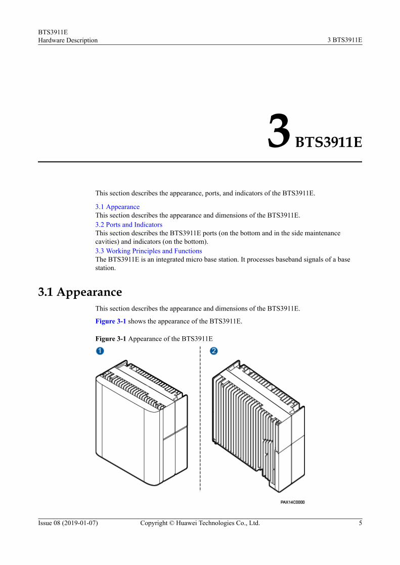
This section describes the appearance, ports, and indicators of the BTS3911E.
3.1 AppearanceThis section describes the appearance and dimensions of the BTS3911E.3.2 Ports and IndicatorsThis section describes the BTS3911E ports (on the bottom and in the side maintenancecavities) and indicators (on the bottom).3.3 Working Principles and FunctionsThe BTS3911E is an integrated micro base station. It processes baseband signals of a basestation.
3.1 AppearanceThis section describes the appearance and dimensions of the BTS3911E.
Figure 3-1 shows the appearance of the BTS3911E.
Figure 3-1 Appearance of the BTS3911E
BTS3911EHardware Description 3 BTS3911E
Issue 08 (2019-01-07) Copyright © Huawei Technologies Co., Ltd. 5

(1) BTS3911E with internal antennas (2) BTS3911E with external antennas
Figure 3-2 shows dimensions of the BTS3911E.
Figure 3-2 Dimensions of the BTS3911E
(1) BTS3911E with internal antennas (2) BTS3911E with external antennas
3.2 Ports and IndicatorsThis section describes the BTS3911E ports (on the bottom and in the side maintenancecavities) and indicators (on the bottom).
BTS3911EHardware Description 3 BTS3911E
Issue 08 (2019-01-07) Copyright © Huawei Technologies Co., Ltd. 6
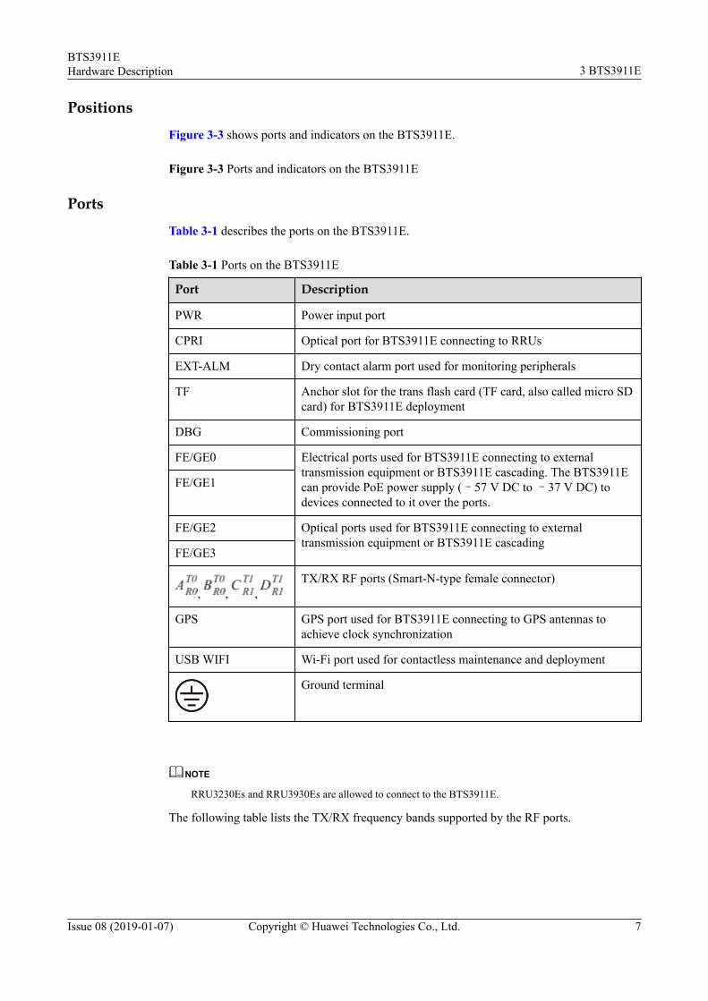
PositionsFigure 3-3 shows ports and indicators on the BTS3911E.
Figure 3-3 Ports and indicators on the BTS3911E
PortsTable 3-1 describes the ports on the BTS3911E.
Table 3-1 Ports on the BTS3911E
Port Description
PWR Power input port
CPRI Optical port for BTS3911E connecting to RRUs
EXT-ALM Dry contact alarm port used for monitoring peripherals
TF Anchor slot for the trans flash card (TF card, also called micro SDcard) for BTS3911E deployment
DBG Commissioning port
FE/GE0 Electrical ports used for BTS3911E connecting to externaltransmission equipment or BTS3911E cascading. The BTS3911Ecan provide PoE power supply (–57 V DC to –37 V DC) todevices connected to it over the ports.
FE/GE1
FE/GE2 Optical ports used for BTS3911E connecting to externaltransmission equipment or BTS3911E cascading
FE/GE3
, , , TX/RX RF ports (Smart-N-type female connector)
GPS GPS port used for BTS3911E connecting to GPS antennas toachieve clock synchronization
USB WIFI Wi-Fi port used for contactless maintenance and deployment
Ground terminal
NOTE
RRU3230Es and RRU3930Es are allowed to connect to the BTS3911E.
The following table lists the TX/RX frequency bands supported by the RF ports.
BTS3911EHardware Description 3 BTS3911E
Issue 08 (2019-01-07) Copyright © Huawei Technologies Co., Ltd. 7
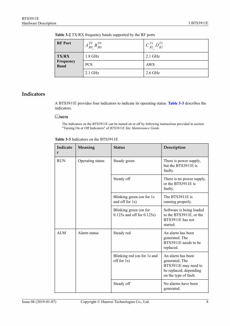
Table 3-2 TX/RX frequency bands supported by the RF ports
RF Port, ,
TX/RXFrequencyBand
1.8 GHz 2.1 GHz
PCS AWS
2.1 GHz 2.6 GHz
Indicators
A BTS3911E provides four indicators to indicate its operating status. Table 3-3 describes theindicators.
NOTE
The indicators on the BTS3911E can be turned on or off by following instructions provided in section"Turning On or Off Indicators" of BTS3911E Site Maintenance Guide.
Table 3-3 Indicators on the BTS3911E
Indicator
Meaning Status Description
RUN Operating status Steady green There is power supply,but the BTS3911E isfaulty.
Steady off There is no power supply,or the BTS3911E isfaulty.
Blinking green (on for 1sand off for 1s)
The BTS3911E isrunning properly.
Blinking green (on for0.125s and off for 0.125s)
Software is being loadedto the BTS3911E, or theBTS3911E has notstarted.
ALM Alarm status Steady red An alarm has beengenerated. TheBTS3911E needs to bereplaced.
Blinking red (on for 1s andoff for 1s)
An alarm has beengenerated. TheBTS3911E may need tobe replaced, dependingon the type of fault.
Steady off No alarms have beengenerated.
BTS3911EHardware Description 3 BTS3911E
Issue 08 (2019-01-07) Copyright © Huawei Technologies Co., Ltd. 8

Indicator
Meaning Status Description
ACT Service status Steady green The BTS3911E isactivated and workingproperly.
Steady off The BTS3911E isdeactivated or is notrunning.
Blinking green at 4 Hz (onfor 0.125s and off for0.125s)
The operation andmaintenance link (OML)is disconnected.
Blinking green [In every 4s,the indicator is on for0.125s and off for 0.125s(eight times) in the first 2sand then off for 2s.]
l Not all the cellsserved by theBTS3911E areactivated.
l The S1 link is faulty.
VSWR VSWR alarmstatus
Steady red A VSWR alarm has beengenerated. TheBTS3911E may need tobe replaced.
Steady off No VSWR alarms havebeen generated.
3.3 Working Principles and FunctionsThe BTS3911E is an integrated micro base station. It processes baseband signals of a basestation.
The BTS3911E mainly consists of the main processing unit, power module, transmissioninterface unit, baseband processing unit, and radio frequency (RF) processing unit.
Figure 3-4 shows the functional structure of the BTS3911E.
BTS3911EHardware Description 3 BTS3911E
Issue 08 (2019-01-07) Copyright © Huawei Technologies Co., Ltd. 9
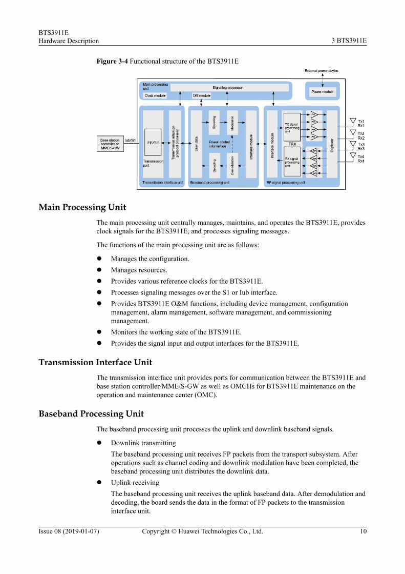
Figure 3-4 Functional structure of the BTS3911E
Main Processing UnitThe main processing unit centrally manages, maintains, and operates the BTS3911E, providesclock signals for the BTS3911E, and processes signaling messages.
The functions of the main processing unit are as follows:
l Manages the configuration.l Manages resources.l Provides various reference clocks for the BTS3911E.l Processes signaling messages over the S1 or Iub interface.l Provides BTS3911E O&M functions, including device management, configuration
management, alarm management, software management, and commissioningmanagement.
l Monitors the working state of the BTS3911E.l Provides the signal input and output interfaces for the BTS3911E.
Transmission Interface UnitThe transmission interface unit provides ports for communication between the BTS3911E andbase station controller/MME/S-GW as well as OMCHs for BTS3911E maintenance on theoperation and maintenance center (OMC).
Baseband Processing UnitThe baseband processing unit processes the uplink and downlink baseband signals.
l Downlink transmittingThe baseband processing unit receives FP packets from the transport subsystem. Afteroperations such as channel coding and downlink modulation have been completed, thebaseband processing unit distributes the downlink data.
l Uplink receivingThe baseband processing unit receives the uplink baseband data. After demodulation anddecoding, the board sends the data in the format of FP packets to the transmissioninterface unit.
BTS3911EHardware Description 3 BTS3911E
Issue 08 (2019-01-07) Copyright © Huawei Technologies Co., Ltd. 10

l Closed-loop processing for the physical layerThe baseband signal processing unit implements the closed-loop processing foracquisition indication (AI), the closed-loop power control of the uplink and downlink atthe physical layer, and the closed-loop transmit diversity of the downlink.
RF Processing UnitThe RF processing unit modulates, demodulates, processes, combines, and divides RF signals.
l The functions of the downlink TX channel are as follows:– Shaping and filtering of downlink spread spectrum signals– Digital-to-analog conversion– Up-conversion of IF signals to the transmitting band
l The functions of uplink RX channels are as follows:– Down-conversion of received signals to IF signals– Amplification of the IF signals– Analog-to-digital conversion– Digital down-conversion– Matched filtering– Digital automatic gain control (DAGC)
Power ModuleThe power module obtains power from external power devices and supplies power to otherunits of the BTS3911E.
BTS3911EHardware Description 3 BTS3911E
Issue 08 (2019-01-07) Copyright © Huawei Technologies Co., Ltd. 11

4 BTS3911E Cables
This section describes the BTS3911E cables in terms of the appearance, core wire type, andinstallation position.
4.1 Cable ListThis section describes the connection positions and connector types of BTS3911E cables.
4.2 PGND CableA PGND cable connects the ground terminal of a BTS3911E to a ground bar, providingground protection for the BTS3911E.
4.3 Power CableThe power cable connects the BTS3911E to external power supply equipment that can supplyAC power to the BTS3911E.
4.4 FE/GE Ethernet CableAn FE/GE Ethernet cable transmits FE/GE signals between a BTS3911E and the externaltransmission equipment or between two BTS3911Es.
4.5 FE/GE Optical CableAn FE/GE optical cable transmits optical signals between a BTS3911E and transmissionequipment or between two BTS3911Es.
4.6 Alarm CableAn alarm cable transmits alarm signals from external equipment to a BTS3911E so that theBTS3911E can monitor the operating status of the external equipment.
4.7 (Optional) RF JumperThe 1/2" RF jumper is used for the BTS3911E to transmit and receive RF signals.
4.1 Cable ListThis section describes the connection positions and connector types of BTS3911E cables.
BTS3911E cables include the PGND cable, power cable, FE/GE Ethernet cable, FE/GEoptical cable, CPRI optical cable, alarm cable, and RF jumper. Table 4-1 lists the BTS3911Ecables.
BTS3911EHardware Description 4 BTS3911E Cables
Issue 08 (2019-01-07) Copyright © Huawei Technologies Co., Ltd. 12
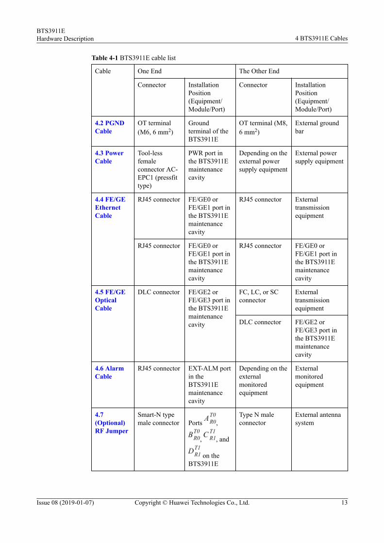
Table 4-1 BTS3911E cable list
Cable One End The Other End
Connector InstallationPosition(Equipment/Module/Port)
Connector InstallationPosition(Equipment/Module/Port)
4.2 PGNDCable
OT terminal(M6, 6 mm2)
Groundterminal of theBTS3911E
OT terminal (M8,6 mm2)
External groundbar
4.3 PowerCable
Tool-lessfemaleconnector AC-EPC1 (pressfittype)
PWR port inthe BTS3911Emaintenancecavity
Depending on theexternal powersupply equipment
External powersupply equipment
4.4 FE/GEEthernetCable
RJ45 connector FE/GE0 orFE/GE1 port inthe BTS3911Emaintenancecavity
RJ45 connector Externaltransmissionequipment
RJ45 connector FE/GE0 orFE/GE1 port inthe BTS3911Emaintenancecavity
RJ45 connector FE/GE0 orFE/GE1 port inthe BTS3911Emaintenancecavity
4.5 FE/GEOpticalCable
DLC connector FE/GE2 orFE/GE3 port inthe BTS3911Emaintenancecavity
FC, LC, or SCconnector
Externaltransmissionequipment
DLC connector FE/GE2 orFE/GE3 port inthe BTS3911Emaintenancecavity
4.6 AlarmCable
RJ45 connector EXT-ALM portin theBTS3911Emaintenancecavity
Depending on theexternalmonitoredequipment
Externalmonitoredequipment
4.7(Optional)RF Jumper
Smart-N typemale connector Ports ,
, , and
on theBTS3911E
Type N maleconnector
External antennasystem
BTS3911EHardware Description 4 BTS3911E Cables
Issue 08 (2019-01-07) Copyright © Huawei Technologies Co., Ltd. 13
4.2 PGND CableA PGND cable connects the ground terminal of a BTS3911E to a ground bar, providingground protection for the BTS3911E.
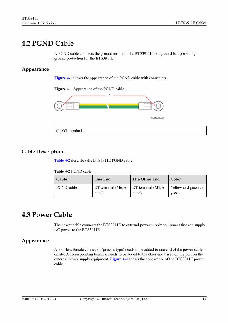
AppearanceFigure 4-1 shows the appearance of the PGND cable with connectors.
Figure 4-1 Appearance of the PGND cable
(1) OT terminal
Cable DescriptionTable 4-2 describes the BTS3911E PGND cable.
Table 4-2 PGND cable
Cable One End The Other End Color
PGND cable OT terminal (M6, 6mm2)
OT terminal (M8, 6mm2)
Yellow and green orgreen
4.3 Power CableThe power cable connects the BTS3911E to external power supply equipment that can supplyAC power to the BTS3911E.
AppearanceA tool-less female connector (pressfit type) needs to be added to one end of the power cableonsite. A corresponding terminal needs to be added to the other end based on the port on theexternal power supply equipment. Figure 4-2 shows the appearance of the BTS3911E powercable.
BTS3911EHardware Description 4 BTS3911E Cables
Issue 08 (2019-01-07) Copyright © Huawei Technologies Co., Ltd. 14
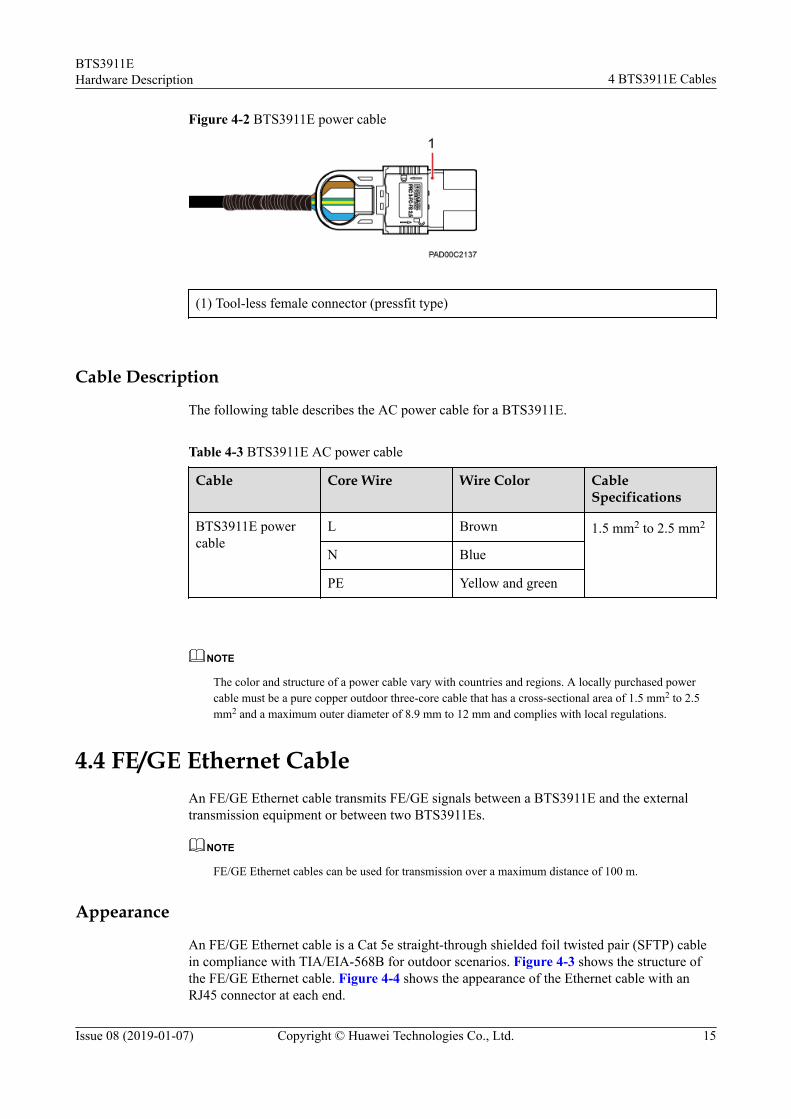
Figure 4-2 BTS3911E power cable
(1) Tool-less female connector (pressfit type)
Cable Description
The following table describes the AC power cable for a BTS3911E.
Table 4-3 BTS3911E AC power cable
Cable Core Wire Wire Color CableSpecifications
BTS3911E powercable
L Brown 1.5 mm2 to 2.5 mm2
N Blue
PE Yellow and green
NOTE
The color and structure of a power cable vary with countries and regions. A locally purchased powercable must be a pure copper outdoor three-core cable that has a cross-sectional area of 1.5 mm2 to 2.5mm2 and a maximum outer diameter of 8.9 mm to 12 mm and complies with local regulations.
4.4 FE/GE Ethernet CableAn FE/GE Ethernet cable transmits FE/GE signals between a BTS3911E and the externaltransmission equipment or between two BTS3911Es.
NOTE
FE/GE Ethernet cables can be used for transmission over a maximum distance of 100 m.
Appearance
An FE/GE Ethernet cable is a Cat 5e straight-through shielded foil twisted pair (SFTP) cablein compliance with TIA/EIA-568B for outdoor scenarios. Figure 4-3 shows the structure ofthe FE/GE Ethernet cable. Figure 4-4 shows the appearance of the Ethernet cable with anRJ45 connector at each end.
BTS3911EHardware Description 4 BTS3911E Cables
Issue 08 (2019-01-07) Copyright © Huawei Technologies Co., Ltd. 15
NOTE
Ethernet cables of a higher level can also be used. For detailed specifications, see standards related toEthernet cables.
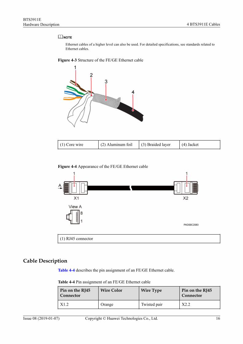
Figure 4-3 Structure of the FE/GE Ethernet cable
(1) Core wire (2) Aluminum foil (3) Braided layer (4) Jacket
Figure 4-4 Appearance of the FE/GE Ethernet cable
(1) RJ45 connector
Cable Description
Table 4-4 describes the pin assignment of an FE/GE Ethernet cable.
Table 4-4 Pin assignment of an FE/GE Ethernet cable
Pin on the RJ45Connector
Wire Color Wire Type Pin on the RJ45Connector
X1.2 Orange Twisted pair X2.2
BTS3911EHardware Description 4 BTS3911E Cables
Issue 08 (2019-01-07) Copyright © Huawei Technologies Co., Ltd. 16
Pin on the RJ45Connector
Wire Color Wire Type Pin on the RJ45Connector
X1.1 White/orange X2.1
X1.6 Green Twisted pair X2.6
X1.3 White/green X2.3
X1.4 Blue Twisted pair X2.4
X1.5 White/blue X2.5
X1.8 Brown Twisted pair X2.8
X1.7 White/brown X2.7
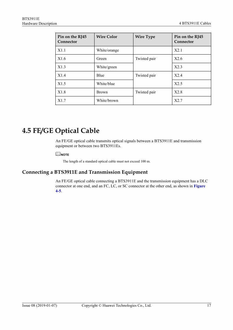
4.5 FE/GE Optical CableAn FE/GE optical cable transmits optical signals between a BTS3911E and transmissionequipment or between two BTS3911Es.
NOTE
The length of a standard optical cable must not exceed 100 m.
Connecting a BTS3911E and Transmission EquipmentAn FE/GE optical cable connecting a BTS3911E and the transmission equipment has a DLCconnector at one end, and an FC, LC, or SC connector at the other end, as shown in Figure4-5.
BTS3911EHardware Description 4 BTS3911E Cables
Issue 08 (2019-01-07) Copyright © Huawei Technologies Co., Ltd. 17
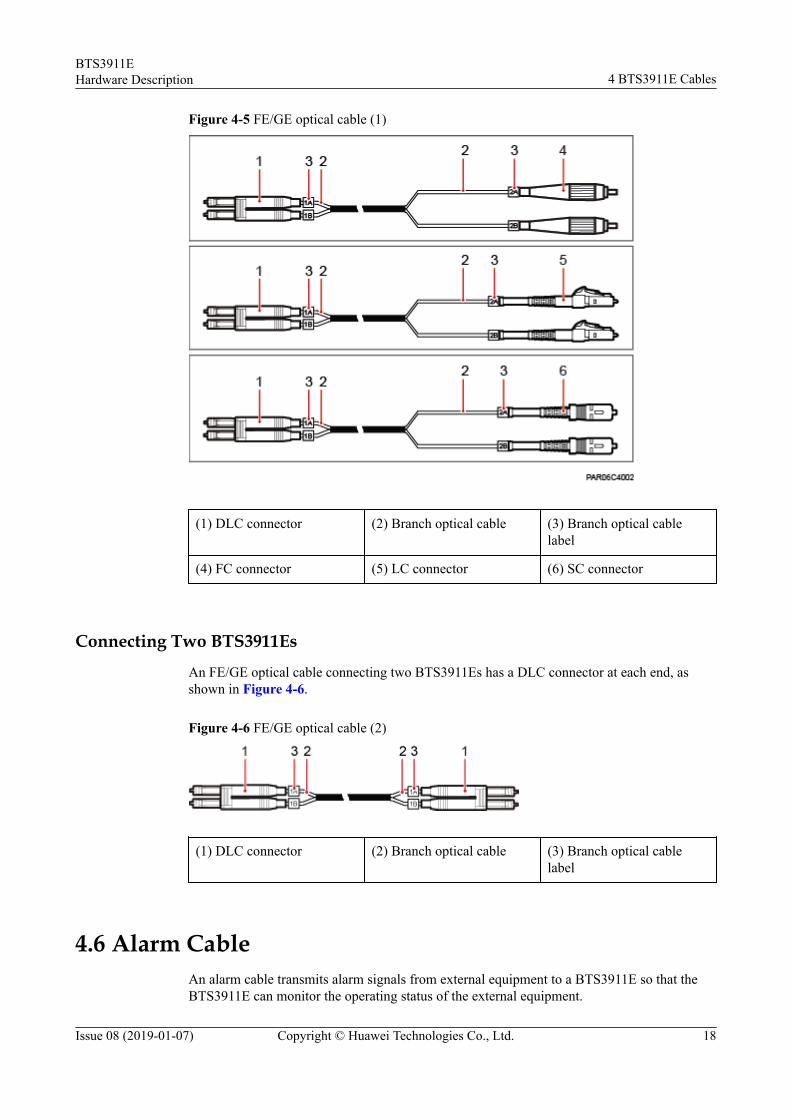
Figure 4-5 FE/GE optical cable (1)
(1) DLC connector (2) Branch optical cable (3) Branch optical cablelabel
(4) FC connector (5) LC connector (6) SC connector
Connecting Two BTS3911Es
An FE/GE optical cable connecting two BTS3911Es has a DLC connector at each end, asshown in Figure 4-6.
Figure 4-6 FE/GE optical cable (2)
(1) DLC connector (2) Branch optical cable (3) Branch optical cablelabel
4.6 Alarm CableAn alarm cable transmits alarm signals from external equipment to a BTS3911E so that theBTS3911E can monitor the operating status of the external equipment.
BTS3911EHardware Description 4 BTS3911E Cables
Issue 08 (2019-01-07) Copyright © Huawei Technologies Co., Ltd. 18

Appearance
An RJ45 connector needs to be added to one end of a BTS3911E alarm cable. Acorresponding terminal needs to be added to the other end based on the port on the externalmonitored equipment. Figure 4-7 shows the appearance of the alarm cable.
Figure 4-7 Appearance of the alarm cable
(1) RJ45 connector
Cable Description
Table 4-5 describes the pin assignment of the alarm cable.
Table 4-5 Pin assignment of the alarm cable
Pin Wire Color Wire Type Description
X1.1 White/orange Twisted pair Boolean input 0+
X1.2 Orange Boolean input 0–(GND)
X1.3 White/green Twisted pair Boolean input 1+
X1.6 Green Boolean input 1–(GND)
X1.5 White/blue Twisted pair Boolean input 2+
X1.4 Blue Boolean input 2–(GND)
X1.7 White/brown Twisted pair Boolean input 3+
X1.8 Brown Boolean input 3–(GND)
4.7 (Optional) RF JumperThe 1/2" RF jumper is used for the BTS3911E to transmit and receive RF signals.
BTS3911EHardware Description 4 BTS3911E Cables
Issue 08 (2019-01-07) Copyright © Huawei Technologies Co., Ltd. 19
An RF jumper has a type N male connector at one end and a Smart-N-type male connector atthe other end. Figure 4-8 shows the appearance of the RF jumper.
Figure 4-8 Appearance of the RF jumper
(1) Smart-N-type male connector (2) Type N male connector
BTS3911EHardware Description 4 BTS3911E Cables
Issue 08 (2019-01-07) Copyright © Huawei Technologies Co., Ltd. 20

5 Auxiliary Devices
This section describes auxiliary devices of the BTS3911E, including the GPS antenna, DIN-male N-female connector, and optical module.
5.1 (Optional) GPS AntennaA GPS antenna connects to the BTS3911E for clock synchronization. The GPS antenna isoptional.
5.2 (Optional) DIN-Male N-Female Connector
5.3 Optical ModuleAn optical module transmits optical signals between an optical port and an optical cable.
5.1 (Optional) GPS AntennaA GPS antenna connects to the BTS3911E for clock synchronization. The GPS antenna isoptional.
AppearanceA GPS antenna has a Smart-N-type male connector at one end. Figure 5-1 shows theappearance of the GPS antenna.
BTS3911EHardware Description 5 Auxiliary Devices
Issue 08 (2019-01-07) Copyright © Huawei Technologies Co., Ltd. 21

Figure 5-1 Appearance of the GPS antenna
(1) GPS antenna (2) Smart-N-type male connector
Specifications
Item Specifications
Frequency (MHz) 1574.42 to 1576.42
Antenna type Omnidirectional
Polarization mode Right-hand circular polarization
Antenna gain (dBi) 4
Horizontal beamwidth (°) 360
Vertical beamwidth (°) 110
VSWR ≤ 2
LNA gain (dB) 35
Noise factor l < 2.5 (25°C)l < 3 (85°C)
Dimensions (mm) Φ50 x 14
Weight (Kg) < 1.0
BTS3911EHardware Description 5 Auxiliary Devices
Issue 08 (2019-01-07) Copyright © Huawei Technologies Co., Ltd. 22
Item Specifications
Operating temperature l Without sunlight exposure: –40°C to +55°Cl With sunlight exposure: –40°C to +50°C
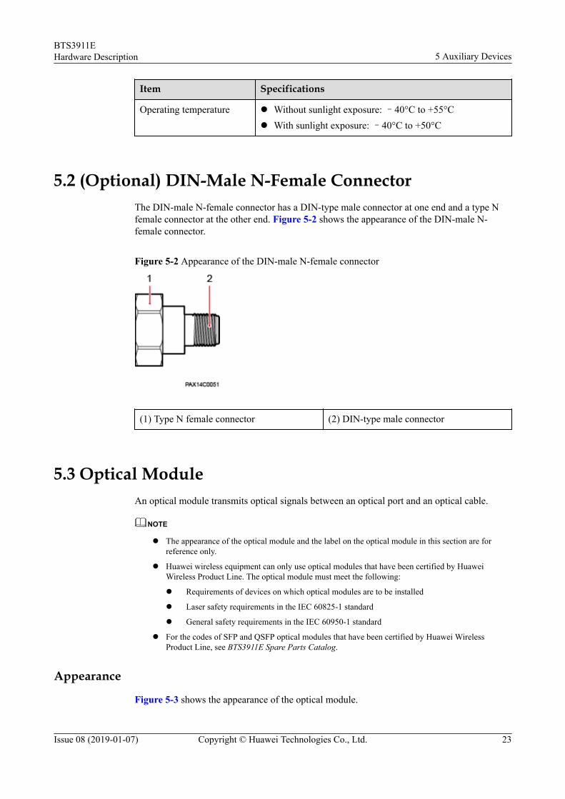
5.2 (Optional) DIN-Male N-Female ConnectorThe DIN-male N-female connector has a DIN-type male connector at one end and a type Nfemale connector at the other end. Figure 5-2 shows the appearance of the DIN-male N-female connector.
Figure 5-2 Appearance of the DIN-male N-female connector
(1) Type N female connector (2) DIN-type male connector
5.3 Optical ModuleAn optical module transmits optical signals between an optical port and an optical cable.
NOTE
l The appearance of the optical module and the label on the optical module in this section are forreference only.
l Huawei wireless equipment can only use optical modules that have been certified by HuaweiWireless Product Line. The optical module must meet the following:
l Requirements of devices on which optical modules are to be installed
l Laser safety requirements in the IEC 60825-1 standard
l General safety requirements in the IEC 60950-1 standard
l For the codes of SFP and QSFP optical modules that have been certified by Huawei WirelessProduct Line, see BTS3911E Spare Parts Catalog.
Appearance
Figure 5-3 shows the appearance of the optical module.
BTS3911EHardware Description 5 Auxiliary Devices
Issue 08 (2019-01-07) Copyright © Huawei Technologies Co., Ltd. 23

Figure 5-3 Appearance of the optical module
Label on the Optical ModuleThere is a label on each optical module, which provides information such as the rate,wavelength, and transmission mode. See Figure 5-4.
Figure 5-4 Label on the optical module
(1) Rate (2) Wavelength (3) Transmission mode
NOTE
The rate, say 2.125 Gbit/s, in the preceding figure is for reference only. Optical modules used indifferent base stations have different rates.
BTS3911EHardware Description 5 Auxiliary Devices
Issue 08 (2019-01-07) Copyright © Huawei Technologies Co., Ltd. 24

6 Typical Networking and Cable Connection
This section describes the BTS3911E networking modes and cable connection principles.
6.1 Cable Connection PrinciplesThis section describes the connection principles for the PGND cable, power cable,transmission cable, alarm cable, and RF jumper.
6.1 Cable Connection PrinciplesThis section describes the connection principles for the PGND cable, power cable,transmission cable, alarm cable, and RF jumper.
PGND CableThe PGND cable length must not exceed 30 m.
Power CableThe power cable length must not exceed 100 m.
Transmission Cablel An Ethernet cable or optical cable can be used for signal transmission between a
BTS3911E and the MME/S-GW/RNC. The length of a standard optical cable must notexceed 100 m. An Ethernet cable must be made onsite, with a maximum length of 100m.
l A maximum of three BTS3911Es can be cascaded over Ethernet cables or optical cables(recommended). The maximum distance between two BTS3911Es cascaded over anEthernet cable is 100 m.
Alarm CableThe alarm cable length must not exceed 100 m.
BTS3911EHardware Description 6 Typical Networking and Cable Connection
Issue 08 (2019-01-07) Copyright © Huawei Technologies Co., Ltd. 25
RF JumperThe RF jumper length depends on scenario-specific coverage requirements and must notexceed 10 m.
BTS3911EHardware Description 6 Typical Networking and Cable Connection
Issue 08 (2019-01-07) Copyright © Huawei Technologies Co., Ltd. 26
7 Power Requirements
This section describes the requirements on the upper-level (customer-provided) circuitbreakers and cross-sectional areas.
Type C bipolar circuit breakers in accordance with IEC 60934 are recommended. Circuitbreakers must be configured for L and N wires for the sake of O&M security.
Slow-blow fuses of the gL (DIN VDE)/gG (IEC) class in accordance with IEC 60269-1 arerecommended. Fuses of the same specifications must be configured for L and N wires for thesake of O&M security.
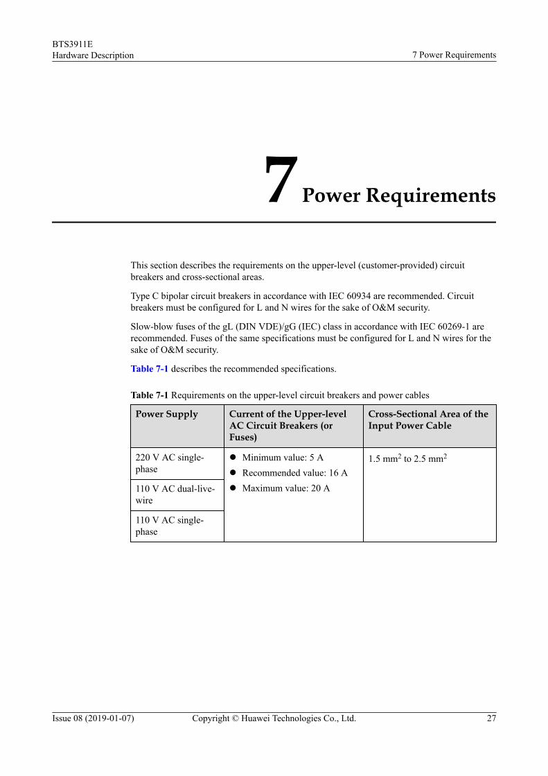
Table 7-1 describes the recommended specifications.
Table 7-1 Requirements on the upper-level circuit breakers and power cables
Power Supply Current of the Upper-levelAC Circuit Breakers (orFuses)
Cross-Sectional Area of theInput Power Cable
220 V AC single-phase
l Minimum value: 5 Al Recommended value: 16 Al Maximum value: 20 A
1.5 mm2 to 2.5 mm2
110 V AC dual-live-wire
110 V AC single-phase
BTS3911EHardware Description 7 Power Requirements
Issue 08 (2019-01-07) Copyright © Huawei Technologies Co., Ltd. 27
NOTE
l The requirements provided in the preceding table are based on the peak power of base station and donot represent power consumption when the base station is running.
l Minimum value: Ensures that a base station can work normally under normal circumstances.However, lightning strikes or abnormal voltage fluctuations may trip the circuit breaker or melt thefuse.
l Recommended value: Ensures that a base station can work normally under normal circumstancesand that the circuit breaker does not trip in the event of lightning strikes or abnormal voltagefluctuations.
l Maximum value: Indicates the maximum rated current allowed for the circuit breaker or fuse whenthe base station is working properly.
BTS3911EHardware Description 7 Power Requirements
Issue 08 (2019-01-07) Copyright © Huawei Technologies Co., Ltd. 28
8 Engineering Specifications
This section describes the BTS3911E engineering specifications, including power supplyspecifications, equipment specifications, environment specifications, surge protectionspecifications for the ports on the BTS3911E, and standards that the BTS3911E complieswith.
For more details, see Micro BTS3900 Series Technical Description.
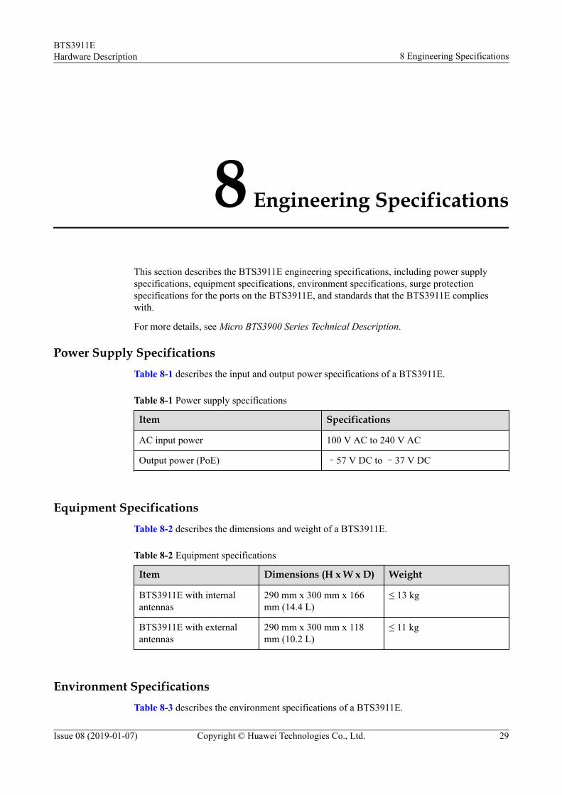
Power Supply SpecificationsTable 8-1 describes the input and output power specifications of a BTS3911E.
Table 8-1 Power supply specifications
Item Specifications
AC input power 100 V AC to 240 V AC
Output power (PoE) –57 V DC to –37 V DC
Equipment SpecificationsTable 8-2 describes the dimensions and weight of a BTS3911E.
Table 8-2 Equipment specifications
Item Dimensions (H x W x D) Weight
BTS3911E with internalantennas
290 mm x 300 mm x 166mm (14.4 L)
≤ 13 kg
BTS3911E with externalantennas
290 mm x 300 mm x 118mm (10.2 L)
≤ 11 kg
Environment SpecificationsTable 8-3 describes the environment specifications of a BTS3911E.
BTS3911EHardware Description 8 Engineering Specifications
Issue 08 (2019-01-07) Copyright © Huawei Technologies Co., Ltd. 29
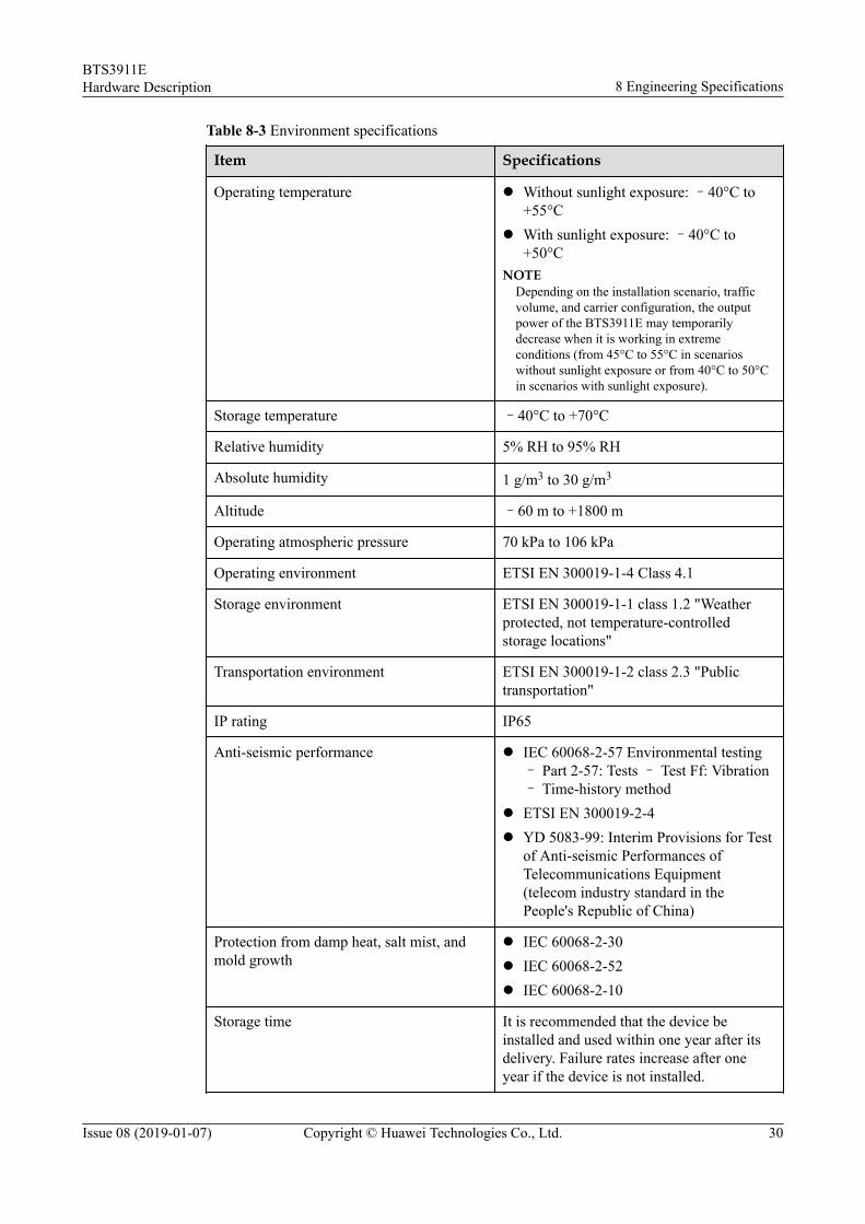
Table 8-3 Environment specifications
Item Specifications
Operating temperature l Without sunlight exposure: –40°C to+55°C
l With sunlight exposure: –40°C to+50°C
NOTEDepending on the installation scenario, trafficvolume, and carrier configuration, the outputpower of the BTS3911E may temporarilydecrease when it is working in extremeconditions (from 45°C to 55°C in scenarioswithout sunlight exposure or from 40°C to 50°Cin scenarios with sunlight exposure).
Storage temperature –40°C to +70°C
Relative humidity 5% RH to 95% RH
Absolute humidity 1 g/m3 to 30 g/m3
Altitude –60 m to +1800 m
Operating atmospheric pressure 70 kPa to 106 kPa
Operating environment ETSI EN 300019-1-4 Class 4.1
Storage environment ETSI EN 300019-1-1 class 1.2 "Weatherprotected, not temperature-controlledstorage locations"
Transportation environment ETSI EN 300019-1-2 class 2.3 "Publictransportation"
IP rating IP65
Anti-seismic performance l IEC 60068-2-57 Environmental testing– Part 2-57: Tests – Test Ff: Vibration– Time-history method
l ETSI EN 300019-2-4l YD 5083-99: Interim Provisions for Test
of Anti-seismic Performances ofTelecommunications Equipment(telecom industry standard in thePeople's Republic of China)
Protection from damp heat, salt mist, andmold growth
l IEC 60068-2-30l IEC 60068-2-52l IEC 60068-2-10
Storage time It is recommended that the device beinstalled and used within one year after itsdelivery. Failure rates increase after oneyear if the device is not installed.
BTS3911EHardware Description 8 Engineering Specifications
Issue 08 (2019-01-07) Copyright © Huawei Technologies Co., Ltd. 30
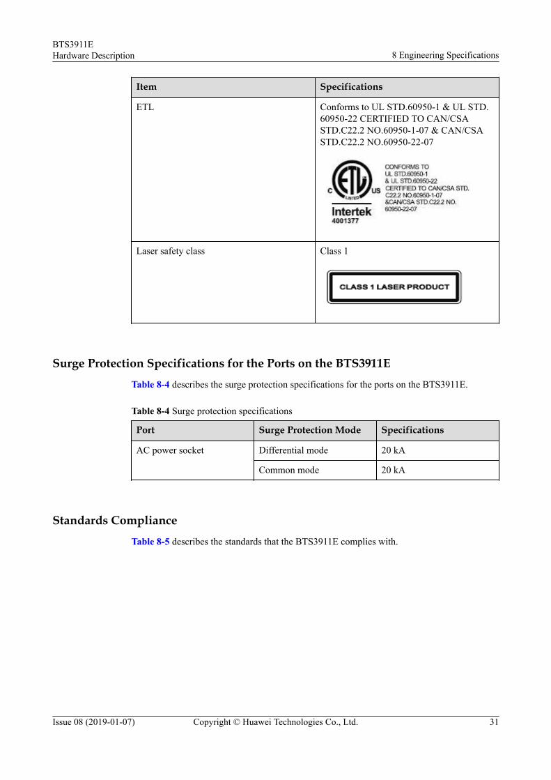
Item Specifications
ETL Conforms to UL STD.60950-1 & UL STD.60950-22 CERTIFIED TO CAN/CSASTD.C22.2 NO.60950-1-07 & CAN/CSASTD.C22.2 NO.60950-22-07
Laser safety class Class 1
Surge Protection Specifications for the Ports on the BTS3911ETable 8-4 describes the surge protection specifications for the ports on the BTS3911E.
Table 8-4 Surge protection specifications
Port Surge Protection Mode Specifications
AC power socket Differential mode 20 kA
Common mode 20 kA
Standards ComplianceTable 8-5 describes the standards that the BTS3911E complies with.
BTS3911EHardware Description 8 Engineering Specifications
Issue 08 (2019-01-07) Copyright © Huawei Technologies Co., Ltd. 31
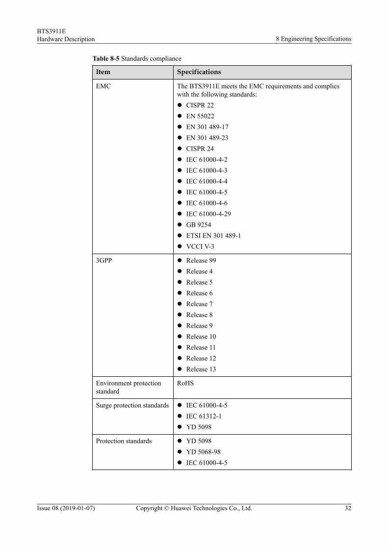
Table 8-5 Standards compliance
Item Specifications
EMC The BTS3911E meets the EMC requirements and complieswith the following standards:l CISPR 22l EN 55022l EN 301 489-17l EN 301 489-23l CISPR 24l IEC 61000-4-2l IEC 61000-4-3l IEC 61000-4-4l IEC 61000-4-5l IEC 61000-4-6l IEC 61000-4-29l GB 9254l ETSI EN 301 489-1l VCCI V-3
3GPP l Release 99l Release 4l Release 5l Release 6l Release 7l Release 8l Release 9l Release 10l Release 11l Release 12l Release 13
Environment protectionstandard
RoHS
Surge protection standards l IEC 61000-4-5l IEC 61312-1l YD 5098
Protection standards l YD 5098l YD 5068-98l IEC 61000-4-5
BTS3911EHardware Description 8 Engineering Specifications
Issue 08 (2019-01-07) Copyright © Huawei Technologies Co., Ltd. 32

Item Specifications
Safety standards l UL 60950-1l IEC 60950-1l EN 60950-1l AS/NZS 60950-1l UL 60950-22l IEC 60950-22l EN 60950-22l AS/NZS 60950-22
Environment standards l IEC 68-2-1l IEC 68-2-2l IEC 60068-2-2l ETSI EN 300 019-1-1l ETSI EN 300 019-1-2l ETSI EN 300 019-1-4l ETSI EN 300 019-2-4
BTS3911EHardware Description 8 Engineering Specifications
Issue 08 (2019-01-07) Copyright © Huawei Technologies Co., Ltd. 33


