Hardware for ECU Testing During functional tests a modern and flexible test system must control the I/O interfaces of the ECU. Test cases make different demands on the connection and the operation of sensors and actuators, as well as the signalling or errors and measurement of signals. Beside the different challenges to the test system this article describes a new test hardware by Vector Informatik. TESTING Hardware 52 ATZelektronik 01I2008 Volume 3
Transcript
Hardware for ECU TestingDuring functional tests a modern and flexible test system must control the I/O interfaces of the ECU. Test cases make different demands on the connection and the operation of sensors and actuators, as well as the signalling or errors and measurement of signals. Beside the different challenges to the test system this article describes a new test hardware by Vector Informatik.
TesTing Hardware
52 ATZelektronik 01i2008 Volume 3
1 Introduction
Electronics and software have become indispensable components in the auto-mobile. Verification of development re-sults therefore not only covers the me-chanical systems, but to a great extent also the electronic control units (ECUs) and their software. The complexity of the highly networked systems places high demands on the testing process. Therefore, systematic and comprehen-sive tests are necessary in all phases of development.
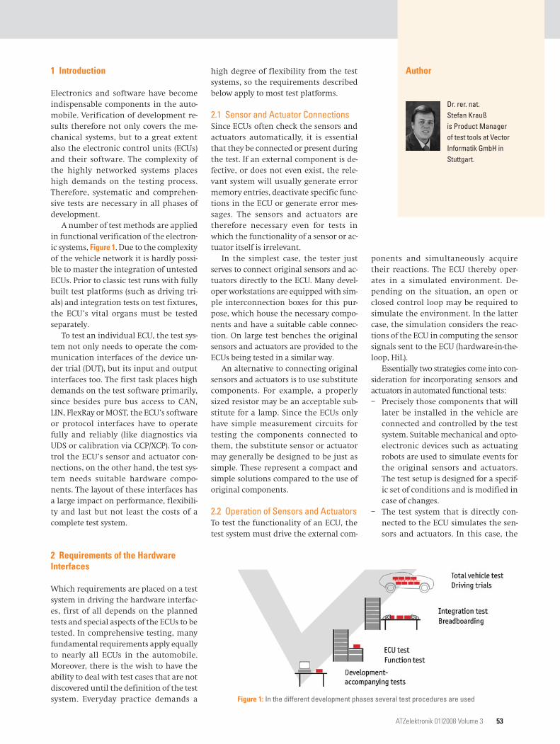
A number of test methods are applied in functional verification of the electron-ic systems, Figure 1. Due to the complexity of the vehicle network it is hardly possi-ble to master the integration of untested ECUs. Prior to classic test runs with fully built test platforms (such as driving tri-als) and integration tests on test fixtures, the ECU’s vital organs must be tested separately.
To test an individual ECU, the test sys-tem not only needs to operate the com-munication interfaces of the device un-der trial (DUT), but its input and output interfaces too. The first task places high demands on the test software primarily, since besides pure bus access to CAN, LIN, FlexRay or MOST, the ECU’s software or protocol interfaces have to operate fully and reliably (like diagnostics via UDS or calibration via CCP/XCP). To con-trol the ECU’s sensor and actuator con-nections, on the other hand, the test sys-tem needs suitable hardware compo-nents. The layout of these interfaces has a large impact on performance, flexibili-ty and last but not least the costs of a complete test system.
2 Requirements of the Hardware Interfaces
Which requirements are placed on a test system in driving the hardware interfac-es, first of all depends on the planned tests and special aspects of the ECUs to be tested. In comprehensive testing, many fundamental requirements apply equally to nearly all ECUs in the automobile. Moreover, there is the wish to have the ability to deal with test cases that are not discovered until the definition of the test system. Everyday practice demands a
high degree of flexibility from the test systems, so the requirements described below apply to most test platforms.
2.1 Sensor and Actuator ConnectionsSince ECUs often check the sensors and actuators automatically, it is essential that they be connected or present during the test. If an external component is de-fective, or does not even exist, the rele-vant system will usually generate error memory entries, deactivate specific func-tions in the ECU or generate error mes-sages. The sensors and actuators are therefore necessary even for tests in which the functionality of a sensor or ac-tuator itself is irrelevant.
In the simplest case, the tester just serves to connect original sensors and ac-tuators directly to the ECU. Many devel-oper workstations are equipped with sim-ple interconnection boxes for this pur-pose, which house the necessary compo-nents and have a suitable cable connec-tion. On large test benches the original sensors and actuators are provided to the ECUs being tested in a similar way.
An alternative to connecting original sensors and actuators is to use substitute components. For example, a properly sized resistor may be an acceptable sub-stitute for a lamp. Since the ECUs only have simple measurement circuits for testing the components connected to them, the substitute sensor or actuator may generally be designed to be just as simple. These represent a compact and simple solutions compared to the use of original components.
2.2 Operation of Sensors and ActuatorsTo test the functionality of an ECU, the test system must drive the external com-
ponents and simultaneously acquire their reactions. The ECU thereby oper-ates in a simulated environment. De-pending on the situation, an open or closed control loop may be required to simulate the environment. In the latter case, the simulation considers the reac-tions of the ECU in computing the sensor signals sent to the ECU (hardware-in-the-loop, HiL).
Essentially two strategies come into con-sideration for incorporating sensors and actuators in automated functional tests:– Precisely those components that will
later be installed in the vehicle are connected and controlled by the test system. Suitable mechanical and opto-electronic devices such as actuating robots are used to simulate events for the original sensors and actuators. The test setup is designed for a specif-ic set of conditions and is modified in case of changes.
– The test system that is directly con-nected to the ECU simulates the sen-sors and actuators. In this case, the
Author
Dr. rer. nat. Stefan Krauß is Product Manager of test tools at Vector Informatik GmbH in Stuttgart.
Figure 1: In the different development phases several test procedures are used
ATZelektronik 01i2008 Volume 3 53
test system is capable of electrically emulating sensor outputs and loads. While it measures the activities of the ECU at the ECU outputs, it places sig-nals representing relevant sensor po-sitions at the inputs.
When original components are used, the tester does not need to be concerned about how realistic the simulation is, but the simulation is limited to the prop-erties of the components used. This lim-its the flexibility of the test bench. Sys-tematic testing of ECU behavior in re-sponse to slight differences in sensors and actuators (component variance) is not possible, for example. In contrast, universal simulation capability offers the additional advantage, that the test bench may be used for different ECUs without requiring major modifications.
In conjunction with tests, when sen-sors and actuators are simulated, this usually does not imply that there is a simulation model in the test system that represents their physical properties pre-cisely. It is sufficient, for example, if the test system provides the voltage expected from a sensor or simulates the load of an actuator by suitable current flow. From the perspective of the ECU, the test sys-tem nonetheless simulates the sensors and actuators, although perhaps not in every detail.
2.3 Signalling of ErrorsTo test the reactions of an ECU to errors in the connected environment, the test system must represent relevant errors. Potential error conditions include:– Problems with the connection lines of
sensors and actuators: line breaks, short circuits between wire pairs, short circuits of individual lines to ground or battery voltage.
– Defects of the sensors and actuators themselves, such as excessively high or low internal resistance of an actua-tor or excessively high current con-sumption of an active sensor.
– Sensor signals outside of the specified value range, like physically impossible values of a rotary encoder or implau-sibly high temperature values of a temperature sensor.
Detailed tests under these error condi-tions are especially important, because they occur very sporadically during vehi-cle trials and on test fixtures, and they
therefore exhibit poor reproducibility. Such causes of errors are frequently ne-glected in the development of hardware and software too, because the develop-er’s primary focus is on the desired func-tions. To achieve system reliability, how-ever, it is crucial that the ECUs also react properly in error situations.
2.4 MeasurementIn the test cases, reference values are specified for certain relevant control variables, which are compared to actual values at the ECU outputs. The test sys-tem must therefore be capable of meas-uring the relevant variables at a resolu-tion and precision appropriate to the test case. Coming into consideration as meas-urement variables are momentary values as well as mean values and effective val-ues. Increasingly, characteristic parame-ters such as frequencies and duty cycles of pulse-width modulated signals are in demand, since many actuators are now driven with PWM signals, such as bright-ness control of the LEDs in the instru-ment cluster.
3 Integrated Solution for I/O Control
Vector Informatik supports analysis, sim-ulation and automated testing of ECUs with the powerful development and test tool CANoe [1]. Vector hardware interfac-es also provide for a reliable bus access to CAN, LIN, FlexRay or MOST. Test benches of a wide range of complexity can be set up using drive control of measurement and test hardware via GPIB or the serial port and integration of standard I/O cards from various producers.
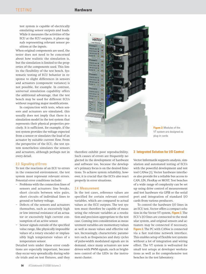
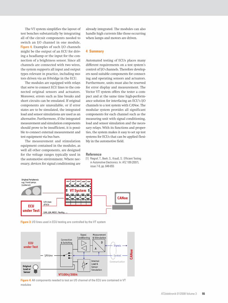
To control the hardware I/O lines in an ECU test, Vector offers a compact solu-tion in the Vector VT system, Figure 2. The ECU’s I/O lines are connected to the mod-ular system, and original sensors and ac-tuators may be connected if necessary, Figure 3. The PC with CANoe is connected via a fast real-time network interface. This enables setup of flexible test systems without a lot of integration and wiring effort. The VT system is well-suited for small test setups at developer worksta-tions as well as for comprehensive test benches in the test laboratory.
Figure 2: Modules of the VT system are designed as plug-in cards
TesTing Hardware
54 ATZelektronik 01i2008 Volume 3
The VT system simplifies the layout of test benches substantially by integrating all of the circuit components needed to switch an I/O channel in one module, Figure 4. Examples of such I/O channels might be the output of an ECU for driv-ing a headlamp or the input for the con-nection of a brightness sensor. Since all channels are connected with two wires, the system supports all input and output types relevant in practice, including mo-tors driven via an H-bridge in the ECU.
The modules are equipped with relays that serve to connect ECU lines to the con-nected original sensors and actuators. Moreover, errors such as line breaks and short circuits can be emulated. If original components are unavailable, or if error states are to be simulated, the integrated load and sensor simulations are used as an alternative. Furthermore, if the integrated measurement and simulation components should prove to be insufficient, it is possi-ble to connect external measurement and test equipment via bus bars.
The measurement and stimulation equipment contained in the modules, as well all other components, are designed for the voltage ranges typically used in the automotive environment. Where nec-essary, devices for signal conditioning are
already integrated. The modules can also handle high currents like those occurring when lamps and motors are driven.
4 Summary
Automated testing of ECUs places many different requirements on a test system’s control of I/O channels. Therefore develop-ers need suitable components for connect-ing and operating sensors and actuators. Furthermore, units must also be reserved for error display and measurement. The Vector VT system offers the tester a com-pact and at the same time high-perform-ance solution for interfacing an ECU’s I/O channels to a test system with CANoe. The modular system provides all significant components for each channel such as the measuring unit with signal conditioning, load and sensor simulation and the neces-sary relays. With its functions and proper-ties, the system makes it easy to set up test systems for ECUs that can be applied flexi-bly in the automotive field.