HARDWARE-IN-THE-LOOP TEST RIG FOR NEAR-EARTH AERIAL ROBOTICS Vefa Narli, Paul Y. Oh Drexel Autonomous Systems Lab (DASL) Mechanical Engineering and Mechanics, Drexel University 2006 ASME International Design Engineering Technical Conferences
Transcript
HARDWARE-IN-THE-LOOPTEST RIG FOR
NEAR-EARTH AERIAL ROBOTICS
Vefa Narli, Paul Y. OhDrexel Autonomous Systems Lab (DASL)
Mechanical Engineering and Mechanics, Drexel University
2006 ASME International Design Engineering Technical Conferences
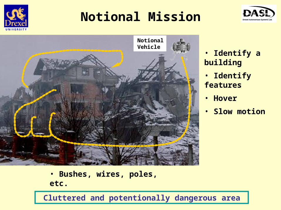
Mission Environments
Robots to handle dirty, dangerous and dull missions
Current approach:Ad-hoc with manycrashes andband-aid fixes
Gap: No Sensor metrics to design analytically
“A MAV that flies like an airplane and hovers like a helicopter”, William E. Green, Paul Y. Oh, IEEE/ASME July 2005
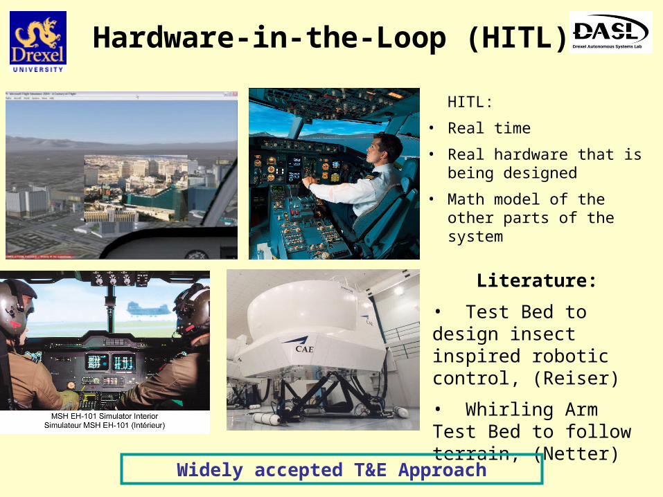
Hardware-in-the-Loop (HITL)
HITL:
• Real time
• Real hardware that is being designed
• Math model of the other parts of the system
Literature:
• Test Bed to design insect inspired robotic control, (Reiser)
• Whirling Arm Test Bed to follow terrain, (Netter)
Widely accepted T&E Approach
HITL for Aerial Robots
• XYZ Gantry (6-dof)
• Mockup of the air vehicle
• Real sensors
• Real time
• Real world obstacles
• Sensor data to the math model
Test rig emulates the motion of the real vehicle
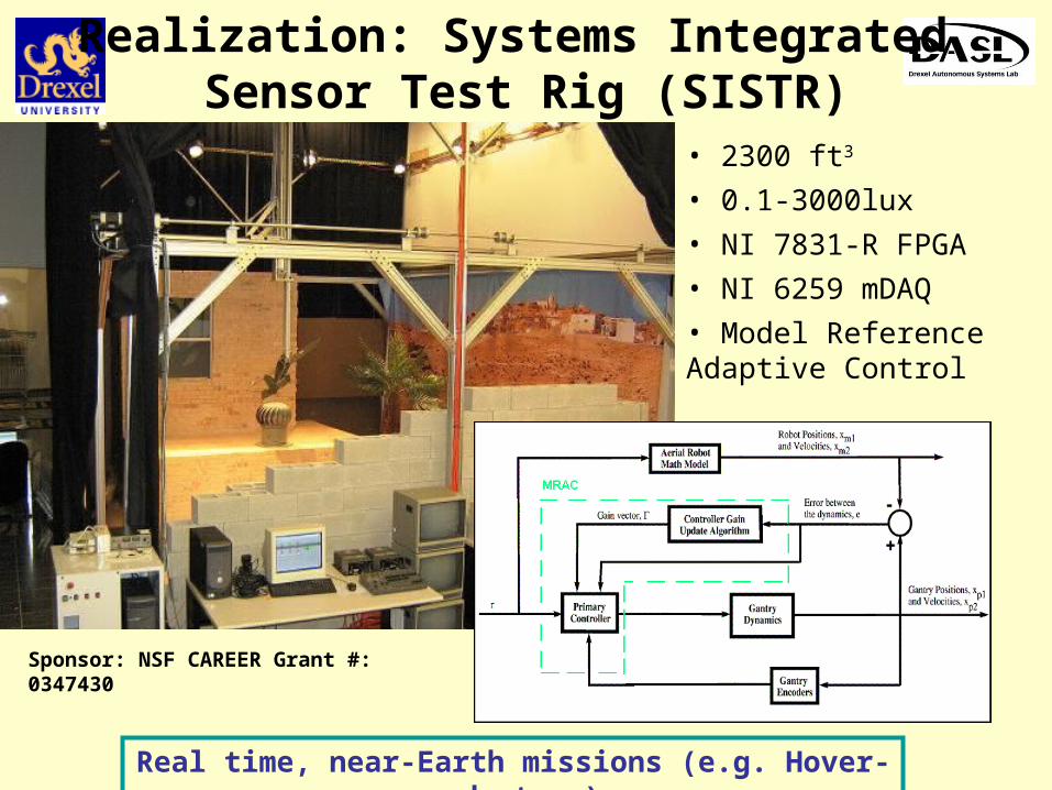
Realization: Systems Integrated Sensor Test Rig (SISTR)
• 2300 ft3
• 0.1-3000lux
• NI 7831-R FPGA
• NI 6259 mDAQ
• Model Reference Adaptive Control
Sponsor: NSF CAREER Grant #: 0347430
Real time, near-Earth missions (e.g. Hover-and-stare)
Model Reference Adaptive Control(MRAC)
• Adaptive control used to tune gains • Error = 0, plant (gantry) emulates model (aircraft)
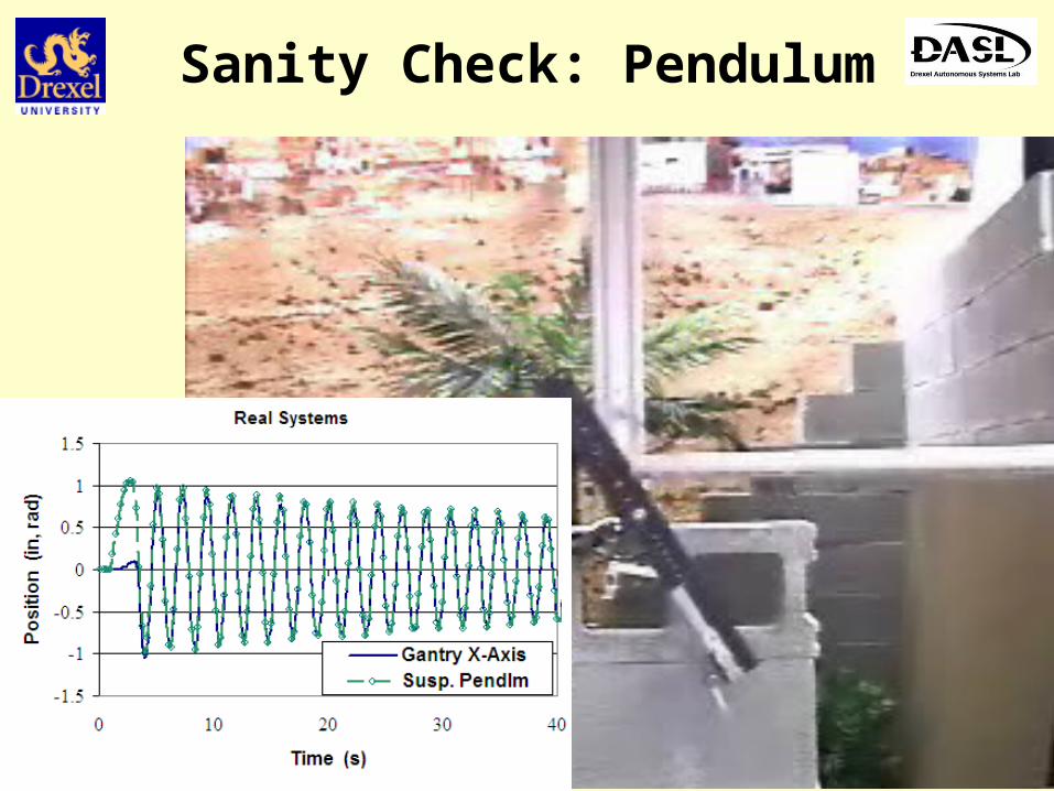
Capable of near-hover speeds with decoupled eqns of motion
Sanity Check: Pendulum
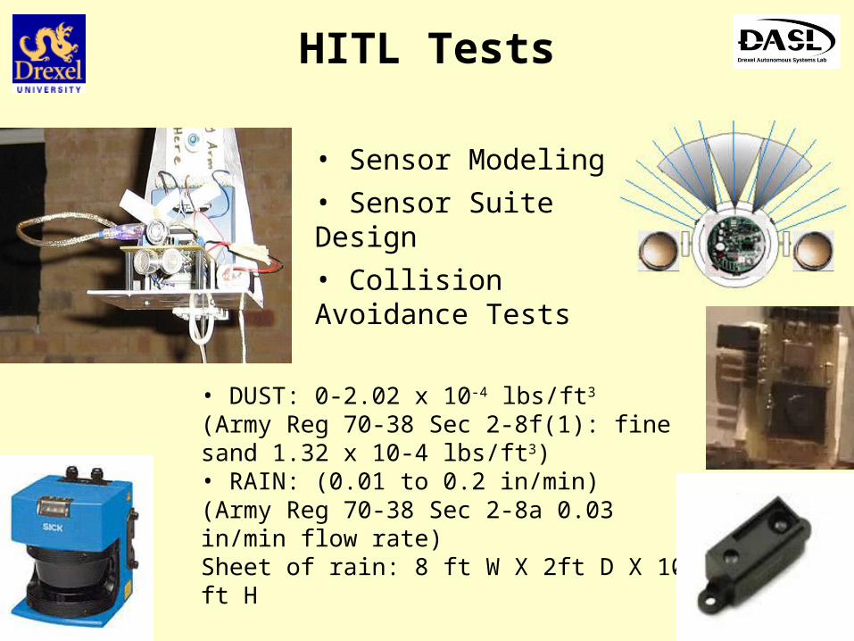
HITL Tests
• Sensor Modeling
• Sensor Suite Design
• Collision Avoidance Tests
• DUST: 0-2.02 x 10⁻⁴ lbs/ft3
(Army Reg 70-38 Sec 2-8f(1): fine sand 1.32 x 10⁻⁴ lbs/ft3)• RAIN: (0.01 to 0.2 in/min)(Army Reg 70-38 Sec 2-8a 0.03 in/min flow rate)Sheet of rain: 8 ft W X 2ft D X 10 ft H
Filling the gap: Collected sensor metrics in varying lighting, rain, fog
HITL Tests
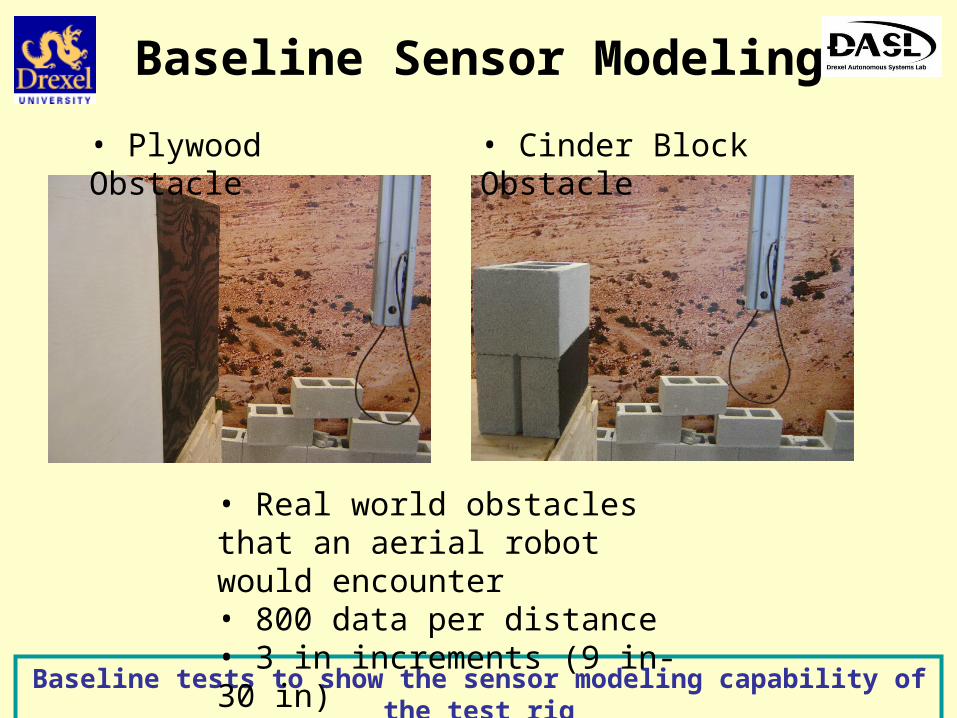
Baseline Sensor Modeling
• Plywood Obstacle
Baseline tests to show the sensor modeling capability of the test rig
• Cinder Block Obstacle
• Real world obstacles that an aerial robot would encounter• 800 data per distance • 3 in increments (9 in-30 in)
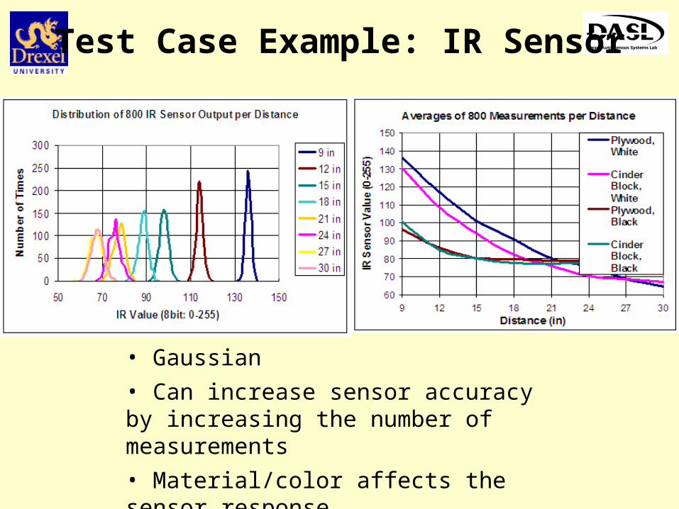
Test Case Example: IR Sensor
• Gaussian
• Can increase sensor accuracy by increasing the number of measurements
• Material/color affects the sensor response
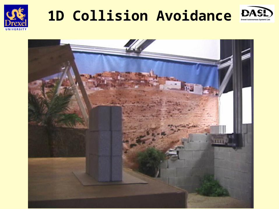
1D Collision Avoidance
Conclusions
No sensor metrics in near-Earth environments
Sensor suite design is crucial for autonomous flight
Current collision avoidance systems are not based on analytical design
Contributions
Hardware-in-the-loop test rig
Lidar, optic flow, ultrasonic, and infrared sensor tests
with real world obstacles such as trees, walls made of cinder block and plywood, poles, and cables
with controlled lighting, rain flow rate, fog and dust density conditions
FUTURE WORK
• Incorporate aircraft dynamics for dynamic tests, and collision avoidance tests
• More sensor tests with different environments, and sensors


![On The Path of Pir Sultan ? Engagement with Authority in ... · Vefa, Hacı Bektaş Veli, Yunus Emre, Mevlana, Pir Sultan Abdal and the [other] Anato-lian saints. Islam came to Anatolia](https://static.documents.pub/doc/80x56/5e56705e0cc98c0ff70e1352/on-the-path-of-pir-sultan-engagement-with-authority-in-vefa-hac-bekta.jpg)


