50
DICENTIS Conference System en Hardware Installation Manual
DICENTISConference System
en Hardware Installation Manual

DICENTIS Table of contents | en 3
Bosch Security Systems B.V. Hardware Installation Manual 2017.12 | V1.6 |
Table of contents1 Safety 42 About this manual 52.1 Intended audience 52.2 Alerts and notice signs 52.3 Copyright and disclaimer 52.4 Document history 53 System installation overview 73.1 Typical system setup 83.2 System extension 104 System installation design and planning 144.1 System capabilities 144.2 Hardware requirements 164.3 Power supply capacity calculation plan 174.3.1 Calculation using DCNM-APS(2) or DCNM-PS(2) 174.3.2 Calculation using PoE switches 194.4 Redundancy options 214.4.1 Redundant cabling for DCNM‑APS/DCNM‑PS units 224.4.2 Redundant cabling for DCNM-APS2/DCNM-PS2 units 234.4.3 Redundant server PC 255 Installation material and tools 265.1 DICENTIS System Cable Assemblies 265.2 System Cable Connectors 275.2.1 DCNM-CBCON-I Connectors for solid core cable 285.2.2 DCNM-CBCON-N Connectors for cable assembly 285.3 DCNM-CBTK System Network Cable Toolkit 295.4 DCNM-CB250-I System Installation Cable 305.5 DCNM-CBCPLR Cable couplers 315.5.1 Using a cable coupler to extend a cable 315.5.2 Using a cable coupler as a break-out box 315.5.3 Using a cable coupler as an interface between different types of cable 325.5.4 Using a cable coupler to insert power locally 346 Mechanical installation of Central Equipment 376.1 Audio processor and powering switch and Powering switch 377 Mechanical installation of Contribution Devices 407.1 DICENTIS devices 407.2 DICENTIS Microphones 447.3 DCNM-MMDSP Anti-reflection foil 467.4 DCNM-NCH Name Card Holder 468 Installation Test 47
4 en | Safety DICENTIS
2017.12 | V1.6 | Hardware Installation Manual Bosch Security Systems B.V.
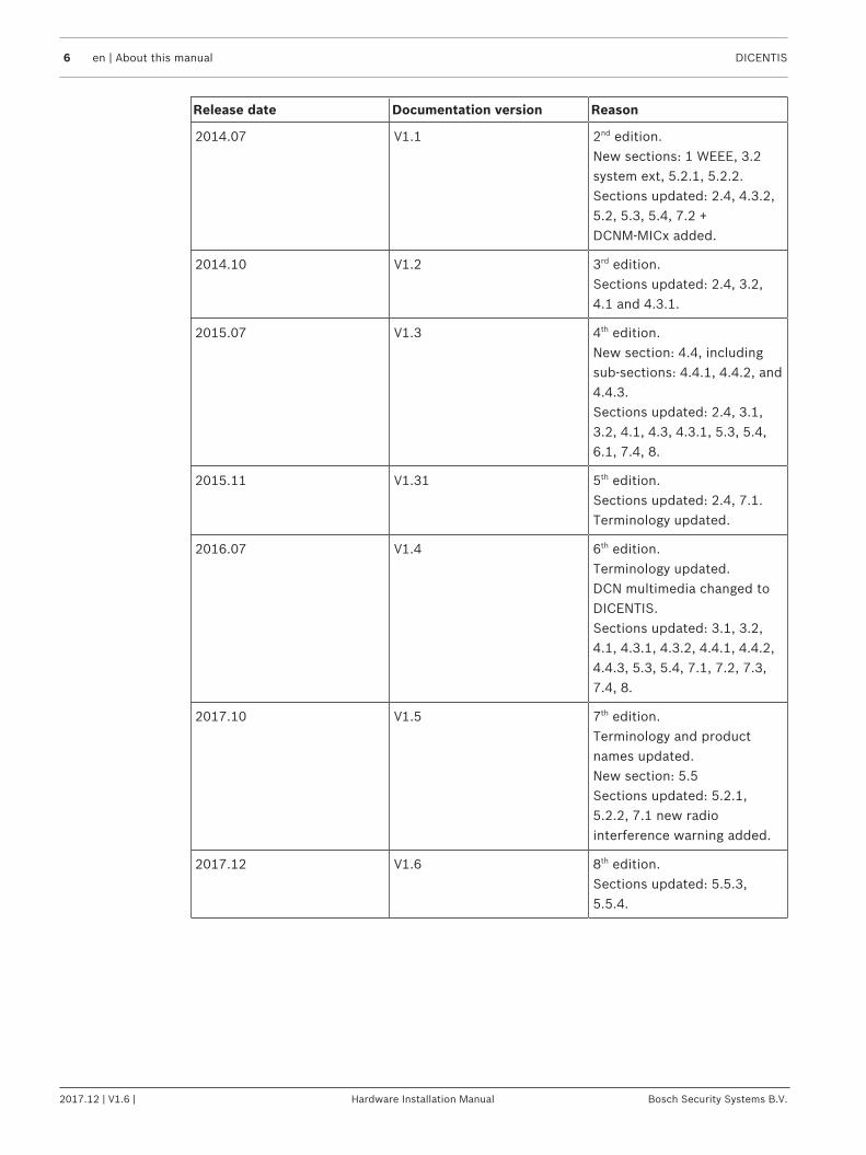
1 SafetyPrior to installing or operating products, always read the Important Safety Instructions whichare available as a separate multilingual document: Important Safety Instructions (Safety_ML).These instructions are supplied together with all equipment that can be connected to themains supply.
Safety precautionsSome of the DICENTIS Conference System products are designed to be connected to thepublic mains network.To avoid any risk of electric shock, all interventions must be carried out with disconnectedmains supply.Interventions with the equipment switched on are authorized only when it is impossible toswitch the equipment off. The operation must only be performed by qualified personnel.
Old electrical and electronic appliancesElectrical or electronic devices that are no longer serviceable must be collected separately andsent for environmentally compatible recycling (in accordance with the European WasteElectrical and Electronic Equipment Directive).To dispose of old electrical or electronic devices, you should use the return and collectionsystems put in place in the country concerned.
Class A equipment (commercial broadcasting equipment)This equipment is for professional (Class A) electromagnetic compatibility equipment. Selleror user should pay attention to this point. It is intended for use outside the home.

DICENTIS About this manual | en 5
Bosch Security Systems B.V. Hardware Installation Manual 2017.12 | V1.6 |
2 About this manualThe purpose of this manual is to provide information required for installing the DICENTISConference System.This installation manual is available as a digital document in the Adobe portable documentformat (PDF).For more information, refer to the product related information on www.boschsecurity.com
2.1 Intended audienceThis hardware installation manual is intended for installers of a DICENTIS Conference System.
2.2 Alerts and notice signsFour types of signs can be used in this manual. The type is closely related to the effect thatmay be caused if it is not observed. These signs - from least severe effect to most severeeffect - are:
Notice!Containing additional information. Usually, not observing a ‘notice’ does not result in damageto the equipment or personal injuries.
!
Caution!The equipment or the property can be damaged, or persons can be lightly injured if the alertis not observed.
!
Warning!The equipment or the property can be seriously damaged, or persons can be severely injuredif the alert is not observed.
Danger!Not observing the alert can lead to severe injuries or death.
2.3 Copyright and disclaimerAll rights reserved. No part of this document may be reproduced or transmitted in any form byany means, electronic, mechanical, photocopying, recording, or otherwise, without the priorwritten permission of the publisher. For information on getting permission for reprints andexcerpts, contact Bosch Security Systems B.V..The content and illustrations are subject to change without prior notice.
2.4 Document history
Release date Documentation version Reason
2013.08 V1.0 1st edition.
6 en | About this manual DICENTIS
2017.12 | V1.6 | Hardware Installation Manual Bosch Security Systems B.V.
Release date Documentation version Reason
2014.07 V1.1 2nd edition.New sections: 1 WEEE, 3.2system ext, 5.2.1, 5.2.2.Sections updated: 2.4, 4.3.2,5.2, 5.3, 5.4, 7.2 +DCNM‑MICx added.
2014.10 V1.2 3rd edition.Sections updated: 2.4, 3.2,4.1 and 4.3.1.
2015.07 V1.3 4th edition.New section: 4.4, includingsub-sections: 4.4.1, 4.4.2, and4.4.3.Sections updated: 2.4, 3.1,3.2, 4.1, 4.3, 4.3.1, 5.3, 5.4,6.1, 7.4, 8.
2015.11 V1.31 5th edition.Sections updated: 2.4, 7.1.Terminology updated.
2016.07 V1.4 6th edition.Terminology updated. DCN multimedia changed toDICENTIS.Sections updated: 3.1, 3.2,4.1, 4.3.1, 4.3.2, 4.4.1, 4.4.2,4.4.3, 5.3, 5.4, 7.1, 7.2, 7.3,7.4, 8.
2017.10 V1.5 7th edition.Terminology and productnames updated.New section: 5.5Sections updated: 5.2.1,5.2.2, 7.1 new radiointerference warning added.
2017.12 V1.6 8th edition.Sections updated: 5.5.3,5.5.4.

DICENTIS System installation overview | en 7
Bosch Security Systems B.V. Hardware Installation Manual 2017.12 | V1.6 |
3 System installation overviewIt is advisable to participate in the DICENTIS Conference System training before you install,configure, prepare, and operate a DICENTIS Conference System.
The DICENTIS Conference System is an IP based conference system which runs on an OMNEOcompatible Ethernet network. It is used for distributing and processing audio, video and datasignals.The DICENTIS Conference System can be quickly and easily configured as a daisy‑chainconfiguration or as a star configuration:– Daisy‑chain configuration: Uses dedicated cabling, consisting of CAT‑5e cables including
two additional power conductors (see Typical system setup, page 8).– Star configuration: Each DICENTIS device is connected with an individual standard
CAT‑5e cable. An Ethernet switch is also required for providing Power over Ethernet(PoE).
Notice!When Power over Ethernet is used, DICENTIS devices cannot be daisy‑chained. Please useunshielded cable for the DICENTIS discussion devices.
See also– Typical system setup, page 8
8 en | System installation overview DICENTIS
2017.12 | V1.6 | Hardware Installation Manual Bosch Security Systems B.V.
3.1 Typical system setup
1
8
2
4 3
9
8
8
6666
5
88
8
7
6
5.1
5.2
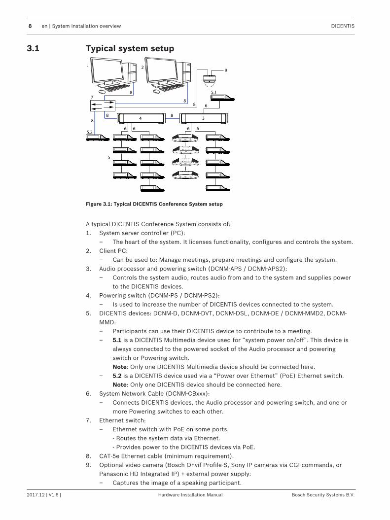
Figure 3.1: Typical DICENTIS Conference System setup
A typical DICENTIS Conference System consists of:1. System server controller (PC):
– The heart of the system. It licenses functionality, configures and controls the system.2. Client PC:
– Can be used to: Manage meetings, prepare meetings and configure the system.3. Audio processor and powering switch (DCNM-APS / DCNM-APS2):
– Controls the system audio, routes audio from and to the system and supplies powerto the DICENTIS devices.
4. Powering switch (DCNM-PS / DCNM-PS2):– Is used to increase the number of DICENTIS devices connected to the system.
5. DICENTIS devices: DCNM-D, DCNM-DVT, DCNM-DSL, DCNM-DE / DCNM-MMD2, DCNM-MMD:– Participants can use their DICENTIS device to contribute to a meeting.– 5.1 is a DICENTIS Multimedia device used for “system power on/off”. This device is
always connected to the powered socket of the Audio processor and poweringswitch or Powering switch.Note: Only one DICENTIS Multimedia device should be connected here.
– 5.2 is a DICENTIS device used via a “Power over Ethernet” (PoE) Ethernet switch.Note: Only one DICENTIS device should be connected here.
6. System Network Cable (DCNM‑CBxxx):– Connects DICENTIS devices, the Audio processor and powering switch, and one or
more Powering switches to each other.7. Ethernet switch:
– Ethernet switch with PoE on some ports. - Routes the system data via Ethernet. - Provides power to the DICENTIS devices via PoE.
8. CAT‑5e Ethernet cable (minimum requirement).9. Optional video camera (Bosch Onvif Profile-S, Sony IP cameras via CGI commands, or
Panasonic HD Integrated IP) + external power supply:– Captures the image of a speaking participant.
DICENTIS System installation overview | en 9
Bosch Security Systems B.V. Hardware Installation Manual 2017.12 | V1.6 |
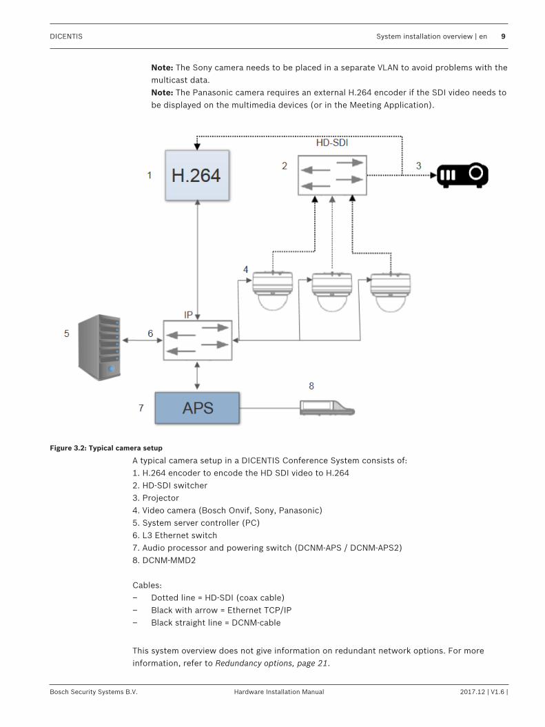
Note: The Sony camera needs to be placed in a separate VLAN to avoid problems with themulticast data.Note: The Panasonic camera requires an external H.264 encoder if the SDI video needs tobe displayed on the multimedia devices (or in the Meeting Application).
Figure 3.2: Typical camera setup
A typical camera setup in a DICENTIS Conference System consists of:1. H.264 encoder to encode the HD SDI video to H.2642. HD-SDI switcher3. Projector4. Video camera (Bosch Onvif, Sony, Panasonic)5. System server controller (PC)6. L3 Ethernet switch7. Audio processor and powering switch (DCNM-APS / DCNM-APS2)8. DCNM-MMD2
Cables:– Dotted line = HD-SDI (coax cable)– Black with arrow = Ethernet TCP/IP– Black straight line = DCNM-cable
This system overview does not give information on redundant network options. For moreinformation, refer to Redundancy options, page 21.
10 en | System installation overview DICENTIS
2017.12 | V1.6 | Hardware Installation Manual Bosch Security Systems B.V.
3.2 System extensionThe DICENTIS Conference System is scalable from small to medium to large. This sectiondescribes what a small, medium and large system is and what the requirements are for thesesystems:
A small DICENTIS Conference System (see Typical system setup, page 8) consists of:– up to 100 DICENTIS devices.– all DICENTIS devices in 1 subnet.– 1 DICENTIS Audio processor and powering switch for the audio processing.– 1 Server PC which hosts the DICENTIS services.
A medium DICENTIS Conference System consists of:– up to 450 DICENTIS nodes.
Refer to table X about the node count of DICENTIS equipment.– all DICENTIS devices in 1 subnet.– 1 DICENTIS Audio processor and powering switch for the audio processing.– 1 Server PC which hosts the DICENTIS services.– 1 ARNI-Standard to increase the size of the system.
A large DICENTIS Conference System consists of:– up to 750 DICENTIS devices.– multiple subnets connected by use of a router/L3 switch.
– Each subnet can have up to 450 DICENTIS nodes.Refer to the following table for the node count of DICENTIS equipment.
– The first subnet has:- 1 DICENTIS Audio processor and powering switch for the audio processing.- 1 Server PC which hosts the DICENTIS services.- 1 ARNI-Enterprise to increase the size of the system.
– All other subnets have 1 ARNI-Standard to increase the size of the system.Note: There is no DICENTIS Audio processor and powering switch in the othersubnets.
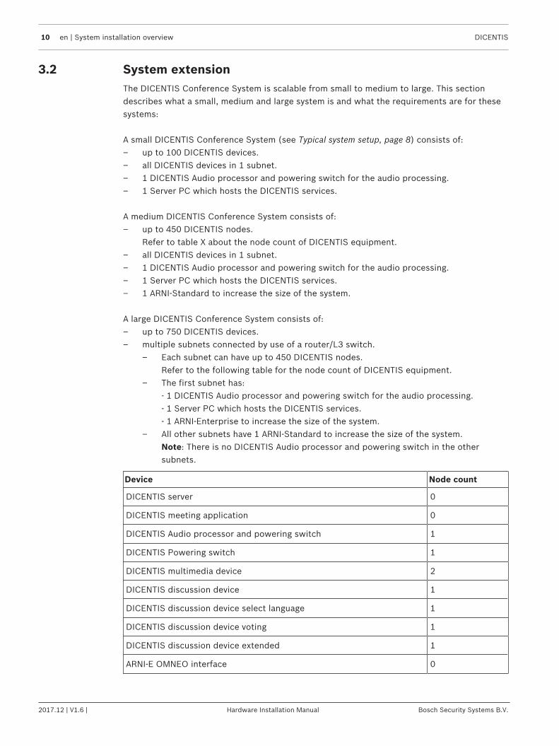
Device Node count
DICENTIS server 0
DICENTIS meeting application 0
DICENTIS Audio processor and powering switch 1
DICENTIS Powering switch 1
DICENTIS multimedia device 2
DICENTIS discussion device 1
DICENTIS discussion device select language 1
DICENTIS discussion device voting 1
DICENTIS discussion device extended 1
ARNI‑E OMNEO interface 0
DICENTIS System installation overview | en 11
Bosch Security Systems B.V. Hardware Installation Manual 2017.12 | V1.6 |
Device Node count
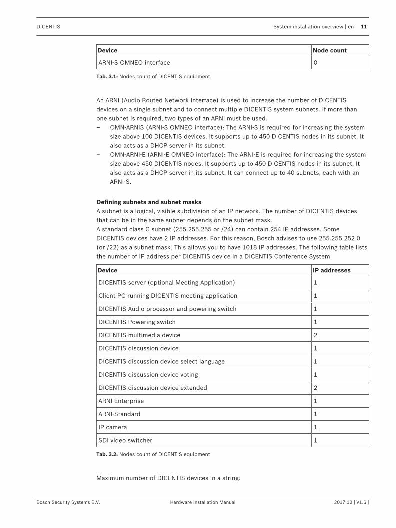
ARNI‑S OMNEO interface 0
Tab. 3.1: Nodes count of DICENTIS equipment
An ARNI (Audio Routed Network Interface) is used to increase the number of DICENTISdevices on a single subnet and to connect multiple DICENTIS system subnets. If more thanone subnet is required, two types of an ARNI must be used.– OMN-ARNIS (ARNI‑S OMNEO interface): The ARNI‑S is required for increasing the system
size above 100 DICENTIS devices. It supports up to 450 DICENTIS nodes in its subnet. Italso acts as a DHCP server in its subnet.
– OMN-ARNI‑E (ARNI‑E OMNEO interface): The ARNI‑E is required for increasing the systemsize above 450 DICENTIS nodes. It supports up to 450 DICENTIS nodes in its subnet. Italso acts as a DHCP server in its subnet. It can connect up to 40 subnets, each with anARNI‑S.
Defining subnets and subnet masksA subnet is a logical, visible subdivision of an IP network. The number of DICENTIS devicesthat can be in the same subnet depends on the subnet mask.A standard class C subnet (255.255.255 or /24) can contain 254 IP addresses. SomeDICENTIS devices have 2 IP addresses. For this reason, Bosch advises to use 255.255.252.0(or /22) as a subnet mask. This allows you to have 1018 IP addresses. The following table liststhe number of IP address per DICENTIS device in a DICENTIS Conference System.
Device IP addresses
DICENTIS server (optional Meeting Application) 1
Client PC running DICENTIS meeting application 1
DICENTIS Audio processor and powering switch 1
DICENTIS Powering switch 1
DICENTIS multimedia device 2
DICENTIS discussion device 1
DICENTIS discussion device select language 1
DICENTIS discussion device voting 1
DICENTIS discussion device extended 2
ARNI‑Enterprise 1
ARNI‑Standard 1
IP camera 1
SDI video switcher 1
Tab. 3.2: Nodes count of DICENTIS equipment
Maximum number of DICENTIS devices in a string:
12 en | System installation overview DICENTIS
2017.12 | V1.6 | Hardware Installation Manual Bosch Security Systems B.V.
– The max age timer should be set to 22 when RSTP is used for cable redundancy toprevent a defective cable or powering switch from influencing the system.
– Each time data hops from one switch to another, the age is increased by one. This timercan be reached or exceeded, because a daisy chain can be used to loop through theDICENTIS devices.
– This timer (or restriction) cannot be reached when there is no cable redundancy. This isbecause the power limitation will be reached before the max age restriction is reached.
– The timer can be reached when:– you use cable redundancy.– the system is incorrectly wired.
DICENTIS System installation overview | en 13
Bosch Security Systems B.V. Hardware Installation Manual 2017.12 | V1.6 |
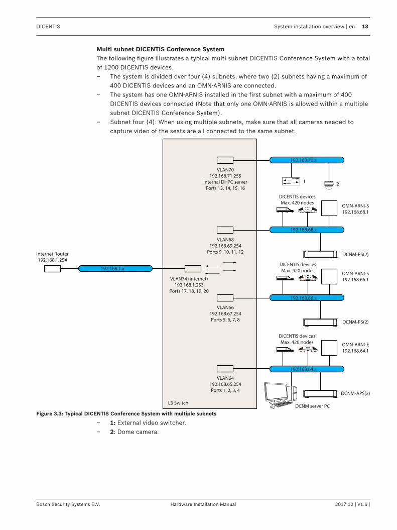
Multi subnet DICENTIS Conference SystemThe following figure illustrates a typical multi subnet DICENTIS Conference System with a totalof 1200 DICENTIS devices.– The system is divided over four (4) subnets, where two (2) subnets having a maximum of
400 DICENTIS devices and an OMN-ARNIS are connected.– The system has one OMN-ARNIS installed in the first subnet with a maximum of 400
DICENTIS devices connected (Note that only one OMN-ARNIS is allowed within a multiplesubnet DICENTIS Conference System).
– Subnet four (4): When using multiple subnets, make sure that all cameras needed tocapture video of the seats are all connected to the same subnet.
192.168.64.x
OMN-ARNI-E
192.168.64.1
VLAN64
192.168.65.254
Ports 1, 2, 3, 4
L3 Switch
VLAN66
192.168.67.254
Ports 5, 6, 7, 8
VLAN74 (internet)
192.168.1.253
Ports 17, 18, 19, 20
VLAN68
192.168.69.254
Ports 9, 10, 11, 12
VLAN70
192.168.71.255
Internal DHPC server
Ports 13, 14, 15, 16
Internet Router
192.168.1.254
DCNM-APS(2)
DCNM server PC
DCNM-PS(2)
DICENTIS devices
Max. 420 nodes
DICENTIS devices
Max. 420 nodes
DICENTIS devices
Max. 420 nodes
DCNM-PS(2)
OMN-ARNI-S
192.168.66.1
OMN-ARNI-S
192.168.68.1
192.168.66.x
192.168.1.x
192.168.68.x
192.168.70.x
12
Figure 3.3: Typical DICENTIS Conference System with multiple subnets
– 1: External video switcher.– 2: Dome camera.
14 en | System installation design and planning DICENTIS
2017.12 | V1.6 | Hardware Installation Manual Bosch Security Systems B.V.
4 System installation design and planningBefore you start to install system devices and connect system cabling, you should make asystem design and planning:– Familiarize yourself with the product and system capabilities.– Make a cable (connection) plan:
– Calculate the system network cable length.– Calculate the system power consumption.– Calculate the required power capacity of the system.
Notice!The DICENTIS Conference System uses the RSTP protocol when redundant cabling mode isenabled. If the DICENTIS Conference System needs to be connected with the locally presentnetwork, please consult the local IT department before continuing with the installationdesign.
Notice!Make sure that the cable lengths and power consumptions do not exceed the specifications.Not doing so will result in malfunctioning at any moment of the DICENTIS Conference Systemand products.
4.1 System capabilitiesThe capability of the DICENTIS Conference System and DICENTIS products depends on:– The lengths of the system network cables.– The number of connected devices.– The system power supply capacity.
Cable lengthSystem network cables (DCNM‑CBxx-I) lengths (2, 5, 10 or 25 m) have a direct effect on theavailable power supply capacity. The longer the system network cable, the less power supplycapacity is available to drive the connected devices. Therefore, choose the lengths of thesystem network cables carefully.
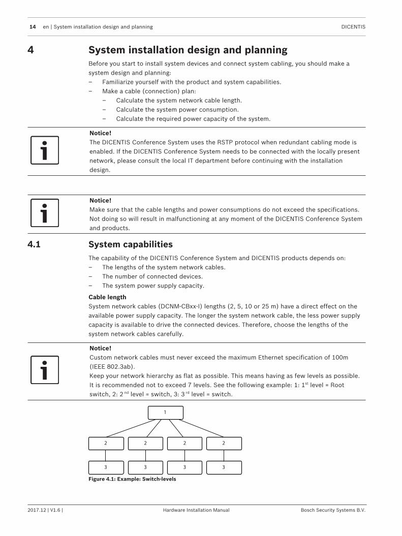
Notice!Custom network cables must never exceed the maximum Ethernet specification of 100m(IEEE 802.3ab).Keep your network hierarchy as flat as possible. This means having as few levels as possible.It is recommended not to exceed 7 levels. See the following example: 1: 1st level = Rootswitch, 2: 2 nd level = switch, 3: 3 rd level = switch.
1
2 2 2 2
3 3 3 3
Figure 4.1: Example: Switch-levels

DICENTIS System installation design and planning | en 15
Bosch Security Systems B.V. Hardware Installation Manual 2017.12 | V1.6 |
Power supply capacityThe total system network cable length and connected devices determine the required powersupply capacity. The power within the DICENTIS Conference System is supplied by:– The Audio processor and powering switch and the Powering switch, or– Off‑the‑shelf PoE Ethernet switches.
Calculation toolThe calculation tool can be used to calculate the total power capacity of the system. Thismakes the design and planning of the DICENTIS Conference System easier. The calculationtool uses the power consumption of the devices and the system network cable lengths tocalculate the needed system power supply capacity.The calculation tool is on the DVD supplied with the Audio processor and powering switch andis part of the DICENTIS software DCNM.iso file. The DCNM.iso file can be downloaded fromthe Bosch website at: https://licensing.boschsecurity.com/software
16 en | System installation design and planning DICENTIS
2017.12 | V1.6 | Hardware Installation Manual Bosch Security Systems B.V.
4.2 Hardware requirementsSwitchesThe following minimal requirements apply to switches:– 1 Gbit or higher with hardware switching capabilities.– Quality of Service through differentiated services with 4 or more output queues and strict
priority packet scheduling.– (Optional) IGMPv3 or IGMPv2 snooping. To optimize bandwidth usage, IGMP snooping
can be used. This is useful in systems with >10 multicast streams, although not absolutelyrequired. Sufficient performance for handling a large number of IGMP query responses,depending on the number of (directly or indirectly) connected devices to that switch.Hardware support for IGMP is strongly recommended.
– VLAN separation is recommended instead of IGMP, because most switches are unable tohandle the multicast changes in the system. Filtering multicast data may be necessary forsome devices, such as 100 Mb devices (Sony cameras, TVOne, AMX, and others).
– (Rapid) Spanning tree needs to be DISABLED for optimal operation. When enabled, it cancause slow connections to the switch. In case of a redundant network where you wouldrequire RSTP, configure the switch to use the “portfast” mode.
– (Optional) SNMPv3 support for switch supervision purposes.
RoutersThe following minimal requirements apply to routers:– 1 Gbit or higher Ethernet ports.– Supports PIM‑DM or Bidirectional PIM.– Performs IP routing in hardware (i.e. a ‘layer 3 switch’) to minimize the routing delay.– Packet forwarding rate > 1,000,000 packets per second per port (e.g. 8 Mpps for an
8‑port router).– Non-blocking backplane per switching port, i.e. 2 Gbit per port (e.g. 16 Gbps for an 8‑port
router).– MAC address table of at least 1000 addresses per directly connected subnet.

DICENTIS System installation design and planning | en 17
Bosch Security Systems B.V. Hardware Installation Manual 2017.12 | V1.6 |
4.3 Power supply capacity calculation planHow to start
Notice!It is advisable to use the power calculation tool. The calculation tool is on the DVD suppliedwith the Audio processor and powering switch and is also part of the DICENTIS softwareDCNM.iso file, which can be downloaded from the Bosch website at: https://licensing.boschsecurity.com/software
Decide how to supply power to the DICENTIS devices:– Using the Audio processor and powering switch and one or more Powering switches.– Using one or more PoE Ethernet switches.If you want to use PoE Ethernet switches, continue with chapter Calculation using PoEswitches, page 19.
See also– Calculation using DCNM-APS(2) or DCNM-PS(2), page 17– Installation material and tools, page 26
4.3.1 Calculation using DCNM-APS(2) or DCNM-PS(2)
Notice!If you want to use customized cables, or a more accurate power supply capacity calculationplan is needed, you should use the power calculation tool.
To calculate the total power supply capacity:1. Count all DICENTIS devices.2. Know the exact location where the devices are installed.3. Count each system network cable of the same length.
Device type Power consumption (Watts)
DCNM-D 3.1
DCNM-DSL 3.6
DCNM-DVT 3.7
DCNM-DE 5.00
DCNM-MMD 11.30
DCNM-MMD2 12.00
DCNM‑CB02-I 1.19
DCNM‑CB05-I 2.43
DCNM‑CB10-I 4.50
DCNM‑CB25-I 10.71
Tab. 4.3: Power consumption (Watts)
18 en | System installation design and planning DICENTIS
2017.12 | V1.6 | Hardware Installation Manual Bosch Security Systems B.V.
Ordering number Cable lengths
m ft
DCNM-CB02-I 2 6.56
DCNM-CB05-I 5 16.40
DCNM-CB10-I 10 32.81
DCNM-CB25-I 25 82.02
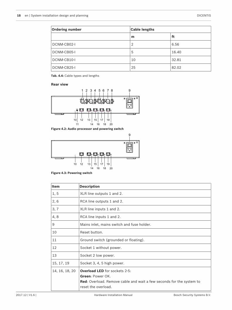
Tab. 4.4: Cable types and lengths
Rear view
10 12 13 15 17 19
11 14 16 18 20
1 2 3 4 5 6 7 8 9
Figure 4.2: Audio processor and powering switch
10 12 13 15 17
14 16 18
19
20
9
Figure 4.3: Powering switch
Item Description
1, 5 XLR line outputs 1 and 2.
2, 6 RCA line outputs 1 and 2.
3, 7 XLR line inputs 1 and 2.
4, 8 RCA line inputs 1 and 2.
9 Mains inlet, mains switch and fuse holder.
10 Reset button.
11 Ground switch (grounded or floating).
12 Socket 1 without power.
13 Socket 2 low power.
15, 17, 19 Socket 3, 4, 5 high power.
14, 16, 18, 20 Overload LED for sockets 2‑5:Green: Power OK.Red: Overload. Remove cable and wait a few seconds for the system toreset the overload.
DICENTIS System installation design and planning | en 19
Bosch Security Systems B.V. Hardware Installation Manual 2017.12 | V1.6 |
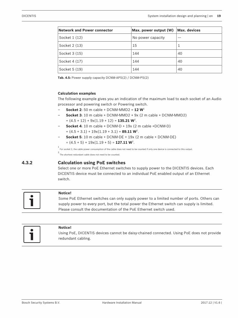
Network and Power connector Max. power output (W) Max. devices
Socket 1 (12) No power capacity ---
Socket 2 (13) 15 1
Socket 3 (15) 144 40
Socket 4 (17) 144 40
Socket 5 (19) 144 40
Tab. 4.5: Power supply capacity DCNM‑APS(2) / DCNM‑PS(2)
Calculation examplesThe following example gives you an indication of the maximum load to each socket of an Audioprocessor and powering switch or Powering switch.– Socket 2: 50 m cable + DCNM-MMD2 = 12 W1
– Socket 3: 10 m cable + DCNM-MMD2 + 9x (2 m cable + DCNM-MMD2)= (4.5 + 12) + 9x(1.19 + 12) = 135.21 W2.
– Socket 4: 10 m cable + DCNM-D + 19x (2 m cable +DCNM-D)= (4.5 + 3.1) + 19x(1.19 + 3.1) = 89.11 W2.
– Socket 5: 10 m cable + DCNM-DE + 19x (2 m cable + DCNM-DE) = (4.5 + 5) + 19x(1.19 + 5) = 127.11 W2.
1 For socket 2, the cable power consumption of the cable does not need to be counted if only one device is connected to this output.
2 The shortest redundant cable does not need to be counted.
4.3.2 Calculation using PoE switchesSelect one or more PoE Ethernet switches to supply power to the DICENTIS devices. EachDICENTIS device must be connected to an individual PoE enabled output of an Ethernetswitch.
Notice!Some PoE Ethernet switches can only supply power to a limited number of ports. Others cansupply power to every port, but the total power the Ethernet switch can supply is limited.Please consult the documentation of the PoE Ethernet switch used.
Notice!Using PoE, DICENTIS devices cannot be daisy‑chained connected. Using PoE does not provideredundant cabling.

20 en | System installation design and planning DICENTIS
2017.12 | V1.6 | Hardware Installation Manual Bosch Security Systems B.V.
2
1
Figure 4.4: Bottom view DICENTIS devices (DCNM-MMD / DCNM-MMD2)
2
1
Figure 4.5: Bottom view DICENTIS devices (DCNM-D / DCNM-DVT / DCNM-DSL / DCNM-DE)
Item Description
1 Network connector
2 Network/PoE connector
DICENTIS System installation design and planning | en 21
Bosch Security Systems B.V. Hardware Installation Manual 2017.12 | V1.6 |
4.4 Redundancy optionsDICENTIS Conference Systems can be created with network redundancy. This ensures that thesystem will continue to work if:– a network cable is defective or accidentally disconnected.– one of the components fails.
Different levels of redundancy can be created in the system depending on:– the type of unit used in the system (DCNM-APS / DCNM-PS or DCNM-APS2 / DCNM-PS2)– the number of redundant components used in the system.– the amount of redundant network cabling.
The following sections explain the redundancy options that can be used when designing yourDICENTIS Conference System. Each option can be combined in the DICENTIS ConferenceSystem, providing you observe the redundant cabling limitations. Refer to:– Redundant cabling for DCNM‑APS/DCNM‑PS units, page 22.– Redundant cabling for DCNM-APS2/DCNM-PS2 units, page 23.– Redundant server PC, page 25.
Notice!Rapid Spanning Tree Protocol (RSTP) must be enabled in the DICENTIS Conference Systemfor these redundancy options to work correctly.
22 en | System installation design and planning DICENTIS
2017.12 | V1.6 | Hardware Installation Manual Bosch Security Systems B.V.
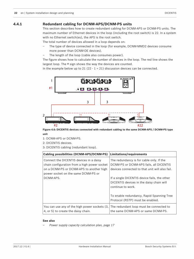
4.4.1 Redundant cabling for DCNM‑APS/DCNM‑PS unitsThis section describes how to create redundant cabling for DCNM-APS or DCNM-PS units. Themaximum number of Ethernet devices in the loop (including the root switch) is 22. In a systemwith no Ethernet switch(es), the APS is the root switch.The total number of devices allowed in a loop depends on:– The type of device connected in the loop (for example, DCNM-MMD2 devices consume
more power than DCNM-DE devices).– The length of the loop (cable also consumes power).The figure shows how to calculate the number of devices in the loop. The red line shows thelargest loop. The # sign shows the way the devices are counted.In the example below up to 21 (22 - 1 = 21) discussion devices can be connected.
1
2
3 3
#1
#2 #22
Figure 4.6: DICENTIS devices connected with redundant cabling to the same DCNM-APS / DCNM-PS type
unit
1: DCNM-APS or DCNM-PS.2: DICENTIS devices.3: DICENTIS cabling (redundant loop).
Cabling possibilities (DCNM‑APS/DCNM‑PS) Limitations/requirements
Connect the DICENTIS devices in a daisychain configuration from a high power socketon a DCNM-PS or DCNM-APS to another highpower socket on the same DCNM-PS orDCNM-APS.
The redundancy is for cable only. If theDCNM-PS or DCNM-APS fails, all DICENTISdevices connected to that unit will also fail.
If a single DICENTIS device fails, the otherDICENTIS devices in the daisy chain willcontinue to work.
To enable redundancy, Rapid Spanning TreeProtocol (RSTP) must be enabled.
You can use any of the high power sockets (3,4, or 5) to create the daisy chain.
The redundant loop must be connected tothe same DCNM-APS or same DCNM-PS.
See also– Power supply capacity calculation plan, page 17

DICENTIS System installation design and planning | en 23
Bosch Security Systems B.V. Hardware Installation Manual 2017.12 | V1.6 |
4.4.2 Redundant cabling for DCNM-APS2/DCNM-PS2 unitsThis section describes how to create redundant cabling for DCNM-APS2 / DCNM-PS2 typeunits. The maximum number of Ethernet devices in the largest possible loop (including theroot switch) is 22. In a system with no Ethernet switch(es), the APS is the root switch.The total number of devices allowed in a loop depends on:– The type of device connected in the loop (for example, DCNM-MMD2 devices consume
more power than DCNM-DE devices).– The length of the loop (cable also consumes power).The figure shows how to calculate the number of devices in the loop. The red line shows thelargest loop. The # sign shows the way the devices are counted.In the example below up to 19 (22 - 3 = 19) discussion devices can be connected.
#1
#2 #22
#3 #21
1
3 4
5 5
5 5
5 5
4 4
2
Figure 4.7: DICENTIS discussion devices connected with redundant cabling between DCNM-PS2 / DCNM-
APS2 type units
1: DICENTIS system/client PC.2: Network switch (with optional redundant power supply)3: DCNM-APS24: DCNM-PS25: DICENTIS cabling (redundant loop)
Cabling possibilities (DCNM-APS2/DCNM-PS2)
Limitations/requirements
Create a redundant loop by connecting theDICENTIS devices in a daisy chainconfiguration from a high power socket on aDCNM-PS2 / DCNM-APS2 to a high powersocket on another DCNM-PS2.
The redundant loop between two DCNM-PS2units is for power and signal. If one of theDCNM-PS2 units fails, the other DCNM-PS2unit will supply power and signal to theDICENTIS devices in the daisy chain.
The redundancy is for cable only. If theDCNM-PS or DCNM-APS fails, all DICENTISdevices connected to that unit will also fail.
To enable redundancy:– Rapid Spanning Tree Protocol (RSTP)
must be enabled in the DICENTISConference System.
– a network switch with redundant powersupply, should be connected to theDCNM-PS2 / DCNM-APS2 units, asshown in the previous figure.

24 en | System installation design and planning DICENTIS
2017.12 | V1.6 | Hardware Installation Manual Bosch Security Systems B.V.
Cabling possibilities (DCNM-APS2/DCNM-PS2)
Limitations/requirements
You can use any of the high power sockets (3,4, or 5) on either of the DCNM-PS2 units tocreate the daisy chain/redundant loop.For example, high power socket 3 on one unitcan be connected to high power socket 4 onanother unit.
Note: The redundant loop must be connectedto another DCNM-PS2 type unit. You cannotuse DCNM-PS / DCNM-APS type units tocreate redundant loops for power.
You can create a redundant loop for signalonly, by connecting the DICENTIS devices in adaisy chain configuration to the same DCNM-PS2 or DCNM-APS2, although this is notrecommended.The DCNM-PS2 unit is designed to reducecost of ownership, for example, by allowing amaximum of three redundant loops to beconnected between two DCNM-PS2 units.
The redundant loop will function in the sameway as a DCNM-PS / DCNM-APS type unit.Refer to Redundant cabling for DCNM‑APS/DCNM‑PS units, page 22.
Notice!Rapid Spanning Tree Protocol (RSTP) must be enabled in the DICENTIS Conference Systemfor these redundancy options to work correctly.
See also– Power supply capacity calculation plan, page 17
DICENTIS System installation design and planning | en 25
Bosch Security Systems B.V. Hardware Installation Manual 2017.12 | V1.6 |
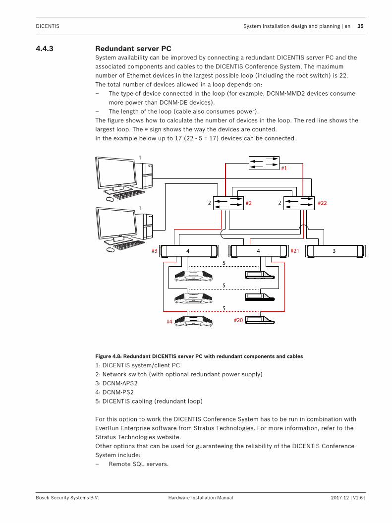
4.4.3 Redundant server PCSystem availability can be improved by connecting a redundant DICENTIS server PC and theassociated components and cables to the DICENTIS Conference System. The maximumnumber of Ethernet devices in the largest possible loop (including the root switch) is 22.The total number of devices allowed in a loop depends on:– The type of device connected in the loop (for example, DCNM-MMD2 devices consume
more power than DCNM-DE devices).– The length of the loop (cable also consumes power).The figure shows how to calculate the number of devices in the loop. The red line shows thelargest loop. The # sign shows the way the devices are counted.In the example below up to 17 (22 - 5 = 17) devices can be connected.
#4 #20
#2
#3 #21
#22
#1
1
1
4 4
5
5
5
3
22
Figure 4.8: Redundant DICENTIS server PC with redundant components and cables
1: DICENTIS system/client PC2: Network switch (with optional redundant power supply)3: DCNM-APS24: DCNM-PS25: DICENTIS cabling (redundant loop)
For this option to work the DICENTIS Conference System has to be run in combination withEverRun Enterprise software from Stratus Technologies. For more information, refer to theStratus Technologies website.Other options that can be used for guaranteeing the reliability of the DICENTIS ConferenceSystem include:– Remote SQL servers.
26 en | Installation material and tools DICENTIS
2017.12 | V1.6 | Hardware Installation Manual Bosch Security Systems B.V.
5 Installation material and toolsThis section describes installation material such as cables, connectors and tools.
Recommedations– Always use manufacturer specified installation products, materials and tools.– In general, use different cable ducts for the system network cables, audio cables and
mains supply cables.– In public areas where people can touch or move above the connectors and cables, use
metal protection covers.
!
Warning!Do not exceed the bend limitations of system network cables (DCNM‑CBxxx):The minimum bend radius of the system network cable is a 35 mm radius.
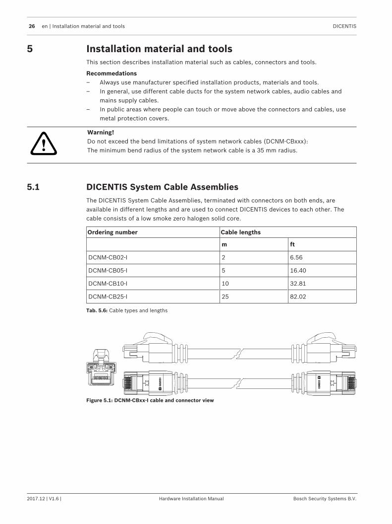
5.1 DICENTIS System Cable AssembliesThe DICENTIS System Cable Assemblies, terminated with connectors on both ends, areavailable in different lengths and are used to connect DICENTIS devices to each other. Thecable consists of a low smoke zero halogen solid core.
Ordering number Cable lengths
m ft
DCNM-CB02-I 2 6.56
DCNM-CB05-I 5 16.40
DCNM-CB10-I 10 32.81
DCNM-CB25-I 25 82.02
Tab. 5.6: Cable types and lengths
Figure 5.1: DCNM-CBxx-I cable and connector view

DICENTIS Installation material and tools | en 27
Bosch Security Systems B.V. Hardware Installation Manual 2017.12 | V1.6 |
5.2 System Cable ConnectorsThe connectors are used to make your own system network cables or to replace a connector.Two types of system cable connectors are available: DCNM-CBCON-I Connectors for solid corecable, page 28 and DCNM-CBCON-N Connectors for cable assembly, page 28.
!
Caution!Both connector types look similar but are different! So, only use the right type of connectorwith the right type of system cable.
12
3
5
79
8
6
4
43
1
5
6
7
9
8
12
3
5
79
8
6
4
43
1
5
6
7
9
8
Figure 5.2: DCNM-CBCON Front and exploded view
Item Description
1 Strain relief boot
2 Ferrule
3 Plug connector shield
4 Power contacts (Qty: 2)
5 Load bar
6 Power contact cavity (2 places)
7 Housing
8 Locking latch
9 Signal contact cavity (8 Places)
See also– DICENTIS System Cable Assemblies, page 26– DCNM-CB250-I System Installation Cable, page 30– DCNM-CBTK System Network Cable Toolkit, page 29
28 en | Installation material and tools DICENTIS
2017.12 | V1.6 | Hardware Installation Manual Bosch Security Systems B.V.
5.2.1 DCNM-CBCON-I Connectors for solid core cableThe DICENTIS Connectors for solid core cable 50 pcs, DCNM‑CBCON‑I can only be used withthe DCNM-CB250-I System Installation Cable, page 30 by using the DCNM-CBTK SystemNetwork Cable Toolkit, page 29. Compatible with solid core cables: DCNM-CB02-I, DCNM-CB05-I, DCNM-CB10-I, DCNM-CB25-I, DCNM-CB250-I, DCNM-CB250.
5.2.2 DCNM-CBCON-N Connectors for cable assemblyThe DICENTIS Connectors for cable assembly, DCNM‑CBCON‑N can only be used with theDICENTIS System Cable Assemblies, page 26 by using the DCNM-CBTK System Network CableToolkit, page 29. Compatible with twisted core cables: DCNM-CB02, DCNM-CB05, DCNM-CB10, DCNM-CB25, DCNM-CB02B, DCNM-CB05B, DCNM-CB10B, DCNM-CB25B, DCNM-CB250B.

DICENTIS Installation material and tools | en 29
Bosch Security Systems B.V. Hardware Installation Manual 2017.12 | V1.6 |
5.3 DCNM-CBTK System Network Cable ToolkitThe system network cable toolkit is used to connect the System Cable Connectors, page 27 tothe DCNM-CB250-I System Installation Cable, page 30 or DICENTIS System Cable Assemblies,page 26.
21
Item Description
1 Power wiring tool.
2 Signal wiring tool.
Tab. 5.7: Toolkit content
Notice!Please consult the “custom length for system network cables” section on the DVD, which canbe downloaded at: https://licensing.boschsecurity.com/software
30 en | Installation material and tools DICENTIS
2017.12 | V1.6 | Hardware Installation Manual Bosch Security Systems B.V.
5.4 DCNM-CB250-I System Installation CableThe system installation cable, without connectors, is available in a length of 250 meters and isused for making your own system network cable. Refer also to the sections System CableConnectors, page 27, DCNM-CBCON-I Connectors for solid core cable, page 28 and DCNM-CBTKSystem Network Cable Toolkit, page 29.
Notice!The maximum system network cable length is: 100 m / 328,9 ft.
Notice!Please consult the “custom length for system network cables” section on the DVD, which canbe downloaded at: https://licensing.boschsecurity.com/software
See also– System Cable Connectors, page 27
DICENTIS Installation material and tools | en 31
Bosch Security Systems B.V. Hardware Installation Manual 2017.12 | V1.6 |
5.5 DCNM-CBCPLR Cable couplersCable couplers can be used:– to extend cables,– in a floor pod as break-out box,– as an interface between DICENTIS cable and “standard” CAT-5E cable combined with a
separate power cable,– to insert power locally to the participant devices,– to switch the system on by using two cable couplers and a switch.Cable couplers are delivered in a box that contains 6 cable couplers. They can be used for alltypes of DICENTIS cables.
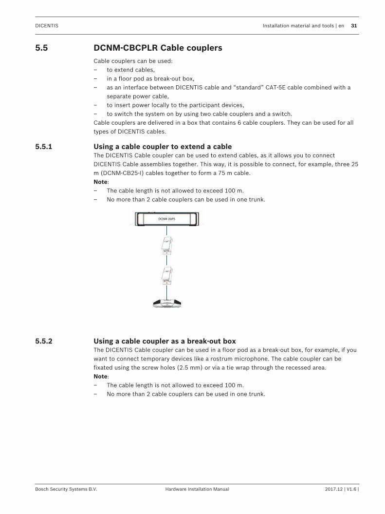
5.5.1 Using a cable coupler to extend a cableThe DICENTIS Cable coupler can be used to extend cables, as it allows you to connectDICENTIS Cable assemblies together. This way, it is possible to connect, for example, three 25m (DCNM-CB25-I) cables together to form a 75 m cable.Note:– The cable length is not allowed to exceed 100 m.– No more than 2 cable couplers can be used in one trunk.
DCNM-(A)PSDCNM-(A)PS
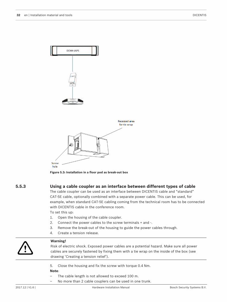
5.5.2 Using a cable coupler as a break-out boxThe DICENTIS Cable coupler can be used in a floor pod as a break-out box, for example, if youwant to connect temporary devices like a rostrum microphone. The cable coupler can befixated using the screw holes (2.5 mm) or via a tie wrap through the recessed area.Note:– The cable length is not allowed to exceed 100 m.– No more than 2 cable couplers can be used in one trunk.
32 en | Installation material and tools DICENTIS
2017.12 | V1.6 | Hardware Installation Manual Bosch Security Systems B.V.
DCNM-(A)PS
Figure 5.3: Installation in a floor pod as break-out box
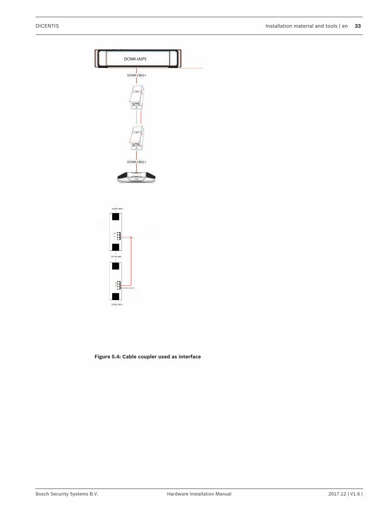
5.5.3 Using a cable coupler as an interface between different types of cableThe cable coupler can be used as an interface between DICENTIS cable and “standard”CAT-5E cable, optionally combined with a separate power cable. This can be used, forexample, when standard CAT-5E cabling coming from the technical room has to be connectedwith DICENTIS cable in the conference room.To set this up:1. Open the housing of the cable coupler.2. Connect the power cables to the screw terminals + and -.3. Remove the break-out of the housing to guide the power cables through.4. Create a tension release.
!
Warning!Risk of electric shock. Exposed power cables are a potential hazard. Make sure all powercables are securely fastened by fixing them with a tie wrap on the inside of the box (seedrawing ‘Creating a tension relief’).
5. Close the housing and fix the screw with torque 0.4 Nm.Note:– The cable length is not allowed to exceed 100 m.– No more than 2 cable couplers can be used in one trunk.
DICENTIS Installation material and tools | en 33
Bosch Security Systems B.V. Hardware Installation Manual 2017.12 | V1.6 |
DCNM-CB02-I
DCNM-CB02-I
DCNM-(A)PS
CAT-5E cable
DCNM-CB02-I
DCNM-CB02-I
Figure 5.4: Cable coupler used as interface

34 en | Installation material and tools DICENTIS
2017.12 | V1.6 | Hardware Installation Manual Bosch Security Systems B.V.
Figure 5.5: Creating a tension relief, tie wrap prevents the power cables from being pulled out accidentally.
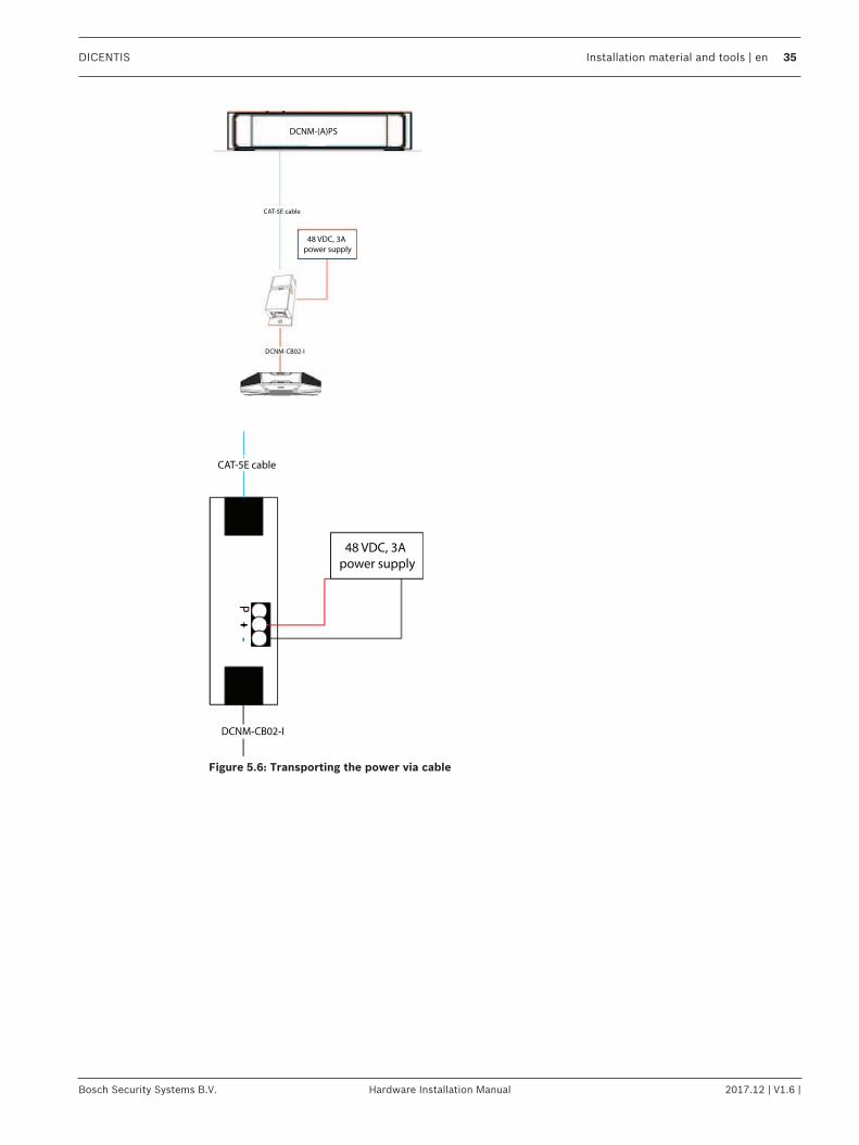
5.5.4 Using a cable coupler to insert power locallyThe cable coupler can be used to insert a local power supply, enabling you to place a third-party 48 VDC power close to the participant devices.To set this up:1. Open the housing of the cable coupler.2. Connect the power cables to the screw terminals + and -.3. Remove the break-out of the housing to guide the power cables through.4. Create a tension release.
!
Warning!Risk of electric shock. Exposed power cables are a potential hazard. Make sure all powercables are securely fastened by fixing them with a tie wrap on the inside of the box (seedrawing ‘Creating a tension relief’).
5. Close the housing and fix the screw with torque 0.4 Nm.Note:– The maximum power ratings are 48 VDC and 3A.– The maximum distance between the (A)PS and the conference device is 100 m due to the
Ethernet properties.
DICENTIS Installation material and tools | en 35
Bosch Security Systems B.V. Hardware Installation Manual 2017.12 | V1.6 |
DCNM-(A)PS
CAT-5E cable
DCNM-CB02-I
48 VDC, 3A
power supply
CAT-5E cable
DCNM-CB02-I
48 VDC, 3A
power supply
Figure 5.6: Transporting the power via cable

36 en | Installation material and tools DICENTIS
2017.12 | V1.6 | Hardware Installation Manual Bosch Security Systems B.V.
Figure 5.7: Creating a tension relief, tie wrap prevents the power cables from being pulled out accidentally.
DICENTIS Mechanical installation of Central Equipment | en 37
Bosch Security Systems B.V. Hardware Installation Manual 2017.12 | V1.6 |
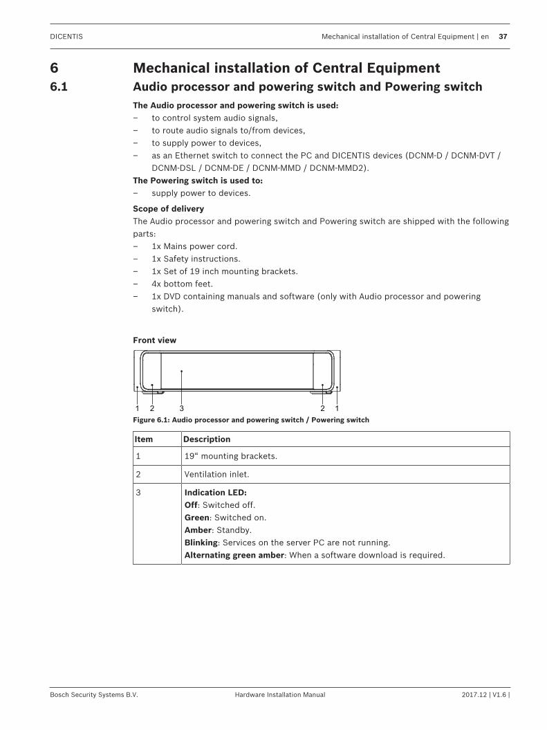
6 Mechanical installation of Central Equipment6.1 Audio processor and powering switch and Powering switch
The Audio processor and powering switch is used:– to control system audio signals,– to route audio signals to/from devices,– to supply power to devices,– as an Ethernet switch to connect the PC and DICENTIS devices (DCNM-D / DCNM-DVT /
DCNM-DSL / DCNM-DE / DCNM-MMD / DCNM-MMD2).The Powering switch is used to:– supply power to devices.
Scope of deliveryThe Audio processor and powering switch and Powering switch are shipped with the followingparts:– 1x Mains power cord.– 1x Safety instructions.– 1x Set of 19 inch mounting brackets.– 4x bottom feet.– 1x DVD containing manuals and software (only with Audio processor and powering
switch).
Front view
1 2 2 13
Figure 6.1: Audio processor and powering switch / Powering switch
Item Description
1 19“ mounting brackets.
2 Ventilation inlet.
3 Indication LED:Off: Switched off.Green: Switched on.Amber: Standby.Blinking: Services on the server PC are not running.Alternating green amber: When a software download is required.

38 en | Mechanical installation of Central Equipment DICENTIS
2017.12 | V1.6 | Hardware Installation Manual Bosch Security Systems B.V.
Rear view
10 12 13 15 17 19
11 14 16 18 20
1 2 3 4 5 6 7 8 9
Figure 6.2: Audio processor and powering switch
10 12 13 15 17
14 16 18
19
20
9
Figure 6.3: Powering switch
Item Description
1, 5 XLR line outputs 1 and 2.
2, 6 RCA line outputs 1 and 2.
3, 7 XLR line inputs 1 and 2.
4, 8 RCA line inputs 1 and 2.
9 Mains inlet, mains switch and fuse holder.
10 Reset button.
11 Ground switch (grounded or floating).
12 Socket 1 without power.
13 Socket 2 low power.
15, 17, 19 Socket 3, 4, 5 high power.
14, 16, 18, 20 Overload LED for sockets 2‑5:Green: Power OK.Red: Overload. Remove cable and wait a few seconds for the system toreset the overload.
DICENTIS Mechanical installation of Central Equipment | en 39
Bosch Security Systems B.V. Hardware Installation Manual 2017.12 | V1.6 |
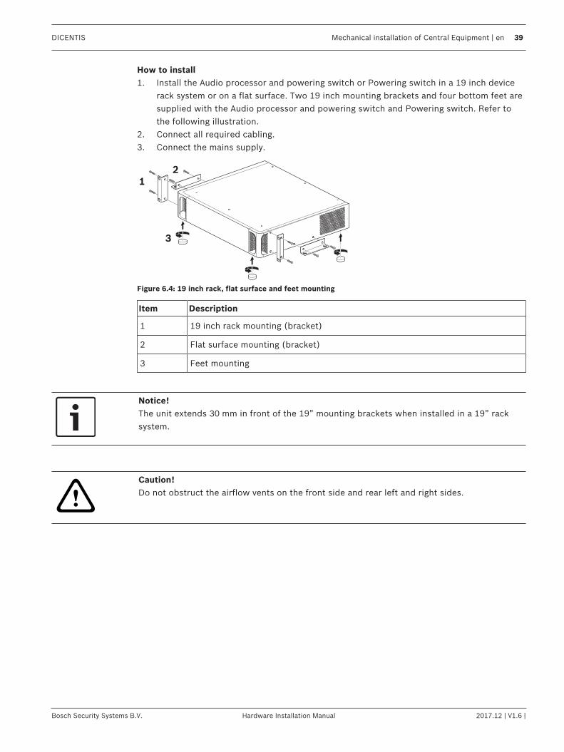
How to install1. Install the Audio processor and powering switch or Powering switch in a 19 inch device
rack system or on a flat surface. Two 19 inch mounting brackets and four bottom feet aresupplied with the Audio processor and powering switch and Powering switch. Refer tothe following illustration.
2. Connect all required cabling.3. Connect the mains supply.
1
2
3
Figure 6.4: 19 inch rack, flat surface and feet mounting
Item Description
1 19 inch rack mounting (bracket)
2 Flat surface mounting (bracket)
3 Feet mounting
Notice!The unit extends 30 mm in front of the 19” mounting brackets when installed in a 19” racksystem.
!
Caution!Do not obstruct the airflow vents on the front side and rear left and right sides.

40 en | Mechanical installation of Contribution Devices DICENTIS
2017.12 | V1.6 | Hardware Installation Manual Bosch Security Systems B.V.
7 Mechanical installation of Contribution Devices7.1 DICENTIS devices
The DICENTIS devices (DCNM-D, DCNM-DVT, DCNM-DSL, DCNM-DE, DCNM-MMD, DCNM-MMD2) are used to:– participate in a meeting or conference.– monitor and control a meeting or conference (chairperson use, depending on the
configuration).
DCNM-MMD / DCNM-MMD2
1
4
5
78 6
9
10
32
Figure 7.1: Front, top, rear and side views
Item Description
1 7” capacitive touch screen.
2 LED strip.
3 Two‑way loudspeaker.
4 3.5 mm stereo jack for headphone or headset with integrated microphone.
5 Headphone volume control.
6 Microphone request button.
7 Chairperson priority or microphone mute button.
8 Near Field Communication (NFC) reader (DCNM-MMD2 only).
9 Cable guides.
10 Microphone input connector.
– DCNM-MMD2 is compliant with the Radio Equipment Directive (RED) 2014/53/EU.– Operating frequency is 13.56 MHz. Maximum field strength is 8.05 dBµA/m @ 3m.
!
Warning!This equipment is compliant with Class A of CISPR 32. In a residential environment thisequipment may cause radio interference. This equipment is intended for environment Class A.
DICENTIS Mechanical installation of Contribution Devices | en 41
Bosch Security Systems B.V. Hardware Installation Manual 2017.12 | V1.6 |
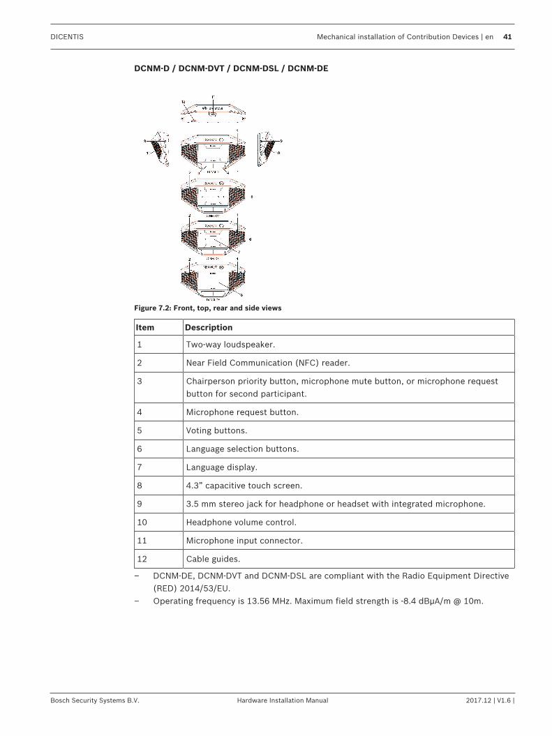
DCNM-D / DCNM-DVT / DCNM-DSL / DCNM-DE
Figure 7.2: Front, top, rear and side views
Item Description
1 Two‑way loudspeaker.
2 Near Field Communication (NFC) reader.
3 Chairperson priority button, microphone mute button, or microphone requestbutton for second participant.
4 Microphone request button.
5 Voting buttons.
6 Language selection buttons.
7 Language display.
8 4.3” capacitive touch screen.
9 3.5 mm stereo jack for headphone or headset with integrated microphone.
10 Headphone volume control.
11 Microphone input connector.
12 Cable guides.
– DCNM-DE, DCNM-DVT and DCNM-DSL are compliant with the Radio Equipment Directive(RED) 2014/53/EU.
– Operating frequency is 13.56 MHz. Maximum field strength is -8.4 dBµA/m @ 10m.
42 en | Mechanical installation of Contribution Devices DICENTIS
2017.12 | V1.6 | Hardware Installation Manual Bosch Security Systems B.V.
Connecting DICENTIS devicesThe DICENTIS Conference System can be quickly and easily configured as a daisy‑chainconfiguration or as a star configuration:– Daisy‑chain configuration: Uses dedicated cabling, consisting of CAT‑5e cables including
two additional power conductors (see Typical system setup, page 8).– Star configuration: Each DICENTIS device is connected with an individual standard
CAT‑5e cable. An Ethernet switch is also required for providing Power over Ethernet(PoE).
Notice!When Power over Ethernet is used, DICENTIS devices cannot be daisy‑chained. Please useunshielded cable for the DICENTIS discussion devices.
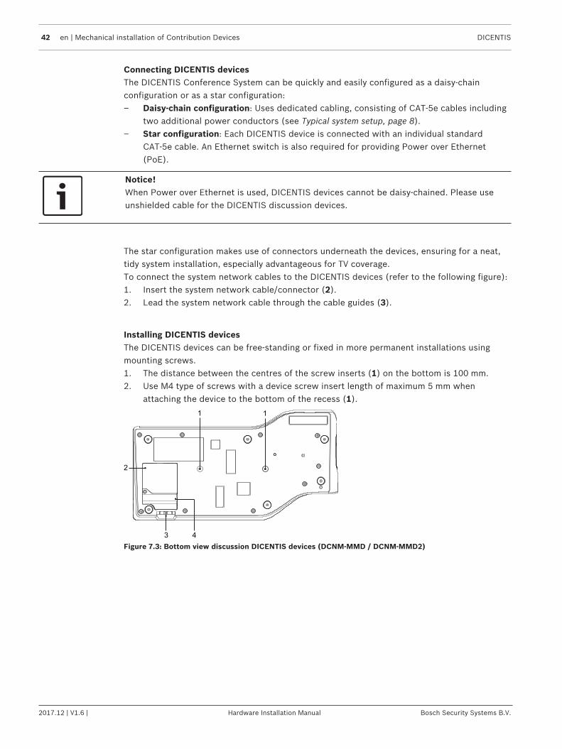
The star configuration makes use of connectors underneath the devices, ensuring for a neat,tidy system installation, especially advantageous for TV coverage.To connect the system network cables to the DICENTIS devices (refer to the following figure):1. Insert the system network cable/connector (2).2. Lead the system network cable through the cable guides (3).
Installing DICENTIS devicesThe DICENTIS devices can be free-standing or fixed in more permanent installations usingmounting screws.1. The distance between the centres of the screw inserts (1) on the bottom is 100 mm.2. Use M4 type of screws with a device screw insert length of maximum 5 mm when
attaching the device to the bottom of the recess (1).
3 4
1 1
2
Figure 7.3: Bottom view discussion DICENTIS devices (DCNM-MMD / DCNM-MMD2)

DICENTIS Mechanical installation of Contribution Devices | en 43
Bosch Security Systems B.V. Hardware Installation Manual 2017.12 | V1.6 |
1 1
3 2
Figure 7.4: Bottom view DICENTIS devices (DCNM-D / DCNM-DVT / DCNM-DSL / DCNM-DE)
Item Description
1 Screw insert for fixed installation.
2 2x RJ45 connection input/output for system power cable.
3 Cable guides.
4 USB connector, for future use (DCNM-MMD / DCNM-MMD2 only).
See also– DICENTIS System Cable Assemblies, page 26– DCNM-CB250-I System Installation Cable, page 30
44 en | Mechanical installation of Contribution Devices DICENTIS
2017.12 | V1.6 | Hardware Installation Manual Bosch Security Systems B.V.
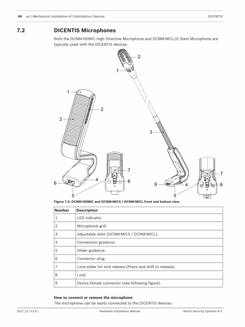
7.2 DICENTIS MicrophonesBoth the DCNM‑HDMIC High Directive Microphone and DCNM-MICL/S Stem Microphone aretypically used with the DICENTIS devices.
3
6 4
7
1
2
5
8
2
64
7
1
2
5
8
Figure 7.5: DCNM‑HDMIC and DCNM‑MICS / DCNM‑MICL front and bottom view
Number Description
1 LED indicator.
2 Microphone grill.
3 Adjustable stem (DCNM‑MICS / DCNM‑MICL).
4 Connection guidance.
5 Slider guidance.
6 Connector plug.
7 Lock-slider for lock release (Press and shift to release).
8 Lock.
9 Device female connector (see following figure).
How to connect or remove the microphoneThe microphone can be easily connected to the DICENTIS devices:
DICENTIS Mechanical installation of Contribution Devices | en 45
Bosch Security Systems B.V. Hardware Installation Manual 2017.12 | V1.6 |
9
6 4
857
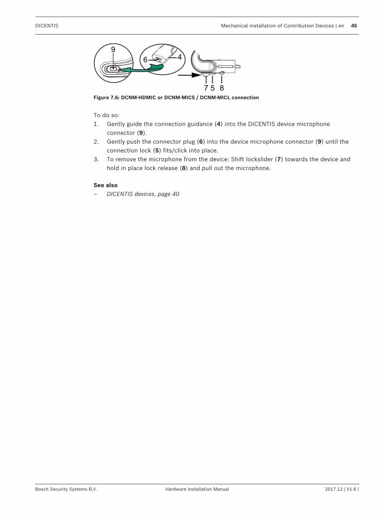
Figure 7.6: DCNM‑HDMIC or DCNM-MICS / DCNM-MICL connection
To do so:1. Gently guide the connection guidance (4) into the DICENTIS device microphone
connector (9).2. Gently push the connector plug (6) into the device microphone connector (9) until the
connection lock (5) fits/click into place.3. To remove the microphone from the device: Shift lockslider (7) towards the device and
hold in place lock release (8) and pull out the microphone.
See also– DICENTIS devices, page 40
46 en | Mechanical installation of Contribution Devices DICENTIS
2017.12 | V1.6 | Hardware Installation Manual Bosch Security Systems B.V.
7.3 DCNM-MMDSP Anti-reflection foilThe DICENTIS anti‑reflection foil can be used to protect the tempered glass screen of aDICENTIS multimedia Device.
Installation procedure1. Use the included alcohol swab and the microfiber fabric to clean the device LCD screen
before installation.2. Peel the positioning adhesive release paper from the rear of anti‑reflection foil.3. Position the anti‑reflection foil on the device LCD screen, and then fix the positioning
adhesive to the side of the device.4. Open the anti‑reflection foil, and use the “cleaning stick” to clean surface dust from the
LCD screen.5. Peel the protective film from the other side of the anti‑reflection foil.6. Lightly press the anti‑reflection foil on to the LCD screen. If air bubbles are trapped under
the anti‑reflection foil, use the “squeegee” to remove them.
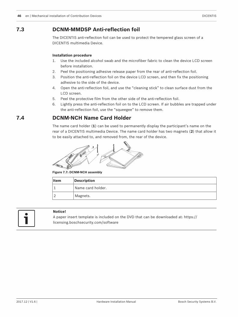
7.4 DCNM-NCH Name Card HolderThe name card holder (1) can be used to permanently display the participant’s name on therear of a DICENTIS multimedia Device. The name card holder has two magnets (2) that allow itto be easily attached to, and removed from, the rear of the device.
1 2
2
Figure 7.7: DCNM‑NCH assembly
Item Description
1 Name card holder.
2 Magnets.
Notice!A paper insert template is included on the DVD that can be downloaded at: https://licensing.boschsecurity.com/software

DICENTIS Installation Test | en 47
Bosch Security Systems B.V. Hardware Installation Manual 2017.12 | V1.6 |
8 Installation TestAn installation test is needed to prevent connection mismatches and find potential productdefects at an early stage. Not to do so could result in a system malfunctioning.Each DICENTIS device has its own built‑in diagnostics, which can be used for faultfinding. Thediagnostics starts as soon the DICENTIS device is powered on. The DICENTIS ConferenceSystem does not have to be configured with, and connected to, the system controller PC.
Preconditions1. All system network cables are connected to the devices.2. The Audio processor and powering switch and Powering switch(es) are installed.
Start the testPower on the Audio processor and powering switches and Powering switches used in thesystem: Each connected device powers on and initializes.
1. After the DICENTIS multimedia Device / the DICENTIS discussion Extended haveinitialized, the diagnostic screen is shown.
2. If the text “Link down” is shown:– The network cable is not connected or defective.– The device is only connected with one system network cable (“Link down” is shown
on the side where the device is not connected).3. If the system network cable is correctly connected to the network, the network speed is
shown.4. If the DICENTIS multimedia Device / the DICENTIS discussion Extended are connected to
an Audio processor and powering switch, Powering switch or another multimedia device,and 100 Mb is shown:– Not all wiring inside the system network cable connector is correctly connected or
broken. You need to check the wiring and connector.– If the cable is connected to a 100 Mb switch, it is correct.
5. Click the info button to see additional information of the multimedia device.6. When everything is correctly connected, and the device does not have the application
software, it shows the text “Please download software”.7. Now the device can be downloaded:

48 en | Installation Test DICENTIS
2017.12 | V1.6 | Hardware Installation Manual Bosch Security Systems B.V.
– Downloading devices is not covered in this manual. Refer to the DICENTISconfiguration manual on how to download the devices.
Customer serviceIf a fault cannot be resolved, please contact your supplier or system integrator, or go directlyto your Bosch representative.

Bosch Security Systems B.V.Torenallee 495617 BA EindhovenNetherlandswww.boschsecurity.com© Bosch Security Systems B.V., 2018


