Hardware Manual 9800 Operator Interface Terminal Quartech Corporation 15923 Angelo Drive Macomb Township, Michigan 48042-4050 Phone: (586) 781-0373 FAX: (586) 781-0378 www.QuartechCorp.com HM9800 Revision 10 The product described in this document can have a variety of uses, the user and those responsible for applying this equipment must satisfy themselves as to the acceptability of each application and the use of the unit. Under no circumstances will QUARTECH CORPORATION be responsible or liable for any damage, including indirect or consequential losses resulting from the use, misuse, or application of the unit. The text, illustrations, charts, and examples included in this document are intended solely to help explain applications of the product. Due to the many variables associated with specific uses or applications, QUARTECH CORPORATION cannot assume responsibility or liability for actual use based upon the data provided in this document. No patent liability is assumed by QUARTECH CORPORATION with respect to the use of circuits, information, equipment, or software described in this document. This document is subject to change without notice.
The product described in this document can have a variety of uses, the user and those responsible for applying thisequipment must satisfy themselves as to the acceptability of each application and the use of the unit. Under nocircumstances will QUARTECH CORPORATION be responsible or liable for any damage, including indirect orconsequential losses resulting from the use, misuse, or application of the unit.
The text, illustrations, charts, and examples included in this document are intended solely to help explain applicationsof the product. Due to the many variables associated with specific uses or applications, QUARTECH CORPORATIONcannot assume responsibility or liability for actual use based upon the data provided in this document.
No patent liability is assumed by QUARTECH CORPORATION with respect to the use of circuits, information,equipment, or software described in this document.
This document is subject to change without notice.
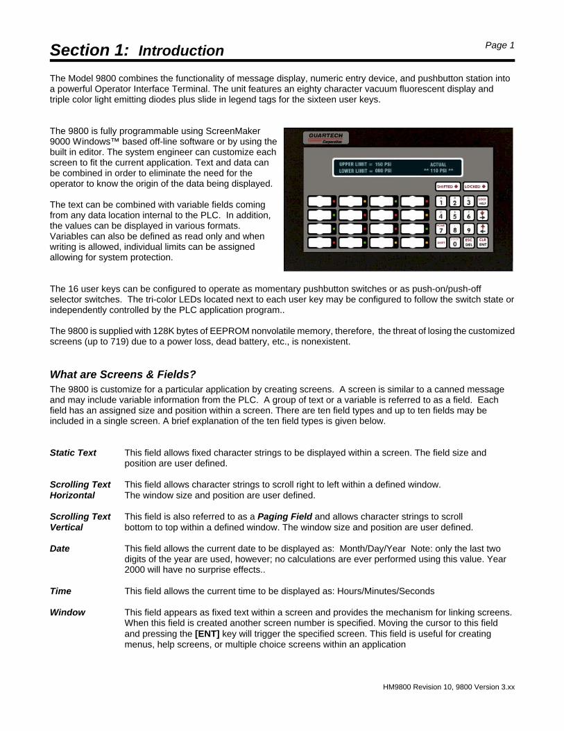
The Model 9800 combines the functionality of message display, numeric entry device, and pushbutton station intoa powerful Operator Interface Terminal. The unit features an eighty character vacuum fluorescent display andtriple color light emitting diodes plus slide in legend tags for the sixteen user keys.
The 9800 is fully programmable using ScreenMaker9000 Windows™ based off-line software or by using thebuilt in editor. The system engineer can customize eachscreen to fit the current application. Text and data canbe combined in order to eliminate the need for theoperator to know the origin of the data being displayed.
The text can be combined with variable fields comingfrom any data location internal to the PLC. In addition,the values can be displayed in various formats.Variables can also be defined as read only and whenwriting is allowed, individual limits can be assignedallowing for system protection.
The 16 user keys can be configured to operate as momentary pushbutton switches or as push-on/push-offselector switches. The tri-color LEDs located next to each user key may be configured to follow the switch state orindependently controlled by the PLC application program..
The 9800 is supplied with 128K bytes of EEPROM nonvolatile memory, therefore, the threat of losing the customizedscreens (up to 719) due to a power loss, dead battery, etc., is nonexistent.
What are Screens & Fields?The 9800 is customize for a particular application by creating screens. A screen is similar to a canned messageand may include variable information from the PLC. A group of text or a variable is referred to as a field. Eachfield has an assigned size and position within a screen. There are ten field types and up to ten fields may beincluded in a single screen. A brief explanation of the ten field types is given below.
Static Text This field allows fixed character strings to be displayed within a screen. The field size andposition are user defined.
Scrolling Text This field allows character strings to scroll right to left within a defined window.Horizontal The window size and position are user defined.
Scrolling Text This field is also referred to as a Paging Field and allows character strings to scroll Vertical bottom to top within a defined window. The window size and position are user defined.
Date This field allows the current date to be displayed as: Month/Day/Year Note: only the last twodigits of the year are used, however; no calculations are ever performed using this value. Year2000 will have no surprise effects..
Time This field allows the current time to be displayed as: Hours/Minutes/Seconds
Window This field appears as fixed text within a screen and provides the mechanism for linking screens.When this field is created another screen number is specified. Moving the cursor to this fieldand pressing the [ENT] key will trigger the specified screen. This field is useful for creatingmenus, help screens, or multiple choice screens within an application
Section 1: Introduction Page 2
HM9800 Revision 10, 9800 Version 3.xx
Data Set This field appears as fixed text within a screen. When this field is created an address and a datavalue are specified in addition to the field text. Moving the cursor to this field and pressing the[ENT] key will cause the data value to be written to the assigned address within the PLC.
Bit Status When creating this field a data bit and PLC address are specified. Two character strings arealso typed in, one for the off state of the bit and one for the on state of the bit. One of the twocharacter strings will then be displayed depending on the status of the specified data bit. Ifenabled this field will also function as a bit modify. Moving the cursor to the field and pressingthe [ENT] key will cause the bit to be complimented by the 9800.
PLC Data This field will display variable information from within the PLC. The address from which data willbe retrieved is specified when the PLC Data field is created. The data can be displayed in Hex,Octal, Binary, Decimal, or floating point formats. Modification to the value may be enabled ordisabled. Individual data value limits are also set for each PLC Data field created. If enabled,values are entered by first moving the cursor to this field then pressing the [ENT] key; a newvalue is then keyed in and the [ENT] key pressed.
Bar Chart This field is displayed as a conventional bar chart expanding from left to right relative to thevalue of an assigned address within the PLC. During field creation the address is specified, ascale value that is applied to the raw data prior to display, and the character that will be use inthe bar.
Resident Screen EditorA six pin circular mini-DIN connector is located at the bottom of the 9800. A standard IBM compatible AT keyboardcan be connected directly into this connector. This keyboard is then used to configure the 9800 and programscreens. This is possible because the 9800 includes a resident text editor. This editor is menu driven, i.e., theprogrammer is prompted through various screens to select or enter parameters.
The various menus that make up the resident editor are actually screens that are very much like the user screensthat will be created. The resident editor screens utilize five field types, which are: Word Fields, Entry Fields, MenuFields, Task Fields, and Choice Fields. These fields allow the user to enter screen text and make variousparameter assignments.
The fields that make up the editor screens can be separated into two categories, information fields and actionfields. A Word Field is an information field. It is made of characters that will never move, flash, or change. If aneditor screen includes an action field it will flash when the cursor is on it to indicate some action is possible. Thisaction includes the entering of data, multiple choice selection, selection of another menu, or initiation of a tasksuch as printing or deleting. If more than one action field is present the arrow keys are used to move betweenthem.
The following is a description of the action fields used in the resident editor:
Entry Field To initiate action within this field the [Enter] key is pressed. If the field allows data entry a blockcursor "œ" will appear in the left most entry position. The original data will remain but will stopflashing. This is typeover entry mode. Data can be keyed in then, the [Enter] key pressed tocomplete the operation.
If [Shift] [Enter] is used to select the field the block cursor will appear, however, the original datawill disappear. This is new entry mode. As before, data can be keyed in then the [Enter] keypressed to complete the operation.
Section 1: Introduction Page 3
HM9800 Revision 10, 9800 Version 3.xx
Operator Interface for AB PLC-59800-VV-WW-3-Z V3.XX SN. 123456
Edit screen Setup System Run Mode
Utilities
Menu Field To initiate action in this field the [Enter] key is pressed which will produce a new screen.
Task Field To initiate action in this field the [Enter] key is pressed which will cause a predefined task to beperformed. These tasks include printing, deleting, and saving data. In some cases a word such as"BUSY", "SAVING", "DELETING", or "ONLINE" will appear at the top right position on the displayindicating the task is being performed.
Choice Field The [Enter] key is used to scroll through the available choices. Screens that utilize this type of fieldoften include a Task Field labeled "Save setup". Before leaving these screens the "Save setup"task must be executed to save any changes that were made.
It is important to understand what these fields are and how data is modified in each one since it will be assumedthis is known information throughout the rest of this manual. As a general rule the [Enter] key allows access intoand out of a field. The [Esc] key will back out of or discontinue an operation.
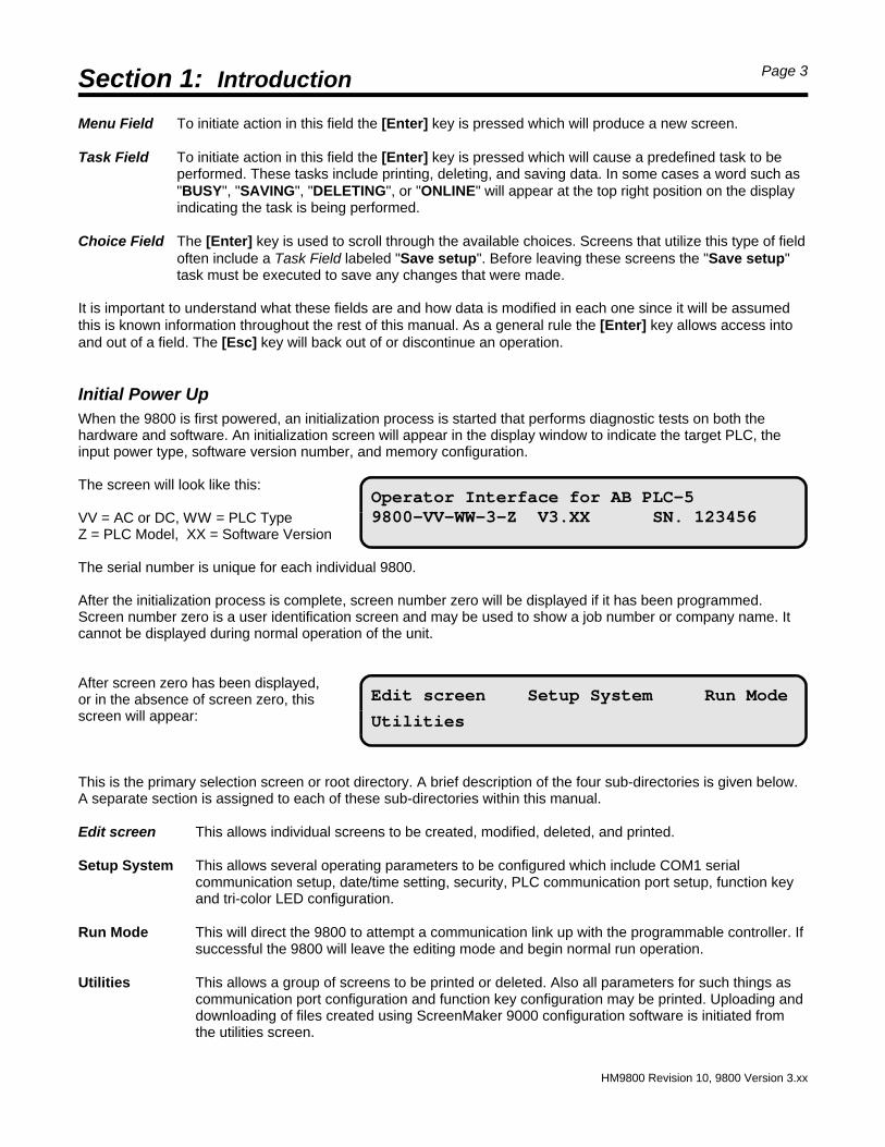
Initial Power UpWhen the 9800 is first powered, an initialization process is started that performs diagnostic tests on both thehardware and software. An initialization screen will appear in the display window to indicate the target PLC, theinput power type, software version number, and memory configuration.
The screen will look like this:
VV = AC or DC, WW = PLC TypeZ = PLC Model, XX = Software Version
The serial number is unique for each individual 9800.
After the initialization process is complete, screen number zero will be displayed if it has been programmed.Screen number zero is a user identification screen and may be used to show a job number or company name. Itcannot be displayed during normal operation of the unit.
After screen zero has been displayed,or in the absence of screen zero, this screen will appear:
This is the primary selection screen or root directory. A brief description of the four sub-directories is given below.A separate section is assigned to each of these sub-directories within this manual.
Edit screen This allows individual screens to be created, modified, deleted, and printed.
Setup System This allows several operating parameters to be configured which include COM1 serialcommunication setup, date/time setting, security, PLC communication port setup, function keyand tri-color LED configuration.
Run Mode This will direct the 9800 to attempt a communication link up with the programmable controller. Ifsuccessful the 9800 will leave the editing mode and begin normal run operation.
Utilities This allows a group of screens to be printed or deleted. Also all parameters for such things ascommunication port configuration and function key configuration may be printed. Uploading anddownloading of files created using ScreenMaker 9000 configuration software is initiated fromthe utilities screen.
Section 2: Edit Mode Page 4
HM9800 Revision 10, 9800 Version 3.xx
Edit screen number:000
Edit Print Delete
Edit screen number:015
Screen does not exist! Create? No Yes
Selecting the Edit Screen field from theroot directory will cause the followingscreen to be displayed:
This screen will be used more often than any other. It allows a new screen to be created or an existing screen tobe modified. This screen also allows a single screen to be printed or deleted. When multiple screens are to beprinted or deleted the Utilities feature from the root directory is used.
The Edit screen number will be flashing to indicate the current cursor position. Prior to selecting any of the threefunctions on the second line a screen number must be entered. The legal address range is zero through 719. Ifthe number that is flashing is the screen of choice it will not be necessary to re-enter it.
The first time the edit screen function is selected the screen number appearing will be "000". For example purposeassume screen number 15 is to be created. The first step is to enter the number fifteen as the "Edit screennumber:" parameter. Press [1] [5] [Enter]. Next move the cursor to "Edit" by pressing the [!!] key. The word"Edit" will begin to flash indicating the cursor is at that position. Select the "Edit" function by pressing the [Enter]key. The word "BUSY" will appear at the top right of the display for a moment, then assuming this screen has notbeen previously created the following screen will display:
The word "No" will be flashing. To select "Yes" press the [!!] key followed by the [Enter] key. The screen willblank except for a block cursor "œ" at the top left position of the display. This is the cursor home position. Pressingthe [Home] key will always return the cursor to this position. Pressing the [End] key will in some cases move thecursor to the bottom right position of the display.
Editor Function Key AssignmentsFunction keys [F1] through [F10] on the computer AT keyboard are used to create and modify screens.
[F1] Flash: This key will toggle the flashing attribute flag of the field in which the cursor currently resides. Thisflag determines if the field characters will flash when the screen is displayed.
[F2] Edit Screen Flags: This key produces another screen which allows several screen related attribute flagsto be modified. This setup must be completed for each screen that does not utilize the default attributes.The various flags will be discussed in detail later in this section.
[F3] Edit Text: This key allows re-entry into a previously created field for the purpose of editing. This key isonly active when the cursor is placed on an existing field.
[F4] Edit Field Parameters: This key will display a setup screen unique to the field type the cursor is currentlyon. This key is only active when the cursor is placed on a field that has modifiable parameters.
[F5] Move Field: To reposition a field the cursor must first be moved to that field. [F5] is then pressed whichwill cause the entire field to become blocks. The arrow keys are used to reposition; the [Enter] key isused to complete the move.
[F6] Resize Field: To re-size a field the cursor must first be moved to that field. [F6] is then pressed whichwill cause a flashing block cursor to appear over the entire field. The arrow keys are used to increase ordecrease the field size. The [Enter] key is used to complete the re-sizing.
Section 2: Edit Mode Page 5
HM9800 Revision 10, 9800 Version 3.xx
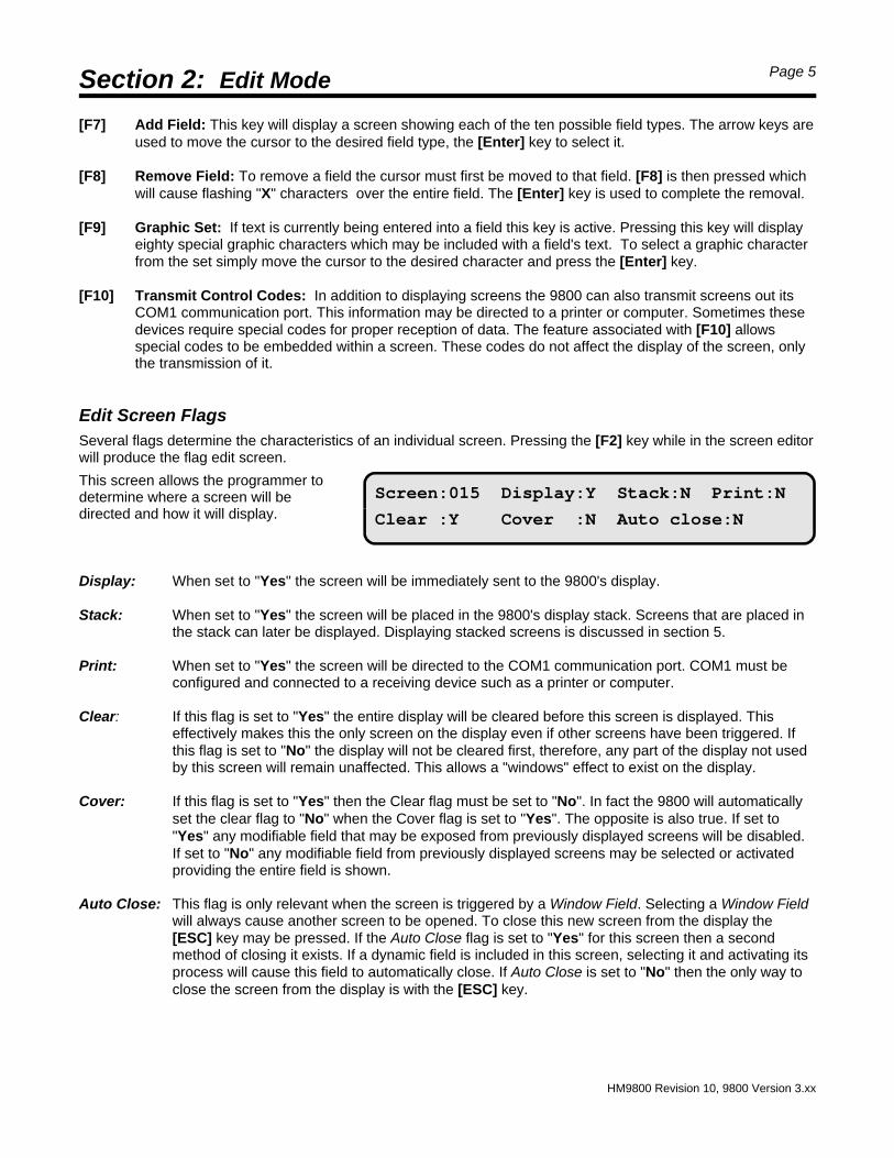
Screen:015 Display:Y Stack:N Print:N
Clear :Y Cover :N Auto close:N
[F7] Add Field: This key will display a screen showing each of the ten possible field types. The arrow keys areused to move the cursor to the desired field type, the [Enter] key to select it.
[F8] Remove Field: To remove a field the cursor must first be moved to that field. [F8] is then pressed whichwill cause flashing "X" characters over the entire field. The [Enter] key is used to complete the removal.
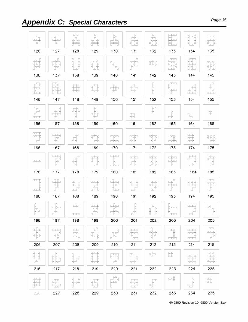
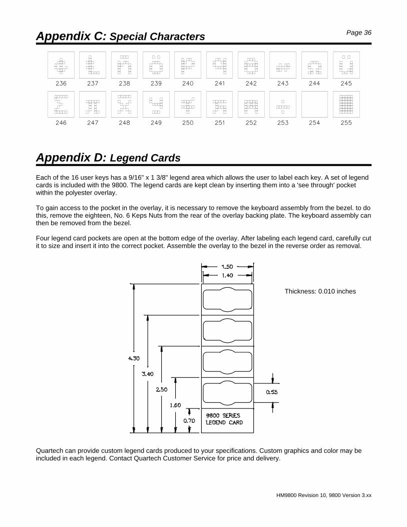
[F9] Graphic Set: If text is currently being entered into a field this key is active. Pressing this key will displayeighty special graphic characters which may be included with a field's text. To select a graphic characterfrom the set simply move the cursor to the desired character and press the [Enter] key.
[F10] Transmit Control Codes: In addition to displaying screens the 9800 can also transmit screens out itsCOM1 communication port. This information may be directed to a printer or computer. Sometimes thesedevices require special codes for proper reception of data. The feature associated with [F10] allowsspecial codes to be embedded within a screen. These codes do not affect the display of the screen, onlythe transmission of it.
Edit Screen FlagsSeveral flags determine the characteristics of an individual screen. Pressing the [F2] key while in the screen editorwill produce the flag edit screen.
This screen allows the programmer todetermine where a screen will bedirected and how it will display.
Display: When set to "Yes" the screen will be immediately sent to the 9800's display.
Stack: When set to "Yes" the screen will be placed in the 9800's display stack. Screens that are placed inthe stack can later be displayed. Displaying stacked screens is discussed in section 5.
Print: When set to "Yes" the screen will be directed to the COM1 communication port. COM1 must beconfigured and connected to a receiving device such as a printer or computer.
Clear: If this flag is set to "Yes" the entire display will be cleared before this screen is displayed. Thiseffectively makes this the only screen on the display even if other screens have been triggered. Ifthis flag is set to "No" the display will not be cleared first, therefore, any part of the display not usedby this screen will remain unaffected. This allows a "windows" effect to exist on the display.
Cover: If this flag is set to "Yes" then the Clear flag must be set to "No". In fact the 9800 will automaticallyset the clear flag to "No" when the Cover flag is set to "Yes". The opposite is also true. If set to"Yes" any modifiable field that may be exposed from previously displayed screens will be disabled.If set to "No" any modifiable field from previously displayed screens may be selected or activatedproviding the entire field is shown.
Auto Close: This flag is only relevant when the screen is triggered by a Window Field. Selecting a Window Fieldwill always cause another screen to be opened. To close this new screen from the display the[ESC] key may be pressed. If the Auto Close flag is set to "Yes" for this screen then a secondmethod of closing it exists. If a dynamic field is included in this screen, selecting it and activating itsprocess will cause this field to automatically close. If Auto Close is set to "No" then the only way toclose the screen from the display is with the [ESC] key.
Section 2: Edit Mode Page 6
HM9800 Revision 10, 9800 Version 3.xx
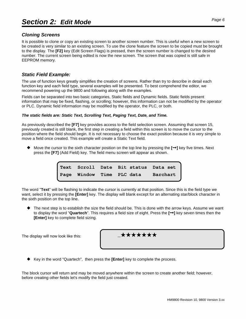
Text Scroll Date Bit status Data set
Page Window Time PLC data Barchart
_ÚÚÚÚÚÚÚÚÚÚÚÚÚÚ
Cloning ScreensIt is possible to clone or copy an existing screen to another screen number. This is useful when a new screen tobe created is very similar to an existing screen. To use the clone feature the screen to be copied must be broughtto the display. The [F2] key (Edit Screen Flags) is pressed, then the screen number is changed to the desirednumber. The current screen being edited is now the new screen. The screen that was copied is still safe inEEPROM memory.
Static Field Example:The use of function keys greatly simplifies the creation of screens. Rather than try to describe in detail eachfunction key and each field type, several examples will be presented. To best comprehend the editor, werecommend powering up the 9800 and following along with the examples.
Fields can be separated into two basic categories, Static fields and Dynamic fields. Static fields presentinformation that may be fixed, flashing, or scrolling; however, this information can not be modified by the operatoror PLC. Dynamic field information may be modified by the operator, the PLC, or both.
The static fields are: Static Text, Scrolling Text, Paging Text, Date, and Time.
As previously described the [F7] key provides access to the field selection screen. Assuming that screen 15,previously created is still blank, the first step in creating a field within this screen is to move the cursor to theposition where the field should begin. It is not necessary to choose the exact position because it is very simple tomove a field once created. This example will create a Static Text field.
— Move the cursor to the sixth character position on the top line by pressing the [!!] key five times. Nextpress the [F7] (Add Field) key. The field menu screen will appear as shown.
The word "Text" will be flashing to indicate the cursor is currently at that position. Since this is the field type wewant, select it by pressing the [Enter] key. The display will blank except for an alternating star/block character inthe sixth position on the top line.
— The next step is to establish the size the field should be. This is done with the arrow keys. Assume we wantto display the word "Quartech". This requires a field size of eight. Press the [!!] key seven times then the[Enter] key to complete field sizing.
The display will now look like this:
— Key in the word "Quartech", then press the [Enter] key to complete the process.
The block cursor will return and may be moved anywhere within the screen to create another field; however,before creating other fields let's modify the field just created.
Section 2: Edit Mode Page 7
HM9800 Revision 10, 9800 Version 3.xx
Edit screen number:015
Save screen changes before exit? Yes No
— Use the arrow keys to position the cursor somewhere within the "Quartech" field then press the [F6](Resize Field) key. Press the [!!] key five times to increase the field size by five characters. Notice that thestar character "ÚÚ" is used to indicate reserved but unused character positions. Press the [Enter] key tocomplete re-sizing. The stars disappear leaving only the word "Quartech".
Append the text field to read "Quartech 9800"
— Press the [F3] (Edit Text) key. The stars will again appear in the reserved character positions. Also, aflashing underline cursor will appear.
Before proceeding press the [Insert] key. Notice the flashing underline cursor changes to a flashing block cursor.The block cursor indicates the text editor is in typeover mode. The underline cursor indicates the text editor is ininsert mode. To append text to an existing field either mode will work.
— Use the arrow keys to position the cursor immediately to the right of the "h". Press the space bar then [9][8] [0] [0] [Enter]. The modification is complete and the field will read "Quartech 9800".
Move the field.
— With the cursor somewhere within the text field press the [F5] key. The field will fill with non-flashing blocks.The field may be moved using the arrow keys, [Home] key, or [End] key. When the field appears in thedesired position press the [Enter] key to complete the move.
Add flashing.
— Any field can be made to flash. Move the cursor into the text field then press the [F1] key. The field willbegin to flash. Press the [F1] key again and notice the flashing stops. The [F1] key toggles a field attributeflag that will enable or disable flashing.
Saving the screen in memory.
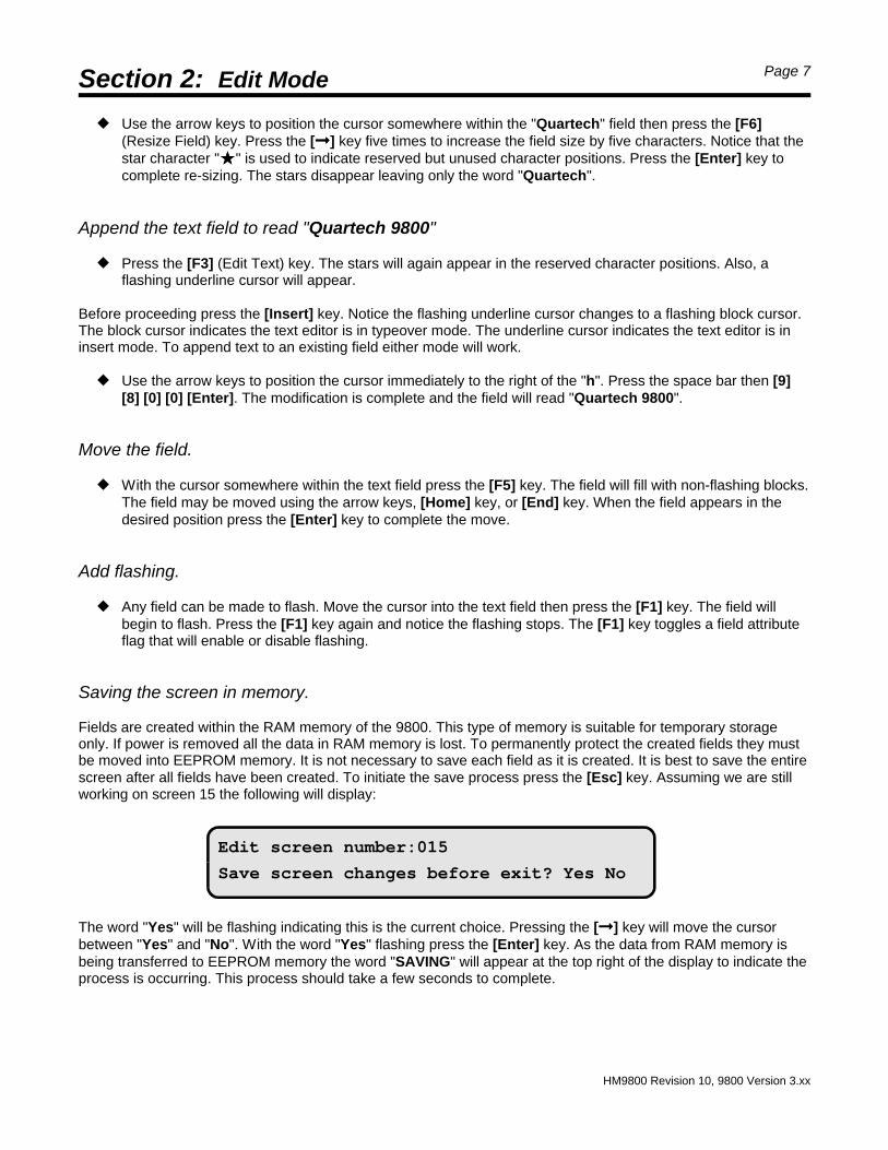
Fields are created within the RAM memory of the 9800. This type of memory is suitable for temporary storageonly. If power is removed all the data in RAM memory is lost. To permanently protect the created fields they mustbe moved into EEPROM memory. It is not necessary to save each field as it is created. It is best to save the entirescreen after all fields have been created. To initiate the save process press the [Esc] key. Assuming we are stillworking on screen 15 the following will display:
The word "Yes" will be flashing indicating this is the current choice. Pressing the [!!] key will move the cursorbetween "Yes" and "No". With the word "Yes" flashing press the [Enter] key. As the data from RAM memory isbeing transferred to EEPROM memory the word "SAVING" will appear at the top right of the display to indicate theprocess is occurring. This process should take a few seconds to complete.
Section 2: Edit Mode Page 8
HM9800 Revision 10, 9800 Version 3.xx
Edit screen number:015
Edit Print Delete
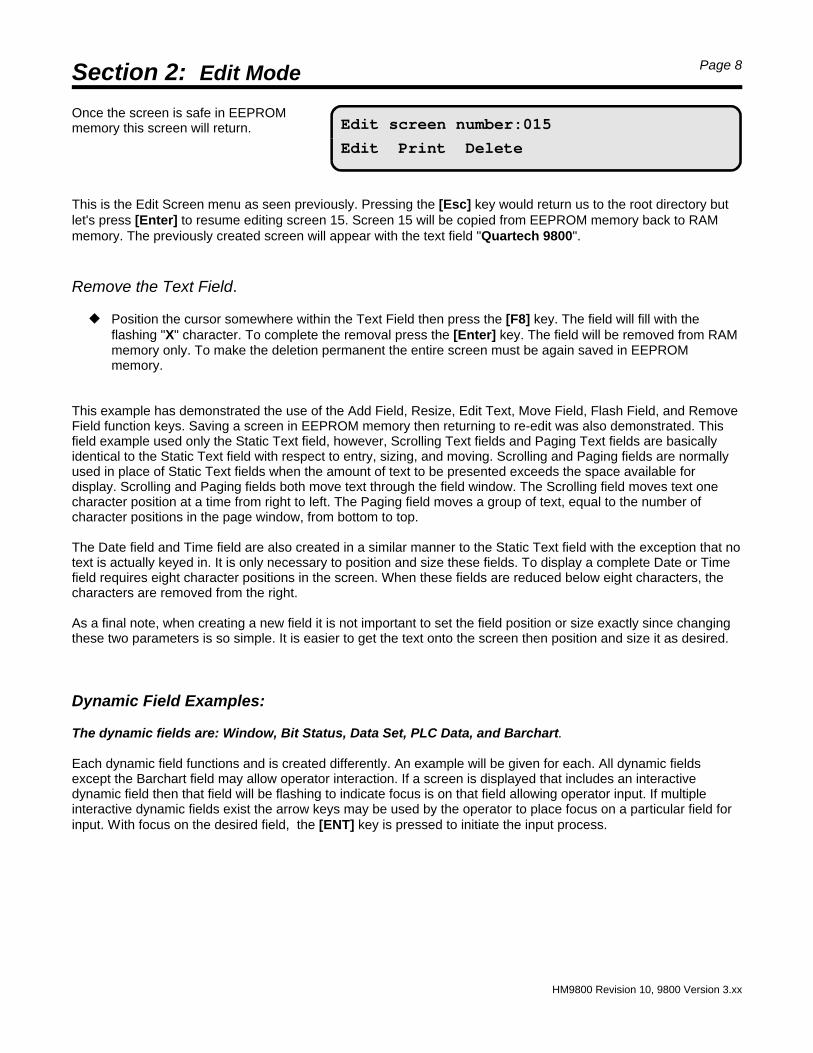
Once the screen is safe in EEPROMmemory this screen will return.
This is the Edit Screen menu as seen previously. Pressing the [Esc] key would return us to the root directory butlet's press [Enter] to resume editing screen 15. Screen 15 will be copied from EEPROM memory back to RAMmemory. The previously created screen will appear with the text field "Quartech 9800".
Remove the Text Field.
— Position the cursor somewhere within the Text Field then press the [F8] key. The field will fill with theflashing "X" character. To complete the removal press the [Enter] key. The field will be removed from RAMmemory only. To make the deletion permanent the entire screen must be again saved in EEPROMmemory.
This example has demonstrated the use of the Add Field, Resize, Edit Text, Move Field, Flash Field, and RemoveField function keys. Saving a screen in EEPROM memory then returning to re-edit was also demonstrated. Thisfield example used only the Static Text field, however, Scrolling Text fields and Paging Text fields are basicallyidentical to the Static Text field with respect to entry, sizing, and moving. Scrolling and Paging fields are normallyused in place of Static Text fields when the amount of text to be presented exceeds the space available fordisplay. Scrolling and Paging fields both move text through the field window. The Scrolling field moves text onecharacter position at a time from right to left. The Paging field moves a group of text, equal to the number ofcharacter positions in the page window, from bottom to top.
The Date field and Time field are also created in a similar manner to the Static Text field with the exception that notext is actually keyed in. It is only necessary to position and size these fields. To display a complete Date or Timefield requires eight character positions in the screen. When these fields are reduced below eight characters, thecharacters are removed from the right.
As a final note, when creating a new field it is not important to set the field position or size exactly since changingthese two parameters is so simple. It is easier to get the text onto the screen then position and size it as desired.
Dynamic Field Examples:
The dynamic fields are: Window, Bit Status, Data Set, PLC Data, and Barchart.
Each dynamic field functions and is created differently. An example will be given for each. All dynamic fieldsexcept the Barchart field may allow operator interaction. If a screen is displayed that includes an interactivedynamic field then that field will be flashing to indicate focus is on that field allowing operator input. If multipleinteractive dynamic fields exist the arrow keys may be used by the operator to place focus on a particular field forinput. With focus on the desired field, the [ENT] key is pressed to initiate the input process.
Section 2: Edit Mode Page 9
HM9800 Revision 10, 9800 Version 3.xx
Entry:Yes Screen:000
Entry:No Msk:0000000000000000
Addrs:XXXXX Val:0000000000000000
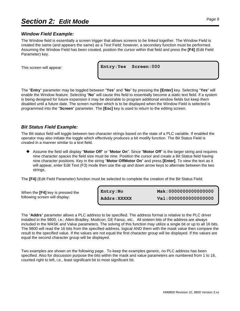
Window Field Example:The Window field is essentially a screen trigger that allows screens to be linked together. The Window Field iscreated the same (and appears the same) as a Text Field; however, a secondary function must be performed.Assuming the Window Field has been created, position the cursor within that field and press the [F4] (Edit FieldParameter) key.
This screen will appear:
The "Entry" parameter may be toggled between "Yes" and "No" by pressing the [Enter] key. Selecting "Yes" willenable the Window feature. Selecting "No" will cause this field to essentially become a static text field. If a systemis being designed for future expansion it may be desirable to program additional window fields but keep themdisabled until a future date. The screen number which is to be displayed when the Window Field is selected isprogrammed into the "Screen" parameter. The [Esc] key is used to return to the editing screen.
Bit Status Field Example:The Bit status field will toggle between two character strings based on the state of a PLC variable. If enabled theoperator may also initiate the toggle which effectively produces a bit modify function. The Bit Status Field iscreated in a manner similar to a text field.
— Assume the field will display "Motor Off" or "Motor On". Since "Motor Off" is the larger string and requiresnine character spaces the field size must be nine. Position the cursor and create a Bit Status field havingnine character positions. Key in the string "Motor OffMotor On" and press [Enter]. To view the text as itwill appear, enter Edit Text (F3) mode then use the up and down arrow keys to alternate between the twostrings.
The [F4] (Edit Field Parameter) function must be selected to complete the creation of the Bit Status Field.
When the [F4] key is pressed thefollowing screen will display:
The "Addrs" parameter allows a PLC address to be specified. The address format is relative to the PLC driverinstalled in the 9800, i.e.; Allen-Bradley, Modicon, GE Fanuc, etc.. All sixteen bits of the address are alwaysincluded in the MASK and Value parameters. The solving of this function may utilize a single bit or up to all 16 bits.The 9800 will read the 16 bits from the specified address, logical AND them with the mask value then compare theresult to the specified value. If the values are not equal the first character group will be displayed. If the values areequal the second character group will be displayed.
Two examples are shown on the following page. To keep the examples generic, no PLC address has beenspecified. Also for discussion purpose the bits within the mask and value parameters are numbered from 1 to 16,counted right to left, i.e., least significant bit to most significant bit.
Section 2: Edit Mode Page 10
HM9800 Revision 10, 9800 Version 3.xx
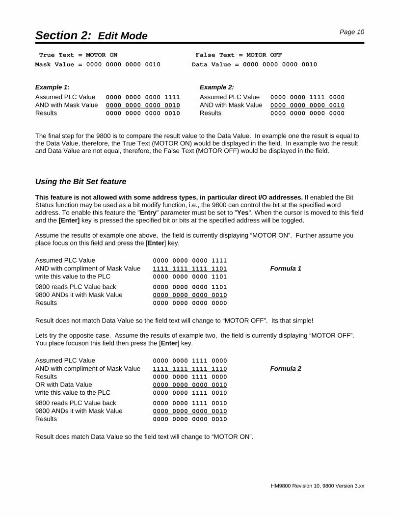
True Text = MOTOR ON False Text = MOTOR OFF
Mask Value = 0000 0000 0000 0010 Data Value = 0000 0000 0000 0010
Example 1: Example 2:
Assumed PLC Value 0000 0000 0000 1111 Assumed PLC Value 0000 0000 1111 0000AND with Mask Value 0000 0000 0000 0010 AND with Mask Value 0000 0000 0000 0010Results 0000 0000 0000 0010 Results 0000 0000 0000 0000
The final step for the 9800 is to compare the result value to the Data Value. In example one the result is equal tothe Data Value, therefore, the True Text (MOTOR ON) would be displayed in the field. In example two the resultand Data Value are not equal, therefore, the False Text (MOTOR OFF) would be displayed in the field.
Using the Bit Set feature
This feature is not allowed with some address types, in particular direct I/O addresses. If enabled the BitStatus function may be used as a bit modify function, i.e., the 9800 can control the bit at the specified wordaddress. To enable this feature the "Entry" parameter must be set to "Yes". When the cursor is moved to this fieldand the [Enter] key is pressed the specified bit or bits at the specified address will be toggled.
Assume the results of example one above, the field is currently displaying “MOTOR ON”. Further assume youplace focus on this field and press the [Enter] key.
Assumed PLC Value 0000 0000 0000 1111AND with compliment of Mask Value 1111 1111 1111 1101 Formula 1write this value to the PLC 0000 0000 0000 1101
9800 reads PLC Value back 0000 0000 0000 11019800 ANDs it with Mask Value 0000 0000 0000 0010Results 0000 0000 0000 0000
Result does not match Data Value so the field text will change to “MOTOR OFF”. Its that simple!
Lets try the opposite case. Assume the results of example two, the field is currently displaying “MOTOR OFF”. You place focuson this field then press the [Enter] key.
Assumed PLC Value 0000 0000 1111 0000AND with compliment of Mask Value 1111 1111 1111 1110 Formula 2Results 0000 0000 1111 0000OR with Data Value 0000 0000 0000 0010write this value to the PLC 0000 0000 1111 0010
9800 reads PLC Value back 0000 0000 1111 00109800 ANDs it with Mask Value 0000 0000 0000 0010Results 0000 0000 0000 0010
Result does match Data Value so the field text will change to “MOTOR ON”.
Section 2: Edit Mode Page 11
HM9800 Revision 10, 9800 Version 3.xx
Entry:No Format:HEX Hi :0000
Addrs:XXXXX Low:0000
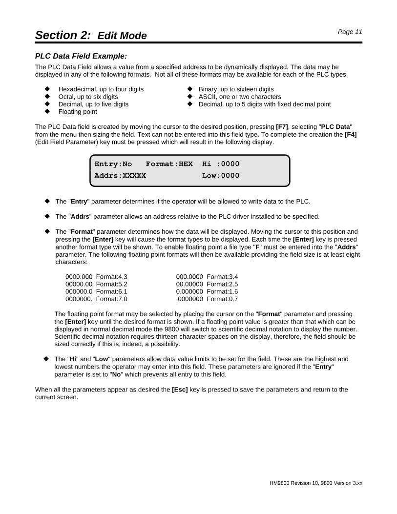
PLC Data Field Example:The PLC Data Field allows a value from a specified address to be dynamically displayed. The data may bedisplayed in any of the following formats. Not all of these formats may be available for each of the PLC types.
— Hexadecimal, up to four digits — Binary, up to sixteen digits— Octal, up to six digits — ASCII, one or two characters— Decimal, up to five digits — Decimal, up to 5 digits with fixed decimal point— Floating point
The PLC Data field is created by moving the cursor to the desired position, pressing [F7], selecting "PLC Data"from the menu then sizing the field. Text can not be entered into this field type. To complete the creation the [F4](Edit Field Parameter) key must be pressed which will result in the following display.
— The "Entry" parameter determines if the operator will be allowed to write data to the PLC.
— The "Addrs" parameter allows an address relative to the PLC driver installed to be specified.
— The "Format" parameter determines how the data will be displayed. Moving the cursor to this position andpressing the [Enter] key will cause the format types to be displayed. Each time the [Enter] key is pressedanother format type will be shown. To enable floating point a file type "F" must be entered into the "Addrs"parameter. The following floating point formats will then be available providing the field size is at least eightcharacters:
The floating point format may be selected by placing the cursor on the "Format" parameter and pressingthe [Enter] key until the desired format is shown. If a floating point value is greater than that which can bedisplayed in normal decimal mode the 9800 will switch to scientific decimal notation to display the number.Scientific decimal notation requires thirteen character spaces on the display, therefore, the field should besized correctly if this is, indeed, a possibility.
— The "Hi" and "Low" parameters allow data value limits to be set for the field. These are the highest andlowest numbers the operator may enter into this field. These parameters are ignored if the "Entry"parameter is set to "No" which prevents all entry to this field.
When all the parameters appear as desired the [Esc] key is pressed to save the parameters and return to thecurrent screen.
Section 2: Edit Mode Page 12
HM9800 Revision 10, 9800 Version 3.xx
Entry:Yes Format:HEX
Addrs:XXXXX Data :0000
Data Set Example:The Data Set field allows a specified value to be written to a specified address within the PLC.
The Data Set field is created by moving the cursor to the desired position, pressing [F7], selecting "Data Set" fromthe menu then sizing the field. The desired text can then be entered into this field . To complete the creation the[F4] (Edit Field Parameter) key must be pressed which will result in the following display.
— The "Entry" parameter determines if the data will be written to the PLC. This parameter would be set to"No" only if the field is being created for use at some future time.
— The "Addrs" parameter allows an address relative to the PLC driver installed to be specified. This is theaddress that the data will be written to.
— The "Format" parameter allows the data value to be expressed several ways. Moving the cursor to thisposition and pressing the [Enter] key will cause the format types below to be displayed (depending uponPLC type).
— Hexadecimal, up to four digits — Octal, up to six digits— ASCII, one or two characters — Decimal, up to five digits— Floating point — Decimal, up to 5 digits with fixed decimal point
Each time the [Enter] key is pressed another format type will be shown. The format parameter isassociated only with the display of the data. The actual data written to the PLC will be in the formcompatible with the file type. To enable floating point a file type "F" must be entered into the "Addrs"parameter. The following floating point formats will then be available:
The floating point format may be selected by placing the cursor on the "Format" parameter and pressingthe [Enter] key until the desired format is shown.
— The "Data" parameter allows the data value that will be written to the PLC to be entered. This parameters isignored if the "Entry" parameter is set to "No" which disables this field.
When all the parameters appear as desired the [Esc] key is pressed to save the parameters and return to thecurrent screen.
Section 2: Edit Mode Page 13
HM9800 Revision 10, 9800 Version 3.xx
Char :œœ {7F} Format:HEX
Addrs:XXXXX Scale :0000
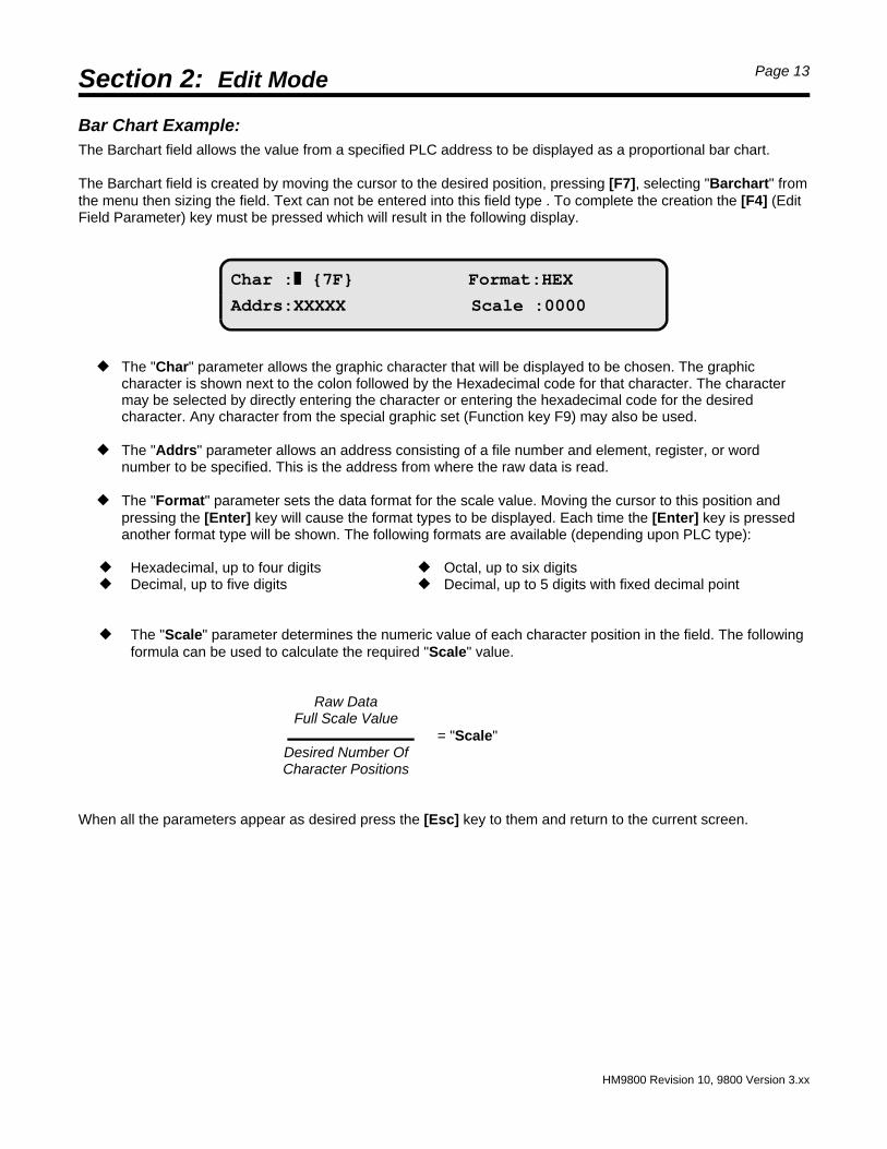
Bar Chart Example:The Barchart field allows the value from a specified PLC address to be displayed as a proportional bar chart.
The Barchart field is created by moving the cursor to the desired position, pressing [F7], selecting "Barchart" fromthe menu then sizing the field. Text can not be entered into this field type . To complete the creation the [F4] (EditField Parameter) key must be pressed which will result in the following display.
— The "Char" parameter allows the graphic character that will be displayed to be chosen. The graphiccharacter is shown next to the colon followed by the Hexadecimal code for that character. The charactermay be selected by directly entering the character or entering the hexadecimal code for the desiredcharacter. Any character from the special graphic set (Function key F9) may also be used.
— The "Addrs" parameter allows an address consisting of a file number and element, register, or word number to be specified. This is the address from where the raw data is read.
— The "Format" parameter sets the data format for the scale value. Moving the cursor to this position andpressing the [Enter] key will cause the format types to be displayed. Each time the [Enter] key is pressedanother format type will be shown. The following formats are available (depending upon PLC type):
— Hexadecimal, up to four digits — Octal, up to six digits— Decimal, up to five digits — Decimal, up to 5 digits with fixed decimal point
— The "Scale" parameter determines the numeric value of each character position in the field. The followingformula can be used to calculate the required "Scale" value.
Raw DataFull Scale Value
= "Scale"Desired Number OfCharacter Positions
When all the parameters appear as desired press the [Esc] key to them and return to the current screen.
Section 2: Edit Mode Page 14
HM9800 Revision 10, 9800 Version 3.xx
Printer Control CodesWhen a screen is sent to the COM1 serial communication port, all eighty characters that would appear on thedisplay are sent. When connected to a computer or certain printers this may not be sufficient for proper operation.For example, some printers require a Carriage Return or Line Feed character at the end of a transmission. The9800 includes a Control Code feature which allows these extra characters to be added to the screen text. In fact,special characters may be included ahead of the screen text, within the screen text, or after the screen text.
To access this feature the 9800 must be in the edit screen mode. If the [F10] key (Edit Ctrl Codes) is pressed thedisplay will blank except for a flashing block cursor in the HOME position. Before entering the Control Code screenit is important to determine where and what control codes must be included. A control code is entered byspecifying a position and the control code.
— The position is a decimal value from 0 to 80. The display characters are numbered from 0 to 79 starting atthe top left character position and ending at the bottom right character position. Specifying a position of zerowill cause the control code to be sent prior to the start of the screen text. Specifying a position of eighty willcause the control code to be sent after the screen text. When a character position within the screen text isspecified the control code will always be sent prior to the screen character. The control code can be anyhexadecimal value from 01 to FF.
The syntax for entering control codes is: @ Position : Control Code. For example, to send a Carriage Return (CR0Dhex) after the first forty characters (0 through 39) of screen text have been sent the following would be entered: @40:0D. Note the position was set to forty which will cause the control code to be sent prior to screen characterforty which is actually the forty first character.
— Up to 120 characters of control code information may be entered in to the control code screen. A spacecharacter must be included between each control code that is entered and is included in the 120 characterboundary.
When more than one control code is to be sent in a row it is not necessary to enter the position for each controlcode. For example, if after the entire screen text is sent a Carriage Return (CR 0Dhex) and a Line Feed (LF0Ahex) are to be sent, the following would be entered: @80:0D 0A.
Two control codes are reserved and have predefined functions. Control code 14 is used to terminate serialtransmission at the position where the code is specified. Control code 11 is used to multiple transmit a particularcode. The syntax for this is: @ Position : 11 Space Repetitions Space Code. For example, to transmit five LineFeeds at the end of a screen enter: @80:11 05 0A. All values are hexidecimal except the position value which isdecimal.
Example using several codes:
Start of Text character (STX 02hex) is to be sent prior to any screen text. After the first forty characters a Carriage Return and Line Feed are to be sent. After all eighty characters have been sent an End of Text character (ETX 03hex) is to be sent.
— Enter this: @00:02 @40:0D 0A @80:03
Note: When cloning a screen the control codes are also cloned.
Section 3: System Setups Page 15
HM9800 Revision 10, 9800 Version 3.xx
COM1 data port Date/Time PLC port
User keys/LED System
Baud rate:9600 Data bits:8 Type:RS232
Parity :Off Stop bits:1 Save setup
Date:03/11/92 Calibrate:000
Time:08:00:00 Save setup
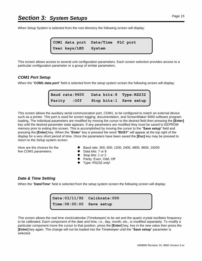
When Setup System is selected from the root directory the following screen will display:
This screen allows access to several unit configuration parameters. Each screen selection provides access to aparticular configuration parameter or a group of similar parameters.
COM1 Port SetupWhen the "COM1 data port" field is selected from the setup system screen the following screen will display:
This screen allows the auxiliary serial communication port, COM1, to be configured to match an external devicesuch as a printer. This port is used for screen logging, documentation, and ScreenMaker 9000 software programloading. The individual parameters are modified by moving the cursor to the desired field then pressing the [Enter]key until the desired parameter state appears. If any parameters are modified they must be saved to EEPROMmemory prior to exiting this screen. This is accomplished by moving the cursor to the "Save setup" field andpressing the [Enter] key. When the "Enter" key is pressed the word "BUSY" will appear at the top right of thedisplay for a very short period of time. Once the parameters have been saved the [Esc] key may be pressed toreturn to the Setup system screen.
Here are the choices for the — Baud rate: 300, 600, 1200, 2400, 4800, 9600, 19200five COM1 parameters: — Data bits: 7 or 8
— Stop bits: 1 or 2— Parity: Even, Odd, Off — Type: RS232 only!
Date & Time SettingWhen the "Date/Time" field is selected from the setup system screen the following screen will display:
This screen allows the real time clock/calendar (Timekeeper) to be set and the quartz crystal oscillator frequencyto be calibrated. Each component of the date and time, i.e., day, month, etc., is modified separately. To modify aparticular component move the cursor to that position, press the [Enter] key, key in the new value then press the[Enter] key again. The change will not be loaded into the Timekeeper until the "Save setup" parameter isselected.
Section 3: System Setups Page 16
HM9800 Revision 10, 9800 Version 3.xx
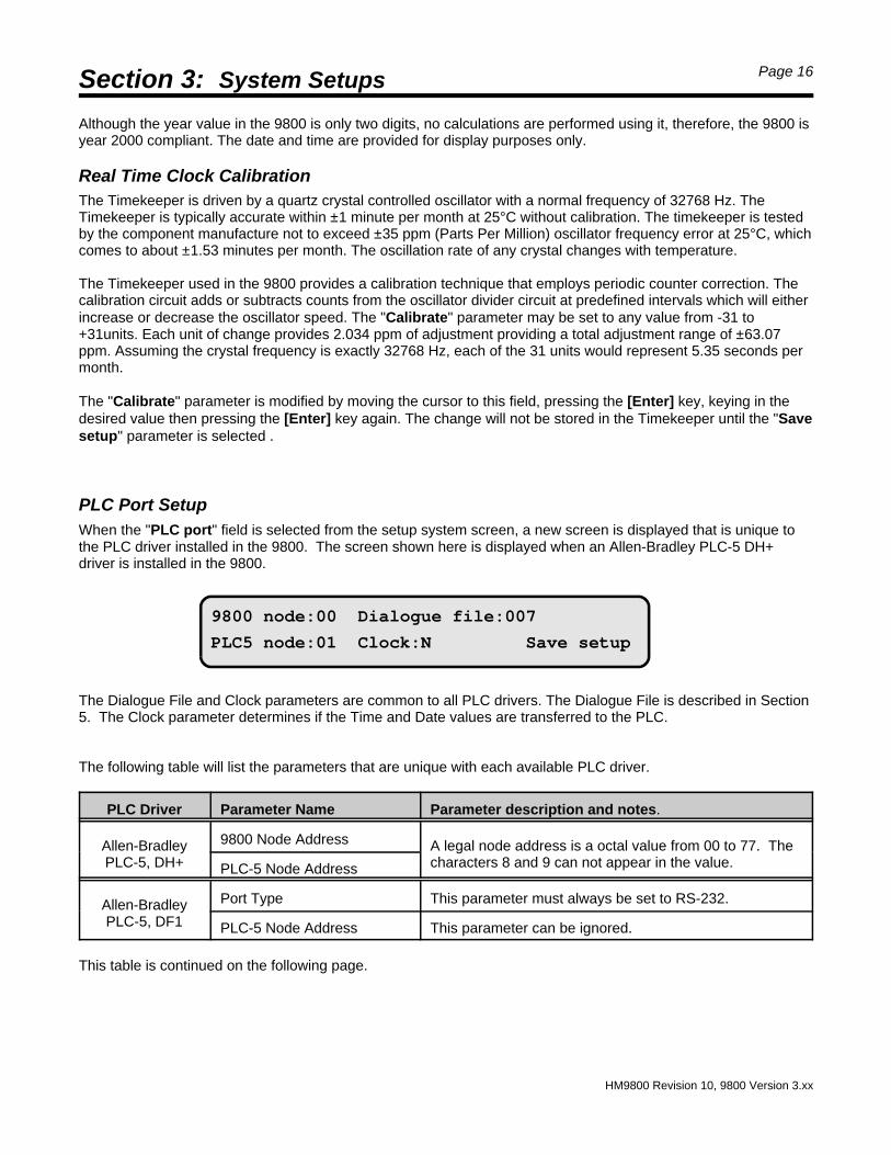
9800 node:00 Dialogue file:007
PLC5 node:01 Clock:N Save setup
Although the year value in the 9800 is only two digits, no calculations are performed using it, therefore, the 9800 isyear 2000 compliant. The date and time are provided for display purposes only.
Real Time Clock CalibrationThe Timekeeper is driven by a quartz crystal controlled oscillator with a normal frequency of 32768 Hz. TheTimekeeper is typically accurate within ±1 minute per month at 25°C without calibration. The timekeeper is testedby the component manufacture not to exceed ±35 ppm (Parts Per Million) oscillator frequency error at 25°C, whichcomes to about ±1.53 minutes per month. The oscillation rate of any crystal changes with temperature.
The Timekeeper used in the 9800 provides a calibration technique that employs periodic counter correction. Thecalibration circuit adds or subtracts counts from the oscillator divider circuit at predefined intervals which will eitherincrease or decrease the oscillator speed. The "Calibrate" parameter may be set to any value from -31 to+31units. Each unit of change provides 2.034 ppm of adjustment providing a total adjustment range of ±63.07ppm. Assuming the crystal frequency is exactly 32768 Hz, each of the 31 units would represent 5.35 seconds permonth.
The "Calibrate" parameter is modified by moving the cursor to this field, pressing the [Enter] key, keying in thedesired value then pressing the [Enter] key again. The change will not be stored in the Timekeeper until the "Savesetup" parameter is selected .
PLC Port SetupWhen the "PLC port" field is selected from the setup system screen, a new screen is displayed that is unique tothe PLC driver installed in the 9800. The screen shown here is displayed when an Allen-Bradley PLC-5 DH+driver is installed in the 9800.
The Dialogue File and Clock parameters are common to all PLC drivers. The Dialogue File is described in Section5. The Clock parameter determines if the Time and Date values are transferred to the PLC.
The following table will list the parameters that are unique with each available PLC driver.
PLC Driver Parameter Name Parameter description and notes.
Allen-BradleyPLC-5, DH+
9800 Node Address A legal node address is a octal value from 00 to 77. Thecharacters 8 and 9 can not appear in the value.PLC-5 Node Address
Allen-BradleyPLC-5, DF1
Port Type This parameter must always be set to RS-232.
PLC-5 Node Address This parameter can be ignored.
This table is continued on the following page.
Section 3: System Setups Page 17
HM9800 Revision 10, 9800 Version 3.xx
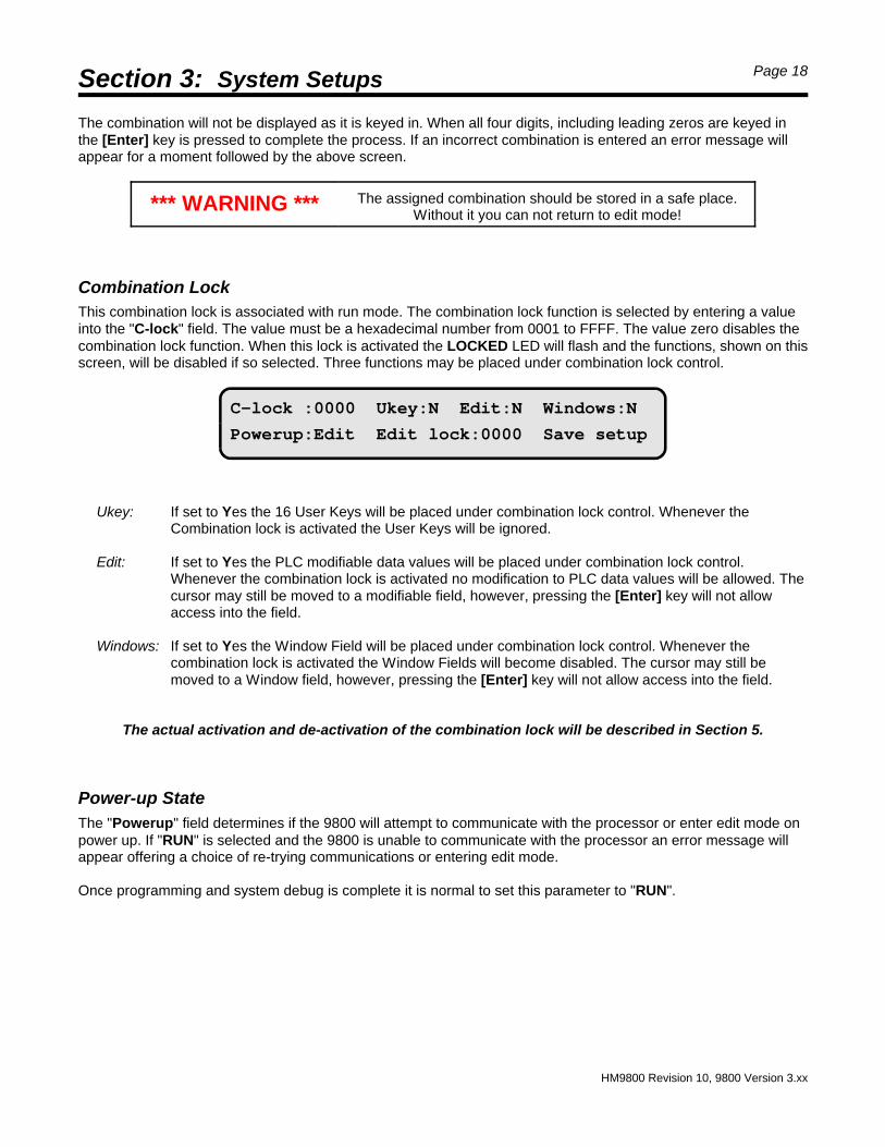
C-lock :0000 Ukey:N Edit:N Windows:N
Powerup:Edit Edit lock:0000 Save setup
**** Enter the Edit Mode lock value ****
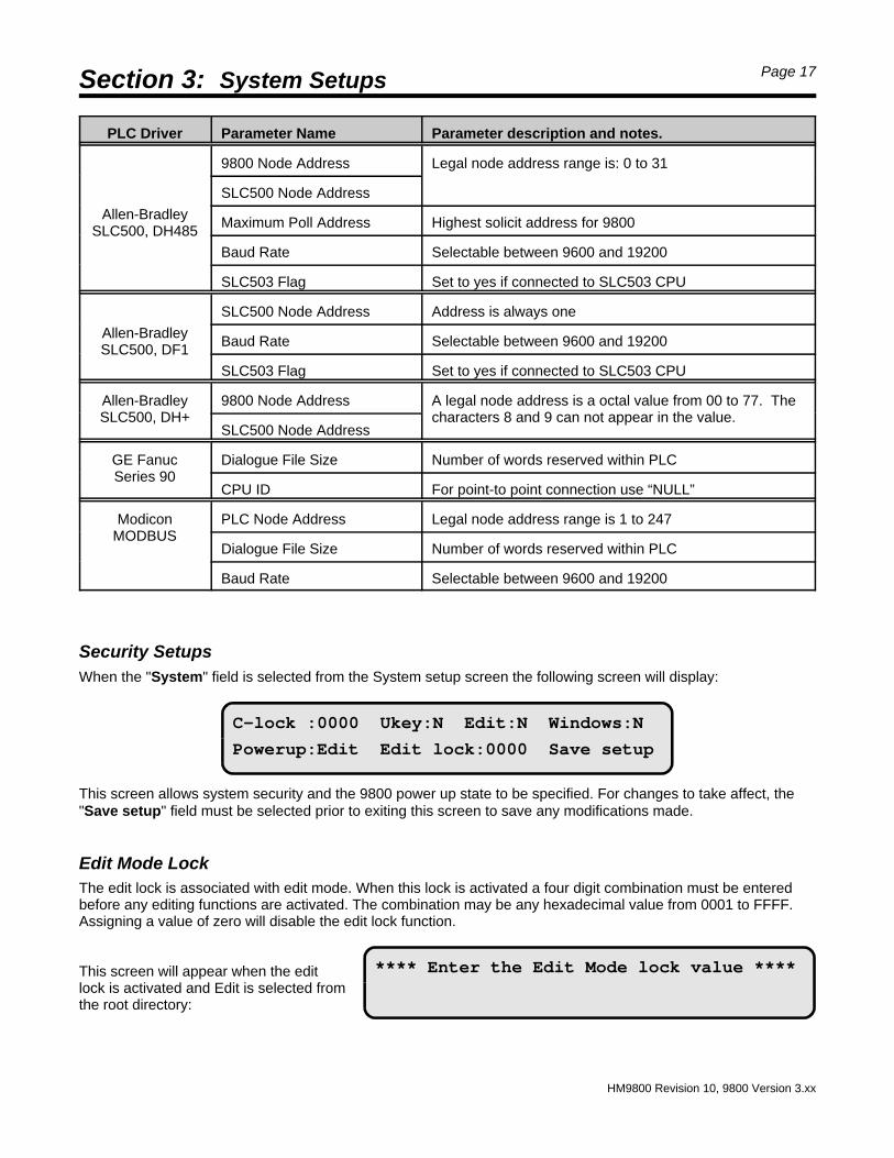
PLC Driver Parameter Name Parameter description and notes.
Allen-BradleySLC500, DH485
9800 Node Address Legal node address range is: 0 to 31
SLC500 Node Address
Maximum Poll Address Highest solicit address for 9800
Baud Rate Selectable between 9600 and 19200
SLC503 Flag Set to yes if connected to SLC503 CPU
Allen-BradleySLC500, DF1
SLC500 Node Address Address is always one
Baud Rate Selectable between 9600 and 19200
SLC503 Flag Set to yes if connected to SLC503 CPU
Allen-BradleySLC500, DH+
9800 Node Address A legal node address is a octal value from 00 to 77. Thecharacters 8 and 9 can not appear in the value.
SLC500 Node Address
GE FanucSeries 90
Dialogue File Size Number of words reserved within PLC
CPU ID For point-to point connection use “NULL”
ModiconMODBUS
PLC Node Address Legal node address range is 1 to 247
Dialogue File Size Number of words reserved within PLC
Baud Rate Selectable between 9600 and 19200
Security SetupsWhen the "System" field is selected from the System setup screen the following screen will display:
This screen allows system security and the 9800 power up state to be specified. For changes to take affect, the"Save setup" field must be selected prior to exiting this screen to save any modifications made.
Edit Mode LockThe edit lock is associated with edit mode. When this lock is activated a four digit combination must be enteredbefore any editing functions are activated. The combination may be any hexadecimal value from 0001 to FFFF.Assigning a value of zero will disable the edit lock function.
This screen will appear when the editlock is activated and Edit is selected fromthe root directory:
Section 3: System Setups Page 18
HM9800 Revision 10, 9800 Version 3.xx
C-lock :0000 Ukey:N Edit:N Windows:N
Powerup:Edit Edit lock:0000 Save setup
The combination will not be displayed as it is keyed in. When all four digits, including leading zeros are keyed inthe [Enter] key is pressed to complete the process. If an incorrect combination is entered an error message willappear for a moment followed by the above screen.
*** WARNING *** The assigned combination should be stored in a safe place.Without it you can not return to edit mode!
Combination LockThis combination lock is associated with run mode. The combination lock function is selected by entering a valueinto the "C-lock" field. The value must be a hexadecimal number from 0001 to FFFF. The value zero disables thecombination lock function. When this lock is activated the LOCKED LED will flash and the functions, shown on thisscreen, will be disabled if so selected. Three functions may be placed under combination lock control.
Ukey: If set to Yes the 16 User Keys will be placed under combination lock control. Whenever theCombination lock is activated the User Keys will be ignored.
Edit: If set to Yes the PLC modifiable data values will be placed under combination lock control.Whenever the combination lock is activated no modification to PLC data values will be allowed. Thecursor may still be moved to a modifiable field, however, pressing the [Enter] key will not allowaccess into the field.
Windows: If set to Yes the Window Field will be placed under combination lock control. Whenever thecombination lock is activated the Window Fields will become disabled. The cursor may still bemoved to a Window field, however, pressing the [Enter] key will not allow access into the field.
The actual activation and de-activation of the combination lock will be described in Section 5.
Power-up StateThe "Powerup" field determines if the 9800 will attempt to communicate with the processor or enter edit mode onpower up. If "RUN" is selected and the 9800 is unable to communicate with the processor an error message willappear offering a choice of re-trying communications or entering edit mode.
Once programming and system debug is complete it is normal to set this parameter to "RUN".
Section 3: System Setups Page 19
HM9800 Revision 10, 9800 Version 3.xx
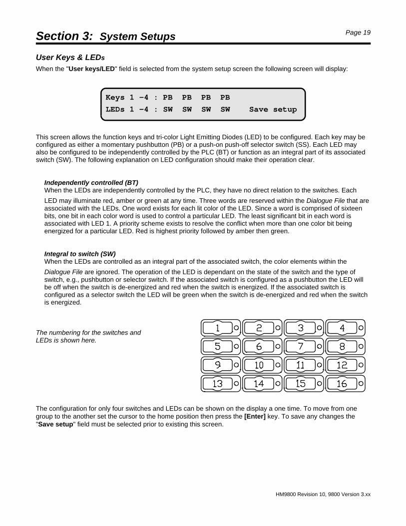
Keys 1 -4 : PB PB PB PB
LEDs 1 -4 : SW SW SW SW Save setup
User Keys & LEDs
When the "User keys/LED" field is selected from the system setup screen the following screen will display:
This screen allows the function keys and tri-color Light Emitting Diodes (LED) to be configured. Each key may beconfigured as either a momentary pushbutton (PB) or a push-on push-off selector switch (SS). Each LED mayalso be configured to be independently controlled by the PLC (BT) or function as an integral part of its associatedswitch (SW). The following explanation on LED configuration should make their operation clear.
Independently controlled (BT)When the LEDs are independently controlled by the PLC, they have no direct relation to the switches. Each
LED may illuminate red, amber or green at any time. Three words are reserved within the Dialogue File that areassociated with the LEDs. One word exists for each lit color of the LED. Since a word is comprised of sixteenbits, one bit in each color word is used to control a particular LED. The least significant bit in each word isassociated with LED 1. A priority scheme exists to resolve the conflict when more than one color bit beingenergized for a particular LED. Red is highest priority followed by amber then green.
Integral to switch (SW)When the LEDs are controlled as an integral part of the associated switch, the color elements within the
Dialogue File are ignored. The operation of the LED is dependant on the state of the switch and the type ofswitch, e.g., pushbutton or selector switch. If the associated switch is configured as a pushbutton the LED willbe off when the switch is de-energized and red when the switch is energized. If the associated switch isconfigured as a selector switch the LED will be green when the switch is de-energized and red when the switchis energized.
The numbering for the switches and LEDs is shown here.
The configuration for only four switches and LEDs can be shown on the display a one time. To move from onegroup to the another set the cursor to the home position then press the [Enter] key. To save any changes the"Save setup" field must be selected prior to existing this screen.
Section 4: Utility Page 20
HM9800 Revision 10, 9800 Version 3.xx
PLC comm fault
Retry Reset
Screens 000 thru 000 Print setups
Print Delete Transfer data
When Utilities is selected from the root directory the following screen will display:
This screen allows a contiguous group of screens to be deleted or documented to a printer. It also allowsdocumenting to a printer the configuration parameters contained in the Setup System screens. Another functionallows the uploading and downloading of screen files or program files.
Prior to deleting or printing a group of screens, the starting screen number and ending screen number must bekeyed in. When printing the COM1 serial port must first be configured using the Setup system screens. Printingthe configuration parameters also requires that COM1 first be configured.
The Transfer data field is used with Quartech ScreenMaker 9000 configuration software. Any special informationrequired will be included with the specific software package.
Selecting the Run Mode will cause the 9800 to attempt to establish communication with the PLC. The word"BUSY" will appear in the top right of the display to indicate status. If successful the unit will proceed with normaloperation. If the 9800 is not successful in establishing communication the following screen will display:
If "Retry" is selected the 9800 will again attempt to establish communication. If "Reset" is selected the 9800 willexecute a "Warm boot" ending at the edit root directory or at the edit mode combination screen. The AT keyboardmay be used to exit Run Mode by pressing the [Ctrl], [Alt], and [Delete] keys simultaneously. It is not possible toexit run mode from the 9800 keypad.
Notice! The keypad on the 9800 can be used to navigate through the EditMode screens if an AT keyboard is not connected to the unit.
Section 5: Run Mode Page 21
HM9800 Revision 10, 9800 Version 3.xx
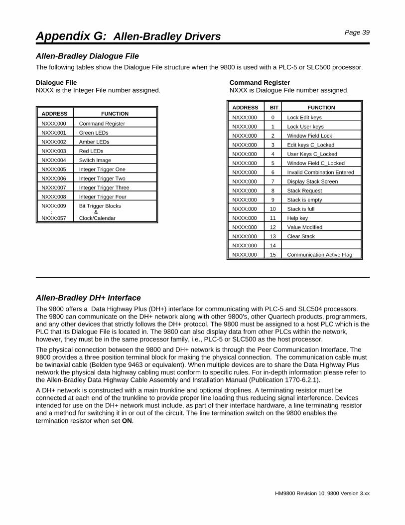
When in run mode the 9800 must share various information with the PLC. For example the 9800 must provide thePLC with the status of the User Keys; the PLC must dictate what screen(s) should be displayed at any particulartime. To accomplish these tasks a contiguous group of words, referred to as the Dialogue File, must be reservedin the PLC for use with the 9800.
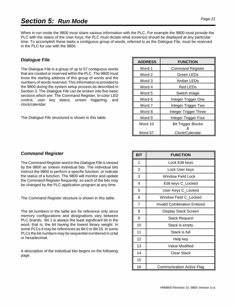
Dialogue File
The Dialogue File is a group of up to 57 contiguous wordsthat are created or reserved within the PLC. The 9800 mustknow the starting address of this group of words and thenumbers of words reserved. This information is provided tothe 9800 during the system setup process as described inSection 3. The Dialogue File can be broken into five basicsections which are: The Command Register, tri-color LEDcontrol, user key status, screen triggering, andclock/calendar.
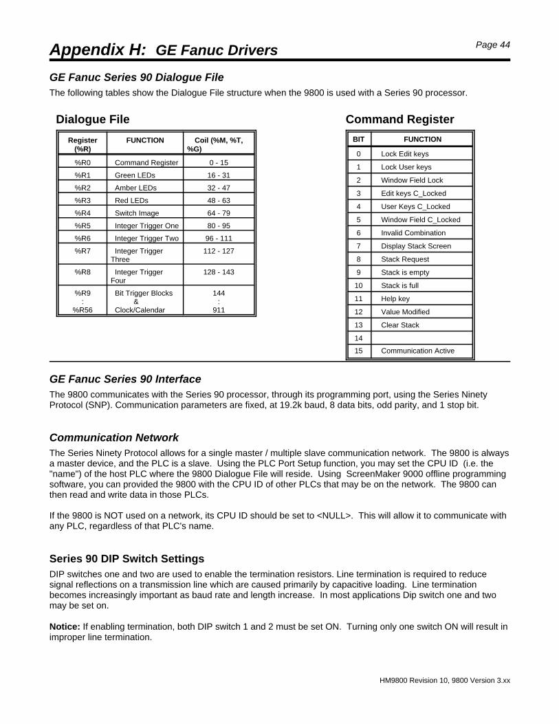
The Dialogue File structured is shown in this table.
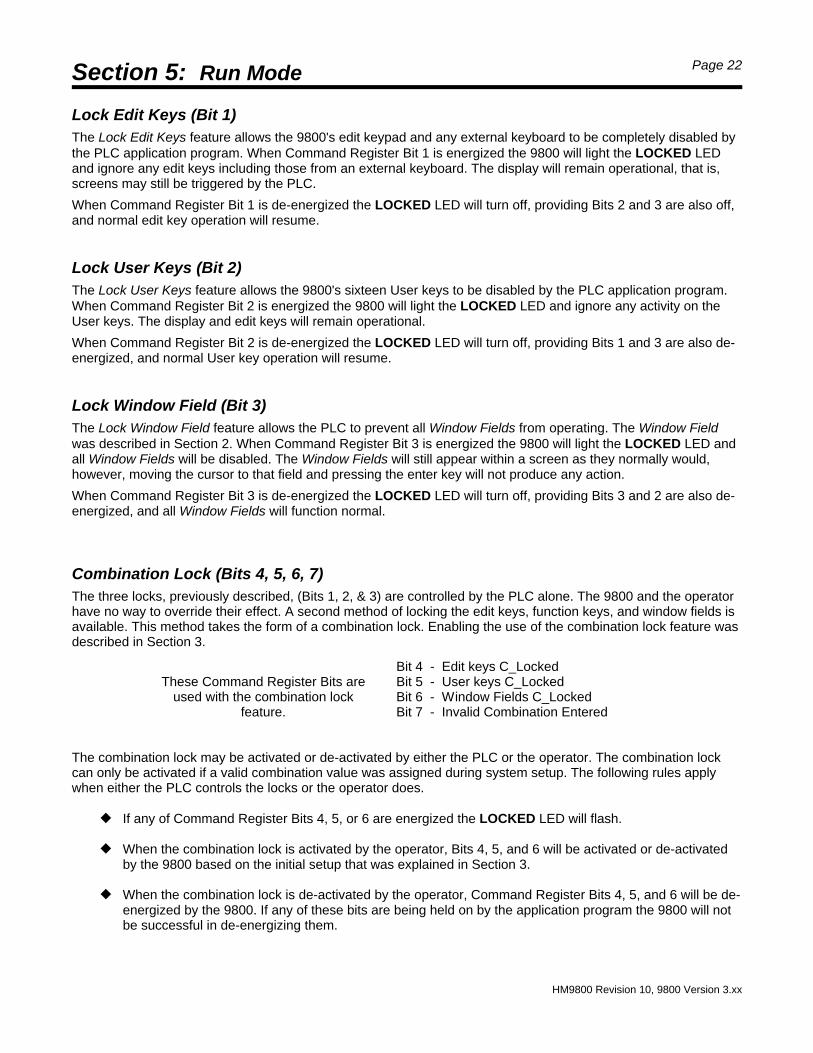
Command Register
The Command Register word in the Dialogue File is viewedby the 9800 as sixteen individual bits. The individual bitsinstruct the 9800 to perform a specific function, or indicatethe status of a function. The 9800 will monitor and updatethe Command Register frequently, so each of the bits maybe changed by the PLC application program at any time.
The Command Register structure is shown in this table.
The bit numbers in the table are for reference only sincememory configurations and designations vary betweenPLC brands. Bit 1 is always the least significant bit in theword, that is, the bit having the lowest binary weight. Insome PLCs it may be references as Bit 0 or Bit 16. In somePLCs the bit numbers may be sequential numbered in octalor hexadecimal.
A description of the individual bits begins on the followingpage.
ADDRESS FUNCTION
Word 1 Command Register
Word 2 Green LEDs
Word 3 Amber LEDs
Word 4 Red LEDs
Word 5 Switch Image
Word 6 Integer Trigger One
Word 7 Integer Trigger Two
Word 8 Integer Trigger Three
Word 9 Integer Trigger Four
Word 10:
Word 57
Bit Trigger Blocks&
Clock/Calendar
BIT FUNCTION
1 Lock Edit keys
2 Lock User keys
3 Window Field Lock
4 Edit keys C_Locked
5 User Keys C_Locked
6 Window Field C_Locked
7 Invalid Combination Entered
8 Display Stack Screen
9 Stack Request
10 Stack is empty
11 Stack is full
12 Help key
13 Value Modified
14 Clear Stack
15
16 Communication Active Flag
Section 5: Run Mode Page 22
HM9800 Revision 10, 9800 Version 3.xx
Lock Edit Keys (Bit 1)The Lock Edit Keys feature allows the 9800's edit keypad and any external keyboard to be completely disabled bythe PLC application program. When Command Register Bit 1 is energized the 9800 will light the LOCKED LEDand ignore any edit keys including those from an external keyboard. The display will remain operational, that is,screens may still be triggered by the PLC.
When Command Register Bit 1 is de-energized the LOCKED LED will turn off, providing Bits 2 and 3 are also off,and normal edit key operation will resume.
Lock User Keys (Bit 2)The Lock User Keys feature allows the 9800's sixteen User keys to be disabled by the PLC application program.When Command Register Bit 2 is energized the 9800 will light the LOCKED LED and ignore any activity on theUser keys. The display and edit keys will remain operational.
When Command Register Bit 2 is de-energized the LOCKED LED will turn off, providing Bits 1 and 3 are also de-energized, and normal User key operation will resume.
Lock Window Field (Bit 3)The Lock Window Field feature allows the PLC to prevent all Window Fields from operating. The Window Fieldwas described in Section 2. When Command Register Bit 3 is energized the 9800 will light the LOCKED LED andall Window Fields will be disabled. The Window Fields will still appear within a screen as they normally would,however, moving the cursor to that field and pressing the enter key will not produce any action.
When Command Register Bit 3 is de-energized the LOCKED LED will turn off, providing Bits 3 and 2 are also de-energized, and all Window Fields will function normal.
Combination Lock (Bits 4, 5, 6, 7)The three locks, previously described, (Bits 1, 2, & 3) are controlled by the PLC alone. The 9800 and the operatorhave no way to override their effect. A second method of locking the edit keys, function keys, and window fields isavailable. This method takes the form of a combination lock. Enabling the use of the combination lock feature wasdescribed in Section 3.
These Command Register Bits areused with the combination lock
feature.
Bit 4 - Edit keys C_Locked Bit 5 - User keys C_Locked Bit 6 - Window Fields C_Locked Bit 7 - Invalid Combination Entered
The combination lock may be activated or de-activated by either the PLC or the operator. The combination lockcan only be activated if a valid combination value was assigned during system setup. The following rules applywhen either the PLC controls the locks or the operator does.
— If any of Command Register Bits 4, 5, or 6 are energized the LOCKED LED will flash.
— When the combination lock is activated by the operator, Bits 4, 5, and 6 will be activated or de-activatedby the 9800 based on the initial setup that was explained in Section 3.
— When the combination lock is de-activated by the operator, Command Register Bits 4, 5, and 6 will be de-energized by the 9800. If any of these bits are being held on by the application program the 9800 will notbe successful in de-energizing them.
Section 5: Run Mode Page 23
HM9800 Revision 10, 9800 Version 3.xx
— The PLC may energize a bit that can not be energized by the 9800. For example if User keys were notselected for combination lock control during setup, the PLC may energize the corresponding bit and lockthe User keys.
— The 9800 can not override bits within the command register that are being held energized or de-energizedby the PLC's application program. The PLC can override the 9800.
The operator activates the combination lock by pressing the [LOCK] key. This will start the LOCKED LED flashingand the selected locks will be enforced. De-activating the combination by the operator requires the correct fourdigit combination value being keyed into the 9800. The process is started by pressing the [LOCK] key. Next, thefour digit combination value must be entered including any leading zeros, followed by the [ENT] key. If thecombination value is correct and the PLC is not forcing the combination lock feature on the LOCKED LED will stopflashing and normal operation will resume. If an incorrect combination value is entered the 9800 will energizeCommand Register Bit 7 .
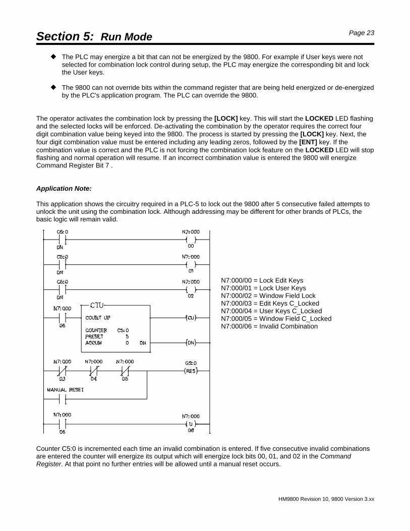
Application Note:
This application shows the circuitry required in a PLC-5 to lock out the 9800 after 5 consecutive failed attempts tounlock the unit using the combination lock. Although addressing may be different for other brands of PLCs, thebasic logic will remain valid.
N7:000/00 = Lock Edit Keys N7:000/01 = Lock User Keys N7:000/02 = Window Field Lock N7:000/03 = Edit Keys C_Locked N7:000/04 = User Keys C_Locked N7:000/05 = Window Field C_Locked N7:000/06 = Invalid Combination
Counter C5:0 is incremented each time an invalid combination is entered. If five consecutive invalid combinationsare entered the counter will energize its output which will energize lock bits 00, 01, and 02 in the CommandRegister. At that point no further entries will be allowed until a manual reset occurs.
Section 5: Run Mode Page 24
HM9800 Revision 10, 9800 Version 3.xx
****** The screen stack is empty ******
Screen Stack (Bits 8, 9, 10, 11, 14) When screens are created one of the attribute flags allows the screens to be placed within a stack that residesinside the 9800's RAM memory. Up to 100 screens may be in the stack at any time.
These five Bits in the Command Registerare associated with the Stack feature.
< Bit 8 - Display Stack Screen< Bit 9 - Stack Request< Bit 10 - Stack is Empty< Bit 11 - Stack is Full< Bit 14 - Clear Stack
A special screen, number 720, is associated with the screen stack feature. Screen 720 will be displayed whenCommand Register Bit 8 is energized to enable stack screen display, and no stacked screens are present. Screen720 may be modified or re-sized with the resident editor, however it can not be deleted.
Screen 720 looks like thisas shipped from the factory.
The following points describe the basic features offered by the screen stack.
— To direct a screen to the stack the "Stack" flag must be set to Yes. See Section 2 for information on theEdit Screen Flags function.
— Command Register Bit 8 (Display Stack Screen) enables stacked screens to be displayed. This bit iscontrolled by the PLC, however, through ladder logic one of the 9800 User Keys may be used to energizeor de-energize it.
— When Command Register Bit 9 (Stack Request) is energized the next screen on the stack will be movedto the display. If there are no screens in the stack, screen 720 will automatically be displayed. This bit iscontrolled by the PLC, however, through ladder logic one of the 9800 User Keys may be used to energizeor de-energize it.
— Command Register Bit 10 (Stack is Empty) will be energized by the 9800 when no screens are in thestack. It is at this time that screen 720 is displayed. The 9800 will de-energize this bit when at least onescreen is in the stack.
— Command Register Bit 11 (Stack is Full) will be energized by the 9800 when one hundred screens are inthe stack. While this bit is energized no additional screens will be accepted by the stack, they will be lost.The 9800 will de-energize this bit when the number of screens in the stack falls below one hundred.
— When Command Register Bit 14 (Clear Stack) is energized all screens that are in the stack are deletedleaving the stack empty.
Help Key (Bit 12)This Command Register bit is controlled by the [HELP] key in the 9800's edit keypad. The [HELP] key functionslike a pushbutton. When the [HELP] key is pressed the 9800 will energize Command Register Bit 12. When the[HELP] key is released the 9800 will de-energize Bit 12. The actual use and implementation of this feature is leftup to the programmer.
Section 5: Run Mode Page 25
HM9800 Revision 10, 9800 Version 3.xx
Value Modified (Bit 13)Command Register bit 13 is energized by the 9800 any time a screen sends data to the PLC. This includes DataSet Fields, PLC Data Fields, and Bit Status Fields when used in the bit set format. The 9800 does not de-energizethis bit, therefore the PLC application program must acknowledge the modification by de-energizing the bit eachtime it is set. If this function is not used by the PLC application program then it may simply be ignored.
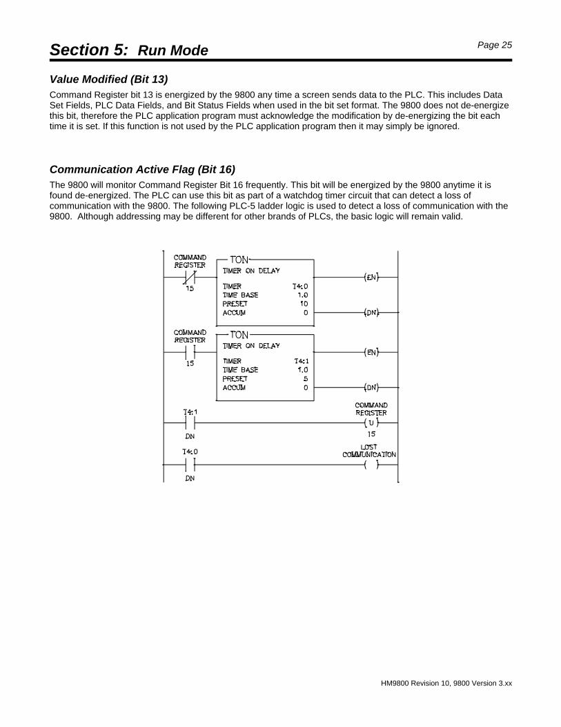
Communication Active Flag (Bit 16)The 9800 will monitor Command Register Bit 16 frequently. This bit will be energized by the 9800 anytime it isfound de-energized. The PLC can use this bit as part of a watchdog timer circuit that can detect a loss ofcommunication with the 9800. The following PLC-5 ladder logic is used to detect a loss of communication with the9800. Although addressing may be different for other brands of PLCs, the basic logic will remain valid.
Section 5: Run Mode Page 26
HM9800 Revision 10, 9800 Version 3.xx
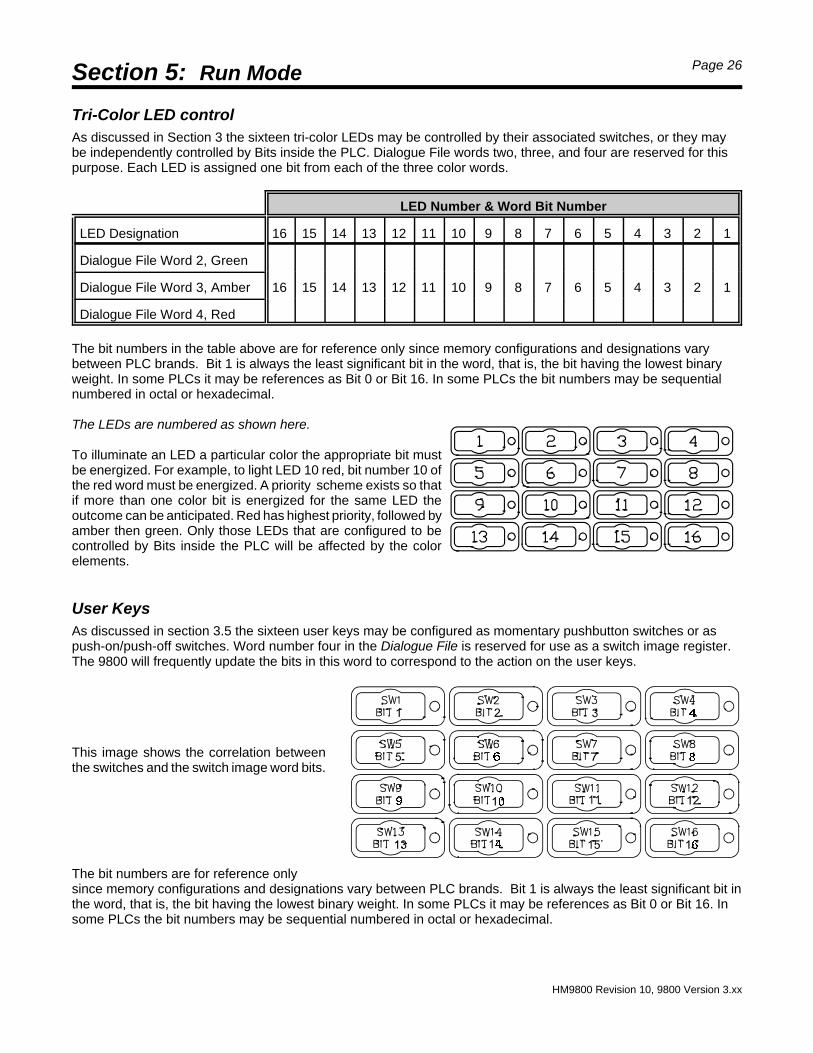
Tri-Color LED controlAs discussed in Section 3 the sixteen tri-color LEDs may be controlled by their associated switches, or they maybe independently controlled by Bits inside the PLC. Dialogue File words two, three, and four are reserved for thispurpose. Each LED is assigned one bit from each of the three color words.
The bit numbers in the table above are for reference only since memory configurations and designations varybetween PLC brands. Bit 1 is always the least significant bit in the word, that is, the bit having the lowest binaryweight. In some PLCs it may be references as Bit 0 or Bit 16. In some PLCs the bit numbers may be sequentialnumbered in octal or hexadecimal.
The LEDs are numbered as shown here.
To illuminate an LED a particular color the appropriate bit mustbe energized. For example, to light LED 10 red, bit number 10 ofthe red word must be energized. A priority scheme exists so thatif more than one color bit is energized for the same LED theoutcome can be anticipated. Red has highest priority, followed byamber then green. Only those LEDs that are configured to becontrolled by Bits inside the PLC will be affected by the colorelements.
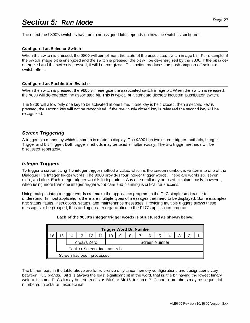
User KeysAs discussed in section 3.5 the sixteen user keys may be configured as momentary pushbutton switches or aspush-on/push-off switches. Word number four in the Dialogue File is reserved for use as a switch image register.The 9800 will frequently update the bits in this word to correspond to the action on the user keys.
This image shows the correlation betweenthe switches and the switch image word bits.
The bit numbers are for reference onlysince memory configurations and designations vary between PLC brands. Bit 1 is always the least significant bit inthe word, that is, the bit having the lowest binary weight. In some PLCs it may be references as Bit 0 or Bit 16. Insome PLCs the bit numbers may be sequential numbered in octal or hexadecimal.
Section 5: Run Mode Page 27
HM9800 Revision 10, 9800 Version 3.xx
The effect the 9800's switches have on their assigned bits depends on how the switch is configured.
Configured as Selector Switch -
When the switch is pressed, the 9800 will compliment the state of the associated switch image bit. For example, ifthe switch image bit is energized and the switch is pressed, the bit will be de-energized by the 9800. If the bit is de-energized and the switch is pressed, it will be energized. This action produces the push-on/push-off selectorswitch effect. Configured as Pushbutton Switch -
When the switch is pressed, the 9800 will energize the associated switch image bit. When the switch is released,the 9800 will de-energize the associated bit. This is typical of a standard discrete industrial pushbutton switch.
The 9800 will allow only one key to be activated at one time. If one key is held closed, then a second key ispressed, the second key will not be recognized. If the previously closed key is released the second key will berecognized.
Screen TriggeringA trigger is a means by which a screen is made to display. The 9800 has two screen trigger methods, IntegerTrigger and Bit Trigger. Both trigger methods may be used simultaneously. The two trigger methods will bediscussed separately.
Integer TriggersTo trigger a screen using the integer trigger method a value, which is the screen number, is written into one of theDialogue File Integer trigger words. The 9800 provides four integer trigger words. These are words six, seven,eight, and nine. Each integer trigger word is independent. Any one or all may be used simultaneously; however,when using more than one integer trigger word care and planning is critical for success.
Using multiple integer trigger words can make the application program in the PLC simpler and easier tounderstand. In most applications there are multiple types of messages that need to be displayed. Some examplesare: status, faults, instructions, setups, and maintenance messages. Providing multiple triggers allows thesemessages to be grouped, thus adding greater organization to the PLC's application program.
Each of the 9800's integer trigger words is structured as shown below.
Trigger Word Bit Number
16 15 14 13 12 11 10 9 8 7 6 5 4 3 2 1
Always Zero Screen Number
Fault or Screen does not exist
Screen has been processed
The bit numbers in the table above are for reference only since memory configurations and designations varybetween PLC brands. Bit 1 is always the least significant bit in the word, that is, the bit having the lowest binaryweight. In some PLCs it may be references as Bit 0 or Bit 16. In some PLCs the bit numbers may be sequentialnumbered in octal or hexadecimal.
Section 5: Run Mode Page 28
HM9800 Revision 10, 9800 Version 3.xx
Since the screen number can not be greater than 722 only the ten least significant bits of the trigger words areused when a screen number is moved into it. The 9800 uses bits 15 & 16 to indicate status back to the PLC. The9800 will set (energize) bit 16 when the screen specified by bits 1 through 10 has been accepted for display, stack,or printing. If the screen does not exist, or has syntax errors, then bit 15 will also be set.
Displaying a screen is referred to as "opening a screen". Each time a new screen number is moved into aparticular trigger word, that screen number will be recognized by the 9800 and the screen will become open. Thenew screen will overwrite any screen previously specified by that trigger word. Removing a currently displayedscreen is referred to as "closing a screen". Only one screen may be open for each trigger word at any one time.It is possible to close a currently open screen without opening another to replace it. This is done by moving a valueof zero into the trigger word.
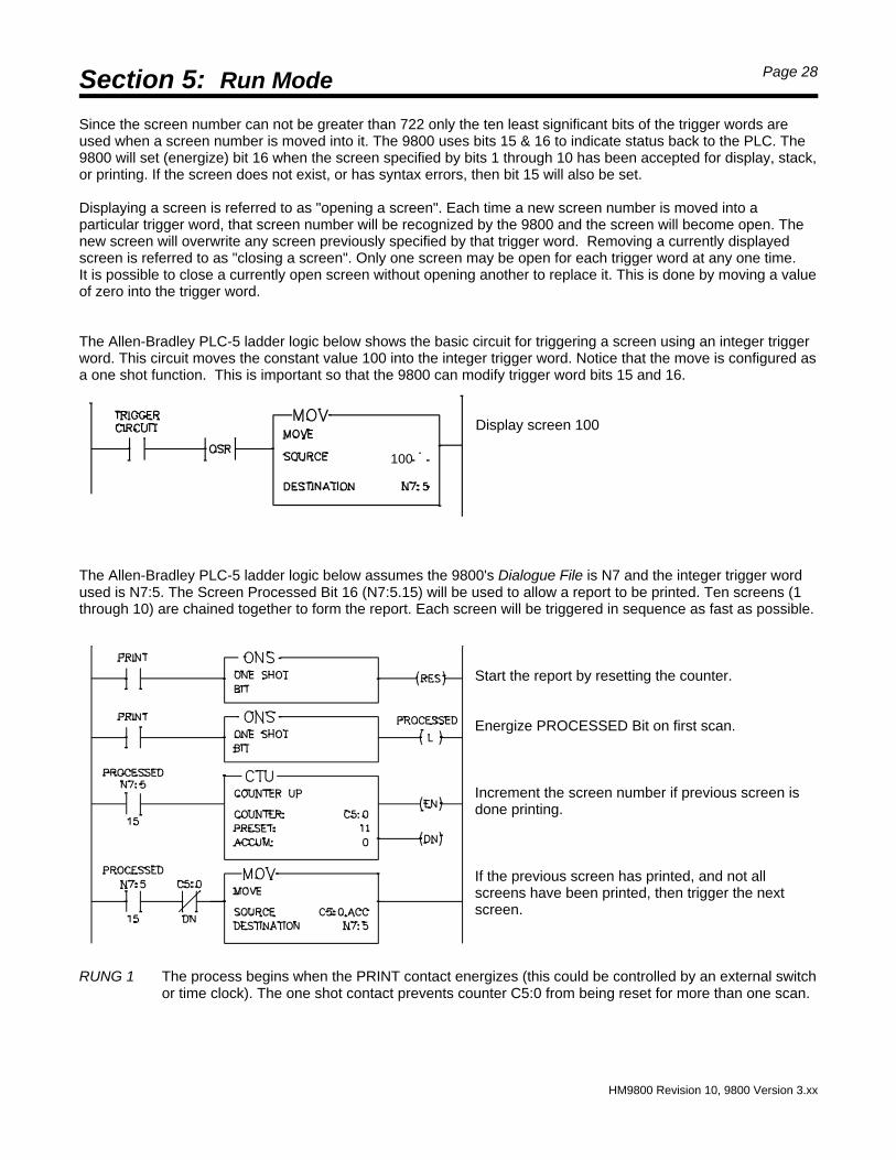
The Allen-Bradley PLC-5 ladder logic below shows the basic circuit for triggering a screen using an integer triggerword. This circuit moves the constant value 100 into the integer trigger word. Notice that the move is configured asa one shot function. This is important so that the 9800 can modify trigger word bits 15 and 16.
Display screen 100
100
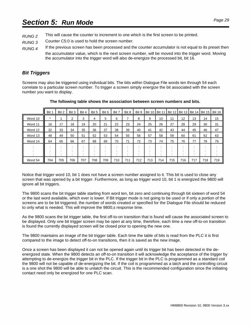
The Allen-Bradley PLC-5 ladder logic below assumes the 9800's Dialogue File is N7 and the integer trigger wordused is N7:5. The Screen Processed Bit 16 (N7:5.15) will be used to allow a report to be printed. Ten screens (1through 10) are chained together to form the report. Each screen will be triggered in sequence as fast as possible.
Start the report by resetting the counter.
Energize PROCESSED Bit on first scan.
Increment the screen number if previous screen isdone printing.
If the previous screen has printed, and not allscreens have been printed, then trigger the nextscreen.
RUNG 1 The process begins when the PRINT contact energizes (this could be controlled by an external switchor time clock). The one shot contact prevents counter C5:0 from being reset for more than one scan.
Section 5: Run Mode Page 29
HM9800 Revision 10, 9800 Version 3.xx
RUNG 2 This will cause the counter to increment to one which is the first screen to be printed.
RUNG 3 Counter C5:0 is used to hold the screen number.
RUNG 4 If the previous screen has been processed and the counter accumulator is not equal to its preset then
the accumulator value, which is the next screen number, will be moved into the trigger word. Movingthe accumulator into the trigger word will also de-energize the processed bit, bit 16.
Bit Triggers
Screens may also be triggered using individual bits. The bits within Dialogue File words ten through 54 eachcorrelate to a particular screen number. To trigger a screen simply energize the bit associated with the screennumber you want to display.
The following table shows the association between screen numbers and bits.
Bit 1 Bit 2 Bit 3 Bit 4 Bit 5 Bit 6 Bit 7 Bit 8 Bit 9 Bit 10 Bit 11 Bit 12 Bit 13 Bit 14 Bit 15 Bit 16
Notice that trigger word 10, bit 1 does not have a screen number assigned to it. This bit is used to close anyscreen that was opened by a bit trigger. Furthermore, as long as trigger word 10, bit 1 is energized the 9800 willignore all bit triggers.
The 9800 scans the bit trigger table starting from word ten, bit zero and continuing through bit sixteen of word 54 or the last word available, which ever is lower. If Bit trigger mode is not going to be used or if only a portion of thescreens are to be bit triggered, the number of words created or specified for the Dialogue File should be reducedto only what is needed. This will improve the 9800,s response time.
As the 9800 scans the bit trigger table, the first off-to-on transition that is found will cause the associated screen tobe displayed. Only one bit trigger screen may be open at any time, therefore, each time a new off-to-on transitionis found the currently displayed screen will be closed prior to opening the new one.
The 9800 maintains an image of the bit trigger table. Each time the table of bits is read from the PLC it is firstcompared to the image to detect off-to-on transitions, then it is saved as the new image.
Once a screen has been displayed it can not be opened again until its trigger bit has been detected in the de-energized state. When the 9800 detects an off-to-on transition it will acknowledge the acceptance of the trigger byattempting to de-energize the trigger bit in the PLC. If the trigger bit in the PLC is programmed as a standard coilthe 9800 will not be capable of de-energizing the bit. If the coil is programmed as a latch and the controlling circuitis a one shot the 9800 will be able to unlatch the circuit. This is the recommended configuration since the initiatingcontact need only be energized for one PLC scan.
Section 5: Run Mode Page 30
HM9800 Revision 10, 9800 Version 3.xx
Address:O000:000 Format:HEX
Data :0000
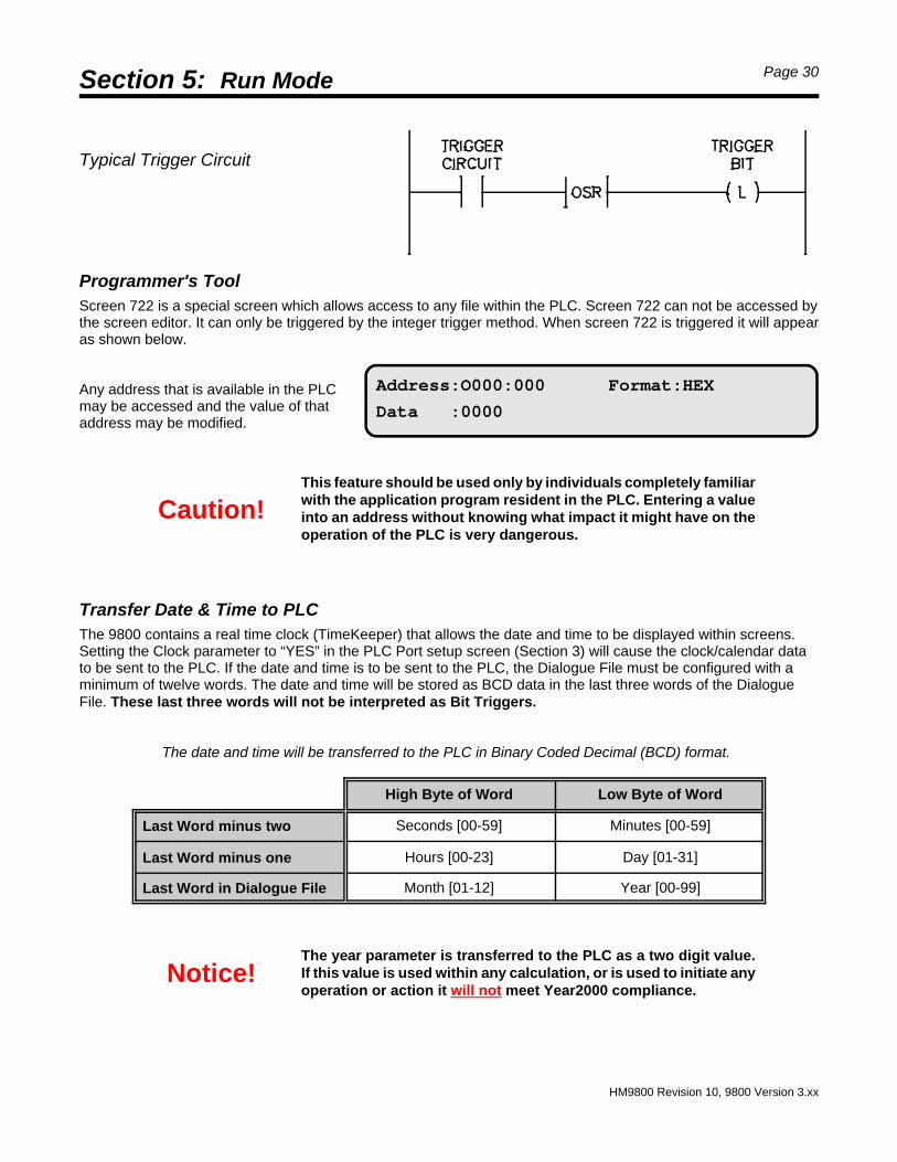
Typical Trigger Circuit
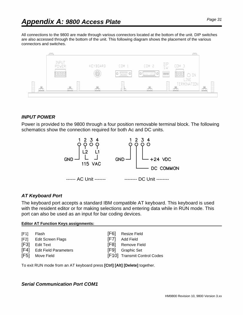
Programmer's ToolScreen 722 is a special screen which allows access to any file within the PLC. Screen 722 can not be accessed bythe screen editor. It can only be triggered by the integer trigger method. When screen 722 is triggered it will appearas shown below.
Any address that is available in the PLCmay be accessed and the value of thataddress may be modified.
Caution!This feature should be used only by individuals completely familiarwith the application program resident in the PLC. Entering a valueinto an address without knowing what impact it might have on theoperation of the PLC is very dangerous.
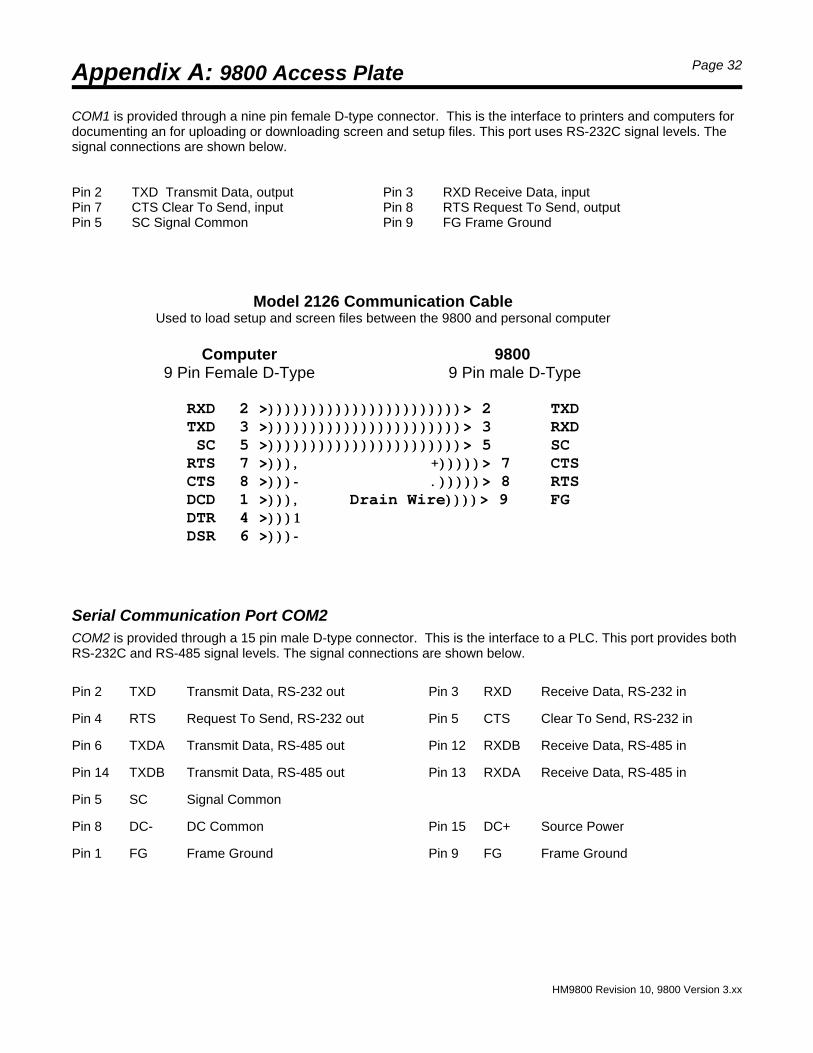
Transfer Date & Time to PLCThe 9800 contains a real time clock (TimeKeeper) that allows the date and time to be displayed within screens. Setting the Clock parameter to “YES” in the PLC Port setup screen (Section 3) will cause the clock/calendar datato be sent to the PLC. If the date and time is to be sent to the PLC, the Dialogue File must be configured with aminimum of twelve words. The date and time will be stored as BCD data in the last three words of the DialogueFile. These last three words will not be interpreted as Bit Triggers.
The date and time will be transferred to the PLC in Binary Coded Decimal (BCD) format.
High Byte of Word Low Byte of Word
Last Word minus two Seconds [00-59] Minutes [00-59]
Last Word minus one Hours [00-23] Day [01-31]
Last Word in Dialogue File Month [01-12] Year [00-99]
Notice!The year parameter is transferred to the PLC as a two digit value.If this value is used within any calculation, or is used to initiate anyoperation or action it will not meet Year2000 compliance.
Appendix A: 9800 Access Plate Page 31
HM9800 Revision 10, 9800 Version 3.xx
All connections to the 9800 are made through various connectors located at the bottom of the unit. DIP switchesare also accessed through the bottom of the unit. This following diagram shows the placement of the variousconnectors and switches.
INPUT POWER
Power is provided to the 9800 through a four position removable terminal block. The followingschematics show the connection required for both Ac and DC units.
------ AC Unit ------- -------- DC Unit --------
AT Keyboard Port
The keyboard port accepts a standard IBM compatible AT keyboard. This keyboard is usedwith the resident editor or for making selections and entering data while in RUN mode. Thisport can also be used as an input for bar coding devices.
Editor AT Function Keys assignments:
[F1] Flash [F6] Resize Field[F2] Edit Screen Flags [F7] Add Field[F3] Edit Text [F8] Remove Field[F4] Edit Field Parameters [F9] Graphic Set[F5] Move Field [F10] Transmit Control Codes
To exit RUN mode from an AT keyboard press [Ctrl] [Alt] [Delete] together.
Serial Communication Port COM1
Appendix A: 9800 Access Plate Page 32
HM9800 Revision 10, 9800 Version 3.xx
Model 2126 Communication CableUsed to load setup and screen files between the 9800 and personal computer
Computer 9800 9 Pin Female D-Type 9 Pin male D-Type
COM1 is provided through a nine pin female D-type connector. This is the interface to printers and computers fordocumenting an for uploading or downloading screen and setup files. This port uses RS-232C signal levels. Thesignal connections are shown below.
Pin 2 TXD Transmit Data, output Pin 3 RXD Receive Data, inputPin 7 CTS Clear To Send, input Pin 8 RTS Request To Send, outputPin 5 SC Signal Common Pin 9 FG Frame Ground
Serial Communication Port COM2COM2 is provided through a 15 pin male D-type connector. This is the interface to a PLC. This port provides bothRS-232C and RS-485 signal levels. The signal connections are shown below.
Pin 2 TXD Transmit Data, RS-232 out Pin 3 RXD Receive Data, RS-232 in
Pin 4 RTS Request To Send, RS-232 out Pin 5 CTS Clear To Send, RS-232 in
Pin 6 TXDA Transmit Data, RS-485 out Pin 12 RXDB Receive Data, RS-485 in
Pin 14 TXDB Transmit Data, RS-485 out Pin 13 RXDA Receive Data, RS-485 in
Pin 5 SC Signal Common
Pin 8 DC- DC Common Pin 15 DC+ Source Power
Pin 1 FG Frame Ground Pin 9 FG Frame Ground
Appendix A: 9800 Access Plate Page 33
HM9800 Revision 10, 9800 Version 3.xx
Serial Communication Port COM3COM3 is provided through a three position removable terminal block and is used to connect the 9800 to the Allen-Bradley PLC-5 and SLC500 DH+ network. For all other PLC driver types, this terminal is not present. The linetermination switch is set ON when the 9800 is a physical end node on the DH+ network.
DIP Switch AssignmentsThe four position DIP switch accessible through the cover is associated with communication port COM2. Thefunction of the individual switches is shown below.
Switch 1 240 ohm termination resistor for the RS-485 receiver.Switch 2 240 ohm termination resistor for the RS-485 receiver.
Switch 3 Enable RS-485 interface
Switch 4 Enable RS-232 interface
Warning!Switches 3 and 4 must not be set to the ON position at the sametime. Do not change the setting of these switches while power isapplied to the unit
Appendix B: Error Codes Page 34
HM9800 Revision 10, 9800 Version 3.xx
The 9800 will display one of the following error messages if it encounters a configuration, communication, orhardware error it cannot recover from without the help from an operator.
— RAM memory Fault! — PLC board did not respond!— Keyboard did not respond!
These errors typically indicate hardware failure. If re-powering the unit does not correct the problem, repair may benecessary.
— PLC comm fault!— PLC card invalid command!
These errors may occur due to excessive electrical noise or improper grounding. Action must be taken to correctthe source of the problem.
— Unit not setup for “PLC type” — PLC is Faulted!— Dialogue file does not exist! — Unit not setup for this PLC! — Duplicate node on network! — This PLC not supported!— Cable disconnected! — PLC in Program!— Invalid Dialogue File!
These errors are configuration related. Action must be taken to correctly configure the 9800.
— Not enough EEPROM to save screen!
The following messages may be displayed in response to certain keystrokes. These are not fatal errors. Themessage will be displayed for a few seconds then the 9800 will resume operations.
— Value entered is out of range! — Screen irnage is invalid!— Invalid address entered! — Invalid lock data!
Appendix C: Special Characters
The 9800 provides over 100 special characters which may be used within any text string. The table on thefollowing page shows the characters that are available. The number in parentheses indicates that this charactermay be selected. To access the character set using the 9800's built-in editor, press the [F9] key while editing afield. Once the special character set is displayed the cursor is moved to the desired character and the [Enter] keyis pressed. Not all characters are available through the built-in editor.
When using the offline programming software all the characters in the table are available. To use the characters ina field you must enter the three digit decimal number found under the character. To enter the number, press andhold the [Alt] key, then type in the code using the "number pad" keys located on the right side of the computer'skeyboard. When you release the [Alt] key the character will be inserted into the text. It is important to use the"number pad" keys, the number keys along the top of the keyboard will not work.
Many of the 9800's extended characters cannot be displayed on the computer's screen. If this is the case thecomputer will display '#'.
Appendix C: Special Characters Page 35
HM9800 Revision 10, 9800 Version 3.xx
Appendix C: Special Characters Page 36
HM9800 Revision 10, 9800 Version 3.xx
Appendix D: Legend Cards
Each of the 16 user keys has a 9/16" x 1 3/8" legend area which allows the user to label each key. A set of legendcards is included with the 9800. The legend cards are kept clean by inserting them into a 'see through' pocketwithin the polyester overlay.
To gain access to the pocket in the overlay, it is necessary to remove the keyboard assembly from the bezel. to dothis, remove the eighteen, No. 6 Keps Nuts from the rear of the overlay backing plate. The keyboard assembly canthen be removed from the bezel.
Four legend card pockets are open at the bottom edge of the overlay. After labeling each legend card, carefully cutit to size and insert it into the correct pocket. Assemble the overlay to the bezel in the reverse order as removal.
Thickness: 0.010 inches
Quartech can provide custom legend cards produced to your specifications. Custom graphics and color may beincluded in each legend. Contact Quartech Customer Service for price and delivery.
Appendix E: Special Screens Page 37
HM9800 Revision 10, 9800 Version 3.xx
Screen 0 User identification on power up. See Section 1, page 3.
Screen 722 Programmers Tool. See Section 5, page 30.
Appendix F: Installation
The 9800 is designed to be mounted in the door of an enclosure or on an operators console for ease of use. Atemplate is provided to assist in the drilling and cutting of the mounting holes for the unit. Care should be taken toprotect the unit from metal chips and conductive particles. Failure to protect the unit may cause damage whenpower is applied and may void warranty.
A minimum clearance of six inches should be kept between the unit and any other device that generates heat. Inthe event that the internal enclosure temperature periodically exceeds 55 degrees Celsius (131 degreesFahrenheit), fans or a purge air system should be used to increase the air flow, and eliminate "Hot Spots" thatoccur within the panel.
Wiring ConsiderationsCare should be taken when routing DC power supply wires and the communication cable. Follow these guidelinesfor a trouble free installation. The DC power lines and communication cable must be kept away from AC powerlines. Keep both at least one foot away from 115 VAC lines, and two feet away from higher voltage lines. Thisespecially applies to the communication cable. If the cables must cross AC power lines, cross them at right angles(90°). Keep the cables away from sources of high energy fields such as arc welders, AC motors, motor starters,servo controllers, generators, induction heaters, and transformers.
Appendix F: Installation Page 38
HM9800 Revision 10, 9800 Version 3.xx
Mechanical Dimensions
TOP
SIDE
BACK
FRONT
Mounting studs are number 10-24. Mounting hardware is included.
All dimensions in inches
Appendix G: Allen-Bradley Drivers Page 39
HM9800 Revision 10, 9800 Version 3.xx
ADDRESS FUNCTION
NXXX:000 Command Register
NXXX:001 Green LEDs
NXXX:002 Amber LEDs
NXXX:003 Red LEDs
NXXX:004 Switch Image
NXXX:005 Integer Trigger One
NXXX:006 Integer Trigger Two
NXXX:007 Integer Trigger Three
NXXX:008 Integer Trigger Four
NXXX:009 : NXXX:057
Bit Trigger Blocks & Clock/Calendar
ADDRESS BIT FUNCTION
NXXX:000 0 Lock Edit keys
NXXX:000 1 Lock User keys
NXXX:000 2 Window Field Lock
NXXX:000 3 Edit keys C_Locked
NXXX:000 4 User Keys C_Locked
NXXX:000 5 Window Field C_Locked
NXXX:000 6 Invalid Combination Entered
NXXX:000 7 Display Stack Screen
NXXX:000 8 Stack Request
NXXX:000 9 Stack is empty
NXXX:000 10 Stack is full
NXXX:000 11 Help key
NXXX:000 12 Value Modified
NXXX:000 13 Clear Stack
NXXX:000 14
NXXX:000 15 Communication Active Flag
Allen-Bradley Dialogue FileThe following tables show the Dialogue File structure when the 9800 is used with a PLC-5 or SLC500 processor.
Dialogue File Command RegisterNXXX is the Integer File number assigned. NXXX is Dialogue File number assigned.
Allen-Bradley DH+ InterfaceThe 9800 offers a Data Highway Plus (DH+) interface for communicating with PLC-5 and SLC504 processors.The 9800 can communicate on the DH+ network along with other 9800's, other Quartech products, programmers,and any other devices that strictly follows the DH+ protocol. The 9800 must be assigned to a host PLC which is thePLC that its Dialogue File is located in. The 9800 can also display data from other PLCs within the network,however, they must be in the same processor family, i.e., PLC-5 or SLC500 as the host processor.
The physical connection between the 9800 and DH+ network is through the Peer Communication Interface. The9800 provides a three position terminal block for making the physical connection. The communication cable mustbe twinaxial cable (Belden type 9463 or equivalent). When multiple devices are to share the Data Highway Plusnetwork the physical data highway cabling must conform to specific rules. For in-depth information please refer tothe Allen-Bradley Data Highway Cable Assembly and Installation Manual (Publication 1770-6.2.1).
A DH+ network is constructed with a main trunkline and optional droplines. A terminating resistor must beconnected at each end of the trunkline to provide proper line loading thus reducing signal interference. Devicesintended for use on the DH+ network must include, as part of their interface hardware, a line terminating resistorand a method for switching it in or out of the circuit. The line termination switch on the 9800 enables thetermination resistor when set ON.
Appendix G: Allen-Bradley Drivers Page 40
HM9800 Revision 10, 9800 Version 3.xx
Allen-Bradley PLC-5 DF1Quartech Part Number: 2139-10
PLC-5 9800 25 Pin Male D-Type 15 Pin Female D-Type
Allen-Bradley DF1 InterfaceThis 9800 offers a DF1 interface for communications with the PLC-5 and SLC500 processors. The DF1 port usesRS-232 signal levels and is intended for point to point communications, i.e., only a single peripheral device may beconnected to the DF1 port.
PLC-5 processor configuration
Use Allen-Bradley programming software to configure the PLC-5 processor as shown below.
The following schematic shows the cable connections required between the 9800 and the PLC-5 DF1 port. Thiscable is available from Quartech in a standard length of ten feet. Cables up to fifty feet in length may be ordered.
System Mode (DF1 Point to Point) Channel 0 Configuration
Diag. file: 0Remote mode change: DISABLED System mode char.: SMode attention char.: \0x1b User mode char.: U
Baud Rate: 19200 Parity: NONEStop bits: 1Control line: NO HANDSHAKING
Use Allen-Bradley programming software to configure the SLC500 processor as shown below.
The baud rate for the SLC500 and the 9800 may be set to 9600, however, 19200 is recommended.
The following schematic shows the cable connections required between the 9800 and the SLC500 DF1 port. Thiscable is available from Quartech in a standard length of ten feet. Cables up to fifty feet in length may be ordered.
DF1 DIP Switch Settings
DIP switches one and two are not used on this unit. For a proper communication configuration, DIP switch 3 mustbe OFF and DIP switch 4 must be ON. The 9800 is shipped from the factory with the DIP switches set to theproper state, they should not be changed.
Allen-Bradley DH485 InterfaceThe 9800 offers a DH485 Data Link network interface for communication with the Allen-Bradley SLC500 processor. The 9800 can communicate on the DH485 network along with other 9800's, other Quartech products,programmers, and any other devices that strictly follows the DH485 protocol. The 9800 must be assigned to a host PLC which is the PLC that its Dialogue File is located in. The 9800 can also display data from other PLCswithin the network.
When connecting multiple devices on the network an Allen-Bradley 1747-AIC Isolated Link Coupler should beused between the SLC500 processor and the physical network. The 9800 is connected to the network through theQuartech 9105 Network Link Adapter.
Model 9105Network Link Adapter
When connecting a single 9800 to a SLC500 processor a direct connection through the eight pin phone jack onthe front of the processor may be preferable. The following schematic shows the cable connections requiredbetween the 9800 and the SLC500 DH485 port. This cable is available from Quartech in a standard length of tenfeet. Cables up to fifty feet in length may be ordered.
DH485 Network BasicsThe DH485 Data Link network uses a multiple master, token passing protocol. For this protocol, the devices onthe network form a logical ring; that is, the devices assume an ordered sequence, with the last device in thesequence followed by the first. Each device knows the node address of the device following it (its successor). Thephysical ordering of the devices on the network is irrelevant and independent of the logical ordering.
Each device on the network has the responsibility of periodically granting an opportunity for new devices to enterthe network. Any time there exists a gap between a given device address and its successor's address, that devicemust periodically issue a "solicit successor" message to each potential node address between itself and itssuccessor. The solicit successor message allows an opportunity for a new device to enter the network.
Appendix G: Allen-Bradley Drivers Page 43
HM9800 Revision 10, 9800 Version 3.xx
A total of 32 devices may share the DH485 Data Link network. When only a few devices are sharing the networkthe soliciting time can become considerable. To reduce unnecessary soliciting, a maximum poll address may beassigned in the 9800 and most other devices designed for use on the network. The 9800, and other devicesutilizing this feature, will send a "solicit successor" message only to those device addresses that are in the gapbetween itself and its successor, and have an address less than or equal to its maximum poll address. Use of themaximum poll address can relieve the device with the highest node address from the burden of soliciting a largenumber of unused node addresses.
Choosing Device Node AddressesIt is imperative that each device on the network is assigned a unique node address. For best performance startnode addresses at zero and increase sequentially, with no gaps between successive addresses. It is not importantwhich device is assigned which address. The device with the highest address on the network should have itsmaximum poll address set equal to its own address.
For example: A DH485 network might include one SLC500, one programmer, and one 9800.Assigned node addresses could be as shown below.
The network described above was set up for best performance. Sometimes it is desirable to leave gaps betweendevices addresses so that other devices can be easily added after the data link has been initialized. This isacceptable, however, it will result in a reduction of performance since some device will have to issue a solicitsuccessor message to each unused address in the gap. If a gap is left it should be as small as possible to reducethe link initialization time. A gap of even one address will reduce network performance.
Transmission LinesThe DH485 Data Link network is designed to be wired in a point-to-point fashion. All devices are wired in-line, oneafter another, forming a single trunk line. Drop lines off the main trunk line are not recommended and maydegrade or prevent network operation. As the trunk line length increases two factors become increasinglyimportant. These factors are line resistance and line capacitance. In most applications the use of line terminatingresistors will improve or allow satisfactory performance. Two terminating resistors are required for a networkregardless of the number of devices in the network. One terminating resister is connected at each end of thenetwork. The 9800 includes a terminating resistor that is switched into to the circuit by closing DIP switches 1 and2 accessible through the cover. If the 9800 is at either end of the network this switch should be closed. Deviceswhich are not at either physical end of the network must not have termination resistors switched into the circuit.
DH485 DIP Switch SettingsDIP switches one and two are used to enable the termination resistors. Line termination is required to reducesignal reflections on a transmission line which are caused primarily by capacitive loading. Line terminationbecomes increasingly important as baud rate and length increase. In most applications Dip switch one and twomay be set on.
Notice: If enabling termination, both DIP switch 1 and 2 must be set ON. Turning only one switch ON will result inimproper line termination.
For a proper communication configuration, DIP switch 3 must be ON and DIP switch 4 must be OFF.
Appendix H: GE Fanuc Drivers Page 44
HM9800 Revision 10, 9800 Version 3.xx
BIT FUNCTION
0 Lock Edit keys
1 Lock User keys
2 Window Field Lock
3 Edit keys C_Locked
4 User Keys C_Locked
5 Window Field C_Locked
6 Invalid Combination
7 Display Stack Screen
8 Stack Request
9 Stack is empty
10 Stack is full
11 Help key
12 Value Modified
13 Clear Stack
14
15 Communication Active
Register(%R)
FUNCTION Coil (%M, %T,%G)
%R0 Command Register 0 - 15
%R1 Green LEDs 16 - 31
%R2 Amber LEDs 32 - 47
%R3 Red LEDs 48 - 63
%R4 Switch Image 64 - 79
%R5 Integer Trigger One 80 - 95
%R6 Integer Trigger Two 96 - 111
%R7 Integer TriggerThree
112 - 127
%R8 Integer TriggerFour
128 - 143
%R9:
%R56
Bit Trigger Blocks & Clock/Calendar
144:
911
GE Fanuc Series 90 Dialogue FileThe following tables show the Dialogue File structure when the 9800 is used with a Series 90 processor.
Dialogue File Command Register
GE Fanuc Series 90 InterfaceThe 9800 communicates with the Series 90 processor, through its programming port, using the Series NinetyProtocol (SNP). Communication parameters are fixed, at 19.2k baud, 8 data bits, odd parity, and 1 stop bit.
Communication NetworkThe Series Ninety Protocol allows for a single master / multiple slave communication network. The 9800 is alwaysa master device, and the PLC is a slave. Using the PLC Port Setup function, you may set the CPU ID (i.e. the"name") of the host PLC where the 9800 Dialogue File will reside. Using ScreenMaker 9000 offline programmingsoftware, you can provided the 9800 with the CPU ID of other PLCs that may be on the network. The 9800 canthen read and write data in those PLCs.
If the 9800 is NOT used on a network, its CPU ID should be set to <NULL>. This will allow it to communicate withany PLC, regardless of that PLC's name.
Series 90 DIP Switch SettingsDIP switches one and two are used to enable the termination resistors. Line termination is required to reducesignal reflections on a transmission line which are caused primarily by capacitive loading. Line terminationbecomes increasingly important as baud rate and length increase. In most applications Dip switch one and twomay be set on.
Notice: If enabling termination, both DIP switch 1 and 2 must be set ON. Turning only one switch ON will result inimproper line termination.
Appendix H: GE Fanuc Drivers Page 45
HM9800 Revision 10, 9800 Version 3.xx
GE Fanuc Series 90Quartech Part Number: 2150-10
Series 90 9800 15 Pin Male D-Type 15 Pin Female D-Type
For a proper communication configuration, DIP switch 3 must be ON and DIP switch 4 must be OFF.
The following schematic shows the cable connections required between the 9800 COM2 port and the Series 90communication port. This cable is available from Quartech in a standard length of ten feet. Cables up to fifty feet inlength may be ordered.
Modicon Dialogue FileThe following tables show the Dialogue File structure when the 9800 is used with a Modicon processor.
Dialogue File Command RegisterXXXX is the First Register Address XXXX is the Dialogue File Address.
Modicon Modbus InterfaceThe 9800 communicates with the Modicon processor, through its programming port, using the Modbus RTUProtocol. Communication parameters are shown below.
RS-232 Signal Levels, Baud Rate = 9600 or 19200, RTU, 8 Data, 1 Stop, Even Parity
The following schematics show the cable connections required to connect the 9800 to various PLC models. Thesecables are available from Quartech in a standard ten foot length. Cables up to fifty feet can be provided.
Multiple Quartech devices may communicate through a single Modbus port by using the Quartech 8517 PortMultiplexer. The following schematic shows the cable required to connect the 9800 to a Quartech model 8517 portmultiplexer. This cable is also available from Quartech. If the 9800 is located greater then fifty feet from the PLC ormultiplexer then the Quartech Model 9104 RS-232 to RS-485 converter may be used.
Modbus DIP Switch SettingsDIP switches one and two are not used on this unit. For a proper communication configuration, DIP switch 3 mustbe OFF and DIP switch 4 must be ON. The 9800 is shipped from the factory with the DIP switches set to theproper state, they should not be changed.