172
EDS84DG752 .W÷Q Ä.W÷Qä Hardware Manual 8400 motec 0.37 ... 7.5 kW l E84DVBM... Zx5... Decentralised frequency inverter L−force Drives Translation
EDS84DG752.W÷Q
Ä.W÷Qä
Hardware Manual
8400 motec 0.37 ... 7.5 kW
�
E84DVBM...Zx5...
Decentralised frequency inverter
L−force Drives
Translation

0Fig. 0Tab. 0

Contents i
� 3EDS84DG752 EN 7.0
1 About this documentation 7. . . . . . . . . . . . . . . . . . . . . . . . . . . . . . . . . . . . . . . . . . . . . . . . . .
1.1 Validity information 7. . . . . . . . . . . . . . . . . . . . . . . . . . . . . . . . . . . . . . . . . . . . . . . . . .
1.2 Document history 8. . . . . . . . . . . . . . . . . . . . . . . . . . . . . . . . . . . . . . . . . . . . . . . . . . . .
1.3 Conventions used 9. . . . . . . . . . . . . . . . . . . . . . . . . . . . . . . . . . . . . . . . . . . . . . . . . . . .
1.4 Terms and abbreviations used 10. . . . . . . . . . . . . . . . . . . . . . . . . . . . . . . . . . . . . . . . . .
1.5 Notes used 11. . . . . . . . . . . . . . . . . . . . . . . . . . . . . . . . . . . . . . . . . . . . . . . . . . . . . . . . . .
2 Safety instructions 12. . . . . . . . . . . . . . . . . . . . . . . . . . . . . . . . . . . . . . . . . . . . . . . . . . . . . . . . .
2.1 General safety and application notes for Lenze controllers 12. . . . . . . . . . . . . . . . . .
2.2 General safety and application notes for Lenze motors 15. . . . . . . . . . . . . . . . . . . . .
2.3 Residual hazards 18. . . . . . . . . . . . . . . . . . . . . . . . . . . . . . . . . . . . . . . . . . . . . . . . . . . . .
3 Product description 19. . . . . . . . . . . . . . . . . . . . . . . . . . . . . . . . . . . . . . . . . . . . . . . . . . . . . . . .
3.1 System overview 19. . . . . . . . . . . . . . . . . . . . . . . . . . . . . . . . . . . . . . . . . . . . . . . . . . . . .
3.2 Device features 20. . . . . . . . . . . . . . . . . . . . . . . . . . . . . . . . . . . . . . . . . . . . . . . . . . . . . .
3.3 Identification 22. . . . . . . . . . . . . . . . . . . . . . . . . . . . . . . . . . . . . . . . . . . . . . . . . . . . . . . .
3.4 Product key 23. . . . . . . . . . . . . . . . . . . . . . . . . . . . . . . . . . . . . . . . . . . . . . . . . . . . . . . . . .
3.4.1 Wiring Unit 23. . . . . . . . . . . . . . . . . . . . . . . . . . . . . . . . . . . . . . . . . . . . . . . . . .
3.4.2 Frame Unit 24. . . . . . . . . . . . . . . . . . . . . . . . . . . . . . . . . . . . . . . . . . . . . . . . . . 3.4.3 Communication Unit 25. . . . . . . . . . . . . . . . . . . . . . . . . . . . . . . . . . . . . . . . . .
3.4.4 Drive Unit 25. . . . . . . . . . . . . . . . . . . . . . . . . . . . . . . . . . . . . . . . . . . . . . . . . . .
3.4.5 8400 motec Set 26. . . . . . . . . . . . . . . . . . . . . . . . . . . . . . . . . . . . . . . . . . . . . . .
3.4.6 Field Package without switch 27. . . . . . . . . . . . . . . . . . . . . . . . . . . . . . . . . . . 3.4.7 Field Package with switch 28. . . . . . . . . . . . . . . . . . . . . . . . . . . . . . . . . . . . . .
3.5 Overview of control terminals 29. . . . . . . . . . . . . . . . . . . . . . . . . . . . . . . . . . . . . . . . . .
4 Technical data 30. . . . . . . . . . . . . . . . . . . . . . . . . . . . . . . . . . . . . . . . . . . . . . . . . . . . . . . . . . . .
4.1 General data and operating conditions 30. . . . . . . . . . . . . . . . . . . . . . . . . . . . . . . . .
4.2 Rated data 35. . . . . . . . . . . . . . . . . . . . . . . . . . . . . . . . . . . . . . . . . . . . . . . . . . . . . . . . . .
4.2.1 Overview 35. . . . . . . . . . . . . . . . . . . . . . . . . . . . . . . . . . . . . . . . . . . . . . . . . . . . 4.2.2 Operation at rated mains voltage 400 V 37. . . . . . . . . . . . . . . . . . . . . . . . . .
4.2.3 Operation with increased power at a 400 V mains 39. . . . . . . . . . . . . . . . . .
4.2.4 Operation with rated mains voltage 480 V 41. . . . . . . . . . . . . . . . . . . . . . . .
4.2.5 Operation with increased power on a 480 V system 43. . . . . . . . . . . . . . . .
4.3 Device protection by current derating 45. . . . . . . . . . . . . . . . . . . . . . . . . . . . . . . . . . . .
4.3.1 Frame Unit / Field Package without switch 45. . . . . . . . . . . . . . . . . . . . . . . . 4.3.2 Frame Unit / Field Package with switch 47. . . . . . . . . . . . . . . . . . . . . . . . . .
4.4 Overcurrent operation 49. . . . . . . . . . . . . . . . . . . . . . . . . . . . . . . . . . . . . . . . . . . . . . . .
4.5 Switching frequency reduction 51. . . . . . . . . . . . . . . . . . . . . . . . . . . . . . . . . . . . . . . . .
Contentsi
� 4 EDS84DG752 EN 7.0
4.6 Power terminals 52. . . . . . . . . . . . . . . . . . . . . . . . . . . . . . . . . . . . . . . . . . . . . . . . . . . . . . 4.6.1 8400 motec 0.37�...�3�kW 52. . . . . . . . . . . . . . . . . . . . . . . . . . . . . . . . . . . . . . .
4.6.2 8400 motec 4�...�7.5�kW 55. . . . . . . . . . . . . . . . . . . . . . . . . . . . . . . . . . . . . . . .
4.6.3 8400 motec Field Package 58. . . . . . . . . . . . . . . . . . . . . . . . . . . . . . . . . . . . . .
4.7 Control terminals 61. . . . . . . . . . . . . . . . . . . . . . . . . . . . . . . . . . . . . . . . . . . . . . . . . . . . .
4.7.1 Overview 61. . . . . . . . . . . . . . . . . . . . . . . . . . . . . . . . . . . . . . . . . . . . . . . . . . . .
4.7.2 General data 62. . . . . . . . . . . . . . . . . . . . . . . . . . . . . . . . . . . . . . . . . . . . . . . . 4.7.3 AS−Interface 63. . . . . . . . . . . . . . . . . . . . . . . . . . . . . . . . . . . . . . . . . . . . . . . . .
4.7.4 CANopen® 64. . . . . . . . . . . . . . . . . . . . . . . . . . . . . . . . . . . . . . . . . . . . . . . . . . .
4.7.5 EtherCAT® 64. . . . . . . . . . . . . . . . . . . . . . . . . . . . . . . . . . . . . . . . . . . . . . . . . . .
4.7.6 EtherNet/IP� 65. . . . . . . . . . . . . . . . . . . . . . . . . . . . . . . . . . . . . . . . . . . . . . . . 4.7.7 PROFIBUS® 65. . . . . . . . . . . . . . . . . . . . . . . . . . . . . . . . . . . . . . . . . . . . . . . . . .
4.7.8 PROFINET® 66. . . . . . . . . . . . . . . . . . . . . . . . . . . . . . . . . . . . . . . . . . . . . . . . . .
4.8 Dimensions 67. . . . . . . . . . . . . . . . . . . . . . . . . . . . . . . . . . . . . . . . . . . . . . . . . . . . . . . . . .
4.8.1 Standard motor mounting 67. . . . . . . . . . . . . . . . . . . . . . . . . . . . . . . . . . . . .
4.8.2 Field Package without switch 68. . . . . . . . . . . . . . . . . . . . . . . . . . . . . . . . . . .
4.8.3 Field Package with switch 69. . . . . . . . . . . . . . . . . . . . . . . . . . . . . . . . . . . . . .
5 Installation 70. . . . . . . . . . . . . . . . . . . . . . . . . . . . . . . . . . . . . . . . . . . . . . . . . . . . . . . . . . . . . . .
5.1 Important notes 70. . . . . . . . . . . . . . . . . . . . . . . . . . . . . . . . . . . . . . . . . . . . . . . . . . . . . .
5.2 Safety instructions for the installation according to UL/CSA 73. . . . . . . . . . . . . . . . .
5.3 Installation according to EMC (installation of a CE−typical drive system) 75. . . . . . .
5.3.1 Shielding 75. . . . . . . . . . . . . . . . . . . . . . . . . . . . . . . . . . . . . . . . . . . . . . . . . . . .
5.3.2 Motor cable 76. . . . . . . . . . . . . . . . . . . . . . . . . . . . . . . . . . . . . . . . . . . . . . . . . . 5.3.3 Control cables 77. . . . . . . . . . . . . . . . . . . . . . . . . . . . . . . . . . . . . . . . . . . . . . . .
5.3.4 Detecting and eliminating EMC interferences 77. . . . . . . . . . . . . . . . . . . . .
5.4 Installation of 8400 motec pre−assembled on the motor 78. . . . . . . . . . . . . . . . . . . . 5.4.1 Installation instructions 78. . . . . . . . . . . . . . . . . . . . . . . . . . . . . . . . . . . . . . .
5.4.2 Plug at the Wiring Unit 78. . . . . . . . . . . . . . . . . . . . . . . . . . . . . . . . . . . . . . . .
5.4.3 Attaching the cable gland 79. . . . . . . . . . . . . . . . . . . . . . . . . . . . . . . . . . . . . .
5.5 Retrofitting the 8400 motec controller 81. . . . . . . . . . . . . . . . . . . . . . . . . . . . . . . . . . .
5.5.1 Installation instructions 81. . . . . . . . . . . . . . . . . . . . . . . . . . . . . . . . . . . . . . .
5.5.2 Preparing a motor for the 8400 motec installation 81. . . . . . . . . . . . . . . . . 5.5.3 Mounting the Wiring Unit 82. . . . . . . . . . . . . . . . . . . . . . . . . . . . . . . . . . . . . .
5.5.4 Mounting of the Communication Unit 84. . . . . . . . . . . . . . . . . . . . . . . . . . .
5.5.5 Settings at the Drive Unit 85. . . . . . . . . . . . . . . . . . . . . . . . . . . . . . . . . . . . . . 5.5.6 Mounting of the Drive Unit 85. . . . . . . . . . . . . . . . . . . . . . . . . . . . . . . . . . . . .
5.6 Measures when drive is used in IT systems 86. . . . . . . . . . . . . . . . . . . . . . . . . . . . . . .

Contents i
� 5EDS84DG752 EN 7.0
5.7 Wall mounting 87. . . . . . . . . . . . . . . . . . . . . . . . . . . . . . . . . . . . . . . . . . . . . . . . . . . . . . .
5.7.1 Installation instructions 87. . . . . . . . . . . . . . . . . . . . . . . . . . . . . . . . . . . . . . .
5.7.2 Wall adapter for 0.37�...�3.0�kW 88. . . . . . . . . . . . . . . . . . . . . . . . . . . . . . . . .
5.7.3 Wall adapter for 4�...�7.5�kW 89. . . . . . . . . . . . . . . . . . . . . . . . . . . . . . . . . . . .
5.7.4 Frame Unit / Field Package without switch 90. . . . . . . . . . . . . . . . . . . . . . . .
5.7.5 Frame Unit / Field Package with switch 90. . . . . . . . . . . . . . . . . . . . . . . . . .
5.8 Power terminals 91. . . . . . . . . . . . . . . . . . . . . . . . . . . . . . . . . . . . . . . . . . . . . . . . . . . . . .
5.9 Control terminals 94. . . . . . . . . . . . . . . . . . . . . . . . . . . . . . . . . . . . . . . . . . . . . . . . . . . . .
5.9.1 Basic I/O 94. . . . . . . . . . . . . . . . . . . . . . . . . . . . . . . . . . . . . . . . . . . . . . . . . . . .
5.9.2 Standard I/O 95. . . . . . . . . . . . . . . . . . . . . . . . . . . . . . . . . . . . . . . . . . . . . . . . .
5.9.3 Extended I/O 96. . . . . . . . . . . . . . . . . . . . . . . . . . . . . . . . . . . . . . . . . . . . . . . . .
5.9.4 AS−Interface 97. . . . . . . . . . . . . . . . . . . . . . . . . . . . . . . . . . . . . . . . . . . . . . . . .
5.9.5 AS−Interface STO 99. . . . . . . . . . . . . . . . . . . . . . . . . . . . . . . . . . . . . . . . . . . . . .
5.9.6 CANopen® 101. . . . . . . . . . . . . . . . . . . . . . . . . . . . . . . . . . . . . . . . . . . . . . . . . . .
5.9.7 CANopen® STO 103. . . . . . . . . . . . . . . . . . . . . . . . . . . . . . . . . . . . . . . . . . . . . . .
5.9.8 EtherCAT® 105. . . . . . . . . . . . . . . . . . . . . . . . . . . . . . . . . . . . . . . . . . . . . . . . . . .
5.9.9 EtherCAT® STO 107. . . . . . . . . . . . . . . . . . . . . . . . . . . . . . . . . . . . . . . . . . . . . . .
5.9.10 EtherNet/IP� 109. . . . . . . . . . . . . . . . . . . . . . . . . . . . . . . . . . . . . . . . . . . . . . . .
5.9.11 EtherNet/IP� STO 111. . . . . . . . . . . . . . . . . . . . . . . . . . . . . . . . . . . . . . . . . . . . .
5.9.12 PROFIBUS® 113. . . . . . . . . . . . . . . . . . . . . . . . . . . . . . . . . . . . . . . . . . . . . . . . . .
5.9.13 PROFIBUS® STO 115. . . . . . . . . . . . . . . . . . . . . . . . . . . . . . . . . . . . . . . . . . . . . . .
5.9.14 PROFINET® 117. . . . . . . . . . . . . . . . . . . . . . . . . . . . . . . . . . . . . . . . . . . . . . . . . .
5.9.15 PROFINET® STO 119. . . . . . . . . . . . . . . . . . . . . . . . . . . . . . . . . . . . . . . . . . . . . . .
6 Commissioning 121. . . . . . . . . . . . . . . . . . . . . . . . . . . . . . . . . . . . . . . . . . . . . . . . . . . . . . . . . . .
6.1 Before you start 121. . . . . . . . . . . . . . . . . . . . . . . . . . . . . . . . . . . . . . . . . . . . . . . . . . . . . .
6.2 Handling the memory module 123. . . . . . . . . . . . . . . . . . . . . . . . . . . . . . . . . . . . . . . . . .
6.3 Commissioning via DIP switch/potentiometer 125. . . . . . . . . . . . . . . . . . . . . . . . . . . .
6.3.1 DIP switch / potentiometer assignment 0 128. . . . . . . . . . . . . . . . . . . . . . . . .
6.3.2 DIP switch / potentiometer assignment 1 131. . . . . . . . . . . . . . . . . . . . . . . . .
6.3.3 Before switching on 135. . . . . . . . . . . . . . . . . . . . . . . . . . . . . . . . . . . . . . . . . . .
6.3.4 Commissioning steps 136. . . . . . . . . . . . . . . . . . . . . . . . . . . . . . . . . . . . . . . . . .
6.4 Commissioning via the diagnosis terminal 137. . . . . . . . . . . . . . . . . . . . . . . . . . . . . . .
6.4.1 Display elements and function keys 138. . . . . . . . . . . . . . . . . . . . . . . . . . . . .
6.4.2 Menu structure 139. . . . . . . . . . . . . . . . . . . . . . . . . . . . . . . . . . . . . . . . . . . . . . .
6.4.3 User menu 140. . . . . . . . . . . . . . . . . . . . . . . . . . . . . . . . . . . . . . . . . . . . . . . . . . .
6.4.4 Commissioning steps 141. . . . . . . . . . . . . . . . . . . . . . . . . . . . . . . . . . . . . . . . . .
6.4.5 SET mode 144. . . . . . . . . . . . . . . . . . . . . . . . . . . . . . . . . . . . . . . . . . . . . . . . . . . .
6.5 Diagnostics 145. . . . . . . . . . . . . . . . . . . . . . . . . . . . . . . . . . . . . . . . . . . . . . . . . . . . . . . . . .
7 Braking operation 146. . . . . . . . . . . . . . . . . . . . . . . . . . . . . . . . . . . . . . . . . . . . . . . . . . . . . . . . .
7.1 Braking operation without additional measures 146. . . . . . . . . . . . . . . . . . . . . . . . . . .
Contentsi
� 6 EDS84DG752 EN 7.0
7.2 Braking operation with brake resistor 147. . . . . . . . . . . . . . . . . . . . . . . . . . . . . . . . . . . . 7.2.1 Selection of the brake resistors 147. . . . . . . . . . . . . . . . . . . . . . . . . . . . . . . . . .
7.2.2 Wiring of brake resistor 148. . . . . . . . . . . . . . . . . . . . . . . . . . . . . . . . . . . . . . . .
7.3 Operation with spring−applied brake 151. . . . . . . . . . . . . . . . . . . . . . . . . . . . . . . . . . . . 7.3.1 Introduction 151. . . . . . . . . . . . . . . . . . . . . . . . . . . . . . . . . . . . . . . . . . . . . . . . .
7.3.2 Wiring 151. . . . . . . . . . . . . . . . . . . . . . . . . . . . . . . . . . . . . . . . . . . . . . . . . . . . . .
8 Safety engineering 152. . . . . . . . . . . . . . . . . . . . . . . . . . . . . . . . . . . . . . . . . . . . . . . . . . . . . . . .
8.1 Introduction 152. . . . . . . . . . . . . . . . . . . . . . . . . . . . . . . . . . . . . . . . . . . . . . . . . . . . . . . . .
8.2 Important notes 153. . . . . . . . . . . . . . . . . . . . . . . . . . . . . . . . . . . . . . . . . . . . . . . . . . . . . .
8.2.1 Hazard and risk analysis 154. . . . . . . . . . . . . . . . . . . . . . . . . . . . . . . . . . . . . . .
8.2.2 Standards 154. . . . . . . . . . . . . . . . . . . . . . . . . . . . . . . . . . . . . . . . . . . . . . . . . . .
8.3 Basics for safety sensors 155. . . . . . . . . . . . . . . . . . . . . . . . . . . . . . . . . . . . . . . . . . . . . . .
8.4 Operating mode 156. . . . . . . . . . . . . . . . . . . . . . . . . . . . . . . . . . . . . . . . . . . . . . . . . . . . . . 8.4.1 Introduction 156. . . . . . . . . . . . . . . . . . . . . . . . . . . . . . . . . . . . . . . . . . . . . . . . .
8.4.2 Disconnecting paths 156. . . . . . . . . . . . . . . . . . . . . . . . . . . . . . . . . . . . . . . . . .
8.4.3 Safety status 156. . . . . . . . . . . . . . . . . . . . . . . . . . . . . . . . . . . . . . . . . . . . . . . . .
8.5 Technical data 157. . . . . . . . . . . . . . . . . . . . . . . . . . . . . . . . . . . . . . . . . . . . . . . . . . . . . . .
8.6 Electrical installation 159. . . . . . . . . . . . . . . . . . . . . . . . . . . . . . . . . . . . . . . . . . . . . . . . . .
8.7 Certification 160. . . . . . . . . . . . . . . . . . . . . . . . . . . . . . . . . . . . . . . . . . . . . . . . . . . . . . . . .
9 Accessories (overview) 161. . . . . . . . . . . . . . . . . . . . . . . . . . . . . . . . . . . . . . . . . . . . . . . . . . . . .
9.1 Wall mounting 161. . . . . . . . . . . . . . . . . . . . . . . . . . . . . . . . . . . . . . . . . . . . . . . . . . . . . . .
9.1.1 Wall adapter for 0.37�...�3.0�kW 161. . . . . . . . . . . . . . . . . . . . . . . . . . . . . . . . . 9.1.2 Wall adapter for 4�...�7.5�kW 162. . . . . . . . . . . . . . . . . . . . . . . . . . . . . . . . . . . .
9.1.3 Frame Unit without switch 162. . . . . . . . . . . . . . . . . . . . . . . . . . . . . . . . . . . . .
9.1.4 Frame Unit with switch 163. . . . . . . . . . . . . . . . . . . . . . . . . . . . . . . . . . . . . . . .
9.2 Plug connectors 164. . . . . . . . . . . . . . . . . . . . . . . . . . . . . . . . . . . . . . . . . . . . . . . . . . . . . .
9.2.1 M12 plug−in connector 164. . . . . . . . . . . . . . . . . . . . . . . . . . . . . . . . . . . . . . . .
9.2.2 Plug−in modules 164. . . . . . . . . . . . . . . . . . . . . . . . . . . . . . . . . . . . . . . . . . . . . .
9.3 Memory module 165. . . . . . . . . . . . . . . . . . . . . . . . . . . . . . . . . . . . . . . . . . . . . . . . . . . . .
9.4 Diagnosis terminal 166. . . . . . . . . . . . . . . . . . . . . . . . . . . . . . . . . . . . . . . . . . . . . . . . . . .
9.5 Switch/potentiometer unit 167. . . . . . . . . . . . . . . . . . . . . . . . . . . . . . . . . . . . . . . . . . . .
9.6 External brake resistors − mounting variant 168. . . . . . . . . . . . . . . . . . . . . . . . . . . . . . .
9.7 External brake resistors 169. . . . . . . . . . . . . . . . . . . . . . . . . . . . . . . . . . . . . . . . . . . . . . .
10 Appendix 170. . . . . . . . . . . . . . . . . . . . . . . . . . . . . . . . . . . . . . . . . . . . . . . . . . . . . . . . . . . . . . . .
10.1 Total index 170. . . . . . . . . . . . . . . . . . . . . . . . . . . . . . . . . . . . . . . . . . . . . . . . . . . . . . . . . .
About this documentationValidity information
1
� 7EDS84DG752 EN 7.0
1 About this documentation
1.1 Validity information
Contents
This Hardware Manual informs you how to use the motec version of the 8400 controllerseries as directed.
Validity
Type Type designation from hardwareversion
from software version
8400 motec E84DVBM... VA 01.00
Target group
This Hardware Manual is intended for all persons who design, install, commission, andadjust controllers of the 8400 Inverter Drives product range.
� Tip!
Information and tools concerning the Lenze products can be found in thedownload area at
www.lenze.com
About this documentationDocument history
1
� 8 EDS84DG752 EN 7.0
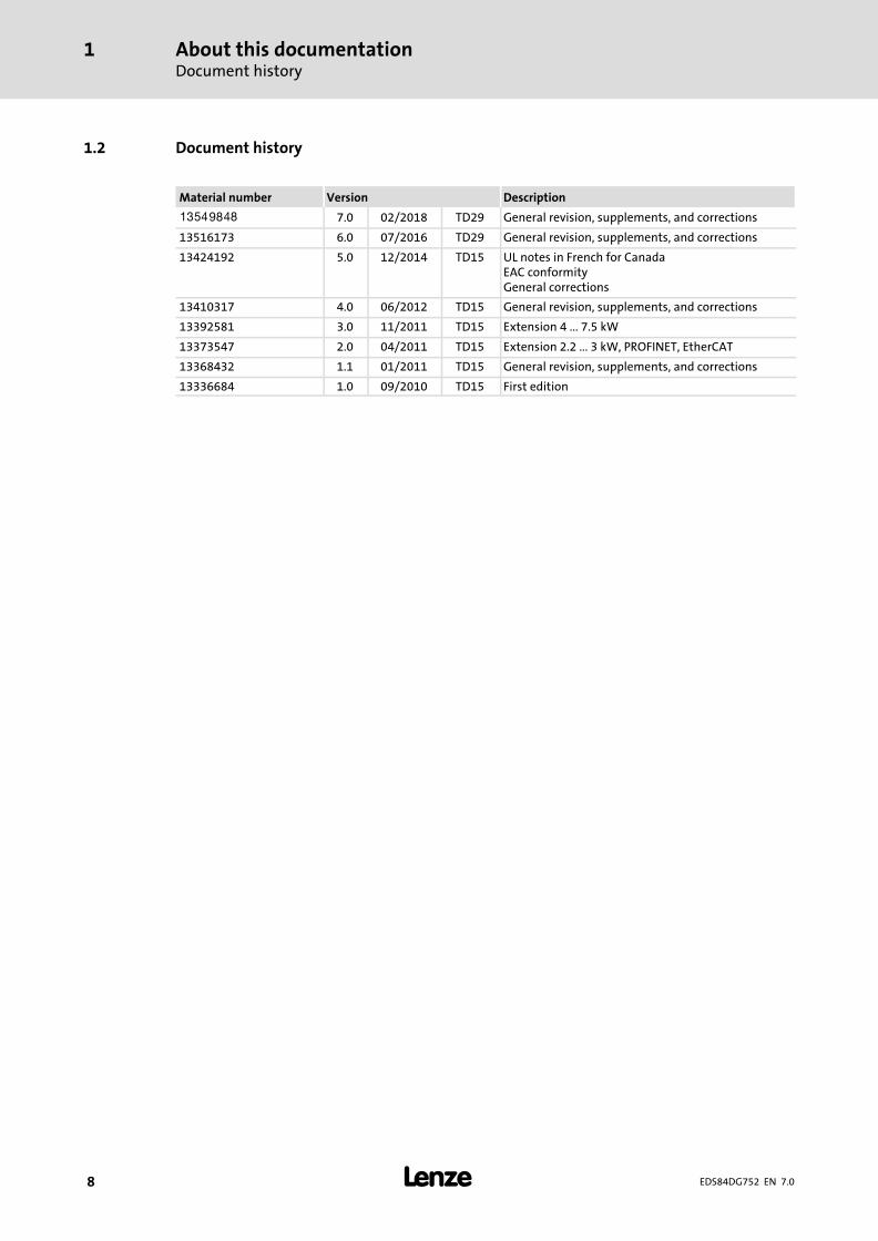
1.2 Document history
Material number Version Description
.W÷Q 7.0 02/2018 TD29 General revision, supplements, and corrections
13516173 6.0 07/2016 TD29 General revision, supplements, and corrections
13424192 5.0 12/2014 TD15 UL notes in French for CanadaEAC conformityGeneral corrections
13410317 4.0 06/2012 TD15 General revision, supplements, and corrections
13392581 3.0 11/2011 TD15 Extension 4 ... 7.5 kW
13373547 2.0 04/2011 TD15 Extension 2.2 ... 3 kW, PROFINET, EtherCAT
13368432 1.1 01/2011 TD15 General revision, supplements, and corrections
13336684 1.0 09/2010 TD15 First edition
About this documentationConventions used
1
� 9EDS84DG752 EN 7.0
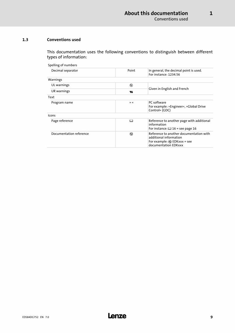
1.3 Conventions used
This documentation uses the following conventions to distinguish between differenttypes of information:
Spelling of numbers
Decimal separator Point In general, the decimal point is used.For instance: 1234.56
Warnings
UL warnings �Given in English and French
UR warnings �Text
Program name » « PC softwareFor example: »Engineer«, »Global DriveControl« (GDC)
Icons
Page reference � Reference to another page with additionalinformationFor instance: � 16 = see page 16
Documentation reference � Reference to another documentation withadditional informationFor example: � EDKxxx = seedocumentation EDKxxx

About this documentationTerms and abbreviations used
1
� 10 EDS84DG752 EN 7.0
1.4 Terms and abbreviations used
Term Meaning
Device size Used as generic term for a group of devices which have the same dimensions(depth, height and width) but different power ratings.
Standard device Used as generic term when actions and features are described which are verysimilar or the same for different versions or device sizes, e.g.� mechanical installation or� power terminals
DU Drive unit8400 motec controller
CU Communication unitOptional interfaces per I/O, fieldbus, safety system
WU Wiring unitReady−made motor connection, replaces the motor terminal box
Abbreviation Meaning
24O 24 V voltage supply for non−safe monitoring
Cat. Category according to EN 954−1 (valid until 30 November 2009)
DO Non−safe feedback output
F−PLC Safety PLC
GSDML File containing device−specific data to establish PROFINET communication
GSE File containing device−specific data to establish PROFIBUS communication
OFF state Signal status of the safety sensors when they are activated or respond
ON state Signal status of the safety sensors during normal operation
Opto supply Optocoupler supply for controlling the drivers
OSSD Output Signal Switching Device, tested signal output
PELV Protective Extra Low Voltage
PL Performance Level according to EN ISO 13849−1
PM P/N switching signal paths
PP P/P switching signal paths
PS PROFIsafe
PWM Pulse Width Modulation
S−Bus Safety bus
SD−In Safe input (Safe Digital Input)
SD−Out Safe output (Safe Digital Output)
SELV Safety Extra Low Voltage
SIA, SIB Safe Input, channel A or B, respectively
SIL Safety Integrity Level according to IEC 61508
SO Integrated safety option
n.�c. Terminal not assigned
Abbreviation Safety function
STO Safe Torque OffFormer designation: safe standstill
About this documentationNotes used
1
� 11EDS84DG752 EN 7.0
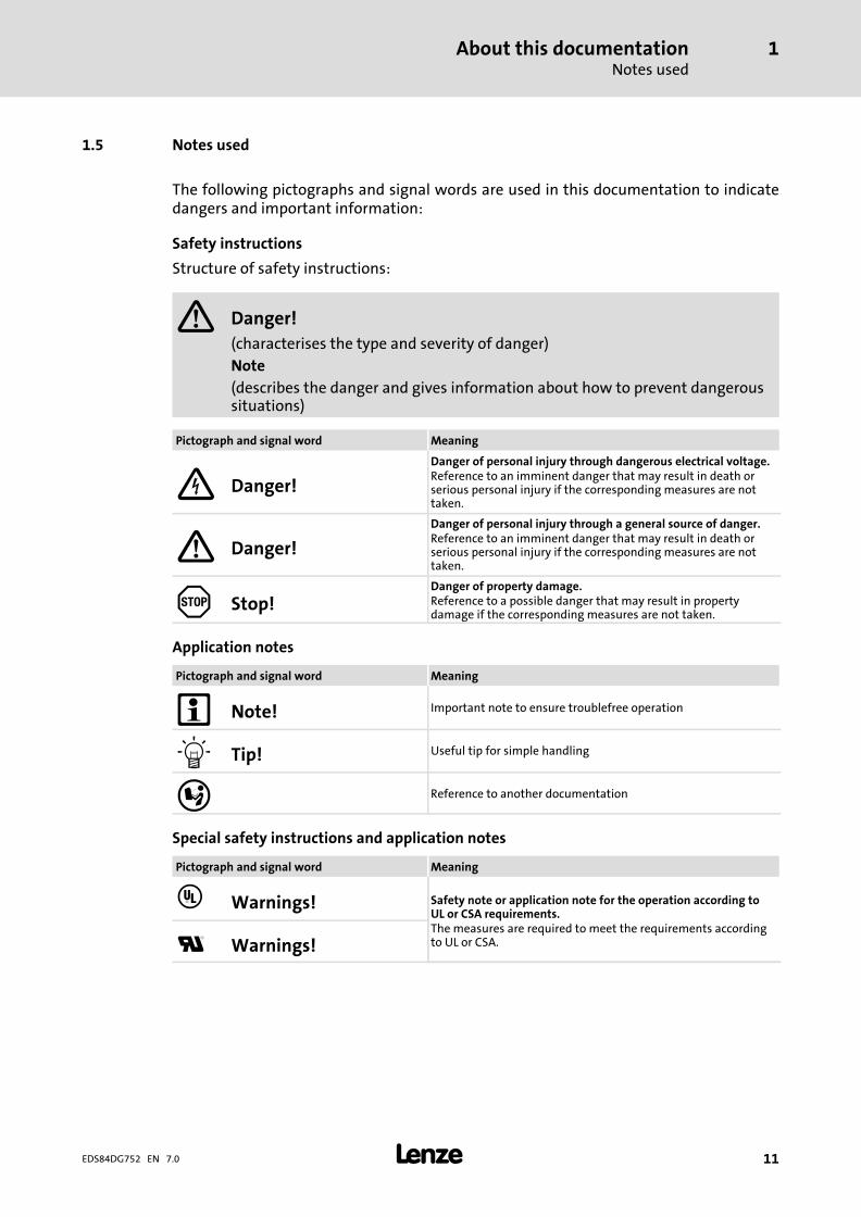
1.5 Notes used
The following pictographs and signal words are used in this documentation to indicatedangers and important information:
Safety instructions
Structure of safety instructions:
� Danger!
(characterises the type and severity of danger)Note
(describes the danger and gives information about how to prevent dangeroussituations)
Pictograph and signal word Meaning
Danger!
Danger of personal injury through dangerous electrical voltage.Reference to an imminent danger that may result in death orserious personal injury if the corresponding measures are nottaken.
� Danger!
Danger of personal injury through a general source of danger.Reference to an imminent danger that may result in death orserious personal injury if the corresponding measures are nottaken.
Stop!Danger of property damage.Reference to a possible danger that may result in propertydamage if the corresponding measures are not taken.
Application notes
Pictograph and signal word Meaning
� Note! Important note to ensure troublefree operation
� Tip! Useful tip for simple handling
� Reference to another documentation
Special safety instructions and application notes
Pictograph and signal word Meaning
� Warnings! Safety note or application note for the operation according toUL or CSA requirements.The measures are required to meet the requirements accordingto UL or CSA.� Warnings!
Safety instructionsGeneral safety and application notes for Lenze controllers
2
� 12 EDS84DG752 EN 7.0
2 Safety instructions
2.1 General safety and application notes for Lenze controllers
(in accordance with Low−Voltage Directive 2014/35/EU)
For your personal safety
Disregarding the following basic safety measures may lead to severe personal injury anddamage to material assets:
ƒ Use the product as intended.
ƒ Never operate the product if damages are visible.
ƒ Never operate the product unless fully assembled.
ƒ Do not make any technical changes to the product.
ƒ Only use the accessories approved for the product.
ƒ Only use original spare parts of the manufacturer.
ƒ Observe all regulations for the prevention of accidents, directives and lawsapplicable on site.
ƒ Transport, installation, commissioning and maintenance work must only be carriedout by qualified personnel.
– Observe IEC 364 and CENELEC HD 384 or DIN VDE 0100 and IEC report 664 or DINVDE 0110 and all national regulations for the prevention of accidents.
– According to the basic safety information, qualified, skilled personnel are personswho are familiar with the assembly, installation, commissioning, and operation ofthe product and who have the qualifications necessary for their occupation.
ƒ Observe all specifications in this documentation.
– This is the condition for safe and troublefree operation and the achievement of thespecified product features.
– The procedural notes and circuit details described in this documentation are onlyproposals. It is up to the user to check whether they can be transferred to theparticular applications. Lenze Drives GmbH does not accept any liability for thesuitability of the procedures and circuit proposals described.
ƒ Lenze inverters (frequency inverters, servo inverters, DC speed controllers) and theaccessory components can include live and moving parts (depending ontheir type ofprotection) during operation. Surfaces can be hot.
– Nonauthorized removal of the required cover, inappropriate use, incorrectinstallation or operation create the risk of severe injury to persons or damage tomaterial assets.
– For more information, please see the documentation.
ƒ High amounts of energy are produced in the drive. Therefore it is required to wearpersonal protective equipment (body protection, headgear, eye and ear protection,hand guard).
Safety instructionsGeneral safety and application notes for Lenze controllers
2
� 13EDS84DG752 EN 7.0
Application as directed
Inverters are components which are designed for installation in electrical systems ormachines. They are not to be used as domestic appliances, but only for industrial purposesaccording to EN 6100032.When inverters are installed into machines, commissioning (i.e. starting of the operationas directed) is prohibited until it is proven that the machine complies with the regulationsof the EC Directive 2006/42/EC (Machinery Directive); EN 60204 must be observed.Commissioning (i.e. starting of the operation as directed) is only allowed when there iscompliance with the EMC Directive (2014/30/EU).The inverters meet the requirements of the Low−Voltage Directive 2006/35/EU. Theharmonised standard EN 61800−5−1 applies to the inverters.The technical data and supply conditions can be obtained from the nameplate and thedocumentation. They must be strictly observed.Warning: Inverters are products which can be installed in drive systems of category C2according to EN 61800−3. These products can cause radio interferences in residential areas.In this case, special measures can be necessary.
Transport, storage
Observe the notes on transport, storage, and appropriate handling.Observe the climatic conditions according to the technical data.
Installation
The inverters must be installed and cooled according to the instructions given in thecorresponding documentation.The ambient air must not exceed degree of pollution 2 according to EN 61800−5−1.Ensure proper handling and avoid excessive mechanical stress. Do not bend anycomponents and do not change any insulation distances during transport or handling.Donot touch any electronic components and contacts.Inverters contain electrostatic sensitive devices which can easily be damaged byinappropriate handling. Do not damage or destroy any electrical components sincethismight endanger your health!
Electrical connection
When working on live inverters, observe the applicable national regulations for theprevention of accidents.The electrical installation must be carried out according to the appropriate regulations(e.g. cable cross−sections, fuses, PE connection). Additional information can be obtainedfrom the documentation.This documentation contains information on installation in compliance with EMC(shielding, earthing, filter, and cables). These notes must also be observed forCE−markedinverters. The manufacturer of the system is responsible for compliance withthe limit values demanded by EMC legislation.Lenze inverters may cause a DC current in the PE conductor. If a residual current device(RCD) is used for protection against direct or indirect contact for an inverterwiththree−phase supply, only a residual current device (RCD) of type B is permissible on thesupply side of the inverter. If the inverter has a single−phase supply, a residual currentdevice (RCD) of type A is also permissible. Apart from using a residual current device (RCD),other protective measures can be taken as well, e.g. electrical isolation by double orreinforced insulation or isolation from the supply system by means of a transformer.

Safety instructionsGeneral safety and application notes for Lenze controllers
2
� 14 EDS84DG752 EN 7.0
Operation
If necessary, systems including inverters must be equipped with additional monitoringand protection devices according to the valid safety regulations (e.g. law on technicalequipment, regulations for the prevention of accidents). The inverters can be adapted toyour application. Please observe the corresponding information given in thedocumentation.After the inverter has been disconnected from the supply voltage, all live components andpower terminals must not be touched immediately because capacitors can still be charged.Please observe the corresponding stickers on the inverter.All protection covers and doors must be shut during operation.Note for UL−approved systems with installed inverters: UL warnings are notes that onlyapply to UL systems. The documentation contains special UL notes.
Safety functions
Certain inverter versions support safety functions (e.g. "Safe torque off", formerly "Safestandstill") according to the requirements of the EC Directive 2006/42/EC (MachineryDirective). The notes on the integrated safety system provided in this documentation mustbe observed.
Maintenance and servicing
The inverters do not require any maintenance if the prescribed operating conditions areobserved.
Disposal
Recycle metal and plastic materials. Ensure professional disposal of assembled PCBs.The product−specific safety and application notes given in these instructions must beobserved!

Safety instructionsGeneral safety and application notes for Lenze motors
2
� 15EDS84DG752 EN 7.0
2.2 General safety and application notes for Lenze motors
(according to Low−Voltage Directive 2014/35/EU)
General
Low−voltage machines have dangerous, live and rotating parts as well as possibly hotsurfaces.
Synchronous machines induce voltages at open terminals during operation.
All operations serving transport, connection, commissioning and maintenance are to becarried out by skilled, responsible technical personnel (observe EN 50110−1 (VDE 0105−1)and IEC 60364). Improper handling can cause severe injuries or damages.
Lowvoltage machines may only be operated under the conditions that are indicated in thesection "Application as directed".
The conditions at the place of installation must comply with the data given on thenameplate and in the documentation.
Application as directed
Lowvoltage machines are intended for commercial installations. They comply with theharmonised standards of the series IEC/EN�60034 (VDE 0530). Their use in potentiallyexplosive atmospheres is prohibited unless they are expressly intended for such use(follow additional instructions).
Lowvoltage machines are components for installation into machines as defined in theMachinery Directive 2006/42/EC. Commissioning is prohibited until the conformity of theend product with this directive has been established (follow i. a. EN 60204−1).
Lowvoltage machines with IP23 protection or less are only intended for outdoor use whenapplying special protective features.
The integrated brakes must not be used as safety brakes. It cannot be ruled out that factorswhich cannot be influenced, such as oil ingress due to a defective Aside shaft seal, causea brake torque reduction.
Transport, storage
Damages must be reported immediately upon receipt to the forwarder; if required,commissioning must be excluded. Tighten screwedin ring bolts before transport. They aredesigned for the weight of the lowvoltage machines, do not apply extra loads. If necessary,use suitable and adequately dimensioned means of transport (e. g. rope guides).
Remove transport locking devices before commissioning. Reuse them for furthertransport. When storing low−voltage machines, ensure a dry, dustfree and low−vibration(veff � 0.2 mm/s) environment (bearing damage while being stored).

Safety instructionsGeneral safety and application notes for Lenze motors
2
� 16 EDS84DG752 EN 7.0
Installation
Ensure an even surface, solid foot/flange mounting and exact alignment if a direct clutchis connected. Avoid resonances with the rotational frequency and double mains frequencywhich may be caused by the assembly. Turn rotor by hand, listen for unusual slippingnoises. Check the direction of rotation when the clutch is not active (observe section"Electrical connection").
Use appropriate means to mount or remove belt pulleys and clutches (heating) and coverthem with a touch guard. Avoid impermissible belt tensions.
The machines are halfkey balanced. The clutch must be halfkey balanced, too. The visiblejutting out part of the key must be removed.
If required, provide pipe connections. Designs with shaft end at bottom must be protectedwith a cover which prevents the ingress of foreign particles into the fan. Free circulation ofthe cooling air must be ensured. The exhaust air also the exhaust air of other machinesnext to the drive system must not be taken in immediately.
Electrical connection
All operations must only be carried out by qualified and skilled personnel on thelowvoltage machine at standstill and deenergised and provided with a safe guard toprevent an unintentional restart.This also applies to auxiliary circuits (e. g. brake, encoder,blower).
Check safe isolation from supply!
If the tolerances specified in EN 600341; IEC 34 (VDE 05301) voltage ±5 %, frequency ±2 %,waveform, symmetry are exceeded, more heat will be generated and the electromagneticcompatibility will be affected.
Observe the data on the nameplate, operating notes, and the connection diagram in theterminal box.
The connection must ensure a continuous and safe electrical supply (no loose wire ends);use appropriate cable terminals. The connection to the PE conductor must be safe. Theplug−in connectors must be bolt tightly (tostop).
The clearances between blank, live parts and to earth must not fall below 8 mm atVrated � 550 V, 10 mm at Vrated � 725 V, 14 mm at Vrated � 1000 V.
The terminal box must be free of foreign particles, dirt and moisture. All unused cableentries and the box itself must be sealed against dust and water.
Safety instructionsGeneral safety and application notes for Lenze motors
2
� 17EDS84DG752 EN 7.0
Commissioning and operation
Before commissioning after longer storage periods, measure insulation resistance. In caseof values � 1 k� per volt of rated voltage, dry winding.
For trial run without output elements, lock the featherkey. Do not deactivate theprotective devices, not even in a trial run.
Check the correct operation of the brake before commissioning lowvoltage machines withbrakes.
Integrated thermal detectors do not provide full protection for the machine. If necessary,limit the maximum current. Parameterise the controller so that the motor will be switchedoff with I > Irated after a few seconds of operation, especially at the risk of blocking.
Vibrational severities veff � 3.5 mm/s (Prated � 15 kW) or 4.5 mm/s (Prated > 15 kW) areacceptable if the clutch is activated.
If deviations from normal operation occur, e.g. increased temperatures, noises, vibrations,find the cause and, if required, contact the manufacturer. In case of doubt, switch off thelowvoltage machine.
If the machine is exposed to dirt, clean the air paths regularly.
Shaft sealing rings and roller bearings have a limited service life.
Regrease bearings with relubricating devices while the lowvoltage machine is running.Only use the grease recommended by the manufacturer. If the grease drain holes aresealed with a plug, (IP54 drive end; IP23 drive and nondrive end), remove plug beforecommissioning. Seal bore holes with grease. Replace prelubricated bearings (2Z bearing)after approx. 10,000 h 20,000 h, at the latest however after 3 4 years.
The product−specific safety and application notes given in these instructions must beobserved!!
Safety instructionsResidual hazards
2
� 18 EDS84DG752 EN 7.0
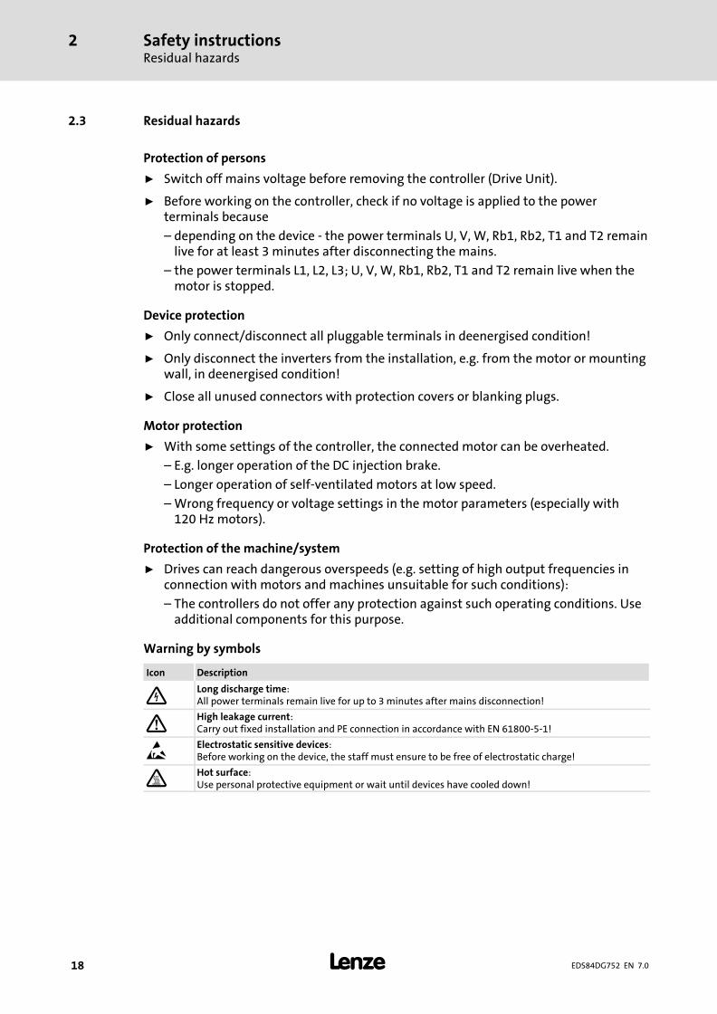
2.3 Residual hazards
Protection of persons
ƒ Switch off mains voltage before removing the controller (Drive Unit).
ƒ Before working on the controller, check if no voltage is applied to the powerterminals because
– depending on the device − the power terminals U, V, W, Rb1, Rb2, T1 and T2 remainlive for at least 3 minutes after disconnecting the mains.
– the power terminals L1, L2, L3; U, V, W, Rb1, Rb2, T1 and T2 remain live when themotor is stopped.
Device protection
ƒ Only connect/disconnect all pluggable terminals in deenergised condition!
ƒ Only disconnect the inverters from the installation, e.g. from the motor or mountingwall, in deenergised condition!
ƒ Close all unused connectors with protection covers or blanking plugs.
Motor protection
ƒ With some settings of the controller, the connected motor can be overheated.
– E.g. longer operation of the DC injection brake.
– Longer operation of self−ventilated motors at low speed.
– Wrong frequency or voltage settings in the motor parameters (especially with120 Hz motors).
Protection of the machine/system
ƒ Drives can reach dangerous overspeeds (e.g. setting of high output frequencies inconnection with motors and machines unsuitable for such conditions):
– The controllers do not offer any protection against such operating conditions. Useadditional components for this purpose.
Warning by symbols
Icon Description
Long discharge time:All power terminals remain live for up to 3 minutes after mains disconnection!
� High leakage current:Carry out fixed installation and PE connection in accordance with EN 61800−5−1!
� Electrostatic sensitive devices:Before working on the device, the staff must ensure to be free of electrostatic charge!
Hot surface:Use personal protective equipment or wait until devices have cooled down!

Product descriptionSystem overview
3
� 19EDS84DG752 EN 7.0
3 Product description
3.1 System overview
E84DG122
� 8400 motec 0.37�...�3.0�kW� 8400 motec 4.0�...�7.5�kW� 8400 motec Field Package without switch 0.37�...�3.0�kW� 8400 motec Field Package with switch 0.37�...�3.0�kW� 8400 motec Field Package without switch 4.0�...�7.5�kW

Product descriptionDevice features
3
� 20 EDS84DG752 EN 7.0
3.2 Device features
ƒ Compact motor inverter
ƒ Modular design
ƒ Part of the Inverter Drives 8400 product family
– Identical product features
– Identical operation
ƒ Scalable fieldbus communication (optional)
ƒ On site diagnostics per status LEDs
ƒ Extensive accessories (optional)
ƒ Pluggable memory module
ƒ Quick commissioning via DIP switches
General features
Product descriptionDevice features
3
� 21EDS84DG752 EN 7.0
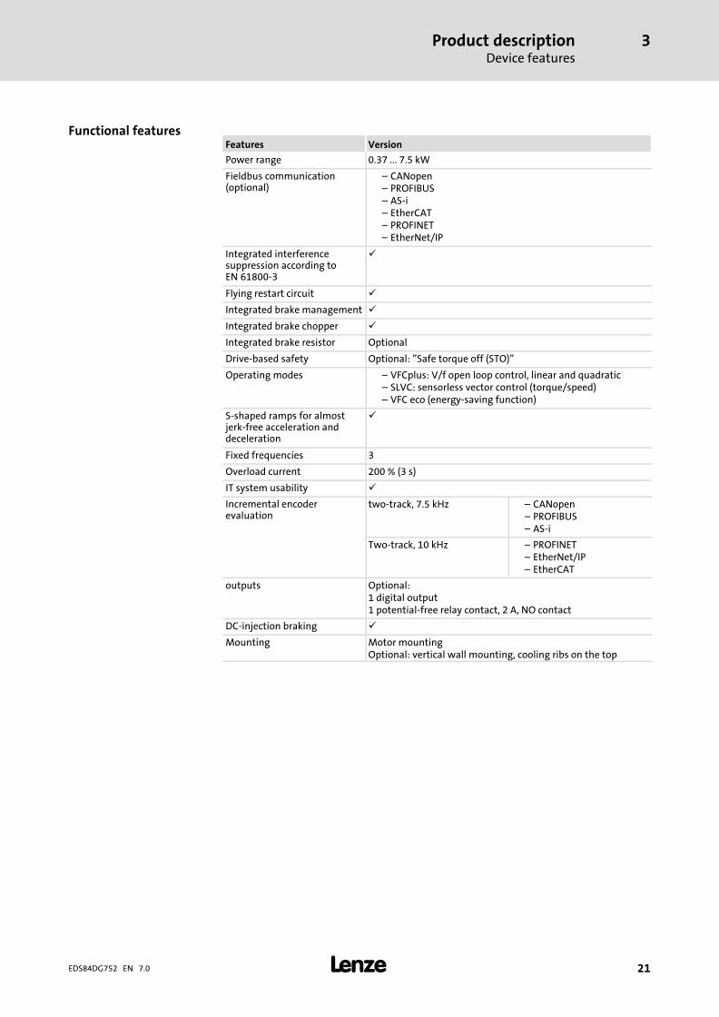
Features Version
Power range 0.37 ... 7.5 kW
Fieldbus communication(optional)
– CANopen– PROFIBUS– AS−i– EtherCAT– PROFINET– EtherNet/IP
Integrated interferencesuppression according toEN 61800−3
�
Flying restart circuit �
Integrated brake management �
Integrated brake chopper �
Integrated brake resistor Optional
Drive−based safety Optional: "Safe torque off (STO)"
Operating modes – VFCplus: V/f open loop control, linear and quadratic– SLVC: sensorless vector control (torque/speed)– VFC eco (energy−saving function)
S−shaped ramps for almostjerk−free acceleration anddeceleration
�
Fixed frequencies 3
Overload current 200 % (3 s)
IT system usability �
Incremental encoderevaluation
two−track, 7.5 kHz – CANopen– PROFIBUS– AS−i
Two−track, 10 kHz – PROFINET– EtherNet/IP– EtherCAT
outputs Optional:1 digital output1 potential−free relay contact, 2 A, NO contact
DC−injection braking �
Mounting Motor mountingOptional: vertical wall mounting, cooling ribs on the top
Functional features

Product descriptionIdentification
3
� 22 EDS84DG752 EN 7.0
3.3 Identification
Due to the modular design of the 8400 motec controllers, every unit has an ownnameplate.
The nameplate shows the type designation of the respective unit. The type designationserves to exactly identify a unit.
�180s
�
E84DGAK001
� Type designation
Note
Via the type designation, detailed device properties can be identified using the followingtype code. The list containing the type code, features, and device properties does not takeany restrictions with regard to possible combinations into consideration.
Product descriptionProduct keyWiring Unit
3
� 23EDS84DG752 EN 7.0
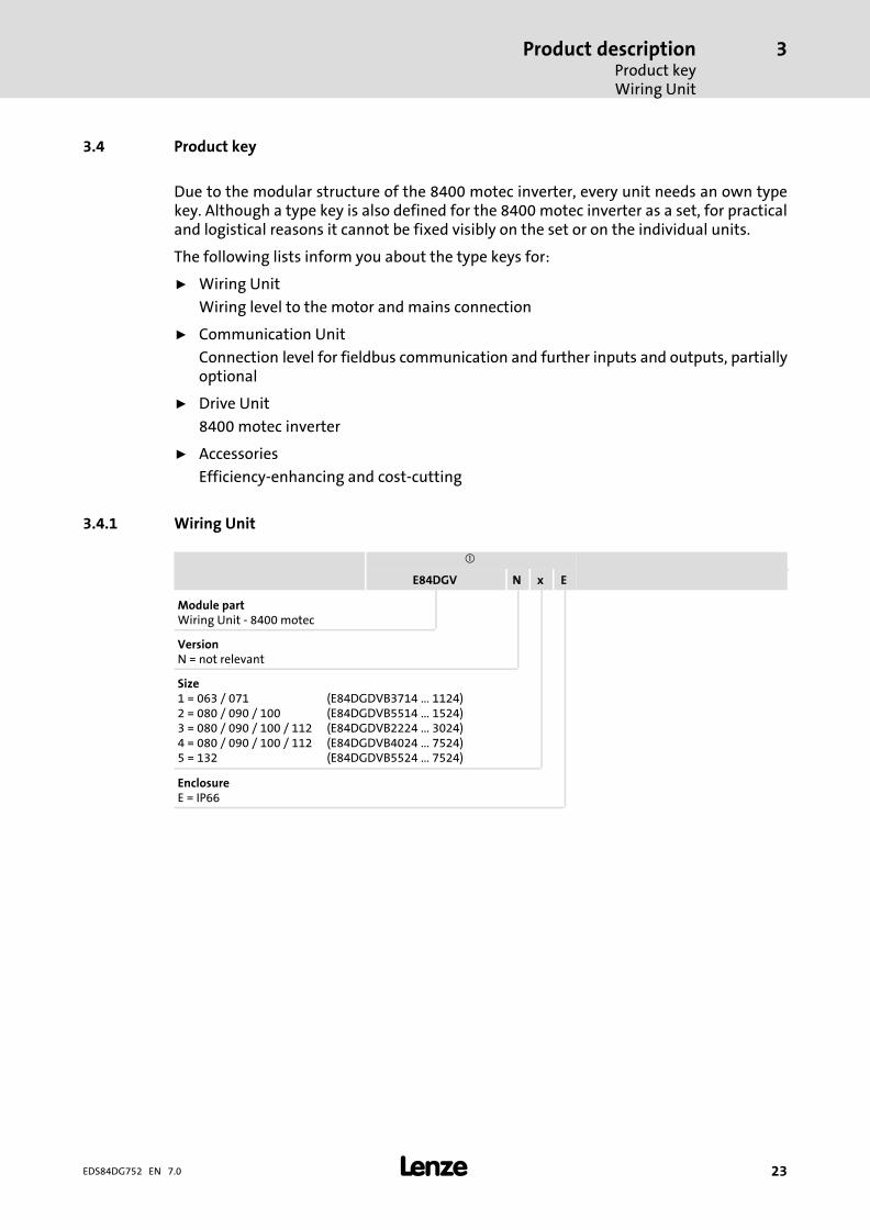
3.4 Product key
Due to the modular structure of the 8400 motec inverter, every unit needs an own typekey. Although a type key is also defined for the 8400 motec inverter as a set, for practicaland logistical reasons it cannot be fixed visibly on the set or on the individual units.
The following lists inform you about the type keys for:
ƒ Wiring Unit
Wiring level to the motor and mains connection
ƒ Communication Unit
Connection level for fieldbus communication and further inputs and outputs, partiallyoptional
ƒ Drive Unit
8400 motec inverter
ƒ Accessories
Efficiency−enhancing and cost−cutting
3.4.1 Wiring Unit
�
E84DGV N x E
Module partWiring Unit − 8400 motec
VersionN = not relevant
Size1 = 063 / 071 (E84DGDVB3714 ... 1124)2 = 080 / 090 / 100 (E84DGDVB5514 ... 1524)3 = 080 / 090 / 100 / 112 (E84DGDVB2224 ... 3024)4 = 080 / 090 / 100 / 112 (E84DGDVB4024 ... 7524)5 = 132 (E84DGDVB5524 ... 7524)
EnclosureE = IP66

Product descriptionProduct keyFrame Unit
3
� 24 EDS84DG752 EN 7.0
3.4.2 Frame Unit
�
E84DGS x x x x x N x
Module partFrame Unit 8400 motec
Design2 = without switch3 = with switch
Type of mains connectionE = cable glandK = 2 × Q4/2, loop throughL = cable gland, loop throughS = Quickon
Type of motor connectionC = Q8/0E = cable gland
Control elementN = withoutB = service switchE = service switch with control elementsK = service switch with protective function
Brake resistorN = withoutC = 220 OhmK = 90 Ohm
FanN = without
Type of protectionD = IP54P = IP65

Product descriptionProduct key
Communication Unit
3
� 25EDS84DG752 EN 7.0
3.4.3 Communication Unit
�
E84DGFC x x x P
Module partCommunication Unit − 8400 motec
I/O modules/fieldbusN = basic�I/O (without fieldbus link)S = standard�I/O (without fieldbus link)X = extended�I/O (without fieldbus link)A = AS−InterfaceC = CANopenT = EtherCAT®G = EtherNet/IPP = PROFIBUSR = PROFINET
Connection system I/O modules/fieldbusN = basic�I/O, standard�I/O, extended�I/O: terminalE = M12: bus, 3 x DI, 1 x DO (integrated safety: N)E = STO, M12: bus, 2 x DI, 1 x DO, AI, NO, STO (integrated safety: J)F = M12: bus, 2 x DI
Drive−based safetyN = noneJ = STO (safe torque off)
Type of protectionP = IP65
3.4.4 Drive Unit
�
E84DGDV B xxx 4 2 P x
Module partDrive Unit − 8400 motec
VersionB = not relevant
Power e.g.152 = 15 x 102 W = 1.5 kW
Voltage class4 = 400/480 V, 3/PE AC (also for IT systems)
Memory module2 = standard 8400 motec
Type of protectionP = IP65
Control elementS = standard (DIP switches/potentiometer/X70)P = version P1 (only potentiometer P1)

Product descriptionProduct key8400 motec Set
3
� 26 EDS84DG752 EN 7.0
3.4.5 8400 motec Set
�
E84DV B x xxx 4 S x x x 2 P x
Product seriesInverter Drives 8400 motec
VersionB = not relevant
DesignM = motor−mounted deviceW = wall−mounted device
Power e.g.152 = 15 x 102 W = 1.5 kW
Voltage class4 = 400/480 V, 3/PE AC (also for IT systems)
Control elementS = standard (DIP switches/potentiometer/X70)
I/O modules / fieldbusN = basic�I/O (without fieldbus)S = standard I/O (without fieldbus)X = extended I/O (without fieldbus)A = AS−InterfaceC = CANopenT = EtherCAT®G = EtherNet/IPP = PROFIBUSR = PROFINET
Connection system I/O modules / fieldbusN = basic�I/O, standard�I/O, extended�I/O: terminalE = M12: bus, 3 x DI, 1 x DO (integrated safety: N)E = STO, M12: bus, 2 x DI, 1 x DO, AI, NO, STO (integrated safety: J)F = M12: bus, 2 x DI
Drive−based safetyN = noneJ = STO (safe torque off)
Memory module2 = for motec
Type of protectionP = IP65
Size1 = 063 / 071 (E84DGDVB3714 ... 1124)2 = 080 / 090 / 100 (E84DGDVB5514 ... 1524)3 = 080 / 090 / 100 / 112 (E84DGDVB2224 ... 3024)4 = 080 / 090 / 100 / 112 (E84DGDVB4024 ... 7524)5 = 132 (E84DGDVB5524 ... 7524)

Product descriptionProduct key
Field Package without switch
3
� 27EDS84DG752 EN 7.0
3.4.6 Field Package without switch
�
Z2 5 x x 0 x x x x x x F
Product variantField Package without switch − 8400 motec
Version5 = not relevant
Connection technique for power terminalA = cable glandB = 2 x Q4/2, Q8/0C = Quickon, Q8/0
Connection technique for DC 24 V0 = withoutA = cable glandB = Q4/2
Brake resistor0 = withoutA = 220 Ohm integratedB = 90 Ohm integrated
Fieldbus0 = withoutA = AS−InterfaceC = CANopenT = EtherCAT®G = EtherNet/IPP = PROFIBUSR = PROFINET
I/O terminalsA = Basic�I/O (without fieldbus)B = Standard�I/O (without fieldbus) or fieldbus with STOC = fieldbus without STOD = Extended�I/O (without fieldbus)
Drive−based safety0 = without STOA = with STO
Connection technique for I/O modules/fieldbusA = withoutC = M12: LED, bus, DI1, DI2D = M12: LED, bus, DI1, DI2, DO1, NO, AI, STOE = M12: bus−in, bus−out, DI1, DI2F = M12: bus−in, bus−out, DI1, DI2 DO1, NO, AI, STOG = M12: LED, bus−in, bus−out, DI1, DI2H = M12: LED, bus−in, bus−out, DI1, DI2 DO1, NO, AI, STOI = M12: LED, bus, DI1, DI2, DI3, DO1J = M12: bus−in, bus−out, DI1, DI2, DI3, DO1K = M12: LED, bus−in, bus−out, DI1, DI2, DI3, DO1
Rated power215 = 102 × 15 W = 1.5 kW (example)
Rated voltageF = 400/480 V, 3/PE AC (also for IT systems)

Product descriptionProduct keyField Package with switch
3
� 28 EDS84DG752 EN 7.0
3.4.7 Field Package with switch
�
Z3 5 x x x x x x x x x F
Product variantField Package with switch − 8400 motec
Version5 = not relevant
Connection technique for power terminalA = cable glandB = 2 x Q4/2, Q8/0
Connection technique for DC 24 V0 = withoutA = cable glandB = Q4/2
Service switch0 = withoutA = service switchB = service switch with protective functionC = service switch with control elements
Brake resistor0 = withoutA = 220 Ohm integratedB = 90 Ohm integrated
Fieldbus0 = withoutA = AS−InterfaceC = CANopenT = EtherCAT®G = EtherNet/IPP = PROFIBUSR = PROFINET
I/O terminalsA = Basic�I/O (without fieldbus)B = Standard�I/O (without fieldbus) or fieldbus with STOC = fieldbus without STOD = Extended�I/O (without fieldbus)
Drive−based safety0 = without STOA = with STO
Connection technique for I/O modules/fieldbusA = withoutC = M12: LED, bus, DI1, DI2D = M12: LED, bus, DI1, DI2, DO1, NO, AI, STOE = M12: bus−in, bus−out, DI1, DI2F = M12: bus−in, bus−out, DI1, DI2 DO1, NO, AI, STOG = M12: LED, bus−in, bus−out, DI1, DI2H = M12: LED, bus−in, bus−out, DI1, DI2 DO1, NO, AI, STOI = M12: LED, bus, DI1, DI2, DI3, DO1J = M12: bus−in, bus−out, DI1, DI2, DI3, DO1K = M12: LED, bus−in, bus−out, DI1, DI2, DI3, DO1
Rated power215 = 102 × 15 W = 1.5 kW (example)
Rated voltageF = 3/PE AC 480 V

Product descriptionOverview of control terminals
3
� 29EDS84DG752 EN 7.0
3.5 Overview of control terminals
The control terminals of the 8400�motec inverters are always located in theCommunication Unit.
The type of fieldbus version, power class of the inverter, or motor frame size have noinfluence on the availability of the device versions.
For 8400�motec withouta fieldbus link, three types of control terminals are available:
ƒ Basic�I/O
ƒ Standard�I/O
ƒ Extended�I/O
For 8400�motec witha fieldbus link, two types of control terminals are available:
ƒ Without safety and with the I/O functions as for the standard�I/O, but without ananalog input and relay output
ƒ With safety and all I/O functions as for the standard�I/O
Connection options for Communication Unit
Plugs X3 X61 X4 X1
Name Fieldbus Safety Digital input/output Analoginput
Relay Holdingbrake
Type SIA/SIB RFR DIx DO1 AI/AU COM/NO BD1/BD2
E84DGFCNNNx Basic�I/O 1) − 1�x 2 x − − � �
E84DGFCSNNx Standard�I/O 1) − 1�x 5 x � � � �
E84DGFCXNNx Extended�I/O 1) − 1�x 8 x � 2 x � � �
E84DGFCAxNxAS interface
−
1 x 5 x �
− −
�
E84DGFCAxJx � � �
E84DGFCCxNxCANopen
− − −
E84DGFCCxJx � � �
E84DGFCGxNxEtherNet/IP
− − −
E84DGFCGxJx � � �
E84DGFCPxNxPROFIBUS
− − −
E84DGFCPxJx � � �
E84DGFCRxNxPROFINET
− − −
E84DGFCRxJx � � �
E84DGFCTxNxEtherCAT
− − −
E84DGFCTxJx � � �
� Available− Not available1) Without a fieldbus link

Technical dataGeneral data and operating conditions
4
� 30 EDS84DG752 EN 7.0
4 Technical data
4.1 General data and operating conditions
Conformity and approval
Conformity
CE 2014/35/EC LowVoltage Directive
EAC �����������
(TR CU 004/2011)On safety of low voltageequipment
Eurasian ConformityTR CU: Technical Regulation ofCustoms Union
EAC ����������
(TR CU 020/2011)Electromagneticcompatibility of technicalmeans
Eurasian ConformityTR CU: Technical Regulation ofCustoms Union
Approval
UR UL 508C Power ConversionEquipment, File No.E170350CUR C22.2 No 274−13
Field Package approval
CULUS UL 508CC22.2 No 274−13
Power ConversionEquipment, File No.E132659
Protection of persons and equipment
Enclosure � Close unused bores for cable glands with blanking plugs!� Close unused connectors with protection covers or
blanking plugs!
EN 60529 8400 motec SetField Package withoutswitch
IP65
Field Package with serviceswitch / with serviceswitch and controlelements
IP54
Field Package with serviceswitch and protectivefunction
IP64
NEMA 250 8400 motec Set Type�4X (interior)
Field Package withoutswitch
0.37�...�3.0�kW Type�12
4.0�...�7.5�kW Type�4X (interior)
Field Package with switch
0.37�...�3.0�kW Type�12
(Earth) leakage current EN 61800−5−1 > 3.5 mA AC, > 10 mA DC Observe the regulations andsafety instructions!
Total fault current In TN systems the following earth−leakage circuit breakers canbe used:
Motor mounting 0.37�...�3.0�kW 30 mA, type B
4.0�...�7.5�kW,fch�= 8/16 kHz
30 mA, type B
4.0�...�7.5�kW, fch�= 4 kHz 300 mA, type B
Wall mounting andLenze system cable��3�m
0.37�...�3.0�kW 30 mA, type B
4.0�...�7.5�kW,fch�= 8/16 kHz
30 mA, type B
Technical dataGeneral data and operating conditions
4
� 31EDS84DG752 EN 7.0
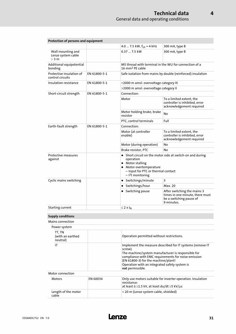
Protection of persons and equipment
4.0�...�7.5�kW, fch�= 4 kHz 300 mA, type B
Wall mounting andLenze system cable��3�m
0.37�...�7.5�kW 300 mA, type B
Additional equipotentialbonding
M5 thread with terminal in the WU for connection of a16 mm2 PE cable
Protective insulation ofcontrol circuits
EN 61800−5−1 Safe isolation from mains by double (reinforced) insulation
Insulation resistance EN 61800−5−1 <2000 m amsl: overvoltage category III
>2000 m amsl: overvoltage category II
Short−circuit strength EN 61800−5−1 Connection:
Motor To a limited extent, thecontroller is inhibited, erroracknowledgement required
Motor holding brake, brakeresistor No
PTC, control terminals Full
Earth−fault strength EN 61800−5−1 Connection:
Motor (at controllerenable)
To a limited extent, thecontroller is inhibited, erroracknowledgement required
Motor (during operation) No
Brake resistor, PTC No
Protective measuresagainst
� Short circuit on the motor side at switch−on and duringoperation
� Motor stalling� Motor overtemperature
– Input for PTC or thermal contact– I2t monitoring
Cyclic mains switching � Switchings/minute 3
� Switchings/hour Max. 20
� Switching pause After switching the mains 3times in one minute, there mustbe a switching pause of9 minutes.
Starting current � 2 x IN
Supply conditions
Mains connection
Power system
TT, TN(with an earthedneutral)
Operation permitted without restrictions.
IT Implement the measure described for IT systems (remove ITscrew).The machine/system manufacturer is responsible forcompliance with EMC requirements for noise emission(EN 61800−3) for the machine/plant!Operation with an integrated safety system isnot permissible.
Motor connection
Motors EN 60034 Only use motors suitable for inverter operation. Insulationresistance: at least û �1.5 kV, at least du/dt �5 kV/�s
Length of the motorcable
< 20 m (Lenze system cable, shielded)
Technical dataGeneral data and operating conditions
4
� 32 EDS84DG752 EN 7.0
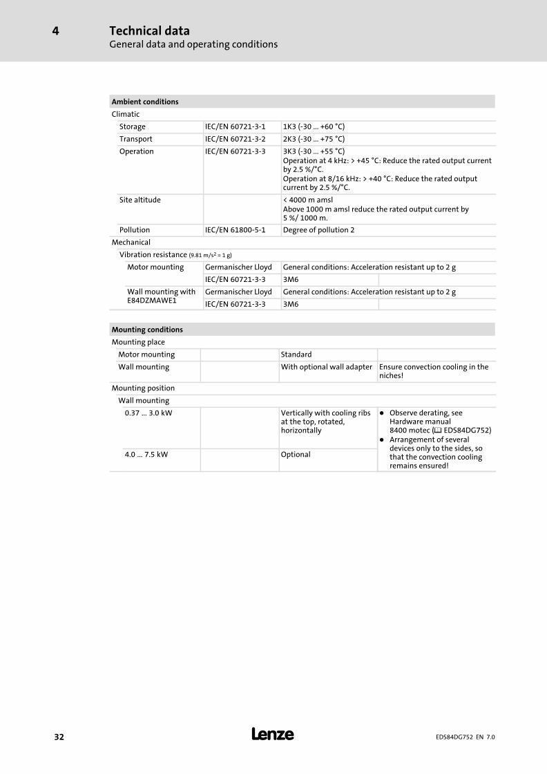
Ambient conditions
Climatic
Storage IEC/EN 60721−3−1 1K3 (−30 ... +60 °C)
Transport IEC/EN 60721−3−2 2K3 (−30 ... +75 °C)
Operation IEC/EN 60721−3−3 3K3 (−30 ... +55 °C)Operation at 4 kHz: > +45 °C: Reduce the rated output currentby 2.5 %/°C.Operation at 8/16 kHz: > +40 °C: Reduce the rated outputcurrent by 2.5 %/°C.
Site altitude < 4000 m amslAbove 1000 m amsl reduce the rated output current by5 %/ 1000 m.
Pollution IEC/EN 61800−5−1 Degree of pollution 2
Mechanical
Vibration resistance (9.81 m/s2 = 1 g)
Motor mounting Germanischer Lloyd General conditions: Acceleration resistant up to 2 g
IEC/EN 60721−3−3 3M6
Wall mounting withE84DZMAWE1
Germanischer Lloyd General conditions: Acceleration resistant up to 2 g
IEC/EN 60721−3−3 3M6
Mounting conditions
Mounting place
Motor mounting Standard
Wall mounting With optional wall adapter Ensure convection cooling in theniches!
Mounting position
Wall mounting
0.37�...�3.0�kW Vertically with cooling ribsat the top, rotated,horizontally
� Observe derating, seeHardware manual8400 motec (� EDS84DG752)
� Arrangement of severaldevices only to the sides, sothat the convection coolingremains ensured!
4.0�...�7.5�kW Optional
Technical dataGeneral data and operating conditions
4
� 33EDS84DG752 EN 7.0
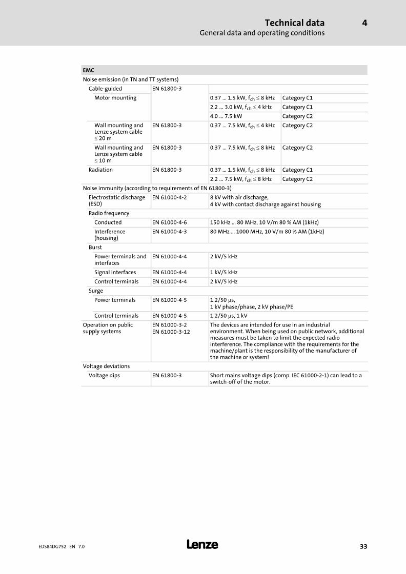
EMC
Noise emission (in TN and TT systems)
Cable−guided EN 61800−3
Motor mounting 0.37�...�1.5�kW, fch���8 kHz Category C1
2.2�...�3.0�kW, fch���4 kHz Category C1
4.0�...�7.5�kW Category C2
Wall mounting andLenze system cable� 20 m
EN 61800−3 0.37�...�7.5�kW, fch���4 kHz Category C2
Wall mounting andLenze system cable� 10 m
EN 61800−3 0.37�...�7.5�kW, fch���8 kHz Category C2
Radiation EN 61800−3 0.37�...�1.5�kW, fch���8 kHz Category C1
2.2�...�7.5�kW, fch���8 kHz Category C2
Noise immunity (according to requirements of EN 61800−3)
Electrostatic discharge(ESD)
EN 61000−4−2 8 kV with air discharge,4 kV with contact discharge against housing
Radio frequency
Conducted EN 61000−4−6 150 kHz ... 80 MHz, 10 V/m 80 % AM (1kHz)
Interference(housing)
EN 61000−4−3 80 MHz ... 1000 MHz, 10 V/m 80 % AM (1kHz)
Burst
Power terminals andinterfaces
EN 61000−4−4 2 kV/5 kHz
Signal interfaces EN 61000−4−4 1 kV/5 kHz
Control terminals EN 61000−4−4 2 kV/5 kHz
Surge
Power terminals EN 61000−4−5 1.2/50 �s,1 kV phase/phase, 2 kV phase/PE
Control terminals EN 61000−4−5 1.2/50 �s, 1 kV
Operation on publicsupply systems
EN 61000−3−2EN 61000−3−12
The devices are intended for use in an industrialenvironment. When being used on public network, additionalmeasures must be taken to limit the expected radiointerference. The compliance with the requirements for themachine/plant is the responsibility of the manufacturer ofthe machine or system!
Voltage deviations
Voltage dips EN 61800−3 Short mains voltage dips (comp. IEC 61000−2−1) can lead to aswitch−off of the motor.
Technical dataGeneral data and operating conditions
4
� 34 EDS84DG752 EN 7.0
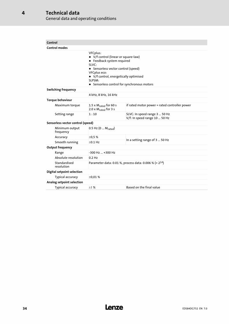
Control
Control modes
VFCplus:� V/f control (linear or square−law)� Feedback system requiredSLVC:� Sensorless vector control (speed)VFCplus eco:� V/f control, energetically optimisedSLPSM:� Sensorless control for synchronous motors
Switching frequency
4 kHz, 8 kHz, 16 kHz
Torque behaviour
Maximum torque 1.5 x Mrated for 60 s2.0 x Mrated for 3 s
if rated motor power = rated controller power
Setting range 1 : 10 SLVC: In speed range 3 ... 50 HzV/f: In speed range 10 ... 50 Hz
Sensorless vector control (speed)
Minimum outputfrequency
0.5 Hz (0 ... Mrated)
Accuracy �0,5 %In a setting range of 3 ... 50 Hz
Smooth running �0.1 Hz
Output frequency
Range −300 Hz ... +300 Hz
Absolute resolution 0.2 Hz
Standardisedresolution
Parameter data: 0.01 %, process data: 0.006 % (= 214)
Digital setpoint selection
Typical accuracy �0,01 %
Analog setpoint selection
Typical accuracy �� % Based on the final value

Technical dataRated data
Overview
4
� 35EDS84DG752 EN 7.0
4.2 Rated data
4.2.1 Overview
Input data
Mains Voltage Voltage range Frequency range
ULrated [V] ULrated [V] f [Hz]
3/PE AC 400 320 − 0 % ... 440 + 0 % 45 − 0 % ... 65 + 0 %
3/PE AC 480 432 − 0 % ... 528 + 0 % 45 − 0 % ... 65 + 0 %
Voltage Frequency Rated current [A] Number ofphases
[V] [Hz] up to +45 °C � up to +55 °C �
E84DGDVB3714 400/480 50/60 1.3/1.1 1.0/0.8 3
E84DGDVB5514 400/480 50/60 1.8/1.5 1.4/1.1 3
E84DGDVB7514 400/480 50/60 2.4/2.0 1.8/1.5 3
E84DGDVB1124 400/480 50/60 3.2/2.7 2.4/2.0 3
E84DGDVB1524 400/480 50/60 3.8/3.1 2.9/2.3 3
E84DGDVB2224 400/480 50/60 5.6/4.6 4.2/3.5 3
E84DGDVB3024 400/480 50/60 7.2/5.9 5.4/4.4 3
E84DGDVB4024 400/480 50/60 9.3/7.7 7.0/5.8 3
E84DGDVB5524 400/480 50/60 12.8/10.6 9.6/8.0 3
E84DGDVB7524 400/480 50/60 16.3/13.5 12.3/10.1 3
� Ambient temperature, switching frequency 4 kHz
Output data
Voltage Frequency Rated current [A] Number ofphases
[V] [Hz] up to +45 °C � up to +55 °C �
E84DGDVB3714 0 ... 400/480 0 ... 300 1.3/1.1 1.0/0.8 3
E84DGDVB5514 0 ... 400/480 0 ... 300 1.8/1.5 1.4/1.1 3
E84DGDVB7514 0 ... 400/480 0 ... 300 2.4/2.0 1.8/1.5 3
E84DGDVB1124 0 ... 400/480 0 ... 300 3.2/2.7 2.4/2.0 3
E84DGDVB1524 0 ... 400/480 0 ... 300 3.9/3.2 2.9/2.4 3
E84DGDVB2224 0 ... 400/480 0 ... 300 5.6/4.7 4.2/3.5 3
E84DGDVB3024 0 ... 400/480 0 ... 300 7.3/6.0 5.4/4.5 3
E84DGDVB4024 0 ... 400/480 0 ... 300 9.5/7.9 7.1/5.9 3
E84DGDVB5524 0 ... 400/480 0 ... 300 13.0/10.8 9.8/8.1 3
E84DGDVB7524 0 ... 400/480 0 ... 300 16.5/13.7 12.4/10.3 3
� Ambient temperature, switching frequency 4 kHz
� Note!
The maximally possible output voltage is approx. 94 % of the mains voltage.
� Note!
Depending on the mounting position, derating has to be taken intoconsideration with the Field Package. (� 45)

Technical dataRated dataOverview
4
� 36 EDS84DG752 EN 7.0
Power losses
Power loss PV [W]
Type when operating with rated output current Iarated when controller is inhibited
E84DGDVB3714 26 9
E84DGDVB5514 33 9
E84DGDVB7514 41 9
E84DGDVB1124 52 9
E84DGDVB1524 61 9
E84DGDVB2224 88 10
E84DGDVB3024 111 10
E84DGDVB4024 140 11
E84DGDVB5524 185 11
E84DGDVB7524 230 11

Technical dataRated data
Operation at rated mains voltage 400 V
4
� 37EDS84DG752 EN 7.0
4.2.2 Operation at rated mains voltage 400 V
Mains Voltage Voltage range Frequency range
ULrated [V] ULrated [V] f [Hz]
3/PE AC 400 320 − 0 % ... 440 + 0 % 45 − 0 % ... 65 + 0 %
Mains current Output power Motor power
at Iarated U, V, W 4 pol. ASM
Type ILrated [A] Sarated [kVA] Parated [kW]
E84DGDVB3714 1.3 0.8 0.37
E84DGDVB5514 1.8 1.1 0.55
E84DGDVB7514 2.4 1.5 0.75
E84DGDVB1124 3.2 2.0 1.1
E84DGDVB1524 3.8 2.4 1.5
E84DGDVB2224 5.6 3.4 2.2
E84DGDVB3024 7.2 4.4 3.0
E84DGDVB4024 9.3 5.7 4.0
E84DGDVB5524 12.8 7.8 5.5
E84DGDVB7524 16.3 9.9 7.5
Output currents [A] at switching frequency
2 kHz 4 kHz 8 kHz 16 kHz
Type Iarated2 IaM2 Iarated4 IaM4 Iarated8 IaM8 Iarated16 IaM16
E84DGDVB3714 − − 1.3 2.6 1.3 2.6 0.9 1.6
E84DGDVB5514 − − 1.8 3.6 1.8 3.6 1.2 2.2
E84DGDVB7514 − − 2.4 4.8 2.4 4.8 1.6 2.9
E84DGDVB1124 − − 3.2 6.4 3.2 6.4 2.1 3.8
E84DGDVB1524 − − 3.9 7.8 3.9 7.8 2.6 4.7
E84DGDVB2224 − − 5.6 11.2 5.6 11.2 3.7 6.7
E84DGDVB3024 − − 7.3 14.6 7.3 14.6 4.9 8.8
E84DGDVB4024 − − 9.5 19.0 9.5 19.0 6.3 11.4
E84DGDVB5524 − − 13.0 26.0 13.0 26.0 8.7 15.6
E84DGDVB7524 − − 16.5 33.0 16.5 33.0 11.0 19.8
IaNx Rated value of continuous output currentIaMx Maximum output current (overload current)
� Periodic load change of 3 s with IaMx and recovery time of 12 s according tothe tables under chapter � 4.4
� Can be obtained in the setting "x kHz fixed/..." in C00018Switchingfrequency
If the maximum heatsink temperature is reached, the switching frequency isreduced to 4 kHz.In the setting "x kHz var./..." in C00018 the switching frequency is reduceddepending on the output current.Depending on the switching frequency and e.g. the ambient temperature, itmay be required to reduce the output current (chapter 4.1, operatingconditions).
Technical dataRated dataOperation at rated mains voltage 400 V
4
� 38 EDS84DG752 EN 7.0
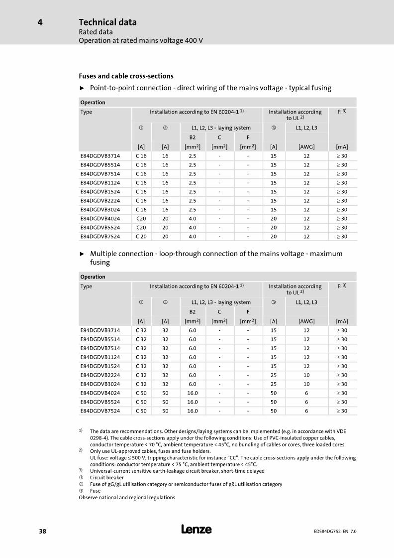
Fuses and cable cross−sections
ƒ Point−to−point connection − direct wiring of the mains voltage − typical fusing
Operation
Type Installation according to EN 60204−1 1) Installation accordingto UL 2)
FI 3)
� � L1, L2, L3 − laying system � L1, L2, L3
B2 C F
[A] [A] [mm2] [mm2] [mm2] [A] [AWG] [mA]
E84DGDVB3714 C 16 16 2.5 − − 15 12 � 30
E84DGDVB5514 C 16 16 2.5 − − 15 12 � 30
E84DGDVB7514 C 16 16 2.5 − − 15 12 � 30
E84DGDVB1124 C 16 16 2.5 − − 15 12 � 30
E84DGDVB1524 C 16 16 2.5 − − 15 12 � 30
E84DGDVB2224 C 16 16 2.5 − − 15 12 � 30
E84DGDVB3024 C 16 16 2.5 − − 15 12 � 30
E84DGDVB4024 C20 20 4.0 − − 20 12 � 30
E84DGDVB5524 C20 20 4.0 − − 20 12 � 30
E84DGDVB7524 C 20 20 4.0 − − 20 12 � 30
ƒ Multiple connection − loop−through connection of the mains voltage − maximumfusing
Operation
Type Installation according to EN 60204−1 1) Installation accordingto UL 2)
FI 3)
� � L1, L2, L3 − laying system � L1, L2, L3
B2 C F
[A] [A] [mm2] [mm2] [mm2] [A] [AWG] [mA]
E84DGDVB3714 C 32 32 6.0 − − 15 12 � 30
E84DGDVB5514 C 32 32 6.0 − − 15 12 � 30
E84DGDVB7514 C 32 32 6.0 − − 15 12 � 30
E84DGDVB1124 C 32 32 6.0 − − 15 12 � 30
E84DGDVB1524 C 32 32 6.0 − − 15 12 � 30
E84DGDVB2224 C 32 32 6.0 − − 25 10 � 30
E84DGDVB3024 C 32 32 6.0 − − 25 10 � 30
E84DGDVB4024 C 50 50 16.0 − − 50 6 � 30
E84DGDVB5524 C 50 50 16.0 − − 50 6 � 30
E84DGDVB7524 C 50 50 16.0 − − 50 6 � 30
1) The data are recommendations. Other designs/laying systems can be implemented (e.g. in accordance with VDE0298−4). The cable cross−sections apply under the following conditions: Use of PVC−insulated copper cables,conductor temperature < 70 °C, ambient temperature < 45°C, no bundling of cables or cores, three loaded cores.
2) Only use UL−approved cables, fuses and fuse holders.UL fuse: voltage � 500 V, tripping characteristic for instance "CC". The cable cross−sections apply under the followingconditions: conductor temperature < 75 °C, ambient temperature < 45°C.
3) Universal−current sensitive earth−leakage circuit breaker, short−time delayed� Circuit breaker� Fuse of gG/gL utilisation category or semiconductor fuses of gRL utilisation category� FuseObserve national and regional regulations

Technical dataRated data
Operation with increased power at a 400 V mains
4
� 39EDS84DG752 EN 7.0
4.2.3 Operation with increased power at a 400 V mains
In continuous operation, the controllers can be actuated with a more powerful motor. Theoverload capacity is limited to 120 %. Typical applications are pumps with a quadratic loadcharacteristic, or fans.
� Note!
Operation with an increased rated power is only permitted ...ƒ with the rated data specified for the controller.
ƒ within the mains voltage range specified.
ƒ with the switching frequency 4 kHz.
ƒ at a max. ambient temperature of 40 °C
ƒ with the fuses and cable cross−sections specified for this operation.ƒ after parameterisation according to the specifications (cf. EDS84DM...
software manual)
Mains Voltage Voltage range Frequency range
ULrated [V] ULrated [V] f [Hz]
3/PE AC 400 320 − 0 % ... 440 + 0 % 45 − 0 % ... 65 + 0 %
Mains current Output power Motor power
at Iarated U, V, W 4 pol. ASM
Type ILrated [A] Sarated [kVA] Parated [kW]
E84DGDVB3714 1.6 1.0 0.55
E84DGDVB5514 2.2 1.3 0.75
E84DGDVB7514 3.0 1.8 1.1
E84DGDVB1124 3.8 2.4 1.5
E84DGDVB1524 1) 4.6 3.0 1.8
E84DGDVB2224 7.0 4.1 2.2
E84DGDVB3024 1) 8.6 5.3 4.0
E84DGDVB4024 11.3 6.8 5.5
E84DGDVB5524 15.3 9.4 7.5
E84DGDVB7524 2) 19.5 11.9 9.2
1) Operation with increased rated power for motor mounting only.2) Motor connection with plug (Q8) not permissible.

Technical dataRated dataOperation with increased power at a 400 V mains
4
� 40 EDS84DG752 EN 7.0
Output currents [A] at switching frequency
2 kHz 4 kHz 8 kHz 16 kHz
Type Iarated2 IaM2 Iarated4 IaM4 Iarated8 IaM8 Iarated16 IaM16
E84DGDVB3714 − − 1.6 2.6 − − − −
E84DGDVB5514 − − 2.2 3.6 − − − −
E84DGDVB7514 − − 3.0 4.8 − − − −
E84DGDVB1124 − − 3.8 6.4 − − − −
E84DGDVB1524 1) − − 4.8 7.8 − − − −
E84DGDVB2224 − − 7.0 11.2 − − − −
E84DGDVB3024 1) − − 8.7 14.6 − − − −
E84DGDVB4024 − − 11.6 19.0 − − − −
E84DGDVB5524 − − 15.6 26.0 − − − −
E84DGDVB7524 2) − − 19.8 33.0 − − − −
1) Operation with increased rated power for motor mounting only.2) Motor connection with plug (Q8) not permissible.
IaNx Rated value of continuous output currentIaMx Maximum output current (overload current)
� Periodic load change of 3 s with IaMx and recovery time of 12 s according tothe tables under chapter � 4.4
Fuses and cable cross−sections
The data/recommendations for operation on a rated mains voltage 400 V can be applied.
(� 38)
Technical dataRated data
Operation with rated mains voltage 480 V
4
� 41EDS84DG752 EN 7.0
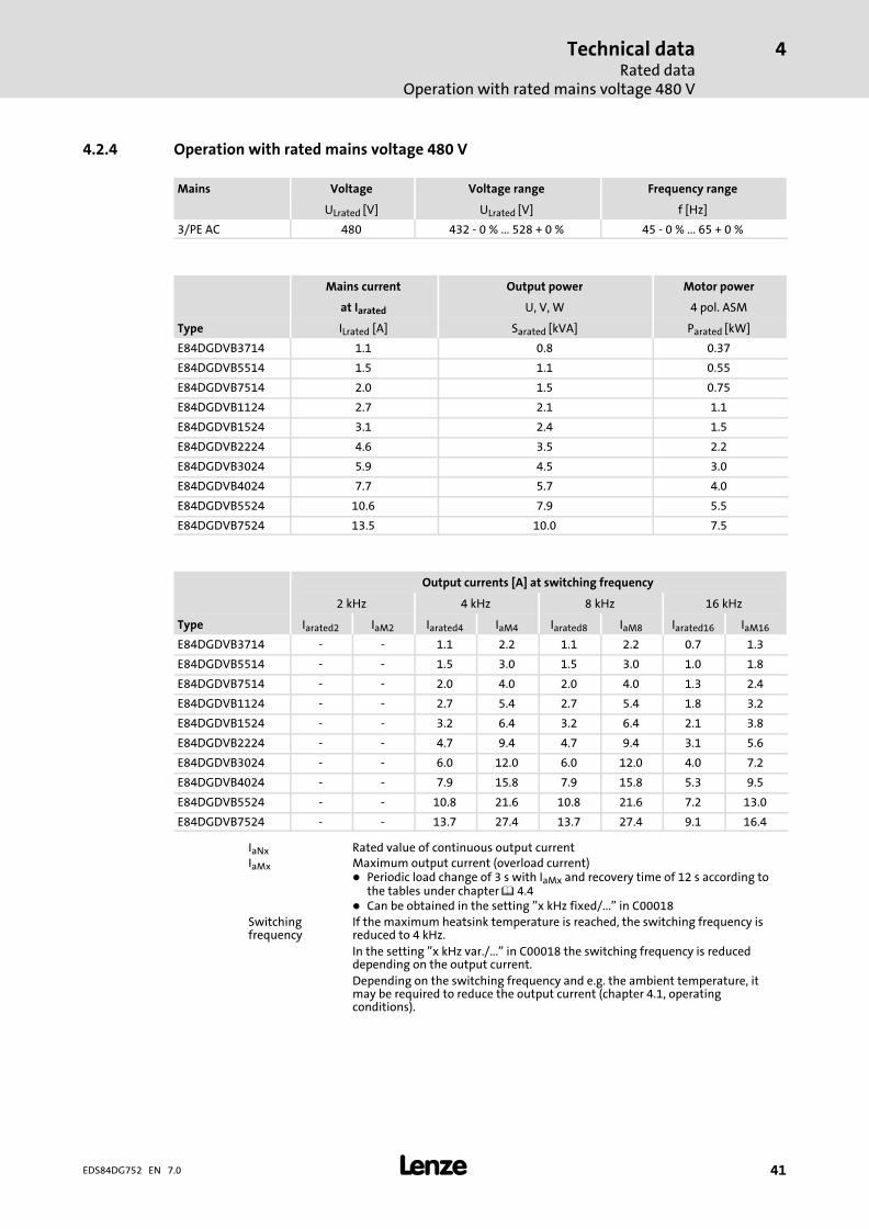
4.2.4 Operation with rated mains voltage 480 V
Mains Voltage Voltage range Frequency range
ULrated [V] ULrated [V] f [Hz]
3/PE AC 480 432 − 0 % ... 528 + 0 % 45 − 0 % ... 65 + 0 %
Mains current Output power Motor power
at Iarated U, V, W 4 pol. ASM
Type ILrated [A] Sarated [kVA] Parated [kW]
E84DGDVB3714 1.1 0.8 0.37
E84DGDVB5514 1.5 1.1 0.55
E84DGDVB7514 2.0 1.5 0.75
E84DGDVB1124 2.7 2.1 1.1
E84DGDVB1524 3.1 2.4 1.5
E84DGDVB2224 4.6 3.5 2.2
E84DGDVB3024 5.9 4.5 3.0
E84DGDVB4024 7.7 5.7 4.0
E84DGDVB5524 10.6 7.9 5.5
E84DGDVB7524 13.5 10.0 7.5
Output currents [A] at switching frequency
2 kHz 4 kHz 8 kHz 16 kHz
Type Iarated2 IaM2 Iarated4 IaM4 Iarated8 IaM8 Iarated16 IaM16
E84DGDVB3714 − − 1.1 2.2 1.1 2.2 0.7 1.3
E84DGDVB5514 − − 1.5 3.0 1.5 3.0 1.0 1.8
E84DGDVB7514 − − 2.0 4.0 2.0 4.0 1.3 2.4
E84DGDVB1124 − − 2.7 5.4 2.7 5.4 1.8 3.2
E84DGDVB1524 − − 3.2 6.4 3.2 6.4 2.1 3.8
E84DGDVB2224 − − 4.7 9.4 4.7 9.4 3.1 5.6
E84DGDVB3024 − − 6.0 12.0 6.0 12.0 4.0 7.2
E84DGDVB4024 − − 7.9 15.8 7.9 15.8 5.3 9.5
E84DGDVB5524 − − 10.8 21.6 10.8 21.6 7.2 13.0
E84DGDVB7524 − − 13.7 27.4 13.7 27.4 9.1 16.4
IaNx Rated value of continuous output currentIaMx Maximum output current (overload current)
� Periodic load change of 3 s with IaMx and recovery time of 12 s according tothe tables under chapter � 4.4
� Can be obtained in the setting "x kHz fixed/..." in C00018Switchingfrequency
If the maximum heatsink temperature is reached, the switching frequency isreduced to 4 kHz.In the setting "x kHz var./..." in C00018 the switching frequency is reduceddepending on the output current.Depending on the switching frequency and e.g. the ambient temperature, itmay be required to reduce the output current (chapter 4.1, operatingconditions).

Technical dataRated dataOperation with rated mains voltage 480 V
4
� 42 EDS84DG752 EN 7.0
Fuses and cable cross−sections
ƒ Point−to−point connection − direct wiring of the mains voltage − typical fusing
Operation
Type Installation according to EN 60204−1 1) Installation accordingto UL 2)
FI 3)
� � L1, L2, L3 − laying system � L1, L2, L3
B2 C F
[A] [A] [mm2] [mm2] [mm2] [A] [AWG] [mA]
E84DGDVB3714 C 16 16 2.5 − − 15 12 � 30
E84DGDVB5514 C 16 16 2.5 − − 15 12 � 30
E84DGDVB7514 C 16 16 2.5 − − 15 12 � 30
E84DGDVB1124 C 16 16 2.5 − − 15 12 � 30
E84DGDVB1524 C 16 16 2.5 − − 15 12 � 30
E84DGDVB2224 C 16 16 2.5 − − 15 12 � 30
E84DGDVB3024 C 16 16 2.5 − − 15 12 � 30
E84DGDVB4024 C20 20 4.0 − − 20 12 � 30
E84DGDVB5524 C20 20 4.0 − − 20 12 � 30
E84DGDVB7524 C 20 20 4.0 − − 20 12 � 30
ƒ Multiple connection − loop−through connection of the mains voltage − maximumfusing
Operation
Type Installation according to EN 60204−1 1) Installation accordingto UL 2)
FI 3)
� � L1, L2, L3 − laying system � L1, L2, L3
B2 C F
[A] [A] [mm2] [mm2] [mm2] [A] [AWG] [mA]
E84DGDVB3714 C 32 32 6.0 − − 15 12 � 30
E84DGDVB5514 C 32 32 6.0 − − 15 12 � 30
E84DGDVB7514 C 32 32 6.0 − − 15 12 � 30
E84DGDVB1124 C 32 32 6.0 − − 15 12 � 30
E84DGDVB1524 C 32 32 6.0 − − 15 12 � 30
E84DGDVB2224 C 32 32 6.0 − − 25 10 � 30
E84DGDVB3024 C 32 32 6.0 − − 25 10 � 30
E84DGDVB4024 C 50 50 16.0 − − 50 6 � 30
E84DGDVB5524 C 50 50 16.0 − − 50 6 � 30
E84DGDVB7524 C 50 50 16.0 − − 50 6 � 30
1) The data are recommendations. Other designs/laying systems can be implemented (e.g. in accordance with VDE0298−4). The cable cross−sections apply under the following conditions: Use of PVC−insulated copper cables,conductor temperature < 70 °C, ambient temperature < 45°C, no bundling of cables or cores, three loaded cores.
2) Only use UL−approved cables, fuses and fuse holders.UL fuse: voltage � 500 V, tripping characteristic for instance "CC". The cable cross−sections apply under the followingconditions: conductor temperature < 75 °C, ambient temperature < 45°C.
3) Universal−current sensitive earth−leakage circuit breaker, short−time delayed� Circuit breaker� Fuse of gG/gL utilisation category or semiconductor fuses of gRL utilisation category� FuseObserve national and regional regulations

Technical dataRated data
Operation with increased power on a 480 V system
4
� 43EDS84DG752 EN 7.0
4.2.5 Operation with increased power on a 480 V system
In continuous operation, the controllers can be actuated with a more powerful motor. Theoverload capacity is limited to 120 %. Typical applications are pumps with a quadratic loadcharacteristic, or fans.
� Note!
Operation with an increased rated power is only permitted ...ƒ with the rated data specified for the controller.
ƒ within the mains voltage range specified.
ƒ with the switching frequency 4 kHz.
ƒ at a max. ambient temperature of 40 °C
ƒ with the fuses and cable cross−sections specified for this operation.ƒ after parameterisation according to the specifications (cf. EDS84DM...
software manual)
Mains Voltage Voltage range Frequency range
ULrated [V] ULrated [V] f [Hz]
3/PE AC 480 432 − 0 % ... 528 + 0 % 45 − 0 % ... 65 + 0 %
Mains current Output power Motor power
at Iarated U, V, W 4 pol. ASM
Type ILrated [A] Sarated [kVA] Parated [kW]
E84DGDVB3714 1.3 1.0 0.55
E84DGDVB5514 1.8 1.3 0.75
E84DGDVB7514 2.4 1.8 1.1
E84DGDVB1124 3.2 2.4 1.5
E84DGDVB1524 1) 3.8 3.0 1.8
E84DGDVB2224 5.6 4.1 2.2
E84DGDVB3024 1) 7.2 5.3 4.0
E84DGDVB4024 9.3 6.8 5.5
E84DGDVB5524 12.8 9.4 7.5
E84DGDVB7524 2) 16.3 11.9 9.2
1) Operation with increased rated power for motor mounting only.2) Motor connection with plug (Q8) not permissible.

Technical dataRated dataOperation with increased power on a 480 V system
4
� 44 EDS84DG752 EN 7.0
Output currents [A] at switching frequency
2 kHz 4 kHz 8 kHz 16 kHz
Type Iarated2 IaM2 Iarated4 IaM4 Iarated8 IaM8 Iarated16 IaM16
E84DGDVB3714 − − 1.3 2.2 − − − −
E84DGDVB5514 − − 1.8 3.0 − − − −
E84DGDVB7514 − − 2.4 4.0 − − − −
E84DGDVB1124 − − 3.2 5.4 − − − −
E84DGDVB1524 1) − − 3.8 6.4 − − − −
E84DGDVB2224 − − 5.6 9.4 − − − −
E84DGDVB3024 1) − − 7.2 12.0 − − − −
E84DGDVB4024 − − 9.5 15.8 − − − −
E84DGDVB5524 − − 13.0 21.6 − − − −
E84DGDVB7524 2) − − 16.4 33.0 − − − −
1) Operation with increased rated power for motor mounting only.2) Motor connection with plug (Q8) not permissible.
IaNx Rated value of continuous output currentIaMx Maximum output current (overload current)
� Periodic load change of 3 s with IaMx and recovery time of 12 s according tothe tables under chapter � 4.4
Fuses and cable cross−sections
The data/recommendations for operation at a rated mains voltage of 480 V can be applied.
(� 38)
Technical dataDevice protection by current derating
Frame Unit / Field Package without switch
4
� 45EDS84DG752 EN 7.0
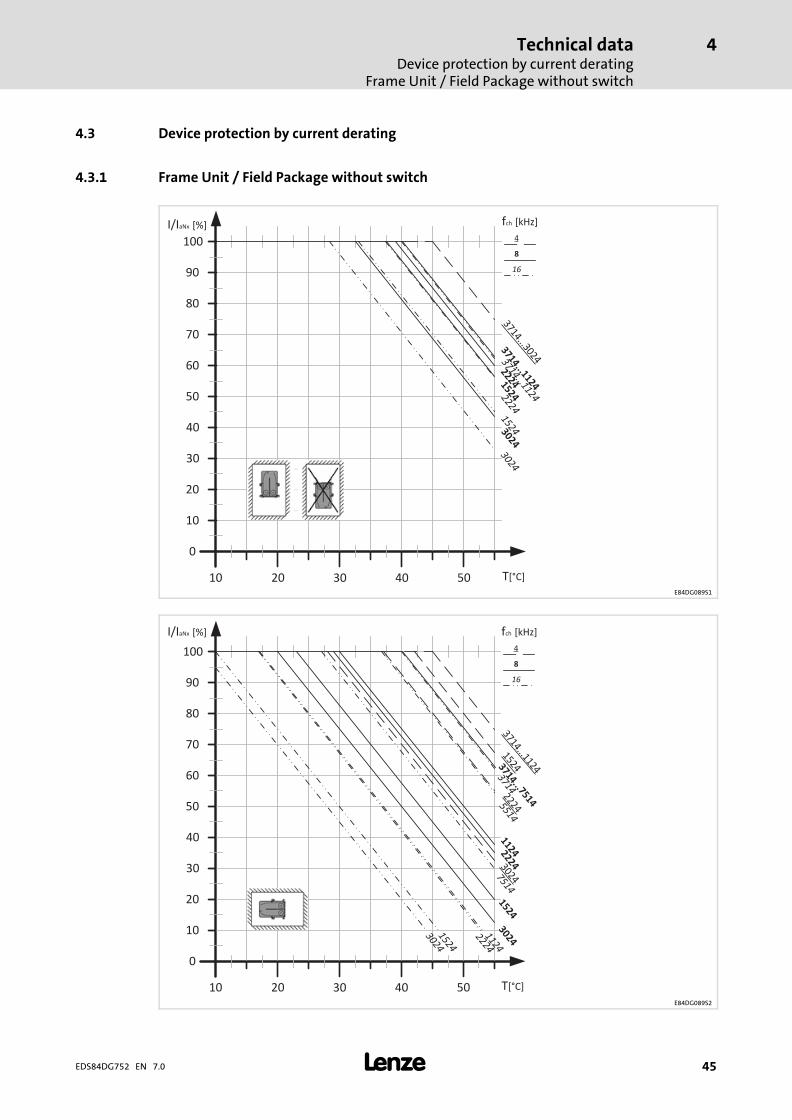
4.3 Device protection by current derating
4.3.1 Frame Unit / Field Package without switch
100
90
80
70
60
50
40
30
20
10
0
10 20 30 40 50
I/IaNx [%]
15241524
fch [kHz]
16
8
4
3714...1124
3714...30243714...112422243024
30242224
T[°C]E84DG089S1
100
90
80
70
60
50
40
30
20
10
0
10 20 30 40 50
I/IaNx [%]
1524
1524
fch [kHz]
16
8
4
3714...7514
3714...1124
2224
3024
30242224
15242224
30241124
37145514
7514
1124
T[°C]E84DG089S2

Technical dataDevice protection by current deratingFrame Unit / Field Package without switch
4
� 46 EDS84DG752 EN 7.0
100
90
80
70
60
50
40
30
20
10
0
10 20 30 40 50
I/IaNx [%]
1524
1524
fch [kHz]
16
8
4
3714...1124
3714...1524
3714...5514
2224
30243024
22242224
30247514
1124
T[°C]E84DG089S3

Technical dataDevice protection by current derating
Frame Unit / Field Package with switch
4
� 47EDS84DG752 EN 7.0
4.3.2 Frame Unit / Field Package with switch
100
90
80
70
60
50
40
30
20
10
0
10 20 30 40 50
I/IaNx [%]
15241524
fch [kHz]
16
8
4
112411243714...7514
75143714...2224
3714...5514
30242224
30242224
3024
T[°C]E84DG090 S1
100
90
80
70
60
50
40
30
20
10
0
10 20 30 40 50
I/IaNx [%]
1524
1524
fch [kHz]
16
8
4
11245514
3714...5514
75143714...1124
37142224
3024
2224
3024
15242224
30247514
1124
T[°C]E84DG090 S2
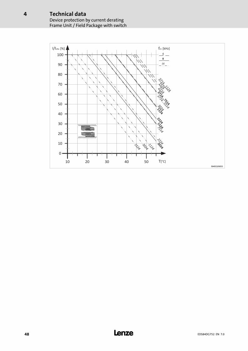
Technical dataDevice protection by current deratingFrame Unit / Field Package with switch
4
� 48 EDS84DG752 EN 7.0
T[°C]
100
90
80
70
60
50
40
30
20
10
0
10 20 30 40 50
1524
1524
fch [kHz]
16
8
4
1124
1124
3714...7514
75143714...1124
3714...5514
15242224
302422243024
22243024
I/IaNx [%]
E84DG090S5
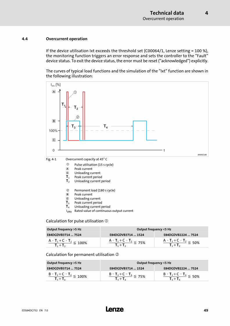
Technical dataOvercurrent operation
4
� 49EDS84DG752 EN 7.0
4.4 Overcurrent operation
If the device utilisation Ixt exceeds the threshold set (C00064/1, Lenze setting = 100 %),the monitoring function triggers an error response and sets the controller to the "Fault"device status. To exit the device status, the error must be reset ("acknowledged") explicitly.
The curves of typical load functions and the simulation of the "Ixt" function are shown inthe following illustration:
t0
100%
�
�
�
I [%]aNx
T2
T3
T4
T1
�
�
8400IZ180
Fig. 4−1 Overcurrent capacity at 45° C
� Pulse utilisation (15 s cycle)� Peak current� Unloading currentT1 Peak current periodT2 Unloading current period
� Permanent load (180 s cycle)� Peak current� Unloading currentT3 Peak current periodT4 Unloading current periodIaNx Rated value of continuous output current
Calculation for pulse utilisation �
Output frequency >5�Hz Output frequency <5�Hz
E84DGDVB3714�...�7524 E84DGDVB3714�...�1524 E84DGDVB2224�...�7524
A � T1�C � T2
T1�T2� 100%
A � T1�C � T2
T1�T2� 75%
A � T1�C � T2
T1�T2� 50%
Calculation for permanent utilisation �
Output frequency >5�Hz Output frequency <5�Hz
E84DGDVB3714�...�7524 E84DGDVB3714�...�1524 E84DGDVB2224�...�7524
B � T3�C � T4
T3�T4� 100%
B � T3�C � T4
T3�T4� 75%
B � T3�C � T4
T3�T4� 50%

Technical dataOvercurrent operation
4
� 50 EDS84DG752 EN 7.0
Type
Iamax/IaN8 [%] in 15−s cycle �
f = 2 kHz f = 4 kHz f = 8 kHz f = 16 kHz
� � � � � � � �
E84DGDVB3714
− − 200 75 200 75 120 50
E84DGDVB5514
E84DGDVB7514
E84DGDVB1124
E84DGDVB1524
E84DGDVB2224
E84DGDVB3024
E84DGDVB4024
E84DGDVB5524
E84DGDVB7524
Type
Iamax/IaN8 [%] in 180−s cycle �
f = 2 kHz f = 4 kHz f = 8 kHz f = 16 kHz
� � � � � � � �
E84DGDVB3714
− − 150 75 150 75 100 50
E84DGDVB5514
E84DGDVB7514
E84DGDVB1124
E84DGDVB1524
E84DGDVB2224
E84DGDVB3024
E84DGDVB4024
E84DGDVB5524
E84DGDVB7524
� Tip!
For calculations of application−specific cycles please contact your Lenze contactperson.

Technical dataSwitching frequency reduction
4
� 51EDS84DG752 EN 7.0
4.5 Switching frequency reduction
Under certain operating conditions, the maximum output current is limited for all devices:
ƒ When the maximum heatsink temperature is exceeded, the controller switchesfrom 16 kHz to 8 kHz and from 8 kHz to 4 kHz, irrespective of the switchingfrequency mode. This function can be deactivated via C00144.
If the heatsink temperature increases above 105 °C, the controller is inhibited and theerror message "OH1: Heatsink overtemperature" is output.
The error response is also triggered when the switching frequency reduction isdeactivated.

Technical dataPower terminals8400 motec 0.37�...�3�kW
4
� 52 EDS84DG752 EN 7.0
4.6 Power terminals
4.6.1 8400 motec 0.37�...�3�kW
X1 − Wiring Unit
E84DG123
Mains
Terminal data
Name Power Conductor cross−section[mm2][AWG]
Tightening torque[Nm][lb−in]
�
X1
L1, L2, L3 0.37�...�1.5�kW 1 ... 418 ... 10 0.5
4.43.5 x 0.6
2 x 0.5 ... 2 x 2.5 1)
18 ... 10
2.2�...�3.0�kW 1 ... 618 ... 8 0.8
7.03.5 x 0.6
2 x 0.5 ... 2 x 2.5 1)
18 ... 8
�
PE 0.37�...�1.5�kW 1 ... 418 ... 10
1.716
8 x 1.2
2.2�...�3.0�kW 1 ... 618 ... 8
1.716
8 x 1.2
1) For looping−through connections (daisy chain) => two conductors with TWIN wire end ferrule
Features
Name Description Rated value
X1
L1, L2, L3 Mains phases See rated data

Technical dataPower terminals
8400 motec 0.37�...�3�kW
4
� 53EDS84DG752 EN 7.0
Motor
Terminal data
Name Power Conductor cross−section[mm2][AWG]
Tightening torque[Nm][lb−in]
�
X1
U, V, W 0.37�...�1.5�kW 1 ... 418 ... 10
0.54.4
3.5 x 0.6
2.2�...�3.0�kW 1 ... 618 ... 8
0.87.0
3.5 x 0.6
�
PE 0.37�...�1.5�kW 1 ... 418 ... 10
1.716
8 x 1.2
2.2�...�3.0�kW 1 ... 618 ... 8
1.716
8 x 1.2
Features
Name Description Rated value
X1
U, V, W Motor phases See rated data
Motor temperature monitoring
Danger!
Hazardous electrical voltage
Terminals T1, T2 are on DC−bus voltage potential.
Possible consequences:
ƒ Death or severe injuries when touching the power terminals.
Protective measures:
ƒ Before working on the terminals, disconnect mains and wait for at least3 minutes.
ƒ Check whether the terminals are deenergised.
Terminal data
Name Power Conductor cross−section[mm2][AWG]
Tightening torque[Nm][lb−in]
�
X1
T1, T2 0.37�...�1.5�kW 1.516
0.54.4
3.5 x 0.6
2.2�...�3.0�kW 1 ... 618 ... 8
0.87.0
3.5 x 0.6
Features
Name Description Rated value
X1
T1, T2 Motor temperature monitoring See rated dataDanger! Hazardous electrical voltage.� T1 and T2 have DC−bus voltage potential .

Technical dataPower terminals8400 motec 0.37�...�3�kW
4
� 54 EDS84DG752 EN 7.0
Motor holding brake
Terminal data
Name Power Conductor cross−section[mm2][AWG]
Tightening torque[Nm][lb−in]
�
X1
BD1 (+)BD2 (−)
˘ 1.516
0.54.4
3.5 x 0.6
Features
Name Description Rated value
X1
BD1 (+)BD2 (−)
Connection of a motor holding brake
Output voltage(depending on the mains voltage)
DC 180 V
DC 215 V
Max. output current 0.3 A
Max. output power 55 VA
Time−dependent behaviour See software manual, chapter "Holding brakecontrol/parameter setting"
Short−circuit−proof No
Reset and switch−on behaviour Outputs are switched off
Operating frequency Max. 30/min
Brake resistor
Terminal data
Name Power Conductor cross−section[mm2][AWG]
Tightening torque[Nm][lb−in]
�
X1
Rb1, Rb2 ˘ 1.516
0.54.4
3.5 x 0.6
Features
Name Description Rated value
X1
Rb1, Rb2 Brake resistor See rated data

Technical dataPower terminals
8400 motec 4�...�7.5�kW
4
� 55EDS84DG752 EN 7.0
4.6.2 8400 motec 4�...�7.5�kW
X1/X2
E84DG124
Mains
Terminal data
Name Power Conductor cross−section[mm2][AWG]
Tightening torque[Nm][lb−in]
�
X1
L1, L2, L3 4.0�...�7.5�kW 1 ... 1618 ... 6 1.4
12PZ 2
5.5 x 102 x 1 ... 2 x 6 1)
18 ... 6
�
PE 4.0�...�7.5�kW 1 ... 1618 ... 6
1.715
8 x 1.2
1) For looping−through connections (daisy chain) => two conductors with TWIN wire end ferrule
� Note!
Terminal X1 is not pluggable.
Features
Name Description Rated value
X1
L1, L2, L3 Mains phases See rated data

Technical dataPower terminals8400 motec 4�...�7.5�kW
4
� 56 EDS84DG752 EN 7.0
Motor
Terminal data
Name Power Conductor cross−section[mm2][AWG]
Tightening torque[Nm][lb−in]
�
X2
U, V, W 4.0�...�7.5�kW 1 ... 618 ... 8
0.87
PH 13.5 x 0.6
�
PE 4.0�...�7.5�kW 1 ... 1618 ... 6
1.715
8 x 1.2
Features
Name Description Rated value
X2
U, V, W Motor phases See rated data
Motor temperature monitoring
Danger!
Hazardous electrical voltage
Terminals T1, T2 are on DC−bus voltage potential.
Possible consequences:
ƒ Death or severe injuries when touching the power terminals.
Protective measures:
ƒ Before working on the terminals, disconnect mains and wait for at least3 minutes.
ƒ Check whether the terminals are deenergised.
Terminal data
Name Power Conductor cross−section[mm2][AWG]
Tightening torque[Nm][lb−in]
�
X2
T1, T2 0.37�...�1.5�kW 1.516
0.54.4
3.5 x 0.6
2.2�...�3.0�kW 1 ... 618 ... 8
0.87.0
3.5 x 0.6
Features
Name Description Rated value
X2
T1, T2 Motor temperature monitoring See rated dataDanger! Hazardous electrical voltage.� T1 and T2 have DC−bus voltage potential .

Technical dataPower terminals
8400 motec 4�...�7.5�kW
4
� 57EDS84DG752 EN 7.0
Motor holding brake
Terminal data
Name Power Conductor cross−section[mm2][AWG]
Tightening torque[Nm][lb−in]
�
X2
BD1 (+)BD2 (−)
˘ 1.516
0.54.4
3.5 x 0.6
Features
Name Description Rated value
X2
BD1 (+)BD2 (−)
Connection of a motor holding brake
Output voltage(depending on the mains voltage)
DC 180 V
DC 215 V
Max. output current 0.3 A
Max. output power 55 VA
Time−dependent behaviour See software manual, chapter "Holding brakecontrol/parameter setting"
Short−circuit−proof No
Reset and switch−on behaviour Outputs are switched off
Operating frequency Max. 30/min
Brake resistor
Terminal data
Name Power Conductor cross−section[mm2][AWG]
Tightening torque[Nm][lb−in]
�
X2
Rb1, Rb2 ˘ 1.516
0.54.4
3.5 x 0.6
Features
Name Description Rated value
X2
Rb1, Rb2 Brake resistor See rated data

Technical data8400 motec Field Package8400 motec 4�...�7.5�kW
4
� 58 EDS84DG752 EN 7.0
4.6.3 8400 motec Field Package
X1/X100 − Frame Unit
E84DG125
Mains
Terminal data
Name Power Conductor cross−section[mm2][AWG]
Tightening torque[Nm][lb−in]
�
X100
L1, L2, L3 0.37�...�1.5�kW 1 ... 418 ... 10 0.5
4.43.5 x 0.6
2 x 0.5 ... 2 x 2.5 1)
18 ... 10
2.2�...�3.0�kW 1 ... 618 ... 8 0.8
7.03.5 x 0.6
2 x 0.5 ... 2 x 2.5 1)
18 ... 8
�
PE 0.37�...�1.5�kW 1 ... 418 ... 10
1.716
8 x 1.2
2.2�...�3.0�kW 1 ... 618 ... 8
1.716
8 x 1.2
1) For looping−through connections (daisy chain) => two conductors with TWIN wire end ferrule
Features
Name Description Rated value
X1
L1, L2, L3 Mains phases See rated data
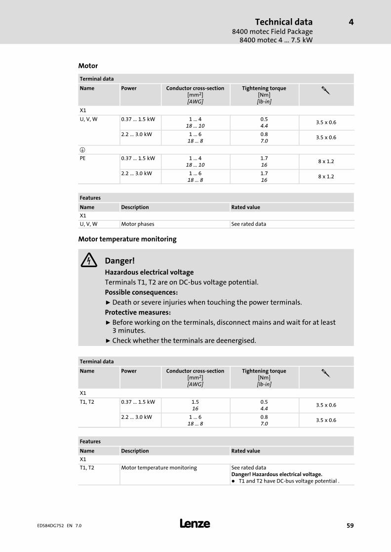
Technical data8400 motec Field Package
8400 motec 4�...�7.5�kW
4
� 59EDS84DG752 EN 7.0
Motor
Terminal data
Name Power Conductor cross−section[mm2][AWG]
Tightening torque[Nm][lb−in]
�
X1
U, V, W 0.37�...�1.5�kW 1 ... 418 ... 10
0.54.4
3.5 x 0.6
2.2�...�3.0�kW 1 ... 618 ... 8
0.87.0
3.5 x 0.6
�
PE 0.37�...�1.5�kW 1 ... 418 ... 10
1.716
8 x 1.2
2.2�...�3.0�kW 1 ... 618 ... 8
1.716
8 x 1.2
Features
Name Description Rated value
X1
U, V, W Motor phases See rated data
Motor temperature monitoring
Danger!
Hazardous electrical voltage
Terminals T1, T2 are on DC−bus voltage potential.
Possible consequences:
ƒ Death or severe injuries when touching the power terminals.
Protective measures:
ƒ Before working on the terminals, disconnect mains and wait for at least3 minutes.
ƒ Check whether the terminals are deenergised.
Terminal data
Name Power Conductor cross−section[mm2][AWG]
Tightening torque[Nm][lb−in]
�
X1
T1, T2 0.37�...�1.5�kW 1.516
0.54.4
3.5 x 0.6
2.2�...�3.0�kW 1 ... 618 ... 8
0.87.0
3.5 x 0.6
Features
Name Description Rated value
X1
T1, T2 Motor temperature monitoring See rated dataDanger! Hazardous electrical voltage.� T1 and T2 have DC−bus voltage potential .

Technical data8400 motec Field Package8400 motec 4�...�7.5�kW
4
� 60 EDS84DG752 EN 7.0
Motor holding brake
Terminal data
Name Power Conductor cross−section[mm2][AWG]
Tightening torque[Nm][lb−in]
�
X1
BD1 (+)BD2 (−)
˘ 1.516
0.54.4
3.5 x 0.6
Features
Name Description Rated value
X1
BD1 (+)BD2 (−)
Connection of a motor holding brake
Output voltage(depending on the mains voltage)
DC 180 V
DC 215 V
Max. output current 0.3 A
Max. output power 55 VA
Time−dependent behaviour See software manual, chapter "Holding brakecontrol/parameter setting"
Short−circuit−proof No
Reset and switch−on behaviour Outputs are switched off
Operating frequency Max. 30/min
Brake resistor
Terminal data
Name Power Conductor cross−section[mm2][AWG]
Tightening torque[Nm][lb−in]
�
X1
Rb1, Rb2 ˘ 1.516
0.54.4
3.5 x 0.6
Features
Name Description Rated value
X1
Rb1, Rb2 Brake resistor See rated data
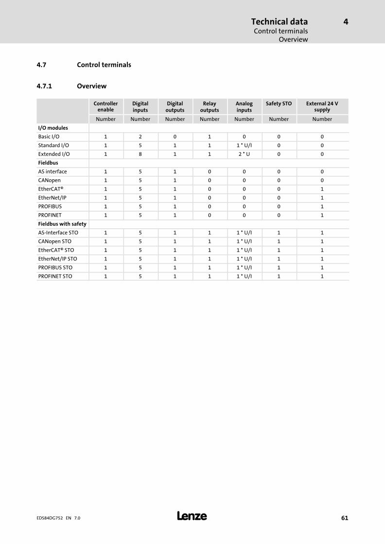
Technical dataControl terminals
Overview
4
� 61EDS84DG752 EN 7.0
4.7 Control terminals
4.7.1 Overview
Controllerenable
Digitalinputs
Digitaloutputs
Relayoutputs
Analoginputs
Safety STO External 24 Vsupply
Number Number Number Number Number Number Number
I/O modules
Basic I/O 1 2 0 1 0 0 0
Standard I/O 1 5 1 1 1 * U/I 0 0
Extended I/O 1 8 1 1 2 * U 0 0
Fieldbus
AS interface 1 5 1 0 0 0 0
CANopen 1 5 1 0 0 0 0
EtherCAT® 1 5 1 0 0 0 1
EtherNet/IP 1 5 1 0 0 0 1
PROFIBUS 1 5 1 0 0 0 1
PROFINET 1 5 1 0 0 0 1
Fieldbus with safety
AS−Interface STO 1 5 1 1 1 * U/I 1 1
CANopen STO 1 5 1 1 1 * U/I 1 1
EtherCAT® STO 1 5 1 1 1 * U/I 1 1
EtherNet/IP STO 1 5 1 1 1 * U/I 1 1
PROFIBUS STO 1 5 1 1 1 * U/I 1 1
PROFINET STO 1 5 1 1 1 * U/I 1 1

Technical dataControl terminalsGeneral data
4
� 62 EDS84DG752 EN 7.0
4.7.2 General data
General data
Feature Value/designation
Analog input, voltage
Value range 0�...�10�V
Value range − Extended I/O only −10�...�+10�V
Resolution 10�bits
Input resistance �80�k�
Sampling frequency 80�Hz (12�ms)
Accuracy ±0.1�V
Electric strength of external voltage −7�...�+30�V
Analog input, current
Value range, parameterisable 0.6�...�+20�mA (0.6�mA corresponds to 0)
4�...�+20�mA, fail−safe
Resolution 10�bits
Input resistance 250��
Input current in the case of an open circuit Display "0" (I�0.6�mA)
Sampling frequency 80�Hz (12�ms)
Typical accuracy ±0.2�mA
Electric strength of external voltage −7�...�+7�V
Digital inputs
Switching level PLC (IEC�61131−2)
Max. input current 11�mA
Digital outputs
Switching level PLC (IEC�61131−2)
Max. output current 50�mA
Relay
Contact NO contact
Connection AC�250�V, 3�A
DC�24�V, 2�A�...�240�V, 0.16�A
24 V supply
External (24E) DC input voltage: +19.2�...�+28.8�VFor supporting communication when the mainsvoltage is disconnected
Internal (24O) DC output voltage, max. 100�mA for inputs/outputsand sensor supply
Interfaces
Extensions Fieldbus via Communication Unit
Safety system 1 safe input for passive/active actuators
Drive interface
Encoder input– Basic I/O– Standard I/O– Extended I/O– CANopen– PROFIBUS– AS−i
Via 2 digital inputs, HTL, 2−track, 7.5�kHz
Encoder input– PROFINET– EtherNet/IP– EtherCAT
Via 2 digital inputs, HTL, 2−track, 10�kHz

Technical dataControl terminals
AS−Interface
4
� 63EDS84DG752 EN 7.0
Standards and application conditions
Feature Value/designation
Type of protection
EN�60529 IP65
Climatic conditions
Storage (EN�60721−3−1) 1K3 (temperature: −30�°C�...�+60�°C)
Operation (EN�60721−3−3) 3K3 (temperature: −30�°C�...�+55�°C)
Transport (EN�60721−3−2) 2K3 (temperature: −30�°C�...�+75�°C)
Insulation voltage to PE reference earth
EN�61800−5−1 UAC 50.0�V
Safety system
Feature Value/designation
Communication module AS−Interface STO, CANopen STO, EtherCAT® STO, EtherNet/IP STO,PROFIBUS STO, PROFINET STO
Certification
EN�ISO�13849−1 PLe, category 4
EN�61800−5−2 SIL�3
EN�62061 SIL�3
IEC�61508 SIL�3
Fail−safe state Safe torque off
4.7.3 AS−Interface
Feature Value/designation
Standard EN�50295 / IEC�62026−2
Communication
Communication profile AS−Interface V3.0
Medium Two−core cable for data and auxiliary power
Network topology Free topology (line, ring, tree, star)
Nodes Slave (single, dual)
Max. 31 standard slaves or safe slaves
Max. 62 A/B slaves
Number of nodes 1�... 31
Max. cable length
Per bus segment lmax 100�m without repeater/extender
300�m with 2 repeaters/extenders
500�m only in star topologies with 2 repeaters/extenders
Baud rate 167�kbps (gross)
53�kbps (net with data transmission efficiency = 32�%)
Rated voltage Urated
, DC
24.0�V

Technical dataControl terminalsCANopen®
4
� 64 EDS84DG752 EN 7.0
4.7.4 CANopen®
Feature Value/designation
Communication
Communication profile CANopen, DS301 V4.02Lenze system bus
Medium DIN�ISO�11898
Baud rate b 20�kbps50�kbps125�kbps250�kbps500�kbps800�kbps1000�kbps
Network topology Line with 120�Ohm terminating resistor on both sides
Nodes SlaveMini master
Number of nodes 63
Number of logic process data channels 2 transmit PDOs and 2 receive PDOs (with 1�...�8�bytes each)
Number of logic parameter datachannels
Max. 2 server SDO channels (with 1�...�8�bytes)
Max. cable length lmax 17�m with 1000�kbps40�m with 800�kbps110�m with 500�kbps290�m with 250�kbps630�m with 125�kbps1500�m with 50�kbps3900�m with 20�kbps8000�m with 10�kbps
Rated voltage Urated
, DC
24.0�V
4.7.5 EtherCAT®
Feature Value/designation
Communication
Communication profile CoE (CANopen over EtherCAT)
Medium CAT5e S7FTP in compliance with ISO/IEC11801 (2002)
Baud rate b 100�kbps
Network topology LineSwitch
Nodes Slave
Number of nodes Max. 65535
Number of logic process data channels 1
Process data words (PCD)
To the master 1�...�10 (max. 20�bytes, 16�bits/word)
From the master 1�...�8 (max. 16�bytes, 16�bits/word)
Parameter data
Max. mailbox size for CoE transfer 128�bytes
Max. cable length
Between two nodes lmax 100�m
Rated voltage Urated
, DC
24.0�V
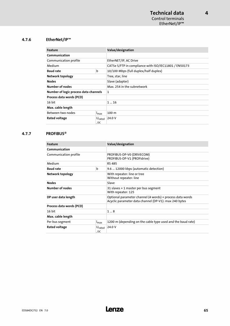
Technical dataControl terminals
EtherNet/IP�
4
� 65EDS84DG752 EN 7.0
4.7.6 EtherNet/IP�
Feature Value/designation
Communication
Communication profile EtherNET/IP, AC Drive
Medium CAT5e S/FTP in compliance with ISO/IEC11801 / EN50173
Baud rate b 10/100�Mbps (full duplex/half duplex)
Network topology Tree, star, line
Nodes Slave (adapter)
Number of nodes Max. 254 in the subnetwork
Number of logic process data channels 1
Process data words (PCD)
16�bit 1�...�16
Max. cable length
Between two nodes lmax 100�m
Rated voltage Urated
, DC
24.0�V
4.7.7 PROFIBUS®
Feature Value/designation
Communication
Communication profile PROFIBUS−DP−V0 (DRIVECOM)PROFIBUS−DP−V1 (PROFIdrive)
Medium RS�485
Baud rate b 9.6�...�12000�kbps (automatic detection)
Network topology With repeater: line or treeWithout repeater: line
Nodes Slave
Number of nodes 31 slaves + 1 master per bus segmentWith repeater: 125
DP user data length Optional parameter channel (4 words) + process data wordsAcyclic parameter data channel (DP−V1): max 240�bytes
Process data words (PCD)
16�bit 1�...�8
Max. cable length
Per bus segment lmax 1200�m (depending on the cable type used and the baud rate)
Rated voltage Urated
, DC
24.0�V

Technical dataControl terminalsPROFINET®
4
� 66 EDS84DG752 EN 7.0
4.7.8 PROFINET®
Feature Value/designation
Communication
Communication profile PROFINET RT conf. class B
Medium CAT5e S/FTP in compliance with ISO/ICE11801 (2002)
Baud rate b 100�MBit/s
Network topology Tree, star, line
Nodes Slave (device)
Number of nodes 31 slaves + 1 master per bus segmentWith repeater: 125
DP user data length to control: 1 ... 10 data words (16 bits/word, max. 20 bytes)from control: 1 ... 8 data words (16 bits/words, max. 16 bytes)
Process data words (PCD)
16�bit 1�...�8
Max. cable length
Per bus segment lmax 100�m
Rated voltage Urated
, DC
24.0�V
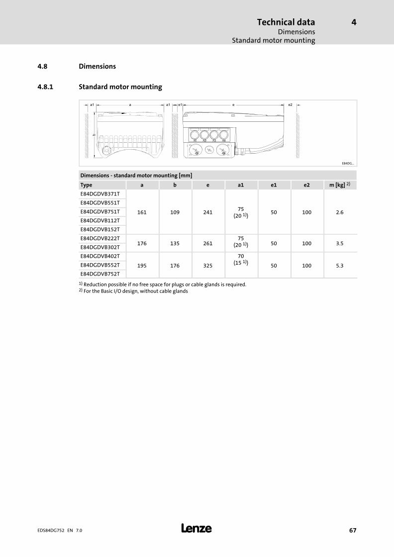
Technical dataDimensions
Standard motor mounting
4
� 67EDS84DG752 EN 7.0
4.8 Dimensions
4.8.1 Standard motor mounting
E84DG...
Dimensions − standard motor mounting [mm]
Type a b e a1 e1 e2 m [kg] 2)
E84DGDVB371T
161 109 24175
(20 1))50 100 2.6
E84DGDVB551T
E84DGDVB751T
E84DGDVB112T
E84DGDVB152T
E84DGDVB222T176 135 261
75(20 1)) 50 100 3.5
E84DGDVB302T
E84DGDVB402T
195 176 325
70(15 1)) 50 100 5.3E84DGDVB552T
E84DGDVB752T
1) Reduction possible if no free space for plugs or cable glands is required.2) For the Basic I/O design, without cable glands
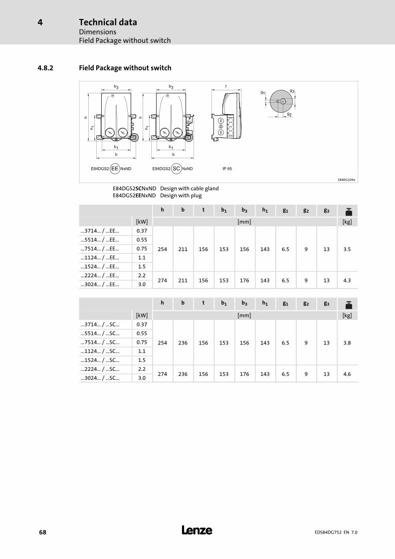
Technical dataDimensionsField Package without switch
4
� 68 EDS84DG752 EN 7.0
4.8.2 Field Package without switch
E84DG109a
E84DGS2SCNxND Design with cable glandE84DGS2EENxND Design with plug
h b t b1 b3 h1 g1 g2 g3
[kW] [mm] [kg]
...3714... / ...EE... 0.37
254 211 156 153 156 143 6.5 9 13 3.5
...5514... / ...EE... 0.55
...7514... / ...EE... 0.75
...1124... / ...EE... 1.1
...1524... / ...EE... 1.5
...2224... / ...EE... 2.2274 211 156 153 176 143 6.5 9 13 4.3
...3024... / ...EE... 3.0
h b t b1 b3 h1 g1 g2 g3
[kW] [mm] [kg]
...3714... / ...SC... 0.37
254 236 156 153 156 143 6.5 9 13 3.8
...5514... / ...SC... 0.55
...7514... / ...SC... 0.75
...1124... / ...SC... 1.1
...1524... / ...SC... 1.5
...2224... / ...SC... 2.2274 236 156 153 176 143 6.5 9 13 4.6
...3024... / ...SC... 3.0

Technical dataDimensions
Field Package with switch
4
� 69EDS84DG752 EN 7.0
4.8.3 Field Package with switch
E84DG094a
E84DGS3LExxND Design with cable glandE84DGS3KCxxND Design with plug
h b t b1 b3 h1 t1 g1 g2 g3 g4
[kW] [mm] [kg]
...3714... / ...LE... 0.37
362 190 134 153 156 245 134 5.5 10 11 8.5 4
...5514... / ...LE... 0.55
...7514... / ...LE... 0.75
...1124... / ...LE... 1.1
...1524... / ...LE... 1.5
...2224... / ...LE... 2.2382 190 134 153 176 245 134 5.5 10 11 8.5 4.8
...3024... / ...LE... 3.0
h b t b1 b3 h1 t1 g1 g2 g3 g4
[kW] [mm] [kg]
...3714... / ...KC... 0.37
362 215 134 153 156 245 134 5.5 10 11 8.5 4.5
...5514... / ...KC... 0.55
...7514... / ...KC... 0.75
...1124... / ...KC... 1.1
...1524... / ...KC... 1.5
...2224... / ...KC... 2.2382 215 134 153 176 245 134 5.5 10 11 8.5 5.3
...3024... / ...KC... 3.0
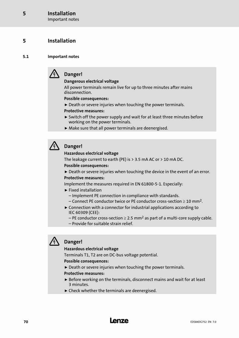
InstallationImportant notes
5
� 70 EDS84DG752 EN 7.0
5 Installation
5.1 Important notes
Danger!
Dangerous electrical voltage
All power terminals remain live for up to three minutes after mainsdisconnection.
Possible consequences:
ƒ Death or severe injuries when touching the power terminals.
Protective measures:
ƒ Switch off the power supply and wait for at least three minutes beforeworking on the power terminals.
ƒ Make sure that all power terminals are deenergised.
Danger!
Hazardous electrical voltage
The leakage current to earth (PE) is > 3.5 mA AC or > 10 mA DC.
Possible consequences:
ƒ Death or severe injuries when touching the device in the event of an error.
Protective measures:
Implement the measures required in EN 61800−5−1. Especially:ƒ Fixed installation
– Implement PE connection in compliance with standards.– Connect PE conductor twice or PE conductor cross−section � 10 mm2.
ƒ Connection with a connector for industrial applications according toIEC 60309 (CEE):– PE conductor cross−section � 2.5 mm2 as part of a multi−core supply cable.– Provide for suitable strain relief.
Danger!
Hazardous electrical voltage
Terminals T1, T2 are on DC−bus voltage potential.
Possible consequences:
ƒ Death or severe injuries when touching the power terminals.
Protective measures:
ƒ Before working on the terminals, disconnect mains and wait for at least3 minutes.
ƒ Check whether the terminals are deenergised.

InstallationImportant notes
5
� 71EDS84DG752 EN 7.0
Stop!
No device protection if the mains voltage is too high
The mains input is not internally fused.
Possible consequences:
ƒ Destruction of the device if the mains voltage is too high.
Protective measures:
ƒ Observe the maximally permissible mains voltage.ƒ Fuse the device correctly on the supply side against mains fluctuations and
voltage peaks.
Stop!
The device contains components that can be destroyed by electrostaticdischarge!
Before working on the device, the personnel must ensure that they are free ofelectrostatic charge by using appropriate measures.
Stop!
Damage of the device
Mounting or dismounting of the controller, especially the Drive Unit candamage or destroy the device.
Possible consequences:
ƒ The drive may respond in an uncontrolled manner and cause furtherdamages.
Protective measures:
ƒ Only mount or dismount the controller in deenergised status.
Stop!
Pluggable terminal strips or plug connections
Plugging or removing the terminal strips or plug connections during operationmay cause high voltages and arcing.
Possible consequences:
ƒ Damage of the devices
Protective measures:
ƒ Switch off device.
ƒ Only plug or remove the terminal strips or plug connections in deenergisedstatus.

InstallationImportant notes
5
� 72 EDS84DG752 EN 7.0
Stop!
Overvoltage at components:
In case of an earth fault in IT systems, intolerable overvoltages may occur inthe plant.
Possible consequences:
Destruction of the device.
Protective measures:
Before using the controller in the IT system, remove the contact screws on thesupply side and the motor side. (� 5.6).
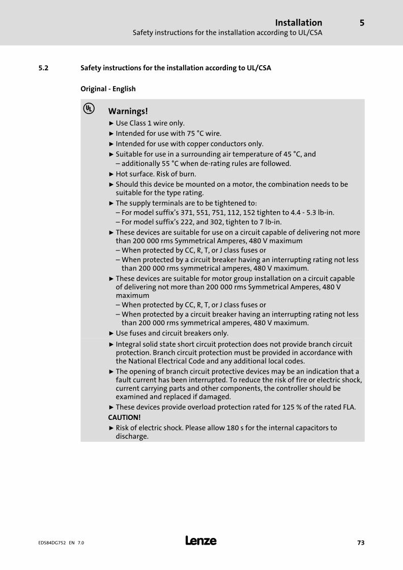
InstallationSafety instructions for the installation according to UL/CSA
5
� 73EDS84DG752 EN 7.0
5.2 Safety instructions for the installation according to UL/CSA
Original − English
� Warnings!
ƒ Use Class 1 wire only.ƒ Intended for use with 75 °C wire.
ƒ Intended for use with copper conductors only.
ƒ Suitable for use in a surrounding air temperature of 45 °C, and– additionally 55 °C when de−rating rules are followed.
ƒ Hot surface. Risk of burn.ƒ Should this device be mounted on a motor, the combination needs to be
suitable for the type rating.
ƒ The supply terminals are to be tightened to:– For model suffix’s 371, 551, 751, 112, 152 tighten to 4.4 − 5.3 lb−in.– For model suffix’s 222, and 302, tighten to 7 lb−in.
ƒ These devices are suitable for use on a circuit capable of delivering not morethan 200�000 rms Symmetrical Amperes, 480 V maximum– When protected by CC, R, T, or J class fuses or– When protected by a circuit breaker having an interrupting rating not less
than 200�000 rms symmetrical amperes, 480 V maximum.ƒ These devices are suitable for motor group installation on a circuit capable
of delivering not more than 200�000 rms Symmetrical Amperes, 480 Vmaximum– When protected by CC, R, T, or J class fuses or– When protected by a circuit breaker having an interrupting rating not less
than 200�000 rms symmetrical amperes, 480 V maximum.
ƒ Use fuses and circuit breakers only.
ƒ Integral solid state short circuit protection does not provide branch circuitprotection. Branch circuit protection must be provided in accordance withthe National Electrical Code and any additional local codes.
ƒ The opening of branch circuit protective devices may be an indication that afault current has been interrupted. To reduce the risk of fire or electric shock,current carrying parts and other components, the controller should beexamined and replaced if damaged.
ƒ These devices provide overload protection rated for 125 % of the rated FLA.
CAUTION!
ƒ Risk of electric shock. Please allow 180 s for the internal capacitors todischarge.

Installation5
� 74 EDS84DG752 EN 7.0
Original − French
� Avertissement !
ƒ Utiliser exclusivement des conducteurs Class 1.ƒ Utiliser des conducteurs 75 °C.
ƒ Utiliser exclusivement des conducteurs en cuivre.
ƒ Convient à une utilisation à une température ambiante maximale de 45 °Cainsi que– 55 °C en cas d’application des règles de réduction de puissance.
ƒ Température élevée en surface. Risque de brûlure.
ƒ En cas de montage de l’équipement sur le moteur, la combinaison doit êtreconforme à la qualification du type.
ƒ Couples de serrage des bornes réseau :– Pour les types contenant le suffixe 371, 551, 751, 112, 152 : 0,5 à 0,6 Nm.– Pour les types contenant le suffixe 222 et 302 : 0,8 Nm.
ƒ Convient aux circuits non susceptibles de délivrer plus de 200�000 ampèressymétriques eff., maximum 480 V– Protection par des fusibles CC de calibre R, T ou J ; ou– Protection par disjoncteur à pouvoir de coupure nominal d’au moins
200�000 ampères symétriques eff., maximum 480 V.
ƒ Convient aux installations de groupe moteur sur des circuits nonsusceptibles de délivrer plus de 200�000 ampères symétriques eff.,maximum 480 V– Protection par des fusibles CC de calibre R, T ou J ; ou– Protection par disjoncteur à pouvoir de coupure nominal d’au moins
200�000 ampères symétriques eff., maximum 480 V.
ƒ Utiliser exclusivement des fusibles et des disjoncteurs.
ƒ La protection statique intégrée n’offre pas la même protection qu’undisjoncteur. Une protection par disjoncteur externe doit être fournie,conformément au National Electrical Code et aux autres dispositionsapplicables au niveau local.
ƒ Le déclenchement des dispositifs de protection du circuit de dérivation peutêtre dû à une coupure qui résulte d’un courant de défaut. Pour limiter lerisque d’incendie ou de choc électrique, examiner les pièces porteuses decourant et les autres éléments du contrôleur ; les remplacer s’ils sontendommagés.
ƒ Ces équipements intègrent une protection contre les surcharges conçuepour se déclencher à 125 % de l’intensité assignée à pleine charge.
ATTENTION !
ƒ Risque de choc électrique. Patientez 180 s pour permettre auxcondensateurs internes de se décharger.

InstallationInstallation according to EMC (installation of a CE−typical drive system)
Shielding
5
� 75EDS84DG752 EN 7.0
5.3 Installation according to EMC (installation of a CE−typical drive system)
Design of the cables
ƒ The cross−section of the PE conductor must be dimensioned according to therelevant national regulations.
ƒ The cables used must comply with the approvals required for the location (e.g. UL).
5.3.1 Shielding
Requirements
ƒ The effectiveness of a shielded cable is reached by:
– Providing a good shield connection through large−surface shield contact.
– Using only braided shields with low shield resistance made of tin−plated ornickel−plated copper braid.
– Using braided shields with an overlap rate > 70 % and an overlap angle of 90 °.
– Keeping unshielded cable ends as short as possible.
Use system cables or shielded cables for these connections:
ƒ Motor
ƒ External brake resistor (� Mounting Instructions of the brake resistor)
ƒ Motor holding brake (shielding is required when being integrated into the motorcable; connection to optional motor brake control)
ƒ Motor temperature monitoring
ƒ Analog signals (inputs and outputs; single−sided shield connection to the controller)
ƒ Fieldbus communication (e.g. CANopen, PROFIBUS, ...)
ƒ Safety system
The following connections need not be shielded:
ƒ Mains
ƒ 24−V supply
ƒ Digital signals (inputs and outputs).
– We recommend to use shielded cables for a cable length from approximately 5 mon or in environments with strong interferences.
Connection system
ƒ Extensively apply shielding directly in the plugs.
ƒ Apply shielding above EMC cable glands.

InstallationInstallation according to EMC (installation of a CE−typical drive system)Motor cable
5
� 76 EDS84DG752 EN 7.0
5.3.2 Motor cable
ƒ Only use shielded motor cables with braids made of tinned or nickel−plated copper.Shields made of steel braids are not suitable.
– The overlap rate of the braid must be at least 70 % with an overlap angle of 90 °.
ƒ The cables used must correspond to the requirements at the location (e.g.EN 60204−1).
ƒ Use Lenze system cables.
ƒ Extensively apply the shielding in the plug and attach it in a way which ensureselectrical conductivity.
ƒ The motor cable is optimally installed if
– it is separated from mains cables and control cables,
– it only crosses mains cables and control cables at right angles,
– it is not interrupted.
ƒ If the motor cable must be opened all the same (e.g. due to chokes, contactors, orterminals):
– The unshielded cable ends may not be longer than 100 mm (depending on thecable cross−section).
– Install chokes, contactors, terminals etc. spatially separated from othercomponents (with a min. distance of 100 mm).
– Install the shield of the motor cable directly before and behind the point ofseparation to the mounting plate with a large surface.
ƒ Connect the shield with a large surface to PE in the terminal box of the motor at themotor housing.
– Metal EMC cable glands at the motor terminal box ensure a large surfaceconnection of the shield with the motor housing.
Wiring on the motor side
Stop!
The motor cable is highly susceptible to interference. Therefore you willachieve an optimum wiring on the motor side if you
ƒ exclusively use shielded and low−capacitance motor cables.
ƒ do not integrate any further cable into the motor cable (e.g. for blowersetc.).
ƒ shield the supply cable for temperature monitoring of the motor (PTC orthermostat) and install it separately from the motor cable.
Special conditions allow you to integrate the supply cable for temperature monitoring ofthe motor into the motor cable: (� 76)

InstallationInstallation according to EMC (installation of a CE−typical drive system)
Control cables
5
� 77EDS84DG752 EN 7.0
� Danger!
Uncontrolled motor movements can occur
If the motor cable is damaged, a short circuit between the brake control cablesand the motor cables can cause motor movements with low torque.
Possible consequences:
ƒ Personnel in the vicinity of the motor can be injured.
Protective measures:
ƒ Install motor cable in a protected way (e.g. in a cable duct).
5.3.3 Control cables
ƒ Control cables must be shielded to minimise interference injections.
ƒ Connect the shield correctly:
– Connect the shield of digital input and output cables at both ends.
– Connect the shield of analog input and output cables at one end (at the drivecontroller).
ƒ To achieve an optimum shielding effect (in case of very long cables, with highinterference) one shield end of analog input and output cables can be connected toPE potential via a capacitor (e.g. 10 nF/250 V) (see sketch).
9300vec043
Fig. 5−1 Shielding of long, analog control cables
5.3.4 Detecting and eliminating EMC interferences
Fault Cause Remedy
Interferences of analogsetpoints of your own orother devices andmeasuring systems
Unshielded motor cable Use shielded motor cable
Shield contact is not extensive enough Carry out optimal shielding as specified
Shield of the motor cable is interruptedby terminal strips, switched, etc.
� Separate components from othercomponent part with a minimumdistance of 100 mm
� Use motor choke/motor filter
Install additional unshielded cablesinside the motor cable (e.g. for motortemperature monitoring)
Install and shield additional cablesseparately
Too long and unshielded cable ends ofthe motor cable
Shorten unshielded cable ends tomaximally 40 mm

InstallationInstallation of 8400 motec pre−assembled on the motorInstallation instructions
5
� 78 EDS84DG752 EN 7.0
5.4 Installation of 8400 motec pre−assembled on the motor
The worksteps to be done during the installation of pre−assembled 8400 motec controllersdepend on the selected connection type of the Wiring Unit:
ƒ Plugs
ƒ Cable gland (M25)
5.4.1 Installation instructions
ƒ If the cooling air is polluted (fluff, (conductive) dust, soot, aggressive gases), takeadequate countermeasures, as e.g.:
– Regular cleaning of the cooling ribs at the controller
– Separate air guide
ƒ Possible mounting position:
– Observe information on mounting conditions in the chapter "Technical data".
ƒ Maintain the specified free spaces above and below the controller to otherinstallations!
ƒ Ensure untroubled cooling and exhaust air flow.
– Arrangement of several devices only to the sides
5.4.2 Plug at the Wiring Unit
The motor has already been wired with the Wiring Unit by the manufacturer. Make surethat the plug assignment of the mains cable complies with the plug at the Wiring Unit. Youmust plug on and lock the mains cable with the suitable plug.
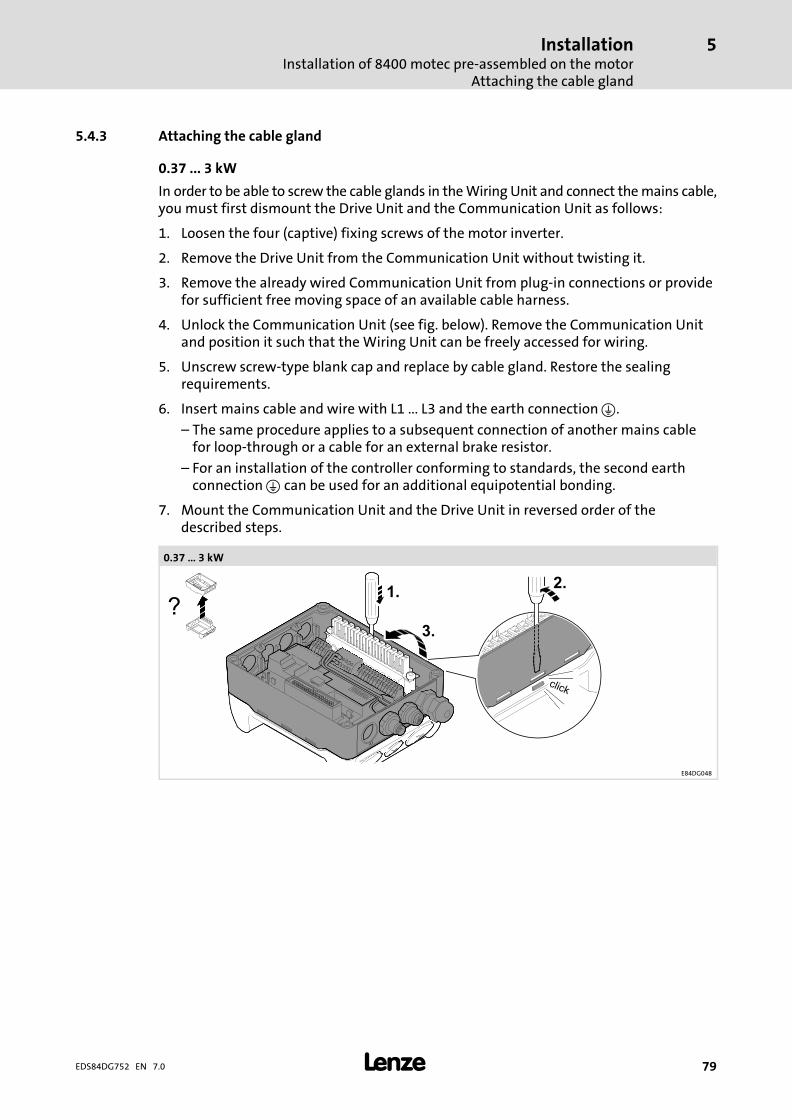
InstallationInstallation of 8400 motec pre−assembled on the motor
Attaching the cable gland
5
� 79EDS84DG752 EN 7.0
5.4.3 Attaching the cable gland
0.37 ... 3 kW
In order to be able to screw the cable glands in the Wiring Unit and connect the mains cable,you must first dismount the Drive Unit and the Communication Unit as follows:
1. Loosen the four (captive) fixing screws of the motor inverter.
2. Remove the Drive Unit from the Communication Unit without twisting it.
3. Remove the already wired Communication Unit from plug−in connections or providefor sufficient free moving space of an available cable harness.
4. Unlock the Communication Unit (see fig. below). Remove the Communication Unitand position it such that the Wiring Unit can be freely accessed for wiring.
5. Unscrew screw−type blank cap and replace by cable gland. Restore the sealingrequirements.
6. Insert mains cable and wire with L1 ... L3 and the earth connection �.
– The same procedure applies to a subsequent connection of another mains cablefor loop−through or a cable for an external brake resistor.
– For an installation of the controller conforming to standards, the second earthconnection � can be used for an additional equipotential bonding.
7. Mount the Communication Unit and the Drive Unit in reversed order of thedescribed steps.
0.37 � 3 kW
E84DG048

InstallationInstallation of 8400 motec pre−assembled on the motorAttaching the cable gland
5
� 80 EDS84DG752 EN 7.0
4 ... 7.5 kW
In order to be able to screw the cable glands into the Drive Unit and connect the mainscable, you must first dismount the Communication Unit as follows:
1. Remove the already wired Communication Unit from plug−in connections or providefor sufficient free moving space of an available cable harness.
2. Loosen the four (captive) screws of the cover of the Communication Unit completelyand remove the cover.
3. Pull the hinged socket connector carefully from the counter plug and turn it into anupright position. Remove the Communication Unit abziehen and position it in such away that the Drive Unit is sufficiently freely accessible for wiring.
4. Unscrew screw−type blank cap and replace by cable gland. Restore the sealingrequirements.
5. Insert mains cable and wire with L1 ... L3 and the earth connection �.
– The same procedure applies to a subsequent connection of another mains cablefor loop−through or a cable for an external brake resistor.
6. Re−assemble the frequency inverter in reversed order of the described steps.

InstallationRetrofitting the 8400 motec controller
Installation instructions
5
� 81EDS84DG752 EN 7.0
5.5 Retrofitting the 8400 motec controller
8400 motec motor inverters for retrofitting existing drives and motors are supplied as setso that they can be mounted directly without previous dismounting. A set consists ofcomponents which are packaged and marked separately:
ƒ Wiring Unit, marked with � − WU
ƒ Communication Unit, marked with � − CU
ƒ Drive Unit, marked with � − DU
ƒ Accessories (optional), marked with � − opt x
Before working on an existing drive, make sure that the system is isolated from supply andprotected against restart.
5.5.1 Installation instructions
ƒ If the cooling air is polluted (fluff, (conductive) dust, soot, aggressive gases), takeadequate countermeasures, as e.g.:
– Regular cleaning of the cooling ribs at the controller
– Separate air guide
ƒ Possible mounting position:
– Observe information on mounting conditions in the chapter "Technical data".
ƒ Maintain the specified free spaces above and below the controller to otherinstallations!
ƒ Ensure untroubled cooling and exhaust air flow.
– Arrangement of several devices only to the sides
For mounting, use the screws of the motor terminal box. The installation material mustensure a durable mechanical connection.
If screws must be replaced, we recommend the following, depending on the motor framesize:
ƒ M4/M5/M6 cheese head screw, hexagon socket, according to DIN 912/ISO 4762
ƒ M4/M5/M6 cheese head screw, torx, according to ISO 14579
5.5.2 Preparing a motor for the 8400 motec installation
In order to install the 8400 motec, you must first remove the terminal box housing. In caseof a standard motor, proceed as follows:
1. After loosening the screws, remove the terminal box cover.
2. Loosening the screws of the terminal box housing. Keep the screws for laterfastening of the WU.
3. Remove the terminal box housing and make sure that the seal for the terminal boxflange is kept for further use with the WU.
4. Usually, no measures have to be taken at the motor terminal block to mount theWU.
InstallationRetrofitting the 8400 motec controllerMounting the Wiring Unit
5
� 82 EDS84DG752 EN 7.0
5.5.3 Mounting the Wiring Unit
0.37 ... 3 kW
Before being mounted, the WU can be extended with accessories. If there is sufficientspace, accessories can also be mounted subsequently if required. The plug connector in theWU should be removed for easier handling and later wiring.
Proceed as follows:
1. Remove the plug connector.
2. Remove the blanking plugs from the WU that are to be replaced by cable glands oraccessories for plug connection.
3. Mount the cable glands or the accessories for plug connection considering thesealing requirements.
4. Mount the WU onto the terminal box flange with the existing seal and screws.Earthing is achieved by forced contacting.
5. Install the mains connection cable and, if required, additional cables for the externalbrake resistor and/or motor holding brake.
6. Wire the mains connection, the brake resistor and/or motor holding brake (ifrequired) to the plug connector. The PE conductor of the mains cable must beconnected to one of the earthing connectors �in the WU.
– In order to ensure compliance with the standards when installing the inverter, thesecond earth connection � can be used for an additional equipotential bonding.
7. Bolt down the plug connector of the WU in the defined position.
The mounting of the WU is now completed mechanically and electrically.

InstallationRetrofitting the 8400 motec controller
Mounting the Wiring Unit
5
� 83EDS84DG752 EN 7.0
4 ... 7.5 kW
The Wiring Unit is mounted to the Drive Unit by means of the four supplied screws and theseal. In the case of this device size, accessories are mounted to the Drive Unit. If there issufficient space, it is also possible to mount accessories subsequently. The plug connectorsof the Wiring Unit are enclosed loosely.
Proceed as follows:
1. Mount the Wiring Unit to the Drive Unit.
2. Mount the Wiring Unit (with mounted Drive Unit) to the terminal box flange withthe supplied seal and the original screws. Earthing is achieved by means of forcedcontact.
3. Install the mains connection cable and, if required, additional cables for the externalbrake resistor and/or motor holding brake.
4. Wire the mains connection, the brake resistor and/or motor holding brake (ifrequired) to the plug connector. The PE conductor of the mains cable must beconnected to one of the earthing connectors �in the Drive Unit.
– For an installation of the controller conforming to standards, the second earthconnection � can be used for an additional equipotential bonding.
5. Plug the plug connectors of the Wiring Unit onto the Drive Unit.
The mounting of the Wiring Unit and the Drive Unit is now completed mechanicallly andelectrically.

InstallationRetrofitting the 8400 motec controllerMounting of the Communication Unit
5
� 84 EDS84DG752 EN 7.0
5.5.4 Mounting of the Communication Unit
0.37 ... 3 kW
The CU can be extended with accessories before being mounted. Additional cable glandsor M12 connectors for further input and output signals can be mounted.
How to proceed:
1. In order to protect the CU electronics from damage, it must be unhooked andseparated from the CU frame.
2. Open the prepared bushings as required. Use a suitable tool, e.g. a big screwdriver orstep drill, to remove the areas from inside out. If required, plane rough edges.
3. Insert a connector M12 or cable gland with seal and screw down.
4. Position the CU frame onto the WU. The CU can be rotated by 180° in order that theposition of the cable outlets meets the requirements of the local conditions.
5. Insert the CU electronics and let it snap into place.
6. Wire the additional signals.
7. If a fieldbus is used, where address and transmission speed can be set, they must beset right now since later settings are only possible after dismounting the DU.
The mounting of the CU is now completed mechanically and electrically.
4 ... 7.5 kW
The CU can be extended with accessories before being mounted. Additional cable glandsor M12 connectors for further input and output signals can be mounted.
How to proceed:
1. Turn the hinged socket connector into an upright position.
2. In order to protect the CU electronics from damage, it must be unhooked andseparated from the CU frame.
3. Open the prepared bushings as required. Use a suitable tool, e.g. a big screwdriver orstep drill, to remove the areas from inside out. If required, plane rough edges.
4. Insert a connector M12 or cable gland with seal and screw down.
5. Position the CU frame onto the DU aufsetzen. The CU can be rotated by 180° inorder that the position of the cable outlets meets the local requirements in anoptimal way.
6. Insert the CU electronics and let it snap into place.
7. Wire the additional signals.
8. Turn the hinged socket connector towards the CU and carefully insert it into thecounter plug.
9. If a fieldbus is used, where address and transmission speed can be set, they must beset right now since later settings are only possible after dismounting the cover.
10. Mount the cover of the Drive Unit to the CU with four screws (1.5 Nm/13 lb−in).
The mounting of the CU is now completed mechanically and electrically.

InstallationRetrofitting the 8400 motec controller
Settings at the Drive Unit
5
� 85EDS84DG752 EN 7.0
5.5.5 Settings at the Drive Unit
Besides parameter setting of the DU via diagnosis terminal (keypad with cable connection)or parameter setting using the »Engineer«, some features can be set directly (� 125).
5.5.6 Mounting of the Drive Unit
0.37 ... 3 kW
If all previous steps have been executed and completed, the DU can be mounted.
How to proceed:
1. Position the DU in parallel to the WU and CU without twisting it. The four fixingscrews show the correct position if they are put through the locating holes of the CUinto the threads of the WU.
2. The connectors are contacted with light pressure and the DU has reached the finalposition.
3. Tighten the four fixing screws (5.0 Nm/44 lb−in)
The installation is completed.
4 ... 7.5 kW
The DU has already been mounted with the WU and is completed by attaching the coverto the CU.

InstallationMeasures when drive is used in IT systems
5
� 86 EDS84DG752 EN 7.0
5.6 Measures when drive is used in IT systems
If the drive is mounted within an IT system, internal filters must be separated from the PEconductor.
How to proceed:
1. If the controller has already been mounted: switch off mains voltage!
2. Make IT screw accessible.
– Devices up to 3 kW: unscrew small cap on the top.
– Devices from 4 kW: remove small cover on the top.
3. Unscrew and remove the screw(s).
4. Screw the cap on or fit the cover.
IT system
0.37 ... 3 kW
E84DG046
4 ... 7.5 kW
E84DG084

InstallationWall mounting
Installation instructions
5
� 87EDS84DG752 EN 7.0
5.7 Wall mounting
5.7.1 Installation instructions
ƒ If the cooling air is polluted (fluff, (conductive) dust, soot, aggressive gases), takeadequate countermeasures, as e.g.:
– Regular cleaning of the cooling ribs at the controller
– Separate air guide
ƒ Possible mounting position:
– Observe information on mounting conditions in the chapter "Technical data".
ƒ Maintain the specified free spaces above and below the controller to otherinstallations!
ƒ Ensure untroubled cooling and exhaust air flow.
– Arrangement of several devices only to the sides

InstallationWall mountingWall adapter for 0.37�...�3.0�kW
5
� 88 EDS84DG752 EN 7.0
5.7.2 Wall adapter for 0.37�...�3.0�kW
E84DZMAWE1003 b
E84DZMA010b
Nm / [lb−in]
M4 3.4 / 30
M5 3.4 / 30
� PE [mm2][AWG]
[mm][Nm][lb−in]
�
1 ... 618 ... 10
122.724
8.0 x 1.21 ... 1618 ... 6
10

InstallationWall mounting
Wall adapter for 4�...�7.5�kW
5
� 89EDS84DG752 EN 7.0
5.7.3 Wall adapter for 4�...�7.5�kW
E84DZMAWE2003
E84DZMAWE2005
Nm / [lb−in]
M6 5 / 44
� PE [mm2][AWG]
[mm][Nm][lb−in]
�
1 ... 618 ... 10
122.724
8.0 x 1.21 ... 1618 ... 6
10

InstallationWall mountingFrame Unit / Field Package without switch
5
� 90 EDS84DG752 EN 7.0
5.7.4 Frame Unit / Field Package without switch
����
����
E84DG109b
c1 c2 c3 d1 d2 d3 j11 j21
[kW] [mm]
...3714... 0.37
9 18 184 11 19.9 112.1 177 70
...5514... 0.55
...7514... 0.75
...1124... 1.1
...1524... 1.5
...2224... 2.29 18 184 11 19.9 112.1 194 70
...3024... 3.0
5.7.5 Frame Unit / Field Package with switch
����
����
E84DG094b
c1 c2 c3 d1 d2 d3 j11 j21
[kW] [mm]
...3714... 0.37
10.0 10.0 170 10.0 10.5 226 176 60.0
...5514... 0.55
...7514... 0.75
...1124... 1.1
...1524... 1.5
...2224... 2.210.0 10.0 170 10.5 10.5 226 193 60.0
...3024... 3.0

InstallationPower terminals
5
� 91EDS84DG752 EN 7.0
5.8 Power terminals
0.37 ... 3 kW
BD1BD2 L1 L2 L3 Rb1Rb2 U V W T2 T1BD1X1 BD2
+-
� EDS84DG752
3/N/PE AC 400 V
L3NPE
L2L1
F1 … F3
K
�
L1 L2 L3 Rb1Rb2
��
M3~
M3~
PTC
�
�
U V W
PTCPTC
��
T2 T1
3/PE AC
E84DG...
X1 L1/L2/L3
4
...
KF
E84DG...
X1 L1/L2/L3
E84DG040 E84DG034
4 ... 7.5 kW
X2 Rb1Rb2U V W T1 T2BD2BD1
M3~
M3~
�
�PTCPTC
��
U V W T1 T2
E84DG069 E84DG079
X1
3/N/PE AC 400 V
L1L2L3
NPE
F1 … F3
K
�
L3 L2 L1
3/PE AC
E84DG...
X1 L1/L2/L3
4
...
KF
E84DG...
X1 L1/L2/L3
E84DG078 E84DG034

InstallationPower terminals
5
� 92 EDS84DG752 EN 7.0
Field Package 0.37�...�3�kW
X1
X1 BD1BD2 L1 L2 L3 Rb1Rb2
+-
U V W T2 T1
M3~
��
M3~
PTCPTC
E84DG112a E84DG117f
X100
3/N/PE AC 400/480 VL1L2L3NPE
F K
24E GNDL1 L2 L3X100
E84DG112c E84DG117d
X100
3/N/PE AC 400/480 VL1L2L3NPE
F K
24E GNDX100 L1 L2 L3
L1'L2'L3'PE
E84DG112b E84DG117e
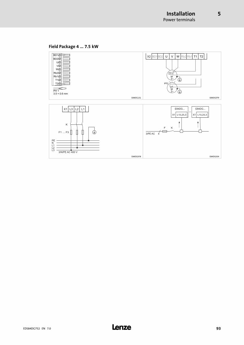
InstallationPower terminals
5
� 93EDS84DG752 EN 7.0
Field Package 4�...�7.5�kW
X2 Rb1Rb2U V W T1 T2BD2BD1
M3~
M3~
�
�PTCPTC
��
U V W T1 T2
E84DG131 E84DG079
X1
3/N/PE AC 400 V
L1L2L3
NPE
F1 … F3
K
�
L3 L2 L1
3/PE AC
E84DG...
X1 L1/L2/L3
4
...
KF
E84DG...
X1 L1/L2/L3
E84DG078 E84DG034

InstallationControl terminalsBasic I/O
5
� 94 EDS84DG752 EN 7.0
5.9 Control terminals
5.9.1 Basic I/O
Terminals
Mode Features Position of M12 plug
Basic I/OE84DGFCNNNP
Controller enable RFR 1A1
A2
A3
A4
B4
B3
B2
B1
Digital inputs DIx 2
Digital outputs DOx ˘
Analog inputs AU/AI ˘
Relay NO 1
STO safety function STO ˘
External 24 V supply 24E ˘ E84DG126a
S1
1)
24 Vext.
+
-
2)
24
V in
t.
100 mA
3.3
k
3.3
k
3.3
k
DI1
DI2
GN
D
GN
D
GN
D
RF
R
X4
CO
M
NO
n.c.
n.c.
n.c.
24O
24O
24O
E84DG016
1) External alternative voltage supply2) Wire jumper for permanent controller enable (delivery state)

InstallationControl terminals
Standard I/O
5
� 95EDS84DG752 EN 7.0
5.9.2 Standard I/O
Terminals
Mode Features Position of M12 plug
Standard I/OE84DGFCSNNP
Controller enable RFR 1A1
A2
A3
A4
B4
B3
B2
B1
Digital inputs DIx 5
Digital outputs DOx 1
Analog inputs AU/AI 1
Relay NO 1
STO safety function STO ˘
External 24 V supply 24E ˘ E84DG126a
S1 24 Vext.
+
-
2k ... 1
0k
0 ... 10 V / 0/4 ... 20 mA 1)
2)
3.3
k
3.3
k
3.3
k
3.3
k
3.3
k
3.3
k
+10 V/5 mA
DI1
DI2
DI3
DI4
DI5
DO
1
RF
R
X4
GN
D
AU
/AI
AR
CO
M
NO
n.c.
n.c.
24
V int.
100 mA
24O
24O
GN
D
GN
D
X3
n.c.
n.c.
n.c.
E84DG015a
1) External alternative voltage supply2) Wire jumper for permanent controller enable (delivery state)

InstallationControl terminalsExtended I/O
5
� 96 EDS84DG752 EN 7.0
5.9.3 Extended I/O
Terminals
Mode Features Position of M12 plug
Extended I/OE84DGFCXNNP
Controller enable RFR 1A1
A2
A3
A4
B4
B3
B2
B1
Digital inputs DIx 8
Digital outputs DOx 1
Analog inputs AxU 2
Relay NO 1
STO safety function STO ˘
External 24 V supply 24E ˘ E84DG126a
+10 V/5 mA
A2U
GA
GA
A1U
AR
X5
-10
... +
10
V
2k ... 1
0k
�
2k ... 1
0k
S1
1)
24 Vext.
+
-
2)
3.3
k
3.3
k
3.3
k
3.3
k
3.3
k
3.3
k
3.3
k
3.3
k
3.3
kD
I1
DI2
DI3
DI4
DI5
DI6
DI7
DI8
DO
1
RF
R
X4
CO
M
NO
n.c.
n.c.
24O
24O
24O
GN
D
X3
GN
D
GN
D
GN
D
24
V in
t.
100 mA
10
0 m
A
E84DG0115
1) External alternative voltage supply2) Wire jumper for permanent controller enable (delivery state)

InstallationControl terminals
AS−Interface
5
� 97EDS84DG752 EN 7.0
5.9.4 AS−Interface
Terminals
Mode Features Position of M12 plug
AS interfaceE84DGFCAFNP
Controller enable RFR 1A1
A2
A3
A4
LED
Bus
DI1/DI2
B4
B3
B2
B1
Digital inputs DIx 5
Digital outputs DOx 1
Analog inputs AU/AI ˘
Relay NO ˘
STO safety function STO ˘
External 24 V supply 24E ˘ E84DG126c
Mode Features Position of M12 plug
AS interfaceEnhancedE84DGFCAENP
Controller enable RFR 1A1
A2
A3
A4
LED
Bus
DI1/DI2
DI3/DO1 B4
B3
B2
B1
Digital inputs DIx 5
Digital outputs DOx 1
Analog inputs AU/AI ˘
Relay NO ˘
STO safety function STO ˘
External 24 V supply 24E ˘ E84DG126g
S1 24 Vext.
+
-
1)
3.3
k
3.3
k
3.3
k
3.3
k
3.3
k
3.3
k
24 V
int.
100 mA
DI1
DI2
DI3
DI4
DI5
DO
1
RF
R
X4
n.c.
n.c.
n.c.
n.c.
n.c.
n.c.
n.c.
24O
24O
GN
D
GN
D
X3
AS
- i+
AS
- i-
n.c.
E84DG015b
1) External alternative voltage supply2) Wire jumper for permanent controller enable (delivery state)
Assignment of M12 plug
A2 Assignment
2
4
5
3
1 1 ASI IN
2 n.�c.
3 ASI OUTM12 male socketA−coding
4 n.�c.
5 n.�c.
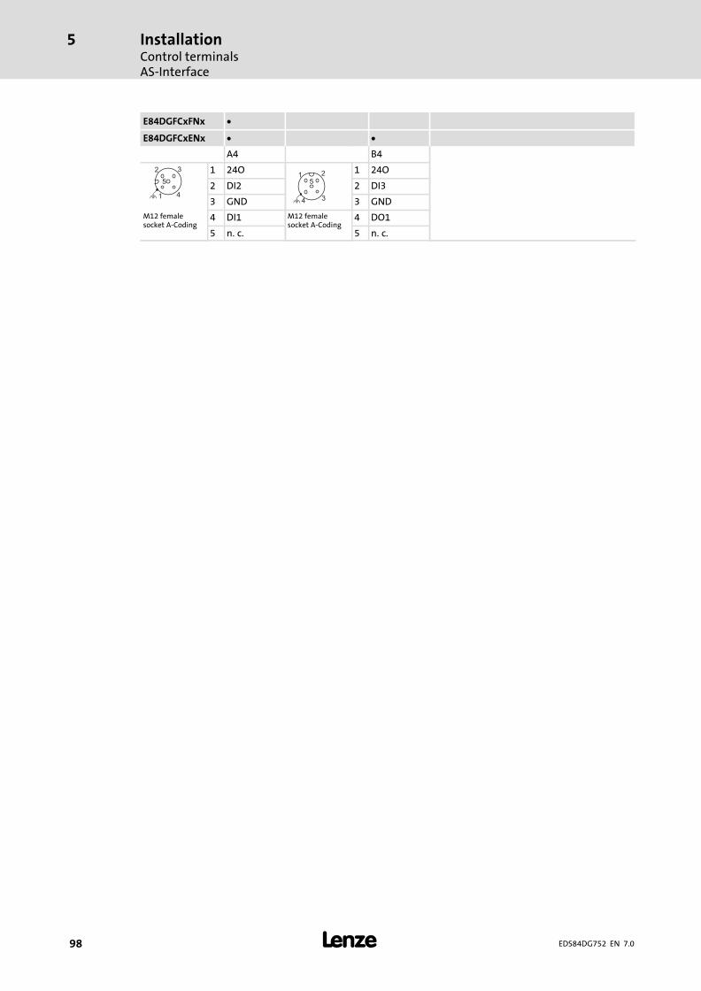
InstallationControl terminalsAS−Interface
5
� 98 EDS84DG752 EN 7.0
E84DGFCxFNx
E84DGFCxENx
A4 B4
2
4
5
3
1
1 24O5
4
1 2
3
1 24O
2 DI2 2 DI3
3 GND 3 GNDM12 femalesocket A−Coding
4 DI1 M12 femalesocket A−Coding
4 DO1
5 n.�c. 5 n.�c.
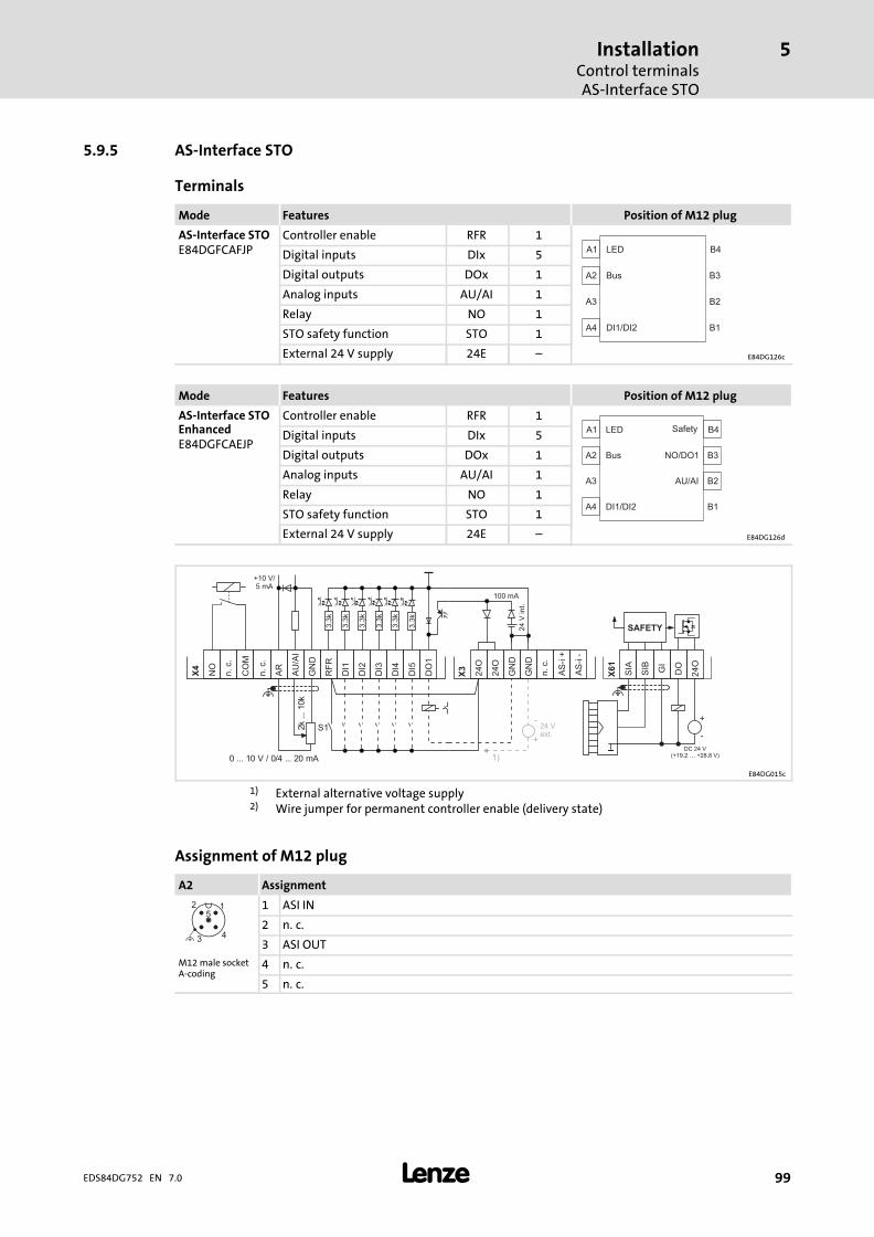
InstallationControl terminalsAS−Interface STO
5
� 99EDS84DG752 EN 7.0
5.9.5 AS−Interface STO
Terminals
Mode Features Position of M12 plug
AS−Interface STOE84DGFCAFJP
Controller enable RFR 1A1
A2
A3
A4
LED
Bus
DI1/DI2
B4
B3
B2
B1
Digital inputs DIx 5
Digital outputs DOx 1
Analog inputs AU/AI 1
Relay NO 1
STO safety function STO 1
External 24 V supply 24E ˘ E84DG126c
Mode Features Position of M12 plug
AS−Interface STOEnhancedE84DGFCAEJP
Controller enable RFR 1A1
A2
A3
A4
LED
Bus
DI1/DI2
Safety
NO/DO1
AU/AI
B4
B3
B2
B1
Digital inputs DIx 5
Digital outputs DOx 1
Analog inputs AU/AI 1
Relay NO 1
STO safety function STO 1
External 24 V supply 24E ˘ E84DG126d
DC 24 V(+19.2 … +28.8 V)
+
-
SAFETY
X61
SIB GI
SIA
DO
24
O
S1 24 Vext.
+
-
2k ... 1
0k
0 ... 10 V / 0/4 ... 20 mA 1)
3.3
k
3.3
k
3.3
k
3.3
k
3.3
k
3.3
k
+10 V/5 mA
DI1
DI2
DI3
DI4
DI5
DO
1
RF
R
X4
GN
D
AU
/AI
AR
CO
M
NO
n.c.
n.c.
24 V
int.
100 mA
24O
24O
GN
D
GN
D
X3
AS
- i+
AS
- i-
n.c.
E84DG015c
1) External alternative voltage supply2) Wire jumper for permanent controller enable (delivery state)
Assignment of M12 plug
A2 Assignment
2
4
5
3
1 1 ASI IN
2 n.�c.
3 ASI OUTM12 male socketA−coding
4 n.�c.
5 n.�c.

InstallationControl terminalsAS−Interface STO
5
� 100 EDS84DG752 EN 7.0
E84DGFCxFJx
E84DGFCxEJx
A4 B2 B3 B4
2
4
5
3
1
1 24O5
4
1 2
3
1 24O 24O 2
4
53
1
1 SIA
2 DI2 2 AU/AI DO1 2 SIB
3 GND 3 GND GND 3 DOM12 femalesocket A−Coding
4 DI1 M12 femalesocket A−Coding
4 AR COM M12 male socketA−Coding
4 24O
5 n.�c. 5 n.�c. NO 5 GI
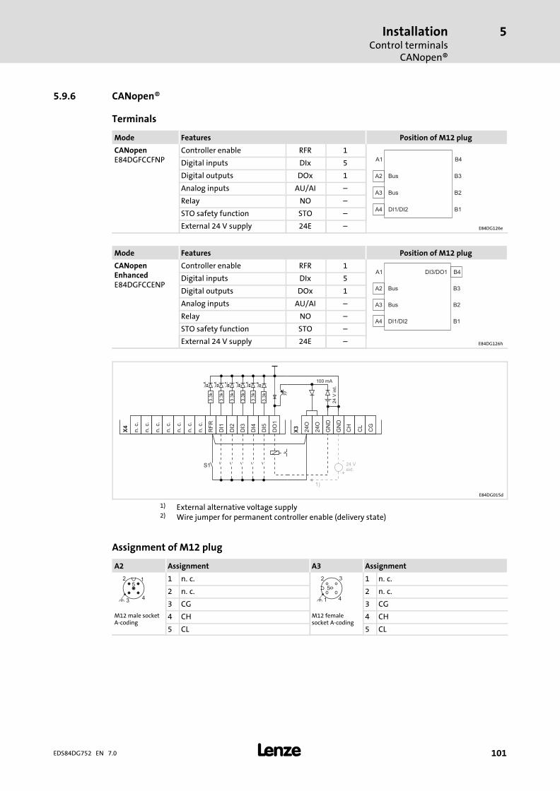
InstallationControl terminals
CANopen®
5
� 101EDS84DG752 EN 7.0
5.9.6 CANopen®
Terminals
Mode Features Position of M12 plug
CANopenE84DGFCCFNP
Controller enable RFR 1A1
A2
A3
A4
Bus
Bus
DI1/DI2
B4
B3
B2
B1
Digital inputs DIx 5
Digital outputs DOx 1
Analog inputs AU/AI ˘
Relay NO ˘
STO safety function STO ˘
External 24 V supply 24E ˘ E84DG126e
Mode Features Position of M12 plug
CANopenEnhancedE84DGFCCENP
Controller enable RFR 1A1
A2
A3
A4
Bus
DI1/DI2
DI3/DO1
Bus
B4
B3
B2
B1
Digital inputs DIx 5
Digital outputs DOx 1
Analog inputs AU/AI ˘
Relay NO ˘
STO safety function STO ˘
External 24 V supply 24E ˘ E84DG126h
S1 24 Vext.
+
-
1)
3.3
k
3.3
k
3.3
k
3.3
k
3.3
k
3.3
k
24 V
int.
100 mA
DI1
DI2
DI3
DI4
DI5
DO
1
RF
R
X4
n.c.
n.c.
n.c.
n.c.
n.c.
n.c.
n.c.
24O
24O
GN
D
GN
D
X3
CL
CG
CH
E84DG015d
1) External alternative voltage supply2) Wire jumper for permanent controller enable (delivery state)
Assignment of M12 plug
A2 Assignment A3 Assignment
2
4
5
3
1 1 n.�c. 2
4
5
3
1
1 n.�c.
2 n.�c. 2 n.�c.
3 CG 3 CGM12 male socketA−coding
4 CH M12 femalesocket A−coding
4 CH
5 CL 5 CL

InstallationControl terminalsCANopen®
5
� 102 EDS84DG752 EN 7.0
E84DGFCxFNx
E84DGFCxENx
A4 B4
2
4
5
3
1
1 24O5
4
1 2
3
1 24O
2 DI2 2 DI3
3 GND 3 GNDM12 femalesocket A−Coding
4 DI1 M12 femalesocket A−Coding
4 DO1
5 n.�c. 5 n.�c.
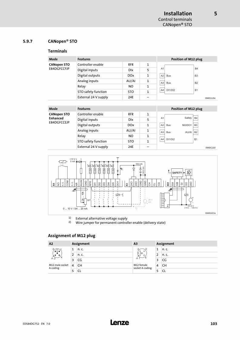
InstallationControl terminals
CANopen® STO
5
� 103EDS84DG752 EN 7.0
5.9.7 CANopen® STO
Terminals
Mode Features Position of M12 plug
CANopen STOE84DGFCCFJP
Controller enable RFR 1A1
A2
A3
A4
Bus
Bus
DI1/DI2
B4
B3
B2
B1
Digital inputs DIx 5
Digital outputs DOx 1
Analog inputs AU/AI 1
Relay NO 1
STO safety function STO 1
External 24 V supply 24E ˘ E84DG126e
Mode Features Position of M12 plug
CANopen STOEnhancedE84DGFCCEJP
Controller enable RFR 1A1
A2
A3
A4
B4
B3
B2
B1
Bus
DI1/DI2
AU/AIBus
Safety
NO/DO1
Digital inputs DIx 5
Digital outputs DOx 1
Analog inputs AU/AI 1
Relay NO 1
STO safety function STO 1
External 24 V supply 24E ˘ E84DG126i
DC 24 V(+19.2 … +28.8 V)
+
-
SAFETY
X61
SIB GI
SIA
DO
24
O
S1 24 Vext.
+
-
2k ... 1
0k
0 ... 10 V / 0/4 ... 20 mA 1)
3.3
k
3.3
k
3.3
k
3.3
k
3.3
k
3.3
k
+10 V/5 mA
DI1
DI2
DI3
DI4
DI5
DO
1
RF
R
X4
GN
D
AU
/AI
AR
CO
M
NO
n.c.
n.c.
24 V
int.
100 mA
24O
24O
GN
D
GN
D
X3
CL
CG
CH
E84DG015e
1) External alternative voltage supply2) Wire jumper for permanent controller enable (delivery state)
Assignment of M12 plug
A2 Assignment A3 Assignment
2
4
5
3
1 1 n.�c. 2
4
5
3
1
1 n.�c.
2 n.�c. 2 n.�c.
3 CG 3 CGM12 male socketA−coding
4 CH M12 femalesocket A−coding
4 CH
5 CL 5 CL

InstallationControl terminalsCANopen® STO
5
� 104 EDS84DG752 EN 7.0
E84DGFCxFJx
E84DGFCxEJx
A4 B2 B3 B4
2
4
5
3
1
1 24O5
4
1 2
3
1 24O 24O 2
4
53
1
1 SIA
2 DI2 2 AU/AI DO1 2 SIB
3 GND 3 GND GND 3 DOM12 femalesocket A−Coding
4 DI1 M12 femalesocket A−Coding
4 AR COM M12 male socketA−Coding
4 24O
5 n.�c. 5 n.�c. NO 5 GI

InstallationControl terminals
EtherCAT®
5
� 105EDS84DG752 EN 7.0
5.9.8 EtherCAT®
Terminals
Mode Features Position of M12 plug
EtherCATE84DGFCTFNP
Controller enable RFR 1A1
A2
A3
A4
LED
Bus
DI1/DI2
Bus
B4
B3
B2
B1
Digital inputs DIx 5
Digital outputs DOx 1
Analog inputs AU/AI ˘
Relay NO ˘
STO safety function STO ˘
External 24 V supply 24E 1 E84DG126f
Mode Features Position of M12 plug
EtherCATEnhancedE84DGFCTENP
Controller enable RFR 1A1
A2
A3
A4
LED B4
B3
B2
B1
Bus
DI1/DI2
Bus
DI3/DO1
Digital inputs DIx 5
Digital outputs DOx 1
Analog inputs AU/AI ˘
Relay NO ˘
STO safety function STO ˘
External 24 V supply 24E 1 E84DG126j
S1 24 Vext.
+
-24 Vext.
-24 Vext.
-
+
1)
3.3
k
3.3
k
3.3
k
3.3
k
3.3
k
3.3
k
24 V
int.
100 mA
DI1
DI2
DI3
DI4
DI5
DO
1
RF
R
X4
n.c.
n.c.
n.c.
n.c.
n.c.
n.c.
n.c.
24O
24O
GN
D
GN
D
X3
24E
GN
D
n.c.
X31
X32
E84DG015f
1) External alternative voltage supply2) Wire jumper for permanent controller enable (delivery state)
Assignment of M12 plug
A2 Assignment A3 Assignment
4
1
23
1 TX+
4
1
23
1 TX+
2 Rx+ 2 Rx+
3 Tx − 3 Tx −M12 femalesocket D−coding
4 RX− M12 femalesocket D−coding
4 RX−
5 Contact plate 5 Contact plate

InstallationControl terminalsEtherCAT®
5
� 106 EDS84DG752 EN 7.0
E84DGFCxFNx
E84DGFCxENx
A4 B4
2
4
5
3
1
1 24O5
4
1 2
3
1 24O
2 DI2 2 DI3
3 GND 3 GNDM12 femalesocket A−Coding
4 DI1 M12 femalesocket A−Coding
4 DO1
5 n.�c. 5 n.�c.

InstallationControl terminals
EtherCAT® STO
5
� 107EDS84DG752 EN 7.0
5.9.9 EtherCAT® STO
Terminals
Mode Features Position of M12 plug
EtherCAT STOE84DGFCTFJP
Controller enable RFR 1A1
A2
A3
A4
LED
Bus
DI1/DI2
Bus
B4
B3
B2
B1
Digital inputs DIx 5
Digital outputs DOx 1
Analog inputs AU/AI 1
Relay NO 1
STO safety function STO 1
External 24 V supply 24E 1 E84DG126f
Mode Features Position of M12 plug
EtherCAT STOEnhancedE84DGFCTEJP
Controller enable RFR 1A1
A2
A3
A4
LED
Bus
DI1/DI2
Bus
Safety
NO/DO1
AU/AI
B4
B3
B2
B1
Digital inputs DIx 5
Digital outputs DOx 1
Analog inputs AU/AI 1
Relay NO 1
STO safety function STO 1
External 24 V supply 24E 1 E84DG126b
DC 24 V(+19.2 … +28.8 V)
+
-
SAFETY
X61
SIB GI
SIA
DO
24
O
S1 24 Vext.
+
-
2k ... 1
0k
0 ... 10 V / 0/4 ... 20 mA 1)
24 Vext.
-
+
3.3
k
3.3
k
3.3
k
3.3
k
3.3
k
3.3
k
+10 V/5 mA
DI1
DI2
DI3
DI4
DI5
DO
1
RF
R
X4
GN
D
AU
/AI
AR
CO
M
NO
n.c.
n.c.
24 V
int.
100 mA
24O
24O
GN
D
GN
D
X3
24E
GN
D
n.c.
X31
X32
E84DG015g
1) External alternative voltage supply2) Wire jumper for permanent controller enable (delivery state)
Assignment of M12 plug
A2 Assignment A3 Assignment
4
1
23
1 TX+
4
1
23
1 TX+
2 Rx+ 2 Rx+
3 Tx − 3 Tx −M12 femalesocket D−coding
4 RX− M12 femalesocket D−coding
4 RX−
5 Contact plate 5 Contact plate

InstallationControl terminalsEtherCAT® STO
5
� 108 EDS84DG752 EN 7.0
E84DGFCxFJx
E84DGFCxEJx
A4 B2 B3 B4
2
4
5
3
1
1 24O5
4
1 2
3
1 24O 24O 2
4
53
1
1 SIA
2 DI2 2 AU/AI DO1 2 SIB
3 GND 3 GND GND 3 DOM12 femalesocket A−Coding
4 DI1 M12 femalesocket A−Coding
4 AR COM M12 male socketA−Coding
4 24O
5 n.�c. 5 n.�c. NO 5 GI

InstallationControl terminals
EtherNet/IP�
5
� 109EDS84DG752 EN 7.0
5.9.10 EtherNet/IP�
Terminals
Mode Features Position of M12 plug
EtherNet/IPE84DGFCGFNP
Controller enable RFR 1A1
A2
A3
A4
LED
Bus
DI1/DI2
Bus
B4
B3
B2
B1
Digital inputs DIx 5
Digital outputs DOx 1
Analog inputs AU/AI ˘
Relay NO ˘
STO safety function STO ˘
External 24 V supply 24E 1 E84DG126f
Mode Features Position of M12 plug
EtherNet/IPEnhancedE84DGFCGENP
Controller enable RFR 1A1
A2
A3
A4
LED B4
B3
B2
B1
Bus
DI1/DI2
Bus
DI3/DO1Digital inputs DIx 5
Digital outputs DOx 1
Analog inputs AU/AI ˘
Relay NO ˘
STO safety function STO ˘
External 24 V supply 24E 1 E84DG126j
S1 24 Vext.
+
-24 Vext.
-24 Vext.
-
+
1)
3.3
k
3.3
k
3.3
k
3.3
k
3.3
k
3.3
k
24 V
int.
100 mA
DI1
DI2
DI3
DI4
DI5
DO
1
RF
R
X4
n.c.
n.c.
n.c.
n.c.
n.c.
n.c.
n.c.
24O
24O
GN
D
GN
D
X3
24E
GN
D
n.c.
X31
X32
E84DG015f
1) External alternative voltage supply2) Wire jumper for permanent controller enable (delivery state)
Assignment of M12 plug
A2 Assignment A3 Assignment
4
1
23
1 TX+
4
1
23
1 TX+
2 Rx+ 2 Rx+
3 Tx − 3 Tx −M12 femalesocket D−coding
4 RX− M12 femalesocket D−coding
4 RX−
5 Contact plate 5 Contact plate

InstallationControl terminalsEtherNet/IP�
5
� 110 EDS84DG752 EN 7.0
E84DGFCxFNx
E84DGFCxENx
A4 B4
2
4
5
3
1
1 24O5
4
1 2
3
1 24O
2 DI2 2 DI3
3 GND 3 GNDM12 femalesocket A−Coding
4 DI1 M12 femalesocket A−Coding
4 DO1
5 n.�c. 5 n.�c.

InstallationControl terminalsEtherNet/IP� STO
5
� 111EDS84DG752 EN 7.0
5.9.11 EtherNet/IP� STO
Terminals
Mode Features Position of M12 plug
EtherNET/IP STOE84DGFCGFJP
Controller enable RFR 1A1
A2
A3
A4
LED
Bus
DI1/DI2
Bus
B4
B3
B2
B1
Digital inputs DIx 5
Digital outputs DOx 1
Analog inputs AU/AI 1
Relay NO 1
STO safety function STO 1
External 24 V supply 24E 1 E84DG126f
Mode Features Position of M12 plug
EtherNET/IP STOEnhancedE84DGFCGEJP
Controller enable RFR 1A1
A2
A3
A4
LED
Bus
DI1/DI2
Bus
Safety
NO/DO1
AU/AI
B4
B3
B2
B1
Digital inputs DIx 5
Digital outputs DOx 1
Analog inputs AU/AI 1
Relay NO 1
STO safety function STO 1
External 24 V supply 24E 1 E84DG126b
DC 24 V(+19.2 … +28.8 V)
+
-
SAFETY
X61
SIB GI
SIA
DO
24
O
S1 24 Vext.
+
-
2k ... 1
0k
0 ... 10 V / 0/4 ... 20 mA 1)
24 Vext.
-
+
3.3
k
3.3
k
3.3
k
3.3
k
3.3
k
3.3
k
+10 V/5 mA
DI1
DI2
DI3
DI4
DI5
DO
1
RF
R
X4
GN
D
AU
/AI
AR
CO
M
NO
n.c.
n.c.
24 V
int.
100 mA
24O
24O
GN
D
GN
D
X3
24E
GN
D
n.c.
X31
X32
E84DG015g
1) External alternative voltage supply2) Wire jumper for permanent controller enable (delivery state)
Assignment of M12 plug
A2 Assignment A3 Assignment
4
1
23
1 TX+
4
1
23
1 TX+
2 Rx+ 2 Rx+
3 Tx − 3 Tx −M12 femalesocket D−coding
4 RX− M12 femalesocket D−coding
4 RX−
5 Contact plate 5 Contact plate
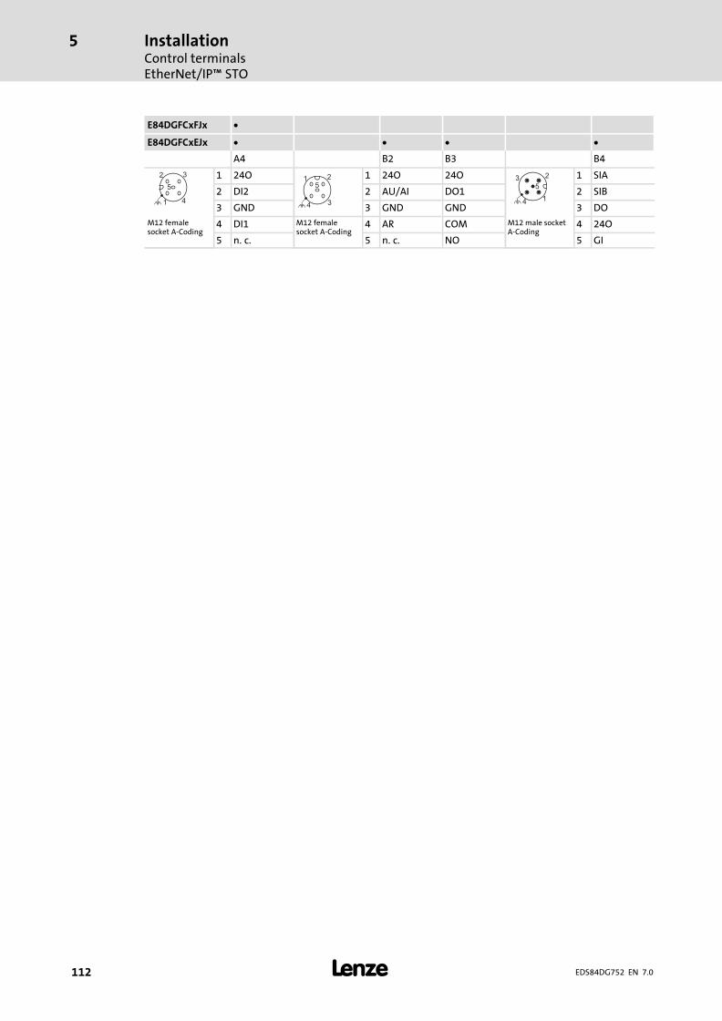
InstallationControl terminalsEtherNet/IP� STO
5
� 112 EDS84DG752 EN 7.0
E84DGFCxFJx
E84DGFCxEJx
A4 B2 B3 B4
2
4
5
3
1
1 24O5
4
1 2
3
1 24O 24O 2
4
53
1
1 SIA
2 DI2 2 AU/AI DO1 2 SIB
3 GND 3 GND GND 3 DOM12 femalesocket A−Coding
4 DI1 M12 femalesocket A−Coding
4 AR COM M12 male socketA−Coding
4 24O
5 n.�c. 5 n.�c. NO 5 GI
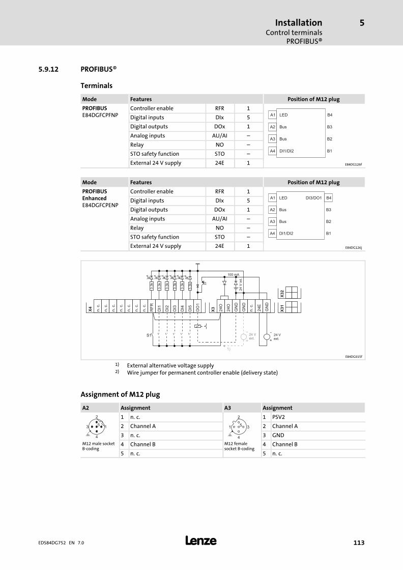
InstallationControl terminals
PROFIBUS®
5
� 113EDS84DG752 EN 7.0
5.9.12 PROFIBUS®
Terminals
Mode Features Position of M12 plug
PROFIBUSE84DGFCPFNP
Controller enable RFR 1A1
A2
A3
A4
LED
Bus
DI1/DI2
Bus
B4
B3
B2
B1
Digital inputs DIx 5
Digital outputs DOx 1
Analog inputs AU/AI ˘
Relay NO ˘
STO safety function STO ˘
External 24 V supply 24E 1 E84DG126f
Mode Features Position of M12 plug
PROFIBUSEnhancedE84DGFCPENP
Controller enable RFR 1A1
A2
A3
A4
LED B4
B3
B2
B1
Bus
DI1/DI2
Bus
DI3/DO1Digital inputs DIx 5
Digital outputs DOx 1
Analog inputs AU/AI ˘
Relay NO ˘
STO safety function STO ˘
External 24 V supply 24E 1 E84DG126j
S1 24 Vext.
+
-24 Vext.
-24 Vext.
-
+
1)
3.3
k
3.3
k
3.3
k
3.3
k
3.3
k
3.3
k
24 V
int.
100 mA
DI1
DI2
DI3
DI4
DI5
DO
1
RF
R
X4
n.c.
n.c.
n.c.
n.c.
n.c.
n.c.
n.c.
24O
24O
GN
D
GN
D
X3
24E
GN
D
n.c.
X31
X32
E84DG015f
1) External alternative voltage supply2) Wire jumper for permanent controller enable (delivery state)
Assignment of M12 plug
A2 Assignment A3 Assignment
2
4
53 1
1 n.�c.
1
2
3
4
5
1 PSV2
2 Channel A 2 Channel A
3 n.�c. 3 GNDM12 male socketB−coding
4 Channel B M12 femalesocket B−coding
4 Channel B
5 n.�c. 5 n.�c.
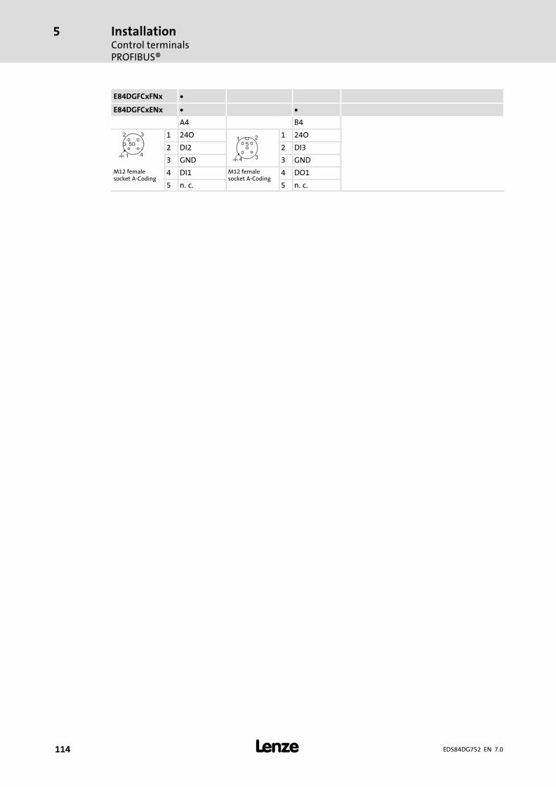
InstallationControl terminalsPROFIBUS®
5
� 114 EDS84DG752 EN 7.0
E84DGFCxFNx
E84DGFCxENx
A4 B4
2
4
5
3
1
1 24O5
4
1 2
3
1 24O
2 DI2 2 DI3
3 GND 3 GNDM12 femalesocket A−Coding
4 DI1 M12 femalesocket A−Coding
4 DO1
5 n.�c. 5 n.�c.

InstallationControl terminals
PROFIBUS® STO
5
� 115EDS84DG752 EN 7.0
5.9.13 PROFIBUS® STO
Terminals
Mode Features Position of M12 plug
PROFIBUS STOE84DGFCPFJP
Controller enable RFR 1A1
A2
A3
A4
LED
Bus
DI1/DI2
Bus
B4
B3
B2
B1
Digital inputs DIx 5
Digital outputs DOx 1
Analog inputs AU/AI 1
Relay NO 1
STO safety function STO 1
External 24 V supply 24E 1 E84DG126f
Mode Features Position of M12 plug
PROFIBUS STOEnhancedE84DGFCPEJP
Controller enable RFR 1A1
A2
A3
A4
LED
Bus
DI1/DI2
Bus
Safety
NO/DO1
AU/AI
B4
B3
B2
B1
Digital inputs DIx 5
Digital outputs DOx 1
Analog inputs AU/AI 1
Relay NO 1
STO safety function STO 1
External 24 V supply 24E 1 E84DG126b
DC 24 V(+19.2 … +28.8 V)
+
-
SAFETY
X61
SIB GI
SIA
DO
24
O
S1 24 Vext.
+
-
2k ... 1
0k
0 ... 10 V / 0/4 ... 20 mA 1)
24 Vext.
-
+
3.3
k
3.3
k
3.3
k
3.3
k
3.3
k
3.3
k
+10 V/5 mA
DI1
DI2
DI3
DI4
DI5
DO
1
RF
R
X4
GN
D
AU
/AI
AR
CO
M
NO
n.c.
n.c.
24 V
int.
100 mA
24O
24O
GN
D
GN
D
X3
24E
GN
D
n.c.
X31
X32
E84DG015g
1) External alternative voltage supply2) Wire jumper for permanent controller enable (delivery state)
Assignment of M12 plug
A2 Assignment A3 Assignment
2
4
53 1
1 n.�c.
1
2
3
4
5
1 PSV2
2 Channel A 2 Channel A
3 n.�c. 3 GNDM12 male socketB−coding
4 Channel B M12 femalesocket B−coding
4 Channel B
5 n.�c. 5 n.�c.

InstallationControl terminalsPROFIBUS® STO
5
� 116 EDS84DG752 EN 7.0
E84DGFCxFJx
E84DGFCxEJx
A4 B2 B3 B4
2
4
5
3
1
1 24O5
4
1 2
3
1 24O 24O 2
4
53
1
1 SIA
2 DI2 2 AU/AI DO1 2 SIB
3 GND 3 GND GND 3 DOM12 femalesocket A−Coding
4 DI1 M12 femalesocket A−Coding
4 AR COM M12 male socketA−Coding
4 24O
5 n.�c. 5 n.�c. NO 5 GI
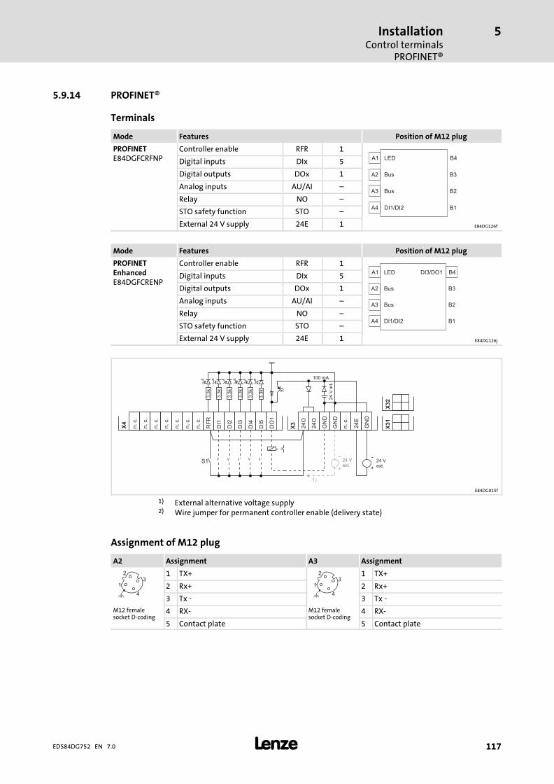
InstallationControl terminals
PROFINET®
5
� 117EDS84DG752 EN 7.0
5.9.14 PROFINET®
Terminals
Mode Features Position of M12 plug
PROFINETE84DGFCRFNP
Controller enable RFR 1A1
A2
A3
A4
LED
Bus
DI1/DI2
Bus
B4
B3
B2
B1
Digital inputs DIx 5
Digital outputs DOx 1
Analog inputs AU/AI ˘
Relay NO ˘
STO safety function STO ˘
External 24 V supply 24E 1 E84DG126f
Mode Features Position of M12 plug
PROFINETEnhancedE84DGFCRENP
Controller enable RFR 1A1
A2
A3
A4
LED B4
B3
B2
B1
Bus
DI1/DI2
Bus
DI3/DO1Digital inputs DIx 5
Digital outputs DOx 1
Analog inputs AU/AI ˘
Relay NO ˘
STO safety function STO ˘
External 24 V supply 24E 1 E84DG126j
S1 24 Vext.
+
-24 Vext.
-24 Vext.
-
+
1)
3.3
k
3.3
k
3.3
k
3.3
k
3.3
k
3.3
k
24 V
int.
100 mA
DI1
DI2
DI3
DI4
DI5
DO
1
RF
R
X4
n.c.
n.c.
n.c.
n.c.
n.c.
n.c.
n.c.
24O
24O
GN
D
GN
D
X3
24E
GN
D
n.c.
X31
X32
E84DG015f
1) External alternative voltage supply2) Wire jumper for permanent controller enable (delivery state)
Assignment of M12 plug
A2 Assignment A3 Assignment
4
1
23
1 TX+
4
1
23
1 TX+
2 Rx+ 2 Rx+
3 Tx − 3 Tx −M12 femalesocket D−coding
4 RX− M12 femalesocket D−coding
4 RX−
5 Contact plate 5 Contact plate

InstallationControl terminalsPROFINET®
5
� 118 EDS84DG752 EN 7.0
E84DGFCxFNx
E84DGFCxENx
A4 B4
2
4
5
3
1
1 24O5
4
1 2
3
1 24O
2 DI2 2 DI3
3 GND 3 GNDM12 femalesocket A−Coding
4 DI1 M12 femalesocket A−Coding
4 DO1
5 n.�c. 5 n.�c.
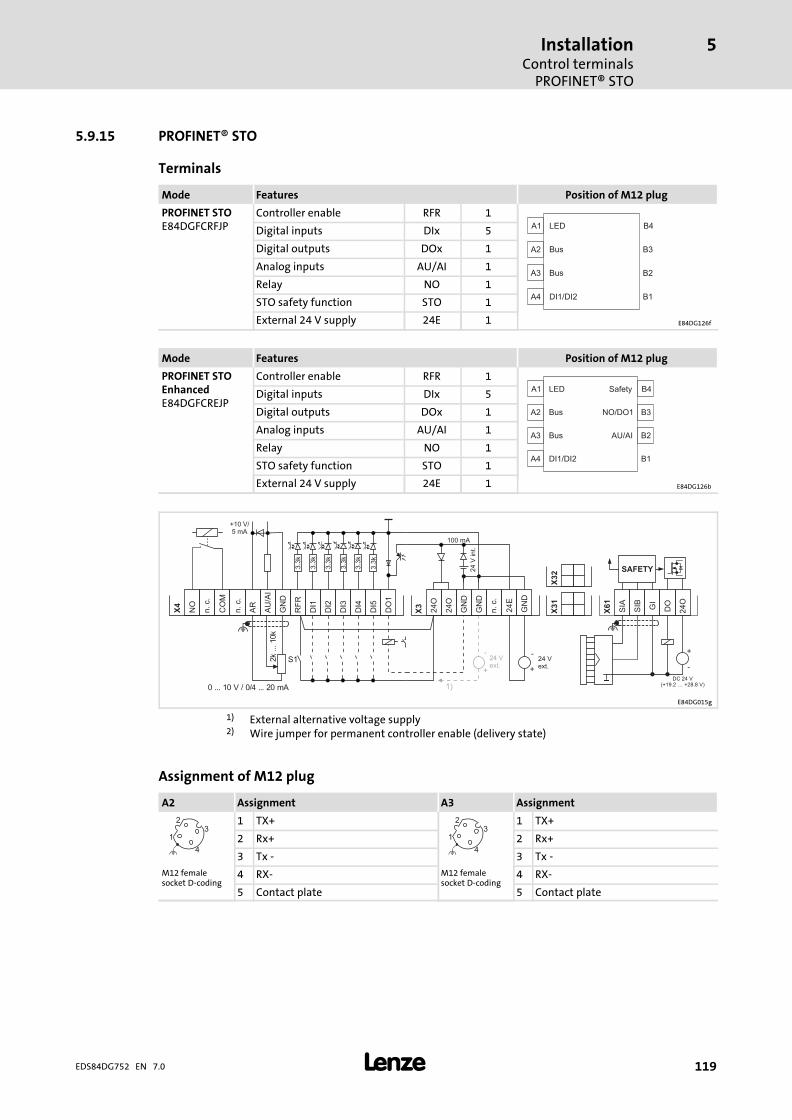
InstallationControl terminals
PROFINET® STO
5
� 119EDS84DG752 EN 7.0
5.9.15 PROFINET® STO
Terminals
Mode Features Position of M12 plug
PROFINET STOE84DGFCRFJP
Controller enable RFR 1A1
A2
A3
A4
LED
Bus
DI1/DI2
Bus
B4
B3
B2
B1
Digital inputs DIx 5
Digital outputs DOx 1
Analog inputs AU/AI 1
Relay NO 1
STO safety function STO 1
External 24 V supply 24E 1 E84DG126f
Mode Features Position of M12 plug
PROFINET STOEnhancedE84DGFCREJP
Controller enable RFR 1A1
A2
A3
A4
LED
Bus
DI1/DI2
Bus
Safety
NO/DO1
AU/AI
B4
B3
B2
B1
Digital inputs DIx 5
Digital outputs DOx 1
Analog inputs AU/AI 1
Relay NO 1
STO safety function STO 1
External 24 V supply 24E 1 E84DG126b
DC 24 V(+19.2 … +28.8 V)
+
-
SAFETY
X61
SIB GI
SIA
DO
24
O
S1 24 Vext.
+
-
2k ... 1
0k
0 ... 10 V / 0/4 ... 20 mA 1)
24 Vext.
-
+
3.3
k
3.3
k
3.3
k
3.3
k
3.3
k
3.3
k
+10 V/5 mA
DI1
DI2
DI3
DI4
DI5
DO
1
RF
R
X4
GN
D
AU
/AI
AR
CO
M
NO
n.c.
n.c.
24 V
int.
100 mA
24O
24O
GN
D
GN
D
X3
24E
GN
D
n.c.
X31
X32
E84DG015g
1) External alternative voltage supply2) Wire jumper for permanent controller enable (delivery state)
Assignment of M12 plug
A2 Assignment A3 Assignment
4
1
23
1 TX+
4
1
23
1 TX+
2 Rx+ 2 Rx+
3 Tx − 3 Tx −M12 femalesocket D−coding
4 RX− M12 femalesocket D−coding
4 RX−
5 Contact plate 5 Contact plate

InstallationControl terminalsPROFINET® STO
5
� 120 EDS84DG752 EN 7.0
E84DGFCxFJx
E84DGFCxEJx
A4 B2 B3 B4
2
4
5
3
1
1 24O5
4
1 2
3
1 24O 24O 2
4
53
1
1 SIA
2 DI2 2 AU/AI DO1 2 SIB
3 GND 3 GND GND 3 DOM12 femalesocket A−Coding
4 DI1 M12 femalesocket A−Coding
4 AR COM M12 male socketA−Coding
4 24O
5 n.�c. 5 n.�c. NO 5 GI

CommissioningBefore you start
6
� 121EDS84DG752 EN 7.0
6 Commissioning
� Note!ƒ Please observe the general safety instructions (� 12).
ƒ Please observe the notes regarding residual hazards (� 18).
6.1 Before you start
Selection of the appropriate commissioning tool
� Tip!Use the »Engineer« to carry out extensive parameter setting andconfiguration. The online help which is available for each device and theaccompanying software documentation will assist you.
The 8400 motec keypad (diagnosis terminal version) can be used for quickcommissioning and checking individual parameters on the controller.
Low rotating field frequency with a self−ventilated motor
Danger!ƒ For thermal reasons, continuous operation of self−ventilated motors at low
field frequency and rated motor current is not permissible. If required,activate a motor temperature monitoring with C00585– motor temperature monitoring with I2xt (see software manual)– motor temperature monitoring with motor PTC (see software manual).
ƒ When setting the V/f base frequency (C00015), please observe the followingdifference to the 8400 StateLine/HighLine/TopLine controllers:
For the 8400 motec drive, the reference voltage for the V/f base frequency isthe rated motor voltage (C00090) according to the motor nameplate(independently of the line−side supply voltage).
Fan for 4�...�7.5�kW Drive Unit
� Note!If the heatsink temperature of the 4�...�7.5�kW Drive Unit exceeds apermanently defined limit value, the fans of the Drive Unit will switch onautomatically.
ƒ The limit value for the temperature monitoring function is defined in thedevice and cannot be parameterised.

CommissioningBefore you start
6
� 122 EDS84DG752 EN 7.0
� Tip!In the Lenze setting, the VFCplus motor control (V/f characteristic control) withlinear characteristic is set in C00006.
ƒ VFCplus is especially suitable for the operation of machines with a linear orsquare−law load torque characteristic (e.�g. fan).
ƒ The parameters are preset so that, with an inverter that is adapted in termsof power and a 50 Hz motor, the inverter is ready for operation withoutfurther parameterisation and the motor is working satisfactorily.
Recommendations for the following application cases:
ƒ Inverter and motor differing strongly in terms of power:– Set code C00022 (Imax limit in motor mode) to 2�×�Irated motor.
ƒ High starting torque:– Set code C00016 (Vmin boost) in no−load operation of the motor, so that
the rated motor current is flowing with a rotating field frequency f = 3 Hz(C00058).
ƒ Noise optimisation:– Set code C00018 to the value "3" (switching frequency 16 kHz).
ƒ High torque at low speeds (without feedback):– Select "Vector control" operating mode.
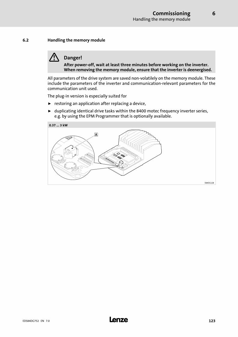
CommissioningHandling the memory module
6
� 123EDS84DG752 EN 7.0
6.2 Handling the memory module
� Danger!
After power−off, wait at least three minutes before working on the inverter.When removing the memory module, ensure that the inverter is deenergised.
All parameters of the drive system are saved non−volatilely on the memory module. Theseinclude the parameters of the inverter and communication−relevant parameters for thecommunication unit used.
The plug−in version is especially suited for
ƒ restoring an application after replacing a device,
ƒ duplicating identical drive tasks within the 8400 motec frequency inverter series,e.g. by using the EPM Programmer that is optionally available.
0.37�...�3�kW
E84DG128

CommissioningHandling the memory module
6
� 124 EDS84DG752 EN 7.0
4�...�7.5�kW
E84DG127
� Memory module, pluggable
� Note!
ƒ When the device is switched on, all parameters are automatically loadedfrom the memory module to the main memory of the inverter.– If DIP1/1 is in the ON position, the inverter works with the settings made
via DIP1 and DIP2 and shows these settings in the corresponding codes.
ƒ The 8400 BaseLine and 8400 motec inverters use the same (grey) memorymodule. The memory module can be shifted between these inverters,however, the corresponding inverter must be reparameterised afterwards.
When handling the memory module, a distinction is drawn between the followingscenarios:
Delivery status
ƒ The memory module is plugged into the EPM slot of the drive unit.
ƒ The Lenze setting of the parameters is stored in the memory module.
ƒ The memory module is available as a spare part ˘ without any data contents˘.
During operation
Parameter sets can be saved manually.
ƒ Parameter sets can be loaded manually.
ƒ Parameter changes can be saved automatically.

CommissioningCommissioning via DIP switch/potentiometer
6
� 125EDS84DG752 EN 7.0
6.3 Commissioning via DIP switch/potentiometer
Stop!
Automatic motor start
In "Local mode" The auto−start option "Inhibit at power−on" is not set. Whenthe mains is connected, the motor starts if the controller enable RFR is bridgedor set.
("Local mode" => DIP1/1 = ON and DIP2/5−7 = OFF)
Possible consequences:
ƒ Danger or damages through unexpected motor start.
Protective measures:
ƒ Decouple the motor from the drive train during commissioning phase.
ƒ Replace the factory−set bridge at RFR by an NO contact.
ƒ Do not set controller enable.
For initial commissioning, settings can be made via DIP switch and potentiometer. Thesettings must be made before mounting the drive unit since the setting elements cannotbe accessed from the outside.
From software version 07.00.00 onwards, you can use DIP2/8 to set two differentpre−assignments of DIP1, DIP2, P1, P2, and P3:
ƒ DIP2/8�=�OFF: DIP switch/ potentiometer assignment 0
ƒ DIP2/8�=�ON: DIP switch/ potentiometer assignment 1
Up to software version 07.00.00, only DIP switch/ potentiometer assignment 0 is available.
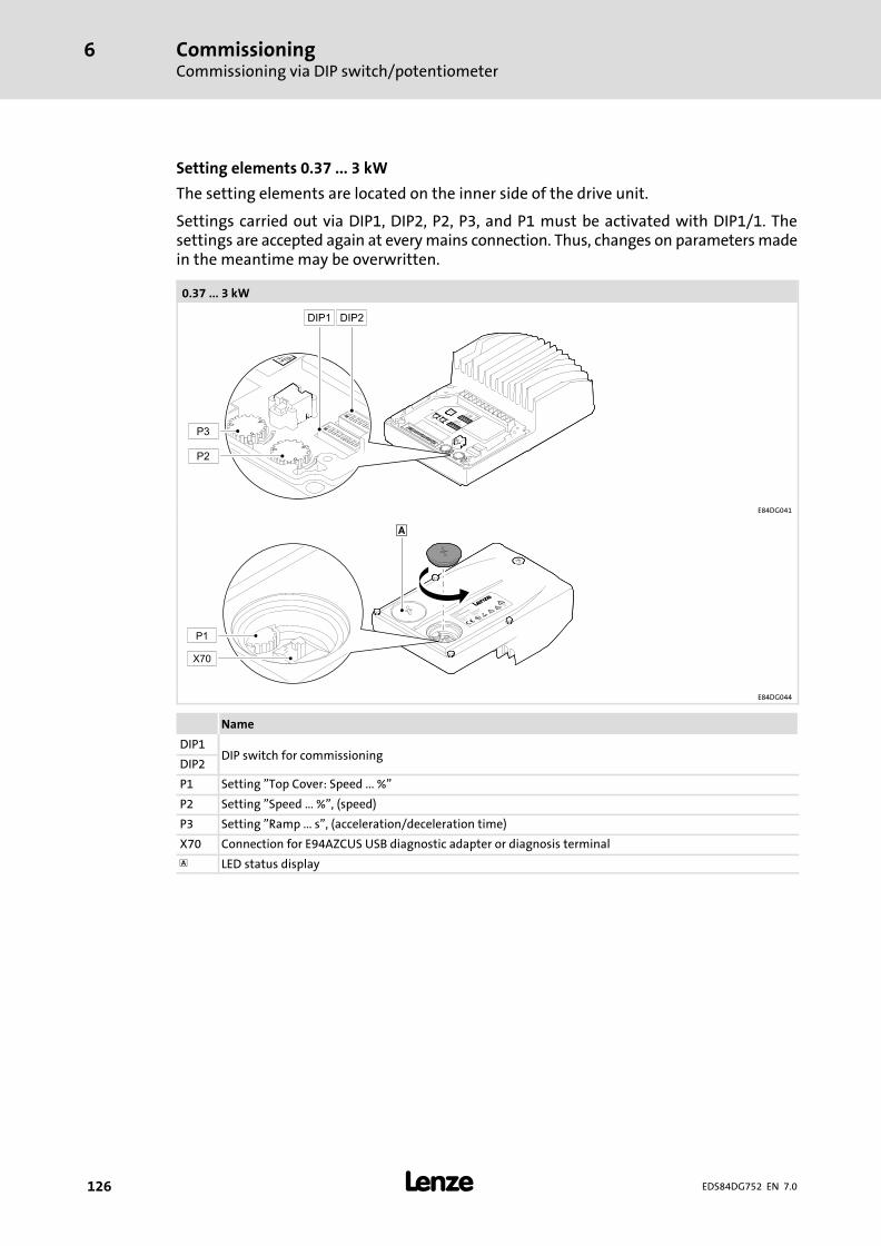
CommissioningCommissioning via DIP switch/potentiometer
6
� 126 EDS84DG752 EN 7.0
Setting elements 0.37 ... 3 kW
The setting elements are located on the inner side of the drive unit.
Settings carried out via DIP1, DIP2, P2, P3, and P1 must be activated with DIP1/1. Thesettings are accepted again at every mains connection. Thus, changes on parameters madein the meantime may be overwritten.
0.37 ... 3 kW
E84DG041
E84DG044
Name
DIP1DIP switch for commissioning
DIP2
P1 Setting "Top Cover: Speed ... %"
P2 Setting "Speed ... %", (speed)
P3 Setting "Ramp ... s", (acceleration/deceleration time)
X70 Connection for E94AZCUS USB diagnostic adapter or diagnosis terminal
� LED status display
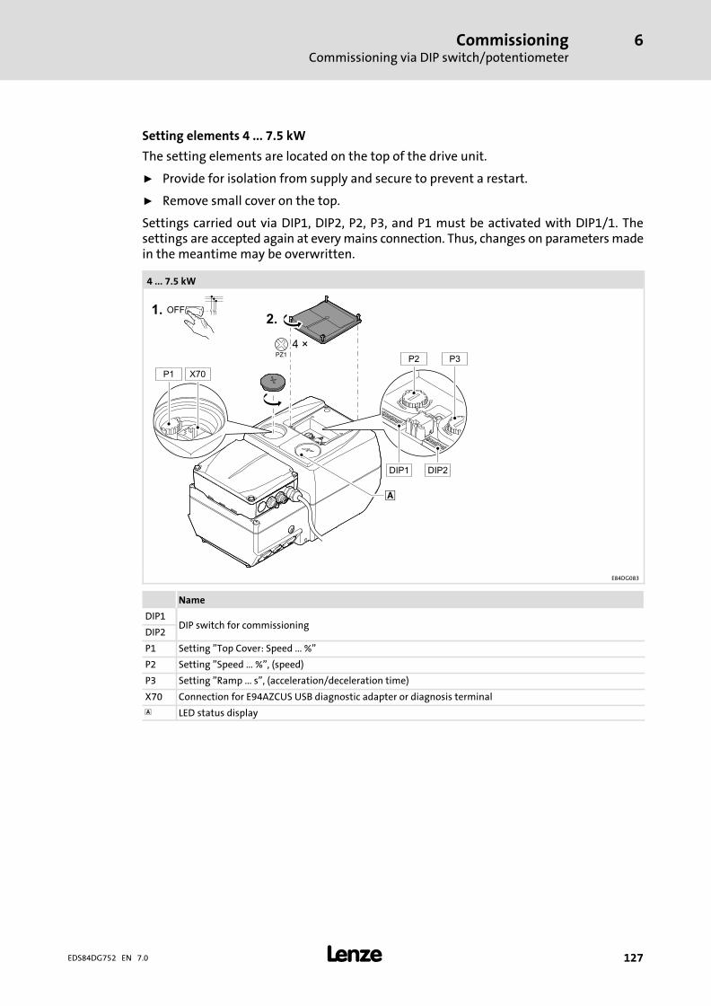
CommissioningCommissioning via DIP switch/potentiometer
6
� 127EDS84DG752 EN 7.0
Setting elements 4 ... 7.5 kW
The setting elements are located on the top of the drive unit.
ƒ Provide for isolation from supply and secure to prevent a restart.
ƒ Remove small cover on the top.
Settings carried out via DIP1, DIP2, P2, P3, and P1 must be activated with DIP1/1. Thesettings are accepted again at every mains connection. Thus, changes on parameters madein the meantime may be overwritten.
4 ... 7.5 kW
E84DG083
Name
DIP1DIP switch for commissioning
DIP2
P1 Setting "Top Cover: Speed ... %"
P2 Setting "Speed ... %", (speed)
P3 Setting "Ramp ... s", (acceleration/deceleration time)
X70 Connection for E94AZCUS USB diagnostic adapter or diagnosis terminal
� LED status display

CommissioningCommissioning via DIP switch/potentiometerDIP switch / potentiometer assignment 0
6
� 128 EDS84DG752 EN 7.0
6.3.1 DIP switch / potentiometer assignment 0
Settings with DIP1
(Lenze setting bold)
DIP1 Switch
Description 1 2 3 4 5 6 7 8
DIP1, DIP2, P1, P2,and P3 active
Active ON
Inactive OFF
Direction ofrotation
left ON
right OFF
Control square−law ON
linear OFF
Flying restartcircuit
active ON
inactive OFF
Reserved − OFF OFF OFF
Device status Drive Ready: NO/COM�= ClosedON
Drive Fail: DO1�=�HIGH
Device status Drive Ready: DO1�=�HIGHOFF
Drive Fail: NO/COM�= Closed
Settings with DIP2
(Lenze setting bold)
DIP2 Switch
Description 1 2 3 4 5 6 7 8
Rated motorfrequency /reference speed
50 Hz � / 1500�rpm OFF OFF
60 Hz � / 1800�rpm ON OFF
87 Hz � / 2610�rpm OFF ON
120�Hz � / 3600�rpm ON ON
Analog input mode 0 ... 10 V OFF OFF
0 ... 20 mA ON OFF
4 ... 20 mA OFF ON
Not permissible ON ON
Control mode −technologyapplication
9 (Local mode) OFF OFF OFF
10 (terminals 0) ON OFF OFF
12 (terminals 2) OFF ON OFF
14 (terminals 11) ON ON OFF
16 (terminals 16) OFF OFF ON
Reserved ON OFF ON
Reserved OFF ON ON
40 (MCI) ON ON ON
Reserved − OFF

CommissioningCommissioning via DIP switch/potentiometer
DIP switch / potentiometer assignment 0
6
� 129EDS84DG752 EN 7.0
Control modesDIP2/5−7
Description(DIx � High)
9(local mode)
The technology application is controlled locally via elements on the inverter and the digitalinput terminals:
� At mains connection the motor starts up automatically if RFR is bridged or set!
DI1 Setpoint of P2 (speed)Preset setpoint 3
DI2 Preset setpoint 2
DI3 Activate DC injection brake
DI4 Change of direction of rotation (not possible if DIP1/2 = on (set to the left))
DI5 Release holding brake manually (operating mode after setting C02580)
10(terminals 0)
The technology application is controlled via the digital input terminals of the inverter:
DI1 Preset setpoint 1Preset setpoint 3
DI2 Preset setpoint 2
DI3 Activate DC injection brake
DI4 Change of direction of rotation
DI5 Release holding brake manually (operating mode after setting C02580)
12(terminals 2)
The technology application is controlled via the digital input terminals of the inverter:
DI1 Preset setpoint 1Preset setpoint 3
DI2 Preset setpoint 2
DI3 Quick stop
DI4 Change of direction of rotation
DI5 Release holding brake manually (operating mode after setting C02580)
14(terminals 11)
The technology application is controlled via the digital input terminals of the inverter:
DI1 Change of direction of rotation
DI2 Activate DC injection brake
DI3 Motor potentiometer: speed higher
DI4 Motor potentiometer: speed lower
DI5 Release holding brake manually (operating mode after setting C02580)
16(terminals 16)
The technology application is controlled via the digital input terminals of the inverter:
DI1 Preset setpoint 1Preset setpoint 3
DI2 Preset setpoint 2
DI3 CW rotation/quick stop
DI4 CCW rotation/quick stop
DI5 Release holding brake manually (operating mode after setting C02580)
40(MCI)
The technology application is controlled via fieldbus communication.
Depending on the Communication Unit available

CommissioningCommissioning via DIP switch/potentiometerDIP switch / potentiometer assignment 0
6
� 130 EDS84DG752 EN 7.0
Settings with P2
(Lenze setting bold)
With P2 you set the motor setpoint speed as a percentage of the rated speed in C00011 in10 steps (preset speed setpoint). The preset setpoint is only activated if the DI1 input is setin "Local mode".
P2 Setting
Description 0 1 2 3 4 5 6 7 8 9
Motor speed in percent of the rated speed settingC00011
[%] 0 11 22 33 44 55 66 77 88 100
Settings with P3
(Lenze setting bold)
Use P3 to set the acceleration and deceleration time of the motor.
P3 Setting
Description 0 1 2 3 4 5 6 7 8 9
Acceleration and deceleration time of the motorin seconds
[s] 0.1 0.5 1 2 5 10 20 30 60 120
Settings with P1
(Lenze setting bold)
During operation you can use P1 to steplessly set the motor speed as a percentage of therated speed in C00011 if no preset speed setpoint P2 is active via DI1.
Remove cap in order to be able to set potentiometer P1.
ƒ Screw cap on again after the setting process, in order to ensure that the degree ofprotection of the inverter is provided.
P1 Setting
Description 0 ... 9
Motor speed in percent of the rated speed C00011 [%] 0 ... 100

CommissioningCommissioning via DIP switch/potentiometer
DIP switch / potentiometer assignment 1
6
� 131EDS84DG752 EN 7.0
6.3.2 DIP switch / potentiometer assignment 1
(from software version 07.00.00 onwards)
Settings with DIP1
(Lenze setting bold)
DIP1 Switch
Description 1 2 3 4 5 6 7 8
DIP1, DIP2, P1, P2,P3
Active ON
Inactive OFF
Motor power Motor power > inverter power ON
Motor power = inverter power OFF
Control VFCplus ECO ON
VFCplus linear OFF
Brake control /restart on the fly
Brake control off, restart on the fly off OFF OFF
Brake control off, restart on the fly on ON OFF
Brake control automaticallyhorizontally, restart on the fly off OFF ON
Brake control automaticallyvertically, restart on the fly off ON ON
Motor mountingdirection
Inverted ON
Not inverted OFF
Function P1 Preset setpoint�3 is always written towith P1 ON
Preset setpoint�3 is written to once atmains connection with P1 OFF
Load parametersafter mainsconnection
Load parameters from memorymodule ON
Load parameters from the Lenzesetting OFF

CommissioningCommissioning via DIP switch/potentiometerDIP switch / potentiometer assignment 1
6
� 132 EDS84DG752 EN 7.0
Settings with DIP2
(Lenze setting bold)
DIP2 Switch
Description 1 2 3 4 5 6 7 8
Rated motorfrequency /reference speed
50 Hz � / 1500�rpm OFF OFF
60 Hz � / 1800�rpm ON OFF
87 Hz � / 2610�rpm OFF ON
120�Hz � / 3600�rpm ON ON
Configuration ofapplication
Speed actuating drive (1000) OFF OFF
AC Drive Profile (1100) ON OFF
Switch−off positioning (3000) OFF ON
Reserved ON ON
Control mode −technologyapplication
9 (Local mode) OFF OFF OFF
10 (terminals 0) ON OFF OFF
12 (terminals 2) OFF ON OFF
14 (terminals 11) ON ON OFF
16 (terminals 16) OFF OFF ON
Reserved ON OFF ON
41 (AS−Interface) OFF ON ON
40 (MCI/CAN) ON ON ON
Selection of DIPswitch /potentiometerassignment
DIP switch / potentiometerassignment 0 OFF
DIP switch / potentiometerassignment 1 ON

CommissioningCommissioning via DIP switch/potentiometer
DIP switch / potentiometer assignment 1
6
� 133EDS84DG752 EN 7.0
Control modesDIP2/5−7
Description(DIx � High)
9(local mode)
The technology application is controlled locally via elements on the inverter and the digitalinput terminals:
� At mains connection the motor starts up automatically if RFR is bridged or set!
DI1 Setpoint of P2 (speed)Preset setpoint 3
DI2 Preset setpoint 2
DI3 Activate DC injection brake
DI4 Change of direction of rotation (not possible if DIP1/2 = on (set to the left))
DI5 Release holding brake manually (operating mode after setting C02580)
10(terminals 0)
The technology application is controlled via the digital input terminals of the inverter:
DI1 Preset setpoint 1Preset setpoint 3
DI2 Preset setpoint 2
DI3 Activate DC injection brake
DI4 Change of direction of rotation
DI5 Release holding brake manually (operating mode after setting C02580)
12(terminals 2)
The technology application is controlled via the digital input terminals of the inverter:
DI1 Preset setpoint 1Preset setpoint 3
DI2 Preset setpoint 2
DI3 Quick stop
DI4 Change of direction of rotation
DI5 Release holding brake manually (operating mode after setting C02580)
14(terminals 11)
The technology application is controlled via the digital input terminals of the inverter:
DI1 Change of direction of rotation
DI2 Activate DC injection brake
DI3 Motor potentiometer: speed higher
DI4 Motor potentiometer: speed lower
DI5 Release holding brake manually (operating mode after setting C02580)
16(terminals 16)
The technology application is controlled via the digital input terminals of the inverter:
DI1 Preset setpoint 1Preset setpoint 3
DI2 Preset setpoint 2
DI3 CW rotation/quick stop
DI4 CCW rotation/quick stop
DI5 Release holding brake manually (operating mode after setting C02580)
40(MCI)
The technology application is controlled via fieldbus communication.
Depending on the Communication Unit available
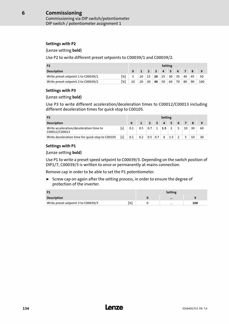
CommissioningCommissioning via DIP switch/potentiometerDIP switch / potentiometer assignment 1
6
� 134 EDS84DG752 EN 7.0
Settings with P2
(Lenze setting bold)
Use P2 to write different preset setpoints to C00039/1 and C00039/2.
P2 Setting
Description 0 1 2 3 4 5 6 7 8 9
Write preset setpoint�1 to C00039/1 [%] 5 10 15 20 25 30 35 40 45 50
Write preset setpoint�2 to C00039/2 [%] 10 20 30 40 50 60 70 80 90 100
Settings with P3
(Lenze setting bold)
Use P3 to write different acceleration/deceleration times to C00012/C00013 includingdifferent deceleration times for quick stop to C00105.
P3 Setting
Description 0 1 2 3 4 5 6 7 8 9
Write acceleration/deceleration time toC00012/C00013
[s] 0.1 0.5 0.7 1 1.5 2 5 10 30 60
Write deceleration time for quick stop to C00105 [s] 0.1 0.2 0.5 0.7 1 1.5 2 5 10 30
Settings with P1
(Lenze setting bold)
Use P1 to write a preset speed setpoint to C00039/3. Depending on the switch position ofDIP1/7, C00039/3 is written to once or permanently at mains connection.
Remove cap in order to be able to set the P1 potentiometer.
ƒ Screw cap on again after the setting process, in order to ensure the degree ofprotection of the inverter.
P1 Setting
Description 0 ... 9
Write preset setpoint�3 to C00039/3 [%] 0 ... 100
CommissioningCommissioning via DIP switch/potentiometer
Before switching on
6
� 135EDS84DG752 EN 7.0
6.3.3 Before switching on
ƒ The wiring unit is mounted and wired as described in the instructions,
– directly on a motor clamping flange or
– with the wall adapter on a suitable surface near the motor.
ƒ Connections with the mains, motor, holding brakes, etc. have been established.
ƒ The communication unit has been mounted and wired according to the scheduledapplication.
– Input and output signals
– Safe input
– Fieldbus
(depending on the version, only optionally available)
ƒ If required, the basic settings for "local mode" have been carried out.
– DIP switch
– Potentiometer
ƒ The drive unit has been mounted and screwed together.
ƒ Use available control functions reasonably, e.g.
– Inhibit controller enable
– Set speed adjustment to the minimum setting
– Activate safety system
ƒ The use of a brake resistor has been checked.
– In the case of dynamic loads or difficult control conditions, the use of the internalE84DZEW47R0001 brake resistor is always recommended for devicesE84DGDVB4024 ... 7524 (4�...�7.5 kW).
� Danger!
Great hazard potential during commissioning
Incorrect settings may cause unexpected and dangerous motor and systemmovements.
Possible consequences:
ƒ Damage to material assets
ƒ Injury to personsProtective measures:
ƒ Clear hazardous area
ƒ Observe safety instructions and safety clearances

CommissioningCommissioning via DIP switch/potentiometerCommissioning steps
6
� 136 EDS84DG752 EN 7.0
6.3.4 Commissioning steps
Proceed step by step:
ƒ Switch on the mains
ƒ Monitor status display
– After a short initialisation time, the display must be blinking green.
ƒ Deactivate requirements of the safety function
ƒ Set controller enable
– After the set starting time, the motor must rotate with the speed set.
ƒ Initial check of the expected behaviour:
– Direction of rotation?
– Starting time?
– Speed?
– Speed control?
ƒ Check of optional control functions:
– Is the analog setpoint selection working?
– Are the digital control signals, e.g. limit switches, working?
– Is the connected motor holding brake working?
– Is the function for changing over the rotating direction working?
– Is the requirement with regard to the safety function working?
– Are the control signals via fieldbus working?
ƒ Switch off drive
– Reduce speed
– Inhibit controller enable
– Switch off mains
� Note!
Save parameter settings safe against mains failure
In order to prevent parameter settings carried out in the device from being lostby mains switching, you have to explicitly save the parameter set with mainsfailure protection in the device.
CommissioningCommissioning via the diagnosis terminal
6
� 137EDS84DG752 EN 7.0
6.4 Commissioning via the diagnosis terminal
The X400 diagnosis terminal serves to quickly and easily set parameters and displaycurrent actual values and device states by means of the corresponding display parameters.For this purpose, the diagnosis terminal must be plugged onto the X70 diagnostic interfaceon the top of the device.
� Danger!
Uncontrolled motor movement possible
In general, changing a parameter causes an immediate response in theinverter.
Possible consequences:
ƒ This may lead to undesirable behaviour on the motor shaft if the inverterhas been enabled.
Protective measures:
ƒ Make changes in small steps and wait for response.
ƒ Certain device commands or settings which may cause critical states of drivebehaviour constitute exceptions. Such parameter changes are only possibleif the inverter is inhibited. Otherwise, a corresponding error message will beissued.
� Note!
Plugging and unplugging the diagnosis terminal during operation ispermissible.
� More information ....
Detailed information regarding the diagnosis terminal can be found in theoperating instructions for the X400 keypad & diagnosis terminal.

CommissioningCommissioning via the diagnosis terminalDisplay elements and function keys
6
� 138 EDS84DG752 EN 7.0
6.4.1 Display elements and function keys
E94AZKAE003
Display Meaning Comment
� LCD display
A1
Headline
<MMM>
Meaning of the menu In the menu level only
<PPP> Meaning of the parameter In the parameter level only
A2
Triple−spaced display
<M1><M2><...>
List of the menus available In the menu level only
<P1><P2><...>
List of the parameters available In the parameter level only
<xxx> Setting of the selected parameter
A3
Status of the basic device
� The basic device is ready for operation.
� The basic device is enabled.
� Application in the basic device is stopped.
� Quick stop active
� The basic device is inhibited. The power outputs are inhibited.
� The basic device is ready to start.
� Speed controller 1 in the limitation The drive is torque−controlled.
Set current limit exceeded in motor or generatormode
! Pulse inhibit active The power outputs are inhibited.
" System error active
# Error active
$ Fault active
% Quick stop by trouble active
& Warning active
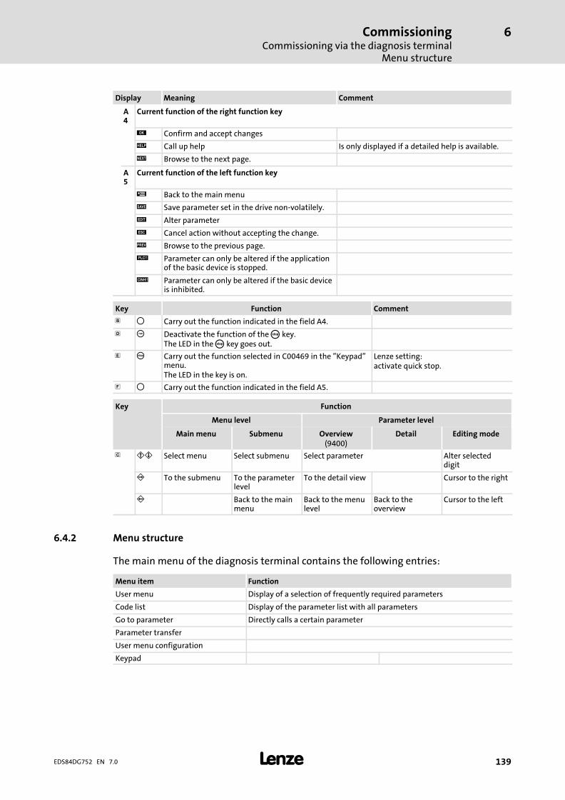
CommissioningCommissioning via the diagnosis terminal
Menu structure
6
� 139EDS84DG752 EN 7.0
CommentMeaningDisplay
A4
Current function of the right function key
' Confirm and accept changes
( Call up help Is only displayed if a detailed help is available.
) Browse to the next page.
A5
Current function of the left function key
* Back to the main menu
+ Save parameter set in the drive non−volatilely.
, Alter parameter
- Cancel action without accepting the change.
. Browse to the previous page.
/ Parameter can only be altered if the applicationof the basic device is stopped.
0 Parameter can only be altered if the basic deviceis inhibited.
Key Function Comment
� 1 Carry out the function indicated in the field A4.
� 2 Deactivate the function of the 3 key.The LED in the 3 key goes out.
� 3 Carry out the function selected in C00469 in the "Keypad"menu.The LED in the key is on.
Lenze setting:activate quick stop.
4 1 Carry out the function indicated in the field A5.
Key Function
Menu level Parameter level
Main menu Submenu Overview(9400)
Detail Editing mode
� 56 Select menu Select submenu Select parameter Alter selecteddigit
7 To the submenu To the parameterlevel
To the detail view Cursor to the right
8 Back to the mainmenu
Back to the menulevel
Back to theoverview
Cursor to the left
6.4.2 Menu structure
The main menu of the diagnosis terminal contains the following entries:
Menu item Function
User menu Display of a selection of frequently required parameters
Code list Display of the parameter list with all parameters
Go to parameter Directly calls a certain parameter
Parameter transfer
User menu configuration
Keypad

CommissioningCommissioning via the diagnosis terminalUser menu
6
� 140 EDS84DG752 EN 7.0
6.4.3 User menu
The user menu can be freely configured in C00517 and contains the following parametersin the Lenze setting:
Parameters
Name Info Lenze setting
C00011 Appl.: Reference speed Setting the reference speed 1500�rpm
C00012 Accel. time − mainsetpoint
FB L_NSet_1: Acceleration time of the rampgenerator for the main speed setpoint
2.0�s
C00013 Decel. time − mainsetpoint
FB L_NSet_1: Deceleration time of the rampgenerator for the main speed setpoint
2.0�s
C00015 VFC: V/f base frequency V/f base frequency for VFCplus motor control 50�Hz
C00016 VFC: Vmin boost Boost of the V/f voltage characteristic within therange of low speed or frequency values for theVFCplus motor control.
2.6�%
C00022 Imax in motor mode Maximum current in motor mode for all motorcontrol modes
5.8�A
C00039/1 Preset setpoint 1(L_NSet_1 n−Fix)
FB L_NSet_1: Fixed speed setpoints (JOG values) forthe setpoint generatorFixed setpoint 1
40.0�%
C00039/2 Fixed setpoint 2 Fixed setpoint 2 60.0�%
C00051 MCTRL: Actual speedvalue
Actual speed value of the motor shaft ˘
C00053 DC−bus voltage Actual DC−bus voltage ˘
C00054 Motor current Current motor current/output current of theinverter
˘
C00061 Heatsink temperature Current heatsink temperature ˘
C00087 Rated motor speed This value can be obtained from the motornameplate. After the motor to be used has beenselected from the motor catalogue, the suitablevalue can be entered automatically.
1320�rpm
C00099 Firmware version Firmware version of the device as string ˘
C00105 Decel. time − quick stop The set deceleration time determines the rampslope at quick stop
5.0�s
C00120 Motor overloadthreshold (I2xt)
Operating threshold for the error message "OC6:Motor overload (I2xt)"
100�%
C00137 Device status Current device state ˘
C00166/3 Mess. − status det. error Textual message of the currently pending error ˘
C00173 Mains voltage Selection of the mains voltage for operating thedevice.
0: "3ph 400V"
C00200 Firmware product type ˘
˘ Read only
CommissioningCommissioning via the diagnosis terminal
Commissioning steps
6
� 141EDS84DG752 EN 7.0
6.4.4 Commissioning steps
� Note!
The following can be connected to the X70 diagnostic interface:ƒ USB diagnostic adapter (E94AZCUS)
ƒ X400 diagnosis terminal (EZAEBK200x)– The functions of the X400 diagnosis terminal and keypad (EZAEBK100x)
are identical.
Only some parameters must be adapted for the drive. Then the drive application can becontrolled immediately in the preset "Terminals 0" control mode via the digital and analoginputs. Alternatively, the keypad can be used for defining the required setpoints andcontrol signals in the "Keypad" control mode.
How to proceed:
1. Wiring of power terminals
– Make use of the mounting instructions supplied with the inverter to wire thepower terminals according to the requirements of your device.
2. Wiring of control terminals.
– The preconfigured I/O connection can be changed via configuration parameters.See the "User−defined terminal assignment" chapter.
– Assignment in the preset "Terminals 0" control mode:

CommissioningCommissioning via the diagnosis terminalCommissioning steps
6
� 142 EDS84DG752 EN 7.0
Terminal Function Info
A1U Setpoint selection 10 V � 1500 rpm (with 4−pole motor)general: 10 V � 100 % reference speed (C00011)
DI1 JOG 1JOG 3
Selection of preset setpoints 1 ... 3� If both inputs are on LOW level, the setpoint selection via the
analog input A1U is active.DI2 JOG 2
DI3 DCB Manual DC−injection braking (DCB)� For HIGH−active inputs, DC−injection braking is active as long as
DI3 is at HIGH level.� After the hold time (C00107) has expired, the inverter sets
pulse inhibit (CINH). DC−injection braking (�Î 110)
DI4 R/L LOW level: CW rotationHIGH level: CCW rotation
DI5 Holding brake Open/close holding brake� Braking modes C02580
3. Check switch at the bottom of the drive unit:
DIP1/1 must be "OFF" (Lenze setting) in order that the parameters can be overwrittenvia »Engineer«, keypad, or fieldbus.
4. If required, carry out communication settings via the DIP switch on theCommunication Unit for fieldbus communication.
The communication settings depend on the fieldbus used.
5. Fasten the controller by means of the 4 screws.
6. Switch on voltage supply of the inverter.
7. Connect keypad.
– Remove the cover of the diagnostic interface on the top of the device and connectthe keypad to the diagnostic interface.
– When the keypad has been connected, the connection to the inverter isestablished. This process is completed when C00051 is shown in the display.
Keypad display Action
MCTRL: Act speed val.C000510 rpm
Use left function key *to change to main menu.
8. Load Lenze setting to inverter.
– For this purpose, the device command "Load Lenze setting" is available which canbe executed via code C00002/1 with the keypad:
� Note!
With the "Load Lenze settings" command, values that have been changedpreviously are overwritten. Default settings for a specific motor, e.g. by Lenzefor a Drive Package, are reset.

CommissioningCommissioning via the diagnosis terminal
Commissioning steps
6
� 143EDS84DG752 EN 7.0
Keypad display Action
Par1 8400 motecUser menu
A Select the menu in the main menu using the 6 navigation key.B Change to the menu using the 7 navigation key.
Load Lenze settingC00002/1
A Use the left function key , to change to the editing mode for C00002/1.B Use navigation key 6 to select the "1: On/Start" entry in the selection list.C Use the right function key ' to accept the executed change and quit the
editing mode.– The load process may take a couple of seconds.
9. Enable inverter: Set RFR to HIGH potential.
– By default, the RFR terminal is bridged (controller enable).
– If the auto−start option "Inhibit at power−on" is activated in C00142 and thecontroller is enabled at mains connection, the controller remains in the"ReadyToSwitchOn" status. For changing to the "SwitchedOn" status, controllerenable must first be deactivated. Only when the controller is enabled againafterwards, the status changes to "OperationEnabled":
– If the autostart option "Inhibit at power−on" is deactivated in C00142, the statusdirectly changes from "ReadyToSwitchOn" to the "SwitchedOn" state and to the"OperationEnabled" state after mains connection when the controller is enabled.
� Danger!
When the auto−start option "Inhibit at power−on" is deactivated, the motorcan directly start after power−on if the controller is enabled!
10. Select speed:
– In the "Terminals 0" by selecting a voltage at the analog input or by selecting afixed setpoint via the digital inputs DI1/DI2.
– In the "Keypad" control mode, the main speed setpoint and the control signals arepredefined via the following parameters:
Parameters Name Info Lenze setting
C00728/3 nMainSetValue_a Main setpoint for the application 100 % � referencespeed (C00011)
0.00�%
C00727/3 bSetSpeedCcw Change of direction of rotation"0": CW rotation"1": CCW rotation
0
C00727/4 bJogSpeed1 Selection of fixed setpoint 1"0": Main setpoint (C00728/3) active."1": Fixed setpoint 1 (C00039/1) active.
0
11. If required, adapt further parameters.
12. Save parameter settings with function key + safe against mains failure in thememory module.

CommissioningCommissioning via the diagnosis terminalSET mode
6
� 144 EDS84DG752 EN 7.0
6.4.5 SET mode
In SET mode, the inverter is controlled via the diagnosis terminal. You can change the speedsetpoint and enable or inhibit the inverter (RFR/run). Other setpoint sources are ignored.
ƒ Activate SET mode: press "DISP" softkey button and confirm with "OK" softkeybutton.
ƒ Exit SET mode: press "DISP" softkey button and confirm with "OK" softkey button.
� Note!
SET mode can only be activated in the "OperationEnabled" device state(controller inhibit is deactivated, green LED on the inverter is lit permanently).
ƒ Controller inhibit is only indicated in the keypad. The cause of controllerinhibit is shown in detail in C00158 (� 8400�motec reference manual).

CommissioningDiagnostics
6
� 145EDS84DG752 EN 7.0
6.5 Diagnostics
On the top side of the Drive Unit, a two−coloured LED display indicates the respectiveoperating status of the inverter. The LED shines through the transparent cap.
green"DRIVE READY"
red"DRIVE ERROR"
Description Device status(Display in C00137)
OFF OFF OFF or initialisation active Init
OFF Safe torque off is active SafeTorqueOff
OFF Device is ready to start ReadyToSwitchON
OFF Device is switched on SwitchedOn
OFF Motor data identification/operation OperationEnabled
The inverter is ready to switch on, switched on, oroperation is enabled and a warning is pending
OFF Trouble active Trouble
OFF Error active Fault
LegendMeaning of the symbols used
LED flashes once approx. every 3 seconds (slow flash)
LED flashes once approx. every 1.25 seconds (flash)
LED flashes twice approx. every 1.25 seconds (double flash)
LED is blinking every second
LED is permanently on

Braking operationBraking operation without additional measures
7
� 146 EDS84DG752 EN 7.0
7 Braking operation
7.1 Braking operation without additional measures
DC injection brake DCB
To decelerate small masses, the "DC injection brake DCB" function can be parameterised.DC−injection braking enables a quick deceleration of the drive to standstill without theneed for an external brake resistor.
ƒ Code C00036 can be used to select the braking current.
ƒ The maximum braking torque to be realised by the DC braking current amounts toapprox. 20 ... 30 % of the rated motor torque. It is lower compared to braking actionin generator mode with external brake resistor.
ƒ Automatic DC−injection braking (Auto−DCB) improves the starting performance ofthe motor when the operation mode without speed feedback is used.
Further information on the relevant parameters can be obtained from the softwaremanual.
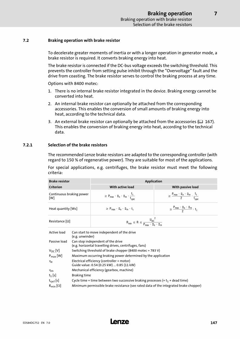
Braking operationBraking operation with brake resistor
Selection of the brake resistors
7
� 147EDS84DG752 EN 7.0
7.2 Braking operation with brake resistor
To decelerate greater moments of inertia or with a longer operation in generator mode, abrake resistor is required. It converts braking energy into heat.
The brake resistor is connected if the DC−bus voltage exceeds the switching threshold. Thisprevents the controller from setting pulse inhibit through the "Overvoltage" fault and thedrive from coasting. The brake resistor serves to control the braking process at any time.
Options with 8400 motec:
1. There is no internal brake resistor integrated in the device. Braking energy cannot beconverted into heat.
2. An internal brake resistor can optionally be attached from the correspondingaccessories. This enables the conversion of small amounts of braking energy intoheat, according to the technical data.
3. An external brake resistor can optionally be attached from the accessories (� 167).This enables the conversion of braking energy into heat, according to the technicaldata.
7.2.1 Selection of the brake resistors
The recommended Lenze brake resistors are adapted to the corresponding controller (withregard to 150 % of regenerative power). They are suitable for most of the applications.
For special applications, e.g. centrifuges, the brake resistor must meet the followingcriteria:
Brake resistor Application
Criterion With active load With passive load
Continuous braking power[W]
� Pmax � �e � �m �t1tzykl
�Pmax � �e � �m
2�
t1tzykl
Heat quantity [Ws] � Pmax � �e � �m � t1 �Pmax � �e � �m
2� t1
Resistance [] Rmin � R �UDC
2
Pmax � �e � �m
Active load Can start to move independent of the drive(e.g. unwinder)
Passive load Can stop independent of the drive(e.g. horizontal travelling drives, centrifuges, fans)
VDC [V] Switching threshold of brake chopper (8400 motec = 783 V)
Pmax [W] Maximum occurring braking power determined by the application
�e Electrical efficiency (controller + motor)Guide value: 0.54 (0.25 kW) ... 0.85 (11 kW)
�m Mechanical efficiency (gearbox, machine)
t1 [s] Braking time
tcycl [s] Cycle time = time between two successive braking processes (= t1 + dead time)
Rmin [�] Minimum permissible brake resistance (see rated data of the integrated brake chopper)
Braking operationBraking operation with brake resistorWiring of brake resistor
7
� 148 EDS84DG752 EN 7.0
7.2.2 Wiring of brake resistor
Danger!
Hazardous electrical voltage
During operation of the standard device and up to 3 minutes after power−offhazardous electrical voltages may occur at the terminals of the brake resistor.
Possible consequences:
ƒ Death or severe injuries when touching the terminals.
Protective measures:
ƒ Disconnect the standard device from the mains before working on the brakeresistor.
ƒ Check all power terminals for isolation from supply.
ƒ Select the mounting location so that the operating conditions mentioned inthe mounting instructions for the brake resistor are permanentlyguaranteed.
� Danger!
Hot surface
The brake resistor may get very hot. (For temperatures see the mountinginstructions for the brake resistor.)
Possible consequences:
ƒ Severe burns when touching the brake resistor.
ƒ Fire or smouldering fire if flammable material is placed near the brakeresistor or may get to it.
Protective measures:
ƒ Before working on the brake resistor, check its surface temperature.
ƒ Select the mounting location so that the operating conditions mentioned inthe mounting instructions for the brake resistor are permanentlyguaranteed.
ƒ Protect the mounting location through fire prevention.
Protect the brake resistor and controller against destruction caused by overload:
ƒ Establish an external safety shutdown using the thermostat of the brake resistor todisconnect the controller from the mains.
ƒ Exception for devices with special connection for the thermostat of the brakeresistor: Use the device−internal safety shutdown.
Connecting cable version
ƒ up to 0.5 m: twisted and unshielded
ƒ from 0.5 to 5 m: shielded
– Use shielded cables to meet the EMC requirements.
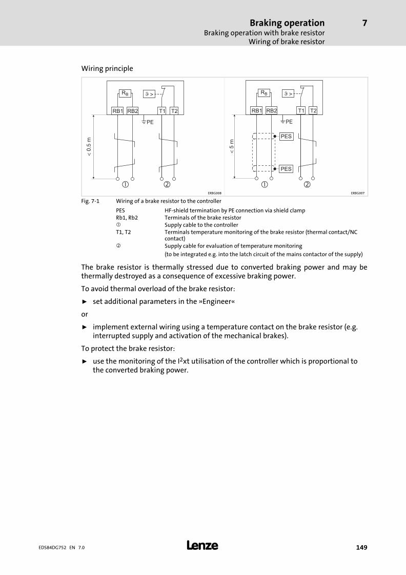
Braking operationBraking operation with brake resistor
Wiring of brake resistor
7
� 149EDS84DG752 EN 7.0
Wiring principle
�
RB
RB1 RB2
<0.
5m
PE
T1 T2
�
RB
RB1 RB2
<5
m
PE
PES
PES
T1 T2
� �ERBG008 ERBG007
Fig. 7−1 Wiring of a brake resistor to the controller
PES HF−shield termination by PE connection via shield clampRb1, Rb2 Terminals of the brake resistor� Supply cable to the controllerT1, T2 Terminals temperature monitoring of the brake resistor (thermal contact/NC
contact)� Supply cable for evaluation of temperature monitoring
(to be integrated e.g. into the latch circuit of the mains contactor of the supply)
The brake resistor is thermally stressed due to converted braking power and may bethermally destroyed as a consequence of excessive braking power.
To avoid thermal overload of the brake resistor:
ƒ set additional parameters in the »Engineer«
or
ƒ implement external wiring using a temperature contact on the brake resistor (e.g.interrupted supply and activation of the mechanical brakes).
To protect the brake resistor:
ƒ use the monitoring of the I2xt utilisation of the controller which is proportional tothe converted braking power.

Braking operationBraking operation with brake resistorWiring of brake resistor
7
� 150 EDS84DG752 EN 7.0
Evaluation of the thermal contact via digital input
The integration of the thermal contact for monitoring the brake resistor can beimplemented via digital input. Use a Lenze system cable. The response to the input signalmust be parameterised using the »Engineer«.
0.37 ... 3 kW 4 ... 7.5 kW
GND-IO
GIO24O
3.3
k
3.3
k
RB2RB1 T1 T2
ERB...E84D...
Rb2Rb1X4 X1DIxDI...
GND-IO
GIO24O
3.3
k
3.3
k
RB2RB1 T1 T2
ERB...E84D...
Rb2Rb1X4 X2DIxDI...
8400DDI032 b 8400DDI032 c
E84D... 8400 motecX4/DIx free digital inputX1/Rb1,Rb2 Connection of the brake resistor for devices 0.37 ... 3 kWX2/Rb1,Rb2 Connection of the brake resistor for devices 4 ... 7.5 kWERB... Brake resistor

Braking operationOperation with spring−applied brake
Introduction
7
� 151EDS84DG752 EN 7.0
7.3 Operation with spring−applied brake
7.3.1 Introduction
Lenze three−phase AC motors and G−motion geared motors can be equipped withspring−applied brakes (motor holding brakes). 8400 motec controllers are provided withan integrated motor brake control.
Switching the brake
The voltage required for controlling the motor brake is generated in the controller,depending on the mains voltage value. The following motor brakes can be connected:
ƒ With 400−V mains: Coil voltage 180 V DC
ƒ With 480−V mains: Coil voltage 215 V DC
Optionally, the switching of the brake can be controlled in addition:
ƒ Via an external control contact (e.g. PLC)
ƒ Via a brake switch which is connected to one of the digital outputs of the controller.The digital output must be parameterised accordingly.
The software manual provides further information on the parameterisation andintegrated brake management.
7.3.2 Wiring
The cable of the motor holding brake can be routed directly by means of a cable gland inparallel to the motor axis.
The motor holding brake is connected to BD1 (+) and BD2 (−).
0.37 ... 3 kW 4 ... 7.5 kW
X1 BD1BD2 L1 L2 L3 Rb1Rb2 U V W T2 T1BD1BD2
+-
X2 BD1BD2 Rb1Rb2U V W T2T1BD1BD2
+ -
E84DG040 BD E84DG078
X1 Terminal in the Wiring Unit for devices 0.37 ... 3 kWX2 Terminal in the Wiring Unit for devices 4 ... 7.5 kWBD1 Connection of spring−applied brake +BD2 Connection of spring−applied brake −9 HF−shield termination by large surface connection to PE.� Earthing (PE)

Safety engineeringIntroduction
8
� 152 EDS84DG752 EN 7.0
8 Safety engineering
8.1 Introduction
With increasing automation, protection of persons against hazardous movements isbecoming more important. Functional safety describes the measures needed by means ofelectrical or electronic equipment to reduce or remove danger caused by failures.
During normal operation, safety equipment prevents people accessing hazardous areas. Incertain operating modes, e.g. set−up mode, work needs to be carried out in hazardousareas. In these situations the machine operator must be protected by integrated drive andcontrol measures.
Drive−based safety provides the conditions in the controls and drives to optimise the safetyfunctions. Planning and installation expenditure is reduced. In comparison to the use ofstandard safety engineering, drive−based safety increases machine functionality andavailability.
Drive−based safety with Inverter Drives 8400
Decentralised drives are frequency inverters that are not mounted locally like controlcabinet devices but are directly attached to the application in the field. Thisproduct−specific feature results in high demands regarding robustness and class ofprotection.
The 8400 motec controllers are optionally available with an integrated safety system.
"Integrated safety" stands for application−oriented safety functions that are applicable onmachines for the protection of persons.
The motion functions continue to be executed by the controller. The integrated safetysystem monitors the safe compliance with the limit values and provides the safe inputsand outputs. If limit values are exceeded, the integrated safety system starts controlfunctions according to EN 60204−1 directly in the controller for the case of an error.
The safety functions are suitable for applications according to IEC 61508 to SIL 3 andachieve the performance level (PL)e according to EN ISO 13849−1. The requirements of thestandard EN 954−1 valid until 30 November 2009 are met until control category 4.
Safety engineeringImportant notes
8
� 153EDS84DG752 EN 7.0
8.2 Important notes
Application as directed
The controllers that are equipped with safety engineering must not be modified by theuser. This concerns the unauthorised exchange or removal of the safety engineering.
� Danger!
Danger to life through improper installation
Improper installation of safety engineering systems can cause an uncontrolledstarting action of the drives.
Possible consequences:
ƒ Death or severe injuries
Protective measures:
ƒ Safety engineering systems may only be installed and commissioned byqualified and skilled personnel.
ƒ All control components (switches, relays, PLC, ...) and the control cabinetmust comply with the requirements of ISO 138491 and ISO 13849−2. Thisincludes i.a.:– Switches, relays with at least IP54 enclosure.– Control cabinet with at least IP54 enclosure.– Please refer to ISO 138491 and ISO 13849−2 for all further requirements.
ƒ Wiring must be shielded.
ƒ All safety relevant cables outside the control cabinet must be protected, e.g.by means of a cable duct:– Ensure that no short circuits can occur.– For further measures see EN ISO 13849−2.
ƒ If an external force acts upon the drive axes, additional brakes are required.Please observe that hanging loads are subject to the force of gravity!
� Danger!
When the "safe torque off" (STO) function is used, an "emergencyswitching−off" according to EN 60204 is not possible without additionalmeasures. There is no electrical isolation, no service switch or repair switchbetween motor and controller!
�Emergency switching−off" requires an electrical isolation, e.g. by a centralmains contactor!
Safety engineeringImportant notesHazard and risk analysis
8
� 154 EDS84DG752 EN 7.0
During operation
After the installation is completed, the operator must check the wiring of the safetyfunction.
The functional test must be repeated at regular intervals. The time intervals to be selecteddepend on the application, the entire system and the corresponding risk analysis. Theinspection interval should not exceed one year.
Residual hazards
In case of a short−circuit of two power transistors a residual movement of the motor of upto 180 °/number of pole pairs may occur! (Example: 4−pole motor residual movementmax. 180 °/2 = 90 °)
This residual movement must be considered in the risk analysis, e.g. safe torque off formain spindle drives.
8.2.1 Hazard and risk analysis
This documentation can only accentuate the need for hazard analysis. The user of theintegrated safety system must read up on standards and the legal situation:
Before the launch of a machine, the manufacturer of the machine must conduct a hazardanalysis according to Machinery Directive 2006/42/EC to determine the hazardsassociated with the application of the machine. The Machinery Directive refers to threebasic principles for the highest possible level of safety:
ƒ Hazard elimination / minimisation by the construction itself.
ƒ Required protective measures must be taken against hazards which cannot beeliminated.
ƒ Existing residual hazards must be documented and the user must be informed ofthem.
Detailed information on the hazard analysis procedure is provided in theDIN EN ISO 12100:2013−08 − ""Safety of machinery − General principles for design, riskassessment and risk reduction". The results of the hazard analysis determine the categoryfor safety−related control systems according to EN ISO 13849−1. Safety−oriented parts ofthe machine control must be compliant.
8.2.2 Standards
Safety regulations are confirmed by laws and other governmental guidelines andmeasures and the prevailing opinion among experts, e.g. by technical regulations.
The regulations and rules to be applied must be observed in accordance with theapplication.
Safety engineeringBasics for safety sensors
8
� 155EDS84DG752 EN 7.0
8.3 Basics for safety sensors
Passive sensors
Passive sensors are two−channel switching elements with contacts. The connecting cablesand the sensor function must be monitored.
The contacts must switch simultaneously (equivalently). Nevertheless, safety functionswill be activated as soon as at least one channel is switched.
The switches must be wired according to the closed−circuit principle.
Examples of passive sensors:
ƒ Door contact switch
ƒ Emergency stop control units
Active sensors
Active sensors are units with 2−channel semiconductor outputs (OSSD outputs). With theintegrated safety system of this device series, test pulses < 1 ms for monitoring theoutputs and cables are permissible. The maximally permissible connection capacity of theoutputs is to be observed. Active sensors are wired directly to the terminals of theintegrated safety system. Monitoring for cross or short circuits must be carried out by theactive sensor.
P/M−switching sensors switch the positive and negative cable or the signal and groundwire of a sensor signal.
The outputs must switch simultaneously (equivalently). Nevertheless, safety functionswill be activated as soon as at least one channel is switched. Active triggering of only onechannel indicates faulty sensors or impermissible wiring.
Examples of active sensors:
ƒ Lightgrid
ƒ Laser scanner
ƒ Control systems

Safety engineeringOperating modeIntroduction
8
� 156 EDS84DG752 EN 7.0
8.4 Operating mode
8.4.1 Introduction
Due to safety option 10, the following safety functions can be used:
ƒ Safe torque off (STO), formerly: safe standstill
If requested, the safe disconnection of the drive is achieved through:
ƒ Directly connected active sensors
ƒ Passive sensors connected to a safety switching device
The safety functions are suitable for applications according to IEC 61508 to SIL 3 andachieve a performance level (PL) e and the control category 4 according to EN ISO 13849−1.
� Danger!
If the request for the safety function is cancelled, the drive will restartautomatically.
You must provide external measures which ensure that the drive only restartsafter a confirmation (EN 60204).
8.4.2 Disconnecting paths
The transmission of the pulse width modulation is safely switched (off) by the safety unit.After this, the power drivers do not generate a rotating field. The motor is safely switchedto torqueless operation (STO).
M
SOSO
PWMPWM
µCµC
PC
3x3x
3x3x
XxxXxx
E84DPSO02
Fig. 8−1 Operating principle of safety unit
SO Safety option 10xxx Control terminals of the safety system or safety busC Control section�C MicrocontrollerPWM Pulse width modulationP Power sectionM Motor
8.4.3 Safety status
When the controller is disconnected from the safety unit, the "Safe torque off" (STO) statusis set (C00155 bit 10 = 1).

Safety engineeringTechnical data
8
� 157EDS84DG752 EN 7.0
8.5 Technical data
Supply
The safe input and the output are isolated and designed for a low−voltage supply througha safely separated power supply unit (SELV/PELV) of 24 V DC. PM−switching input signalsand test pulses � 1 ms are permissible.
Active sensors are directly connected to X61.
Passive sensors are connected to X61 via a switching device. The switching device mustcomply with the required performance level of the application.
There is no monitoring for short circuits.
Detailed features of the inputs and outputs of the safety unit
Classification of binary 24 V interfaces in compliance with ZVEI (German electrical andelectronics manufacturers association): interface type�C, class�1
Terminal Specification [Unit] Min. Typ. Max.
SIA, SIB Low signal V −3.0 0 5.0
High signal V 18 24 30
Input capacitance at switch−off nF 3
Input delay (tolerated test pulse) ms 1.0
Switch−off time (depending on the controller) ms 1.8 2.5 5.0
Running time ms 3.0
Input current SIA mA 35 50
Input current SIB mA 25 50
Input capacitance at switch−on �F 6
Input resistance � 360
Repetition rate of the test pulses ms 10
GI GND potential for SIA / SIB and for the unsafesignalling output
24O Supply voltage through safely separated power supplyunit (SELV/PELV) V 18 24 30
DO Low signal V 0 0.8
High signal V 18 24 30
24O, DO Output current A 0.2
Truth table
Safe input / channel Signallingoutput
Inverter
SIA SIB DO Description of device status Approval
0 0 1"SafeTorqueOff" activated(safe torque off)
0
0 1 0 0
1 0 0 0
1 1 0 Drive active or "ReadyToSwitchOn" 1
Safety engineeringTechnical data
8
� 158 EDS84DG752 EN 7.0
� Note!
Safe inputs are designed with 2 channels (...A/...B). The channels must becontrolled separately and simultaneously (in an equivalent manner).
The active control of only one channel indicates a faulty sensor system or animpermissible interconnection.
Restriction of use
The operation of an integrated safety system is not permissible in earthed phase mains.

Safety engineeringElectrical installation
8
� 159EDS84DG752 EN 7.0
8.6 Electrical installation
X61 − connection of safety system "Safety Option 10"
Pin Connection Description
DOSIB GISIAX61 24O
DC 24 V(+19.2 … +28.8 V)
+
-
�
Terminal strip, 5−pole
E84DG027
SIA Safe input, channel A
SIB Safe input, channel B
GIGND potential for SIA/SIBGND potential for the unsafe signalling output
24O 24 V voltage supply for the unsafe signalling output
DO Unsafe signalling output: "SafeTorqueOff" with a 2−channelrequest by SIA andSIB
X61
E84DG025
X61 a[mm]
[mm2][AWG]
Safety 55
0.5 ... 1.520 ... 16
0.5 ... 1.020 ... 18
0.520
� Note!
The wiring connected for test purposes to the connections of the safety systemmust be removed (e.g. bridges SIA/SIB at 24O).

Safety engineeringCertification
8
� 160 EDS84DG752 EN 7.0
8.7 Certification
� Declarations of conformity and certificates can be found on the internetat:http://www.Lenze.com and on the product CD.

Accessories (overview)Wall mounting
Wall adapter for 0.37�...�3.0�kW
9
� 161EDS84DG752 EN 7.0
9 Accessories (overview)
9.1 Wall mounting
9.1.1 Wall adapter for 0.37�...�3.0�kW
E84DZMAWE1
The wall adapter provides a good remedy, for instance if there is only little space available.The following things are to be taken into consideration:
ƒ A suitable motor cable. Increases the installation effort. (� 161)
ƒ EMC−compliant installation (establishing the CE−typical drive system. (� 75))
E84DZMA010_a
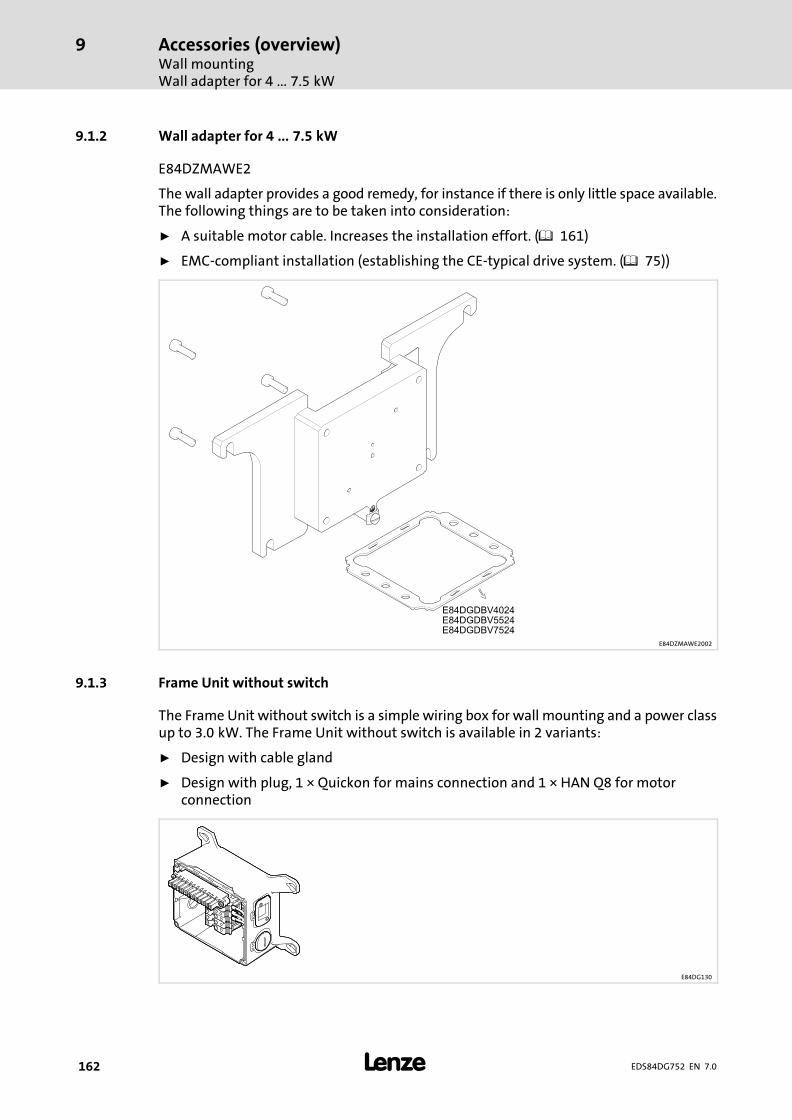
Accessories (overview)Wall mountingWall adapter for 4�...�7.5�kW
9
� 162 EDS84DG752 EN 7.0
9.1.2 Wall adapter for 4�...�7.5�kW
E84DZMAWE2
The wall adapter provides a good remedy, for instance if there is only little space available.The following things are to be taken into consideration:
ƒ A suitable motor cable. Increases the installation effort. (� 161)
ƒ EMC−compliant installation (establishing the CE−typical drive system. (� 75))
E84DZMAWE2002
9.1.3 Frame Unit without switch
The Frame Unit without switch is a simple wiring box for wall mounting and a power classup to 3.0�kW. The Frame Unit without switch is available in 2 variants:
ƒ Design with cable gland
ƒ Design with plug, 1 × Quickon for mains connection and 1 × HAN Q8 for motorconnection
E84DG130

Accessories (overview)Wall mounting
Frame Unit with switch
9
� 163EDS84DG752 EN 7.0
9.1.4 Frame Unit with switch
The Frame Unit with switch is a wiring and switch box for wall mounting and a power classup to 3.0�kW. The Frame Unit with switch is available in the following combinations:
ƒ Design with cable gland
ƒ Design with plug, 2 × HAN Q4/2 for establishing a mains cable loop−throughconnection and 1 × HAN Q8 for implementing the motor connection
ƒ With service switch
ƒ With service switch and control elements
ƒ With service switch and protective function
E84DG129

Accessories (overview)Plug connectorsM12 plug−in connector
9
� 164 EDS84DG752 EN 7.0
9.2 Plug connectors
9.2.1 M12 plug−in connector
The M12 plug−in connector can be easily mounted additionally in the Communication Unitby breaking out the cutouts. The wiring in the Communication Unit is implemented onplug−in terminals, thus making it possible to design additional pluggable I/O´s.
Mode Features M12 plug
M12 plugEZAEVE013/M
� A−coded, 5−pole, female� Packaging unit: 5 items
9.2.2 Plug−in modules
By default, cables for the connection of the mains and the motor are led into the WU bymeans of cable glands. Alternatively, plug−in modules with prewired Q−plugs can besupplied for mounting on the right or the left.
For plug−in modules with a Q−plug, an M16 bore for an additional cable gland is available.
Plug−in modules with two Q−plugs are designed for a looping−through connection(daisy−chain). Like this it is possible to use a supply bus for the machine design.
If wall mounting is implemented, the plug−in modules with a Q8−plug enable the motorconnection as a plug&drive drive, in particular with Lenze system cables.
In the table the retrofittable plug−in modules are listed.
X... Umax Imax IP
[V] [A]
E84DZEVBLANP :X10: Q5
400 ~ 16 ~
~
IP65
E84DZEVBRANP ;
E84DZEVBLAFP : X10: Q5X11: Q5 ~~
E84DZEVBRAFP ; � E84DGDVB3024...
E84DZEVBLPNP :X10: Q4/2
480 ~
24 =
32 ~
10 =
~=E84DZEVBRPNP ;
E84DZEVBLPRP :X10: Q4/2X11: Q4/2 ~=~=
E84DZEVBRPRP ;
E84DZEVBLCNP :X21: Q8 480 ~ 16
E84DZEVBRCNP ;
E84DZEVBLCSP :X10: Quickon 480 ~ 20
~IP65
X21: Q8 480 ~ 16

Accessories (overview)Memory module
9
� 165EDS84DG752 EN 7.0
9.3 Memory module
In the memory module, the parameters of the inverter are stored. The pluggable memorymodule provides for a quick parameter set transfer to an inverter of the same design.Possible reasons for a parameter set transfer:
ƒ Duplication of similar applications in a series of identical drives.
ƒ Restorage of an application after device replacement.
The required steps for a parameter set transfer are described in the software manual.
In order to remove the memory module, use a suitable screwdriver to lever the module outat the upper and lower groove. In order to plug in the module, insert it into the slot and pushit with light pressure until end position is reached.
Mode Features Memory module
Memory moduleE84AYM20S/M
� For 8400 BaseLine, 8400 motec� Packaging unit: 12 items

Accessories (overview)Diagnosis terminal
9
� 166 EDS84DG752 EN 7.0
9.4 Diagnosis terminal
The X400 diagnosis terminal is a simple means for parameter setting and diagnostics onsite. Clearly structured menus and a plain text menu provide for quick data access. Thediagnosis terminal is connected to the X70 diagnostic interface. The diagnosis terminal isbased on the X400 keypad, extended by a holder and a connecting cable.
Mode Features Diagnosis terminal
DiagnosisterminalEZAEBK2003
� 2.5�m connecting cable, exchangeable� Menu−driven diagnostics and parameter
setting� Backlighted graphic display for representing
information� 4 navigation keys, 2 context−sensitive keys� Adjustable RUN/STOP function� Supports hot plugging� Enclosure IP20

Accessories (overview)Switch/potentiometer unit
9
� 167EDS84DG752 EN 7.0
9.5 Switch/potentiometer unit
By means of the switch/potentiometer unit and the 8400�motec inverter integrated in theinverter, an analog setpoint can be predefined using the integrated potentiometer. Via therotary switch, the drive can for example be started or stopped, or the direction of rotationcan be changed.
Mode Features Switch/potentiometer unit
Switch/potentiometer unitE82ZBU
� 2.5�m connecting cable� IP65 enclosure

Accessories (overview)External brake resistors − mounting variant
9
� 168 EDS84DG752 EN 7.0
9.6 External brake resistors − mounting variant
E84DZEWxxxx001
E84DZEV012a
RB(C00129)
PD(C00130)
QB(C00131)
C00574 IP E84DGDVB...
� �
[�] [W] [W] [kWs] =
E84DZEW220R001 220 40 30 0.6 1 Fault IP65 37145514751411241524
E84DZEW100R001 100 40 30 0.6 1 Fault IP65 22243024
E84DZEW47R0001 47 40 30 0.6 1 Fault IP65 402455247524

Accessories (overview)External brake resistors
9
� 169EDS84DG752 EN 7.0
9.7 External brake resistors
Braking greater moments of inertia or longer operation in generator mode requires the useof an external brake resistor.
The brake resistors recommended in the table below are dimensioned to approx. 1.5 timesthe regenerative power at a cycle time of 15/135�s (brake/pause ratio). As a general rule,these brake resistors meet the common requirements with regard to standardapplications.
The brake resistors are provided with a thermostat (potential−free NC contact).
ERBSECS000
Typicalmotor
power 1)
Mainsvoltage
Brakeresistor
Ratedresistance
Ratedpower
Heatcapacity
Dimensions Mass
P[kW]
UAC[V]
Rrated[�]
Prated[W]
Cth[kWs]
h × b × t[mm]
m[kg]
0.37
3 AC320�...�528
ERBS180R350W 180.0 350.0 53.0 382 × 124 × 122 2.0
0.55
0.75
1.10
1.50
2.20ERBS100R625W 100.0 625.0 94.0 566 × 124 × 122 3.0
3.00
4.00ERBS047R400WERBS047R800W
47.047.0
400.0800.0
60.0120.0
400 × 110 × 105710 × 110 × 105
2.33.9
5.50
7.501) Typical motor power of a 4−pole asynchronous motor
AppendixTotal index
10
�170 EDS84DG752 EN 7.0
10 Appendix
10.1 Total index
Zahlen8400 motec Set, motec Set, 26
AAccessories, 161
− Brake resistor, 147
Ambient conditions
− climatic, 32
− mechanical, 32
BBrake resistor, 54, 57, 60
− Selection, 147
− Wiring, 148
Braking, 146
Braking operation, 146
− DC injection brake DCB, 146
− with brake resistor, 147
− without additional measures, 146
CCable
− For control connections, 77
− for the motor connection, 76
Cables
− cross−sections, 38, 40, 42, 44
− fuses, 38, 40, 42, 44
CANopen, 64, 101
− STO, 103
Commissioning, 121
− before you start, 121
Communication Unit, 25
Control cable, 77
Control terminals, 61, 94
DDefinition of notes used, 11
Definitions, Terms, 10
Device features, 20
Device protection, 18, 71
Diagnosis terminal, 166
Disconnecting paths, 156
Disposal, 14
Drive Unit, 25
− settings, 85
EElectrical installation, 159
EMC, what to do in case of interferences, 77
EN 61000−3−2, 33
Enclosure, 30
FField Package
− with switch, 47, 90
− without switch, 45, 90
Frame Unit, 24
− with switch, 47, 90
− without switch, 45, 90
Fuses, 38, 40, 42, 44
− operation with rated power, 400 V (UL), 38, 42
GGeneral data, 62
HHarmonic currents, limitation according to EN 61000−3−2,33
Hazard analysis, 154
IIdentification, 22
Installation, 70
− electrical, 159
Interferences, eliminating EMC interferences, 77
Introduction, 156
IT system, 86
− measures, 86
MMains current, 37, 39, 41, 43
Memory module, 123, 165
AppendixTotal index
10
� 171EDS84DG752 EN 7.0
Menu structure, 139
Motor cable, 76
− length, 31
Motor power, typical, 37, 39, 41, 43
Motor protection, 18
Mounting place, 32
Mounting position, 32
NNameplate, 22
Noise emission, 33
Noise immunity, 33
Notes, definition, 11
OOperating conditions, ambient conditions
− climatic, 32
− mechanical, 32
Operation, Overcurrent, 49
Output power, 37, 39, 41, 43
Output voltage, maximum, 35
Output voltage , 35
Overspeeds, 18
Overview
− Accessories, 161
− control terminals, 29
PPollution, 32
Power system, 31
Power terminals, 52, 91
Product description, 19
Protection of persons, 18
Protective insulation of control circuits, 31
Protective measures, 31
RRated data
− Operation with increased power, 400 V mains, 39
− operation with increased power , 480 V system, 43
Residual hazards, 18, 154
Risk analysis, 154
SSafety, safety engineering, 152
Safety engineering, 152
− application as directed, 153
− Certification, 160
Safety functions, safety instructions, during operation,154
Safety instructions, 12
− definition, 11
− during operation, 154
− layout, 11
Safety status, 156
Sensors, basics, 155
Site altitude, 32
Supply conditions, 31
− mains, 31
− motor, 31
Switching frequency reduction, 51
System overview, 61
TTechnical data, 30, 157
− General data, 62
− Operation with increased power, 400 V mains, 39
− operation with increased power , 480 V system, 43
Terms, definitions, 10
Total index, 170
Type code, finding, 22
UUse in IT systems, 86
User menu, 140
VValidity, documentation, 7
WWiring, Brake resistor, 148
Wiring Unit, 23

© 02/2018
� Lenze Drives GmbHPostfach 10 13 52, 31763 HamelnBreslauer Straße 3, 32699 ExtertalGERMANYHR Lemgo B 6478
Service Lenze Service GmbHBreslauer Straße 3, D−32699 Extertal
Germany
� +49�5154�82−0 � 008000 2446877 (24 h helpline)
� +49�5154�82−2800 � +49�5154�82−1112
� [email protected] � [email protected]
� www.lenze.com
EDS84DG752 .W÷Q EN 7.0 TD2910 9 8 7 6 5 4 3 2 1


