54
Hardware Manual Indel motion boards Made in Switzerland Rev 1.31 © Indel AG, 04/11/2013 Language: English
Hardware Manual
Indel motion boards
Made in Switzerland
Rev 1.31 © Indel AG, 04/11/2013
Language: English

Table of contents Indel motion boards
Tabel of contents1 Description ...................................... ..............................................................................4
1.1 Position controller............................. .............................................................................................4
1.2 Assembly groups................................. ...........................................................................................5
2 Safety notes ..................................... ..............................................................................6
2.1 General safety notes............................ ..........................................................................................6
2.2 Safety requirements............................. ..........................................................................................72.2.1 Risk analysis.....................................................................................................................................72.2.2 24V DC power supply.......................................................................................................................8
2.2.3 48V DC power supply (motor supply)..............................................................................................82.2.4 EMV..................................................................................................................................................8
2.2.5 Commissioning.................................................................................................................................8
2.2.6 Intended use.....................................................................................................................................82.2.7 Plug-in connections..........................................................................................................................9
2.2.8 Responsibility...................................................................................................................................9
3 Technical details ................................ ..........................................................................10
3.1 Technical details for motion boards............. ..............................................................................10
3.2 Technical details for connector boards.......... ............................................................................173.2.1 MAX-DBIT......................................................................................................................................173.2.2 MAX-DBMT....................................................................................................................................18
3.3 Dimensions, pin assignment...................... .................................................................................193.3.1 Dimensions of AX4.........................................................................................................................193.3.2 Pin arrangement for AX4 board......................................................................................................20
3.3.3 Pin assignment for digital inputs and outputs in AX4.....................................................................21
3.3.4 Pin assignment for supplies and interfaces in AX4........................................................................223.3.5 Pin assignment for AX4 encoder systems.....................................................................................23
3.3.6 Pin assignment for motors in AX4..................................................................................................263.3.7 Dimensions of MAX boards............................................................................................................28
3.3.8 Pin assignment for MAX-2,4...........................................................................................................35
3.3.9 Pin assignment for MAX-2..............................................................................................................363.3.10 Pin assignment for MAX-4..............................................................................................................37
3.3.11 Supplies to MAX boards.................................................................................................................38
4 Serial interface ................................. ...........................................................................39
5 Connection examples............................... ...................................................................40
5.1 Motors on MAX2 board............................ ....................................................................................40
5.2 Wiring of digital inputs and outputs............ ...............................................................................42
6 Installation...................................... ..............................................................................43
6.1 Cooling and ventilation......................... .......................................................................................446.1.1 Notes on UL directive.....................................................................................................................456.1.2 Braking resistance..........................................................................................................................45
7 Operation ........................................ .............................................................................46
Page 2/54 Rev 1.31 © 04/11/2013

Table of contents Indel motion boards
7.1 Braking resistor................................ ............................................................................................46
7.2 Motion boards with an ethernet interface........ ..........................................................................46
8 Fieldbus systems.................................. .......................................................................47
8.1 GinLink ........................................ ..................................................................................................47
8.2 INFO-Link....................................... ................................................................................................48
8.3 Error messages ................................. ...........................................................................................49
8.4 Warnings........................................ ................................................................................................49
9 Sales and service................................. ........................................................................50
9.1 Manufacturer ................................... .............................................................................................50
9.2 Maintenance, cleaning, repair................... ..................................................................................50
9.3 Transport and storage........................... .......................................................................................50
9.4 Disposal........................................ .................................................................................................50
9.5 Declaration of conformity....................... .....................................................................................51
10 List of figures.................................. .............................................................................53
11 Document status.................................. ........................................................................54
Page 3/54 Rev 1.31 © 04/11/2013
Description Indel motion boards
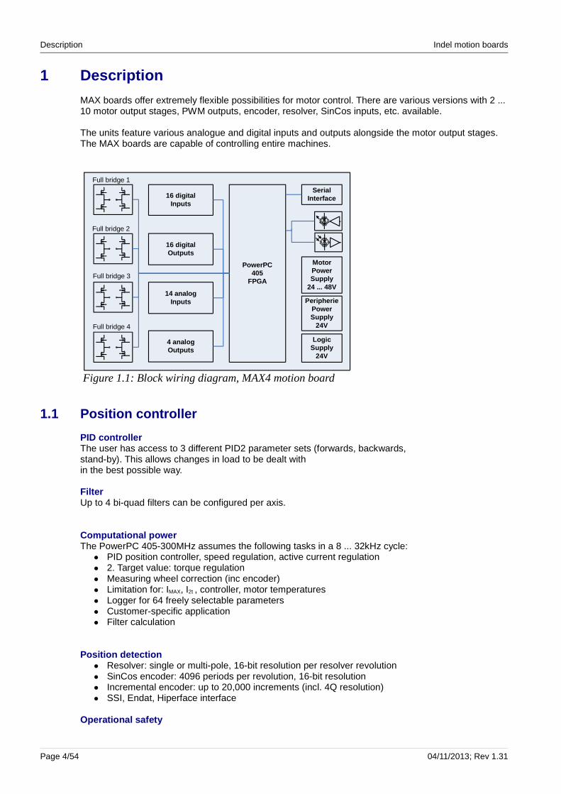
1 Description
MAX boards offer extremely flexible possibilities for motor control. There are various versions with 2 ... 10 motor output stages, PWM outputs, encoder, resolver, SinCos inputs, etc. available.
The units feature various analogue and digital inputs and outputs alongside the motor output stages. The MAX boards are capable of controlling entire machines.
1.1 Position controller
PID controllerThe user has access to 3 different PID2 parameter sets (forwards, backwards,stand-by). This allows changes in load to be dealt within the best possible way.
FilterUp to 4 bi-quad filters can be configured per axis.
Computational powerThe PowerPC 405-300MHz assumes the following tasks in a 8 ... 32kHz cycle:● PID position controller, speed regulation, active current regulation● 2. Target value: torque regulation● Measuring wheel correction (inc encoder)● Limitation for: IMAX, I2t , controller, motor temperatures● Logger for 64 freely selectable parameters● Customer-specific application● Filter calculation
Position detection● Resolver: single or multi-pole, 16-bit resolution per resolver revolution● SinCos encoder: 4096 periods per revolution, 16-bit resolution● Incremental encoder: up to 20,000 increments (incl. 4Q resolution)● SSI, Endat, Hiperface interface
Operational safety
Page 4/54 04/11/2013; Rev 1.31
Figure 1.1: Block wiring diagram, MAX4 motion board
Full bridge 2
Full bridge 4
Full bridge 3
Full bridge 1
16 digital Inputs
16 digital Outputs
14 analogInputs
4 analogOutputs
PowerPC405
FPGA
Motor Power Supply
24 ... 48V
PeripheriePowerSupply
24V
LogicSupply
24V
Serial Interface

Indel motion boards Description
A number of variables are continually monitored within the motion boards: short-circuit monitors switch off the controller in the case of motor or ground short-circuit.
Rapid overcurrent cut-outs protect the motor and output stage within the individual phases. These intervene when the drive is stuck or is stopped suddenly.
The motor and output stage are monitored for overheating.
1.2 Assembly groups
Order no. Type Description
611041900 GIN-AX4 4/2 Axis Board with C96-PPC-Card4, 16 Input, 16 Output
610838600 GIN-MAX10 Multiaxis DC-Motor Module, 6x2.5A, 4x1.25A, 16 Out 24V 2A, 16 Inp 24V, 4 Analogue Input
610636340-4x2.5A GIN-MAX4 Multi-Axes Board, 4 x 3-Phase 48V/2.5A, 16x24V/2A IO, 14 x Analog Input +-10V, 4 x Analog Out +-10V
610636341-2x5A GIN-MAX4 Multi-Axis Board, 2 x 3-Phase 48V/5A, 16x24V/2A IO, 14 x Analog Input +-10V, 4 x Analog Out +-10V
610636300-4x2.5A INFO-MAX4 Multi-Axes Board, 4 x 3-Phase 48V/2.5A, 16x24V/2A IO,14 x Analog Input +-10V, 4 x Analog Out +-10V
610636301-2x5A INFO-MAX4 Multi-Axis Board, 2 x 3-Phase 48V/5A, 16x24V/2A IO, 14 x Analog Input +-10V, 4 x Analog Out +-10V
610535700 MAX2-DBIT Distribution Board for MAX-2
610636400 MAX4-DBIT Distribution Board for MAX-4
610636501 MAX-DBMT Distribution Board for MAX Boards with 2 Resolvers Inputs and 2 PWM 48V/3A outputs resistant to short-circuiting
Rev 1.31; 04/11/2013 Page 5/54

Safety notes Indel motion boards
2 Safety notes
QuestionsThese safety notes do not claim to be exhaustive. Please call us if you have any questions or problems. (Tel. +41 44 956 20 00)
2.1 General safety notes
DocumentationPlease read this documentation fully before installation and commissioning. Incorrect handling of the modules can lead to personal injury or property damage. Ensure that the technical details and information on connection conditions are complied with.
Qualified personnelOnly qualified specialist personnel may carry out work such as transport, assembly, installation, commissioning, servicing and maintenance.
National accident prevention regulations must be observed.
ESD protectionThe modules contain components that are sensitive to static charge, and that can be damaged through improper handling. Discharge the static from your body before touching the modules. Avoid contact with highly insulating materials (artificial fibres, plastic film, etc.). Place the modules on a conductive surface in a voltage-free state.
Do not touch the plug connector contacts on the drive and the connected cables, or contact pins on conductors.
Page 6/54 04/11/2013; Rev 1.31

Indel motion boards Safety notes
2.2 Safety requirements
2.2.1 Risk analysisThe machine manufacturer must compile a risk analysis for the machine and take suitable measures to ensure that unforeseen movements do not cause damage to persons or property.
Notes on possible risks are also provided in other places throughout this document. All notes on risks, warnings, precautions and information must be observed.
Run-onIf application-dependent risks arise due to run-on, additional protective measures (e.g. moveable covers with locking) must be taken to cover the danger zone until such a time that the risk to persons or property no longer exists.
It must be noted that run-on of the drive is possible without a mechanical brake or defective brake. The securing brake is not safely controlled by the Indel servo drives. (Active output)
Braking resistanceThe braking resistor is not safely controlled by the Indel servo drives. A defective or incorrectly connected braking resistor will result in the motor not stopping within the expected time span. In unfortunate cases, this can lead to personal injury or property damage.
Protection from dangerous movementsIncorrect control of motors can trigger unwanted and dangerous movements.
Such behaviour may be caused by, for example:● Faulty installation● Faulty configuration● Faulty or incomplete wiring● Defective devices or cables● Faulty control by the software
Essentially, movement of the motor should be expected as soon as the motion board is switched on. Protection of persons and the machine can only be guaranteed by means of overarching safety measures.
Suitable measures must be taken to ensure that the movement zone of machines are protected against unintentional access by persons.
Removing, bypassing or circumventing the safety mechanisms is strictly prohibited.
Plenty of easily accessible emergency stop switches must be available in and around the machine.
Suspended loadsIn the case of suspended loads, additional measures must be taken to ensure that the axis stays in place. The Indel servo drives do not offer outputs that allow you to safely control securing brakes. Holding brakes do not offer any protection when slowing down the motor.
Rev 1.31; 04/11/2013 Page 7/54

Safety notes Indel motion boards
Further notesThe emergency stop function may not necessarily lead to the energy supply being switched off. Drives may remain in operation. Protection against touching live parts is therefore not necessarily guaranteed.
Position switches and actuating controls must be secured against shifting in accordance with EN1088.
The reaction in the event of a power cut must be considered.
2.2.2 24V DC power supplyThe motor may spin out in the event of loss of the 24V power supply to the motion board. If this is not permissible, external measures must be taken to prevent the axis from spinning out.
2.2.3 48V DC power supply (motor supply)The motor may spin out in the event of loss of the 48V DC power supply to the motors. If the intermediate circuit voltage UCC falls below the configured limit UCC MIN, the motor control will go into error mode and the motor will be switched off.
2.2.4 EMVFor EMC-compliant wiring, see the Indel wiring guidelines, as well as the wiring instructions in this document.
The manufacturer of machines or systems must take additional EMC safety measuresif the product standard applicable to their machine stipulates lower limit values. Additional EMC safety measures may be required for machines that contain a large number of Indel servo drives. In such cases, the installation of a central mains filter is usually sufficient.
When using Indel motion boards in residential areas or when connecting Indel motion boards to a low-voltage network that will supply buildings in residential areas without intermediate transformers, additional measures must be implemented in order to filter out interference.
2.2.5 CommissioningBefore switching on a motion board, it must be ensured that the unit is correctly connected to the earth potential. The earth connections must always be put in place, even if the motion board is only being operated for testing purposes.
The commissioning must be documented and proof of the safety functions must be kept.
2.2.6 Intended useThe Indel motion boards must only be used within the framework specified in this document and other documents to which it refers.
Intended use is prohibited until it has been established that the machine complies with the provisions of EC Directive 2006/42/EC (Machinery Directive) and Directive 2004/108/EEC (EMC Directive), or the relevant current version of said directives. Otherwise, the Indel motion board cannot be marketed.
Additional measures must be taken for use in areas at risk of explosion, such as flame-proof enclosure in accordance with EN 50014 and EN 50018.
Page 8/54 04/11/2013; Rev 1.31
Indel motion boards Safety notes
2.2.7 Plug-in connectionsPlug-in connections must never be plugged in or unplugged when the unit is switched on.
2.2.8 ResponsibilityThe motion boards are not completely safe from failure, particularly the safety functions. In the event of failure, the operator is responsible for ensuring that the machine/system is put into a safe condition.
Rev 1.31; 04/11/2013 Page 9/54
All diagnosis and monitoring functions can only int errupt the control of the motor. This means that the motor becomes currentless and can no longer be controlled or slowed down!
Depending on the application, additional measures a re required to slow down or stop the motor.
The operator is responsible for safety.
Technical details Indel motion boards
3 Technical details
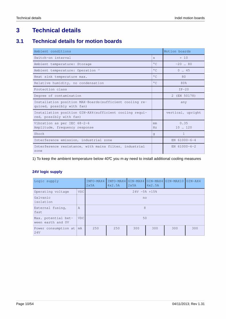
3.1 Technical details for motion boards
Ambient conditions Motion boards
Switch-on interval s > 10
Ambient temperature: Storage °C -20 … 80
Ambient temperature: Operation 1) °C 0 … 45
Heat sink temperature max. °C 80
Relative humidity, no condensation °C 80%
Protection class IP-20
Degree of contamination 2 (EN 50178)
Installation position MAX-Boards(sufficient cooling re-quired, possibly with fan)
any
Installation position GIN-AX4(sufficient cooling re qui-red, possibly with fan)
vertical, upright
Vibration as per IEC 68-2-6 Amplitude, frequency response
mmHz
0.3510 … 120
Shock g 1
Interference emission, industrial zone EN 61000-6-4
Interference resistance, with mains filter, industr ial zone
EN 61000-6-2
1) To keep the ambient temperature below 40°C you m ay need to install additional cooling measures
24V logic supply
Logic supply INFO-MAX42x5A
INFO-MAX44x2.5A
GIN-MAX42x5A
GIN-MAX44x2.5A
GIN-MAX10 GIN-AX4
Operating voltage VDC 24V -5% +15%
Galvanic isolation
no
External fusing, fast
A 8
Max. potential bet-ween earth and 0V
VDC 50
Power consumption at 24V
mA 250 250 300 300 300 300
Page 10/54 04/11/2013; Rev 1.31

Indel motion boards Technical details
On-board supplies
Supplies MAX-2,4,10 AX4
Voltage V ± 15 / ± 15%
Power (± 15V supply) mA 50
Voltage V ± 5 / ± 5%
Power (± 5V supply) mA 100
Supply for encoders; voltage V 5 / ± 5% 5 / ± 5%
Power (5V supply) mA 600 600
Supply for logic; voltage V 3.3 / ± 5%
Power (3.3V supply) mA 50
Motors
Motor Motion boards
Minimum inductance mH 1
Minimum resistance Ohm 0.2
Max. Cable lengthin the case of cable lengths > 20m use choke 0.5 … 1mH
m 20
Min. Cable length in parallel operation of GIN-AX4Minimum length of the parallel strands of the motor connections.
m 0.12
Motor temperature monitoringBi-metal sensor must be in motor cableMotor temperature monitoring only for AX4
Bi-metalKTX-84 100 / 110
PTC10k GT2
Accuracy of analogue temperature sensors °C ± 2
Motor cable shielded
Motor types:- Synchronous servo motors and brushless asynchrono us motors- DC motors, linear motors, stepper motors (two coi ls)The motors must be designed for operation using dig ital servo drives
Rev 1.31; 04/11/2013 Page 11/54

Technical details Indel motion boards
MAX boards output stages
Nominal values MAX44x2.5A
MAX42x5A
MAX10 AX44x5A
AX42x10A
Number of output stages(MAX-10 only DC motors)
4 2 10 4 2
Motor supply voltage VDC 15 … 48 0 … 48
Overvoltage cut-off VDC 54
Overheating cut-off °C 80
Max. Output per motor W 100 200 4 x 506 x 100
200 400
I rated at 8kHz sampling rate
Arms 2.5 5.0 1.25 / 2.5 5.0 10.0
I MAX at 8kHz sampling rate Arms 2.5 5.0 1.25 / 2.5 5.0 10.0
I rated at 12kHz sampling rate
Arms 2.5 5.0 1.25 / 2.5 5.0 10.0
I MAX at 12kHz sampling rate
Arms 2.5 5.0 1.25 / 2.5 5.0 10.0
I rated at 16kHz sampling rate
Arms 5.0 5.0 10.0
I MAX at 16kHz sampling rate
Arms 5.0 5.0 10.0
I MAX brake FET ADC 5 5 - 10 10
Minimum external braking resistance(48V supply)
Ohm 10 10 10 10
External fusing, triggering characteri-stic: Slow, C
A 10 10 10 20 20
Power dissipation W 25 25 25 35 25
Weight Kg
PWM oversampling for motor drive: Sampling rate x2, x3, x4Iron-less motors run better with PWM oversampling.
Feedback systems
MAX-2/4total of 4 encoder inputs: 2 incremental encoder inputs, as well as 2 inputs that can be configured as either an incremental encoder input or a SinCos input.
MAX-1010 x incremental encoder inputs
AX4 (SinCos)4 encoder inputs: each encoder input can be configured as an incremental encoder or SinCos encoder.Plus 2 digital interfaces for Hiperface, Endat, SSI (motor 1, 3)
Page 12/54 04/11/2013; Rev 1.31
Indel motion boards Technical details
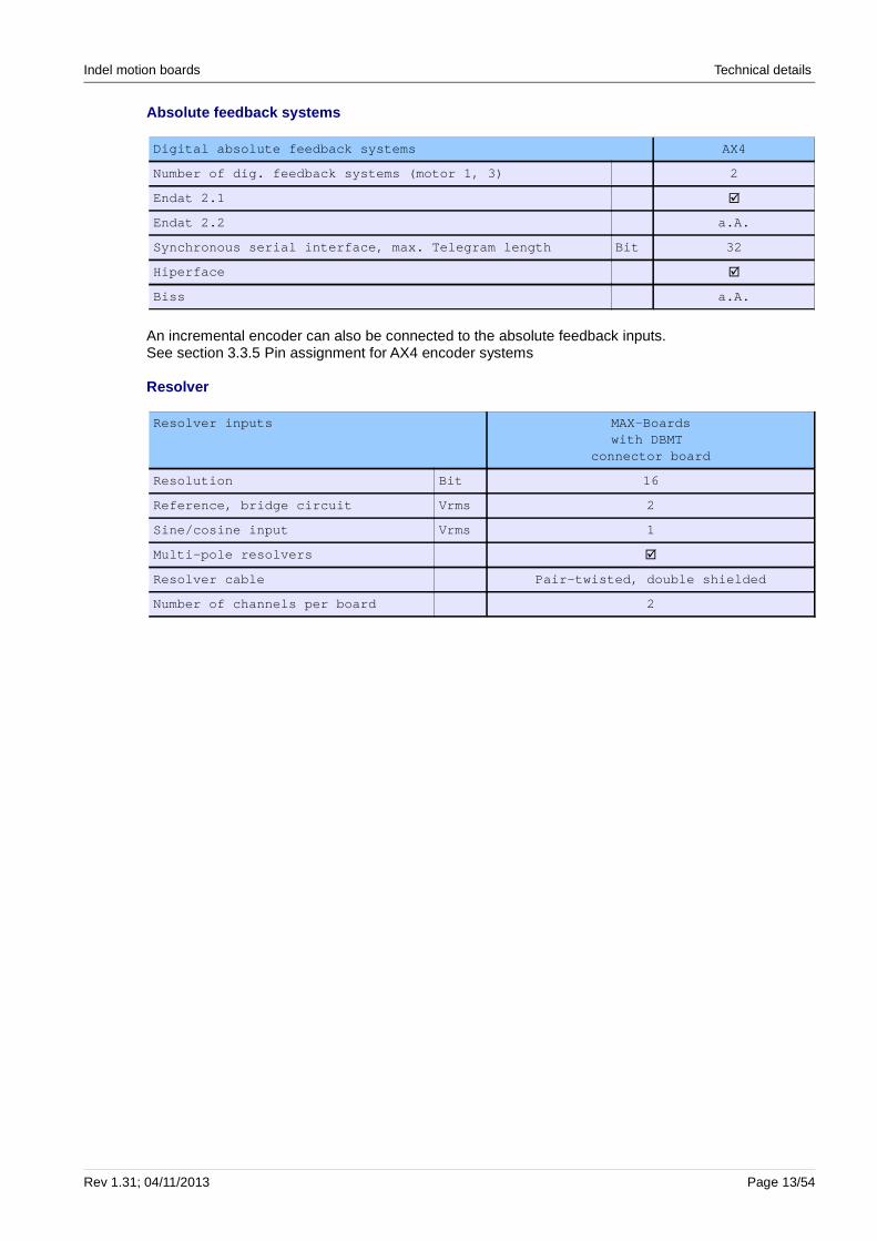
Absolute feedback systems
Digital absolute feedback systems AX4
Number of dig. feedback systems (motor 1, 3) 2
Endat 2.1 �
Endat 2.2 a.A.
Synchronous serial interface, max. Telegram length B it 32
Hiperface �
Biss a.A.
An incremental encoder can also be connected to the absolute feedback inputs.See section 3.3.5 Pin assignment for AX4 encoder systems
Resolver
Resolver inputs MAX-Boardswith DBMT
connector board
Resolution Bit 16
Reference, bridge circuit Vrms 2
Sine/cosine input Vrms 1
Multi-pole resolvers �
Resolver cable Pair-twisted, double shielded
Number of channels per board 2
Rev 1.31; 04/11/2013 Page 13/54
Technical details Indel motion boards
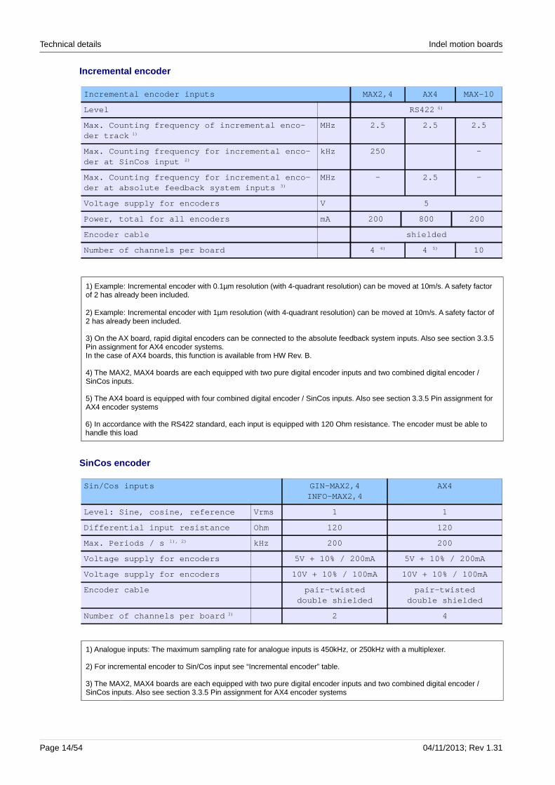
Incremental encoder
Incremental encoder inputs MAX2,4 AX4 MAX-10
Level RS422 6)
Max. Counting frequency of incremental enco-der track 1)
MHz 2.5 2.5 2.5
Max. Counting frequency for incremental enco-der at SinCos input 2)
kHz 250 -
Max. Counting frequency for incremental enco-der at absolute feedback system inputs 3)
MHz - 2.5 -
Voltage supply for encoders V 5
Power, total for all encoders mA 200 800 200
Encoder cable shielded
Number of channels per board 4 4) 4 5) 10
SinCos encoder
Sin/Cos inputs GIN-MAX2,4INFO-MAX2,4
AX4
Level: Sine, cosine, reference Vrms 1 1
Differential input resistance Ohm 120 120
Max. Periods / s 1), 2) kHz 200 200
Voltage supply for encoders 5V + 10% / 200mA 5V + 10% / 200mA
Voltage supply for encoders 10V + 10% / 100mA 10V + 1 0% / 100mA
Encoder cable pair-twisteddouble shielded
pair-twisteddouble shielded
Number of channels per board 3) 2 4
Page 14/54 04/11/2013; Rev 1.31
1) Example: Incremental encoder with 0.1µm resolution (with 4-quadrant resolution) can be moved at 10m/s. A safety factor of 2 has already been included.
2) Example: Incremental encoder with 1µm resolution (with 4-quadrant resolution) can be moved at 10m/s. A safety factor of 2 has already been included.
3) On the AX board, rapid digital encoders can be connected to the absolute feedback system inputs. Also see section 3.3.5 Pin assignment for AX4 encoder systems.In the case of AX4 boards, this function is available from HW Rev. B.
4) The MAX2, MAX4 boards are each equipped with two pure digital encoder inputs and two combined digital encoder / SinCos inputs.
5) The AX4 board is equipped with four combined digital encoder / SinCos inputs. Also see section 3.3.5 Pin assignment for AX4 encoder systems
6) In accordance with the RS422 standard, each input is equipped with 120 Ohm resistance. The encoder must be able to handle this load
1) Analogue inputs: The maximum sampling rate for analogue inputs is 450kHz, or 250kHz with a multiplexer.
2) For incremental encoder to Sin/Cos input see “Incremental encoder” table.
3) The MAX2, MAX4 boards are each equipped with two pure digital encoder inputs and two combined digital encoder / SinCos inputs. Also see section 3.3.5 Pin assignment for AX4 encoder systems
Indel motion boards Technical details
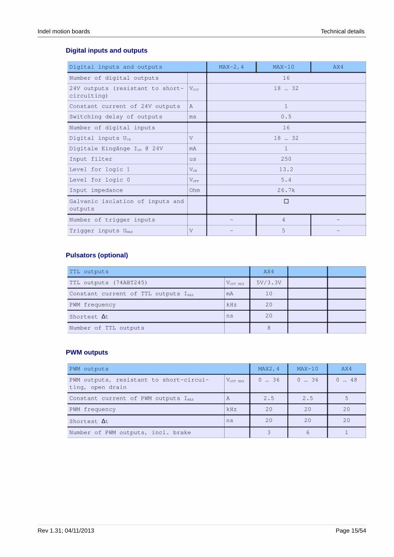
Digital inputs and outputs
Digital inputs and outputs MAX-2,4 MAX-10 AX4
Number of digital outputs 16
24V outputs (resistant to short-circuiting)
VOUT 18 … 32
Constant current of 24V outputs A 1
Switching delay of outputs ms 0.5
Number of digital inputs 16
Digital inputs U IN V 18 … 32
Digitale Eingänge I ON @ 24V mA 1
Input filter us 250
Level for logic 1 V ON 13.2
Level for logic 0 V OFF 5.4
Input impedance Ohm 26.7k
Galvanic isolation of inputs and outputs
�
Number of trigger inputs - 4 -
Trigger inputs U MAX V - 5 -
Pulsators (optional)
TTL outputs AX4
TTL outputs (74ABT245) V OUT MAX 5V/3.3V
Constant current of TTL outputs I MAX mA 10
PWM frequency kHz 20
Shortest ∆t ns 20
Number of TTL outputs 8
PWM outputs
PWM outputs MAX2,4 MAX-10 AX4
PWM outputs, resistant to short-circui-ting, open drain
VOUT MAX 0 … 36 0 … 36 0 … 48
Constant current of PWM outputs I MAX A 2.5 2.5 5
PWM frequency kHz 20 20 20
Shortest ∆t ns 20 20 20
Number of PWM outputs, incl. brake 3 6 1
Rev 1.31; 04/11/2013 Page 15/54

Technical details Indel motion boards
Analogue inputs and outputs
Analogue inputs and outputs MAX2,4 MAX-10 AX4
Number of analogue inputs 14 4 -
Ranges V ± 10± 1
± 0.1
± 5
Converter time / channel Khz 4 8 … 12
Resolution Bit 16 16
Average filter 1 … 256 1 … 256
Number of analogue outputs 4 - -
Range V ± 10
Power per channel I MAX mA 5
Resolution Bit 16
Accuracy 1 ‰
Once switched on, the output of the analogue outputs is -12V over 300ms.
Accuracy of analogue inputs
Accuracy of ana-logue inputsMeasuring range
Relative accuracy of
individual measure-ment
Relative accuracy averaged for 100
values
Absolute accuracy
± 10 V Bit 14 15 14
± 1 V Bit 13 14 13
± 0.1 V Bit 12 14 12
Optimum stability of measurement values is achieved once the unit has been switched on for 15min. The accuracy specifications apply at the operating temperature.
Interfaces
Interfaces INFO-MAX2,4 GIN-MAX2,4 GIN-MAX10 GIN-AX4
Serial interface RS232 1 1 1 1
Baud rate RS232 115'200 115'200 115'200 115'200
Protocols: Modbus � � � �
INFO-link interface 11MBit � � � �
Ethernet interfaces2 x GinLink or 1 x Ether-net, 1x GinLink
1GBit - 2 2 2
IMP interface � � � �
Number of participants - - - 1
5V supply (IMP bus) mA - - - 800
Page 16/54 04/11/2013; Rev 1.31
Indel motion boards Technical details
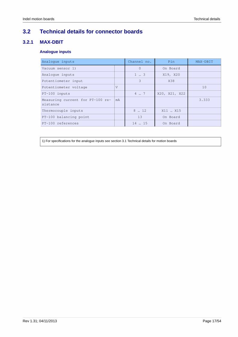
3.2 Technical details for connector boards
3.2.1 MAX-DBIT
Analogue inputs
Analogue inputs Channel no. Pin MAX-DBIT
Vacuum sensor 1) 0 On Board
Analogue inputs 1 … 3 X19, X20
Potentiometer input 3 X38
Potentiometer voltage V 10
PT-100 inputs 4 … 7 X20, X21, X22
Measuring current for PT-100 re-sistance
mA 3.333
Thermocouple inputs 8 … 12 X11 … X15
PT-100 balancing point 13 On Board
PT-100 references 14 … 15 On Board
Rev 1.31; 04/11/2013 Page 17/54
1) For specifications for the analogue inputs see section 3.1 Technical details for motion boards
Technical details Indel motion boards
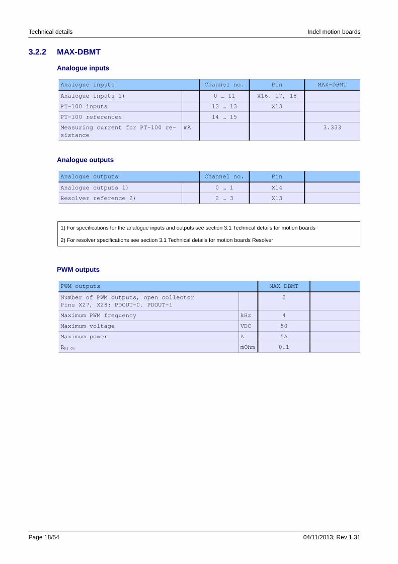
3.2.2 MAX-DBMT
Analogue inputs
Analogue inputs Channel no. Pin MAX-DBMT
Analogue inputs 1) 0 … 11 X16, 17, 18
PT-100 inputs 12 … 13 X13
PT-100 references 14 … 15
Measuring current for PT-100 re-sistance
mA 3.333
Analogue outputs
Analogue outputs Channel no. Pin
Analogue outputs 1) 0 … 1 X14
Resolver reference 2) 2 … 3 X13
PWM outputs
PWM outputs MAX-DBMT
Number of PWM outputs, open collector Pins X27, X28: PDOUT-0, PDOUT-1
2
Maximum PWM frequency kHz 4
Maximum voltage VDC 50
Maximum power A 5A
RDS ON mOhm 0.1
Page 18/54 04/11/2013; Rev 1.31
1) For specifications for the analogue inputs and outputs see section 3.1 Technical details for motion boards
2) For resolver specifications see section 3.1 Technical details for motion boards Resolver

Indel motion boards Technical details
3.3 Dimensions, pin assignment
3.3.1 Dimensions of AX4
A minimum distance of 50mm must be maintained between the individual motion boards.
Rev 1.31; 04/11/2013 Page 19/54
Fig. 2: AX4 front Fig. 1: AX4 side
Fig. 3: Drill plan, AX4
Technical details Indel motion boards
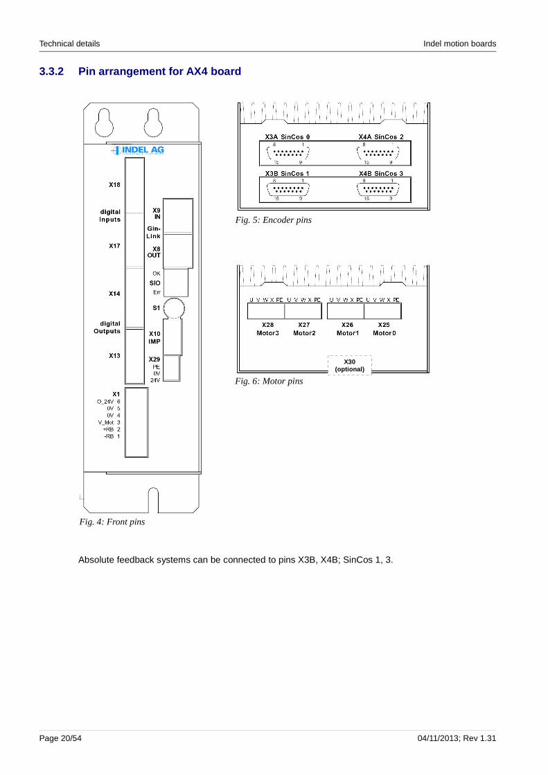
3.3.2 Pin arrangement for AX4 board
Absolute feedback systems can be connected to pins X3B, X4B; SinCos 1, 3.
Page 20/54 04/11/2013; Rev 1.31
Fig. 6: Motor pins
Fig. 5: Encoder pins
Fig. 4: Front pins
X30(optional)

Indel motion boards Technical details
3.3.3 Pin assignment for digital inputs and outputs in AX4
X13 1 O 0V Ground for 24V outputsDigital outputs 2 O OUT 0 Output 0
3 O OUT 1 Output 1
4 O OUT 2 Output 25 O OUT 3 Output 36 O OUT 4 Output 47 O OUT 5 Output 58 O OUT 6 Output 69 O OUT 7 Output 7
10 O 0V Ground for 24V outputs
X14 11 O 0V Ground for 24V outputsDigital outputs 12 O OUT 8 Output 8
13 O OUT 9 Output 9
14 O OUT 10 Output 1015 O OUT 11 Output 1116 O OUT 12 Output 1217 O OUT 13 Output 1318 O OUT 14 Output 1419 O OUT 15 Output 15
20 O 0V Ground for 24V outputs
X17 1 O 0V 24V GroundDigital inputs 2 I IN 0 Input 0
3 I IN 1 Input 1
4 I IN 2 Input 25 I IN 3 Input 36 I IN 4 Input 47 I IN 5 Input 58 I IN 6 Input 69 I IN 7 Input 7
10 O 24V 24V supply for sensors
X18 11 O 0V 24V GroundDigital inputs 12 I IN 8 Input 8
13 I IN 9 Input 9
14 I IN 10 Input 1015 I IN 11 Input 1116 I IN 12 Input 1217 I IN 13 Input 1318 I IN 14 Input 1419 I IN 15 External enabler for all axes
20 O 24V 24V supply for sensors
Rev 1.31; 04/11/2013 Page 21/54
Technical details Indel motion boards
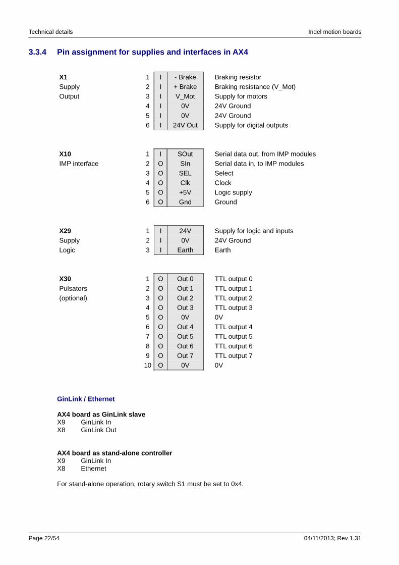
3.3.4 Pin assignment for supplies and interfaces in AX4
X1 1 I - Brake Braking resistor Supply 2 I + Brake Braking resistance (V_Mot)Output 3 I V_Mot Supply for motors
4 I 0V 24V Ground
5 I 0V 24V Ground6 I 24V Out Supply for digital outputs
X10 1 I SOut Serial data out, from IMP modulesIMP interface 2 O SIn Serial data in, to IMP modules
3 O SEL Select 4 O Clk Clock5 O +5V Logic supply6 O Gnd Ground
X29 1 I 24V Supply for logic and inputsSupply 2 I 0V 24V GroundLogic 3 I Earth Earth
X30 1 O Out 0 TTL output 0
Pulsators 2 O Out 1 TTL output 1(optional) 3 O Out 2 TTL output 2
4 O Out 3 TTL output 35 O 0V 0V6 O Out 4 TTL output 47 O Out 5 TTL output 5
8 O Out 6 TTL output 69 O Out 7 TTL output 710 O 0V 0V
GinLink / Ethernet
AX4 board as GinLink slaveX9 GinLink InX8 GinLink Out
AX4 board as stand-alone controllerX9 GinLink InX8 Ethernet
For stand-alone operation, rotary switch S1 must be set to 0x4.
Page 22/54 04/11/2013; Rev 1.31

Indel motion boards Technical details
3.3.5 Pin assignment for AX4 encoder systems
Pin Encoder type 1 Encoder type 2 Encoder type 3
X3A SinCos 0 Enc 0X3B SinCos 1 Enc 1 Absolute feedback system 1X4A SinCos 2 Enc 2X4B SinCos 3 Enc 3 Absolute feedback system 3
X3A, X4ASinCos InterfaceIncremental encoder interface
Pin 4 = +12V DCPin 12 = +5V DC
D-sub, 15-pole
Female
X3B, X4BSinCos Interface Incremental encoder interfaceSSI-Interface
Pin 4 = +12V DCPin 12 = +5V DC
D-sub, 15-poleFemale
Incremental encoder to absolute feedback inputs (pins X3B, X4B)
Incremental encoders can alsobe connected to the inputsfor the absolute feedbacksystem.
+IncA = Clk+
-IncA = Clk-
+IncB = Data+
-IncB = Data-
+Ref = Ref+
-Ref = Ref-
This type of connection allows you to achieve considerably higher signal frequencies for the encoder signals; see section 3.1 Technical details for motion boards, sub-section: Incremental encoder
In the case of AX boards, this function is available from HW Rev. B.
Rev 1.31; 04/11/2013 Page 23/54

Technical details Indel motion boards
Page 24/54 04/11/2013; Rev 1.31
Interruptions in the encoder and motor cables – whe n leading them into a cabinet or similar – should be designed with metal plug connections, not clamp connections.

Indel motion boards Technical details
Single-ended incremental encoders
Additional level adjustment is required if single-ended incremental encoders are being used. A connection must be made to the encoder interface at jacks X3A and X4A and to the absolute feedback interface at jacks X3B and X4B. Fig. 7 und Fig. 8 give an example for the absolute feedback interface. However, we generally recommend that you use increm ental encoders with a RS422 interface as per the current industry standard.
Rev 1.31; 04/11/2013 Page 25/54
Fig. 7: Connection example for 24V single-ended incremental encoder
Fig. 8: Connection example for 5V single-ended incremental encoder

Technical details Indel motion boards
3.3.6 Pin assignment for motors in AX4
3-phase motors Stepper motors
X25, X26, X27, X28 5 O Earth Shield Shield4 O X - Stepper motor L2-3 O W Phase W Stepper motor L1-2 O V Phase V Stepper motor L2+1 O U Phase U Stepper motor L1+
In order to operate 2 motors on the AX4 board, motors 0,1 and motors 2,3 must be switched in parallel: (direct view of motor pins)
3-phase motors in parallel operation
Motor 0 5 O EarthX25 4 O X
3 O W Motor X
2 O V Earth 5 Shield
1 O U - 4 -
W 3 Phase W
Motor 1 5 O Earth V 2 Phase V
X26 4 O X U 1 Phase U
3 O W2 O V
1 O U
Motor 2 5 O Earth
X27 4 O X3 O W Motor Y
2 O V Earth 5 Shield
1 O U - 4 -
W 3 Phase W
Motor 3 5 O Earth V 2 Phase V
X28 4 O X U 1 Phase U
3 O W
2 O V1 O U
Page 26/54 04/11/2013; Rev 1.31
In the case of parallel operation, the Y cables (fr om the motor pin to the junction of the parallel cables) must be at least 25 cm long. Otherwise, the output stages may be damaged.

Indel motion boards Technical details
Stepper motors in parallel operation
Motor 0 5 O EarthX25 4 O X
3 O W Motor X
2 O V Earth 5 Shield
1 O U L2- 4 Stepper motor L2-
L2+ 3 Stepper motor L2+
Motor 1 5 O Earth L1- 2 Stepper motor L1-
X26 4 O X L1+ 1 Stepper motor L1+
3 O W2 O V1 O U
Motor 2 5 O EarthX27 4 O X
3 O W Motor Y
2 O V Earth 5 Shield
1 O U L2- 4 Stepper motor L2-
L2+ 3 Stepper motor L2+
Motor 3 5 O Earth L1- 2 Stepper motor L1-
X28 4 O X L1+ 1 Stepper motor L1+
3 O W2 O V1 O U
Rev 1.31; 04/11/2013 Page 27/54
Technical details Indel motion boards
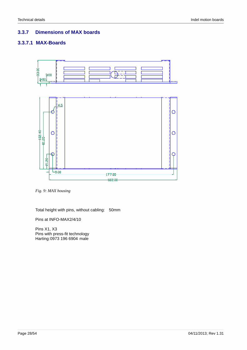
3.3.7 Dimensions of MAX boards
3.3.7.1 MAX-Boards
Total height with pins, without cabling: 50mm
Pins at INFO-MAX2/4/10
Pins X1, X3Pins with press-fit technologyHarting:0973 196 6904 male
Page 28/54 04/11/2013; Rev 1.31
Fig. 9: MAX housing

Indel motion boards Technical details
3.3.7.2 Connector board MAX2-DBIT
Dimensions of MAX2-DBIT
Vacuum sensor● Honeywell SDX15A2● Measuring range: 0 ... 15 psi● Full Scale: 90mV
PT-100 inputs4 PT-100 inputs at pins: X20, X21, X22The measuring current for PT100 resistance is 3.3333mA.
Motor enabler inputInput 15 (DI15, pin 30) at pin X37 is reserved for the motor enabler. All output stages are released by input 15.
Rev 1.31; 04/11/2013 Page 29/54
Fig. 10: MAX2-DBIT measurements

Technical details Indel motion boards
Thermocouple inputsThermocouple elements can be connected directly to pins X11 ... X15. There is a PT-100 balancing element on the connector board.● Relative accuracy 256 averages 15 bit● Absolute accuracy 45uV● Type T,U CU-constantan● Type J,L Fe-constantan● Type E,K Chromel-alumel● Type B,E,R Platinum-rhodium
Connection diagramPin assignment can be found in the file:Anschluss-Schema-MAX-DBIT.pdf
Power consumption with connector boardINFO-MAX2 with MAX2-DBIT 280 mAwithout load at analogue and digital outputs, without encoder
Pins on connector board MAX2-DBITPins X2, X3 Harting: 0903 296 6850 femalePins with press-fit technology on connector board
Companion piece on INFO-MAX2 Harting: 0973 196 6904 male
Pin X4, serial interface RS232 Compona 319 566 RJ12, 6p.Pins on connector board
Companion piece on serial cable Compona 327 266 RJ 12, 6p.
Pins X5 ... X8 Molex microFit 90130-1210 Header, 10 p.Encoder 1 ... 4, jack on connector board Arrow 245270
Companion piece on housing Molex microFit 90142-0010 10 p. femaleCrimp contacts Molex microFit 90119-2110 gold, AWG 22-24Crimp contacts Molex microFit 90119-2120 gold, AWG 26-28
Crimp-Tool Digikey 0638118700
Removal tool series CGRID Molex Digikey 69008-0003
Pins X9 ... X10 Tyco 609-1027
Encoder 1 ... 2, jack on connector board Arrow 341380
All information on pins is subject to correction.
Connection diagramPin assignment can be found in the file: Anschluss-Schema-MAX-DBIT.pdf
Page 30/54 04/11/2013; Rev 1.31

Indel motion boards Technical details
3.3.7.3 Connector board MAX4-DBIT
Dimensions of MAX4-DBIT
All pins as in MAX2-DBIT
Pins X25, X26, X40, X41 on connector board MAX4-DBITMotor pins Molex 43045 series 250V/5A
Arrow 43045-0612
Companion piece on cablePin housing Digikey 43025-0600
Crimp contacts Molex microFit 43030-0007 tin-plated
Extraction tool Micro-Fit, Pico-Blade Digikey 11-03-0043
Crimp-Tool Digikey 63819-0000
All information on pins is subject to correction.
Rev 1.31; 04/11/2013 Page 31/54
Fig. 11: MAX4-DBIT measurements
Technical details Indel motion boards
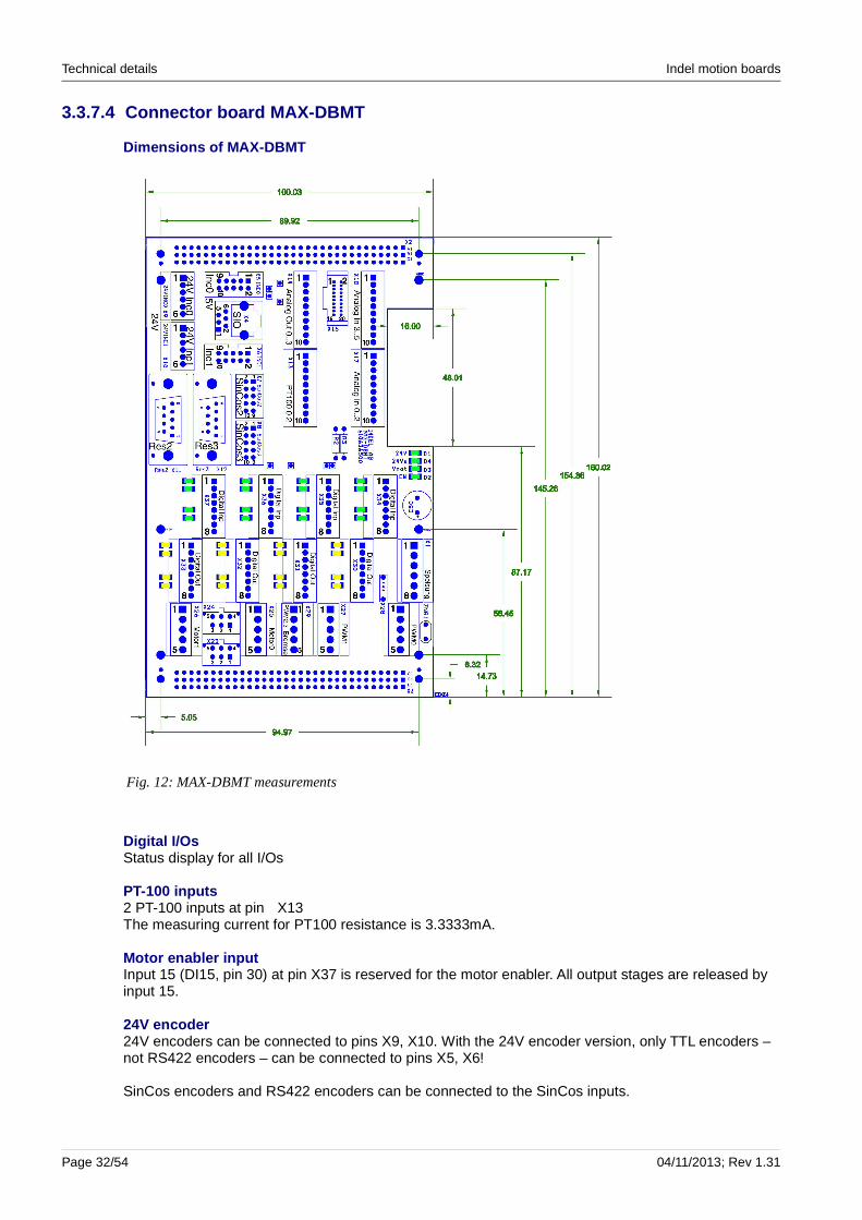
3.3.7.4 Connector board MAX-DBMT
Dimensions of MAX-DBMT
Digital I/OsStatus display for all I/Os
PT-100 inputs2 PT-100 inputs at pin X13The measuring current for PT100 resistance is 3.3333mA.
Motor enabler inputInput 15 (DI15, pin 30) at pin X37 is reserved for the motor enabler. All output stages are released by input 15.
24V encoder24V encoders can be connected to pins X9, X10. With the 24V encoder version, only TTL encoders – not RS422 encoders – can be connected to pins X5, X6!
SinCos encoders and RS422 encoders can be connected to the SinCos inputs.
Page 32/54 04/11/2013; Rev 1.31
Fig. 12: MAX-DBMT measurements

Indel motion boards Technical details
Thermocouple inputsThermocouple elements can be connected to pins X17 ... X18.● Relative accuracy: 256 averages 15 bit● Absolute accuracy 45uV● Type T,U CU-constantan● Type J,L Fe-constantan● Type E,K Chromel-alumel● Type B,E,R Platinum-rhodium
ResolverResolvers can be connected to pins X11, X12.
Analogue outputsAnalogue outputs 0 and 1 are free, analogue outputs 2 and 3 are reserved for the resolver reference and cannot be used.
PWM outputsLoads such as heating elements can be connected to pins X27, X27.● PWM voltage 48V● PWM power duration 3 ... 6A● PWM power max. 10A, resistant to short-circuiting
Power consumption with connector boardINFO-MAX2 with MAX-DBMT 450 mAwithout load at analogue and digital outputs, 16 LEDs on, without encoder
Pins on connector board MAX-DBMTPins X2, X3 Harting 0903 296 6850 femalePins with press-fit technology on connector board
Companion piece on INFO-MAX2 Harting 0973 196 6904 male
Pin X4, serial interface RS232 Compona 319 566 RJ12, 6p.Pins on connector board
Companion piece on serial cable Compona 327 266 RJ 12, 6p.
Pins X5 ... X6, encoders 0 ... 1 Tyco 609-1027Jack on connector board Arrow 341380
Pins X7 ... X8, SinCos 2, 3 Molex microFit 90130-1210 Header, 10-poleJack on connector board Spoerle 245270
Pins X9 ... X10, 24V incremental feedback encoder 0, 1Jack on connector board, 6-pole Phoenix 19 63 573 MCV 0.5/6-G-2.5 THT
Companion piece on encoder cable Phoenix 18 81 367 FK-MCP 1.5/6-ST-2.5
Pins X11 ... X12, resolvers 2, 3 Harting 0966 151 6512Jack on connector board D-SUB standing female 9-pole
For companion pieces see MAX-DBIT
Connection diagramPin assignment can be found in the file: Anschluss-Schema-MAX-DBMT.pdf
All information is subject to correction.
Rev 1.31; 04/11/2013 Page 33/54

Technical details Indel motion boards
3.3.7.5 GinLink, ethernet connections
MAX4 board as GinLink slave
X40 GinLink InX41 GinLink Out
MAX4 board as stand-alone controller
X40 GinLink InX41 Ethernet
For stand-alone operation, rotary switch S1 must be set to 0x4.
Page 34/54 04/11/2013; Rev 1.31
Fig. 13: GinLink, ethernet pins
Indel motion boards Technical details
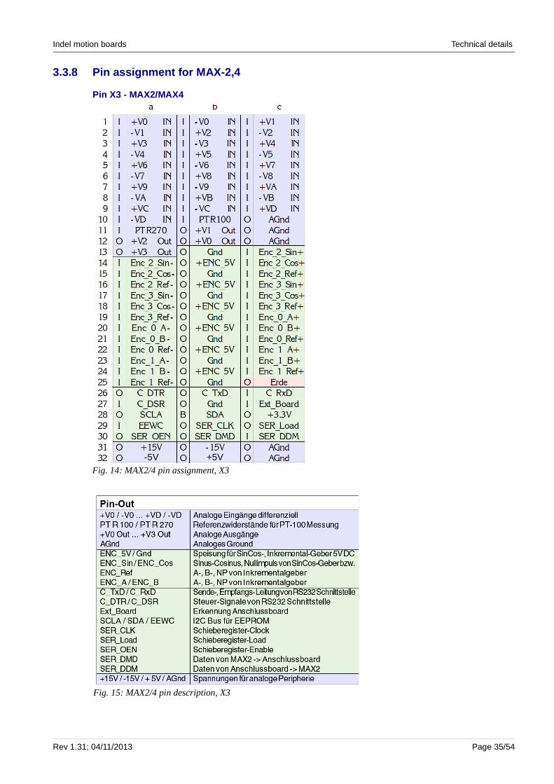
3.3.8 Pin assignment for MAX-2,4
Pin X3 - MAX2/MAX4
Rev 1.31; 04/11/2013 Page 35/54
Fig. 14: MAX2/4 pin assignment, X3
Fig. 15: MAX2/4 pin description, X3
+5V-5V

Technical details Indel motion boards
3.3.9 Pin assignment for MAX-2
Pin X1 - MAX2
Page 36/54 04/11/2013; Rev 1.31
Fig. 16: MAX 2 pin assignment, X3
Fig. 17: MAX2 pin description, X
Indel motion boards Technical details
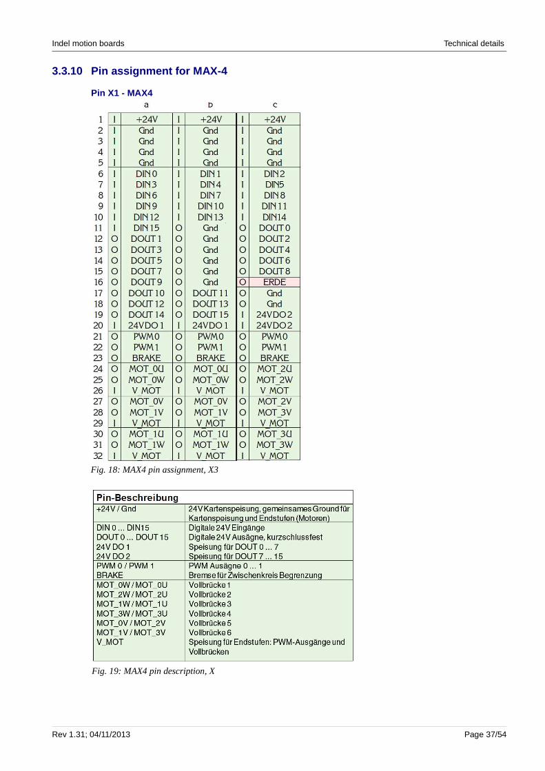
3.3.10 Pin assignment for MAX-4
Pin X1 - MAX4
Rev 1.31; 04/11/2013 Page 37/54
Fig. 18: MAX4 pin assignment, X3
Fig. 19: MAX4 pin description, X
Technical details Indel motion boards
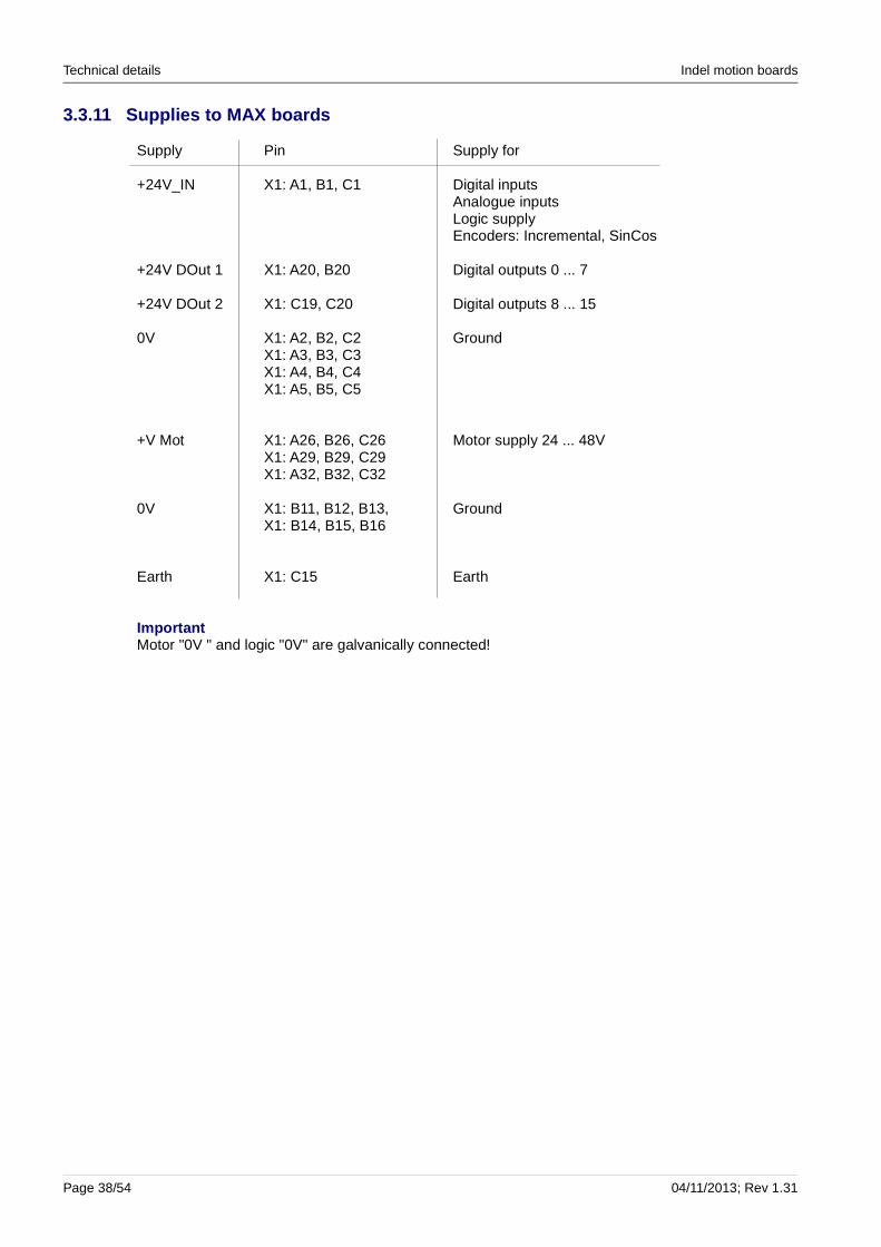
3.3.11 Supplies to MAX boards
Supply Pin Supply for
+24V_IN X1: A1, B1, C1 Digital inputsAnalogue inputsLogic supplyEncoders: Incremental, SinCos
+24V DOut 1 X1: A20, B20 Digital outputs 0 ... 7
+24V DOut 2 X1: C19, C20 Digital outputs 8 ... 15
0V X1: A2, B2, C2 GroundX1: A3, B3, C3X1: A4, B4, C4X1: A5, B5, C5
+V Mot X1: A26, B26, C26 Motor supply 24 ... 48VX1: A29, B29, C29X1: A32, B32, C32
0V X1: B11, B12, B13, GroundX1: B14, B15, B16
Earth X1: C15 Earth
ImportantMotor "0V " and logic "0V" are galvanically connected!
Page 38/54 04/11/2013; Rev 1.31
Indel motion boards Serial interface
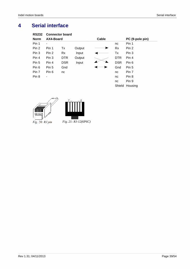
4 Serial interface
RS232 Connector boardNorm AX4-Board Cable PC (9-pole pin)Pin 1 - nc Pin 1
Pin 2 Pin 1 Tx Output Rx Pin 2
Pin 3 Pin 2 Rx Input Tx Pin 3
Pin 4 Pin 3 DTR Output DTR Pin 4
Pin 5 Pin 4 DSR Input DSR Pin 6
Pin 6 Pin 5 Gnd Gnd Pin 5Pin 7 Pin 6 nc nc Pin 7
Pin 8 - nc Pin 8nc Pin 9Shield Housing
Rev 1.31; 04/11/2013 Page 39/54
Fig. 21: RJ-12(6P6C)

Connection examples Indel motion boards
5 Connection examples
5.1 Motors on MAX2 board
Page 40/54 04/11/2013; Rev 1.31
Fig. 22: Connection example for AC servo motor 1
VW
U
Distribution Board
U
INFO-MAX2 Board
MOT_2A
X25
PHOENIX MCV 1937635, 5 POL.
12345
12345
X1 a25, b25, c25 FRAME
Cable
SHIELD
MOT_1A
WMOT_1BV
AC-Servo Motor 1
SHIELD
X1 a24, b24, c24X1 a27, b27, c27
FRAME
AC-Motor3-phase
Fig. 24: Connection example for AC servo motor 2
V
X1 a31, b31, c31
SHIELD
X1 a28, b28, c28X1 a30, b30, c30
X26
PHOENIX MCV 1937635, 5 POL.
12345
12345
FRAMEW
U
SHIELD
Cable
MOT_3A
AC-Motor3-phase
MOT_3BFRAME
MOT_2BUVW
AC-Servo Motor 2
INFO-MAX2 Board Distribution Board
Fig. 23: Connection example for DC motor 1
FRAME
X1 a24, b24, c24
Motor -
Motor +
X1 a25, b25, c25
X25
PHOENIX MCV 1937635, 5 POL.
12345
12345
Distribution Board
SHIELD
INFO-MAX2 Board
MOT_1A
FRAMESHIELD
Motor +
DC-Servo Motor 1
Motor - DC-Motor
Cable
MOT_1B
Fig. 25: Connection example for DC motor 2
X26
PHOENIX MCV 1937635, 5 POL.
12345
12345
Distribution Board
Motor +Motor +
FRAMEMOT_3B
FRAMEMotor -
INFO-MAX2 Board
DC-Motor
Cable
SHIELD
X1 a31, b31, c31
SHIELD
MOT_3AX1 a30, b30, c30
Motor -
DC-Servo Motor 2

Indel motion boards Connection examples
2-phase stepper motors with Ucc/2: As there are 3 outputs available per motor, one end of both coils must be connected to a shared output in the case of a 2-phase stepper motor.
This shared connection is raised to 24V by the motor control. The two other ends of the coils are each wired to a free output. This allows a 48V motor to be operated at max. 24V.
Rev 1.31; 04/11/2013 Page 41/54
Fig. 26: Connection example for PWM output 1
FRAME
Load +
Distribution Board
Load +Load -
INFO-MAX2 Board
FRAME
Cable
LoadPWM_1
X1 a21, b21, c21
SHIELD
X1 a1, b1, c1+24V
Load -
PWM-Output 1
X27
PHOENIX MCV 1937619, 3 POL.
11
22
33
Fig. 27: Connection example for PWM output 2
Distribution Board
Load -X1 a22, b22, c22
Load +
Cable
Load -
SHIELD
PWM-Output 2
FRAME
X1 a1, b1, c1 Load +PWM_2
LoadFRAME
INFO-MAX2 Board
+24VX28
PHOENIX MCV 1937619, 3 POL.
11
22
33
Fig. 28: Connection example for brake
BRAKE +BRAKEV_MOT
X29
PHOENIX MCV 1937619, 3 POL.
11
22
33
Distribution Board
FRAMEBRAKE -X1 a23, b23, c23 FRAME
CableINFO-MAX2 Board
BRAKE -
Brake
BRAKE +X1 a26/29, b26/29, c26/29BRAKE
SHIELD
Fig. 29: Connection example for stepper motor 1
FRAME
Stepper Motor 1
Distribution Board
FRAME
X1 a24, b24, c24
SHIELD
U
WV
INFO-MAX2 Board
SHIELD
StepperMotor2-phase
Cable
X1 a25, b25, c25 WMOT_1BX1 a27, b27, c27
MOT_1AMOT_2A
UX25
PHOENIX MCV 1937635, 5 POL.
11
22
33
44
55
V
2L1
L11L1
1L2
2L2
L2
24V Stepper Motor

Connection examples Indel motion boards
5.2 Wiring of digital inputs and outputs
The wiring of the digital inputs and outputs is identical on all MAX boards and AX4 boards:
Page 42/54 04/11/2013; Rev 1.31
Fig. 30: Wiring of digital inputs
Din
2.2nF
22k
74LV165
8
1112
16
1314
GND
D0D1
VCC
D2D34k
7
1nF
74LV141 2
+3.3V
Fig. 31: Wiring of digital outputs
ITS724
GN
D2
OUT118
OUT217
OUT314
OUT413
Vbb
1
Dout
+24V
1nF
Indel motion boards Installation
6 Installation
AssemblyAssembly must be carried out according to the documentation and using suitable tools. The devices must only be assembled when switched off. When carrying out wiring work on the drive, the control cabinet must be secured against reactivation. National accident prevention regulations must be complied with. Electrical installation must be carried out in accordance with national provisions (wire colours, cross-sections, fuses, protective earth connection, etc.).
Card supplyA regulated 24V supply with sufficient reserve capacity is recommended for the power supply to the card. The 24V supply must be equipped with a mains filter.
Shielded cablesThe resolver and SinCos interface signals are extremely susceptible to interference, meaning that these lines are equipped with a pair-twisted and double shielded cable.The INC encoder and serial interface, as well as the motor cable, must be shielded cables!
The motor cables must be placed on an uncoated metallic base plate with a bracket with all-round contact in front of the motion board.
Also see “Indel-Verdrahtungsrichtlinie.pdf”
Potential equalisationApply all shielding on both sides. You may need to use a potential compensator in order to avoid unwanted leakage currents over the shielding, particularly in the case of larger distances or different supplies. See “Indel wiring guidelines”.
Shield railThe control cabinet must include a shield rail, to which all shielded cables can be attached. Metallic pins with all-round contact with the shielding are also suitable for cable insertion.
The motor boards must be assembled on the assembly plate with good conductivity. All shielded cables must be shielded on both sides.
Plug-in connectionsInterruptions in the resolver and motor cables – when leading them into a cabinet or similar – should be designed with metal plug connections, not clamp connections. This ensures that the cable shielding is not interrupted unnecessarily.
Inputs and outputsThe additional digital inputs and outputs can only be wired within the control cabinet. If the cabling is longer than 1m, these inputs and outputs must also be equipped with shielding.
Motor temperature The motor temperature can be measured using either a bi-metal switch (T-switch) in the motor or an NTC (MTemp). The bi-metal switch can only be wired with the motor cables. The NTC can only be wired in the resolver cables. (Insulation class!)
Rev 1.31; 04/11/2013 Page 43/54

Installation Indel motion boards
Cabling The motor cable must be laid separately from the signal and network cables. Motor cables must not lead over clamps; if necessary, use metallic plug connectors. The shielding must be attached with all-round contact in the pin.
Also see Indel wiring guidelines and INDEL setup guidelines.
Protective earth connection (PE)The protective earth must be designed in accordance with EN 61800-5-1:
Cross-section of the outer conductor [mm2]
Minimum cross-section of the correspon-ding protective earth conductor S p [mm2]
S ≤ 16 S
16 < S ≤ 16 16
35 < S S/2
Table 6.1
Protective earth conductors that are not part of a cable must have a minimum cross-section of 4mm2.
Mains filterThe power supply must be equipped with a filter. The optimum filter and placement may need to be defined by means of an emission measurement as the emitted interference is dependent upon the motor cable length, among other things. Without correctly dimensioned filters, the product may cause very frequent interference.
6.1 Cooling and ventilation
Sufficient measures must be taken to ensure that the temperature in the control cabinet does not exceed the specified maximum. Fans or air conditioning units must therefore be placed in suitable locations inside the control cabinet.
If air conditioning units are being used, it must be ensured that excessively low temperatures do not cause condensation.
Page 44/54 04/11/2013; Rev 1.31
Cold air exiting the air conditioning unit must be prevented from blowing directly onto the housing of a servo drive. In unfortunate cases, particularly where humidity i s high, this can lead to condensation on the inside of the device.
Indel motion boards Installation
6.1.1 Notes on UL directive
Motor overload protectionExternal motor overload protection must be provided by the user.
Additional overload protection is provided for motors by means of temperature sensors in the field winding. The user is responsible for applying this overload protection.
Only use UL-certified copper wires for 75°C.
UL fuses and cable cross-sectionsThe controller requires a fuse in the supply line. Only use UL-certified fuses and holders. Triggering characteristic “K”.
Safety Cablefuse cross-sectionA mm2 AWG
5 1 1710 1 1725 6 925 6 9
Manufacturers of UL-certified safety fuses:
● FS Ferraz Shawmut● Limitron KTK from Bussmann
6.1.2 Braking resistanceThere is no braking resistor on the MAX2 board. The external braking resistor must be secured against thermal overload.
Supply: 48VBallast 0% Ucc = 50VBallast 100% Ucc = 52V
Supply: 24VBallast 0% Ucc = 25VBallast 100% Ucc = 27V
For resistance values for the braking resistor see technical details.
Rev 1.31; 04/11/2013 Page 45/54

Operation Indel motion boards
7 Operation
7.1 Braking resistor
It is highly recommended that a braking resistor be used on all motion boards.e.g. 150 Ohm 2W for minimum braking energy destruction.
The braking resistance must be dimensioned in accordance with the application.
7.2 Motion boards with an ethernet interface
The following conditions must be met in order to be able to speak to the MAX-2,4,10 motion boards or the AX4 board via the ethernet interface:
● Ethernet communication must run at 1GHz. In addition, a 1GBit-enabled switch can also be used in order to use PCs or laptops with a 100MBit interface
● The address switch on the motion board must be set to 0x4● The GinLink pin Gin-Out is used for the ethernet connection
Page 46/54 04/11/2013; Rev 1.31

Indel motion boards Fieldbus systems
8 Fieldbus systems
8.1 GinLink
● GHz fieldbus, max. 32kHz cycle time ● Ethernet, up to 100m segment length ● GinLink frames packed into ethernet frames ● Standard ethernet frames: PowerLink, EtherCat cameras ● Deterministic transmission ● Jitter <70ns
Number Sampling-Rate Data
Axes 90 16kHz 4 x 32 Bit
Digital Inputs 12000 8kHz 1 Bit
Digital Outputs 12000 8kHz 1 Bit
Analog Inputs 720 8kHz 16 Bit
Analogue outputs 720 8kHz 16 Bit
Communication
Slave to Master 1 8kHz 11.5 MByte/s
Slave to Slave 1 8kHz 11.5 MByte/s
Standard Ethernet frames 2 8kHz 23.0 MByte/s
Rev 1.31; 04/11/2013 Page 47/54
0 100 200 300 400 500 600 700 800 900 1000
Transmission Rate MHz
Can-Bus
Profibus
Sercos
INFO-Link
100MBit Ethernet
GinLink
Fiel
dbus
125us
Slot 0
15.63us
Slot 1 Slot 7
8kHz
INCO-Frame
Master-Slave Kommuni-
kation
8kHz
Slave- SlaveKommuni-
kation
8kHz
Freies Frame
=
100MBit Ethernet
16kHz
High-SpeedFrame
z.B.90 Achsen
8kHz
12'000 Input
12'000 Output
16kHz
High-SpeedFrame
z.B.90 Achsen
Ful
l Eth
erne
t Fra
me
1536
Byt
es
31.25us 46.88us 62.5us 78.13us 93.75us 109.4us
8kHz
0us
Slot 2
Ethernet-Header
IP-Header
UDP-Header
Gin-Header
Gin-Frame 1
Gin-Frame 2
Gin-Frame 3
Gin-Frame 4
Gin-Frame n
CRC
8kHz
720 analogeInputs
720 analoge Outputs

Fieldbus systems Indel motion boards
8.2 INFO-Link
Addressing (blue)
S1 Low 0x00 0x01 0x02 0x03 0x04
Axis 0 00 10 20 30 40Encoder 1 01 11 21 31 41Axis 2 02 12 22 32 42Encoder 3 03 13 23 33 43PWM 0PWM 1Digital Output 0...15 16..31Digital input 0 ... 15 16..31Analogue input 0 ... 13 14..25Analogue output 0 ... 3 4 ... 7
LEDs on the receiver module
Power = +5V supplyRec = INFO-link receiver-signal OK
Transmitting power jumper (green)The jumpers influence the brightness of the transmitting LEDs, and therefore the segment length of the fibre cable to the next card.
Segment lengthJumper position
0 ... 10m no jumper8 ... 30m 10 ... 30 m20 ... 50m 30 ... 50 m
Page 48/54 04/11/2013; Rev 1.31
Fig. 32: MAX equipment
Indel motion boards Fieldbus systems
8.3 Error messages
Stop, deactivated 0x0000'0001Ucc below Ucc min 0x0000'0002Ucc above Ucc max 0x0000'0004 I2t exceeded > 120% 0x0000'0008
Output stage overheated 0x0000'0010Motor temp exceeded 0x0000'0020Motor short-circuit / IGBT protection 0x0000'0040Resolver SinCos error 0x0000'0080
Maximum rotational speed exceeded 0x0000'0100Safety relay not switched on 0x0000'0200Auto-commutation error 0x0000'0400Power end stop reached 0x0000'0800
Phase error 0x0000'1000PWM watchdog: Interrupt overrun 0x0000'2000missing Exteral Enable 0x0000'4000missing (Motor) configuration 0x0000'8000
Feldbus Watchdog 0x0001'0000
8.4 Warnings
Ucc below Ucc ok 0x0000'0001Ucc is set up and OK 0x0000'0002Warning Iq_max reached 0x0000'0004
Warning output phase hot 0x0000'0010Warning I2t exceeded 0x0000'0020Motor temp exceeded 0x0000'0040100% modulation exceeded 0x0000'0080
Warning unloading time exceeded 0x0000'0100
Rev 1.31; 04/11/2013 Page 49/54

Sales and service Indel motion boards
9 Sales and service
9.1 Manufacturer
Indel AGTüfiwis 26CH-8332 RussikonSwitzerland
Tel. +41 / 44 956 20 00Fax +41 / 44 956 20 09
9.2 Maintenance, cleaning, repair
The Indel servo drives are maintenance-free. Any warranty shall expire if the housing is opened.
Do not submerge or spray the housing. In the event of contamination inside the unit: have it cleaned by the manufacturer.
Repairs can only be carried out by authorised specialist personnel. Any warranty on the part of Indel shall expire in the event of unauthorised intervention.
9.3 Transport and storage
When storing, please consider the effect of the ambient conditions: avoid impermissible stresses such as mechanical load, temperature, moisture, aggressive atmospheres.
9.4 Disposal
The Indel servo drives are made of various materials: steel housing, aluminium heat sinks, electronic board
The individual components must be disposed of properly. All Indo servo drives can be returned to Indel AG for proper disposal. The sender shall bear the costs of transport.
Page 50/54 04/11/2013; Rev 1.31

Indel motion boards Sales and service
9.5 Declaration of conformity
Rev 1.31; 04/11/2013 Page 51/54

Sales and service Indel motion boards
Page 52/54 04/11/2013; Rev 1.31

Indel motion boards List of figures
10 List of figures
Fig. 1: AX4 side........................................................................................................................19Fig. 2: AX4 front.......................................................................................................................19Fig. 3: Drill plan, AX4..............................................................................................................19Fig. 4: Front pins.......................................................................................................................20Fig. 5: Encoder pins..................................................................................................................20Fig. 6: Motor pins......................................................................................................................20Fig. 7: Connection example for 24V single-ended incremental encoder..................................25Fig. 8: Connection example for 5V single-ended incremental encoder....................................25Fig. 9: MAX housing................................................................................................................28Fig. 10: MAX2-DBIT measurements.......................................................................................29Fig. 11: MAX4-DBIT measurements........................................................................................31Fig. 12: MAX-DBMT measurements.......................................................................................32Fig. 13: GinLink, ethernet pins.................................................................................................34Fig. 14: MAX2/4 pin assignment, X3.......................................................................................35Fig. 15: MAX2/4 pin description, X3.......................................................................................35Fig. 16: MAX 2 pin assignment, X3.........................................................................................36Fig. 17: MAX2 pin description, X............................................................................................36Fig. 18: MAX4 pin assignment, X3..........................................................................................37Fig. 19: MAX4 pin description, X............................................................................................37Fig. 20: RJ pin...........................................................................................................................39Fig. 21: RJ-12(6P6C)................................................................................................................39Fig. 22: Connection example for AC servo motor 1.................................................................40Fig. 23: Connection example for DC motor 1..........................................................................40Fig. 24: Connection example for AC servo motor 2.................................................................40Fig. 25: Connection example for DC motor 2..........................................................................40Fig. 26: Connection example for PWM output 1......................................................................41Fig. 27: Connection example for PWM output 2......................................................................41Fig. 28: Connection example for brake.....................................................................................41Fig. 29: Connection example for stepper motor 1.....................................................................41Fig. 30: Wiring of digital inputs................................................................................................42Fig. 31: Wiring of digital outputs..............................................................................................42Fig. 32: MAX equipment..........................................................................................................48
Rev 1.31; 04/11/2013 Page 53/54
Document status Indel motion boards
11 Document status
DisclaimerNo guarantee is made for the correctness or completeness of the information provided. Subject to technical changes.
File-History1.15 29.04.2011 Disclaimer
. AX4: X10 and GinLink pin described; MAX boards: GinLink pin described1.16 13.05.2011 AX-4: parallel switching of output stages1.17 17.05.2011 AX-4: Encoder-Stecker für SinCos, Encoder, SSI1.18 23.05.2011 Missing links to images, address switch Gin-MAX2,41.19 07.06.2011 Technical details for connector boards1.22 30.09.2011 Disclaimer added1.23 21.11.2011 Correction of +/-5V in Fig. 14: +5V to 32b -5V to 32a
Inc correction to absolute feedback inputs: IncA to Clk, IncB to Data1.24 31.01.2012 AX4 with resolver option removed, pin assignment for AX4 phase U and V corrected1.25 21.02.2012 Connection example for 5V/24V single-ended inc encoder1.26 27.04.2012 Correction: in stand-alone operation of MAX4 and AX4, GinLink Out becomes the ethernet
interface1.27 27.04.2012 Document status section added1.28 21.12.2012 Note on RS422 with 120 Ohm completed. The encoder must be able to deal with this load
Ax4 5V supply for encoders from 200mA to 800mA (all encoders together)1.29 25.06.2013 Expansion of section 3.3.6 Pin assignment for motors in AX4. Connection of stepper motors and
3-phase motors in parallel operation (GIN-Ax4 2x10A)1.30 26.09.2013 Expansion of section 3.3.6 Pin assignment for motors in AX4 Minimum length for Y cables in
parallel operation1.31 04.11.2013 Chapter 3.1 add tip for additional cooling measures to keep the ambient temperature below 40°C.
Increase the minimum distance between servo drives to 50mm
Page 54/54 04/11/2013; Rev 1.31


