13
Special Report HARDWARE SAFETY Sponsored by
2009
Special Report
HaRdwaReSafety
Sponsored by

watch Out with Piping, Valves and HosesConsider common dangers during process hazard analysis.
By Ian Sutton, AMEC Paragon
PROceSS Safety management standards require plant managements to identify and address hazards. While every site poses unique risks, many hazards to do with piping, valves and hoses really don’t differ much from one facility to another. There-fore, to save time during process hazard analysis (PHA) and improve the quality of the evaluation, it’s useful to point out common dangers before PHA meetings start.
So, in this article, I’ll provide some guidance about the nature of these hazards.
PiPing
Hazards associated with piping are particularly com-mon with:
• hydraulic hammer;• pig launcher and receivers;• pressure in relief headers;• overload of overhead vacuum lines; and• underground piping. Hydraulic hammer.Suddenly stopping or starting
a liquid flow causes this phenomenon. If the valve in a line containing liquid is closed quickly, the entire volume of liquid in the line up to that valve is stopped quickly. The effect is to create a sudden pressure surge that can damage instruments and valves and, in
extreme cases, cause the pipe to burst. Hammer can occur in lines containing process
vapors or low pressure steam. If the vapor or steam cools as it flows down the line, liquid forms in the lower section of the line and then flows with the gas or steam. Eventually the amount of liquid can become so great that it blocks the line in the same way that a valve would, thus creating the potential for hammer.
If hydraulic hammer is considered a potential problem and the valve is automatically actuated, the PHA team should think about recommending putting a restriction in the vent line from the actuator. This restriction would prevent the valve from closing too quickly.
Pig launchers and receivers. Use of pig launch-ers and receivers inherently poses hazards because process piping must be opened to the atmosphere and operators must be in the area (to insert and remove the pigs). Three risks require particular attention:
1. Operators and maintenance personnel face the potential of being exposed to large quantities of toxic or flammable materials if pigging equip-ment is prematurely opened.
2. If the operation isn’t properly conducted, the pig could accidentally shoot out of the launcher or receiver.
2
3
3. For larger lines, lifting a pig to put it into a launcher (or to remove it from a receiver) leads to the possibility of it being dropped onto someone or something.
You can ameliorate these hazards by using interlock systems and operating procedures that don’t allow the pig trap/receiver door to be open while the system is under pressure. Also, you can minimize risks of pigs impacting people or equipment by locat-ing the trap/receiver away from normal operations and pointing doors toward a safe location.
Pressure in relief headers. Relief valves open at a set pressure. However, it’s important to realize that it’s differential pressure that actually causes the valve to open. Therefore, if the set point for a relief valve is, say, 50 psig, and pressure in the relief header is 10 psig, the relief valve will open when absolute pressure in the vessel it’s protecting is 60 psig. Such a scenario could occur if a plant-wide upset leads to multiple vessels discharging into the relief header simultane-ously.
To get around this difficulty, some relief valves are designed to open at a specified absolute pressure. The PHA team should check which approach is be-ing used and consider implications of multiple relief valves opening simultaneously (such as would happen if there were a large fire on the unit).
Overload of overhead vacuum lines. High capacity vacuum distillation columns typically have very large diameter overhead lines from the top of the column to the condenser because available pressure drop is so small. Because the system pressures are so low the piping wall can be quite thin. Therefore, if the line inadvertently is filled with liquid (either process fluids during a column upset or water during hydrotesting), the lines could collapse.
The PHA team should check the pressure rating for the overhead pipe and confirm its supports can handle a liquid-full situation. If they can’t, you must take special precautions to ensure the column can’t overflow. Also, a procedure for safely pressure testing
the system with gas has to be developed and followed. Underground piping. Such lines can be hazard-
ous because not much may be known about their condition — “out of sight, out of mind.” Unusually high corrosion rates may afflict piping if a cathodic protection system wasn’t installed. Contamination of ground water or some other pollution event may provide first indication of a problem.
PHA team members should satisfy themselves that underground piping is properly inspected and maintained.
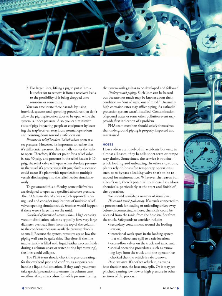
HOSeS
Hoses often are involved in accidents because, in almost all cases, they handle short-term or tempo-rary duties. Sometimes, the service is routine — truck loading and unloading. In other situations, plants rely on hoses for temporary operations, such as to bypass a leaking valve that’s to be re-moved for maintenance. Whatever the reason for a hose’s use, there’s potential to release hazardous chemicals, particularly at the start and finish of the operation.
You should consider a number of situations: Hoses and truck pull-away. If a truck connected to
a process tank for loading or unloading drives away before disconnecting its hose, chemicals could be released from the tank, from the hose itself or from the truck. Safeguards to consider include:
• secondary containment around the loading station;
• intentional weak spots in the loading system that will direct any spill to a safe location;
• excess-flow valves on the truck and tank; and• special operating procedures, such as remov-
ing keys from the truck until the operator has checked that the vehicle is safe to move.
Hose run over. If another vehicle runs over a hose that’s in use, the hose may split. Or it may get pinched, causing low flow or high pressure in other sections of the process.
4
Hose failure. Frequent use of hose can lead to flexing and abrasion and eventual failure. So, hoses require careful inspection and maintenance — and prompt replacement when necessary. The team should check that hoses to be stored outside couldn’t be dam-aged by water, freezing or sunlight.
Backflow prevention. When utility hoses are connected to a process, it’s particularly important to make sure that a backflow preventer (check valve) is installed. Otherwise hazardous chemicals may reverse flow through the hose into another operating area.
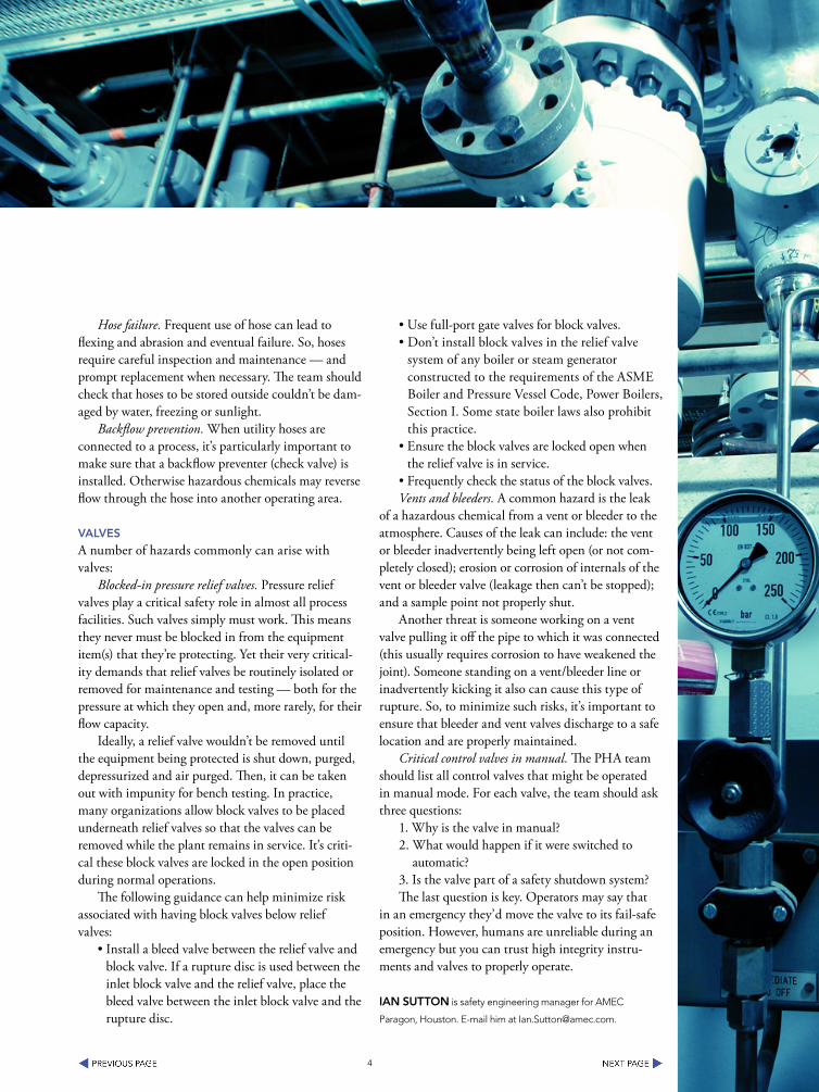
ValVeS
A number of hazards commonly can arise with valves:
Blocked-in pressure relief valves. Pressure relief valves play a critical safety role in almost all process facilities. Such valves simply must work. This means they never must be blocked in from the equipment item(s) that they’re protecting. Yet their very critical-ity demands that relief valves be routinely isolated or removed for maintenance and testing — both for the pressure at which they open and, more rarely, for their flow capacity.
Ideally, a relief valve wouldn’t be removed until the equipment being protected is shut down, purged, depressurized and air purged. Then, it can be taken out with impunity for bench testing. In practice, many organizations allow block valves to be placed underneath relief valves so that the valves can be removed while the plant remains in service. It’s criti-cal these block valves are locked in the open position during normal operations.
The following guidance can help minimize risk associated with having block valves below relief valves:
• Install a bleed valve between the relief valve and block valve. If a rupture disc is used between the inlet block valve and the relief valve, place the bleed valve between the inlet block valve and the rupture disc.
• Use full-port gate valves for block valves. • Don’t install block valves in the relief valve
system of any boiler or steam generator constructed to the requirements of the ASME Boiler and Pressure Vessel Code, Power Boilers, Section I. Some state boiler laws also prohibit this practice.
• Ensure the block valves are locked open when the relief valve is in service.
• Frequently check the status of the block valves. Vents and bleeders. A common hazard is the leak
of a hazardous chemical from a vent or bleeder to the atmosphere. Causes of the leak can include: the vent or bleeder inadvertently being left open (or not com-pletely closed); erosion or corrosion of internals of the vent or bleeder valve (leakage then can’t be stopped); and a sample point not properly shut.
Another threat is someone working on a vent valve pulling it off the pipe to which it was connected (this usually requires corrosion to have weakened the joint). Someone standing on a vent/bleeder line or inadvertently kicking it also can cause this type of rupture. So, to minimize such risks, it’s important to ensure that bleeder and vent valves discharge to a safe location and are properly maintained.
Critical control valves in manual. The PHA team should list all control valves that might be operated in manual mode. For each valve, the team should ask three questions:
1. Why is the valve in manual?2. What would happen if it were switched to
automatic?3. Is the valve part of a safety shutdown system?The last question is key. Operators may say that
in an emergency they’d move the valve to its fail-safe position. However, humans are unreliable during an emergency but you can trust high integrity instru-ments and valves to properly operate.
ian SuttOn is safety engineering manager for AMEC
Paragon, Houston. E-mail him at [email protected].

5
Repair your Mechanical integrity ProgramMany plants find it difficult to address a number of crucial issues.
By Michael J. Hazzan, Chemetica, Inc./AcuTech Consulting Group
tHe MecHanical integrity (MI) element of the U.S. Occupational Safety and Health Administra-tion’s Process Safety Management (PSM) Standard [29 CFR 1910.119(j)] has been difficult for many fa-cilities to implement. Indeed, PSM audits by OSHA have consistently demonstrated that MI accounts for a large number of citations at most facilities. In some cases, it has been the last PSM element to be fully addressed.
This is not to say that inspection, testing and pre-ventive maintenance (ITPM) programs do not exist at PSM-covered facilities nor that the maintenance pro-grams can be characterized as “breakdown only.” The chemical industry has used preventive and predictive maintenance programs for many years. What have been lacking in some cases are complete integrated MI-management-system programs that address all of the sub-elements of MI as defined in the PSM Stan-dard. There are several reasons for this situation:
The MI element of the PSM regulations is written in very broad performance-based language – even more so than the remainder of the Standard. Inter-pretation of these broadly stated MI requirements and the matching of these requirements to actual facility
policies, practices and procedures can be a difficult process.
Some companies interpret MI to mean only pre-ventive maintenance and therefore assign MI solely to the maintenance group. Actually, because MI includes a wide variety of tasks and activities, the responsibili-ties for MI activities are spread widely across a facility and many personnel may not realize that their jobs involve a portion of a regulated MI program.
MI activities encompass the entire lifecycle of the covered equipment, including engineering, construc-tion and spare parts, not just the ongoing mainte-nance activities; therefore some of the requirements of the MI element may not be completely implemented.
Currently, there is no overall industry-published consensus guidance on establishing and implement-ing a MI program (although the American Institute of Chemical Engineers’ Center for Chemical Process Safety plans to issue a comprehensive guidelines book in 2005).
This article will explore these issues, including the interpretation aspects that confound some sites, the responsibilities of various plant groups for executing MI activities and typical weaknesses in MI programs.

6
Mi ReQuiReMentS
The PSM Standard states in 29 CFR 1910.119(j)(1) that the MI element is applicable to the following process equipment:
• pressure vessels and storage tanks; • piping systems (including piping components
such as valves); • relief and vent systems and devices; • emergency shutdown systems; • controls (including monitoring devices and
sensors, alarms and interlocks); and• pumps.OSHA’s wording of the standard may have
caused some confusion because it appears to be an incomplete list of equipment. Most of the equipment types listed above are self-explanatory. However, several clarifications are appropriate:
Pressure vessels that are not registered vessels and are operated at less than 15 psig should also be included in the MI program if they contain PSM-covered materials.
Heat exchangers are either pressure vessels or components in a piping system and therefore should be part of the MI program if they cool or heat PSM-covered materials.
Piping system components include any me-chanical device that is installed in-line in the piping system and is exposed to PSM-covered materials inside the piping — e.g., filters, strainers, flanges, gasket materials, valves of all kinds and mechanical portions of instrumentation.
Relief and vents systems and devices include all components that are used to control pressure — e.g., relief valves, rupture disks, conservation vents, vent systems, vacuum breakers and flares.
Controls also include mechanical systems or devices that are intended to terminate or regulate exothermic reactions, pressure transients or other types of process safety scenarios, or to mitigate the results of such a scenario — e.g., a water curtain or quench system. Controls might also include local instrumentation to help operators handle abnormal conditions. The 2004 version of ISA Standard S84.01 recognizes manual actions
as valid components of safety instrumented func-tions (SIFs).
Pumps include all rotating machinery containing or exposed to PSM-covered materials, e.g., pumps, compressors, fans, blowers and agitators. It would also include any non-rotating machinery, such as an educ-tor, that is used to move PSM-covered fluids.
However, you also should seriously consider add-ing to the MI program other equipment types that impact process safety. Examples include:
• employee alarm systems;• structural and civil systems (including founda-
tions, anchor bolts, supports, pipe hangers, pipe bridges, etc.) that support the weight or move-ment of equipment otherwise included in the MI program;
• key utility or service systems or components for equipment included in the PSM program, including electrical power, air, steam, nitrogen/inerting, cooling water, refrigeration/chilling, explosion suppression, quenching, etc., where the utility failure could contribute to a process safety scenario or prevent properly dealing with one;
• fire protection equipment;• fixed and portable area monitors for detecting
releases of toxic or flammable materials;• secondary containments for tanks and vessels
containing PSM-covered materials; • ventilation systems in buildings designated as
safe havens or as assembly points during emer-gency evacuations;
• test, measurement and evaluation equipment (electrical, electronic or mechanical) for equip-ment in the MI program, since the proper functioning of this test equipment is essential for accurate ITPM results;
• containers used to transport PSM-covered ma-terials via air, water, rail or ground, when they serve for temporary storage and are connected directly to a PSM-covered process, whether the container is owned by the site or others; and
• loading equipment, e.g., loading arms and hoses, where PSM-covered materials are being transferred.

7
While the PSM regulations do not explicitly call for these equipment types to be included, many are listed above because of written and verbal interpreta-tions of MI by OSHA or by good industry practice. Therefore, a site probably cannot be cited under the PSM Standard for not including them (although OSHA can, and sometimes does, invoke the General Duty Clause for factors that are not explicitly stated in the regulations). However, adding them (either formally or informally) certainly will improve the MI program and process safety.
How to deal with utility systems is an important issue. Whether included formally or informally in the MI program, the ongoing maintenance of some of these systems is critical to process safety. One line of thought is to exclude a utility system if appropri-ate safeguards are provided. For example, if the loss of cooling water can cause a runaway reaction and if emergency shutdown systems (e.g., temperature and pressure interlocks and trips) are in place, then inclu-sion of the cooling water system in the MI program is not warranted. This philosophy says that it is acceptable to challenge the SIFs and that the systems that the SIFs protect are not as important as the SIFs themselves. This philosophy should be applied with care.
tHe iMPlicatiOnS
Beyond determining what equipment should be included in the MI program, what does it mean that MI applies to these types of equipment? What it doesn’t mean is that ITPM tasks are mandatory. Nor does it mean that ITPM is the only activity that must be planned and executed. Being included means that the equipment is subject to the five other sub-elements of MI:
1. Written procedures. The PSM Standard states in 29 CFR 1910.119(j)(2) that “The employer shall establish and implement written procedures to maintain the on-going integrity of process equip-ment.” This means that the preventive and corrective maintenance tasks performed on covered equipment must be written down. What isn’t defined is:
What format should be used for these procedures? They can be separate documents, embedded in work
orders, attached to work orders or part of a separate manual.
Can original equipment manufacturer (OEM) manuals suffice? In general, this seems to be accept-able — so long as you use the OEM’s most up-to-date and complete procedures for that type and model of equipment. Such use elevates the OEM manuals to the same controlled-document status as internally generated site procedures.
How detailed should the procedures be? How much can you assume about a maintenance techni-cian’s general knowledge from that person’s training? In general, simple tasks such as lubrication do not require detailed explanation. However, the level of detail must be consistent with the complexity of the tasks to be performed and the level of skill of the maintenance work force.
How often, if at all, should the maintenance pro-cedures be reviewed and updated? Should they be cer-tified periodically like standard operating procedures? Formal certification on an annual basis generally is not warranted. However, some sort of periodic review and update is prudent. The provisions of typical ISO or other document-control systems usually suffice.
Should the maintenance procedures contain safety and health information and precautions? This information should be included or referenced in any work order or procedure. If using maintenance procedures from OEM manuals, site-specific safety and health information should be added to the work order.
Should the maintenance procedures be formally approved? Follow the provisions of the document con-trol system as you would for any controlled procedure on-site.
2. Training. The PSM Standard states in 29 CFR 1910.119(j)(3) that “The employer shall train each em-ployee involved in maintaining the on-going integrity of process equipment in an overview of that process and its hazards and in the procedures applicable to the employee’s job tasks to assure that the employee can perform the job tasks in a safe manner.”
The process-and-hazard overview training is relatively straightforward — it does not mean PSM
8
or MI overview training but the same type of initial overview training given to the process operators be-fore they begin to actually practice operations in the field. This training need not be highly detailed nor does it have to recur.
The requirement that training be provided in “the procedures applicable to the employee’s job tasks” causes the most confusion. This broad regulatory statement infers the following:
• training in the safe work practices that mainte-nance technicians will require to perform their work; and
• training (and, in some cases, certified qualifica-tions) in the general craft and specialty skills necessary to perform their work — however, this does not mean that a company or site has to establish a formal apprentice program. Specialty skills requiring certification include: welding; API pressure vessel, tank and piping inspection; non-destructive testing; vibration monitoring; and thermography.
Craft skills can be obtained from an internal training program, from outside sources (e.g., military or union training programs) or provided by properly qualified contractors. Several states have instituted apprentice programs that lead to certification as a maintenance technician. The personnel trained in these programs generally are hired as employees and then enrolled in the training program. Welding on process equipment itself, including pipe fabrication, and on structural equipment that supports the weight or movement of PSM-covered process equipment re-quires certified welders (certification every six months using outside services or by inspecting and document-ing production welds). Other welding on-site, such as work on railings and ladders, might not require such certifications. Other specialty skills generally require outside training and certification.
3. Inspection and testing. The PSM Standard states in 29 CFR 1910.119(j)(4): “Inspections and tests shall be performed on process equipment. Inspec-tion and testing procedures shall follow recognized and generally accepted good engineering practices (RAGAGEPs). The frequency of inspections and
tests of process equipment shall be consistent with applicable manufacturers’ recommendations and good engineering practices, and shall occur more frequently if determined to be necessary by prior operating experience. The employer shall document each inspection and test that has been performed on process equipment. The documentation shall identify the date of the inspection or test, the name of the per-son who performed the inspection or test, the serial number or other identifier of the equipment on which the inspection or test was performed, a description of the inspection or test performed, and the results of the inspection or test.”
What are governing RAGAGEPs? The three most common forms are:
1. federal, state or local law or regulation;2. ITPM recommendations made by an OEM;
and3. consensus codes, standards and other guidance
published by industry and professional organiza-tions, such as the American Society of Mechanical Engineers (ASME), American Petroleum Institute (API), National Fire Protection Association (NFPA), International Institute of Ammonia Refrigeration (IIAR), etc.
While these are the most common and recognized forms, RAGAGEPs can come from other sources.
Written company policies and procedures may constitute RAGAGEPs. In general, they do because OSHA usually treats such procedures as compliance requirements.
Guidance published by insurance companies may represent a RAGAGEP. Sometimes insurance companies issue consensus guidance or by common and frequent usage such works become consensus guidance. For example, many Factory Mutual stan-dards have become consensus fire protection guidance — and so apply.
Plant-specific equipment history may represent a RAGAGEP. For some type of equipment no other sources of information or guidance for planning ITPM tasks and their frequencies exist other than the operating history of the equipment itself. Hence, it

9
becomes a RAGAGEP of sorts or at least a source of data upon which ITPM decisions are based.
There is frequent confusion regarding the selec-tion of the frequency of ITPM tasks, particularly when the RAGAGEPs do not specify a frequency. This is a common situation for rotating, instrument/electrical and other equipment types.
Can the frequency of the ITPM tasks be less than the manufacturer’s recommendations? Although the PSM Standard does not explicitly address this point, common practice indicates that a lower frequency is allowable as long as documented evidence of previous ITPM results justifies the extension and a manage-ment of change (MOC) or equivalent program on-site is used to review and approve such changes.
Is overdue ITPM a compliance issue? Yes, because if the RAGAGEP specifies a time period that has been exceeded, then the RAGAGEP is not being fol-lowed. Also, a published ITPM schedule represents a company/site procedure and not performing main-tenance on time means you are not adhering to an approved procedure.
4. Deficiencies. The PSM Standard states in 29 CFR 1910.119(j)(5) that the employer shall correct deficiencies in equipment that are outside acceptable limits before further use or in a safe and timely man-ner when necessary means are taken to assure safe operation.
MI deficiencies (i.e., equipment operating outside acceptable limits) can stem from a number of sources:
• out-of-specification ITPM results; For example, the API-510 and API-570 pressure-vessel and piping inspection codes specify formulas to be used to calculate the minimum wall thickness of vessels and piping. If ITPM results indicate that these thicknesses have been reached, then such results are deficiencies.
• equipment operating beyond safe upper or lower limits as specified in either the RAGAGEPs, operating procedures or design documentation; For example, a MI-covered pump that is operat-ing below the head-versus-flow specifications on its pump curve would be a MI deficiency if the pump provides a critical service.
• loss of containment of any PSM-covered mate-rial, e.g., a leak from a pump seal; and
• bypassed or removed safety features.Are overdue ITPM tasks considered deficien-
cies? Although the frequencies of these tasks are determined from RAGAGEPs and, hence, should not be exceeded, overdue ITPM tasks are not treated by regulators as MI deficiencies; companies, however, should treat them as such to emphasize their importance.
Equipment with a MI deficiency can be operated for some temporary period of time. This time period should be reasonable given the nature of the defi-ciency and the time needed to plan and execute the permanent repair. Temporary safety measures (e.g., decreased throughput, reduced pressures or tempera-tures, lower relief-valve setpoints and more frequent ITPM) must be implemented if warranted. Some-times, an evaluation of the deficiency will show that such temporary safety measures are not needed — i.e., the equipment as-is can be operated safely until it can be shutdown for permanent repair. If temporary safety measures are necessary, you must follow the site MOC procedure to implement them. The evalua-tion of the deficiency, its seriousness and the need for temporary safety measures must be performed on a case-by-case basis for each deficiency and this process should be thoroughly documented in each case.
5. Quality assurance. The PSM Standard states in 29 CFR 1910.119(j)(6): “In the construction of new plants and equipment, the employer shall assure that equipment as fabricated is suitable for the process ap-plication for which it will be used. Appropriate checks and inspections shall be performed to assure that equipment is installed properly and consistent with design specifications and the manufacturer’s instruc-tions. The employer shall assure that maintenance materials, spare parts and equipment are suitable for the process application for which they will be used.”
Quality assurance (QA) in this context does not refer to product quality or ISO-related quality concepts. Instead, QA refers to the process of ensur-ing that the PSM-covered equipment is designed, purchased, fabricated, installed and commissioned
10
properly and that these processes are controlled and documented. Most of this activity involves the organization and execution of engineered projects. Al-though the PSM Standard does not explicitly require procedures for these activities, to successfully control engineered projects, regardless of their size, scope or cost, demands that procedures be implemented to govern their technical and administrative aspects. For example, the site should have a pipe specification to cover the design of piping in PSM-covered processes or approve the use of a contractor’s specification. A project manual/procedure that specifies how engi-neered projects are administered, including documen-tation, is generally a necessary prerequisite to ensure technically correct and consistently managed projects.
There also should be proper controls over the ordering, receipt, storage and disbursement of spare parts and material for PSM-covered processes to ensure that the right part is used in the right applica-tion. In the context of MI, spare parts management has nothing to do with the economic management of the storeroom or warehouse.
a Multi-gROuP effORt
Given the above interpretation of what a MI program should contain, the responsibilities for planning and executing the necessary activities are broadly distributed throughout the site and cover the lifecycle of equipment:
• ITPM (determination of ITPM tasks and their frequencies, planning, scheduling, execution and documentation) — usually the responsibil-ity of the maintenance group. However, at many medium-to-large facilities, these activities are split among an inspection group, rotating ma-chinery group and instrument/electrical group.
• Repairs/corrective maintenance — typically managed by the same groups as ITPM work, with contractors frequently involved as well.
• Training and qualification of maintenance technicians (design of training qualification, determination of final qualification criteria, conduct of training and documentation of train-ing and qualification process) — usually a split
responsibility between a safety/training group (safe work practice and other environmental/health/safety-related training) and the group handling the ITPM/repair work.
• Written procedures (creation of procedures, filing/maintenance of OEM manuals) — gener-ally provided by the group where the work is performed. If the site is ISO certified, a docu-ment control group also is involved because the documents in question generally are controlled ones.
• Engineered projects (organization, execution and documentation of projects) — usually the responsibility of the engineering group, although the maintenance group sometimes performs the installation activities for smaller/simpler proj-ects. Contractors frequently are heavily involved in these activities.
• Spare parts management (ordering, receipt, stor-age, disbursement and documentation of spare parts) — the storeroom or warehouse is the responsibility of either maintenance or purchas-ing.
• MI deficiency management (reporting and evaluating deficiencies and executing temporary and permanent corrective measures) — typically the responsibility of maintenance. However, the entire process of managing deficiencies involves other personnel on-site (e.g., those who manage the MOC program).
The total scope of responsibilities for perform-ing MI activities spans nearly every major group and discipline on-site. Some of the persons in these groups may not be aware that their job responsibili-ties involve fulfilling MI requirements. This mostly is an awareness problem. For the MI program to work properly, it is imperative that all of its activities be de-fined and then the responsibilities for these activities be carefully assigned and communicated.
tyPical PROgRaM weaKneSSeS
Now, let’s look at common findings from examin-ing MI programs during PSM audits and related work. Some cover aspects that, while not explicitly

11
required by the PSM Standard, would help alleviate compliance-related issues and institutionalize good policies, practices and procedures.
Applicability. Many times a consolidated list of equipment included in the MI program does not exist or exists in multiple types of records main-tained by different people. Although creating a single list or register of MI-covered equipment as a controlled document is not an explicit requirement of the PSM Standard, this would help alleviate the awareness problem of diverse groups across the site not knowing that the equipment they are responsi-ble for maintaining is part of the MI program and hence subject to all elements of the MI program not just ITPM activities.
Many of the non-mandatory equipment types described above (e.g., fire protection) clearly are important to process safety and require the same ac-tivities as the equipment that must be included in the MI program. Yet, many programs ignore these other equipment types, leading to many ITPM tasks not being planned and performed and also many deficien-cies not being managed properly.
Written procedures. The collection of OEM manuals, home-grown procedures and embedded work-order task instructions that constitute the writ-ten maintenance procedures often is not complete.
OEM manuals frequently receive little mainte-nance. Many are not catalogued or indexed so that an inventory of them can be maintained. Although there is no need to convert these vendor manuals into official controlled documents, some manage-ment of them is necessary to ensure that the plant has all that are relevant and they are maintained properly.
Another common issue is the lack of approved procedures for welding on process equipment per-formed by employees or contractors.
Training of maintenance technicians. There often is little or no definition of the training in practical craft skills that are required to create a “journeyman” maintenance technician, that is, a technician who is trusted to independently perform ITPM and repairs. These skills usually are obtained during on-the-job
training but an approved list that spells out what skills must be demonstrated before the technician is considered fully qualified is often lacking.
Sometimes the process overview training for maintenance technicians required by the PSM Stan-dard has not been performed.
Frequently the certified qualifications of site em-ployees who perform welding on process equipment have expired or are completely undocumented.
Plant personnel performing vibration monitor-ing of rotating equipment often are not Level 1 or Level 2 vibration technicians. The Vibration Institute has established these qualifications — thus using such qualified personnel constitutes a RAGAGEP, although OSHA has not explicitly issued any written guidance on this subject.
Usually contractors who have the proper certifica-tions perform thermography. However, in the rare cases when plant staff do this work, they frequently are not Level 1 or Level 2 thermography technicians.
Inspection, testing and preventive maintenance. It is very common to find many overdue ITPM tasks — some overdue by years.
There usually is no documentation of the selection of the ITPM tasks and their frequencies. Although this is not an explicit requirement of the PSM Stan-dard, it is very difficult to change these tasks or their frequencies without knowing the rationale for choos-ing the original ones. When the personnel who made the initial selections based on their experience retire or resign, this knowledge is lost.
Many ITPM tasks mandated by various RAGAGEPs are not being performed. Examples:
• API-570 requires periodic external inspections by qualified API-570 piping inspectors not operators or other site personnel.
• The extensive list of maintenance duties, including thermography, applicable to electrical distribution equipment in the National Electric Code (NFPA-70B) often is ignored.
• NFPA-25 contains a relatively large list of tasks for water-based fire protection systems; many of these frequently are missed. There is a com-mon belief that if the insurance company is not
12
interested in the task being performed then it must be unnecessary.
Deficiency management. ITPM records typi-cally contain evidence of deficiencies. In some cases, these deficiencies have been documented for several years without any temporary corrective action — or often even without any recognition that the situation constitutes a MI deficiency. Examples:
• Piping/vessel thickness readings frequently provide evidence that hardware is at or near retirement thickness or that the next thick-ness measurement has been accelerated but is overdue. Sometimes this situation occurs because of flawed use of the software chosen to calculate remaining life and the date for the next measurement. In such cases, the real defi-ciency is in the calculations not the equipment itself. However, some ITPM records contain these deficiencies with no evidence of investiga-tion or correction.
• A registered pressure vessel with unqualified weld repairs is being used as a pressure vessel without a fitness-for-service (FFS) evaluation. This evaluation is a formal engineering, testing and inspection process defined in API-579 when the pedigree of a pressure vessel has been lost or compromised. (If the state where the site is located regulates unfired pressure vessels, the use of a FFS to restore the pedigree of a vessel must be acceptable to the jurisdiction in question.)
• Fire protection records often document prob-lems discovered during annual flow tests on fire pumps (e.g., pump capacity not as specified by the pump curve) and associated problems with deluge or sprinkler-system nozzles or flow patterns, with no documentation of corrective follow-up actions.
• Thermography records on electrical distribution equipment frequently indicate hot spots that have not been repaired.
• Bypasses of safety features exist beyond the time specified in the procedure governing such bypasses.
Sites generally lack a procedure to define and
streamline the MI deficiency management process. While there is no explicit requirement to have such a procedure, without one there is a much greater likeli-hood that deficiencies might not be promptly resolved when they occur.
Quality assurance. The management of spare parts does not ensure that the right parts are being used in the right applications. In particular, shelf lives of spare parts and materials often are not tracked. While shelf life is not an issue for many stocked com-ponents, it can matter for some bearings, calibration gas, chemical hoses and sealants/adhesives.
Some sites have not begun the process of imple-menting ISA Standard S84.01 (original 1996 version revised in 2004). This relatively new standard governs the entire lifecycle of safety instrumented systems (SISs) for emergency shutdowns. OSHA has recog-nized (in writing) that this standard is a RAGAGEP.
iMPROVing tHe PROgRaM
The performance-based regulatory language of the MI element of the PSM Standard is so broad that it can be difficult to interpret and translate into functional policies, practices and procedures. Responsibilities generally are very diffuse and many site personnel who have responsibility under MI do not realize they do. As a result, many MI programs suffer systemic weaknesses, particularly in the areas of ITPM program design and execution, training and qualification of maintenance technicians, and deficiency management. The first step in creating an effective MI program is to accurately interpret how these broadly written performance-based require-ments apply at each site.
acKnOwledgeMent
The author thanks David A. Moore, P.E., C.S.P., of AcuTech, and Terry Glaser and Greg Oliver of Hunts-man Corp. for their thoughtful review and comments on this article.
MicHael J. Hazzan, P.E., is manager, Eastern Business Unit,
for Chemetica, Inc./AcuTech Consulting Group, Lawrenceville, N.J.
E-mail him at [email protected].

ENGINEERED SAFETY PRODUCTSTHAT PROTECTEQUIPMENT, LIVES & THE ENVIRONMENT
Industrial & Sanitary Rupture Discs & Holders
Customized Pressure Relief Products
B.D.I. Alarm Systems Hose Valves
Relief ValvesPilot Operated ValvesFlame/Detonation ArrestersBlanket Gas RegulatorsGas Control EquipmentTest Stands
CONTINENTAL DISC CORPORATION //3160 W. Heartland DriveLiberty, MO 64068 USAPh (816) 792 1500 | Fax (816) 792 [email protected]
THE NETHERLANDSEnergieweg 202382 NJ Zoeterwoude-RijndijkThe NetherlandsPh +(31) 71 5412221 | Fax +(31) 71 [email protected]
CHINARoom 910, Tower B, COFCO PlazaNo. 8 JianGuoMenNei AvenueBeijing (100005), P.R. China Ph +(86) 10 522 4885 | Fax +(86) 10 6522 [email protected]
INDIA423/P/11, Mahagujarat Industrial Estate, Moraiya,Sarkhej-Bavla Road, Ahmedabad (GJ) 382213 INDIA Ph +(91) 2717 619 333 | Fax +(86) 10 6522 [email protected]
GROTH CORPORATION //13650 N. Promenade Blvd.Stafford, TX 77477 USAPh (281) 295-6800 | Fax (281) [email protected]
13


